Embed Size (px)
Citation preview
The Embedded I/O Company
TDRV016-SVxWorks Device
32 / 16 Channels of 1
Version 2.0.x
User Manu
Issue 2.0.0
April 2012
TEWS TECHNOLOGIES G
Am Bahnhof 7 25469 Ha
Phone: +49 (0) 4101 4058 0 Fax: +49 (
e-mail: [email protected] www.tews
W-42Driver
6 bit D/A
al
mbH
lstenbek, Germany
0) 4101 4058 19
.com

TDRV016-SW-42 – VxWorks Device Driver Page 2 of 44
TDRV016-SW-42
VxWorks Device Driver
32 / 16 Channels of 16 bit D/A
Supported Modules:TPMC553TPMC554
This document contains information, which isproprietary to TEWS TECHNOLOGIES GmbH. Anyreproduction without written permission is forbidden.
TEWS TECHNOLOGIES GmbH has made anyeffort to ensure that this manual is accurate andcomplete. However TEWS TECHNOLOGIES GmbHreserves the right to change the product describedin this document at any time without notice.
TEWS TECHNOLOGIES GmbH is not liable for anydamage arising out of the application or use of thedevice described herein.
2010-2012 by TEWS TECHNOLOGIES GmbH
Issue Description Date
1.0.0 First Issue November 12, 2010
2.0.0 Support for 64bit systems added, API modified April 18, 2012

TDRV016-SW-42 – VxWorks Device Driver Page 3 of 44
Table of Contents
1 INTRODUCTION......................................................................................................... 4
1.1 Device Driver ...................................................................................................................................4
2 INSTALLATION.......................................................................................................... 5
2.1 Legacy vs. VxBus Driver ................................................................................................................6
2.2 VxBus Driver Installation ...............................................................................................................7
2.2.1 Direct BSP Builds.................................................................................................................82.3 Legacy Driver Installation ..............................................................................................................8
2.3.1 Include Device Driver in VxWorks Projects..........................................................................82.3.2 Special Installation for Intel x86 based Targets ...................................................................92.3.3 BSP dependent Adjustments ...............................................................................................92.3.4 System Resource Requirement .........................................................................................10
3 API DOCUMENTATION ........................................................................................... 11
3.1 General Functions.........................................................................................................................11
3.1.1 tdrv016Open ......................................................................................................................113.1.2 tdrv016Close ......................................................................................................................133.1.3 tdrv016GetModuleInfo........................................................................................................15
3.2 Device Access Functions.............................................................................................................18
3.2.1 tdrv016SetVoltageRange...................................................................................................183.2.2 tdrv016GetVoltageRange ..................................................................................................203.2.3 tdrv016QDacConfig............................................................................................................223.2.4 tdrv016DacWrite ................................................................................................................243.2.5 tdrv016DacWriteMulti.........................................................................................................263.2.6 tdrv016QDacLoad ..............................................................................................................28
3.3 Sequencer Functions....................................................................................................................30
3.3.1 tdrv016SequencerConfig ...................................................................................................303.3.2 tdrv016SequencerStart ......................................................................................................323.3.3 tdrv016SequencerStop ......................................................................................................343.3.4 tdrv016SequencerWrite .....................................................................................................36
3.4 FIFO Functions..............................................................................................................................38
3.4.1 tdrv016FifoConfig...............................................................................................................383.4.2 tdrv016FifoWrite.................................................................................................................41
4 LEGACY I/O SYSTEM FUNCTIONS........................................................................ 44
4.1 tdrv016PciInit.................................................................................................................................44

TDRV016-SW-42 – VxWorks Device Driver Page 4 of 44
1 Introduction
1.1 Device Driver
The TDRV016-SW-42 VxWorks device driver software allows the operation of the supported PMCsconforming to the VxWorks I/O system specification.
The TDRV016-SW-42 release contains independent driver sources for the old legacy (pre-VxBus) andthe new VxBus-enabled driver model. The VxBus-enabled driver is recommended for newdevelopments with later VxWorks 6.x release and mandatory for VxWorks 64-bit and SMP systems.
Both drivers, legacy and VxBus, share the same application programming interface (API).
Both drivers invoke a mutual exclusion and binary semaphore mechanism to prevent simultaneousrequests by multiple tasks from interfering with each other.
The TDRV016-SW-42 device driver supports the following features:
Configuration of DAC channel voltage ranges Configuration of Q-DAC operation modes (I/M/T- or F-Mode) Write analog output values in I- and M-Mode Use analog sequencer modes (T- or F-Mode) Driver functions are thread-safe as long as unique handles are used.
The TDRV016-SW-42 supports the modules listed below:
TPMC553 32 / 16 Channels of 16 bit D/A (PMC)
TPMC554 32 / 16 Channels of 16 bit D/A with memory (PMC)
In this document all supported modules and devices will be called TDRV016. Specials forcertain devices will be advised.
To get more information about the features and use of supported devices it is recommended to readthe manuals listed below.
TPMC553/554 User Manual
TPMC553/554 Engineering Manual

TDRV016-SW-42 – VxWorks Device Driver Page 5 of 44
2 InstallationFollowing files are located on the distribution media:
Directory path ‘TDRV016-SW-42’:
TDRV016-SW-42-2.0.0.pdf PDF copy of this manualTDRV016-SW-42-VXBUS.zip Zip compressed archive with VxBus driver sourcesTDRV016-SW-42-LEGACY.zip Zip compressed archive with legacy driver sourcesChangeLog.txt Release historyRelease.txt Release information
The archive TDRV016-SW-42-VXBUS.zip contains the following files and directories:
Directory path ‘./tews/tdrv016’:
tdrv016drv.c TDRV016 device driver sourcetdrv016def.h TDRV016 driver include filetdrv016.h TDRV016 include file for driver and applicationtdrv016api.c TDRV016 API filetdrv016api.h TDRV016 API header fileMakefile Driver Makefile40tdrv016.cdf Component description file for VxWorks development toolstdrv016.dc Configuration stub file for direct BSP buildstdrv016.dr Configuration stub file for direct BSP buildsinclude/tvxbHal.h Hardware dependent interface functions and definitionsapps/tdrv016exa.c Example application
The archive TDRV016-SW-42-LEGACY.zip contains the following files and directories:
Directory path ‘./tdrv016’:
tdrv016drv.c TDRV016 device driver sourcetdrv016def.h TDRV016 driver include filetdrv016.h TDRV016 include file for driver and applicationtdrv016pci.c TDRV016 device driver source for x86 based systemstdrv016api.c TDRV016 API filetdrv016api.h TDRV016 API header filetdrv016exa.c Example applicationinclude/tdhal.h Hardware dependent interface functions and definitions

TDRV016-SW-42 – VxWorks Device Driver Page 6 of 44
2.1 Legacy vs. VxBus Driver
In later VxWorks 6.x releases, the old VxWorks 5.x legacy device driver model was replaced byVxBus-enabled device drivers. Legacy device drivers are tightly coupled with the BSP and the boardhardware. The VxBus infrastructure hides all BSP and hardware differences under a well definedinterface, which improves the portability and reduces the configuration effort. A further advantage isthe improved performance of API calls by using the method interface and bypassing the VxWorksbasic I/O interface.
VxBus-enabled device drivers are the preferred driver interface for new developments.
The checklist below will help you to make a decision which driver model is suitable and possible foryour application:
Legacy Driver VxBus Driver
VxWorks 5.x releases
VxWorks 6.5 and earlierreleases
VxWorks 6.x releases withoutVxBus PCI bus support
VxWorks 6.6 and later releaseswith VxBus PCI bus
SMP systems (only the VxBusdriver is SMP safe!)
64-bit systems (only the VxBusdriver is 64-bit compatible)
TEWS TECHNOLOGIES recommends not using the VxBus Driver before VxWorks release 6.6.In previous releases required header files are missing and the support for 3
rd-party drivers may
not be available.

TDRV016-SW-42 – VxWorks Device Driver Page 7 of 44
2.2 VxBus Driver Installation
Because Wind River doesn’t provide a standard installation method for 3rd
party VxBus device driversthe installation procedure needs to be done manually.
In order to perform a manual installation extract all files from the archive TDRV016-SW-42-VXBUS.zipto the typical 3
rdparty directory installDir/vxworks-6.x/target/3rdparty (whereas installDir must be
substituted by the VxWorks installation directory).
After successful installation the TDRV016 device driver is located in the vendor and driver-specificdirectory installDir/vxworks-6.x/target/3rdparty/tews/tdrv016.
At this point the TDRV016 driver is not configurable and cannot be included with the kernelconfiguration tool in a Wind River Workbench project. To make the driver configurable the driver libraryfor the desired processor (CPU) and build tool (TOOL) must be built in the following way:
(1) Open a VxWorks development shell (e.g. C:\WindRiver\wrenv.exe -p vxworks-6.7)
(2) Change into the driver installation directoryinstallDir/vxworks-6.x/target/3rdparty/tews/tdrv016
(3) Invoke the build command for the required processor and build toolmake CPU=cpuName TOOL=tool
For Windows hosts this may look like this:
C:> cd \WindRiver\vxworks-6.7\target\3rdparty\tews\tdrv016
C:> make CPU=PENTIUM4 TOOL=diab
To compile SMP-enabled libraries, the argument VXBUILD=SMP must be added to the command line
C:> make CPU=PENTIUM4 TOOL=diab VXBUILD=SMP
To build 64-bit libraries, the argument VXBUILD=LP64 must be added to the command line
> make TOOL=gnu CPU=CORE VXBUILD=LP64
For 64-bit SMP-enabled libraries a build command may look like this
> make TOOL=gnu CPU=CORE VXBUILD="LP64 SMP"
To integrate the TDRV016 driver with the VxWorks development tools (Workbench), the componentconfiguration file 40tdrv016.cdf must be copied to the directoryinstallDir/vxworks-6.x/target/config/comps/VxWorks.
C:> cd \WindRiver\vxworks-6.7\target\3rdparty\tews\tdrv016
C:> copy 40tdrv016.cdf \Windriver\vxworks-6.7\target\config\comps\vxWorks
In VxWorks 6.7 and newer releases the kernel configuration tool scans the CDF file automatically andupdates the CxrCat.txt cache file to provide component parameter information for the kernelconfiguration tool as long as the timestamp of the copied CDF file is newer than the one of theCxrCat.txt. If your copy command preserves the timestamp, force to update the timestamp by a utility,such as touch.

TDRV016-SW-42 – VxWorks Device Driver Page 8 of 44
In earlier VxWorks releases the CxrCat.txt file may not be updated automatically. In this case, removeor rename the original CxrCat.txt file and invoke the make command to force recreation of this file.
C:> cd \Windriver\vxworks-6.7\target\config\comps\vxWorks
C:> del CxrCat.txt
C:> make
After successful completion of all steps above and restart of the Wind River Workbench, the TDRV016driver and API can be included in VxWorks projects by selecting the “TEWS TDRV016 Driver“ and“TEWS TDRV016 API” components in the “hardware (default) - Device Drivers” folder with the kernelconfiguration tool.
2.2.1 Direct BSP Builds
In development scenarios with the direct BSP build method without using the Workbench or the vxprjcommand-line utility, the TDRV016 configuration stub files must be copied to the directoryinstallDir/vxworks-6.x/target/config/comps/src/hwif. Afterwards the vxbUsrCmdLine.c file must beupdated by invoking the appropriate make command.
C:> cd \WindRiver\vxworks-6.7\target\3rdparty\tews\tdrv016
C:> copy tdrv016.dc \Windriver\vxworks-6.7\target\config\comps\src\hwif
C:> copy tdrv016.dr \Windriver\vxworks-6.7\target\config\comps\src\hwif
C:> cd \Windriver\vxworks-6.7\target\config\comps\src\hwif
C:> make vxbUsrCmdLine.c
2.3 Legacy Driver Installation
2.3.1 Include Device Driver in VxWorks Projects
For including the TDRV016-SW-42 device driver into a VxWorks project (e.g. Tornado IDE orWorkbench) follow the steps below:
(1) Extract all files from the archive TDRV016-SW-42-LEGACY.zip to your project directory.
(2) Add the device drivers C-files to your project.Make a right click to your project in the ‘Workspace’ window and use the ‘Add Files ...’ topic.A file select box appears, and the driver files in the tdrv016 directory can be selected.
(3) Now the driver is included in the project and will be built with the project.
For a more detailed description of the project facility please refer to your VxWorks User’sGuide (e.g. Tornado, Workbench, etc.)

TDRV016-SW-42 – VxWorks Device Driver Page 9 of 44
2.3.2 Special Installation for Intel x86 based Targets
The TDRV016 device driver is fully adapted for Intel x86 based targets. This is done by conditionalcompilation directives inside the source code and controlled by the VxWorks global defined macroCPU_FAMILY. If the content of this macro is equal to I80X86 special Intel x86 conforming code andfunction calls will be included.
The second problem for Intel x86 based platforms can’t be solved by conditional compilationdirectives. Due to the fact that some Intel x86 BSP’s doesn’t map PCI memory spaces of deviceswhich are not used by the BSP, the required device memory spaces can’t be accessed.
To solve this problem a MMU mapping entry has to be added for the required TDRV016 PCI memoryspaces prior the MMU initialization (usrMmuInit()) is done.
The C source file tdrv016pci.c contains the function tdrv016PciInit(). This routine finds out allTDRV016 devices and adds MMU mapping entries for all used PCI memory spaces. Please insert acall to this function after the PCI initialization is done and prior to MMU initialization (usrMmuInit()).
The right place to call the function tdrv016PciInit() is at the end of the function sysHwInit() in sysLib.c(it can be opened from the project Files window):
tdrv016PciInit();
Be sure that the function is called prior to MMU initialization otherwise the TDRV016 PCI spacesremains unmapped and an access fault occurs during driver initialization.
Modifying the sysLib.c file will change the sysLib.c in the BSP path. Remember this for futureprojects and recompilations.
2.3.3 BSP dependent Adjustments
The driver includes a file called include/tdhal.h which contains functions and definitions for BSPadaptation. It may be necessary to modify them for BSP specific settings. Most settings can be madeautomatically by conditional compilation set by the BSP header files, but some settings must beconfigured manually. There are two ways of modification, first you can change the include/tdhal.h anddefine the corresponding definition and its value, or you can do it, using the command line option –D.
There are 3 offset definitions (USERDEFINED_MEM_OFFSET, USERDEFINED_IO_OFFSET, andUSERDEFINED_LEV2VEC) that must be configured if a corresponding warning message appearsduring compilation. These definitions always need values. Definition values can be assigned bycommand line option -D<definition>=<value>.
Definition Description
USERDEFINED_MEM_OFFSET The value of this definition must be set to the offsetbetween CPU-Bus and PCI-Bus Address for PCImemory space access
USERDEFINED_IO_OFFSET The value of this definition must be set to the offsetbetween CPU-Bus and PCI-Bus Address for PCI I/Ospace access
USERDEFINED_LEV2VEC The value of this definition must be set to thedifference of the interrupt vector (used to connect theISR) and the interrupt level (stored to the PCI header )

TDRV016-SW-42 – VxWorks Device Driver Page 10 of 44
Another definition allows a simple adaptation for BSPs that utilize a pciIntConnect() function toconnect shared (PCI) interrupts. If this function is defined in the used BSP, the definition ofUSERDEFINED_SEL_PCIINTCONNECT should be enabled. The definition by command line option ismade by -D<definition>.
Please refer to the BSP documentation and header files to get information about the interruptconnection function and the required offset values.
2.3.4 System Resource Requirement
The table gives an overview over the system resources that will be needed by the driver.
Resource Driver requirement Devices requirement
Memory < 1 KB < 1 KB
Stack < 1 KB ---
Semaphores 0 40
Memory and Stack usage may differ from system to system, depending on the used compilerand its setup.
The following formula shows the way to calculate the common requirements of the driver and devices.
<total requirement> = <driver requirement> + (<number of devices> * <device requirement>)
The maximum usage of some resources is limited by adjustable parameters. If the applicationand driver exceed these limits, increase the according values in your project.

TDRV016-SW-42 – VxWorks Device Driver Page 11 of 44
3 API Documentation
3.1 General Functions
3.1.1 tdrv016Open
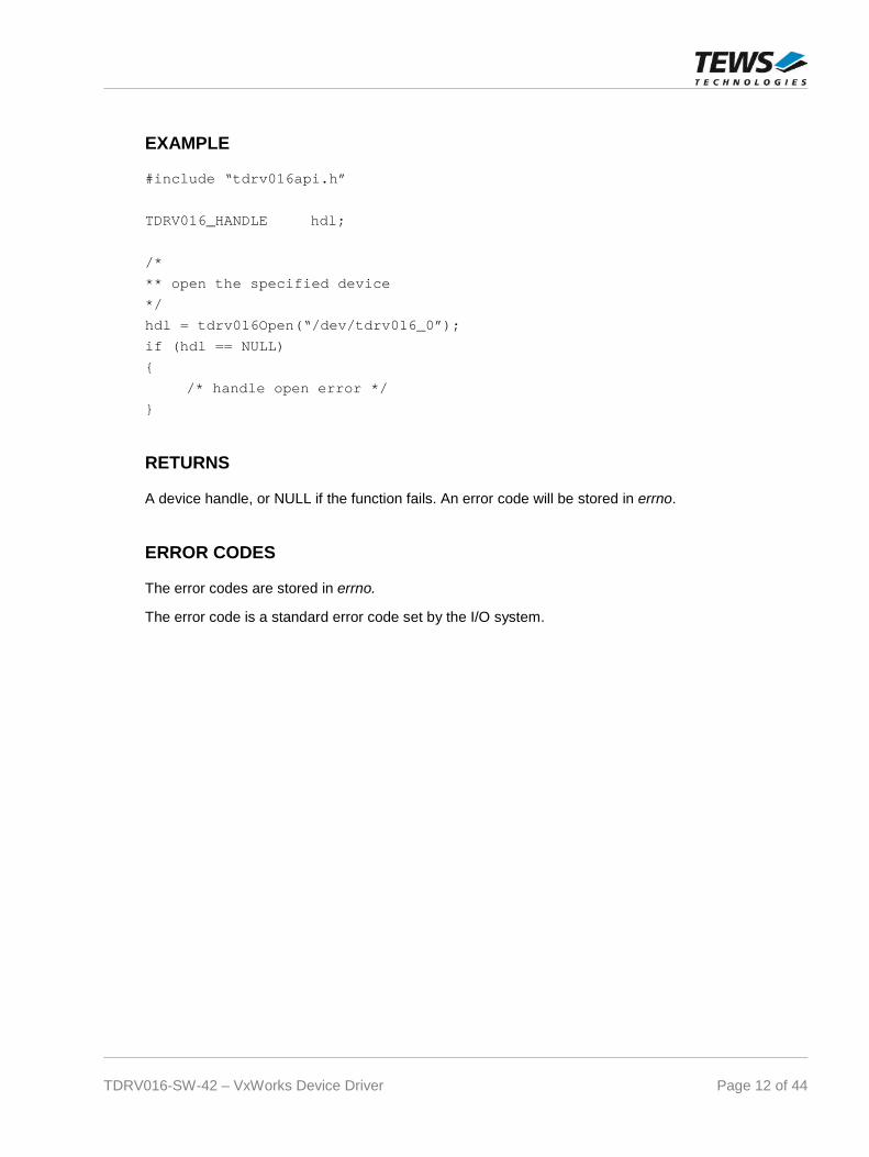
NAME
tdrv016Open – opens a device.
SYNOPSIS
TDRV016_HANDLE tdrv016Open(
char *DeviceName)
DESCRIPTION
Before I/O can be performed to a device, a device handle must be opened by a call to this function. Ifthe legacy TDRV016 driver is used, this function will also install the legacy driver and create deviceswith the first call. The VxBus TDRV016 driver will be installed automatically by the VxBus system.
The tdrv016Open function can be called multiple times (e.g. in different tasks)
PARAMETERS
DeviceName
This parameter points to a null-terminated string that specifies the name of the device. The firstTDRV016 device is named “/dev/tdrv016_0” the second device is named “/dev/tdrv016_1” andso on.
TDRV016-SW-42 – VxWorks Device Driver Page 12 of 44
EXAMPLE
#include “tdrv016api.h”
TDRV016_HANDLE hdl;
/*
** open the specified device
*/
hdl = tdrv016Open(“/dev/tdrv016_0”);
if (hdl == NULL)
{
/* handle open error */
}
RETURNS
A device handle, or NULL if the function fails. An error code will be stored in errno.
ERROR CODES
The error codes are stored in errno.
The error code is a standard error code set by the I/O system.

TDRV016-SW-42 – VxWorks Device Driver Page 13 of 44
3.1.2 tdrv016Close
NAME
tdrv016Close – closes a device.
SYNOPSIS
TDRV016_STATUS tdrv016Close(
TDRV016_HANDLE hdl)
DESCRIPTION
This function closes a previously opened device.
PARAMETERS
hdl
This value specifies the device handle to the hardware module retrieved by a call to thecorresponding open-function.
EXAMPLE
#include “tdrv016api”
TDRV016_HANDLE hdl;
TDRV016_STATUS result;
/*
** close the device
*/
result = tdrv016Close(hdl);
if (result != TDRV016_OK)
{
/* handle close error */
}

TDRV016-SW-42 – VxWorks Device Driver Page 14 of 44
RETURNS
On success, TDRV016_OK is returned. In the case of an error, the appropriate error code is returnedby the function.
ERROR CODES
Error Code Description
TDRV016_ERR_INVALID_HANDLE The specified device handle is invalid

TDRV016-SW-42 – VxWorks Device Driver Page 15 of 44
3.1.3 tdrv016GetModuleInfo
NAME
tdrv016GetModuleInfo – get module information
SYNOPSIS
TDRV016_STATUS tdrv016GetModuleInfo(
TDRV016_HANDLE hdl,int *pModuleType,int *pModuleVariant,int *pPciBusNo,int *pPciDevNo
)
DESCRIPTION
This function retrieves module specific hardware information.
PARAMETERS
hdl
This value specifies the device handle to the hardware module retrieved by a call to thecorresponding open-function.
pModuleType
This argument is a pointer to an int value where the Module Type is returned. Possible valuesare:
Value Description
TDRV016_MODTYPE_TPMC553 TPMC553
TDRV016_MODTYPE_TPMC554 TPMC554
pModuleVariant
This argument is a pointer to an int value where the Module Variant is returned. Possible valuesare:
Value Description
10 -10 (32 D/A channels)
11 -11 (16 D/A channels)
pPciBusNo
This argument is a pointer to an int value where the PCI Bus number of the module is returned.
TDRV016-SW-42 – VxWorks Device Driver Page 16 of 44
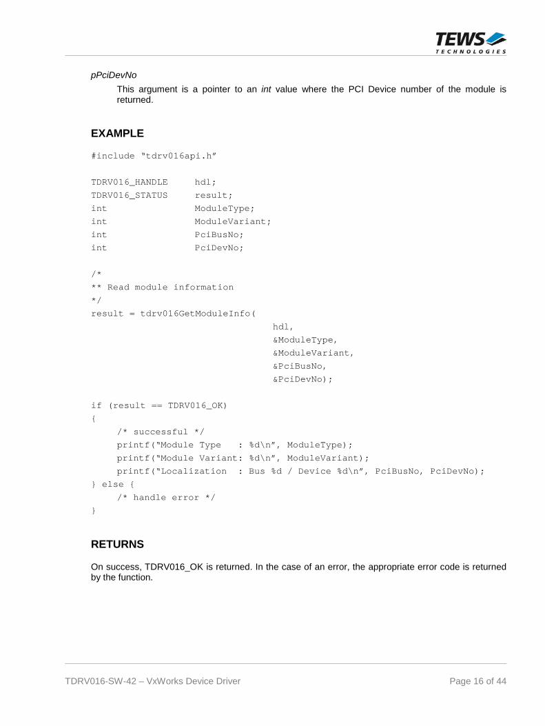
pPciDevNo
This argument is a pointer to an int value where the PCI Device number of the module isreturned.
EXAMPLE
#include “tdrv016api.h”
TDRV016_HANDLE hdl;
TDRV016_STATUS result;
int ModuleType;
int ModuleVariant;
int PciBusNo;
int PciDevNo;
/*
** Read module information
*/
result = tdrv016GetModuleInfo(
hdl,
&ModuleType,
&ModuleVariant,
&PciBusNo,
&PciDevNo);
if (result == TDRV016_OK)
{
/* successful */
printf(“Module Type : %d\n”, ModuleType);
printf(“Module Variant: %d\n”, ModuleVariant);
printf(“Localization : Bus %d / Device %d\n”, PciBusNo, PciDevNo);
} else {
/* handle error */
}
RETURNS
On success, TDRV016_OK is returned. In the case of an error, the appropriate error code is returnedby the function.

TDRV016-SW-42 – VxWorks Device Driver Page 17 of 44
ERROR CODES
Error Code Description
TDRV016_ERR_INVALID_HANDLE The specified device handle is invalid

TDRV016-SW-42 – VxWorks Device Driver Page 18 of 44
3.2 Device Access Functions
3.2.1 tdrv016SetVoltageRange
NAME
tdrv016SetVoltageRange – set voltage range
SYNOPSIS
TDRV016_STATUS tdrv016SetVoltageRange(
TDRV016_HANDLE hdl,int DacChannel,int VoltageRange,int Polarity
)
DESCRIPTION
This function configures the voltage range of a specific D/A channel.
PARAMETERS
hdl
This value specifies the device handle to the hardware module retrieved by a call to thecorresponding open-function.
DacChannel
This argument specifies the DAC channel number. Possible values are 1 up to the availablenumber of channels for the specific module.
VoltageRange
This argument specifies the desired voltage range for the selected DAC channel. Possiblevalues are:
Value Description
TDRV016_VOLTRANGE_5V Vmax = 5V
TDRV016_VOLTRANGE_10V Vmax = 10V
TDRV016_VOLTRANGE_10P8V Vmax = 10.8V
Polarity
This argument specifies the desired polarity for the selected DAC channel. Possible values are:
Value Description
TDRV016_POLARITY_UNIPOL 0V .. +Vmax
TDRV016_POLARITY_BIPOL -Vmax .. +Vmax

TDRV016-SW-42 – VxWorks Device Driver Page 19 of 44
EXAMPLE
#include “tdrv016api.h”
TDRV016_HANDLE hdl;
TDRV016_STATUS result;
/*
** Configure DAC channel 3 to -10V .. +10V
*/
result = tdrv016SetVoltageRange(
hdl,
3,
TDRV016_VOLTRANGE_10V,
TDRV016_POLARITY_BIPOL);
if (result != TDRV016_OK)
{
/* handle error */
}
RETURNS
On success, TDRV016_OK is returned. In the case of an error, the appropriate error code is returnedby the function.
ERROR CODES
Error Code Description
TDRV016_ERR_INVALID_HANDLE The specified device handle is invalid
TDRV016_ERR_INVAL Invalid channel or parameter specified
TDRV016_ERR_IO Error during hardware configuration
TDRV016-SW-42 – VxWorks Device Driver Page 20 of 44
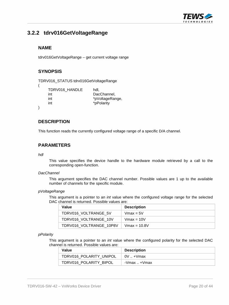
3.2.2 tdrv016GetVoltageRange
NAME
tdrv016GetVoltageRange – get current voltage range
SYNOPSIS
TDRV016_STATUS tdrv016GetVoltageRange(
TDRV016_HANDLE hdl,int DacChannel,int *pVoltageRange,int *pPolarity
)
DESCRIPTION
This function reads the currently configured voltage range of a specific D/A channel.
PARAMETERS
hdl
This value specifies the device handle to the hardware module retrieved by a call to thecorresponding open-function.
DacChannel
This argument specifies the DAC channel number. Possible values are 1 up to the availablenumber of channels for the specific module.
pVoltageRange
This argument is a pointer to an int value where the configured voltage range for the selectedDAC channel is returned. Possible values are:
Value Description
TDRV016_VOLTRANGE_5V Vmax = 5V
TDRV016_VOLTRANGE_10V Vmax = 10V
TDRV016_VOLTRANGE_10P8V Vmax = 10.8V
pPolarity
This argument is a pointer to an int value where the configured polarity for the selected DACchannel is returned. Possible values are:
Value Description
TDRV016_POLARITY_UNIPOL 0V .. +Vmax
TDRV016_POLARITY_BIPOL -Vmax .. +Vmax

TDRV016-SW-42 – VxWorks Device Driver Page 21 of 44
EXAMPLE
#include “tdrv016api.h”
TDRV016_HANDLE hdl;
TDRV016_STATUS result;
int VoltageRange, Polarity
/*
** Read current voltage range configuration of DAC channel 3
*/
result = tdrv016GetVoltageRange(
hdl,
3,
&VoltageRange,
&Polarity);
if (result != TDRV016_OK)
{
/* handle error */
}
RETURNS
On success, TDRV016_OK is returned. In the case of an error, the appropriate error code is returnedby the function.
ERROR CODES
Error Code Description
TDRV016_ERR_INVALID_HANDLE The specified device handle is invalid
TDRV016_ERR_INVAL Invalid channel specified

TDRV016-SW-42 – VxWorks Device Driver Page 22 of 44
3.2.3 tdrv016QDacConfig
NAME
tdrv016QDacConfig – configure Q-DAC mode
SYNOPSIS
TDRV016_STATUS tdrv016QDacConfig(
TDRV016_HANDLE hdl,int QDacNumber,int QDacMode,int GlobalLoadMode
)
DESCRIPTION
This function configures the operation mode of a specific Q-DAC, which serves 4 single D/A channels.
PARAMETERS
hdl
This value specifies the device handle to the hardware module retrieved by a call to thecorresponding open-function.
QDacNumber
This argument specifies the Q-DAC number. Possible values are 1 up to the available numberof Q-DACs for the specific module. Q-DAC 1 serves D/A channels 1 to 4, Q-DAC 2 serves D/Achannels 5 to 8 and so on.
QDacMode
This argument specifies the desired operation mode for the selected Q-DAC. Possible valuesare:
Value Description
TDRV016_QDACMODE_INSTANT Instant Mode. DAC values are writtenimmediately.
TDRV016_QDACMODE_MANUAL Manual mode. DAC values are written aftermanual load operation.
TDRV016_QDACMODE_TIMER Timer mode. DAC values are written insequencer mode.
GlobalLoadMode
This argument specifies if the Q-DAC should synchronize to other Q-DACs. If TRUE, allselected Q-DACs are updated simultaneously. This parameter is only relevant for Manualmode.

TDRV016-SW-42 – VxWorks Device Driver Page 23 of 44
EXAMPLE
#include “tdrv016api.h”
TDRV016_HANDLE hdl;
TDRV016_STATUS result;
/*
** Configure Q-DAC 1 (D/A channel 1 to 4)
** - use Manual Mode without global synchronization
*/
result = tdrv016QDacConfig(
hdl,
1,
TDRV016_QDACMODE_MANUAL,
FALSE);
if (result != TDRV016_OK)
{
/* handle error */
}
RETURNS
On success, TDRV016_OK is returned. In the case of an error, the appropriate error code is returnedby the function.
ERROR CODES
Error Code Description
TDRV016_ERR_INVALID_HANDLE The specified device handle is invalid
TDRV016_ERR_INVAL Invalid channel or parameter specified
TDRV016_ERR_IO Error during hardware configuration

TDRV016-SW-42 – VxWorks Device Driver Page 24 of 44
3.2.4 tdrv016DacWrite
NAME
tdrv016DacWrite – Write one DAC value to a specific DAC channel
SYNOPSIS
TDRV016_STATUS tdrv016DacWrite(
TDRV016_HANDLE hdl,int DacChannel,int DacValue,int Flags
)
DESCRIPTION
This function writes one DAC value to a specific DAC channel. This function is supported for channelsconfigured to Instant or Manual Mode.
PARAMETERS
hdl
This value specifies the device handle to the hardware module retrieved by a call to thecorresponding open-function.
DacChannel
This argument specifies the DAC channel which shall be updated. Possible values are 1 up tothe number of available DAC channels of the specific module.
DacValue
This argument specifies the new DAC value for the specified channel.
Flags
This argument specifies additional options for this DAC update. Possible OR’ed flags are:
Value Description
TDRV016_CORR Use data correction for this conversion.
TDRV016_LOAD Perform Load Operation for correspondingQ-DAC (only if Q-DAC is in Manual Mode).
TDRV016-SW-42 – VxWorks Device Driver Page 25 of 44
EXAMPLE
#include “tdrv016api.h”
TDRV016_HANDLE hdl;
TDRV016_STATUS result;
/*
** Write new DAC value to channel 1, use data correction.
*/
result = tdrv016DacWrite(
hdl,
1,
0x1000,
TDRV016_CORR);
if (result != TDRV016_OK)
{
/* handle error */
}
RETURNS
On success, TDRV016_OK is returned. In the case of an error, the appropriate error code is returnedby the function.
ERROR CODES
Error Code Description
TDRV016_ERR_INVALID_HANDLE The specified device handle is invalid
TDRV016_ERR_INVAL Invalid channel specified
TDRV016_ERR_ACCESS Specified channel not configured to I- or M-Mode

TDRV016-SW-42 – VxWorks Device Driver Page 26 of 44
3.2.5 tdrv016DacWriteMulti
NAME
tdrv016DacWriteMulti – Write DAC values to multiple DAC channels
SYNOPSIS
TDRV016_STATUS tdrv016DacWriteMulti(
TDRV016_HANDLE hdl,unsigned int DacChannelMask,unsigned int CorrectionMask,int PerformLoad,unsigned short DacData[32]
)
DESCRIPTION
This function writes different DAC value to specified DAC channels. This function is supported forchannels configured to Instant or Manual Mode.
PARAMETERS
hdl
This value specifies the device handle to the hardware module retrieved by a call to thecorresponding open-function.
DacChannelMask
This argument specifies DAC channels which shall be updated. A set (1) bit specifies that thecorresponding channel shall be updated. Bit 0 corresponds to the first DAC channel, bit 1corresponds to the second DAC channel and so on.
CorrectionMask
This argument specifies if data correction shall be used for specific DAC channels. A set (1) bitenables data correction for the corresponding channel. Bit 0 corresponds to the first DACchannel, bit 1 corresponds to the second DAC channel and so on.
PerformLoad
This argument specifies if the corresponding Q-DACs shall be updated. If TRUE, all affected Q-DACs are updated using the Load Operation. If this parameter is FALSE, all Q-DACs configuredto Manual Mode will not be updated.
DacData
This argument specifies the new DAC data. Array index 0 corresponds to the first DAC channel,array index 1 corresponds to the second DAC channel and so on. Only channels marked forupdate using parameter DacChannelMask will be modified.

TDRV016-SW-42 – VxWorks Device Driver Page 27 of 44
EXAMPLE
#include “tdrv016api.h”
TDRV016_HANDLE hdl;
TDRV016_STATUS result;
unsigned short DacData[32];
/*
** Write new DAC values to channel 1, 2 and 32.
** Use data correction only for channel 1.
** Update all channels which are in M-Mode.
*/
DacData[0] = 0x1000;
DacData[1] = 0x2000;
DacData[31] = 0x0000;
result = tdrv016DacWriteMulti(
hdl,
((1 << 31) | (1 << 1) | (1 << 0)),
(1 << 0),
TRUE,
DacData);
if (result != TDRV016_OK)
{
/* handle error */
}
RETURNS
On success, TDRV016_OK is returned. In the case of an error, the appropriate error code is returnedby the function.
ERROR CODES
Error Code Description
TDRV016_ERR_INVALID_HANDLE The specified device handle is invalid
TDRV016_ERR_ACCESS At least one of the specified channels is not in I- or M-Mode

TDRV016-SW-42 – VxWorks Device Driver Page 28 of 44
3.2.6 tdrv016QDacLoad
NAME
tdrv016QDacLoad – Perform Load Operation for specified Q-DACs
SYNOPSIS
TDRV016_STATUS tdrv016QDacLoad(
TDRV016_HANDLE hdl,unsigned int QDacMask
)
DESCRIPTION
This function performs the Load Operation for specified Q-DACs, to achieve simultaneous update ofmultiple DAC channels. This function is supported for Q-DACs configured to Manual Mode.
PARAMETERS
hdl
This value specifies the device handle to the hardware module retrieved by a call to thecorresponding open-function.
QDacMask
This argument specifies the Q-DACs which shall be loaded. A set (1) bit specifies that thecorresponding Q-DAC shall be loaded. Bit 0 corresponds to the first Q-DAC (DAC channels 1 to4), bit 1 corresponds to the second Q-DAC (DAC channels 5 to 8) and so on.

TDRV016-SW-42 – VxWorks Device Driver Page 29 of 44
EXAMPLE
#include “tdrv016api.h”
TDRV016_HANDLE hdl;
TDRV016_STATUS result;
/*
** Load Q-DACs 1 and 8 simultaneously.
*/
result = tdrv016QDacLoad(
hdl,
((1 << 7) | (1 << 0)));
if (result != TDRV016_OK)
{
/* handle error */
}
RETURNS
On success, TDRV016_OK is returned. In the case of an error, the appropriate error code is returnedby the function.
ERROR CODES
Error Code Description
TDRV016_ERR_INVALID_HANDLE The specified device handle is invalid
TDRV016_ERR_ACCESS At least one of the Q-DACs is not in M-Mode.
TDRV016-SW-42 – VxWorks Device Driver Page 30 of 44
3.3 Sequencer Functions
3.3.1 tdrv016SequencerConfig
NAME
tdrv016SequencerConfig – configure sequencer cycle time
SYNOPSIS
TDRV016_STATUS tdrv016SequencerConfig(
TDRV016_HANDLE hdl,int QDacNumber,unsigned int CycleTime
)
DESCRIPTION
This function configures the sequencer cycle time of a specific Q-DAC, which serves 4 single D/Achannels. The configured sequencer cycle time is used in both Timer and FIFO mode.
PARAMETERS
hdl
This value specifies the device handle to the hardware module retrieved by a call to thecorresponding open-function.
QDacNumber
This argument specifies the Q-DAC number. Possible values are 1 up to the available numberof Q-DACs for the specific module. Q-DAC 1 serves D/A channels 1 to 4, Q-DAC 2 serves D/Achannels 5 to 8 and so on.
CycleTime
This argument specifies the sequencer cycle time. The sequencer timer is configurable in stepsof 10µs. Possible values are 0 to the maximum value specified in the corresponding modulehardware user manual. The calculation formula for the resulting cycle time is:ResultingCycleTime = (CycleTime + 1) x 10µs

TDRV016-SW-42 – VxWorks Device Driver Page 31 of 44
EXAMPLE
#include “tdrv016api.h”
TDRV016_HANDLE hdl;
TDRV016_STATUS result;
/*
** Configure Sequencer Timer of Q-DAC 1 (D/A channel 1 to 4)
** Using 1ms cycle time results in a register value of 99.
*/
result = tdrv016SequencerConfig(
hdl,
1,
99);
if (result != TDRV016_OK)
{
/* handle error */
}
RETURNS
On success, TDRV016_OK is returned. In the case of an error, the appropriate error code is returnedby the function.
ERROR CODES
Error Code Description
TDRV016_ERR_INVALID_HANDLE The specified device handle is invalid
TDRV016_ERR_INVAL Invalid Q-DAC specified.

TDRV016-SW-42 – VxWorks Device Driver Page 32 of 44
3.3.2 tdrv016SequencerStart
NAME
tdrv016SequencerStart – start sequencer timer
SYNOPSIS
TDRV016_STATUS tdrv016SequencerStart(
TDRV016_HANDLE hdl,unsigned int SequencerMask
)
DESCRIPTION
This function starts the sequencer timer of specified Q-DACs. This function starts the sequenceroperation of both Timer and FIFO mode.
PARAMETERS
hdl
This value specifies the device handle to the hardware module retrieved by a call to thecorresponding open-function.
SequencerMask
This argument specifies the Q-DACs which shall be started in sequencer mode. A set (1) bitspecifies that the corresponding Q-DAC shall be started. Bit 0 corresponds to the first Q-DAC(DAC channels 1 to 4), bit 1 corresponds to the second Q-DAC (DAC channels 5 to 8) and soon.
TDRV016-SW-42 – VxWorks Device Driver Page 33 of 44
EXAMPLE
#include “tdrv016api.h”
TDRV016_HANDLE hdl;
TDRV016_STATUS result;
/*
** Start Sequencer Timer of Q-DAC 1 and 2
*/
result = tdrv016SequencerStart(hdl, (1 << 1) | (1 << 0));
if (result != TDRV016_OK)
{
/* handle error */
}
RETURNS
On success, TDRV016_OK is returned. In the case of an error, the appropriate error code is returnedby the function.
ERROR CODES
Error Code Description
TDRV016_ERR_INVALID_HANDLE The specified device handle is invalid
TDRV016_ERR_ACCESS At least one of the Q-DACs is not in Timer or FIFOmode.

TDRV016-SW-42 – VxWorks Device Driver Page 34 of 44
3.3.3 tdrv016SequencerStop
NAME
tdrv016SequencerStop – stop sequencer timer
SYNOPSIS
TDRV016_STATUS tdrv016SequencerStop(
TDRV016_HANDLE hdl,unsigned int SequencerMask
)
DESCRIPTION
This function stops the sequencer timer of specified Q-DACs. This function stops the sequenceroperation of both Timer and FIFO mode.
PARAMETERS
hdl
This value specifies the device handle to the hardware module retrieved by a call to thecorresponding open-function.
SequencerMask
This argument specifies the Q-DACs which shall be stopped. A set (1) bit specifies that thecorresponding Q-DAC shall be stopped. Bit 0 corresponds to the first Q-DAC (DAC channels 1to 4), bit 1 corresponds to the second Q-DAC (DAC channels 5 to 8) and so on.

TDRV016-SW-42 – VxWorks Device Driver Page 35 of 44
EXAMPLE
#include “tdrv016api.h”
TDRV016_HANDLE hdl;
TDRV016_STATUS result;
/*
** Stop Sequencer Timer of Q-DAC 2
*/
result = tdrv016SequencerStop(hdl, (1 << 1));
if (result != TDRV016_OK)
{
/* handle error */
}
RETURNS
On success, TDRV016_OK is returned. In the case of an error, the appropriate error code is returnedby the function.
ERROR CODES
Error Code Description
TDRV016_ERR_INVALID_HANDLE The specified device handle is invalid

TDRV016-SW-42 – VxWorks Device Driver Page 36 of 44
3.3.4 tdrv016SequencerWrite
NAME
tdrv016SequencerWrite – Write DAC data in Timer mode
SYNOPSIS
TDRV016_STATUS tdrv016SequencerWrite(
TDRV016_HANDLE hdl,int QDacNumber,unsigned int UseCorrection,int DacValue[4],int timeout
)
DESCRIPTION
This function writes new DAC data to a specific Q-DAC, which serves 4 single D/A channels. All fourchannels of the Q-DAC are affected. This function is only supported in Timer Mode. This functionmight block until the next sequencer interrupt allows transferrin the DAC data, or the timeout expires.
PARAMETERS
hdl
This value specifies the device handle to the hardware module retrieved by a call to thecorresponding open-function.
QDacNumber
This argument specifies the Q-DAC number. Possible values are 1 up to the available numberof Q-DACs for the specific module. Q-DAC 1 serves D/A channels 1 to 4, Q-DAC 2 serves D/Achannels 5 to 8 and so on.
UseCorrection
This argument specifies if data correction shall be used for specific DAC channels. A set (1) bitenables data correction for the corresponding channel. Bit 0 corresponds to the first DACchannel of the Q-DAC, bit 1 corresponds to the second DAC channel of the Q-DAC and so on.
DacValue
This argument specifies the new DAC data. Array index 0 corresponds to the first DAC channelof the Q-DAC, array index 1 corresponds to the second DAC channel of the Q-DAC and so on.

TDRV016-SW-42 – VxWorks Device Driver Page 37 of 44
timeout
This parameter specifies the time the function will block until the data is transferred into theDAC channels, which is done using interrupts. The interrupts are raised based upon theconfigured sequencer cycle time, so this timeout value must be chosen according to theconfigured cycle time. This timeout value is specified in milliseconds. The resulting timedepends on the system tick granularity. To wait indefinitely, specify -1.
EXAMPLE
#include “tdrv016api.h”
TDRV016_HANDLE hdl;
TDRV016_STATUS result;
int DacData[4];
/*
** Write new data to Q-DAC 2 without data correction.
** Use 500ms for timeout.
*/
result = tdrv016SequencerWrite(
hdl,
2,
0,
DacData,
500);
if (result != TDRV016_OK)
{
/* handle error */
}
RETURNS
On success, TDRV016_OK is returned. In the case of an error, the appropriate error code is returnedby the function.
ERROR CODES
Error Code Description
TDRV016_ERR_INVALID_HANDLE The specified device handle is invalid
TDRV016_ERR_INVAL Invalid Q-DAC specified.
TDRV016_ERR_ACCESS Specified Q-DAC is not in Timer-Mode.
TDRV016_ERR_TIMEOUT Timeout while waiting for sequencer interrupt.

TDRV016-SW-42 – VxWorks Device Driver Page 38 of 44
3.4 FIFO Functions
3.4.1 tdrv016FifoConfig
NAME
tdrv016FifoConfig – configure FIFO mode (TPMC554 only)
SYNOPSIS
TDRV016_STATUS tdrv016FifoConfig(
TDRV016_HANDLE hdl,unsigned int DacChannelMask,unsigned int ContinuousModeMask,int Size[32],int Limit[32]
)
DESCRIPTION
This function configures the FIFO mode of specified DAC channels. All four channels of one affectedQ-DAC are used in FIFO mode. All channels which were previously configured to FIFO mode and arenot again configured with this function are configured to Instant mode without changing the DACvalue.
PARAMETERS
hdl
This value specifies the device handle to the hardware module retrieved by a call to thecorresponding open-function.
DacChannelMask
This argument specifies the DAC channels which shall be used in FIFO mode. All four DACchannels of one affected Q-DAC must be configured for FIFO mode. A set (1) bit specifies thatthe corresponding channel shall be configured. Bit 0 corresponds to the first DAC channel, bit 1corresponds to the second DAC channel and so on.
ContinuousModeMask
This argument specifies if the corresponding DAC channel FIFO shall be used in continuousmode. A set (1) configures the corresponding channel to repeat its FIFO data. An unset (0) bitconfigures the channel to stop the data output if the FIFO runs empty. Bit 0 corresponds to thefirst DAC channel, bit 1 corresponds to the second DAC channel and so on.
Size
This argument specifies the size of the FIFO in number of values. Array index 0 corresponds tothe first DAC channel, array index 1 corresponds to the second DAC channel and so on.
TDRV016-SW-42 – VxWorks Device Driver Page 39 of 44
Limit
This argument specifies the FIFO trigger limit where an interrupt is raised. The limit is specifiedas 2
Limit. Array index 0 corresponds to the first DAC channel, array index 1 corresponds to the
second DAC channel and so on.
EXAMPLE
#include “tdrv016api.h”
TDRV016_HANDLE hdl;
TDRV016_STATUS result;
int Size[32];
int Limit[32];
/*
** Configure FIFO mode for channel 1 to 8
** - Use DAC 1 and 4 in Continuous Mode
*/
Size[0] = 100;
Limit[0] = 5; /* Limit at 32 values */
...
result = tdrv016FifoConfig(
hdl,
0x000000ff,
(1 << 3) | (1 << 0),
Size,
Limit);
if (result != TDRV016_OK)
{
/* handle error */
}
RETURNS
On success, TDRV016_OK is returned. In the case of an error, the appropriate error code is returnedby the function.

TDRV016-SW-42 – VxWorks Device Driver Page 40 of 44
ERROR CODES
Error Code Description
TDRV016_ERR_INVALID_HANDLE The specified device handle is invalid
TDRV016_ERR_INVAL Not all DAC channels of a Q-DAC specified, invalidSize or Limit.
TDRV016_ERR_ACCESS Module does not support FIFO mode.

TDRV016-SW-42 – VxWorks Device Driver Page 41 of 44
3.4.2 tdrv016FifoWrite
NAME
tdrv016FifoWrite – Write DAC data in FIFO mode (TPMC554 only)
SYNOPSIS
TDRV016_STATUS tdrv016FifoWrite(
TDRV016_HANDLE hdl,int DacChannel,unsigned int Flags,int NumValues,unsigned short *pDacData,int timeout
)
DESCRIPTION
This function writes new DAC data of a specific DAC channel into the FIFO. This function is onlysupported in FIFO Mode. The function blocks until all data is written into the FIFO, or the timeoutexpires.
PARAMETERS
hdl
This value specifies the device handle to the hardware module retrieved by a call to thecorresponding open-function.
DacChannel
This argument specifies the DAC channel number. Possible values are 1 up to the availablenumber of DACs for the specific module.
Flags
This argument specifies additional options for this DAC update. Possible value:
Value Description
TDRV016_CORR Use data correction for all values.
NumValues
This argument specifies the number of DAC data values which shall be written into the FIFO.
pDacData
This parameter points to the DAC data section where the specified number of 16bit values isstored.

TDRV016-SW-42 – VxWorks Device Driver Page 42 of 44
timeout
This parameter specifies the time the function will block until the data is transferred into theFIFO, which might be done using interrupts. The interrupts are raised based upon theconfigured sequencer cycle time, so this timeout value must be chosen according to theconfigured cycle time. This timeout value is specified in milliseconds. The resulting timedepends on the system tick granularity. To wait indefinitely, specify -1.
The timeout value specifies the time to wait for the next interrupt. Multiple interrupts might berequired to transfer the complete amount of specified data into the FIFO.
EXAMPLE
#include “tdrv016api.h”
TDRV016_HANDLE hdl;
TDRV016_STATUS result;
unsigned short DacData[100];
/*
** Write 100 DAC data values to FIFO channel 2 with data correction.
** Use 500ms for timeout.
*/
DacData[0] = 0x1234;
DacData[1] = 0x5678;
DacData[2] = 0x9ABC;
...
result = tdrv016FifoWrite(
hdl,
2,
TDRV016_CORR,
100,
DacData,
500);
if (result != TDRV016_OK)
{
/* handle error */
}
RETURNS
On success, TDRV016_OK is returned. In the case of an error, the appropriate error code is returnedby the function.

TDRV016-SW-42 – VxWorks Device Driver Page 43 of 44
ERROR CODES
Error Code Description
TDRV016_ERR_INVALID_HANDLE The specified device handle is invalid
TDRV016_ERR_INVAL Invalid Channel specified.
TDRV016_ERR_ACCESS Module does not support FIFO mode, or channel isnot in FIFO mode.
TDRV016_ERR_BUSY This DAC channel is already busy transferring datainto the FIFO.
TDRV016_ERR_TIMEOUT Timeout while waiting for FIFO interrupt.
TDRV016-SW-42 – VxWorks Device Driver Page 44 of 44
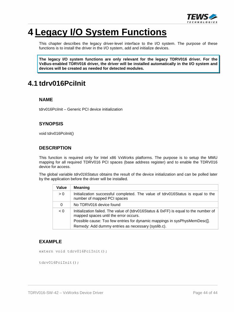
4 Legacy I/O System FunctionsThis chapter describes the legacy driver-level interface to the I/O system. The purpose of thesefunctions is to install the driver in the I/O system, add and initialize devices.
The legacy I/O system functions are only relevant for the legacy TDRV016 driver. For theVxBus-enabled TDRV016 driver, the driver will be installed automatically in the I/O system anddevices will be created as needed for detected modules.
4.1 tdrv016PciInit
NAME
tdrv016PciInit – Generic PCI device initialization
SYNOPSIS
void tdrv016PciInit()
DESCRIPTION
This function is required only for Intel x86 VxWorks platforms. The purpose is to setup the MMUmapping for all required TDRV016 PCI spaces (base address register) and to enable the TDRV016device for access.
The global variable tdrv016Status obtains the result of the device initialization and can be polled laterby the application before the driver will be installed.
Value Meaning
> 0 Initialization successful completed. The value of tdrv016Status is equal to thenumber of mapped PCI spaces
0 No TDRV016 device found
< 0 Initialization failed. The value of (tdrv016Status & 0xFF) is equal to the number ofmapped spaces until the error occurs.
Possible cause: Too few entries for dynamic mappings in sysPhysMemDesc[].
Remedy: Add dummy entries as necessary (syslib.c).
EXAMPLE
extern void tdrv016PciInit();
tdrv016PciInit();