Embed Size (px)
Citation preview

TDR880i Instruction Manual
PS11021AENBB0101.02/EN

DECLARATION OF CONFORMITY We, EADS Secure Networks, declare under our sole responsibility that the product EADS TDR880i is in conformity with the provisions of the
following Council Directives:1999/5/EC (R&TTE) & 2002/95/EC (ROHS). Copies of the Declaration of Conformity can be found at http://www.eads.com/tdr880i.
Copyright © 2008 EADS Secure Networks. All rights reserved.
The document is confidential and contains legally privileged information. The document may only be used for the purpose for which it is submitted. Reproduction, transfer, distribution or storage of part or all of the contents in this document in any form without the prior written permission of EADS Secure Networks is prohibited.
EADS logo is a registered trademark of EADS N.V. Other product and company names, trademarks or other identifiers mentioned herein may be trademarks or tradenames of their respective owners.
Includes RSA BSAFE cryptographic or security protocol software from RSA Security.
EADS Secure Networks operates a policy of continuous development. EADS Secure Networks reserves the right to make changes and improvements to any of the products described in this document without prior notice.
Under no circumstances shall EADS Secure Networks be responsible for any loss of data or income or any special, incidental, consequential or indirect damages howsoever caused.
The contents of this document are provided "as is". Except as required by applicable law, no warranties of any kind, either express or implied, including, but not limited to, the implied warranties of merchantability and fitness for a particular purpose, are made in relation to the accuracy, reliability or contents of this document. EADS Secure Networks reserves the right to revise this document or withdraw it at any time without prior notice.
The crossed-out wheeled bin means that within the European Union the product must be taken to separate collection at the product end-of-life. This applies to your device but also to any enhancements marked with this symbol. Do not dispose of these products as unsorted municipal waste. Please deliver this product after operational life to your distributor or sales representative for recycling.
This document is the property of EADS Secure Networks and should not be copied or circulated without permission.
2

Contents
1. INTRODUCTION . . . . . . . . . . . . . . . . . . . . . . . . . . . . . . . . . . . . . . . . . . . . . . . . . . . . . . . . . . . . . . . . . . . . . 5General . . . . . . . . . . . . . . . . . . . . . . . . . . . . . . . . . . . . . . . . . . . . . . . . . . . . . . . . . . . . . . . . . . . . . . . . . . . . . . . . . . . . . . . . . . . . . . . . . 5
Company policy. . . . . . . . . . . . . . . . . . . . . . . . . . . . . . . . . . . . . . . . . . . . . . . . . . . . . . . . . . . . . . . . . . . . . . . . . . . . . . . . . . . . . . . . 5Typographic conventions. . . . . . . . . . . . . . . . . . . . . . . . . . . . . . . . . . . . . . . . . . . . . . . . . . . . . . . . . . . . . . . . . . . . . . . . . . . . . . . . . . . . 5
2. IMPORTANT SAFETY INFORMATION . . . . . . . . . . . . . . . . . . . . . . . . . . . . . . . . . . . . . . . . . . . . . . . . . . . 6Operating environment . . . . . . . . . . . . . . . . . . . . . . . . . . . . . . . . . . . . . . . . . . . . . . . . . . . . . . . . . . . . . . . . . . . . . . . . . . . . . . . . . . . . . 6Medical devices . . . . . . . . . . . . . . . . . . . . . . . . . . . . . . . . . . . . . . . . . . . . . . . . . . . . . . . . . . . . . . . . . . . . . . . . . . . . . . . . . . . . . . . . . . . 6
Pacemakers . . . . . . . . . . . . . . . . . . . . . . . . . . . . . . . . . . . . . . . . . . . . . . . . . . . . . . . . . . . . . . . . . . . . . . . . . . . . . . . . . . . . . . . . . . 6Hearing aids . . . . . . . . . . . . . . . . . . . . . . . . . . . . . . . . . . . . . . . . . . . . . . . . . . . . . . . . . . . . . . . . . . . . . . . . . . . . . . . . . . . . . . . . . . 6
Vehicles . . . . . . . . . . . . . . . . . . . . . . . . . . . . . . . . . . . . . . . . . . . . . . . . . . . . . . . . . . . . . . . . . . . . . . . . . . . . . . . . . . . . . . . . . . . . . . . . . 6Aircrafts . . . . . . . . . . . . . . . . . . . . . . . . . . . . . . . . . . . . . . . . . . . . . . . . . . . . . . . . . . . . . . . . . . . . . . . . . . . . . . . . . . . . . . . . . . . . . . . . . 6Potentially explosive environments . . . . . . . . . . . . . . . . . . . . . . . . . . . . . . . . . . . . . . . . . . . . . . . . . . . . . . . . . . . . . . . . . . . . . . . . . . . . 7Care and maintenance . . . . . . . . . . . . . . . . . . . . . . . . . . . . . . . . . . . . . . . . . . . . . . . . . . . . . . . . . . . . . . . . . . . . . . . . . . . . . . . . . . . . . 7
3. DEVICE OVERVIEW . . . . . . . . . . . . . . . . . . . . . . . . . . . . . . . . . . . . . . . . . . . . . . . . . . . . . . . . . . . . . . . . . . 8Accessories . . . . . . . . . . . . . . . . . . . . . . . . . . . . . . . . . . . . . . . . . . . . . . . . . . . . . . . . . . . . . . . . . . . . . . . . . . . . . . . . . . . . . . . . . . . . . . 8
External AC Power Supply ACR-2E . . . . . . . . . . . . . . . . . . . . . . . . . . . . . . . . . . . . . . . . . . . . . . . . . . . . . . . . . . . . . . . . . . . . . . . . 9DC Power Cable CA-113 . . . . . . . . . . . . . . . . . . . . . . . . . . . . . . . . . . . . . . . . . . . . . . . . . . . . . . . . . . . . . . . . . . . . . . . . . . . . . . . . 9Data Cable CA-109 . . . . . . . . . . . . . . . . . . . . . . . . . . . . . . . . . . . . . . . . . . . . . . . . . . . . . . . . . . . . . . . . . . . . . . . . . . . . . . . . . . . . . 9Flashing and Parametering Adapter CA-115 . . . . . . . . . . . . . . . . . . . . . . . . . . . . . . . . . . . . . . . . . . . . . . . . . . . . . . . . . . . . . . . . . 9Fixed TETRA Antenna Kit AN-7 . . . . . . . . . . . . . . . . . . . . . . . . . . . . . . . . . . . . . . . . . . . . . . . . . . . . . . . . . . . . . . . . . . . . . . . . . . . 9Magnet Mount TETRA Antenna Kit AN-9 . . . . . . . . . . . . . . . . . . . . . . . . . . . . . . . . . . . . . . . . . . . . . . . . . . . . . . . . . . . . . . . . . . . . 9Magnet Mount GPS Antenna AN-5 . . . . . . . . . . . . . . . . . . . . . . . . . . . . . . . . . . . . . . . . . . . . . . . . . . . . . . . . . . . . . . . . . . . . . . . . . 9Combined TETRA/GPS Antenna Kit AN-6 . . . . . . . . . . . . . . . . . . . . . . . . . . . . . . . . . . . . . . . . . . . . . . . . . . . . . . . . . . . . . . . . . . . 9
PC Software . . . . . . . . . . . . . . . . . . . . . . . . . . . . . . . . . . . . . . . . . . . . . . . . . . . . . . . . . . . . . . . . . . . . . . . . . . . . . . . . . . . . . . . . . . . . 10CE marking in the TDR880i . . . . . . . . . . . . . . . . . . . . . . . . . . . . . . . . . . . . . . . . . . . . . . . . . . . . . . . . . . . . . . . . . . . . . . . . . . . . . . . . . 10
4. INSTALLATION. . . . . . . . . . . . . . . . . . . . . . . . . . . . . . . . . . . . . . . . . . . . . . . . . . . . . . . . . . . . . . . . . . . . . 11Safety warnings and cautions . . . . . . . . . . . . . . . . . . . . . . . . . . . . . . . . . . . . . . . . . . . . . . . . . . . . . . . . . . . . . . . . . . . . . . . . . . . . . . . 11Environmental conditions . . . . . . . . . . . . . . . . . . . . . . . . . . . . . . . . . . . . . . . . . . . . . . . . . . . . . . . . . . . . . . . . . . . . . . . . . . . . . . . . . . 12Tools and installation materials . . . . . . . . . . . . . . . . . . . . . . . . . . . . . . . . . . . . . . . . . . . . . . . . . . . . . . . . . . . . . . . . . . . . . . . . . . . . . . 12
Cable types, making of cables . . . . . . . . . . . . . . . . . . . . . . . . . . . . . . . . . . . . . . . . . . . . . . . . . . . . . . . . . . . . . . . . . . . . . . . . . . . 12Installation procedure . . . . . . . . . . . . . . . . . . . . . . . . . . . . . . . . . . . . . . . . . . . . . . . . . . . . . . . . . . . . . . . . . . . . . . . . . . . . . . . . . . . . . 13
Installing the TDR880i . . . . . . . . . . . . . . . . . . . . . . . . . . . . . . . . . . . . . . . . . . . . . . . . . . . . . . . . . . . . . . . . . . . . . . . . . . . . . . . . . . 14Cabling . . . . . . . . . . . . . . . . . . . . . . . . . . . . . . . . . . . . . . . . . . . . . . . . . . . . . . . . . . . . . . . . . . . . . . . . . . . . . . . . . . . . . . . . . . . . . . . . 14
Connecting the power supply . . . . . . . . . . . . . . . . . . . . . . . . . . . . . . . . . . . . . . . . . . . . . . . . . . . . . . . . . . . . . . . . . . . . . . . . . . . . 14Special considerations for vehicles, vessels etc. . . . . . . . . . . . . . . . . . . . . . . . . . . . . . . . . . . . . . . . . . . . . . . . . . . . . . . . . . . . . . 14Lightning protection. . . . . . . . . . . . . . . . . . . . . . . . . . . . . . . . . . . . . . . . . . . . . . . . . . . . . . . . . . . . . . . . . . . . . . . . . . . . . . . . . . . . 14
Grounding . . . . . . . . . . . . . . . . . . . . . . . . . . . . . . . . . . . . . . . . . . . . . . . . . . . . . . . . . . . . . . . . . . . . . . . . . . . . . . . . . . . . . . . . . . . . . . 15Starting up . . . . . . . . . . . . . . . . . . . . . . . . . . . . . . . . . . . . . . . . . . . . . . . . . . . . . . . . . . . . . . . . . . . . . . . . . . . . . . . . . . . . . . . . . . . . . . 15
Starting up after flash / parametrization . . . . . . . . . . . . . . . . . . . . . . . . . . . . . . . . . . . . . . . . . . . . . . . . . . . . . . . . . . . . . . . . . . . . 15Verifying the AT functionality. . . . . . . . . . . . . . . . . . . . . . . . . . . . . . . . . . . . . . . . . . . . . . . . . . . . . . . . . . . . . . . . . . . . . . . . . . . . . 15Verifying the parametrization functionality . . . . . . . . . . . . . . . . . . . . . . . . . . . . . . . . . . . . . . . . . . . . . . . . . . . . . . . . . . . . . . . . . . 15
5. FEATURE GUIDE . . . . . . . . . . . . . . . . . . . . . . . . . . . . . . . . . . . . . . . . . . . . . . . . . . . . . . . . . . . . . . . . . . . 16Feature overview . . . . . . . . . . . . . . . . . . . . . . . . . . . . . . . . . . . . . . . . . . . . . . . . . . . . . . . . . . . . . . . . . . . . . . . . . . . . . . . . . . . . . . . . . 16Tracking and positioning . . . . . . . . . . . . . . . . . . . . . . . . . . . . . . . . . . . . . . . . . . . . . . . . . . . . . . . . . . . . . . . . . . . . . . . . . . . . . . . . . . . 16Sleep mode . . . . . . . . . . . . . . . . . . . . . . . . . . . . . . . . . . . . . . . . . . . . . . . . . . . . . . . . . . . . . . . . . . . . . . . . . . . . . . . . . . . . . . . . . . . . . 16
Sleep mode activation. . . . . . . . . . . . . . . . . . . . . . . . . . . . . . . . . . . . . . . . . . . . . . . . . . . . . . . . . . . . . . . . . . . . . . . . . . . . . . . . . . 16Sleep mode termination . . . . . . . . . . . . . . . . . . . . . . . . . . . . . . . . . . . . . . . . . . . . . . . . . . . . . . . . . . . . . . . . . . . . . . . . . . . . . . . . 16
NMEA output . . . . . . . . . . . . . . . . . . . . . . . . . . . . . . . . . . . . . . . . . . . . . . . . . . . . . . . . . . . . . . . . . . . . . . . . . . . . . . . . . . . . . . . . . . . . 17Time recovery . . . . . . . . . . . . . . . . . . . . . . . . . . . . . . . . . . . . . . . . . . . . . . . . . . . . . . . . . . . . . . . . . . . . . . . . . . . . . . . . . . . . . . . . . . . 17Recovery from power failure . . . . . . . . . . . . . . . . . . . . . . . . . . . . . . . . . . . . . . . . . . . . . . . . . . . . . . . . . . . . . . . . . . . . . . . . . . . . . . . . 18Temperature protection . . . . . . . . . . . . . . . . . . . . . . . . . . . . . . . . . . . . . . . . . . . . . . . . . . . . . . . . . . . . . . . . . . . . . . . . . . . . . . . . . . . . 18Load management (group management + FACCH) . . . . . . . . . . . . . . . . . . . . . . . . . . . . . . . . . . . . . . . . . . . . . . . . . . . . . . . . . . . . . . 18Alert condition and notification feature . . . . . . . . . . . . . . . . . . . . . . . . . . . . . . . . . . . . . . . . . . . . . . . . . . . . . . . . . . . . . . . . . . . . . . . . 18AT commands . . . . . . . . . . . . . . . . . . . . . . . . . . . . . . . . . . . . . . . . . . . . . . . . . . . . . . . . . . . . . . . . . . . . . . . . . . . . . . . . . . . . . . . . . . . 18I/O lines functionality . . . . . . . . . . . . . . . . . . . . . . . . . . . . . . . . . . . . . . . . . . . . . . . . . . . . . . . . . . . . . . . . . . . . . . . . . . . . . . . . . . . . . . 19
6. PARAMETER REFERENCE (TDR880I SPECIFIC PARAMETERS) . . . . . . . . . . . . . . . . . . . . . . . . . . . . 20Sleep mode . . . . . . . . . . . . . . . . . . . . . . . . . . . . . . . . . . . . . . . . . . . . . . . . . . . . . . . . . . . . . . . . . . . . . . . . . . . . . . . . . . . . . . . . . . . . . 20
Tetra Programming Tool (TPT) . . . . . . . . . . . . . . . . . . . . . . . . . . . . . . . . . . . . . . . . . . . . . . . . . . . . . . . . . . . . . . . . . . . . . . . . . . . 20AT interface. . . . . . . . . . . . . . . . . . . . . . . . . . . . . . . . . . . . . . . . . . . . . . . . . . . . . . . . . . . . . . . . . . . . . . . . . . . . . . . . . . . . . . . . . . 21SDS interface . . . . . . . . . . . . . . . . . . . . . . . . . . . . . . . . . . . . . . . . . . . . . . . . . . . . . . . . . . . . . . . . . . . . . . . . . . . . . . . . . . . . . . . . 21
Location tracking . . . . . . . . . . . . . . . . . . . . . . . . . . . . . . . . . . . . . . . . . . . . . . . . . . . . . . . . . . . . . . . . . . . . . . . . . . . . . . . . . . . . . . . . . 22Tetra Programming Tool (TPT) . . . . . . . . . . . . . . . . . . . . . . . . . . . . . . . . . . . . . . . . . . . . . . . . . . . . . . . . . . . . . . . . . . . . . . . . . . . 22AT interface. . . . . . . . . . . . . . . . . . . . . . . . . . . . . . . . . . . . . . . . . . . . . . . . . . . . . . . . . . . . . . . . . . . . . . . . . . . . . . . . . . . . . . . . . . 23
This document is the property of EADS Secure Networks and should not be copied or circulated without permission.
3

SDS interface . . . . . . . . . . . . . . . . . . . . . . . . . . . . . . . . . . . . . . . . . . . . . . . . . . . . . . . . . . . . . . . . . . . . . . . . . . . . . . . . . . . . . . . . 23Alerting feature. . . . . . . . . . . . . . . . . . . . . . . . . . . . . . . . . . . . . . . . . . . . . . . . . . . . . . . . . . . . . . . . . . . . . . . . . . . . . . . . . . . . . . . . . . . 24
Tetra Programming Tool (TPT) . . . . . . . . . . . . . . . . . . . . . . . . . . . . . . . . . . . . . . . . . . . . . . . . . . . . . . . . . . . . . . . . . . . . . . . . . . . 24AT interface . . . . . . . . . . . . . . . . . . . . . . . . . . . . . . . . . . . . . . . . . . . . . . . . . . . . . . . . . . . . . . . . . . . . . . . . . . . . . . . . . . . . . . . . . . 26SDS interface . . . . . . . . . . . . . . . . . . . . . . . . . . . . . . . . . . . . . . . . . . . . . . . . . . . . . . . . . . . . . . . . . . . . . . . . . . . . . . . . . . . . . . . . 26
7. CONNECTOR INTERFACES. . . . . . . . . . . . . . . . . . . . . . . . . . . . . . . . . . . . . . . . . . . . . . . . . . . . . . . . . . 28Power supply . . . . . . . . . . . . . . . . . . . . . . . . . . . . . . . . . . . . . . . . . . . . . . . . . . . . . . . . . . . . . . . . . . . . . . . . . . . . . . . . . . . . . . . . . . . . 28AT interface . . . . . . . . . . . . . . . . . . . . . . . . . . . . . . . . . . . . . . . . . . . . . . . . . . . . . . . . . . . . . . . . . . . . . . . . . . . . . . . . . . . . . . . . . . . . . 28I/O lines . . . . . . . . . . . . . . . . . . . . . . . . . . . . . . . . . . . . . . . . . . . . . . . . . . . . . . . . . . . . . . . . . . . . . . . . . . . . . . . . . . . . . . . . . . . . . . . . 29GPS antenna . . . . . . . . . . . . . . . . . . . . . . . . . . . . . . . . . . . . . . . . . . . . . . . . . . . . . . . . . . . . . . . . . . . . . . . . . . . . . . . . . . . . . . . . . . . . 30TETRA antenna . . . . . . . . . . . . . . . . . . . . . . . . . . . . . . . . . . . . . . . . . . . . . . . . . . . . . . . . . . . . . . . . . . . . . . . . . . . . . . . . . . . . . . . . . . 30
8. TECHNICAL DATA . . . . . . . . . . . . . . . . . . . . . . . . . . . . . . . . . . . . . . . . . . . . . . . . . . . . . . . . . . . . . . . . . 31
9. GLOSSARY . . . . . . . . . . . . . . . . . . . . . . . . . . . . . . . . . . . . . . . . . . . . . . . . . . . . . . . . . . . . . . . . . . . . . . . 32
This document is the property of EADS Secure Networks and should not be copied or circulated without permission.
4
I N T R O D U C T I O N
1. INTRODUCTION
GeneralThis document describes the TDR880i data radio, including the key technical data, hardware, installation, and features of the device.The radio described in this manual is approved for use in the TETRA network. Contact your service provider for more information about networks.When using the features in this radio, obey all laws and respect the privacy and legitimate rights of others.
Company policyOur policy is one of continuous development; details of all technical modifications will be included with service bulletins. While every endeavour has been made to ensure the accuracy of this document, some errors may exist. If any errors are found by the reader, EADS Secure Networks Oy should be notified in writing.
Please state:Title of the Document + Issue Number/Date of publicationLatest Amendment Number (if applicable)Page(s) and/or Figure(s) in error
Please send to:EADS Secure Networks OyPO Box 592FIN-40101 JyväskyläFINLAND
or e-mail to:[email protected]
Typographic conventionsNotes (including cautions, tips, warnings and general notes) call your attention to information. The following symbols are used in the notes:
1.Task sequence symbol. Indicates the start of a procedure.
WARNING: Warnings alert to dangers which may cause loss of life, physical injury or ill health in any form.
CAUTION: Cautions indicate possible damage to equipment or a possibility of loss of data.
Note: Notes indicate additional information such as recommendations or tips.
This document is the property of EADS Secure Networks and should not be copied or circulated without permission.
5

I M P O R T A N T S A F E T Y I N F O R M A T I O N
2. IMPORTANT SAFETY INFORMATION
Operating environmentRemember to follow any special regulations in force in any area and always switch off your radio when its use is prohibited or when it may cause interference or danger. Use the radio only in its normal operating positions.To maintain compliance with radio frequency exposure guidelines, only use enhancements approved by EADS for use with this radio.Using two TETRA devices in close proximity (in the same vehicle, for example) may cause them to interfere with each other. If you experience such interference, separate the two devices until the interference stops.
Medical devicesOperation of any radio transmitting equipment may interfere with the functionality of inadequately protected medical devices. Consult a physician or the manufacturer of the medical device to determine if they are adequately shielded from external RF energy or if you have any questions. Switch off your radio in health care facilities or near medical devices when any regulations posted in these areas instruct you to do so. Hospitals or health care facilities may be using equipment that could be sensitive to external RF energy.
PacemakersPacemaker manufacturers recommend that a minimum separation of 6 in. (15.3 cm) be maintained between a radio and a pacemaker in order to avoid potential interference with the pacemaker. These recommendations are consistent with independent research by and recommendations of Wireless Technology Research. People with pacemakers should always keep the radio more than 6 in. (15.3 cm) from their pacemaker when the radio is switched on. If you have any reason to suspect that interference is taking place, switch off your radio immediately.
Hearing aidsSome digital wireless terminals may interfere with some hearing aids. If interference occurs, consult your service provider.
VehiclesRF signals may affect improperly installed or inadequately shielded electronic systems in motor vehicles. These systems include, for example, electronic fuel injection systems, electronic antiskid (antilock) braking systems, electronic speed control systems, and air bag systems. For more information, check with the vehicle or additional-equipment manufacturer or its representative.Only qualified personnel should service the radio or install the radio in a vehicle. Faulty installation or service may be dangerous and may invalidate any warranty that may apply to the radio. Check regularly that all radio equipment in your vehicle is mounted and operating properly. Do not store or carry flammable liquids, gases, or explosive materials in the same compartment as the radio or its parts and enhancements. For vehicles equipped with an air bag, remember that air bags inflate with great force. Do not place objects, including installed or portable wireless equipment, in the area over the air bag or in the air bag deployment area. If in-vehicle wireless equipment is improperly installed and the air bag inflates, serious injury could result.
AircraftsUsing or installing this radio in an aircraft is prohibited. Switch off your radio before boarding an aircraft. The use of wireless teledevices in an aircraft may be dangerous to the operation of the aircraft or disrupt the wireless telephone network, and may also be illegal.
This document is the property of EADS Secure Networks and should not be copied or circulated without permission.
6

I M P O R T A N T S A F E T Y I N F O R M A T I O N
Potentially explosive environmentsSwitch off the radio when in any area with a potentially explosive atmosphere and obey all signs and instructions. Potentially explosive atmospheres include areas where you would normally be advised to turn off your vehicle engine. Sparks in such areas could cause an explosion or fire resulting in bodily injury or even death. Switch off the radio near refuelling points such as gas pumps at service stations.Observe restrictions on the use of radio equipment in fuel depots, storage and distribution areas, chemical plants, or where blasting operations are in progress. Areas with a potentially explosive atmosphere are often, but not always, clearly marked. They include below-deck on boats, chemical transfer or storage facilities, vehicles using liquefied petroleum gas (such as propane or butane), and areas where the air contains chemicals or particles such as grain, dust, or metal powders.
Care and maintenanceThe TDR880i data radio is a product of superior design and craftsmanship and should be treated with care. The suggestions below will help you fulfil any warranty obligations and enjoy this product for many years.• Keep the radio and all its parts and accessories out of reach of small children.• Keep the radio dry. Precipitation, humidity and all types of liquids or moisture can contain minerals that will
corrode electronic circuits.• Do not use or store the radio in dusty, dirty areas. Its moving parts can be damaged.• Do not store the radio in hot areas. High temperatures can shorten the life of electronic devices, damage batteries
and warp or melt certain plastics.• Do not store the radio in cold areas. When it warms up (to its normal temperature), moisture can form inside,
which may damage electronic circuit boards.• Do not drop, knock or shake the radio. Rough handling can break internal circuit boards.• Do not use harsh chemicals, cleaning solvents, or strong detergents to clean the radio.• Do not paint the radio. Paint can clog the moving parts and prevent proper operation.• Use only the accessory antennas or other approved antennas. Unauthorised antennas, modifications or
attachments could damage the phone and may violate regulations governing radio devices. All of the above suggestions apply equally to the product, charger or any accessory.
Note: The Global Positioning SystemThe Global Positioning System (GPS) is operated by the United States government, which is solely responsible for the accuracy and maintenance of the system. The accuracy of location data can be affected by adjustments to GPS satellites made by the United States government and is subject to change with the United States Department of Defense civil GPS policy and the Federal Radionavigation Plan. Accuracy can also be affected by poor satellite geometry.Availability and quality of GPS signals may be affected by buildings and natural obstacles as well as weather conditions. The GPS receiver should only be used outdoors to allow reception of GPS signals. The GPS should not therefore be used for precise location measurement and you should never rely solely on location data from the GPS receiver.
This document is the property of EADS Secure Networks and should not be copied or circulated without permission.
7

D E V I C E O V E R V I E W
3. DEVICE OVERVIEW
The TDR880i is used as a data-only radio allowing applications to send/receive SDS messages as well as use IP data services via a PEI-based serial interface. Simultaneous use of AT commands and IP data is not supported.For data communications, a 9-pin RS232 D-connector is provided.The TDR880i also provides a set of digital I/O lines that can be configured as inputs or outputs. The outputs can be controlled by SDS messages; the inputs can be used to trigger status message or location sending to predefined destinations.For I/O lines, a 26-pin high density D-connector is provided.The radio unit features a GPS receiver for positioning. An external active GPS antenna is required and a connector is provided for it. A passive antenna gain may not be enough and could damage the device by short circuiting the DC voltage provided through the GPS antenna connector for the external low noise amplifier.The radio unit does not have an integrated TETRA antenna. Thus, a connector for an external antenna is provided. A a combined TETRA/GPS antenna can also be used.
The unit provides various LED indications for the user (explained below from right to left):• Power On: The LED is lit when the power is switched on. Note that this indicates the actual operational status of
the unit, not the existence of a power supply. Even if the supply power is present, the LED is not lit unless the radio unit itself is switched on.If the red Power On LED is blinking, the unit is in sleep mode. For more information, see Sleep mode on page 16.
• In Service: The LED is lit when the radio has successfully registered in the system and the field strength is good enough for communications.If the green In Service LED is blinking, the unit is searching for the network.
• GPS Fix: When the GPS has a fix and is aware of its position, the LED is lit.If the green GPS Fix LED is blinking, the unit is searching for the GPS fix.
There is also a power on/off button.SW upgrades or parametering is done via the I/O connector using cables made for this purpose. For more information, see Section I/O cable on page 12.
AccessoriesThe accessories are not included in the standard sales package. They are available as separate items and priced separately.
Figure 1 TDR880i radio unit
This document is the property of EADS Secure Networks and should not be copied or circulated without permission.
8

D E V I C E O V E R V I E W
External AC Power Supply ACR-2EThe external power supply ACR-2E is used to supply +12 VDC for the device from AC mains. The AC power supply has various mains plug options available (UK, US, IEC). It is also fitted with a DC cable with a matching connector allowing direct connection to the TDR880i.The external AC power supply is intended for indoor use in weather protected dry conditions only. The power supply is CE approved and conforms to EU EMC requirements.The power supply is 12V providing max. 24 watts.
DC Power Cable CA-113The DC power cable CA-113 has a matching connector for connection to the TDR880i. The other end of the cable is a plain wire (=no connector). The multi-threaded copper wire thickness should be at least AWG18 (equals to ~1.0mm copper diameter).The cable includes an in-line fuse box and a fuse (5 amperes / 12 Volts).
Data Cable CA-109The data cable is a serial null-modem cable equipped with D9 female connectors at both ends so that it can be used to connect the TDR880i to a PC serial port without any extra accessories.
Flashing and Parametering Adapter CA-115The flashing and parametering adapter has a male (plug) 26-pin D-subminiature connector and an 8-pin RJ45 socket. This item is used in flashing environment together with a prommer and with a DAU-9S cable when parametering the TDR880i device.
Fixed TETRA Antenna Kit AN-7The TETRA antenna is a dedicated fixed mount whip antenna for TETRA use, frequency band 380-400 MHz. The antenna includes a cable with matching connector for connection to the TDR880i. Note that in outdoor installation, the System Integrator is responsible for providing adequate lightning protection for the antenna line.The TETRA antenna HR7775A sales package includes:• Fixed mount base with an FME connector• TETRA radiator 380-470 MHz 5dBi• Cable, 5 meters, FME/TNC for TETRA mount base
Magnet Mount TETRA Antenna Kit AN-9The magnet mount TETRA antenna kit has the same content as the AN-7 except that the antenna is equipped with a magnet mount base instead of a fixed one.
Magnet Mount GPS Antenna AN-5The GPS antenna includes a 5 m cable and an integrated low noise amplifier. The power (+5 VDC) for the LNA is fed through the antenna cable from the TDR880i.• Active gain of the GPS antenna is 27 dB and passive gain is 5 dBic @ zenith
Combined TETRA/GPS Antenna Kit AN-6The combined TETRA/GPS antenna provides the same functionality as the separate fixed TETRA and GPS antennas together. The sales package HR7774A includes:• GPS/TETRA base • TETRA radiator 380-470 MHz 5dBi• Cable 5 meters SMA/SMA for the GPS antenna• Cable 5 meters FME/TNC for the TETRA antenna
This document is the property of EADS Secure Networks and should not be copied or circulated without permission.
9

D E V I C E O V E R V I E W
PC SoftwareParametering is based on the TETRA Programming Tool (TPT) software, in releases from the beginning of 2008 onwards with necessary modifications and additions to support new features.
CE marking in the TDR880iThe following figure shows where the CE marking can be found in the TDR880i.
Figure 2 CE marking in the TDR880i
This document is the property of EADS Secure Networks and should not be copied or circulated without permission.
10

I N S T A L L A T I O N
4. INSTALLATION
Safety warnings and cautions
ESD protection
EADS requires that the TDR880i data radio's service points have sufficient ESD protection (against static electricity) when servicing the product. Any product which has its covers removed must be handled with ESD protection. To replace the covers, ESD protection must be applied. All electronic parts of the product are susceptible to ESD. All ESD-sensitive parts must be packed in metallized protective bags during shipping and handling outside any ESD Protected Area (EPA). Every repair action involving opening the product or handling the product components must be done under ESD protection.ESD-protected spare part packages MUST NOT be opened/closed outside of an ESD Protected Area.For more information and local requirements about ESD protection and ESD Protected Area, contact your local EADS After Market Services representative.
WARNINGS: 1. If the device is installed in a vehicle, care must be taken on installation in vehicles fitted with electronic
engine management systems and anti-skid braking systems. Under certain fault conditions, emitted RF energy may affect their operation. If necessary, consult the vehicle dealer/manufacturer to determine the immunity of vehicle electronic systems to RF energy.
2. The radio must not be operated in areas likely to contain potentially explosive atmospheres, for example petrol stations (service stations), blasting areas etc.
3. Operation of any radio transmitting equipment may interfere with the functionality of inadequately protected medical devices. Consult a physician or the manufacturer of the medical device if you have any questions. Other electronic equipment may also be subject to interference.
CAUTIONS: 1. Servicing and alignment must be undertaken by qualified personnel only.2. Ensure all work is carried out at an anti-static workstation and that an anti-static wrist strap is worn.3. Ensure solder, wire or foreign matter do not enter the radio, as damage may result.4. Use only approved components as specified in the parts list.5. Ensure all components, modules screws and insulators are correctly re-fitted after servicing and
alignment. Ensure all cables and wires are repositioned correctly.6. It is recommended that the radio is powered down either by pressing the power button or by controlling
the dedicated PWR_ON_OFF I/O pin before disconnecting or switching off the radio’s battery or other input power supply. This method ensures the integrity of the file system. Make sure that the power is really switched off (the powering down takes about 3 seconds after which the Power On LED goes off).
This document is the property of EADS Secure Networks and should not be copied or circulated without permission.
11

I N S T A L L A T I O N
Environmental conditionsThe TDR880i can be installed in an environment meeting the specifications shown in the following table.
Tools and installation materialsThe TDR880i is mounted using ø 3mm screws (4 pcs). The screw type depends on the mounting material (metal/wood/plastic).
Cable types, making of cablesAll the cables should tolerate direct exposure to sunlight and common chemicals such as alcohol, isopropanol, petrol, sun lotion, insecticides etc.
Power cableThe power cable should be connected to a power supply (battery or other DC supply) that has a fuse on its output. If the output of the power supply is not fuse-protected, an in-line 5 A fuse must be installed in the power cable. The maximum recommended length of the power cable is 1.5 meters. If a longer cable is needed, the voltage drop and inductance of the cable should be taken into consideration; fast load transients may cause the input voltage to drop below the operational limits of the device.• Cable diam. min. AWG18• The pinout is given in Section Power supply on page 28.• Recommended cable suppliers: Carol Cable, Dearborn, Belden, Alpha, West Penn Wire. A 2-wire (pair) cable is
recommended.• Connector suppliers: Tyco Electronics, Conec, Amphenol
I/O cableThe I/O cable is customer-specific. EADS does not provide any kind of I/O cable. All customer-specific I/O pins are 5V logic level compatible. The pinout is given in Section I/O lines on page 29. The maximum load for a single I/O line is 20 mA. Note that the total I/O load should be limited to 160 mA (all I/O pins combined).• Recommended cable suppliers: Carol Cable, Dearborn, Belden, Alpha, West Penn Wire. A multi-wire cable is
recommended, the cable size depends on the chosen connector (may vary from AWG20 to AWG28).• Connector suppliers: Tyco Electronics, Conec, Amphenol
Parameter Range
Operating temperature -20…+55°C
Note: Avoid exposing to direct sunlight.
Humidity Up to 95%, non-condensing
Vibrations and shocks According to ETSI EN 300 019-2-5 V3.0.0 (5M3), installations only inside vehicles.According to ETSI EN 300 019-2-6 V2.1.2 (6M3)
IP Classification IP44 (splash proof)
EMC & SAR EMC approved according to EU regulations.SAR is not evaluated as the device is not a handheld device.
Table 1 TDR880i environmental conditions
This document is the property of EADS Secure Networks and should not be copied or circulated without permission.
12

I N S T A L L A T I O N
Data cableThe data cable has a standard null-modem cable pinout.
Table 2 Data cable pinout (Data-only)
If an application uses a hardware flow control (RTS/CTS or DSR/DTR), and it is not possible to set the flow control to ’none’ or ’XON/XOFF’, the cable with the pinout illustrated in Figure 3 needs to be used (depending on the application, all the connections are not necessarily required; check the connections to be needed from the Guide of the application used).
Figure 3 Null-modem cable wiring
TETRA RF cableIn the HR7774A TETRA/GPS antenna unit (sold as an accessory), the TETRA RF cable is TNC (plug) to FME (plug) type.The TETRA RF cable should be 50 ohm and low loss type, especially when there is a need for a long cable. Use a proper cable size for the connector(s) selected, for example RG58C/U, RCG316U, or RG142B/U.
GPS RF cableIn the HR7774A TETRA/GPS antenna unit (sold as an accessory), the GPS RF cable is RG316 SMA (plug) to SMA (jack) type.The GPS cable should be 50 ohm and low loss type, especially when there is a need for a long cable. Use a proper cable size for the connector(s) selected, for example RG58C/U, RCG316U, or RG142B/U.
Installation procedureIt is recommended that the parameter and network configuration of the radio is done before its installation.
Signal name DB-9 pin DB-9 pin
TD (Transmit Data) 3 2
RD (Receive Data) 2 3
SG (Signal Ground) 5 5
TxD 3
SG 5
DTR 4
DCD 1
DSR 6
CTS 8
RTS 7
RxD 2
TxD 3
SG 5
DTR 4
DCD 1
DSR 6
CTS 8
RTS 7
RxD 2
This document is the property of EADS Secure Networks and should not be copied or circulated without permission.
13

I N S T A L L A T I O N
Installing the TDR880i1. Check and clean the surface the radio is to be installed on. Also ensure that the installation surface is flat.2. Check that you have the tools, mounting screws suitable for the material the radio is to be installed on, and the
accessories needed for the installation.3. Remove the radio from the package and dispose of the packing materials according to local instructions.4. Place the radio on the installation surface as recommended. Install the radio in a position where the connectors
are pointing down and the flat side of the radio is fastened to the surface.5. Fasten the radio using mounting screws and procedures suitable for the surface material. Do not overtighten the
screws as this might break the plastic cover of the radio.6. Connect the GPS antenna. Optional
Accurate torque must be used for the RF connectors1:• for the GPS SMA connector, the torque needed is 0.9 Nm.
See Section Lightning protection on page 14 for information on lightning protection. The GPS antenna is not needed if the GPS functionality of the radio is not used.
7. Connect the TETRA antenna.Accurate torque must be used for the RF connectors1:• for the TETRA FME connector, the torque needed is 2.0 Nm
See Section Lightning protection on page 14 for information on lightning protection. The TETRA antenna is not needed if the TETRA functionality of the radio is not used.
8. Connect the IO cable. OptionalIO cabling is not needed if the IO functionality of the radio is not used.
9. Connect the serial/AT cable. OptionalThe serial/AT cable is not needed if the AT functionality of the radio is not used.
10.Close the rubber plugs for the unused connectors excluding the power connector.11.Ensure that all the cables coming to the radio are fastened in a manner that will not cause bending, twisting,
pushing, pulling, or vibrating motion to the connectors of the radio.12.Connect the power cable. The red Power On LED lights up.13.If the GPS is ON, the green GPS LED (in the middle) starts blinking. If the GPS antenna is attached, the LED
lights up when the radio has a GPS fix.See Section Tracking and positioning on page 16 for information on using the GPS functionality.
14.If the radio is configured with the network parameters, the green LED on the left starts blinking. If the TETRA antenna is attached and the radio is in network coverage, the LED lights up when the radio has network service.
Cabling
Connecting the power supplyDC input from 5A fused 12V or 24V battery system. Tighten the D-sub connector screws by hand.
Special considerations for vehicles, vessels etc.Mount the device and all cables securely to the installation base in order to avoid product damage due to shocks and vibrations. Avoid sharp bending of cables, especially RF cables.
Lightning protectionProtect the antennas in particular from lightning using lightning rods or other methods.
1. When the TDR880i’s own accessory antenna is used, the above-mentioned torque values are valid for both ends of the antenna cable (the TDR880i end as well as the antenna end). If you use other antennas/cables/connectors than the ones listed as TDR880i acces-sories, the valid torque values for those must be checked from their manufacturer. The above-mentioned values are valid for the TDR880i connectors in this case too. For more information on how to fix the TDR880i accessory antenna (including the valid torque value), see the leaflet provided with the antenna package.
This document is the property of EADS Secure Networks and should not be copied or circulated without permission.
14

I N S T A L L A T I O N
GroundingThe TDR880i is connected to the negative ground of the vehicle/vessel via the power supply cable.
Starting up
Starting up after flash / parametrization1. Remove the parametrization/flash cable.2. Power down the device by pressing the power button.3. If you have to check the GPS and/or network functionality, connect the antennas. Optional4. Power up the device by pressing the power button again.5. Make sure that the red Power On LED is lit. This tells you that the device is powered on and the root software is
running.
Verifying the AT functionality1. Connect the RS232 cable (AT) to the AT interface of the device and to the COM port of the computer.2. Open a serial connection to the device using an appropriate program, for example the HyperTerminal.3. Execute the AT info command. Check that the device replies with OK as in the following sequence:
> ATOK.
Verifying the parametrization functionality1. Power down the device.2. Connect the CA-115 adapter and the DAU-9S cable.3. Start the TETRA Programming Tool (TPT). 4. Power up the device.5. From the Connections: drop down menu, select the connection type as FBUS. 6. Select File →Scan Product. The TPT should recognize the TDR880i and allow the parametrization of the
device.
This document is the property of EADS Secure Networks and should not be copied or circulated without permission.
15

F E A T U R E G U I D E
5. FEATURE GUIDE
Feature overviewBased on the EADS TETRA i-range platform, the TDR880i contains a lot of functionality common to this product family. This document focuses on the new features and major feature changes introduced in the TDR880i product. Thus the common TETRA features are not described in depth here.The main new features of the TDR880i are:• Tracking capability of the location history (see Section Tracking and positioning on page 16)• Configurable low power consumption mode with time and periodical capabilities - the sleep mode (see Section
Sleep mode on page 16)• Possibility to route GPS output as NMEA through the AT port (see Section NMEA output on page 17)• Enhanced clock recovery after power failure (see Sections Time recovery on page 17 and Recovery from power
failure on page 18)• Enhanced temperature protection by controlling the RF and extension chip powering in heating conditions (see
Section Temperature protection on page 18)• Configurable group management with background scanning and the ability to use FACCH for messaging when
available (see Section Load management (group management + FACCH) on page 18)• I/O line bound Alert condition management feature with configurable OTA notification and configuration options
(see Section Alert condition and notification feature on page 18)
Tracking and positioningThe TDR880i can be configured to send its location information periodically to the controller that needs to keep track of the location history. When the TDR880i is in service, the location information is sent as SDS messages.When the TDR880i is out of service and the GPS tracking functionality is enabled, the TDR880i stores the location information in permanent memory until it is back in service again. The tracking information is then sent to the controller as SDS messages.The SW component that provides the tracking functionality in the TDR880i is called the GPS Tracking Server (GTS).
Sleep modeThe sleep mode functionality adds a special timed hibernation possibility for the product. In general this means that the product can be set to low-power consumption mode - e.g. sleep - for a specified amount of time. In this mode, the device is aware of its internal clock and powering events, but has turned down all other external PEI / RF interfaces.When using this feature, the device can be configured to hibernate for a certain time or the time periods can be defined when the device is operational and when it hibernates. It should be noted that the sleep mode itself does not include calendar functionality, and the given time parameters are treated as absolute values of specified time units like minutes.
Sleep mode activationSleep mode can be activated by passing a configuration message to the device which defines sleep and optional wake time. See PARAMETER REFERENCE (TDR880I SPECIFIC PARAMETERS) on page 20 for Sleep mode parameter information.
Sleep mode terminationSleep mode is terminated - either temporarily or permanently - if at least one of the following conditions occur:
Note: Due to the background nature of this feature, it should be noted that when this feature is configured and activated, it takes partial control over the GPS circuit powering and in certain situations prevents the powering down the GPS circuit. In cases where the power consumption should be turned to an absolute minimum, or complete control of the GPS circuit is required, this feature should be turned off.
This document is the property of EADS Secure Networks and should not be copied or circulated without permission.
16

F E A T U R E G U I D E
Termination time reachedThe Sleep mode service periodically checks the current time and date to resolve the possible wake-up condition. When the specified time is reached, the device is started up into operative mode.
Power switched ON by the end userPowering the TDR880i can be controlled either by pressing the power button or raising the external fixed power IO pin. If the device is powered on when Sleep mode is configured, the device will boot up into operative mode and remain in that state for a fixed time of 10 minutes. If the Sleep Mode configuration is not updated during this period, the Sleep Mode continues execution as previously configured.
Power failureWhen the main power is returned after a power loss, the device will boot up and check the time settings of the device. If the power loss caused a reset to the Real Time Clock (RTC), the device is powered to a fully operative mode, and the RTC recovery routine is started. During this mode, the all Sleep mode settings are temporarily cancelled until the correct time/date are recovered. After the successful retrieval of the correct time, the Sleep mode functionality continues execution as configured.
NMEA outputThe TDR880i provides two ways of routing the NMEA output from the GPS module directly to the AT interface. Both require an AT command for initiation. To enable the GPS, use the following AT command (if the GPS is not enabled by default using the parameter settings of the TDR880i):AT+CXGPSC=valuevalue 1 activates and 0 disables the GPS
Periodic Output:The end user may request the device to enter a state where NMEA is queried periodically from the GPS facilities and routed to the AT channel at a speed of 9600 b/sec. To enable this mode, the end user must use the following command.AT+CXGPSPLR=valuevalues 1-30 equals time in seconds, value 0 disables periodic output
Direct Timed Output:In this mode the device routes the 4800 b/sec. NMEA output directly to the AT output for a specified period of time. In order to turn this mode on, the following AT command must be used.AT+CXNMEARD=password, valuepassword parametrized, value between 1-65536
Time recoveryIf the radio has been out of main power and has consumed all the power stored in the backup batteries, the in-device main clock resets. At the next startup the condition is recognised and the TDR880i starts to recover the clock state. During the recovery process, the following steps are taken:1. The device tries to connect into the network and receives the current network time.2. If the network does not provide the main time within 10 minutes, the network recovery is continued and the device
tries to recover the time from the GPS signal.
Note: Sleep mode cannot be terminated through the AT / OTA interface when the device is in the hibernate mode. Such termination always requires interfacing the power switching functionality or the main power itself.
Note: During the period of direct routing, the AT channel is not available.
Note: After the NMEA redirect period ends, the GPS is disabled.
Note: At any time during the recovery, the end user is able to set the time using the AT interface, but if the network recovery is activated, it supersedes other recovery functions.
This document is the property of EADS Secure Networks and should not be copied or circulated without permission.
17

F E A T U R E G U I D E
Recovery from power failureThe TDR880i is powered by an external DC supply (10.6 - 32 V).The device powers on if the external input voltage rises to within the operational limits (10.6 - 32 V). If the TDR880i is shut down using the power button or through the dedicated POWER ON_OFF I/O pin and there is no cutoff from an external power supply, the device will not power up unless the button is pressed or the external I/O is toggled.The TDR880i powers on after it recovers from an external power supply failure. The power status is held in the memory in order to get to the same state it was in before the power failure. If the device was shut down using the power button or through the dedicated POWER ON_OFF I/O pin before the external power supply failure, the SW will take care of shutting down the device again after the recovery (the device was intentionally shut down before the power failure). Note that if a power failure of an external power supply occurs when the device was intentionally powered off either by pressing the power button or by controlling the PWR_ON_OFF I/O pin, the device will not recover from the power failure situation if the power failure time (the time when the external power supply is off) is shorter than ca. 15 seconds. The device can be powered on by pressing the power button or by controlling the PWR_ON_OFF pin.If the device has lost main power and runs out of backup power, the main clock of the device resets. In this case the Time Recovery sequence is started during the next startup. See Section Time recovery on page 17.When the device has no power, the I/O lines are in an undefined state. Use external pull-up and pull-down resistors in the I/O lines if the I/O should have a defined state in power off. Note also that the Power On indicator, In Service, and Over-temperature indication signals are driven high but are in high-Z when not driven. These signals should not have an external pull-up resistor in order to get a valid result (there is a weak pull-down in each signal line). An external pull-down resistor is recommended to be used in these signals. After recovering from a power failure, the I/O lines are driven to the state they were in before the power failure. The only pins that do not behave this way are the GPS fix and In Service indication pins. These I/O pins indicate the real status of the GPS or TETRA service availability.
Temperature protectionThe device monitors its internal temperature and shuts down the transmitter power in the event of overheating. An overheating indication will be sent over an AT command interface (and indicated by I/O line).After a sufficient drop in internal temperature, the device returns the transmitter to normal operation, and indicates this event to an external application by the I/O line and by AT indication.
Load management (group management + FACCH)While the TDR880i cannot establish outbound individual calls or accept them, it is able to register and scan group traffic. Group management in the TDR880i is done exactly the same way as in the THR880i (TETRA handportable radio) product. During the group connectivity, the TDR880i can utilize FAC channel (FACCH) in SDS sending when there is no other traffic.
Alert condition and notification featureThe TDR880i can be configured to monitor I/O line changes and to react to them by setting an alert condition into the system. Depending on the configuration, the action taken may be a single shot SDS message to a defined address, continuous sending until the alert condition is removed, or an SDS notification requiring acknowledgement before turning off the alert condition.In addition to immediate and Alert dedicated SDS sending, the TDR880i can be configured to include alert status information into LIP messaging.
AT commandsAT commands can be used to manage and control the functionality of the TDR880i.
Note: TDR880i utilizes UTC time (Coordinated Universal Time).
This document is the property of EADS Secure Networks and should not be copied or circulated without permission.
18

F E A T U R E G U I D E
For a complete list of the AT commands, please refer to the document AT command set for EADS TETRA products, version 2.0.
I/O lines functionalityThe TDR880i includes a 26-pin high density D-connector in which certain pins can be used as indications of the device state or as directly configurable I/O between the device and a remote unit.
Power On output, active high:The Power On signal indicates the power status of the device. It will be held inactive until the device has booted up properly and is ready to operate (e.g. ready to receive a command via the AT interface). Note that in the power off state this PIN is not driven by the TDR880i. Note that this signal is not driven actively to the low state when the device is powered on. The device has a weak pull-down on board. Use an external pull-down resistor in a harsh environment.
In Service output:The line indicates the status of the radio signal reception. When the terminal has successfully registered in the system and is receiving a good enough signal for communications, this line is active. Note that this signal is not driven actively to the low state when the device is powered on. The device has a weak pull-down on board. Use an external pull-down resistor in a harsh environment.
GPS Fix output:This line is active when the GPS receiver is enabled and has a good enough satellite fix for positioning.
Over Temp output:The output is active when the device in unable to communicate due to overheating. The output will go inactive when the temperature is back within specified limits. Note that this signal is not driven actively to the low state when the device is powered on. The device has a weak pull-down on board. Use an external pull-down resistor in a harsh environment.
Power Control input:The TDR880i can be toggled on/off by an external application. To toggle the power on/off: set this pin to 5V for 500 ms and then set it back to 0V.
DC output:Can be used as a DC power supply to external devices. This output is taken directly from the DC input of the TDR880i and just routed to one of the pins. The maximum output current should be limited to 500 mA. There is no additional regulation or intelligence1. The DC voltage is always present when an external power supply is connected to the DC power connector.
Programmable IO pins:In addition to the fixed output and input lines, the TDR880i contains twelve programmable IO lines which can be configured to control actions in the device. Possible actions for the pins are:
• Status message sending, which can be used in conjuction with status LIP trigger• SDS-4 message sending• raising the Alert condition
The last one can be further configured as described later on in this document.
Note: AT passwords cannot contain quotation marks ("... ").
Note: The data connection must be disconnected before removing the data cable. If the data cable is removed before the data connection is disconnected, the connection will stay reserved and new connection attempts will fail.
1. Some filtering may be necessary for ESD/EMC.
This document is the property of EADS Secure Networks and should not be copied or circulated without permission.
19

P A R A M E T E R R E F E R E N C E ( T D R 8 8 0 I S P E C I F I C P A R A M E T E R S )
6. PARAMETER REFERENCE (TDR880I SPECIFIC PARAMETERS)
Sleep modeSleep mode has the following parameters:
Table 3 Sleep mode parameters
* The maximum wake- and sleep time duration is approximately 45 days and the minimum 1 minute.The Sleep mode functionality can be configured using the Tetra Programming Tool (TPT) in the parametrization phase, the PEI/AT interface or OTA using an SDS configuration message from a predefined SSI.
Tetra Programming Tool (TPT)The TPT can be used to configure the Sleep mode feature in two ways:• to configure the set of SSI from which the configuration SDS messages are allowed• to configure the actual parameters required by the Sleep mode functionality
Allowed SSI configuration
Figure 4 Sleep mode OTA numbers
The end user can insert five different numbers into the Sleep mode OTA numbers fields. The OTA configuration of the Sleep mode functionality is allowed from these numbers.
Parameter Description Values
Operating Mode periodic / one-shot 0 = off1 = periodic2 = one shot
Sleep Time Time to hibernate (minutes) 0<n<65536
Wake Time Time to remain in operational mode after previous wake-up (minutes)
0<n<65536
Activation time Countdown time before entering the specified configuration (minutes)
0<n<65536
This document is the property of EADS Secure Networks and should not be copied or circulated without permission.
20

P A R A M E T E R R E F E R E N C E ( T D R 8 8 0 I S P E C I F I C P A R A M E T E R S )
Parametrization of Sleep mode functionality
Figure 5 Sleep mode configuration
In TPT configuration, the user is able to select the Operating mode, Sleep, Wake, and Activation periods as defined in the Sleep mode parameters.
AT interfaceParametrization of the Sleep mode functionality:
Table 4 Sleep mode parametrization: AT interface
SDS interfaceParametrization of the Sleep mode functionality over an SDS message requires that the message format presented below is used.
Table 5 Sleep mode parametrization: SDS interface
After a new configuration is retrieved, a special acknowledgement message is sent to the configuration sender. The format of the acknowledgement is as follows:
Table 6 Acknowledgement message format
Description Command Response
Sleep mode off +CXSLMS=0 OK
Sleep mode configuration +CXSLMS=[mode], ,[waketime],[sleeptime], [Activation time]
OK, FAIL
Field Type
Protocol Identifier SDS_TL_GENERAL_OTA_ID
Sub-protocol Identifier SDS_TL_SLEEPMODE_OTA_ID [
Message Length unsigned byte. Note! Includes both protocol identifiers and the payload length
Payload char[n] : [mode],[sleeptime],[waketime],[activation time]
Field Description
Protocol Identifier SDS_TL_GENERAL_OTA_ID
Sub-protocol Identifier SDS_TL_SLEEPMODE_OTA_ID [
Message Length 1 byte
Status 1 = success0 = failure
Note: The acknowledgement message requires that at least the protocol and sub-protocol identifiers are correct.
This document is the property of EADS Secure Networks and should not be copied or circulated without permission.
21

P A R A M E T E R R E F E R E N C E ( T D R 8 8 0 I S P E C I F I C P A R A M E T E R S )
Location trackingThe Tracking feature has the following configuration options:• Enable/disable tracking feature• Maximum total amount of entries in track• Time interval between stored tracks - the time trigger - expressed as minutes• Distance delta between stored tracks - the distance trigger - expressed as meters
Table 7 Location tracking parameters
Tetra Programming Tool (TPT)The TPT can be used to configure the Location tracking feature in two ways:• to configure the set of SSI from which the configuration SDS messages are allowed• to configure the actual parameters required by the Tracking functionality
Allowed SSI configuration
Figure 6 Tracking OTA numbers
The end user can insert five different numbers into the Tracking OTA numbers fields. The OTA configuration of the Tracking functionality is allowed from these numbers.
Parameter Description Values
Enable/Disable Execution control 0 = off1 = enabled
Maximum Amount of entries Amount of entries reserved for track storing. 0<=200<=500
Time Trigger Time delta between stored locations 0<x<(2^31)-1
Distance Trigger Distance delta between stored locations 0<x<(2^31)-1
This document is the property of EADS Secure Networks and should not be copied or circulated without permission.
22

P A R A M E T E R R E F E R E N C E ( T D R 8 8 0 I S P E C I F I C P A R A M E T E R S )
Parametrization of Tracking feature
Figure 7 Tracking configuration
In TPT configuration, the user can enable/disable the feature, select track storage size, default SDS intervals on track transmission, and both the time and distance triggers for collecting location information into track.
AT interfaceParametrization of the Tracking functionality:
Table 8 Tracking parametrization: AT interface
SDS interfaceParametrization of the Tracking functionality over an SDS message requires that the message format presented below is used.
Table 9 Tracking parametrization: SDS interface
After a new configuration is retrieved, a special acknowledgement message is sent to the configuration sender. The format of the acknowledgement is as follows:
Description Command Response
Configuration +CXGTSP=<Password>,<Tracking enabled>[,<Max amount of entries>,<SDS interval>,<Timer trigger>,<Distance trigger>]
OK, ERROR
Read configuration +CXGTSP?
Field Type
Protocol Identifier SDS_TL_GENERAL_OTA_ID
Sub-protocol Identifier SDS_TL_GTS_OTA_ID
PDU Type 4 bits : 0000
Tracking Enabled 4 bits : 0000 = disabled, 0001 = enabled
SDS Sending interval 8 bits : interval in seconds
Max amount of entries 16 bits : value range 200>=n<=500
padding 8 bits
padding 8 bits
Time trigger 32 bits : 0 = disabled, >0 = trigger interval in minutes
Distance trigger 32 bits : 0 = disabled, >= distance change in meters
Field Description
Protocol Identifier SDS_TL_GENERAL_OTA_ID
Sub-protocol Identifier SDS_TL_GTS_OTA_ID
PDU type 4 bits : 0000
This document is the property of EADS Secure Networks and should not be copied or circulated without permission.
23

P A R A M E T E R R E F E R E N C E ( T D R 8 8 0 I S P E C I F I C P A R A M E T E R S )
Table 10 Acknowledgement message format
Alerting featureThe Alerting feature configuration is divided into two parts:
• general parametrization available for all alerts• alert specific parameters
The generic configuration parameters are:• LIP inclusion, giving the possibility to include alert statuses into LIP messaging• Acknowledgement allowed from all numbers
The alert specific parameters are:• IO line bound to alert• Alert handling: None, SDS-1 or SDS-4 messaging when alert condition occurs• Handling including one shot messaging, continuous - until alert condition is removed, until successful sending
or special acknowledge required before clearing the condition• Encoding of the message (SDS-4)• Status value or SDS-4 payload• Lifetime of the alert• Destination address into which the alert messages are sent
Tetra Programming Tool (TPT)The Alerting feature can be configured using the Mobile Parametrization view shown in the following figure.
Result code 4 bits : 0000 = OK, 0001 = invalid parameters, 0010 = Failed due buffer IO error
This document is the property of EADS Secure Networks and should not be copied or circulated without permission.
24

P A R A M E T E R R E F E R E N C E ( T D R 8 8 0 I S P E C I F I C P A R A M E T E R S )
Figure 8 Alerting - Mobile Parametrization view
Explanation of parametrization:• The IO parametrisation area allows binding between external IO line to trigger alert condition. Target alert can
be selected.• In the Alerts area there are 32 individual alerts which can be configured using the shown dialog to:
• Send a status message on alert• Send an SDS-4 on alert• Configure the message contents and destination address
In addition to the previous, messaging can be configured (using the Handling field) to:• Try to send once on alert• Send messages as long as the alert is active - e.g. IO line is active• Send until sending is accepted by the network• Require an acknowledgement for the alert message
For alerting conditions the feature can also be configured to:• Include Alert statuses into LIP messages’ extended user data field• Allow alert acknowledgements from all numbers (not only the destination numbers)
This document is the property of EADS Secure Networks and should not be copied or circulated without permission.
25

P A R A M E T E R R E F E R E N C E ( T D R 8 8 0 I S P E C I F I C P A R A M E T E R S )
AT interfaceParametrization of the Alerting Feature:
Table 11 Alerting: AT interface
SDS interfaceParametrization of the Alert functionality over an SDS message requires that the message format presented below is used. Note that OTA supports the configuration of a single alert per message. Configuring multiple alerts requires the usage of multiple messages.
Table 12 Alerting: SDS interface
After a new configuration is retrieved, a special acknowledgement message is sent to the configuration sender. The format of the acknowledgement is as follows:
Description Command Response
Read Alert Status +CXALERT? +CXALERT: <alert in 32 hexadecimal coding>, (<alert statuses 1=on 0=off, starting with alert 0, grouped in 4 alerts>)
Test +CXALERT=? -
Field Type
Protocol Identifier 0x46
Sub-protocol Identifier 0x5
PDU Type 4 bits : 0011
LIP Enabled and Allowed for all numbers
4 bits : 0000 = both disabled, 0001 = LIP enabled, 0010 = Allowed from all numbers, 0011 = Both enabled
Sub block count 8 bits : Number of sub-blocks, single block update supported currently
Sub block ID 8 bits : reserved
Sub block size 8 bits : reserved
Message type 8 bits : 0x0 = No message, 0x01 = SDS-1, 0x02 = SDS-4
Reserved 8 bits
SDS-4 Message length 16 bits : Conditional, see message type.
SDS-4 Protocol ID 8 bits: reserved. 0x00. Conditional, see message type.
SDS-4 Message type 8 bits: 0x03. Conditional, see message type.
SDS-4 Message reference 8 bits: 0x01. Conditional, see message type.
SDS-4 Coding scheme 8 bits: 0x01. Conditional, see message type.
SDS-4 Message 60 chars. Conditional, see message type.
SDS-4 <reserved padding> 16 bits.
Destination address: TETRA number
32 bits.
Destination address: MCC 16 bits.
Destination address: MNC 16 bits.
Destination address: TETRA Number Type
8 bits.
Destination address: reserved fields
24 bits.
SDS-1 status value 16 bits. Conditional, see message type.
Lifetime 16 bits. Alert lifetime in minutes.
Interval 16 bits. 0x001E = Default 30 seconds. Reserved.
Message sending mode 8 bits. 0x00 = one shot, 0x01 = Continous, 0x02 = Until success, 0x03 Requires acknowledgement
Alert number 8 bits. Number of the alert to configure : 0<n<32
This document is the property of EADS Secure Networks and should not be copied or circulated without permission.
26

P A R A M E T E R R E F E R E N C E ( T D R 8 8 0 I S P E C I F I C P A R A M E T E R S )
Table 13 Acknowledgement message format
Field Description
Protocol Identifier SDS_TL_GENERAL_OTA_ID, 0x46
Sub-protocol Identifier 0x05
PDU type 4 bits : 0000
Result code 4 bits : 0000 = OK, 0001 = invalid parameters, 0010 = Failed due buffer IO error
This document is the property of EADS Secure Networks and should not be copied or circulated without permission.
27
C O N N E C T O R I N T E R F A C E S
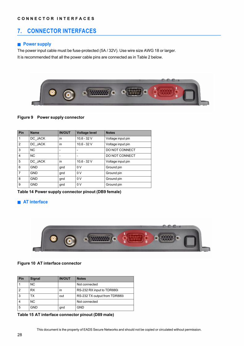
7. CONNECTOR INTERFACES
Power supplyThe power input cable must be fuse-protected (5A / 32V). Use wire size AWG 18 or larger.It is recommended that all the power cable pins are connected as in Table 2 below.
AT interface
Figure 9 Power supply connector
Pin Name IN/OUT Voltage level Notes
1 DC_JACK in 10,6 - 32 V Voltage input pin
2 DC_JACK in 10,6 - 32 V Voltage input pin
3 NC - - DO NOT CONNECT
4 NC - - DO NOT CONNECT
5 DC_JACK in 10,6 - 32 V Voltage input pin
6 GND gnd 0 V Ground pin
7 GND gnd 0 V Ground pin
8 GND gnd 0 V Ground pin
9 GND gnd 0 V Ground pin
Table 14 Power supply connector pinout (DB9 female)
Figure 10 AT interface connector
Pin Signal IN/OUT Notes
1 NC Not connected
2 RX in RS-232 RX input to TDR880i
3 TX out RS-232 TX output from TDR880i
4 NC Not connected
5 GND gnd GND
Table 15 AT interface connector pinout (D89 male)
This document is the property of EADS Secure Networks and should not be copied or circulated without permission.
28

C O N N E C T O R I N T E R F A C E S
I/O linesThe system connector is a female 26-pin high density D-connector. The signals listed in Table 4 are provided through the I/O connector. The connector geometry is Tyco 6-748481-7 compatible.
6-9 NC Not connected
Figure 11 I/O connector
Pin Name IN/OUT Voltage level Notes
1 EXT_VOUT out 10,6 - 32 V Input voltage fed from power input connector to this pin (internally fused, 2A). Max allowed current should be limited to 500 mA.
2 Reserved in N/A Reserved, do not connect
3 +5V out +5 V 5V output voltage, max 100mA load
4 GEN IO in/out TTL User configurable IO pin.
5 GEN IO in/out TTL User configurable IO pin.
6 GEN IO in/out TTL User configurable IO pin.
7 GEN IO in/out TTL User configurable IO pin.
8 GEN IO in/out TTL User configurable IO pin.
9 GEN IO in/out TTL User configurable IO pin.
10 GEN IO in/out TTL User configurable IO pin.
11 GEN IO in/out TTL User configurable IO pin.
12 GEN IO in/out TTL User configurable IO pin.
13 IN_SERVICE out TTL Tetra radio operational, active high. May require an external pull-down resistor, depending on the customer’s usage. A weak pull-down on board.
14 BSI in (2,78 V) Battery Size Indicator. Do not connect.
15 GND GND Ground pin
16 MBUS in/out (2,78 V) MBUS serial bus
17 GND GND Ground pin
18 GEN IO in/out TTL User configurable IO pin.
19 GEN IO in/out TTL User configurable IO pin.
20 GEN IO in/out TTL User configurable IO pin.
21 GPS FIX out TTL GPS fix indicator, output only, active high
22 POWER_ON_IND out TTL Device operational, active high. Left floating when device is powered off or set low (0V). (May require external pull-down resistor, depends on customer's usage.)
23 OVERTEMP out TTL Over-temperature indicator, active high. May require an external pull-down resistor, depending on the customer’s usage. A weak pull-down on board.
24 PWR_ON_OFF in TTL External Power ON/OFF control, 500 ms pulse input, active high
Table 16 I/O connector pinout (DB26 female)
Table 15 AT interface connector pinout (D89 male) (Continued)
This document is the property of EADS Secure Networks and should not be copied or circulated without permission.
29

C O N N E C T O R I N T E R F A C E S
GPS antennaThe GPS connector type is SMA female, 50 Ω. The GPS antenna connector feeds 5 VDC out from the RF connector. Therefore, do not use passive antennas because those might short circuit the DC voltage output and damage the device. The maximum load for the 5 VDC feed is 50 mA.
TETRA antennaThe TETRA connector type is TNC female, 50 Ω.
25 FBUS_RX in (2,78 V) FBUS serial bus RX line
26 FBUS_TX out (2,78 V) FBUS serial bus TX line
Figure 12 GPS antenna connector
Figure 13 TETRA antenna connector
Table 16 I/O connector pinout (DB26 female) (Continued)
This document is the property of EADS Secure Networks and should not be copied or circulated without permission.
30

T E C H N I C A L D A T A
8. TECHNICAL DATA
The following table lists the TDR880i technical specifications.
Frequency: TX 380-390 MHzRX 390-400 MHz
RF Output power EN 300392-2 compliant, power class 4 (1W)
Dimensions (w x h x d), mm 205 mm x 87 mm x 32 mm
Weight 230 g
Power supply requirements +12/+24 VDC, continuous power 24W (10.6 - 32 V)
Power consumption Note that all figures are subject to change.Device Peak Power: <20 WTETRA Call: 3,6 W, full tx power (average power)GPS: 540 mW (in addition to other power consumption when on)Idle:840 mWSleep: 600 mWShut down: <1 mW
Operating temperature -20 to +55°C
Humidity: Up to 95%, non-condensing
IP classification IP44 (splash proof)
I/O lines 16, inclusive of the various indications
Vibrations and shocks According to ETSI EN 300 019-2-5 V3.0.0 (5M3), installations only inside vehicles.According to ETSI EN 300 019-2-6 V2.1.2 (6M3)
EMC & SAR EMC approved according to 2004/108/EC.SAR is not evaluated as the device is not a handheld device.
TETRA antenna connector TNC female, 50 Ω
GPS antenna connector SMA female, 50 Ω
Data connector 9-pin D-Sub, RS-232 levels.
Parametering connector No separate connector, functionality included in the I/O connector.
I/O connector Female 26-pin high density D-connector.
Table 17 Technical data
This document is the property of EADS Secure Networks and should not be copied or circulated without permission.
31

G L O S S A R Y
9. GLOSSARY
This section explains the abbreviations that are used in this document.
AT : Attention command languageAWG : American Wire GaugeD-connector : D-shaped multi-pole connectorEMC : Electromagnetic CompatibilityEPA : ESD Protected AreaESD : Electrostatic DischargeETSI : European Telecommunications Standards InstituteFACCH : Fast Associated Control ChannelFME : For Mobile EquipmentGPS : Global Positioning SystemGTS : GPS Tracking ServerI/O : Input/outputLED : Light Emitting DiodeLNA : Low Noise AmplifierNMEA : National Marine Electronics AssociationOTA : Over-the-air TechnologyPEI : Peripheral Equipment InterfaceRF : Radio FrequencyRTC : Real-time ClockSAR : Specific Absorption RateSDS : Short Data ServiceSMA : SubMiniature version ASSI : Short Subscriber IdentityTETRA : Terrestrial Trunked RadioTNC : Threaded Neill-ConcelmanTPT : TETRA Programming ToolTTL : Transistor-Transistor LogicTX : Radio transmitterUTC : Coordinated Universal TimeVDC : Direct voltage
This document is the property of EADS Secure Networks and should not be copied or circulated without permission.
32

G L O S S A R Y
This document is the property of EADS Secure Networks and should not be copied or circulated without permission.
33

PS11021AEN
BB
01 01.02/EN