Embed Size (px)
Citation preview


TDOT - ROADWAY DESIGN GUIDELINES English Revised: 09/30/2011
3-i
SECTION III - RIGHT-OF-WAY PLANS
CHAPTER 1 - GENERAL GUIDELINES
3-100.00 ROADWAY DESIGN CHECKLIST - R.O.W. PLANS
3-102.00 SIZE OF FULL-SIZE PLAN AND CROSS-SECTION SHEETS
3-105.00 IDENTIFICATION OF SUPERVISORS, DESIGNERS, AND CHECKERS ON TITLE SHEET
3-105.05 SIGNATURES OF THE COMMISSIONER AND THE CHIEF ENGINEER ON TITLE SHEET
3-105.10 CONSULTANT'S SEAL, SIGNATURE, AND DATE ON TITLE SHEET
3-110.02 DESIGN EXCEPTION REQUESTS
3-110.05 SOILS AND GEOLOGY REPORTS
3-115.00 UPDATING SURVEYS
3-120.00 REVISIONS ON UNECONOMIC REMNANTS
3-125.00 PAVEMENT DESIGN REQUESTS
3-125.05 PAVEMENT DESIGN - SELECTED BRZE AND BR-STP
3-130.00 ABANDONMENT OF WATER WELLS
3-140.00 FIELD REVIEW PROCEDURES
3-145.00 NOTICE OF INTENT (NOI) FORM
CHAPTER 2 – DRAINAGE
3-200.00 DRAINAGE MANUAL
3-200.01 SELECTION OF PIPE MATERIALS
3-200.05 COMPARISON OF LARGE PIPES WITH BOX CULVERTS
3-200.10 BRIDGE END DRAINS
3-200.30 USE OF TRENCH OR SLOTTED DRAIN PIPE
3-205.00 END TREATMENT FOR CROSS DRAINS (UNDER MAINLINE)
TDOT - ROADWAY DESIGN GUIDELINES English Revised: 09/30/2011
3-ii
3-205.05 END TREATMENTS FOR CROSS DRAINS (UNDER PUBLIC SIDE ROADS)
3-205.10 END TREATMENTS FOR SIDE DRAINS
3-205.15 END TREATMENTS FOR MEDIAN DRAINS
3-205.20 PLACEMENT OF HEADWALLS ON CULVERTS
3-215.00 PLANS FORMAT FOR CROSS DRAINS
3-216.00 SUBMISSION OF ALL CULVERT SECTIONS
3-220.00 USE OF PIPE CULVERTS OTHER THAN "ROUND" PIPE
3-225.00 HYDRAULIC COMPUTATION RECORDS
3-230.00 IMPROVED INLET GUIDELINES
3-235.00 MANHOLES IN PAVEMENT AREA
3-236.00 COMPUTATION OF SIZE FOR CIRCULAR MANHOLES AND CATCH BASINS
3-240.00 STOCK PASSES
3-250.00 CATCH BASIN GRATE ELEVATIONS SHOWN ON THE PLANS
3-251.00 USE OF CATCH BASINS WITH STRUCTURAL STEEL GRATE UNITS
3-253.00 PERFORMANCE OF NUMBER 38, 39, 40, 42, 43 AND 44 AREA DRAINS IN SUMP CONDITIONS
3-255.00 SPACING BETWEEN CATCH BASINS FOR MAINTENANCE CLEAN OUTS
3-256.00 USE OF JUNCTION BOXES
3-260.00 ALTERNATING CATCH BASINS
3-261.00 USE OF NO. 6-72 CATCH BASINS
CHAPTER 3 - PLANS DEVELOPMENT AND CALCULATIONS
3-300.00 AREAS SHOWN IN RIGHT-OF-WAY ACQUISITION TABLE
3-300.05 EASEMENT AREAS
3-305.00 R.O.W. NOTES FOR ALL R.O.W. PROJECTS
3-305.05 R.O.W. NOTES ON PLANS REGARDING DRIVEWAYS

TDOT - ROADWAY DESIGN GUIDELINES English Revised: 09/30/2011
3-iii
3-305.06 NPDES PERMITTED PROJECTS
3-305.07 UTILITY RELOCATION NOTES ON EPSC PLANS
3-305.08 SPECIAL EPSC NOTES
3-305.10 PRIVATE DRIVEWAYS SHOWN ON R.O.W. PLANS
3-305.15 GUIDELINES ON CONSTRUCTION AND RESURFACING OF PUBLIC ROAD INTERSECTIONS AND DRIVEWAYS ON HIGHWAY PROJECTS
3-310.05 HANDICAP RAMPS
3-310.10 DRIVEWAY APRONS
3-315.00 CAPPING ROCK FILLS
3-315.05 TOPSOIL REQUIREMENTS FOR EARTHWORK BALANCES
3-315.10 SHRINKAGE AND SWELL FACTORS
3-315.15 EARTHWORK BALANCES IN PLANS
3-315.20 SUBMISSION OF GRADING QUANTITIES SHEETS
3-325.00 RAILROADS
3-330.00 PAVEMENT MARKINGS AND SIGNING ON INTERSTATE AND FULL ACCESS CONTROL ROADWAYS
CHAPTER 4 - PLANS SUBMITTALS
3-400.00 PRINTING FOR INCIDENTALS
3-400.05 PRINTING FOR "UTILITIES ONLY"
3-400.10 ADVANCE ACQUISITION PROJECTS
3-400.15 PRELIMINARY CONSTRUCTION QUANTITY ESTIMATES
3-400.20 RIGHT-OF-WAY FUNDING APPROVAL REQUESTS
3-400.25 PRINTING FOR ROW APPRAISALS AND ACQUISITION
3-400.30 DGN FILE DISTRIBUTION OF RIGHT-OF-WAY PLANS
3-400.35 ADDITION OF EROSION PREVENTION AND SEDIMENT CONTROL (EPSC) PLANS INTO FIELD REVIEW AND FINAL ROW PLANS

TDOT - ROADWAY DESIGN GUIDELINES English Revised: 09/30/2011
3-iv
3-400.40 ADDITION OF CONTOURS TO PLANS
3-405.00 RIGHT-OF-WAY REVISIONS
3-410.00 ENVIRONMENTAL PERMIT REQUIREMENTS
3-410.02 PLACEMENT OF TREES IN MITIGATION AREAS

TDOT - ROADWAY DESIGN GUIDELINES English Revised: 09/30/2011
3-9
SECTION III - RIGHT-OF-WAY PLANS
CHAPTER 1 - GENERAL GUIDELINES
3-100.00 ROADWAY DESIGN CHECKLIST - R.O.W. PLANS (See 1-105.00) 3-102.00 SIZE OF FULL-SIZE PLAN AND CROSS-SECTION SHEETS (See 2-112.00
and 4-112.00) 3-105.00 IDENTIFICATION OF SUPERVISORS, DESIGNERS, AND CHECKERS ON
TITLE SHEET (See 2-115.00) The signature block in the lower left corner of the project title sheets shall conform to the samples shown in these guidelines. 3-105.05 SIGNATURES OF THE COMMISSIONER AND THE CHIEF ENGINEER ON
TITLE SHEET (See 4-115.05)
Please refer to the appropriate Instructional Bulletin for signatures on the title sheets for lettings, right-of-way submittals, and utility submittals. 3-105.10 CONSULTANT'S SEAL, SIGNATURE, AND DATE ON TITLE SHEET When a consultant submits plans for R.O.W. Appraisals and Acquisition, the consultant's seal, signature, and date shall be placed on the right side of the title sheet above the Chief Engineer's signature. 3-110.02 DESIGN EXCEPTION REQUESTS
Despite the range of flexibility that exists with respect to the controlling elements of design, there are situations in which the accepted criteria are not applicable to the project circumstances or could not reasonably be met. For such instances, when it is appropriate, the design exception process allows for the use of criteria other than the accepted values.
The design exception process requires formal approval for exceptions relating to the
following 13 controlling criteria: (1) design speed, (2) lane width, (3) shoulder width, (4) bridge width, (5) structural capacity, (6) horizontal alignment, (7) vertical alignment, (8) grades, (9) stopping sight distance, (10) cross slopes, (11) superelevation, (12) vertical clearance, and (13) horizontal clearance (other than the clear zone).
The approval authority for design exceptions on the Interstate System or the Appalachian Development Highway System is with the FHWA Division Administrator. The approval authority for design exceptions on any other system is with the TDOT Director of the Design Division.
Design exception requests for Interstate or Appalachian Development Highway System projects shall be submitted to the FHWA Division Administrator from the Director of the Design Division.

TDOT - ROADWAY DESIGN GUIDELINES English Revised: 09/30/2011
3-10
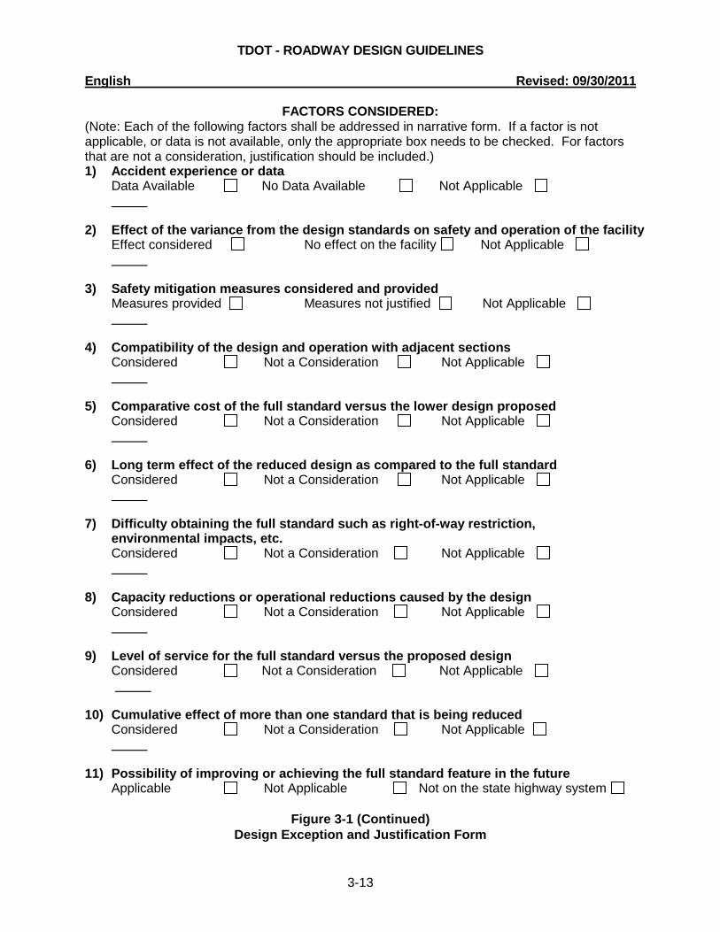
All applicable material from the following list shall be addressed in narrative form on the Design Exception and Justification Form, shown in Figure 3-1, by the Design Division, Design Manager who is responsible for the design of the project for which the design exception request is made. For locally developed projects, the highest local official responsible for the project is responsible for this task.
1. Accident experience or data.
2. The effect of the variance from the design standard on safety and operation of the facility.
3. Any safety mitigation measures considered and provided to minimize the effect of
the reduced design. 4. The compatibility of the design and operation with adjacent sections. 5. The comparative cost of the full standard versus the lower design being proposed.
6. The long term effect of the reduced design as compared to the full standard.
7. The difficulty in obtaining the full standard such as right-of-way restriction, delays,
environmental impacts, etc. 8. Any capacity reductions or operational problems caused by the proposed
exception.
9. Level of service for full standards versus the reduced design. 10. The cumulative effect of more than one standard that is being reduced. 11. The possibility of improving or correcting the reduced design feature in the future.
The completed design exception including any attachments shall be submitted to the
appropriate Assistant Director (C.E. Manager 2). The design exception will then be distributed to a Design Exception Review Committee appointed by the Director of the Design Division. The Design Exception Review Committee will review the exception and provide a recommendation regarding approval of the design exception. If necessary, the review committee will provide the Design Manager with any comments regarding the proposed exception prior to making a recommendation regarding approval of the exception.
Approved design exceptions shall be noted, with approval date, in the lower right corner of
the title sheet.

TDOT - ROADWAY DESIGN GUIDELINES English Revised: 09/30/2011
3-11
STATE OF TENNESSEE
DEPARTMENT OF TRANSPORTATION NASHVILLE, TENNESSEE 37243-1402
DESIGN EXCEPTION REQUEST AND JUSTIFICATION FORM TO: , Division Administrator, FHWA (Exceptions requiring FHWA approval) Director, Design Division, TDOT (All other exceptions) FROM: , Director, Design Division, TDOT (Exceptions requiring FHWA approval) Design Manager, Design Division, TDOT Highest Local Official Responsible for the Project, Title (Locally Developed Projects) DATE: SUBJECT: Design Exception Request Project No. Pin No. Project Description: CONTROLLING CRITERIA FOR WHICH EXCEPTION IS REQUESTED: Design Speed Lane Width Shoulder
Width Grades
Horizontal Alignment Vertical Alignment Cross Slopes
Stopping Sight Distance Superelevation Bridge Width
Horizontal Clearance (other than clear zone)
Vertical Clearance Structural Capacity
DESIGN EXCEPTION REQUESTED:
(Note: List location and controlling element of the feature an exception is requested. Example: 1) Station 4+50, 30 mph horizontal curve 2) Station 10+00 to 13+00, 11ft. lane width instead of 12ft. 3) 20 mph vertical alignment (Sag K=24) instead of 40 mph)
Figure 3-1 Design Exception and Justification Form

TDOT - ROADWAY DESIGN GUIDELINES English Revised: 09/30/2011
3-12
DESIGN DATA:
Highway Functional Classification: Standard for the Above Classification:
Existing Posted Speed: Proposed Posted Speed: Type of Terrain: Rural or Urban Area:
Traffic Data: ADT (20 ): D: ADT (20 ): T: DHV: V: DESIGN FEATURES: Standard Existing Proposed N/A Cross Slope: Superelevation: Minimum Radius of Curve: Minimum Stopping Sight Distance: Minimum "K" Value for Crest Vertical Curve: Minimum "K" Value for Sag Vertical Curve: Maximum Grade: ROADWAY TYPICAL SECTION: Standard Existing Proposed N/A Horizontal Clearance: (other than the clear zone) Shoulder Widths: Outside Shoulders: Inside Shoulders: Lane Width: BRIDGE FEATURES: Standard Existing Proposed N/A Traffic Lane Widths: Outside Shoulder Widths: Inside Shoulder Widths: Load Capacity or Sufficiency Rating: Vertical Clearance: To Waterway: To Other Highway: To Railroad:
Figure 3-1 (Continued)
Design Exception and Justification Form
TDOT - ROADWAY DESIGN GUIDELINES English Revised: 09/30/2011
3-13
FACTORS CONSIDERED: (Note: Each of the following factors shall be addressed in narrative form. If a factor is not applicable, or data is not available, only the appropriate box needs to be checked. For factors that are not a consideration, justification should be included.) 1) Accident experience or data
Data Available No Data Available Not Applicable
2) Effect of the variance from the design standards on safety and operation of the facility
Effect considered No effect on the facility Not Applicable
3) Safety mitigation measures considered and provided
Measures provided Measures not justified Not Applicable
4) Compatibility of the design and operation with adjacent sections
Considered Not a Consideration Not Applicable
5) Comparative cost of the full standard versus the lower design proposed
Considered Not a Consideration Not Applicable
6) Long term effect of the reduced design as compared to the full standard
Considered Not a Consideration Not Applicable
7) Difficulty obtaining the full standard such as right-of-way restriction, environmental impacts, etc. Considered Not a Consideration Not Applicable
8) Capacity reductions or operational reductions caused by the design
Considered Not a Consideration Not Applicable
9) Level of service for the full standard versus the proposed design
Considered Not a Consideration Not Applicable
10) Cumulative effect of more than one standard that is being reduced Considered Not a Consideration Not Applicable
11) Possibility of improving or achieving the full standard feature in the future
Applicable Not Applicable Not on the state highway system
Figure 3-1 (Continued) Design Exception and Justification Form

TDOT - ROADWAY DESIGN GUIDELINES English Revised: 09/30/2011
3-14
DESIGN EXCEPTION AND JUSTIFICATION: (Note: This section shall include a narrative description of the design exception request and includes a recommendation for approval) ATTACHMENTS: (Note: Include appropriate items such as plan prints, accident data, estimates, sketches, photos, etc.) DESIGN EXCEPTION REVIEW COMMITTEE RECOMMENDATION FOR APPROVAL: _____________________________, Assistant Director, Design Div., Region 1 and 2 _____________________________, Assistant Director, Design Div., Region 3 and 4 _____________________________, Assistant Director, Design Div., Consultant Management _____________________________, Assistant Director, Design Div., ITS, Traffic, & Standards _____________________________, Assistant Director, Design Division, Design Support
Comments Attached APPROVED: Division Administrator, FHWA Date (Director, Design Division, TDOT) cc: Quality Assurance Section
Figure 3-1 (continued)
Design Exception and Justification Form

TDOT - ROADWAY DESIGN GUIDELINES English Revised: 09/30/2011
3-15
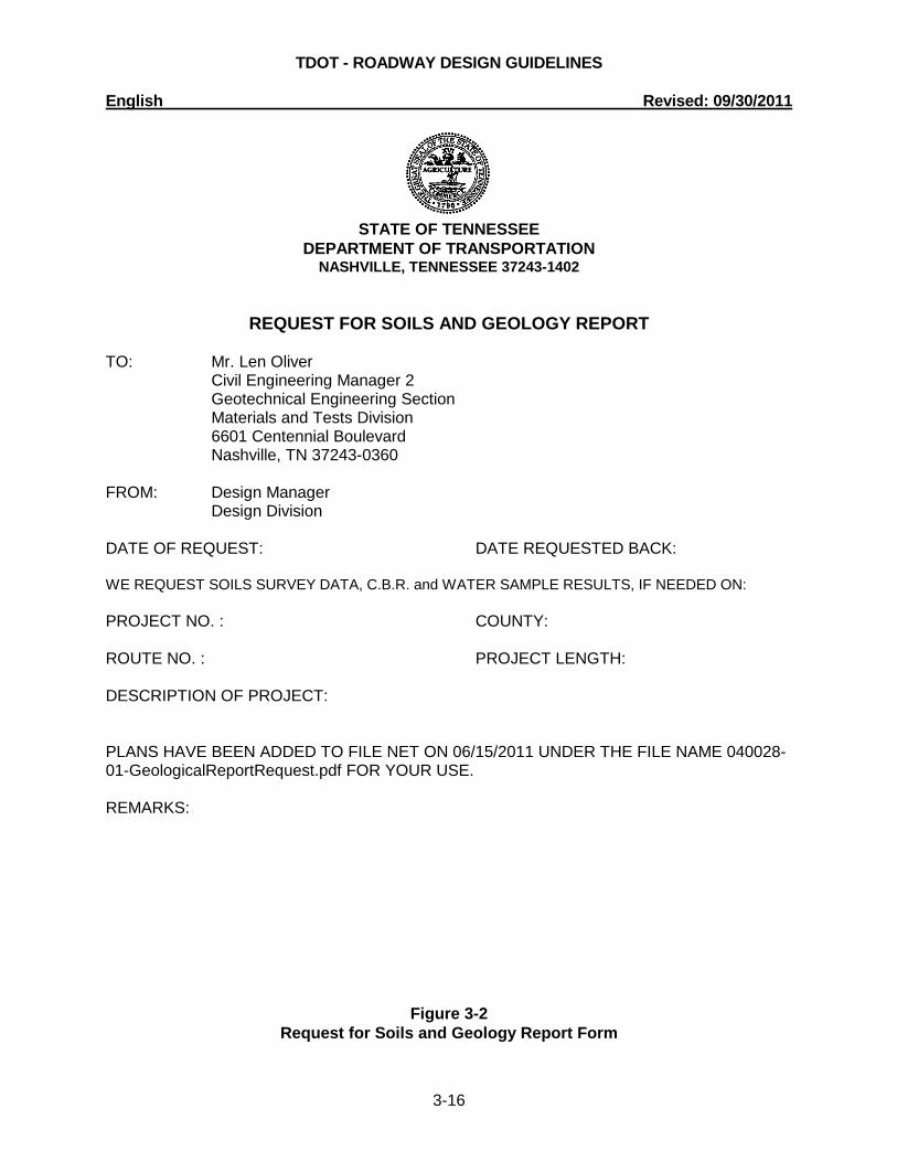
3-110.05 SOILS AND GEOLOGY REPORTS (See 3-140.00) On all projects which have grade and drain, the Soils and Geology Report shall be requested approximately one month prior to scheduling the Preliminary Field Review. A set of plans with existing contours on the present layout sheets and cross-sections should be placed on File Net. An email notice should be sent to the Geotechnical Engineering Section of the Materials and Tests Division for a Soils and Geology Report requesting a Soils and Geology Report. The email should include the Request for Soils and Geology Report Form in MS Word (*.doc) or *.pdf format included as an attachment. A copy of the email shall be placed in the project folder to document the submittal. The designer is to submit a request for C.B.R. tests, which will be needed for pavement design. If a grade or alignment change is made on the project subsequent to the submission of the plans, then replacement plan sheets and cross-section sheets are to be resubmitted. All soils data shall be incorporated into the plans prior to submission of final Right-of-Way Plans. Once soils data is added on the cross-sections, a set of plans and cross-sections should be placed on File Net. An email notification should be sent to the Geotechnical Engineering Section requesting review and approval, once the plans have been placed on File Net. A copy of the email shall be placed in the project folder to document the submittal. On projects with major geotechnical considerations, the Geotechnical Engineering Section may request the plans and/or cross-sections for review at other stages of plans development. A copy of the Request for Soils and Geology Report Form is shown in Figure 3-2.
TDOT - ROADWAY DESIGN GUIDELINES English Revised: 09/30/2011
3-16
STATE OF TENNESSEE
DEPARTMENT OF TRANSPORTATION NASHVILLE, TENNESSEE 37243-1402
REQUEST FOR SOILS AND GEOLOGY REPORT TO: Mr. Len Oliver Civil Engineering Manager 2 Geotechnical Engineering Section
Materials and Tests Division 6601 Centennial Boulevard Nashville, TN 37243-0360 FROM: Design Manager Design Division DATE OF REQUEST: DATE REQUESTED BACK: WE REQUEST SOILS SURVEY DATA, C.B.R. and WATER SAMPLE RESULTS, IF NEEDED ON: PROJECT NO. : COUNTY: ROUTE NO. : PROJECT LENGTH: DESCRIPTION OF PROJECT: PLANS HAVE BEEN ADDED TO FILE NET ON 06/15/2011 UNDER THE FILE NAME 040028-01-GeologicalReportRequest.pdf FOR YOUR USE. REMARKS:
Figure 3-2 Request for Soils and Geology Report Form

TDOT - ROADWAY DESIGN GUIDELINES English Revised: 09/30/2011
3-17
3-115.00 UPDATING SURVEYS
All additional survey information requests will be sent to the Regional Survey Supervisor responsible for the survey. An e-mail copy of the request will be forwarded to the Survey Coordinator’s Office in Headquarters.
Requests will normally take place following the Preliminary Field Review and the Right-of-Way Field Review, if necessary. Every effort will be made to make sure all additional information required is requested at these times, this will cut down on the number of times survey crews are sent out repetitively on the same project.
It is the designer’s responsibility to thoroughly review their survey information and
additional needs prior to requesting additional information from the Regional Survey Office. This will aid in minimizing multiple trips to the project by survey crews.
All requests will consist of a transmittal letter, or the use of
AdditionalSurveyRequestForm.xlt located under the TDOT Letters tab in Microsoft Excel (New), either option will include:
PIN (from PPRM) P.E. NUMBER COUNTY ROUTE PROJECT DESCRIPTION When requesting additional information, requested information will be shown either in
electronic format or on a marked set of prints. Also, it may be necessary to include GEOPAK information. This is covered in the CADD Guidelines.
If wetlands were not identified on the original survey, the location and extent of missing wetlands will be requested in one of the additional information requests. Prior to requesting additional information, that includes wetland locations; the design section will contact the environmental section and make sure wetlands have been marked. Add the date(s) of the original survey and each survey update in the lower right side of the Right-of-Way Title Sheet. 3-120.00 REVISIONS ON UNECONOMIC REMNANTS The Regional Office adding the uneconomic remnant acquisition to the plans will submit a plan change request. The parent (original) tract will be left as it appears in the acquisition table. Place the uneconomic remnant in the table separately as an 8000 series number using the parent tract number as the last digits. For example, Tract 25 would be Tract 8025. The "Total Area Acquired" column for Tract 8025 will be the area required from Tract 25 as an uneconomic remnant. In order to identify the remnant properly, it shall be specially shown on the property map and the present layout sheets with broken single cross hatching and labeled as an uneconomic remnant. If an uneconomic remnant is sold, the word "Sold" shall be added to the table of acquisition by footnote. The word "Sold", name of grantee, and date of transfer shall be placed on the property map and present layout sheets adjacent to the remnant.
TDOT - ROADWAY DESIGN GUIDELINES English Revised: 09/30/2011
3-18
3-125.00 PAVEMENT DESIGN REQUESTS (See 3-125.05)
The design of a pavement structure takes into consideration many forms of input. Several of these are traffic loadings, soil characteristics (C.B.R. tests), materials availability, construction requirements, past performance, quality control and departmental policy. Paving sections are analyzed for structural capacity and for life-cycle cost. Because of these factors, pavement designs will be set by the Pavement Design Section only. On field reviews, any comments relating to pavement sections shall be noted in the field review report and then brought to the attention of the Pavement Design Section. After reviewing the requested change with the designer, the Pavement Design Section will make the final decision on changes to be incorporated into the project plans relative to paving.
The Pavement Design Section will furnish pavement designs on projects where concrete pavement or plant mix asphalt pavement is required, except for state industrial access projects, metro-urban resurfacing projects, and 100% state resurfacing projects. For BRZE and BR-STP projects with an ADL (Average Daily Loading) of 150 or less, or an ADT (Average Daily Traffic) less than 1,000 and percent trucks less than seven, pavement sections shall be designed as in Section 3-125.05.
For all pavement design request submittals, a pavement design request packet should be e-mailed to [email protected]. A copy of the e-mail shall be placed in the project folder to document the submittal. The request will be submitted at the same time plans are submitted for preliminary field review. For projects not requiring a preliminary field review, the request shall be submitted upon completion of setting the line and grade. Each person listed in the CC section of the request for pavement design form should be copied on the email along with the design manager. The pavement design request packet shall consist of a single pdf file that contains the request for pavement design form shown in Figure 3-3, plan sheets (title, typical sections and proposed layout sheets, a traffic report which includes an ADL for the mainline and any other major roads or streets within the limits of the project and soils report once it is received should be forwarded. This information is needed to analyze the needs of side roads, overlays, pavement alternates and other pavement design features.
The naming convention for the pavement design request packet will include the PIN # and the Region #, XXXXXX-XX-PavementDesignRequest-RegX.pdf. If there are modifications, including submitting additional information, then the naming convention will be XXXXXX-XX-PavementDesign-RegX-Rev-00-00-00.pdf. Revised pavement design requests will contain the packet in its entirety - i.e. letter, plans, traffic report and soils report.
Example: 123456-00-PavementDesignRequest-Reg1.pdf
When assembling the pdf file, select small file size or default file size in Adobe Acrobat Standard in order to keep the pavement design request packet under the 15 MB email limit. If the file exceeds 15 MB, the designer should split the packet into multiple emails and add the Part 1, Part 2, etc. to the naming convention.
Example: 123456-00-PavementDesignRequest-Reg1-Part 1.pdf
For the Roadway Plans prepared by consultants, the pavement design request package should be prepared as described above and e-mailed to the Roadway Design Manager for

TDOT - ROADWAY DESIGN GUIDELINES English Revised: 09/30/2011
3-19
review. Upon acceptance, the design manager will forward the package to [email protected] . A copy of the e-mail shall be placed in the project folder to document the submittal.
The pavement design request package should be resubmitted whenever major design revisions are made that could affect the pavement design as determined by the Design Manager.

TDOT - ROADWAY DESIGN GUIDELINES English Revised: 09/30/2011
3-20
STATE OF TENNESSEE
DEPARTMENT OF TRANSPORTATION DESIGN DIVISION
PAVEMENT DESIGN SECTION SUITE 1300, JAMES K. POLK BUILDING
Nashville, Tennessee 37243-1402
REQUEST FOR PAVEMENT DESIGN DATE: DESIGNER: COUNTY: ROUTE: _______ PROJECT NO. ____ PIN: ______________ DESCRIPTION: ______________ ___________________________________________________________ PROPOSED LETTING DATE: PLEASE CHECK THE BOX FOR ALL DESIGN ITEMS THAT APPLY TO YOUR PROJECT. NEW ALIGNMENT WIDENING INTERSECTING ROADS RESURFACING DETOUR ROAD TRAFFIC TO BE MAINTAINED DURING CONSTRUCTION OTHER COMMENTS: __ ATTACHMENTS DATE REQUESTED TRAFFIC REPORT W/ADL'S _________________ SOILS REPORT _________________ PDF OF PLANS (TITLE, TYPICAL SECTIONS, PROPOSED LAYOUT) PLEASE EXPLAIN ANY MISSING ATTACHMENTS (include date requested for soils and traffic): cc: Design Manager
Figure 3-3 Request for Pavement Design Form

TDOT - ROADWAY DESIGN GUIDELINES English Revised: 09/30/2011
3-21
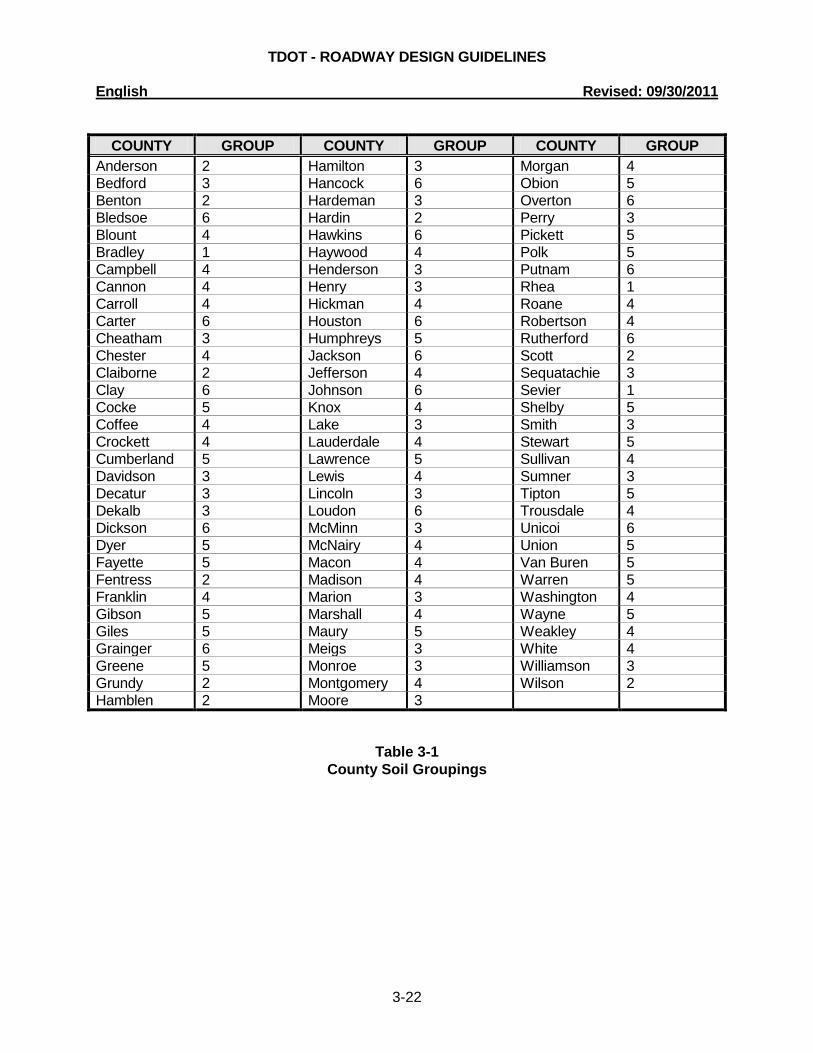
3-125.05 PAVEMENT DESIGN - SELECTED BRZE AND BR-STP (See 3-125.00) For BRZE and BR-STP projects with an ADL of less than 150, the pavement design can be obtained by using the County Soils Groupings, shown in Table 3-1, and Tables 3-2 and 3-3. ADL's will not be provided when ADT's (Average Daily Traffic) are 1,000 or less and percentage of trucks is 7% or less. In this case, use Pavement Design No. IV for ADT less than or equal to 200 and Pavement Design No. I for ADT greater than 200 but less than or equal to 1,000.
Two examples are given as follows:
The designer has a BRZE project in Hamblen County. The ADL is 53. First, go to the County Soils Groupings, Table 3-1, to obtain the Group No. which is 2. Then refer to Table 3-2, go to the column for Group 2 and down to the row containing 53 ADL. This determines that Pavement Design I shall be used. Refer to Table 3-3 to obtain the pavement design (1.25 in. "D" mix, 2.00 in. "B-M2", 3.00 in. "A" mix, and 8.00 in. "303-01"). The designer has a BRZE project in Hamblen County. The ADT is 874 and the percentage of trucks is 5. No ADL is given, because the ADT and truck percentage is low. As stated above, Pavement Design I shall be used. Refer to Table 3-3 to obtain the pavement design (1.25 in. "D" mix, 2.00 in. "B-M2", 3.00 in. "A" mix, and 8.00 in. "303-01").
When the existing road is crushed stone base only or base and double bituminous surface treatment, the roadway surface shall be replaced in kind. When the shoulders are 4 feet or less, the designer will distinguish on the field review whether the shoulder shall be stone and double bituminous surface treatment or paved with 1.25 inches of 411 D mix. The proposed roadway pavement shall be a higher type or equal surface than that of the shoulders. When using ADT's for pavement design, use design year traffic.
TDOT - ROADWAY DESIGN GUIDELINES English Revised: 09/30/2011
3-22
COUNTY GROUP COUNTY GROUP COUNTY GROUP
Anderson 2 Hamilton 3 Morgan 4 Bedford 3 Hancock 6 Obion 5 Benton 2 Hardeman 3 Overton 6 Bledsoe 6 Hardin 2 Perry 3 Blount 4 Hawkins 6 Pickett 5 Bradley 1 Haywood 4 Polk 5 Campbell 4 Henderson 3 Putnam 6 Cannon 4 Henry 3 Rhea 1 Carroll 4 Hickman 4 Roane 4 Carter 6 Houston 6 Robertson 4 Cheatham 3 Humphreys 5 Rutherford 6 Chester 4 Jackson 6 Scott 2 Claiborne 2 Jefferson 4 Sequatachie 3 Clay 6 Johnson 6 Sevier 1 Cocke 5 Knox 4 Shelby 5 Coffee 4 Lake 3 Smith 3 Crockett 4 Lauderdale 4 Stewart 5 Cumberland 5 Lawrence 5 Sullivan 4 Davidson 3 Lewis 4 Sumner 3 Decatur 3 Lincoln 3 Tipton 5 Dekalb 3 Loudon 6 Trousdale 4 Dickson 6 McMinn 3 Unicoi 6 Dyer 5 McNairy 4 Union 5 Fayette 5 Macon 4 Van Buren 5 Fentress 2 Madison 4 Warren 5 Franklin 4 Marion 3 Washington 4 Gibson 5 Marshall 4 Wayne 5 Giles 5 Maury 5 Weakley 4 Grainger 6 Meigs 3 White 4 Greene 5 Monroe 3 Williamson 3 Grundy 2 Montgomery 4 Wilson 2 Hamblen 2 Moore 3
Table 3-1 County Soil Groupings

TDOT - ROADWAY DESIGN GUIDELINES English Revised: 09/30/2011
3-23
FLEX ADLs
COUNTY SOIL GROUP NUMBER
GROUP 1 GROUP 2 GROUP 3 GROUP 4 GROUP 5 GROUP 6
1-19 I I III III III IV 20 - 29 I I I I III III 30 - 39 I I I I I III 40 - 59 II I I I I I 60 - 89 II II I I I I
90 - 119 II II II I I I 120 - 150 II II II II I I
Table 3-2
Pavement Design Number
MIX TYPE
PAVEMENT DESIGN NUMBER
I II III IV
“D” 1.25” 1.25” 1.25” 1.25”
“B-M2” 2.00” 2.00” 2.00” 2.00” “A” 3.00” 3.00” ---- ----
303-01 or 02 8.00” 10.00” 12.00” 8.00”
Table 3-3
Pavement Design
TDOT - ROADWAY DESIGN GUIDELINES English Revised: 09/30/2011
3-24
3-130.00 ABANDONMENT OF WATER WELLS If during the location and design phase it is determined that a water well requires abandonment, the Design Office shall request information at the time shown on the Project Activity Status Sheet (see 1-110.00) by notifying the Geologist Water Well Program, Division of Water Supply, 401 Church Street, Sixth Floor L & C Tower, Nashville, Tennessee 37243-1549, telephone 1-800-523-4873 or (615)532-0176. The Design Office shall also request an inspection of the well and recommendations concerning sealing. Quantities and bid items shall then be set up in the project plans for the contractor to perform the actual sealing of the well. When requesting a well inspection and recommendations for sealing from the Water Management Division, the designer shall provide the following:
1. A print of the title sheet and of the plan sheet showing the location of the well.
2. The name, address and telephone number of the driller, the date the well was drilled and the name and telephone number of the property owner at the time the well was drilled, if the information is available.
The designer shall take the initiative to ensure that this information is returned in time to
incorporate it into the project plans. The well shall be located on the proposed layout sheet and a note added as to whether the well is to be sealed by the contractor.
Every effort is to be made to ensure that this information is on the project plans before
turning them in for the letting. All water wells shall be sealed in accordance with the standards set forth by the Tennessee Department of Environment and Conservation (TDEC). 3-140.00 FIELD REVIEW PROCEDURES (See 1-120.00, 2-315.00. 2-315.05, 3-110.05
and 3-330.00)
3-145.00 NOTICE OF INTENT (NOI) FORM The Notice of Intent (NOI) is an application for the National Pollutant Discharge Elimination System (NPDES) Permit. This is required for any project which has an area of 1 acre or more disturbed by the proposed construction. The NOI form should be completed by the Storm Water Pollution Prevention Plan (SWPPP) consultant.
TDOT - ROADWAY DESIGN GUIDELINES English Revised: 09/30/2011
3-25
CHAPTER 2 – DRAINAGE
3-200.00 DRAINAGE MANUAL
In order to assist the designer performing drainage and hydrologic design, the Design Division has developed a Drainage Manual to provide a collection of applicable drainage criteria, policies and examples. The manual discusses Tennessee Department of Transportation policies, practices and procedures for performing drainage design and hydraulic analyses on projects that are the responsibility of TDOT. Designers shall use Chapters 1-11 of the Design Division Drainage Manual for all projects designed or constructed by TDOT. These chapters include:
Chapter 1 Introduction Chapter 2 General Drainage Polices and Practices Chapter 3 Drainage Plan Requirements Chapter 4 Hydrology Chapter 5 Roadside Ditches and Streams Chapter 6 Culverts Chapter 7 Storm Drainage Systems Chapter 8 Stormwater Storage Facilities Chapter 9 Energy Dissipators Chapter 10 Erosion Prevention and Sediment Control Chapter 11 Natural Stream Design Limited copies of the manual will be distributed for internal use only. Consultants and
other interested persons may download the manual from the TDOT Internet site. The manual can be found at: http://www.tdot.state.tn.us/Chief_Engineer/assistant_engineer_design/design/DrainManChap%201-11.htm 3-200.01 SELECTION OF PIPE MATERIALS See Drainage Manual, Chapter 6, Section 6.04.2 Culvert Size and Type Selection. 3-200.05 COMPARISON OF LARGE PIPES WITH BOX CULVERTS See Drainage Manual, Chapter 6, Section 6.04.2.2.2 Selection of Large Pipes vs. Box Culverts. 3-200.10 BRIDGE END DRAINS See Drainage Manual, Chapter 7, Section 7.03.6 Bridge End Drains. 3-200.30 USE OF TRENCH OR SLOTTED DRAIN PIPE See Drainage Manual, Chapter 7, Section 7.03.3.4 Use of Longitudinal Drains.

TDOT - ROADWAY DESIGN GUIDELINES English Revised: 09/30/2011
3-26
3-205.00 END TREATMENT FOR CROSS DRAINS (UNDER MAINLINE) See Drainage Manual, Chapter 6, Section 6.04.3.1.1 End Treatments for Culverts Under Mainline. 3-205.05 END TREATMENTS FOR CROSS DRAINS (UNDER PUBLIC SIDE ROADS) See Drainage Manual, Chapter 6, Section 6.04.3.1.2 End Treatments For Culverts Under Public Side Roads. 3-205.10 END TREATMENTS FOR SIDE DRAINS See Drainage Manual, Chapter 6, Section 6.04.3.1.3 End Treatments For Culverts Under Private Drives. 3-205.15 END TREATMENTS FOR MEDIAN DRAINS See Drainage Manual, Chapter 6, Section 6.04.3.1.4 End Treatments For Median Crossovers. 3-205.20 PLACEMENT OF HEADWALLS ON CULVERTS See Drainage Manual, Chapter 6, Section 6.04.3 Selection of Appurtenances. 3-215.00 PLANS FORMAT FOR CROSS DRAINS See Drainage Manual, Chapter 6, Section 6.04.1 Site Layout. 3-216.00 SUBMISSION OF ALL CULVERT SECTIONS See Drainage Manual, Chapter 6, Section 6.02 Documentation Procedures. 3-220.00 USE OF PIPE CULVERTS OTHER THAN "ROUND" PIPE See Drainage Manual, Chapter 6, Section 6.04.2.2.1 Use of Pipe Culverts Other Than Round Pipe. 3-225.00 HYDRAULIC COMPUTATION RECORDS See Drainage Manual, Chapter 6, Section 6.02 Documentation Procedures. 3-230.00 IMPROVED INLET GUIDELINES See Drainage Manual, Chapter 6, Section 6.04.3.2 Improved Inlets. 3-235.00 MANHOLES IN PAVEMENT AREA See Drainage Manual, Chapter 7, Section 7.03.5.7 Manholes in the Pavement Area.

TDOT - ROADWAY DESIGN GUIDELINES English Revised: 09/30/2011
3-27
3-236.00 COMPUTATION OF SIZE FOR CIRCULAR MANHOLES AND CATCH BASINS See Drainage Manual, Chapter 7, Section 7.03.5.5 Pipe Connections to Structures. 3-240.00 STOCK PASSES See Drainage Manual, Chapter 6, Section 6.04.3.5 Stock Passes. 3-250.00 CATCH BASIN GRATE ELEVATIONS SHOWN ON THE PLANS See Drainage Manual, Chapter 7, Section 7.03.3.6 Catch Basin Grate Stations and Elevation Shown on the Plans. 3-251.00 USE OF CATCH BASINS WITH STRUCTURAL STEEL GRATE UNITS See Drainage Manual, Chapter 7, Section 7.03.3.3.1 Use of Inlets with Structural Steel Grates. 3-253.00 PERFORMANCE OF NUMBER 38, 39, 40, 42, 43 AND 44 AREA DRAINS IN
SUMP CONDITIONS See Drainage Manual, Chapter 7, Section 7.04.4.3 Inlet Performance at Sag Points. 3-255.00 SPACING BETWEEN CATCH BASINS FOR MAINTENANCE CLEAN OUTS See Drainage Manual, Chapter 7, Section 7.03.5.6 Spacing Between Catch Basins and Manholes. 3-256.00 USE OF JUNCTION BOXES See Drainage Manual, Chapter 7, Section 7.03.5.4 Junction Boxes. 3-260.00 ALTERNATING CATCH BASINS See Drainage Manual, Chapter 7, Section 7.03.5.1.1 Alternate Catch Basins. 3-261.00 USE OF NO. 6-72 CATCH BASINS See Drainage Manual, Chapter 7, Section 7.03.5.1.2 Use of No. 6-72 Catch Basins.
TDOT - ROADWAY DESIGN GUIDELINES English Revised: 09/30/2011
3-28
CHAPTER 3 - PLANS DEVELOPMENT AND CALCULATIONS 3-300.00 AREAS SHOWN IN RIGHT-OF-WAY ACQUISITION TABLE Acquisition Areas and Easement Areas of 0.100 acres or more shall be shown in acres to 3 decimal places. Areas less than 0.100 acres shall be shown to the nearest square foot.
Right-of-way areas left and right shall be based on the centerline used for construction. If the proposed centerline is changed during design, it shall be necessary to recompute the areas left and right supplied with the survey and appearing in the TOTAL AREA columns of Figure 2-21 of the guidelines. 3-300.05 EASEMENT AREAS (See 2-320.00) 3-305.00 R.O.W. NOTES FOR ALL R.O.W. PROJECTS (See 2-300.00) 3-305.05 R.O.W. NOTES ON PLANS REGARDING DRIVEWAYS (See 2-300.05) 3-305.06 NPDES PERMITTED PROJECTS All projects which require a NPDES permit shall add the Erosion Prevention and Sediment Control (EPSC) Notes found in section 6-290.03, Erosion Prevention and Sediment Control Special Notes, NPDES and shall follow the guidance indicated in section 6-290.03 to determine if “Special Notes” are required. 3-305.07 UTILITY RELOCATION NOTES ON EPSC PLANS All projects which require utility relocations as part of the contract shall add the notes found in section 6-290.04, Erosion Prevention and Sediment Control Special Notes, Utility Relocation. 3-305.08 SPECIAL EPSC NOTES Special Erosion Prevention and Sediment Control (EPSC) Notes found in Section 6-290.00 shall be added to the first sheet of the EPSC Plans. Placement of these notes shall follow the guidance indicated in Section 6-290.00 to determine if a particular note is required. The designer should add any additional Special EPSC Notes which provide project specific information on requirements for the proposed EPSC measures, as well as specific steps the contractor is to take in the execution of the EPSC Plan. These notes should also be added to the first sheet of the EPSC Plans. Any additional Special EPSC Notes provided by the Environmental Division shall be shown on the first sheet of the EPSC Plans. 3-305.10 PRIVATE DRIVEWAYS SHOWN ON R.O.W. PLANS (See 2-300.05)

TDOT - ROADWAY DESIGN GUIDELINES English Revised: 09/30/2011
3-29
3-305.15 GUIDELINES ON CONSTRUCTION AND RESURFACING OF PUBLIC ROAD INTERSECTIONS AND DRIVEWAYS ON HIGHWAY PROJECTS
(See 2-300.10) 3-310.05 HANDICAP RAMPS Right-of-Way plans for new construction or reconstruction projects shall accommodate the appropriate curb ramp and truncated dome surface details shown on the current standard drawings. The handicap ramp standard drawings detail four (4) types or layouts of handicap ramps that can be used at intersections depending upon the site layout, topography, and right-of-way constraints. Types 1 and 2 are the preferred types to be used. Types 3 and 4 are appropriate for areas with right-of-way constraints. Designers should indicate the type ramp to be used at each intersection on the plans. Designers should use the estimated quantities for a 90 degree intersection on a 0.0% grade when calculating quantities for intersections other than 90 degrees or with grades other than 0.0%. Limits of payments for handicap ramps are shown on the standard drawings.
Ramps shall be indicated on the Right-of-Way Plans for field review. Ramps adjacent to lowered curb for driveways may be eliminated.
Truncated Domes shall be used with all handicap ramps.
Refer to the RP-H-SERIES Standard Drawings for details. 3-310.10 DRIVEWAY APRONS
Right-of-Way plans for new construction or reconstruction projects shall accommodate the appropriate driveway aprons. The driveway standard drawings have been modified to provide ADA compliant cross-slope for sidewalks through driveway aprons. The aprons have also been modified to provide for a better turning radius into the drive. 3-315.00 CAPPING ROCK FILLS
In areas where a solid rock fill is expected and grassed slopes are designed, provide road and drainage excavation (unclassified) or borrow excavation (unclassified) in sufficient quantity to cap these fills with a minimum of 9 inches +/- of common material before placing topsoil and seeding. 3-315.05 TOPSOIL REQUIREMENTS FOR EARTHWORK BALANCES (See 2-145.05 and 4-203.30) In areas to be seeded, compute the quantity of topsoil required based on a 3-inch ± thickness with a 100% shrinkage. Topsoil will not be required on projects where all slopes are to be sodded. A note shall be added to the plans detailing any other special areas where topsoil will not be required (such as rock fills not to be seeded). Do not make deductions in topsoil and seeding quantities for sodded or paved ditch areas on normal projects requiring topsoil and seeded slopes.

TDOT - ROADWAY DESIGN GUIDELINES English Revised: 09/30/2011
3-30
Topsoil shall be secured from within the proposed roadway balances where possible. If necessary, embankment areas shall be stripped in addition to excavation areas. When final earthwork balances are calculated, the topsoil shall be taken into account in the following manner:
1. Calculate the topsoil needed and the topsoil available to see if all the topsoil can possibly be obtained from the proposed roadway areas.
2. Adjust the cross-section end areas as necessary to reflect the topsoil that is to
be stripped. These adjusted areas are to be used to balance the job. 3. Balance the project using the proper shrinkage and swell factors. 4. On the profile, when showing the earthwork balance, include the topsoil figures
in the balance. See example calculations in 3-315.15. If enough topsoil cannot be obtained from the proposed earthwork areas, add a "Furnishing and Spreading Topsoil" item to the Roadway Quantity Table for the remainder. 3-315.10 SHRINKAGE AND SWELL FACTORS (See 2-145.10) 3-315.15 EARTHWORK BALANCES IN PLANS (See 2-145.05) Examples of how to calculate earthwork balances and how to show these balances on the plans profile sheet are as follows: 1. Earthwork balanced. A. Show on profile sheet. EXC. (UNCL.) COMMON 250,000 C.Y. (INCL. 13,000 C.Y. FROM EXCAVATION 295,000 C.Y. AREAS AND 5,000 C.Y. FROM EMBANKMENT AREAS; 12,500 C.Y. FROM COUNTY ROADS AND PRIVATE DRIVES) ROCK 45,000 C.Y. EXC. EMB. EMB. 253,489 C.Y. (INCL. 5,490 C.Y. FOR COUNTY ROADS AND PRIVATE DRIVES; 5,000 C.Y. TO REPLACE STRIPPED TOPSOIL) SHR. 15% SW. 15%

TDOT - ROADWAY DESIGN GUIDELINES English Revised: 09/30/2011
3-31
B. Calculation procedure for balanced section
250,000 C.Y. Exc. (Common)
-13,000 C.Y. Topsoil from exc. areas
- 5,000 C.Y. Topsoil from emb. areas
232,000 C.Y. Exc. (Common) available for balance
Exc. (Com) + [Exc. (Rock) x 1.15] vs. Emb. 1.15
232,000 + (45,000 x 1.15) vs. 253,489 C.Y. 1.15
201,739 + 51,750 vs. 253,489 C.Y. 253,489 C.Y. = 253,489 C.Y.
Balanced

TDOT - ROADWAY DESIGN GUIDELINES English Revised: 09/30/2011
3-32
2. Earthwork unbalanced. A. Show on profile sheet. EXC. (UNCL.) COMMON 350,000 C.Y. (INCL. 13,000 C.Y. TOPSOIL EXCAVATION AREAS AND 5,000 C.Y. FROM EMBANKMENT AREAS; 12,500 C.Y.FROM COUNTY ROADS AND PRIVATE DRIVES; 100,000 C.Y. EXCESS MATERIAL.) ROCK 45,000 C.Y. EXC. EMB. EMB. 253,489 C.Y. (INCL. 5,490 C.Y. FOR COUNTY ROADS AND PRIVATE DRIVES; 5,000 C.Y. TO REPLACE STRIPPED TOPSOIL) SHR. 15% SW. 15% B. Calculation procedure for unbalanced section
350,000 C.Y. Exc. (Common)
-13,000 C.Y. Topsoil from exc. areas
- 5,000 C.Y. Topsoil for emb. area
332,000 C.Y. Exc. (Common) available for balance
Exc. (Com) + [Exc. (Rock) x 1.15] vs. Emb. 1.15
332,000 + (45,000 x 1.15) vs. 253,489 C.Y. 1.15
340,446 C.Y. vs. 253,489 C.Y. The 86,957 C.Y. of excess material has had the shrinkage factor applied to it (this assumes all excess material will be common). When this quantity is multiplied by the shrinkage factor to "unshrink" it, the excess becomes 100,000 C.Y. 3-315.20 SUBMISSION OF GRADING QUANTITIES SHEETS (See 2-145.07 and 4-203.50) 3-325.00 RAILROADS (See 1-210.00, 1-210.05 and 1-210.10)
TDOT - ROADWAY DESIGN GUIDELINES English Revised: 09/30/2011
3-33
3-330.00 PAVEMENT MARKINGS AND SIGNING ON INTERSTATE AND FULL ACCESS CONTROL ROADWAYS (See 3-140.00, 4-713.05 and 4-716.13)
For interstate and full access control roadway and interchange projects, prepared by consultants, a determination should be made at the beginning of design concerning who will develop the pavement marking and signing plans. The pavement marking and signing plans will be developed by the roadway design consultant, a continuing contract consultant or the Design ITS, Traffic, and Standards Office. For interstate and full access control roadway and interchange projects, prepared by consultants, currently under design, as of June 15, 2011, the Design Manager will contact the Design ITS, Traffic, and Standards Office prior starting development of the Construction Plans for this determination. For interstate and full access control roadway and interchange projects, prepared by TDOT designers, an email notification, requesting pavement marking and signing design, should be sent to the Design ITS, Traffic, and Standards Office after preliminary plans are placed on File Net. A copy of the e-mail shall be placed in the project folder to document the submittal. The Design ITS, Traffic, and Standards Office will determine if the pavement marking and signing design will be developed by their office or by a continuing contract consultant.
Resurfacing projects on interstate and full access control roadways and interchanges are excluded from this section. For pavement marking and signing plans prepared by roadway design consultants or continuing contract consultants coordination with the Design ITS, Traffic, and Standards Office for review of the plans should be done no later than four weeks prior to the turn-in date for the roadway plans. The Design ITS, Traffic, and Standards Office should be contacted concerning any design issues that arise during the development of the pavement marking and signing plans, including the coordination of design work and structural standard drawing numbers for overhead, cantilever, or bridge mounted structures.

TDOT - ROADWAY DESIGN GUIDELINES English Revised: 09/30/2011
3-34
CHAPTER 4 - PLANS SUBMITTALS 3-400.00 PRINTING FOR INCIDENTALS Print plans for "All Incidentals Except Appraisals" if the project has more than 10 tracts. (See distribution list below.) It shall only be necessary to print the title sheet, typical sections, property maps (with Right-of-Way Acquisition Table with property owners name and county records portions completed) and the present layouts. Proposed layouts are not to be printed for incidental right-of-way work. Do not print for "Incidentals" if there are 10 tracts or less in the plans. There will not be duplicate tract numbers on any one project. During Right-of-Way Plans preparation, tracts may need to be added or deleted, but all tract numbers appearing on the preliminary plans must continue to appear on subsequent Right-of-Way Plans for the project, including the acquisition stage Right-of-Way Plans. If for any reason the tract number becomes unneeded, it must continue to be shown in the table of acquisition and on the property map and present layout sheets with the number crossed out in all places using a single line. Stamp or mark prints of title sheets for "Incidentals Only". The title sheet must have a right-of-way project number in the upper right-hand corner (not the P.E. number). This applies to all right-of-way projects to be acquired by the State. For projects whose right-of-way is to be acquired by Local Government, the preliminary engineering number is to be used in the upper right-hand corner of the title sheet. Using 0.2” lettering, ink "Right-of-way to be acquired by Local Government" on the right side of title sheet above the signatures. Incidental plans submission will not be submitted for projects whose right-of-way is being acquired by local governments. Prints for "Incidentals" 1. T.D.O.T. Regional Design Office (In house and consultant design) Prints of the plans shall be furnished to the Quality Assurance Section, Design
Standards Section as follows: 2 Sets of Half-Size State in submittal letter when prints were sent to Regional Right-of-Way Office. T.D.O.T. Regional Design Office (In-house and consultant design) Prints of the plans shall be furnished to the Regional Right-of-Way Office as follows: Region 1 10 Sets Full-Size Region 2 6 Sets Full-Size Region 3 6 Sets Full-Size Region 4 6 Sets Full-Size

TDOT - ROADWAY DESIGN GUIDELINES English Revised: 09/30/2011
3-35
2. T.D.O.T. Headquarters Design Office (In-house and consultant design) Prints of the plans shall be furnished to the Quality Assurance Section, Design Standards Section as follows:
Region 1 10 Sets Full-Size and 1 Set Half-Size Region 2 6 Sets Full-Size and 1 Set Half-Size Region 3 6 Sets Full-Size and 1 Set Half-Size Region 4 6 Sets Full-Size and 1 Set Half-Size 3-400.05 PRINTING FOR "UTILITIES ONLY" (See 2-315.00 and 2-315.05) On any project, other than a paving or resurfacing project, that does not have right-of-way acquisition involved, the designer will submit one (1) half-size sets of prints to the Quality Assurance Section, Design Standards Office to be used for utility investigation and funding by headquarters personnel. In addition, the designer will submit two (2) full-size sets of prints for each utility involved plus one (1) full-size and one (1) half-size set of prints for the regional utilities engineer to the Quality Assurance Section, Design Standards Office. These sets of prints will be used for utility investigation by the regional utilities engineer and the utilities themselves. Submission shall be made as soon as the plans are complete enough to show what work is to be done. If the Utilities Section needs a different number of prints, the designer will be advised. 3-400.10 ADVANCE ACQUISITION PROJECTS Once "Advance Acquisition" has begun, tract numbers may not be changed. 3-400.15 PRELIMINARY CONSTRUCTION QUANTITY ESTIMATES (See 4-140.00 and
4-140.05)
A preliminary construction quantity estimate shall be prepared on all projects when the funding is requested for the Final R.O.W. Plans. The Design Manager responsible for the project will place the final right-of-way plans and the quantity data on File Net and send an email notification to the Estimating and Bid Analysis Office. This submission should be done concurrently with the right-of-way funding approval request. Projects shall not be submitted for “appraisals and acquisition” or “utilities only” until the preliminary construction quantity estimate is submitted.
Each designer shall follow the procedure below to obtain the preliminary construction cost estimates:
1. Calculate preliminary quantities to a reasonable detail. Any known quantities
which cannot be estimated (example: signal and signing quantities) should be identified and included in the e-mail transmitted to the Estimating and Bid Analysis Office.

TDOT - ROADWAY DESIGN GUIDELINES English Revised: 09/30/2011
3-36
2. The TDOT designer or consultant shall provide the Design Manager responsible for the project a pdf set of the plans and the preliminary construction quantities estimate data via e-mail or CD. The estimate will contain project description information, pay item numbers, and quantities in the proper format. See section 4-140.05 for additional information. Design managers and designers shall keep a copy of the estimate data in the project folder and a copy of the estimate file.
3. If bridges, retaining walls, or other structures designed by the Structures Division
are proposed, the designer shall indicate structures are required and include the structure designer and manager on the project data portion of the estimate file. This information is necessary to insure that the structures are included in the preliminary estimate.
4. Where open-ended item numbers are used, the designer shall fill in the
descriptions in the estimate data file. Where lump sum item numbers are used, description and break down of the quantities must be submitted with the estimate data file. Without completing these item descriptions, there is no way the estimator in the Estimating and Bid Analysis Office can complete the preliminary construction cost estimate.
5. Preliminary construction quantities estimates shall be updated whenever a
revision to the plans is made that will significantly alter the project cost or every twelve (12) months until construction plans turn-in. In the event that no plan changes are made during the previous twelve month period, the Design Manager will resubmit the original data file with a request that the estimate be updated since the previous estimate is a year old.
6. For federal over-site projects, a preliminary estimate using the construction plans
quantities shall be submitted to the Estimating and Bid Analysis Office when the plans are distributed for the construction field review. A construction estimate will still be submitted with construction plans submittal in accordance with Section 4-140.00 and 4-140.05.
SUBMITTAL OF PRELIMINARY CONSTRUCTION QUANTITIES ESTIMATES
For in-house and consultant design projects, the Design Manager, or designer shall
place the final right-of-way plans and the completed construction estimate Excel on File Net. An e-mail notification should be sent to the following Groupwise e-mail address: Name: Estimates, TDOT Preliminary (User Id: JJPRELIM) once the required materials are placed on File Net. A copy of the e-mail shall be placed in the project folder to document the submittal of the preliminary construction quantities.
3-400.20 RIGHT-OF-WAY FUNDING APPROVAL REQUESTS (See 4-140.00)
Funding approval shall be requested and received on all right-of-way projects prior to their submission to be printed for “appraisals and acquisition.” The funding approval shall be requested approximately two (2) weeks prior to the anticipated right-of-way turn-in date. See Section 3-400.15 for further details.

TDOT - ROADWAY DESIGN GUIDELINES English Revised: 09/30/2011
3-37
When requesting funding approval for right-of-way “appraisals and acquisition,” send one (1) half-size print of the title sheet with right-of-way funding approval request transmittal letter, example shown in Figure 3-4, to the Program Operations Office, Federal Aid Section. Furnish a copy of the request to the Quality Assurance Section, Design Standards Office. An approved signed and dated copy of the right-of-way funding request approval transmittal letter shall be included with the Right-of-Way Project Plans turn-in assembly. See Section 3-400.25 for further details.

TDOT - ROADWAY DESIGN GUIDELINES English Revised: 09/30/2011
3-38
STATE OF TENNESSEE DEPARTMENT OF TRANSPORTATION NASHVILLE, TENNESSEE 37243-1402
MEMORANDUM TO: Programs Operations Office Attn: Federal Aid Section Suite 600, James K. Polk Bldg. Nashville, TN 37243-1402 FROM: Larry Jordan, Transportation Manager 1 Design Office, Headquarters DATE: December 30, 1999 SUBJECT: Right-of-Way Funding Approval Request Project No.: STP-13(15), 43005-2234-14, 43005-1226-04 Description: S.R. 13 from S.R. 230 to Main Street in Waverly Humphreys County
In accordance with the Roadway Design Guidelines, I am requesting funding approval for R.O.W. appraisals and acquisition. For your use, I have attached one (1) half-size title sheet of this project. At your earliest convenience following funding approval, please initial and date below and return a copy of this form to my office. Funding Approval for Right-of-Way Appraisals and Acquisition: By: __________________________
Date: __________________________
Attachment cc: ITS, Traffic, and Standards Office
Figure 3-4 Right-of-Way Funding Approval Request Transmittal Letter Example
TDOT - ROADWAY DESIGN GUIDELINES English Revised: 09/30/2011
3-39
3-400.25 PRINTING FOR ROW APPRAISALS AND ACQUISITION (See 2-315.00, 2-315.05, and 3-400.00) When submitting a project for right-of-way “appraisals and acquisition,” the Design Manager in charge of the project is to send one full-size set of the Right-of-Way Project Plans and cross-sections, a copy of the Right-of-Way Plans Request Form, three (3) CD’s with Microstation and Geopak files, and a copy of the Right-of-Way Funding Request Approval Transmittal Letter (see Section 400.20) to the Quality Assurance Section, Design Division. To insure the proper and rapid processing of Right-of-Way Plans, the following transmittal letter, shown in figure 3-5, shall accompany the Right-of-Way or Utilities Only Plans submittal to the Standards and Quality Assurance Section. The title sheet shall be plotted on 4 mil double matte finish reproducible photographic mylar. The other right-of-way sheets may be plotted on reproducible vellums or paper as directed by the TDOT Design Manager. Cross-sections shall be plotted on paper. Refer to Section 3-400.15 for preliminary construction quantity estimate. This estimate shall be completed and submitted to the Estimating and Bid Analysis Office prior to submitting plans for “appraisals and acquisition”. The date the information was submitted to the Estimating and Bid Analysis Section shall be included in the right–of-way submittal transmittal letter. It is important that the incidentals report data be incorporated into the plans before finalizing the Right-of-Way Plans to reduce right-of-way revisions. However, if it is imperative that final Right-of-Way Plans be submitted before receiving the incidentals report data, the TDOT C.E. Manager 2 will give the approval to proceed to the Design Manager in charge of the project. This approval shall be noted on the Right-of-Way Funding Request approval transmittal letter to the Program Operations Office, Federal Aid Section. See Section 3-400.00 for additional information not shown on this page. When a consultant submits plans for right-of-way “appraisals and acquisition,” the consultant’s seal, signature, and date shall be placed on the right side of the mylar title sheet above the Chief Engineer’s signature. All cross-sections will have the project number shown and be numbered in the upper right-hand project identification block. The sheet numbering will follow the numbering used on the plan sheets in the same manner used in the construction plans. Before plans are submitted for “appraisals and acquisition” of right-of-way, all information which might affect the existing or relocated utilities shall be shown on the plans. This includes, but is not limited to, the following:
1. Storm sewers, catch basins, manholes, cross drains, side drains, box culverts, channel changes, special ditches and other drainage facilities.
2. Preliminary bridge layouts and hydraulic data. 3. Retaining walls. 4. Guardrails.

TDOT - ROADWAY DESIGN GUIDELINES English Revised: 09/30/2011
3-40
5. Detour roads. 6. Traffic signal pole locations including attachment heights and footing details. 7. Street light pole locations. 8. Erosion prevention and sediment control devices (EPSC Plan) 9. Other details which might affect utilities.

TDOT - ROADWAY DESIGN GUIDELINES English Revised: 09/30/2011
3-41
STATE OF TENNESSEE
DEPARTMENT OF TRANSPORTATION NASHVILLE, TENNESSEE 37243-1402
MEMORANDUM TO: ITS, Traffic, and Standards Office, Design Division Attn: ROW Plans Submittal Suite 1300, J.K. Polk Bldg. Nashville, TN. 37243-1402 FROM: Civil Engineering Manager 1 Region 1 Design Office DATE: February 3, 2006 SUBJECT: Project No. BH-STP-131(4), 47027-2214-94 PIN 100500.00 SR 131, Bridge over Meadow Creek @ L.M. 5.78 Knox County The subject project is being submitted for right-of-way plans submittal. The following information is being forwarded to initiate printing and plans distribution: __x__ Right-of-Way Plans (20 Sheets) __x__ Cross-Sections (10 Sheets) __x__ Right-of-Way Plans Request Form __x__ CD’s Containing CADD files (3 CD’s) __x__ Right-of-Way Funding Approval Request Funding Approval Date January 31, 2006 __x__ Preliminary construction estimate quantities e-mailed to Estimating and Bid Analysis Office on January 20, 2006 Comments: 30 Full size plans, 10 Half-size plans and 6 full size cross-sections sent directly to the Region 1Right-of-Way and Utilities Office. For further information, please contact Maysoon Haddad Phone: (865) 555 - 1234. cc: Program Operations Office
Figure 3-5
Right-of-Way “Appraisals and Acquisition” Transmittal Letter Example

TDOT - ROADWAY DESIGN GUIDELINES English Revised: 09/30/2011
3-42
3-400.30 DGN FILE DISTRIBUTION OF RIGHT-OF-WAY PLANS The Department requires “CAD Plan Files Disclaimer and Limitation of Liability Agreement” forms to be submitted for distributing the files to persons outside the department in order to provide protection from unauthorized and/or potentially harmful reuse of the data contained in the files.
For security purposes the files on the CD’s will be archived (compressed, zipped, etc.) with a software program having the ability to password protect the archive and capable of making a self-extracting (.exe) file. The password should be at least eight (8) characters and/or numbers in a nonsensical sequence. Designers creating the archive will be responsible for setting the archive password and maintaining the password in the project design folder. Design managers will maintain a record of password for projects developed by consultants. The Department has available WinZip which can be loaded by IT staff for in-house designers. Consultants can find several suitable archiving programs that can be downloaded for free on the internet.
The sequence for creating CD’s is as follows: 1. Create an archive file. Archive files for utilities will be named using the State
Right-of-Way project number (i.e. 76001223104.exe). If dual counties are involved, use the project number for the county where the project begins.
2. Add the needed files. These should be the sheet layouts, the files needed to create the sheets (reference files), and cross-sections. Files created by software such as alignments (.gpk), digital terrain models (.tin), etc. need not be included.
3. Password protect the files. 4. Create a self-extracting executable file (.exe).
The CD’s and password will be submitted along with the right-of-way plans to the
Standards and Quality Assurance Section. The Standards and Quality Assurance Section will retain one (1) CD and the password and distribute two (2) CD’s and the password to the Regional Right-of-Way/Utilities Office. For regional design offices that directly submit right-of- way prints to the Regional Right-of-Way/ Utilities Office, one (1) CD and the password will be distributed to the Standards and Quality Assurance Section and two (2) CD’s and the password will be distributed to the Regional Right-of-Way/Utilities Office.
When right-of-way staking is required by regional survey personnel, the regional right-of-way office will be responsible for furnishing one copy of the files along with the staking request to the regional survey and design office.
The printed plan sheets are the Official State records and these files are for drafting purposes only. Therefore, updates to the archive files will only be made if significant changes are made to the plans (see “CAD Plan Files Disclaimer and Limitation of Liability Agreement”). The design manager will make the determination of significance and ensure that the appropriate personnel are notified of the changes.
On all Right-of-Way plans where there is either direct Railroad Involvement inside the project limits, or there is a Railroad within 200-feet of the project limits, and such project involves either Norfolk Southern Railroad (formerly Southern Railroad), CSXT Railroad

TDOT - ROADWAY DESIGN GUIDELINES English Revised: 09/30/2011
3-43
(formerly CSX), BNSF Railway Co. (formerly St. Loius and San Francisco RR), Illinois Central Railroad (ICRR) (Formerly Canadian National RR), or Union Pacific Railroad (formerly MOPAC RR), the plans shall be distributed as follows:
One (1) Half-Size Paper Copy of the plans to Railroad Coordinator at Utilities Office along with One (1) CD with the plans in PDF or Microstation Format for submission to the Railroad(s) for projects involving CSXT or Norfolk Southern. For all other projects involving railroads please submit Four (4) Half-Size Paper Copies to the Railroad Coordinator at Utilities Office. 3-400.35 ADDITION OF EROSION PREVENTION AND SEDIMENT CONTROL (EPSC)
PLANS INTO FIELD REVIEW AND FINAL ROW PLANS Erosion Prevention and Sediment Control (EPSC) Plans sheets shall be included in the plans submitted for Right-of-Way Appraisals and Acquisition. EPSC Plan sheets shall also be included in right-of-way field review and construction field review plans. EPSC Plan sheets shall immediately follow the Culvert Cross Sections. The EPSC Plan should be complete to the extent possible; however, quantity tabulations will not be required until printed for construction field review. Once plans are formally submitted, any changes to the EPSC Plan sheets due to design revision, right-of-way revision, permit requirements, mitigation requirements, ecological evaluation requirements, EPSC notes revisions, addition or deletion of sheets, etc. will require a formal plan revision. The Design Manager should contact the Technical Studies Section of the Environmental Division when EPSC Plans are revised to determine if revised plan sheets or other information is needed. 3-400.40 ADDITION OF CONTOURS TO PLANS
Contours shall be included in plans for all projects submitted for Right-of-Way Appraisal and Acquisition and Construction except for resurfacing projects, projects where a survey is not required, and small projects or projects of limited scope where a surface is not developed. Contours shall also be included in right-of-way field review and construction field review plans. Contours should include existing (pre-construction) and proposed contours. Contours for intermediate construction phases are not required. For small projects or projects of limited scope where a surface is not developed, cross sections shall be included in all plans submittals in lieu of contour sheets.
Contour sheets should be developed at the same scale as the EPSC Plan sheets.
Designers should refer to Design CADD standards for contour sheet development. Existing contours should be included on Phase 1 of the EPSC Plan or may developed as a separate sheet. Existing contour sheets will include the project centerline, contours at an interval sufficient to show the direction of flow, contour elevations, north arrow, scale, existing edges of pavement, and streams and rivers. Proposed contours should be included on the final phase of the EPSC Plan or as separate sheets. Proposed contour sheets will include the project centerline, contours at an interval sufficient to show the direction of flow, contour elevations, north arrow, streams and rivers, proposed edges of pavement, and proposed slope lines.

TDOT - ROADWAY DESIGN GUIDELINES English Revised: 09/30/2011
3-44
Proposed contours will only be required to the top of cut or toe of slope. It will not be required to connect to existing contours outside the slope lines. Surface development should include the mainline and side roads. When developed as a separate set of sheets, contours should immediately follow EPSC sheets.
Since site conditions and topography are unique to each project, designers should seek
input from the Natural Resources Office Permits Section of the Environmental Division to determine contour intervals. 3-405.00 RIGHT-OF-WAY REVISIONS (See 1-220.00) When a project has been printed for right-of-way appraisals and acquisition, and a change becomes necessary anywhere on the project, a Right-of-Way Plans revision is required. All right-of-way revisions will be submitted through the Design Manager responsible for the project in an accurate and timely manner. In the Regional Design Offices, the Design Manager responsible for the project will distribute the right-of-way revision prints to the appropriate Regional personnel. They will submit right-of-way revision prints for the appropriate Headquarters personnel through the Plans Sales Office. In the Headquarters Design Offices, the Design Manager responsible for the project will distribute the right-of-way revision prints through the Plans Sales Office. 3-410.00 ENVIRONMENTAL PERMIT REQUIREMENTS Projects involving the placement, extension or removal of pipes, bridges or culverts and/or channel changes, or other work causing environmental impacts to water bodies will require a review by the Designer. The Designer shall review the project for possible impacts to streams, drainage ways, and/or water bodies which support aquatic life at the location of the project. This review will utilize the appropriate USGS Quadrangle maps to determine if blue line streams are present and/or the ecology report that is supplied by the Technical Studies Office in the Environmental Division. For any project meeting the above criteria, Designers shall submit one half size set of Right-of-Way Field Review Plans to the Environmental Division for permit evaluation. After the Environmental Division receives both the half size set of Right-of-Way Field Review Plans and the Ecology Report, they will complete the permit evaluation. The permit evaluation shall determine the necessary permits required for the project. The findings of the permit evaluation will be documented in a report called the Permit Assessment. Consultants and Designers shall submit all submittals to the Design Manager in the Design Division for submittal to the C.E. Manager 1 in the Environmental Division. If the project does not require items submitted for permit evaluation, the Designer shall be send a letter to the Environmental Division, copied to the Program Scheduling Office, stating that no environmental impacts will occur as a result of the project.

TDOT - ROADWAY DESIGN GUIDELINES English Revised: 09/30/2011
3-45
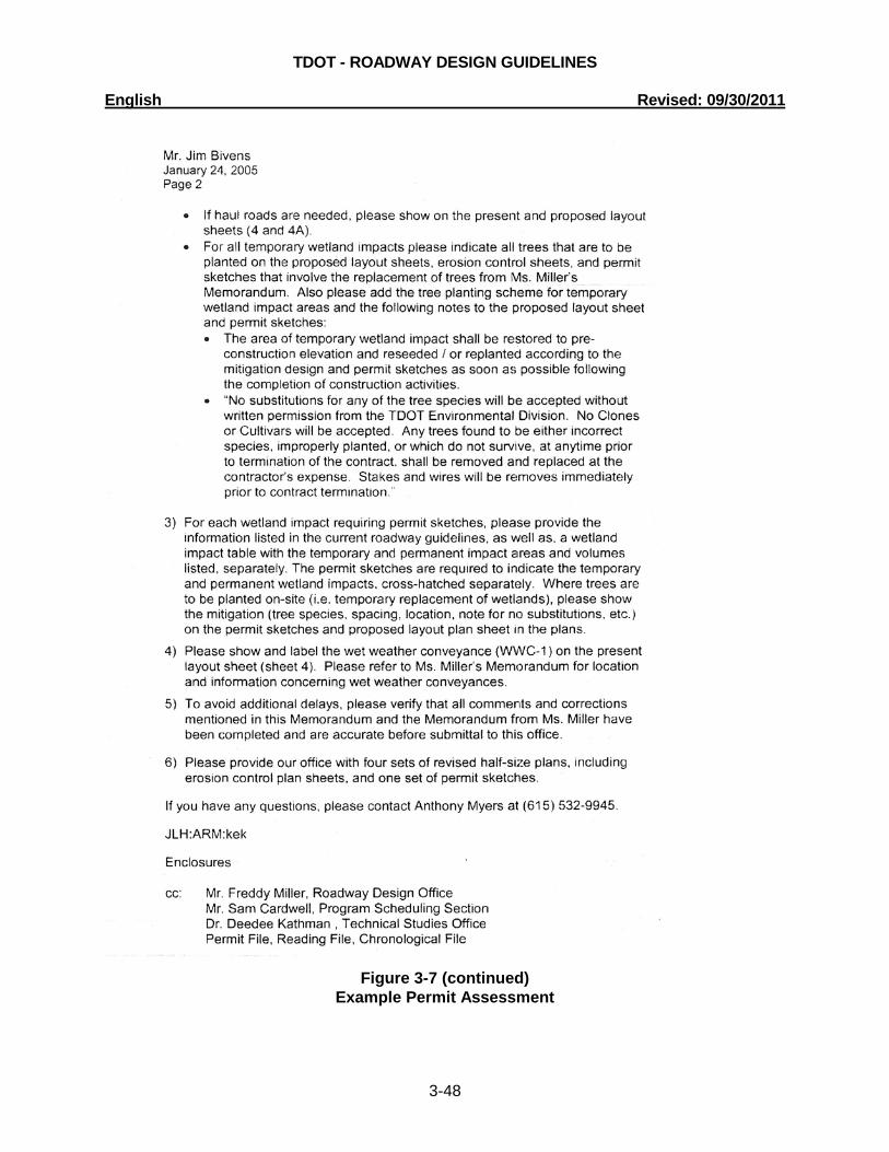
Figure 3-6 contains a flow chart depicting the steps which should be followed to complete permit application approval. Figure 3-7 is an example of a permit assessment, which has been completed by the Environmental Division and returned to the appropriate Design Manager. Along with the appropriate project and reference information, the Permit Assessment provides an itemized list of revisions and instructions for the designer to complete, which should insure prompt permit approval. Once the project has been evaluated for required permits, and the Designer receives the permit assessment, the Designer will be responsible for preparing the information and sketches required for the Environmental Division to apply for the required permits. The permit sketches and applicable information shall be submitted as indicated in the project schedule. For typical grade and drain projects permit sketches and applicable information shall be submitted approximately 146 weeks into the project. For typical bridge and approach projects the permit sketches and applicable information shall be submitted approximately 39 weeks into the project. If there is a lag in the schedule due to unforeseen delays the permit sketches and applicable information shall be submitted 12 months or 52 weeks prior to the projected letting date. The permits sketches and applicable information shall be submitted to the Natural Resource Office Permit Section for permit application.

TDOT - ROADWAY DESIGN GUIDELINES English Revised: 09/30/2011
3-46
Figure 3-6 Permitting Process Flow Chart
Does the project involve placement, extension or
removal of pipe, bridges or culverts, channel changes, or work causing environmental
impacts to water bodies?
Has Environmental Division received a set of ROW Plans
and the Ecology Report?
Send letter stating no environmental impacts will
occur as a result of the project.
Has the Designer received the permit
assessment?
Design shall submit R.O.W. Field Review Plans. (Technical Studies Office will submit
the Ecology Report and Mitigation Plan)
Has the Designer received approval of
permit sketches and all other information
submitted to Environmental Division?
Permit assessment should be received after Environmental Division receives ROW Field
Review Plans and Ecology Report.
Application for permits approved.
Resubmit revised permit sketches.
yes no
yes
yes
yes
no
no
no
END
START

TDOT - ROADWAY DESIGN GUIDELINES English Revised: 09/30/2011
3-47
Figure 3-7
Example Permit Assessment
TDOT - ROADWAY DESIGN GUIDELINES English Revised: 09/30/2011
3-48
Figure 3-7 (continued)
Example Permit Assessment

TDOT - ROADWAY DESIGN GUIDELINES English Revised: 09/30/2011
3-49
Permit Issuing Agencies Several State and Federal Agencies issue permits for impacts to Waters of the United States and Waters of the State of Tennessee. These agencies have regulatory authority over the Tennessee Department of Transportation. These agencies, and the permits the agencies issue, are described in the following paragraphs. Included are links to the agencies’ website. The following agencies issue the permits for various environmental impacts. Tennessee Department of Environment and Conservation (TDEC) The following is a link to TDEC’s permit website: http://www.state.tn.us/environment/permits/ Aquatic Resource Alteration Permit (ARAP)
Many impacts to wetlands and streams considered Waters of the State of Tennessee are covered by one of the previously issued “General” permits (road crossings, wet weather conveyances, bank stabilization, utility line crossings, etc.). Impacts to Waters of the State of Tennessee not covered by one of the General ARAP’s require an “Individual” permit. The “Individual” permit is also referred to as a “Section 401 Water Quality” permit. Typically, Individual permits are required for channel changes and wetland impacts greater than 0.25 acres of isolated wetlands or 0.1 acres of non-isolated wetlands. Individual permits require a 30 day public notice before they can be issued.
Individual Federal permits, (Corps of Engineers and Coast Guard) require a “401 Water Quality Certification” from TDEC. Typically, a 401 certification is similar to an Individual ARAP. It is usually issued under one of the federal permits that utilize the federal public notice process. This is typically required for impacts to Waters and Wetlands of the United States.
National Pollutant Discharge Elimination System Permit (NPDES)
This permit controls water pollution by regulating point sources (i.e. ditches, pipes) that discharge pollutants into Waters of the State of Tennessee. The Storm Water Pollution Prevention Plan (SWPPP) Consultant shall be responsible for completing the SWPPP document and the “Notice of Intent” (NOI), which is required when the disturbed area for a project is one acre or more.
Class V Injection Well Permit
This permit is required for any project that fills or affects stormwater runoff flowing into an open sinkhole or cave within the Right-of-Way or in the vicinity of the project. This permit is also required for any project that may affect the ground water via a sinkhole. A treatment plan may be required from the Geotechnical Engineering Section of the Division of Materials and Tests, and will need to be placed in the plans for submittal with the application for this permit. A geotechnical report may also be needed with the application for this permit.

TDOT - ROADWAY DESIGN GUIDELINES English Revised: 09/30/2011
3-50
Since a sketch is not required for this permit, the entire sinkhole must be shown on the present layout sheet of the plans. The proposed layout sheet should show the remaining portion of the sinkhole (if any) and applicable treatment.
Tennessee Wildlife Resources Agency (TWRA)
The following is a link to the TWRA’s website: http://www.state.tn.us/twra/index.html Reelfoot Watershed Management Permit
The Reelfoot Watershed Management permit is required for all projects that effects water flowing within the drainage basin of Reelfoot Lake. This permit requires a joint application to the TWRA and TDEC.
United States Army Corps of Engineers (USACE) The following is a link to the USACE’s permit website: http://www.usace.army.mil/CECW/Pages/cecwo_reg.aspx Section 404 Permit
Permits for Section 404 include environmental impact to Waters of the United States (including Waters of the State of Tennessee). The permit will either be “Nationwide” or “Individual” Permit, as describe below. Nationwide Permits This permit is required for environmental impacts to Waters of the United States (including Waters of the State of Tennessee). Many impacts are covered under previously issued general or “Nationwide” Permits (minor road crossings, categorical exclusions, bank stabilization, isolated waters and headwaters, etc.). TDEC ARAP permits are required to accompany most Nationwide Permits.
Individual Permits Impacts to streams and wetlands considered Waters of the United States (including Waters of the State of Tennessee), not covered by one of the Nationwide permits require an “Individual” permit. These are generally impacts to streams or wetlands larger than 0.5 acres. TDEC 401 Water Quality Certification is required along with the Individual Section 404 Permits.
Section 404 – Federal Emergency Management Agency (FEMA) Requirements
All projects with either the Nationwide or Individual Section 404 Permits must conform to FEMA standards. If the roadway project is located within a flood study area where either base flood elevations or a designated floodway has been determined, contact the Hydraulic Design Section of the Structures Division for further guidance and design procedures on FEMA Study information. The appropriate coordination information for Flood Study streams (i.e. “no-rise” certification and letter to corresponding officials, Conditional Letter of Map Revision

TDOT - ROADWAY DESIGN GUIDELINES English Revised: 09/30/2011
3-51
(CLOMR), FEMA map name and number, FEMA Flood Insurance Study Name, etc.), should be supplied to the Environmental Division by the Hydraulic Design Section of the Structures Division for the permit submission. Additional information is needed from the Designer when projects impact Corps of Engineers reservoirs. This is typically when TDOT is acquiring right-of-way from the Corps of Engineers. Contact the Environmental Permits Office for affected reservoir elevations. The quantities of cut and fill, in cubic yards, are required within the affected reservoir elevations. If the project causes a loss of flood storage for the reservoir, an offset plan may be required. Once the Environmental Permits Office receives this information, the Designer will be informed of the appropriate Corps of Engineers official to contact for determining if an offset plan is necessary. This may require the purchase of additional right-of-way or additional design work on the subject reservoir or route.
Section 10 Permit A Section 10 permit is required for streams considered navigable by the Corps of Engineers, but not covered by a Coast Guard Bridge Permit. With a Section 10 Permit, TDEC will require a 401 Water Quality Certification.
Coast Guard Bridge Permit The following is a link to the Coast Guard’s Bridge permit website: http://www.uscg.mil/hq/cg5/cg5411/default.asp
This permit is required for projects which impact streams or rivers deemed navigable by the Coast Guard. TDEC will require a 401 Water Quality Certification with this permit.
Tennessee Valley Authority
The following is a link to TVA’s permit website: http://www.tva.gov/river/26apermits/ Section 26a Permit
A Section 26a permit is required for all projects within the Tennessee River Watershed that may affect Waters of the United States, Waters of the State of Tennessee, and/or TVA administered public land. All impacts (except minor impacts) require a Section 26a permit which is an individual permit. Minor impacts will typically require a letter of “No-Objection” from TVA. If a Section 26a permit is required, the Hydraulic Design Section of the Structures Division shall provide an offset plan. Power storage and flood storage elevations may be obtained from the Hydraulic Design Section of the Structures Division.

TDOT - ROADWAY DESIGN GUIDELINES English Revised: 09/30/2011
3-52
Information Required for Submittal to Environmental Division for Permit Processing The Designer shall prepare the permit sketches and applicable information including half-size plans, vicinity map, a table listing the environmental impacts, and project specific permit sketches. The project specific permit sketches identified in the Project Assessment shall also include a location map. The following is a detailed list of information required for submittal to the Environmental Division for permit processing: 1) The permit assessment will indicate the number of copies of half-size plans required for
permit processing. The roadway plans shall be provided and should include:
� Cover sheet with location map � Typical sections � Present and proposed layouts, including information contained in the ecology report,
with: Cut and fill slope lines Streams and springs Wetland boundaries Proposed structures on streams Open sinkholes and caves that will be filled in, undercut, and/or receive runoff from
the project Mitigation features (meanders in proposed relocated streams, and tree plantings for
both relocated streams and wetlands, if indicated in the ecology report) Information on how in-stream work will be separated from flowing water and specific
engineering details required for the contractor to build the project � Roadway profiles � Culvert sections of all culverts on streams � Erosion prevention and sediment control plans � Detour and construction access or haul roads (if they require temporary stream or
wetland crossings) with streams 2) A vicinity map based on a color 7 ½-minute Quadrangle map, showing the stream
crossings. The vicinity map shall be on an 8 ½ × 11-inch sheet. If the Quadrangle portion showing the project is larger than that which will fit on the 8½ x 11-inch sheet, it shall be divided into 8½ x 11-inch segments and labeled with match lines. The vicinity map shall provide the following information:
� Proposed alignment � Scale shall be indicated graphically � Circle the stream crossings, and other impacts such as wetland fills, sinkholes, caves,
and structure locations � Label the station of each crossing � Label the location and stations of the project termini and the construction limits of the
roadway project � Date prepared (and date of latest revision) � Contour interval � North arrow � An information block containing the following information:

TDOT - ROADWAY DESIGN GUIDELINES English Revised: 09/30/2011
3-53
The Tennessee Department of Transportation shall be identified as the applicant The Quadrangle sheet name and number Preliminary Engineering number Project Identification Number (PIN) Route number and name Official project description County Nearest town or city
Figure 3-8 is an example Vicinity Map required for submittal with the permit sketches.
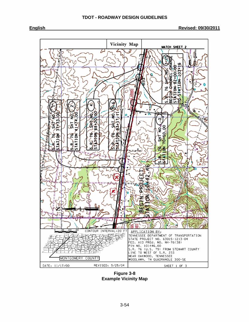
TDOT - ROADWAY DESIGN GUIDELINES English Revised: 09/30/2011
3-54
Figure 3-8
Example Vicinity Map

TDOT - ROADWAY DESIGN GUIDELINES English Revised: 09/30/2011
3-55
Figure 3-8 (continued) Example Vicinity Map

TDOT - ROADWAY DESIGN GUIDELINES English Revised: 09/30/2011
3-56
Figure 3-8 (continued) Example Vicinity Map

TDOT - ROADWAY DESIGN GUIDELINES English Revised: 09/30/2011
3-57
3) Provide a table of environmental impacts listing the following:
� Station or range of stations of impact (i.e. STA. 65+20.00 or STA. 82+00 to 103+16) � Feature impacted (wetland, channel, stream, etc.) � Specific impact on the feature (wetland fill, channel change, stream relocation, etc.)
Figure 3-9 is an example of a table listing the environmental impacts for project.
Figure 3-9 Example Table of Impacts
4) Provide permit drawings as required Site specific permit drawings will be required for certain impacts. The purpose of the drawings is to provide the regulatory agencies with details of the impacts which can then be brought to the attention of the general public via the public notice process. The drawings shall be of a nature so as not to overwhelm the non-engineering public with technical information, yet specific enough to provide details of the environmental impacts and any on-site mitigation. Specific engineering details required for the contractor to build the project shall be detailed in the plans and included with the submission of material to the Environmental Division.

TDOT - ROADWAY DESIGN GUIDELINES English Revised: 09/30/2011
3-58
Location Map
A location map will be required for all permit drawing submittals. Where multiple impacts occur within a single project, a single location map shall be utilized that indicates each specific impact requiring permit sketches. In addition to the information required on the vicinity map, the following additional information will be required on the location map:
� Project site indicated on portion of county map � County indicated on inset state map � Location of all site-specific environmental impacts shall be indicated with station number
Figure 3-10 is an example of a Location Map.
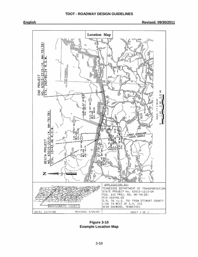
TDOT - ROADWAY DESIGN GUIDELINES English Revised: 09/30/2011
3-59
Figure 3-10 Example Location Map
TDOT - ROADWAY DESIGN GUIDELINES English Revised: 09/30/2011
3-60
General Permit Drawings
All permit drawings shall have the following general information (See “Permit Border Cell”):
� All maps and drawings shall be on 8½ x 11-inch reproducible paper � Submit the fewest number of drawings necessary to adequately show the proposed
activity. The orientation may be either portrait or landscape. � Since drawings must be reproduced by photocopying, color shading shall not be used.
Drawings may show work as dot shading, or other similar graphic symbols. Only use hatching and cross-hatching for wetland impacts.
� A 1-inch margin shall be left at the top edge and left side for binding purposes � A ½-inch bottom edge and right side border shall also be utilized � The adjacent property owner’s names and tract numbers labeled (A separate permit
drawing listing the property owner’s names, tract numbers and addresses of each impact.)
� North arrow � All drawings shall be to scale, and the scale shall be indicated graphically � Proposed Right-of-Way boundaries and all easements shown and labeled � Proposed cut and fill slope lines shown and labeled � Delete unnecessary information to avoid clutter � An information block containing the following information: Tennessee Department of Transportation shall be identified as the applicant Quadrangle sheet name and number Preliminary Engineering Number Project Identification Number (PIN) Route number and name Official project description County Nearest town or city Sheet __ of __
Additional Permit Specific Sketch Requirements:
In addition to the above general information, the following information will be required on the site specific permit drawings:
Bank Stabilization
The following information is required on permit sketches for bank stabilization:
� Station or range of stations of the impact � Plan view of bank stabilization location � Type of material to be used � Typical cross-section of the bank stabilization (to scale) � Longitudinal impact of the bank stabilization � Any other relevant features (to scale)
TDOT - ROADWAY DESIGN GUIDELINES English Revised: 09/30/2011
3-61
Channel Changes
The following information is required on permits for channel changes, alterations, or longitudinal encroachments (transitions of up to 50 ft on either end of a culvert is not included in this category):
� Station or range of stations of the impact � Plan view of the channel change showing: Location of and labeling the existing stream, relocated stream, channel
changes, alterations or longitudinal encroachments Proposed trees, meanders, deflectors, species, spacing, etc. for replacement
of channel � Typical cross-section of existing and proposed channel (to scale). The proposed
channel dimensions shall match the existing channel dimensions as closely as possible. If channel widening is needed for high flow, please contact the Technical Studies Office for an appropriate channel design. This shall also be shown on the proposed layout sheet in the plans.
� Length and size of existing open channel impacted � Length and size of existing structures along the impact � Length of relocated channel � Length and size of structures located along the channel change � Length of rip-rap and/or relevant features with the channel change. Rip-rap shall
only be used in streams where absolutely necessary and when used the evidence to support its use shall be given (to prevent erosion, velocity, etc...)
� Notes regarding in-kind replacement of trees or channel (no substitutions, etc...) � Other relevant features (to scale)
The Hydraulic Design Section of the Structures Division will perform the design
of a channel change, if the 50-year discharge exceeds 500 cubic feet per second, at the downstream section of the proposed change.
Figure 3-11 is an example of Permit Sketches required for a channel change.

TDOT - ROADWAY DESIGN GUIDELINES English Revised: 09/30/2011
3-62
Figure 3-11 Example Channel Change Permit Sketches

TDOT - ROADWAY DESIGN GUIDELINES English Revised: 09/30/2011
3-63
Figure 3-11 (continued) Example Channel Change Permit Sketches
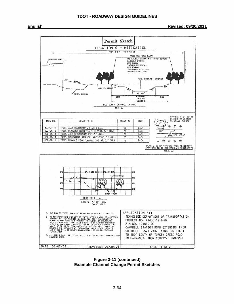
TDOT - ROADWAY DESIGN GUIDELINES English Revised: 09/30/2011
3-64
Figure 3-11 (continued) Example Channel Change Permit Sketches
TDOT - ROADWAY DESIGN GUIDELINES English Revised: 09/30/2011
3-65
Culverts longer than 200 feet
The following information is required on permit sketches for new culverts longer than 200 feet and for culvert extensions which will result in the culvert being greater than 200 feet (including the concrete aprons):
� Station or range of stations of the impact � Plan view showing: Location of and labeling of the existing and proposed culvert and extensions Proposed rip-rap (to scale) Proposed trees for in-kind replacement
� Notes regarding in-kind replacement of trees (no substitutions, etc.) � Typical cross-section of the culvert (to scale) � Other relevant features (to scale) � Table indicating: Length of existing open channel impacted Length and size of existing structures along the impact Length and size of proposed structures, concrete aprons, endwalls or
wingwalls along the impact Length of proposed rip-rap Length of tree plantings for in-kind replacement
Figure 3-12 is an example of the typical sketches required for a culvert longer
than 200 feet.

TDOT - ROADWAY DESIGN GUIDELINES English Revised: 09/30/2011
3-66
Figure 3-12 Example Permit Sketches for Culverts Longer than 200 Feet

TDOT - ROADWAY DESIGN GUIDELINES English Revised: 09/30/2011
3-67
Figure 3-12 (continued) Example Permit Sketches for Culverts Longer than 200 Feet

TDOT - ROADWAY DESIGN GUIDELINES English Revised: 09/30/2011
3-68
Endangered Species
The following information is required on permit sketches for projects involving areas of concern such as National Wild and Scenic River System, a State Scenic River, or waters designated as Outstanding National Resource Waters or projects where Endangered Species are affected or jeopardized.
� Station or range of stations of the impact � Plan view of site indicating the area of concern � Notes regarding mitigation of impact � Other relevant features (to scale)
Streams Containing Contaminated Sediments
The following information is required on permit sketches for streams containing
contaminated sediments:
� Station or range of stations of the impact � Plan view of site indicating the area containing contaminated sediments � Type of material to be used decontaminate the location � Notes regarding mitigation of impact � Other relevant features (to scale)
Wetland Impacts
The following information is required on permit sketches for wetland impacts:
� Station or range of stations of the impact � Plan view of impact area showing: Existing and proposed conditions (to scale) Cross-hatch the permanent wetland impacts and hatch the temporary
wetland impacts Construction haul/access roads Note indicating if a portion of the wetland is outside of TDOT Right-of-Way,
easements, and/or not to be disturbed during construction � Profile view of impact area showing existing and proposed conditions (to scale) � Boundaries of the existing wetland shall be indicated even if the wetland extends
past the Right-of-Way or easement lines � Notes regarding mitigation (tree, species, etc...) of temporary wetland
replacement as indicated in the ecology report (also, shown on proposed layout sheet in plans)
� Table indicating: Legend of hatching for the permanent and temporary wetland impacts Area of the permanent and temporary wetland impacts in acres Volume of the permanent and temporary wetland impacts in cubic yards
Figure 3-13 is an example of the typical sketches required for wetland impacts.

TDOT - ROADWAY DESIGN GUIDELINES English Revised: 09/30/2011
3-69
Figure 3-13 Example Permit Sketches for Wetland Impacts

TDOT - ROADWAY DESIGN GUIDELINES English Revised: 09/30/2011
3-70
Figure 3-13 (continued) Example Permit Sketches for Wetland Impacts

TDOT - ROADWAY DESIGN GUIDELINES English Revised: 09/30/2011
3-71
Figure 3-13 (continued) Example Permit Sketches for Wetland Impacts

TDOT - ROADWAY DESIGN GUIDELINES English Revised: 09/30/2011
3-72
Figure 3-13 (continued) Example Permit Sketches for Wetland Impacts

TDOT - ROADWAY DESIGN GUIDELINES English Revised: 09/30/2011
3-73
Application For Permit Approval
Once the Application for Permits is approved and submitted to the regulatory agency (TDEC, TVA, etc…) by the Environmental Division, an e-mail will be sent to the Design Manager. Please note, if the regulatory agency disagrees with the Environmental Divisions assessment, the regulatory agency will request more information.
Figure 3-14 is an example e-mail that will be sent to the Design Manager.
PE # 39945-1679-04 PIN 104395.00 SIA - Mt. Ararat Road Serving Beech River Airport Henderson County Our office reviewed the above referenced project for a permit assessment (Activity 670-PPRM) and application (Activity 675-PPRM). We applied for Water Quality Permits on November 28, 2005 and no further information is needed at this time. If the regulatory agencies have specific requests, we will notify your office, as soon as possible, for any additional information that may be needed. If the plans change from the date of application, in areas shown as a stream on the quad map or listed as a stream in the ecology report dated July 22, 2005, please notify our office, as soon as possible, for further review.
Figure 3-14
Example Approved Application for Permits Notification E-Mail

TDOT - ROADWAY DESIGN GUIDELINES English Revised: 09/30/2011
3-74
Table 3-4 identifies typical project activities for the permitting process required for a typical three mile grade and drain project with some environmental concerns. Table 3-5 identifies project activities for the permitting process required for a typical bridge and approach project. Some of the activities have designated Activity Numbers as designated in the Program Project and Resource Management Activities Manual. Please note the number of weeks may very per project due to unforeseeable delays. Activities which are identified in the Program, Project, and Resource Management Activities Manual are designated in Tables 3-4 and 3-5.
Grade & Drain Project Week
No.
Design Division Description of Activity
Other Divisions Description of Activity
0 Design Begins. (Begin Activity No. 340)
6
Designer sends plans to Structures Division for Grade Approval and to Environmental Division for locating Environmental Boundaries and to distribute plans to SWPPP Consultant. (End of Activity No. 340)
7 Environmental Division to send Plans to SWPPP Consultant.
11 Structures Division sends Grade
Approval to Design Division. (Activity No.345)
15
SWPPP Consultant to send Design Division information concerning highly impaired waters (if such are on project).
17
Design Manager Distributes Preliminary PS&E Field Review Plans and for Technical Studies. (Activity No. 365)
18
Environmental Division starts reviewing plans for natural resources impacts etc. (Beginning of Activity No. 370) and sends Preliminary PS&E Plans to SWPPP Consultant.
21* Design Manager Conducts Preliminary PS&E Field Review. (Activity No. 375)
SWPPP Consultant to provide comments at Preliminary PS&E Field Review.
Table 3-4
Typical Grade and Drain Project Timeline Including Permit Activities Note: Number of weeks may vary.
* indicates project milestones

TDOT - ROADWAY DESIGN GUIDELINES English Revised: 09/30/2011
3-75
Grade & Drain
Project Week No.
Design Division Description of Activity
Other Divisions Description of Activity
23 Design Manager Distributes Preliminary PS&E Field Review Report. (Activity No. 390)
24
Environmental Division ends reviewing plans for natural resource impacts and provides: “Environmental Boundaries and Avoidance memoranda” to Design, Geotechnical and Structures Divisions. (End of Activity No. 370)
33* Design Office Conducts Design Meeting. (Activity No. 400)
44
Design Manager reviews Hearing Transcript & prepares Response Letter. Design Director reviews and approves Response Letter. Design Manager distributes Response Letter. Design Manager notifies Environmental Division of any alignment changes. (Activity No. 410)
45
Environmental Division revises Environmental Document for any alignment changes and does any required field work necessary due to alignment shift.
53
Designer Completes ROW Plans Preparation (End of Activity No. 535) and Design Manager Distributes ROW PS&E Field Review Plans to Environmental Division for Environmental Permit Evaluation.
54
Environmental Division Receives ROW PS&E Plans to develop Mitigation Plans (Activity No. 565) and sends ROW PS&E Plans to SWPPP Consultant.
Table 3-4 (continued)
Typical Grade and Drain Project Timeline Including Permit Activities Note: Number of weeks may vary.
* indicates project milestones

TDOT - ROADWAY DESIGN GUIDELINES English Revised: 09/30/2011
3-76
Grade & Drain
Project Week No.
Design Division Description of Activity
Other Divisions Description of Activity
56* Design Manager Conducts ROW PS&E Field Review. (Activity No. 540)
SWPPP Consultant attends ROW Field Review.
60 SWPPP Consultant to send
comments concerning EPSC Plan Sheets to the Design Division.
64 Designer to respond to all of comments from SWPPP Consultant.
67 Designer begins Finalizing ROW Plans. (Beginning of Activity No. 585)
Environmental Division prepares Final Mitigation Plan. (Activity No. 570)
72 Designer Finalizes ROW Plans. (End of Activity No. 585)
77
Designer Begins Refining ROW Plans. (Beginning of Activity No. 588)
Environmental Division Distributes Permit Assessment, with permit locations, and final mitigation design to Design Division. (Activity No. 670)
80*
Design Manager Distributes Final ROW and/or Utility Plans and Preliminary Estimate. (Activity No. 600)
146
Design Manager Submits Permit Sketches and Plan Sheets to Environmental Division. (End of Activity No 575) (** If there is a lag in the schedule due to other issues this should take place 12 months or 52 weeks prior to Letting Date)
147
Environmental Division to begin review of Permit Sketches and Plan Sheets and makes any request for adjustment to the appropriate Design Manager of Project. (Beginning of Activity No. 675)
Table 3-4 (continued)
Typical Grade and Drain Project Timeline Including Permit Activities Note: Number of weeks may vary.
* indicates project milestones

TDOT - ROADWAY DESIGN GUIDELINES English Revised: 09/30/2011
3-77
Grade & Drain
Project Week No.
Design Division Description of Activity
Other Divisions Description of Activity
159
Environmental Division to apply for Permits (End of Activity No. 675) notifies Design Division via email. (**If there is a lag in the schedule to other issues this should take place 9 months or 39 weeks prior to Letting Date)
180 Design Manager Distributes Construction PS&E Field Review Plans. (End of Activity No. 705)
Environmental Division sends Construction PS&E Plans to SWPPP Consultant.
183 Design Manager Conducts Construction PS&E Field Review. (Activity No. 710)
SWPPP Consultant comments concerning EPSC Plans to be included in report.
183
Design Manager informs Environmental Division (Permits) of any changes resulting from Construction PS&E Field Review that would require a permit application revision.
185 Design Manager to Distribute Construction PS&E Field Review Report.
Environmental Division Obtains Permits. (End of Activity No. 680)
189
Design Manager Submits Final Roadway Plans (mylars) w/estimate to Program Operation Office, Estimate Section. (End of Activity No. 715)
Environmental Division sends Final Roadway Plans to the SWPPP Consultant for the completion of the SWPPP.
198* CONTRACT LETTING
Table 3-4 (continued) Typical Grade and Drain Project Timeline Including Permit Activities
Note: Number of weeks may vary. * indicates project milestones

TDOT - ROADWAY DESIGN GUIDELINES English Revised: 09/30/2011
3-78
Bridge & Approach
Project Week No.
Design Division Description of Activity
Other Divisions Description of Activity
0 Design Begins. (Begin Activity No. 340)
6
Design Manager sends Preliminary Plans to Structures Division for Grade Approval and to Environmental Division to distribute plans to SWPPP Consultant. (End of Activity No. 340)
7 Environmental Division to send Plans to SWPPP Consultant.
11 Structures Division sends Grade
Approval to Design Division. (Activity No. 345)
15
Design Division sends Preliminary Plans (that have received Grade Approval from Structures Division) to Environmental Division for Technical Studies. (Activity No. 365)
20
Environmental Division conducts technical studies to verify environmental boundaries, wetlands, hazardous material, biological concerns, mitigation measures and/or commitments in plans are consistent with environmental document. Environmental Division provides Environmental Boundaries & Avoidance Memo. (Activity No. 370)
23 Structures Division provides
Preliminary Bridge Layout to the Design Division. (Activity No. 490)
25
Design Division distributes ROW Plans for Preliminary/ROW PS&E Field Review and to the Environmental Division for the permit assessment process and for the SWPPP Consultant.
Table 3-5
Typical Bridge and Approach Project Timeline Including Permit Activities Note: Number of weeks may vary.
* indicates project milestones

TDOT - ROADWAY DESIGN GUIDELINES English Revised: 09/30/2011
3-79
Bridge & Approach
Project Week No.
Design Division Description of Activity
Other Divisions Description of Activity
28*
Design Division conducts PREL/ROW PS&E Field Review. (Activity No. 540)
SWPPP Consultant to provide comments on the EPSC Plans Sheets to be included in PS&E Field Review Report.
30 Design Manager Distributes Preliminary/ROW Field Review Report.
31 Environmental Division sends “Permit
Assessment Report” to the Design Division. (Activity No. 670)
35*
Design Division distributes Final ROW and/or Utility Plans and Preliminary Estimate. (**this milestone is contingent on getting authorization for Right-of-Way Funding) (Activity No. 600)
39
Design Division submits Permit Sketches and Plan Sheets to the Environmental Division. (Activity No. 575)
40
Design Division prepares Construction Plans. (Activity No. 705)
Environmental Division to begins Review of Permit Sketches and Plan Sheets and makes any request for adjustment to the appropriate Design Manager of Project.
46 Environmental Division to apply for
Permits and notifies Design Division via email. (Activity No. 675)
50 Design Division distributes Construction PS&E Prints.
Environmental Division sends Construction PS&E Plans to SWPPP Consultant.
53 Design Manager Conducts Construction PS&E Field Review. (Activity No. 710)
SWPPP Consultant comments concerning EPSC Plans to be included in Field Review Report.
Table 3-5 (continued)
Typical Bridge and Approach Project Timeline Including Permit Activities Note: Number of weeks may vary.
* indicates project milestones

TDOT - ROADWAY DESIGN GUIDELINES English Revised: 09/30/2011
3-80
Bridge & Approach
Project Week No.
Design Division Description of Activity
Other Divisions Description of Activity
53
Design Manager informs Environmental Division (Permits) of any changes from Construction PS&E Field Review that would require a permit application revision.
55 Design Manager to Distribute Construction PS&E Field Review Report.
Environmental Division Obtains Permits. (Activity No. 680)
61
Design Manager submits Final Roadway Plans (mylars) w/estimate to Program Operation Office, Estimate Section.
Environmental Division sends Final Roadway Plans to the SWPPP Consultant for the completion of the SWPPP.
70* CONTRACT LETTING
Table 3-5 (continued) Typical Bridge and Approach Project Timeline Including Permit Activities
Note: Number of weeks may vary. * indicates project milestones
Permit Drawing Cells
The following cells shall be used for permit drawings and can be found in the TDOT Design Division’s standard cell libraries (STDS.CEL):
• PMLOCP Permit drawing location map form (portrait)
• PMLOCL Permit drawing location map form (landscape) • PMSK Permit drawing sketch form (portrait) • PMSKGR Permit drawing sketch form (landscape with profile grid)
These cells can be accessed through the TDOT Design Division MicroStation© interface on the “Permits and Forms” dialog. This dialog can be brought up through the TDOT drop down menu on the MicroStation© title bar.
The latest versions of the standard cell libraries and programs to access them can be obtained on TDOT Design Division’s CADD web page at:
http://www.tdot.state.tn.us/Chief_Engineer/assistant_engineer_design/design/v8/v8design.htm

TDOT - ROADWAY DESIGN GUIDELINES English Revised: 09/30/2011
3-81
Plans Distribution Notification to the Environmental Division
For all projects requiring permits Table 3-6 shows the Environmental Division units that need notification that plans have been placed on FileNet.
1. Email notification at major milestones will include an email to the Director of the
Environmental Division, Suite 900, James K. Polk Building. Refer to Table 3-6 for additional units in the Environmental Division that should be notified. This will eliminate printings and distributions for permit assessments and technical studies including archaeological, ecological, historical, and hazardous waste purposes.
2. The right-of-way field review plans shall include the proposed EPSC plan sheets.
Quantity tabulations are not needed for the field review plans. 3. The plans submitted for permit application purposes shall include mitigation plans
and EPSC sheets. 4. The Environmental Division will be responsible for requesting final construction
plans from the print shop after plans are submitted.
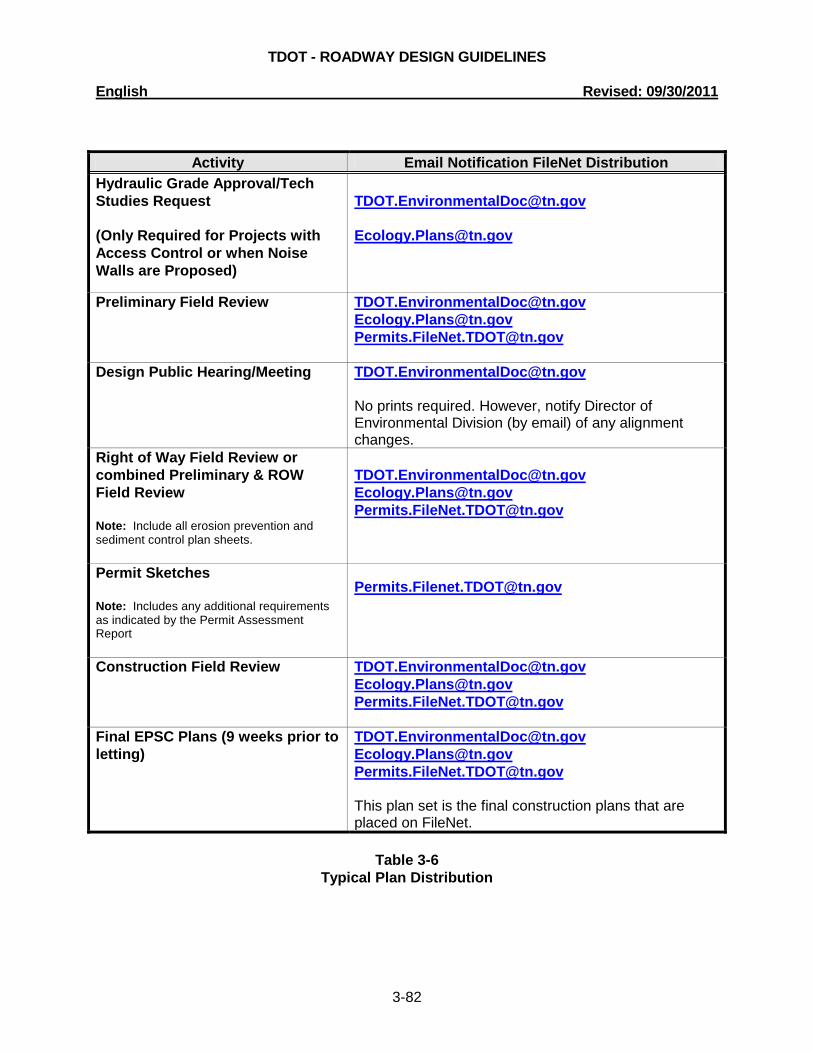
TDOT - ROADWAY DESIGN GUIDELINES English Revised: 09/30/2011
3-82
Activity Email Notification FileNet Distribution Hydraulic Grade Approval/Tech Studies Request (Only Required for Projects with Access Control or when Noise Walls are Proposed)
[email protected] [email protected]
Preliminary Field Review
[email protected] [email protected] [email protected]
Design Public Hearing/Meeting [email protected] No prints required. However, notify Director of Environmental Division (by email) of any alignment changes.
Right of Way Field Review or combined Preliminary & ROW Field Review Note: Include all erosion prevention and sediment control plan sheets.
[email protected] [email protected] [email protected]
Permit Sketches Note: Includes any additional requirements as indicated by the Permit Assessment Report
Construction Field Review
[email protected] [email protected] [email protected]
Final EPSC Plans (9 weeks prior to letting)
[email protected] [email protected] [email protected] This plan set is the final construction plans that are placed on FileNet.
Table 3-6
Typical Plan Distribution

TDOT - ROADWAY DESIGN GUIDELINES English Revised: 09/30/2011
3-83
3-410.02 PLACEMENT OF TREES IN MITIGATION AREAS Areas designated for tree planting for water quality impacts typically include restored or existing wetlands, channel changes, and when specified, areas around streams and the inlet and outlet areas at culverts. The Technical Studies Office in the Environmental Division shall be consulted to determine which areas require tree planting. All required tree planting must be located within the permanent right-of-way rather than in a drainage easement. Sufficient room shall be designated for the placement of trees and seedlings near culverts, channel relocations and along stream banks, or other mitigation features, within the right-of-way boundaries. These trees should be protected from disturbance during construction and from maintenance activities after construction. Within the approved permit, the regulatory agencies will specify how long and what percentage of survival is needed to satisfy the conditions of the specific permit.
All notes required by the Technical Studies Office, Environmental Division, or specified in the Ecology report must be placed in the final ROW plans for the permit applications.