Embed Size (px)
Citation preview
TDMA SATCOM & Operational Architecture for 1ST & 2ND SBCT,
CJTF-76, & 3ID.
10th International Command and Control Research Technology Symposium
June 13-16 2005
CPT Corey PressleyBattle Command Battle Laboratory-Gordon706-791-5515 DSN [email protected]

Agenda• Problem Statements• Stryker Brigade Combat Team (SBCT)• Fundamentals of TDMA SATCOM• Network Management• TDMA Architectural Solutions (SBCT & 3ID)• Equipment in system• Future Projects
General Problem Statement• The SBCT, CJTF-76, 3ID needed a method that provided sufficient
data rates to support Battlefield Collaboration, Situational Awareness, and Data Imagery between battalion and brigade TOCs. – Beyond Line of Sight (BLOS)– High Data Throughput– Bandwidth Efficient– Easily Transportable– Transmission Security

SBCT Background• 3/2 Infantry chosen for OIF rotation (o/a 1 November 2003)• 3/2 Infantry employs NTDR (surrogate JTRS) for TOC-TOC communications• Bandwidth shortfall issue raised during 3/2 Infantry CERTEX (May 03)• Range between TOCs is exceeds 5Km(which is determine as the effective range in foliage.• NTDR issues:
– Throughput (roughly equivalent to 28.8 kbps modem)• Currently did not support SA data
– Common Operational Picture (COP) FBCB2– Required use of relays (C2 protect issue)– Range (~ 5 Km in foliage)
• PEO C3T SPO/PM WIN-T/RDEC/ BCBL(G) partnered on TDMA solution.– Operational Needs Statement generated from 3/2 Infantry– Supports C2, collaboration, and ABCS traffic.– Uses Linkway 2100 modem and VSAT (13 nodes)
• Current status:– Equipment procured, integrated and trained at Fort Lewis Sept/Oct 03.– PEO Team in Kuwait during RSOI for in-theater training.– 90 day effort resulted in 13 nodes delivered to 1SBCT for OIF-III– TDMA network up and operational in northern Iraq– 2SBCT has replaced 1SBCT (October 04)

Fundamentals of TDMA
• TDMA - Time Division Multiple Access– A digital transmission technology that allows a number of users to
access a single radio-frequency (RF) carrier without interference by allocating unique time slots to each user within each carrier.
• TDMA: Users are separated by time
• TDMA DAMA – TDMA Demand Assigned Multiple Access– TDMA technology where time slots are dynamically assigned based
on user demand for services.
• MF-TDMA DAMA – Multi-frequency TDMA DAMA– TDMA technology where multiple carriers on a spacecraft can be
allocated to a TDMA network.– Forms a “bandwidth pool” for user to share dynamically.

2 ea. 2048 kbps full duplex point to point linksTransmit on one carrier frequency and receive on another8 MHz of bandwidth utilized at all timesNo dynamic allocation of bandwidthScales poorlyCarriers are full duty cycle regardless of user demand for bandwidth
No user demand for bandwidth User demand for bandwidth exists
FDMA Spectrum Plots

•Single 5 Msymbol/sec carrier defined•No user demand for bandwidth from any of nodes in the TDMA network•No bandwidth allocated.
•Single 5 msymbol/sec carrier defined•Demand for bandwidth exists, hence, bandwidth is allocated accordingly. •Additional carriers can be defined to support network growth.•User’s share carrier(s) for both transmit and receive•Scales well – efficient use of valuable space resource•Supports ad hoc networking well
No user demand for bandwidth User demand for bandwidth existsTDMA-DAMA Spectrum Plots
FIG A FIG BFIG A
FIG B

TDMA Management
• TDMA network requires Master Reference Terminal (MRT) site
• Alternate MRT (AMRT) site can optionally be used for failover
• MRT roles:– Network node definition– Node to node connectivity– Bandwidth on demand allocation

Linkway Network Components
TDMA
Linkway
Traffic Terminal
Linkway
NCC1 NMS
Linkway
MRT Site
LAN
Linkway
NCC2 NMS
Linkway
Alternate MRT Site
LAN
Linkway
Traffic Terminal
Linkway
Traffic Terminal
Linkway
Traffic Terminal

Linkway 2100 TDMA Modem
• Market leader (full/partial mesh) is Linkway 2100 product
• Multi-protocol satellite modem (ATM/IP/Frame/ISDN)– Protocols operate independent of each other– Discrete symbol rates (5, 2.5, 1.25, .625, and .312 Msymbols/sec)
• Requires a Network Control Center(NCC) at one of the nodes in the network
– Co-located at the Master Reference Terminal (MRT)– Defines traffic terminals in the network– Defines node connectivity– Allocates bandwidth– Alternate NCC can be defined for redundancy

Traffic Terminal portion of MRT stack
Management portion of MRT stack
Master Reference Terminal Electronics

Sample TDMA Network loading chart
Traffic Bursts
Reference BurstsSignaling BurstsAcquisition BurstsControl BurstsTraffic Bursts
Guard Bands

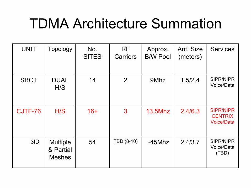
TDMA Architecture Summation
SIPR/NIPR Voice/Data
(TBD)
2.4/3.7~45MhzTBD (8-10)54Multiple & Partial Meshes
3ID
SIPR/NIPRCENTRIX Voice/Data
2.4/6.313.5Mhz316+H/SCJTF-76
SIPR/NIPR Voice/Data
1.5/2.49Mhz214DUAL H/S
SBCT
ServicesAnt. Size (meters)
Approx. B/W Pool
RF Carriers
No. SITES
TopologyUNIT

THEATERNETWORK DIV MSE
Ku BAND SATELLITE
HC
LOS
X X
DMAIN
l l l ll l
X
BDE FWD (TOC B)
l l
X
BDE MAIN (TOC A)
X
BSA
BRSS
BSN
BSN
HC
LOS
SMART-T
SMART-T
MILSTARMDR
OBJECTIVE 3-2 SBCT DEPLOYMENT COMMUNICATIONS ARCHITECTUREWITH DIGITAL RANGE EXTENSION ASSESTS DEPLOYED TO BATTALION LEVEL
WITH A TDMA Ku BAND SATTELITE SOLUTIONPOC FOR THIS DOCUMENT:
JEREMY BRADY EMAIL: [email protected] Projects Office (SPO), PEOC3T, Fort Monmouth, NJ
SMART-T
2.4m Ku-BANDTERMINAL
(MRT)
BDE CDR/ TAC
l l
1.5m Ku-BANDTERMINAL
(TT)
SPARETERMINAL
1-23 IN 2-3 IN 5-20 IN 1-14 CAV
l l
3-17 CAV
1-37 FA
I I
CSB
44 CSB
1.5m Ku-BANDTERMINAL
(TT)
1.5m Ku-BANDTERMINAL
(TT)
1.5m Ku-BANDTERMINAL
(TT)
1.5m Ku-BANDTERMINAL
(TT)
1.5m Ku-BANDTERMINAL
(TT)
1.5m Ku-BANDTERMINAL
(TT)
1.5m Ku-BANDTERMINAL
(TT)
1.5m Ku-BANDTERMINAL
(TT)
1.5m Ku-BANDTERMINAL
(TT)
1.5m Ku-BANDTERMINAL
(TT)
Camp Doha
2.4m Ku-BANDTERMINAL
(MRT)
Sanctuary

Camp Doha 2.4m Reachback Antenna

Brigade Main 2.4m Antenna

Traffic Terminal 1.5m Antenna

Traffic Terminal portion of MRT stack
Management portion of MRT stack
Master Reference Terminal Electronics

Linkway 2100 modem
Cisco 1760 VPN router
KG-175 Taclane
Cisco 3725 Router
PA power supply
Storage drawer
UPS
Traffic Terminal Electronics
TDMA Architecture Summation
SIPR/NIPR Voice/Data
(TBD)
2.4/3.7~45MhzTBD (8-10)54Multiple & Partial Meshes
3ID
SIPR/NIPRCENTRIX Voice/Data
2.4/6.313.5Mhz316+H/SCJTF-76
SIPR/NIPR Voice/Data
1.5/2.49Mhz214DUAL H/S
SBCT
ServicesAnt. Size (meters)
Approx. B/W Pool
RF Carriers
No. SITES
TopologyUNIT

CJTF-76 Ku Augmentation

PRT Site Location

TDMA Architecture Summation
SIPR/NIPR Voice/Data
(TBD)
2.4/3.7~45MhzTBD (8-10)54Multiple & Partial Meshes
3ID
SIPR/NIPRCENTRIX Voice/Data
2.4/6.313.5Mhz316+H/SCJTF-76
SIPR/NIPR Voice/Data
1.5/2.49Mhz214DUAL H/S
SBCT
ServicesAnt. Size (meters)
Approx. B/W Pool
RF Carriers
No. SITES
TopologyUNIT

TDMA – IPFDMA – IP + CKTEHF via SMART-T X-Band via GMFL-BandAlternate Route
LOS
Technical Approach For 3IDMultiple UAs / UEx / JTF
8 TDMA Nets (7 UAs + DIV)10 FDMA Links
(NOT ALL LINKS SHOWN)
Ku-Band Satellite
TDMA Mesh #1
EHF-Band Satellite
64 KB INMARSATL-Band Satellite
L-Band Hub in Sanctuary
LEASECIRCUITor DISN
STEP SiteDISN Services
UATDMA Mesh #2
UA
IIMAIN
X
IIII II
II
JNN
IIMAIN
X
IIII II
II SmallNode
DMAINXX
XXDTAC
JNN
JNN JNN
JNN
KuKuKu
Ku Ku Ku
KuKu
Ku
Ku
ISDNLINES
VendorL-Band Hub
TDMA
FDMA
Unit Hub #1
USMCX
SHF X-Band Satellite
XXDTAC
JNN
TSC-93
SMART-TSMART-T
JTF
TSC-85
SMART-T
TDMA - IP
TDMA
FDMA
Unit Hub #2
STEP SiteDISN Services

SMART-T
NETOPSSMART-T
SMART-T
WAAF
EVANS
NETWORK DIAGRAM (JNN/SATCOM)
1302
HUB
DMAIN
4th BDESIM-C
DREAR
2nd BDE
CPN
SUS
36th3-1
BRAGG
SMART-T
6714
6700
DTAC
6701
6702
AVN6713
6715Fiber
CPN
STB
TSC 85
TSC 93
NC67002
670034096
2048
2048 2048
2048
2048
1024
1024
1024
1024
Data Hut
Commercial T1
KU BAND
Commercial
X-BAND
SMART-T
HCLOS
4096
40964096
4096
4096 4096

3ID’s Modular TDMA Hub

3ID’s Ku Trailer (2.4 Meters) Traffic Terminal/JNN

Ku Trailer

BCBL-G Contribution• SBCT & CJTF-76
– Conducted Initial and Refresher Training on all TDMA SATCOM Equipment CONUS & OCONUS
• MRT – Sun System (Core of the TDMA Network)• Linkway Modem• 2.4/1.5 meter satellite dishes
• 3ID– Onsite Subject Matter Experts CONUS (OCONUS TBD)– Configured & established initial network– Management of Space Segment – Commercial bandwidth
allocation

Current Projects
• OIF-IV• 101st Division (Fort Campbell, Kentucky)• 4th Infantry Division (Fort Hood, Texas)• 10th Mountain Division • 3rd Stryker Brigade Combat Team (Fort Richardson, Alaska)

Questions/Comments ?

Backup Slides

SYST RPS
STRT DUPLXSPEEDUTIL
MODE
Catalyst 2950SERIES3
4
5
6
7
8
9
10
1
2
11
12
13
14
15
16
19
20
21
22
23
24
25
26
17
18
27
28
29
30
31
32
35
36
37
38
39
40
41
42
33
34
43
44
45
46
47
48
2
1
1 2ABC
3DEF
4 5JKL
6MNOGHI
7 8TUV
9WXYZPQRS
* 0OPER
#
7960CISCO IP PHON E
imessages directo ries
se ttingss erv ices
1 2ABC
3DEF
4 5JKL
6MNOGHI
7 8TUV
9WXYZPQRS
* 0OPER
#
7960CISCO IP PHON E
imessages directo ries
se ttingss erv ices
ZEROIZE
TACLANE (KG-175)
ONOFF
CIK
FILL
POWERALARM
RUNBATTERY LOW
Battery
DisplayContrast
ZEROIZE
TACLANE (KG-175)
ONOFF
CIK
FILL
POWERALARM
RUNBATTERY LOW
Battery
DisplayContrast
1 2ABC
3DEF
4 5JKL
6MNOGHI
7 8TUV
9WXYZPQRS
* 0OPER
#
7960CISCO IP PHON E
imessages directo ries
se ttingss erv ices
1 2ABC
3DEF
4 5JKL
6MNOGHI
7 8TUV
9WXYZPQRS
* 0OPER
#
7960CISCO IP P HONE
imess ages d irecto ries
se ttingsservic es
SYST RPS
STRT DUPLXSPEEDUTIL
MODE
Catalyst 2950 SERIES3
4
5
6
7
8
9
10
1
2
11
12
13
14
15
16
19
20
21
22
23
24
25
26
17
18
27
28
29
30
31
32
35
36
37
38
39
40
41
42
33
34
43
44
45
46
47
48
2
1
SYST RPS
STRT DUPLXSPEEDUTIL
MODE
Catalyst 2950 SERIES3
4
5
6
7
8
9
10
1
2
11
12
13
14
15
16
19
20
21
22
23
24
25
26
17
18
27
28
29
30
31
32
35
36
37
38
39
40
41
42
33
34
43
44
45
46
47
48
2
1
AUX
ACT
LINK100 Mbps
ACT
LINK100 Mbps
FASTETHERNET 0/1 FASTETHERNET 0/0 CONSOLE
W2 W1 W0
Cisco 3725CF1
2 3
SYST RPS
STRT DUPLXSPEEDUTIL
MODE
Catalyst 2950SERIES3
4
5
6
7
8
9
10
1
2
11
12
13
14
15
16
19
20
21
22
23
24
25
26
17
18
27
28
29
30
31
32
35
36
37
38
39
40
41
42
33
34
43
44
45
46
47
48
2
1
ZEROIZE
TACLANE (KG-175)
ONOFF
CIK
FILL
POWERALARM
RUNBATTERY LOW
Battery
DisplayContrast
ZEROIZE
TACLANE (KG-175)
ONOFF
CIK
FILL
POWERALARM
RUNBATTERY LOW
Battery
DisplayContrast
AUX
ACT
LINK100 Mbps
ACT
LINK100 Mbps
FASTETHERNET 0/1 FASTETHERNET 0/0 CONSOLE
W2 W1 W0
Cisco 3725CF1
2 3
SYST RPS
STRT DUPLXSPEEDUTIL
MODE
Catalyst 2950 SERIES3
4
5
6
7
8
9
10
1
2
11
12
13
14
15
16
19
20
21
22
23
24
25
26
17
18
27
28
29
30
31
32
35
36
37
38
39
40
41
42
33
34
43
44
45
46
47
48
2
1
1 2ABC
3DEF
4 5JKL
6MNOGHI
7 8TUV
9WXYZPQRS
* 0OPER
#
7960CISCO IP P HONE
imess ages d irecto ries
se ttingsservic es
0
7206
2
4
6
1
5
3
ATM1A-OC3MM
ENFERF OOF AISRCLK
ATM 0
C7200-I/O-2FE/E
PCMCIA
ENABLED
EJECT
DUAL FAST ETHERNET INPUT/OUTPUT CONTROLLERSLOT 1
SLOT 2
LINK
100Mbps FE/E 0 AUX CONSOLE
LINK
100Mbps FE/E 1
OK10 PWR
RESETCPU
Cisco 3600SERIES
0 1
READY
ACTIVE
2 4
COM AUXPCMCIA
1
0SYSTEM RPS
1 2ABC
3DEF
4 5JKL
6MNOGHI
7 8TUV
9WXYZPQRS
* 0OPER
#
7960CISCO IP P HONE
imess ages d irecto ries
se ttingsservic es
FILENAME: CJTF-180 Test bed IP Distribution V1.3.vsd
5:20:05 PM 1DATE: TIME: PG: OF PGS24/28/2004
Dale White/MarkMorrell/David Heredia
COMPANY: CREATOR:BCBL(G)
TITLE: 1/25 TDMA Test bed, Version 1.3
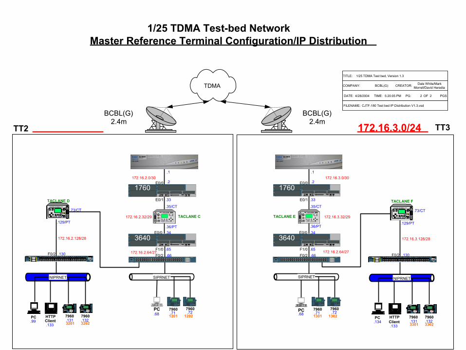
1/25 TDMA Test-bed NetworkMaster Reference Terminal Configuration/IP Distribution
FILENAME: CJTF-180 Test bed IP Distribution V1.3.vsd
5:20:05 PM 2DATE: TIME: PG: OF PGS24/28/2004
Dale White/MarkMorrell/David HerediaCOMPANY: CREATOR:BCBL(G)
TITLE: 1/25 TDMA Test bed, Version 1.3
1/25 TDMA Test-bed NetworkMaster Reference Terminal Configuration/IP Distribution
TDMA
BCBL(G)2.4m
BCBL(G)2.4m
TT2 TT3172.16.3.0/24
3600
3640
PC HTTPClient
7960 7960
3201.99.133
.131 .1323202
36403640
1 2
ABC
3
DEF
4 5
JKL
6
MNOGHI
7 8
TUV
9
WXYZPQRS
*0
OPER
#
7960
CISCO IP PHONE
imessages directories
settingsservices
1 2
ABC
3
DEF
4 5
JKL
6
MNOGHI
7 8
TUV
9
WXYZPQRS
*0
OPER
#
7960
CISCO IP PHONE
imessages directories
settingsservices
SIPRNET
AUX
ACT
LINK100 Mbps
ACT
LINK100 Mbps
FASTETHERNET 0/1FASTETHERNET 0/0 CONSOLE
W2 W1 W0
Cisco 3725CF1
2 3
SYST RPS
STRT DUPLXSPEEDUTIL
MODE
Catalyst 2950 SERIES3
4
5
6
7
8
9
10
1
2
11
12
13
14
15
16
19
20
21
22
23
24
25
26
17
18
27
28
29
30
31
32
35
36
37
38
39
40
41
42
33
34
43
44
45
46
47
48
2
1
79607960
ZEROIZE
TACLANE (KG-175)
ONOFF
CIK
FILL
POWERALARM
RUNBATTERY LOW
Battery
DisplayContrast
ZEROIZE
TACLANE (KG-175)
ONOFF
CIK
FILL
POWERALARM
RUNBATTERY LOW
Battery
DisplayContrast
TACLANE C172.16.2.32/29
.1
172.16.2.64/27.65.66
.71 .721201 1202
.34E0/0
F1/0
PC.68
F0/2
3640
.35/CT
.36/PT
172.16.2.0/30
AUX
ACT
LINK100 Mbps
ACT
LINK100 Mbps
FASTETHERNET 0/1FASTETHERNET 0/0 CONSOLE
W2 W1 W0
Cisco 3725CF1
2 31760E0/0 .2
E0/1 .33
NIPRNET
PC HTTPClient
7960 7960
3301.134.133
.131 .1323302
36403640
1 2
ABC
3
DEF
4 5
JKL
6
MNOGHI
7 8
TUV
9
WXYZPQRS
*0
OPER
#
7960
CISCO IP PHONE
imessages directories
settingsservices
1 2
ABC
3
DEF
4 5
JKL
6
MNOGHI
7 8
TUV
9
WXYZPQRS
*0
OPER
#
7960
CISCO IP PHONE
imessages directories
settingsservices
SIPRNET
AUX
ACT
LINK100 Mbps
ACT
LINK100 Mbps
FASTETHERNET 0/1FASTETHERNET 0/0 CONSOLE
W2 W1 W0
Cisco 3725CF1
2 3
SYST RPS
STRT DUPLXSPEEDUTIL
MODE
Catalyst 2950 SERIES3
4
5
6
7
8
9
10
1
2
11
12
13
14
15
16
19
20
21
22
23
24
25
26
17
18
27
28
29
30
31
32
35
36
37
38
39
40
41
42
33
34
43
44
45
46
47
48
2
1
79607960
ZEROIZE
TACLANE (KG-175)
ONOFF
CIK
FILL
POWERALARM
RUNBATTERY LOW
Battery
DisplayContrast
ZEROIZE
TACLANE (KG-175)
ONOFF
CIK
FILL
POWERALARM
RUNBATTERY LOW
Battery
DisplayContrast
TACLANE E 172.16.3.32/29
.1
172.16.2.64/27.65.66
.71 .721301 1302
.34E0/0
F1/0
PC.68
F0/2
3640
.35/CT
.36/PT
172.16.3.0/30
AUX
ACT
LINK100 Mbps
ACT
LINK100 Mbps
FASTETHERNET 0/1FASTETHERNET 0/0 CONSOLE
W2 W1 W0
Cisco 3725CF1
2 31760E0/0 .2
E0/1 .33
NIPRNET
TACLANE D
172.16.2.128/28
.130
.73/CT
.129/PT
F0/2
TACLANE F
172.16.3.128/28
.130
.73/CT
.129/PT
F0/2
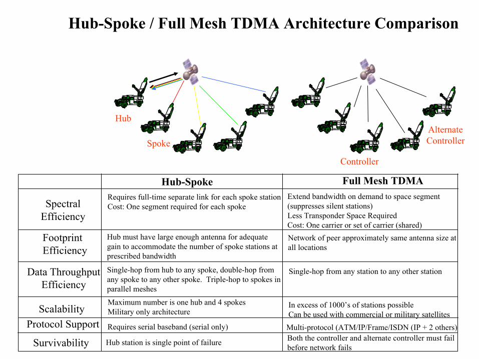
Hub-Spoke / Full Mesh TDMA Architecture Comparison
Full Mesh TDMAHub-Spoke
SpectralEfficiency
FootprintEfficiency
Data ThroughputEfficiency
Survivability
Requires full-time separate link for each spoke stationCost: One segment required for each spoke
Controller
AlternateController
Hub
Spoke
Hub must have large enough antenna for adequate gain to accommodate the number of spoke stations at prescribed bandwidth
Single-hop from hub to any spoke, double-hop fromany spoke to any other spoke. Triple-hop to spokes in parallel meshes
Single-hop from any station to any other station
Hub station is single point of failure Both the controller and alternate controller must failbefore network fails
Extend bandwidth on demand to space segment (suppresses silent stations)Less Transponder Space RequiredCost: One carrier or set of carrier (shared)Network of peer approximately same antenna size at all locations
ScalabilityMaximum number is one hub and 4 spokesMilitary only architecture
In excess of 1000’s of stations possibleCan be used with commercial or military satellites
Protocol Support Requires serial baseband (serial only) Multi-protocol (ATM/IP/Frame/ISDN (IP + 2 others)

Near Term Digital Radio (NTDR)
• Freq Range 225-450 MHz• Direct Sequence Spread Spectrum Modulation• 3 Channels to communicate
– Reservation – Cluster member Channel– Cluster head channel
• Digital Cellular like Network– No fixed or permanent designated base stations– Semi Autonomous network– Protocols Used( Receiver Directed Protocol & Multiple Access
Collision Avoidance Protocol • One Interface through an attached Cisco Router
SBCT Radio Transmission Methods
• SINCGARS-ASIP• EPLRS• NTDR• Harris HF Radio• SPITFIRE• SMART-T

SPITFIRE: AN/PSC-5
• Manpacked/Vehicle Mounted• Frequency Range: 30-400 MHz• Single Channel/Demand Assigned Multiple Access
(DAMA)• Interfaces w/ SINCGARS/ASIP Waveforms• Omni Directional Antennae

SMART-T• Secure Mobile Anti Jam Reliable Tactical Terminal• MILSTAR II Satellite• EHF: Range Extension for MSE• Data Rate:
– 4 separate data steams 128, 256, 512,1024– 1 data stream at a 1.544 Mbps: DS-1
• No terminals at the Battalion Level• Inter-TOC Communications (1024 Kbps)• CERTEX: 1 additional SMART-T; 3 additional AN/TSC-
93 SATCOM Terminals


![Satcom Overview[1]](https://img.dokumen.tips/doc/110x75/577d23ae1a28ab4e1e9a7a50/satcom-overview1.jpg)

