Embed Size (px)
Citation preview

© 2011 Microchip Technology Inc. Preliminary DS70671A
MCW1001A Data Sheet
TCP/IP Socket Communications Interface with GPIO

Note the following details of the code protection feature on Microchip devices:• Microchip products meet the specification contained in their particular Microchip Data Sheet.
• Microchip believes that its family of products is one of the most secure families of its kind on the market today, when used in the intended manner and under normal conditions.
• There are dishonest and possibly illegal methods used to breach the code protection feature. All of these methods, to our knowledge, require using the Microchip products in a manner outside the operating specifications contained in Microchip’s Data Sheets. Most likely, the person doing so is engaged in theft of intellectual property.
• Microchip is willing to work with the customer who is concerned about the integrity of their code.
• Neither Microchip nor any other semiconductor manufacturer can guarantee the security of their code. Code protection does not mean that we are guaranteeing the product as “unbreakable.”
Code protection is constantly evolving. We at Microchip are committed to continuously improving the code protection features of our products. Attempts to break Microchip’s code protection feature may be a violation of the Digital Millennium Copyright Act. If such acts allow unauthorized access to your software or other copyrighted work, you may have a right to sue for relief under that Act.
Information contained in this publication regarding device applications and the like is provided only for your convenience and may be superseded by updates. It is your responsibility to ensure that your application meets with your specifications. MICROCHIP MAKES NO REPRESENTATIONS OR WARRANTIES OF ANY KIND WHETHER EXPRESS OR IMPLIED, WRITTEN OR ORAL, STATUTORY OR OTHERWISE, RELATED TO THE INFORMATION, INCLUDING BUT NOT LIMITED TO ITS CONDITION, QUALITY, PERFORMANCE, MERCHANTABILITY OR FITNESS FOR PURPOSE. Microchip disclaims all liability arising from this information and its use. Use of Microchip devices in life support and/or safety applications is entirely at the buyer’s risk, and the buyer agrees to defend, indemnify and hold harmless Microchip from any and all damages, claims, suits, or expenses resulting from such use. No licenses are conveyed, implicitly or otherwise, under any Microchip intellectual property rights.
DS70671A-page 2 Prelimin
Trademarks
The Microchip name and logo, the Microchip logo, dsPIC, KEELOQ, KEELOQ logo, MPLAB, PIC, PICmicro, PICSTART, PIC32 logo, rfPIC and UNI/O are registered trademarks of Microchip Technology Incorporated in the U.S.A. and other countries.
FilterLab, Hampshire, HI-TECH C, Linear Active Thermistor, MXDEV, MXLAB, SEEVAL and The Embedded Control Solutions Company are registered trademarks of Microchip Technology Incorporated in the U.S.A.
Analog-for-the-Digital Age, Application Maestro, chipKIT, chipKIT logo, CodeGuard, dsPICDEM, dsPICDEM.net, dsPICworks, dsSPEAK, ECAN, ECONOMONITOR, FanSense, HI-TIDE, In-Circuit Serial Programming, ICSP, Mindi, MiWi, MPASM, MPLAB Certified logo, MPLIB, MPLINK, mTouch, Omniscient Code Generation, PICC, PICC-18, PICDEM, PICDEM.net, PICkit, PICtail, REAL ICE, rfLAB, Select Mode, Total Endurance, TSHARC, UniWinDriver, WiperLock and ZENA are trademarks of Microchip Technology Incorporated in the U.S.A. and other countries.
SQTP is a service mark of Microchip Technology Incorporated in the U.S.A.
All other trademarks mentioned herein are property of their respective companies.
© 2011, Microchip Technology Incorporated, Printed in the U.S.A., All Rights Reserved.
Printed on recycled paper.
ISBN: 978-1-61341-681-5
ary © 2011 Microchip Technology Inc.
Microchip received ISO/TS-16949:2009 certification for its worldwide headquarters, design and wafer fabrication facilities in Chandler and Tempe, Arizona; Gresham, Oregon and design centers in California and India. The Company’s quality system processes and procedures are for its PIC® MCUs and dsPIC® DSCs, KEELOQ® code hopping devices, Serial EEPROMs, microperipherals, nonvolatile memory and analog products. In addition, Microchip’s quality system for the design and manufacture of development systems is ISO 9001:2000 certified.

MCW1001ATCP/IP Socket Communications Interface with GPIO
Key Features:• Supports BSD like socket based connections • Built-in Wi-Fi® connection management
messages- Simplifies finding, connecting and
maintaining a Wi-Fi connection• Easy-to-use messaging interface • No external memory required• Connects through Universal Asynchronous
Receiver/Transmitter (UART)• Operates seamlessly with the MRF24WB0MA/MB
802.11 modules• Easy integration into a final product
- Accelerates product development, provides quicker time to market
• Designed for use with any microprocessor hosting a UART port
• 8 general-purpose digital I/O• Small size: 28 SSOP
Operational:• Single operating voltage: 2.7V–3.6V(3.3V typical) • Temperature range: -40°C to +85°C industrial • UART interface, up to 230 Kbaud • Low-current consumption:
- 10 mA operational current
Applications:• Using MRF24WB0M module with standard UART
interface• Using custom stacks with Microchip
microcontrollers
Markets:• Utility and Smart Energy
- Thermostats - Smart Meters- White Goods- HVAC
• Consumer Electronics- Home security
• Industrial Controls- Chemical sensors - HVAC - Security systems - M2M communication
• Remote Device Management - Automotive - Code update
• Retail - POS Terminals
• Medical, Fitness, and Health care - Glucose meters - Fitness equipment - Patient asset tracking
© 2011 Microchip Technology Inc. Preliminary DS70671A-page 3

MCW1001A
Pin Diagram1
10
9
8
7
6
5
4
3
2
23
24
25
26
27
28
14
13
12
11
19
20
21
22
16
17
18
15
RESET
VSS
VDD
WINT
OSC2
OSC1
VSS
NC
GPIO7
GPIO6
GPIO5
URTS
UCTS
WWPGPIO4
VCAP
GPIO3
GPIO2
GPIO1
GPIO0
WSD0
UTX
URX
WSCK
WHIB
WRST
WCS
WSDI
MCW1001A
SSOP
DS70671A-page 4 Preliminary © 2011 Microchip Technology Inc.

MCW1001A
Table of Contents1.0 Device Overview .......................................................................................................................................................................... 72.0 External Connections ................................................................................................................................................................. 153.0 Universal Asynchronous Receiver (UART) ................................................................................................................................ 194.0 Network Configuration................................................................................................................................................................ 215.0 Transmitting And Receiving Packets.......................................................................................................................................... 236.0 Messaging API ........................................................................................................................................................................... 257.0 Electrical Characteristics ............................................................................................................................................................ 518.0 Packaging Information................................................................................................................................................................ 57Appendix A: Revision history ............................................................................................................................................................... 61The Microchip Web Site....................................................................................................................................................................... 63Customer Change Notification Service ................................................................................................................................................ 63Customer Support ................................................................................................................................................................................ 63Reader Response ................................................................................................................................................................................ 64Product Identification System .............................................................................................................................................................. 65TO OUR VALUED CUSTOMERSIt is our intention to provide our valued customers with the best documentation possible to ensure successful use of your Microchip products. To this end, we will continue to improve our publications to better suit your needs. Our publications will be refined and enhanced as new volumes and updates are introduced. If you have any questions or comments regarding this publication, please contact the Marketing Communications Department via E-mail at [email protected] or fax the Reader Response Form in the back of this data sheet to (480) 792-4150. We welcome your feedback.
Most Current Data SheetTo obtain the most up-to-date version of this data sheet, please register at our Worldwide Web site at:
http://www.microchip.comYou can determine the version of a data sheet by examining its literature number found on the bottom outside corner of any page. The last character of the literature number is the version number, (e.g., DS30000A is version A of document DS30000).
ErrataAn errata sheet, describing minor operational differences from the data sheet and recommended workarounds, may exist for current devices. As device/documentation issues become known to us, we will publish an errata sheet. The errata will specify the revision of silicon and revision of document to which it applies.To determine if an errata sheet exists for a particular device, please check with one of the following:• Microchip’s Worldwide Web site; http://www.microchip.com• Your local Microchip sales office (see last page)When contacting a sales office, please specify which device, revision of silicon and data sheet (include literature number) you are using.
Customer Notification SystemRegister on our web site at www.microchip.com to receive the most current information on all of our products.
© 2011 Microchip Technology Inc. Preliminary DS70671A-page 5

MCW1001A
NOTES:DS70671A-page 6 Preliminary © 2011 Microchip Technology Inc.

MCW1001A
1.0 DEVICE OVERVIEWThe MCW1001A is a companion chip to the MRF24WB0 802.11 module. It provides simple socket based method of sending and receiving data from the MRF24WB0 802.11 module. The MCW1001A has an on-board TCP/IP stack and 802.11 connection manager to simplify the connection between a wireless network and the TCP/IP stack management. After the initial configuration is set, the MCW1001A can access the MRF24WB0 802.11 module to connect to a network and send/receive serial data over a simple UART interface.
Figure 1-1 illustrates a general block diagram of the MCW1001A device.
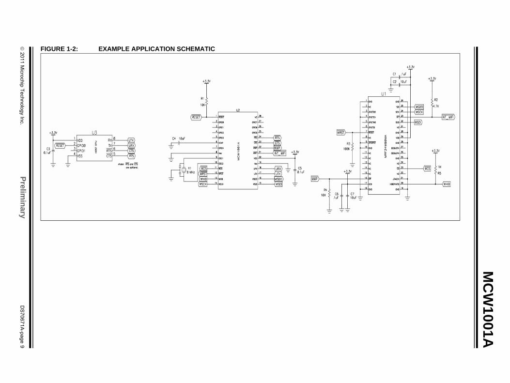
Figure 1-2 illustrates application schematic.
Figure 1-3 illustrates application block diagram.
Table 1-1 lists the functions of the various pins shown in the pin diagram.
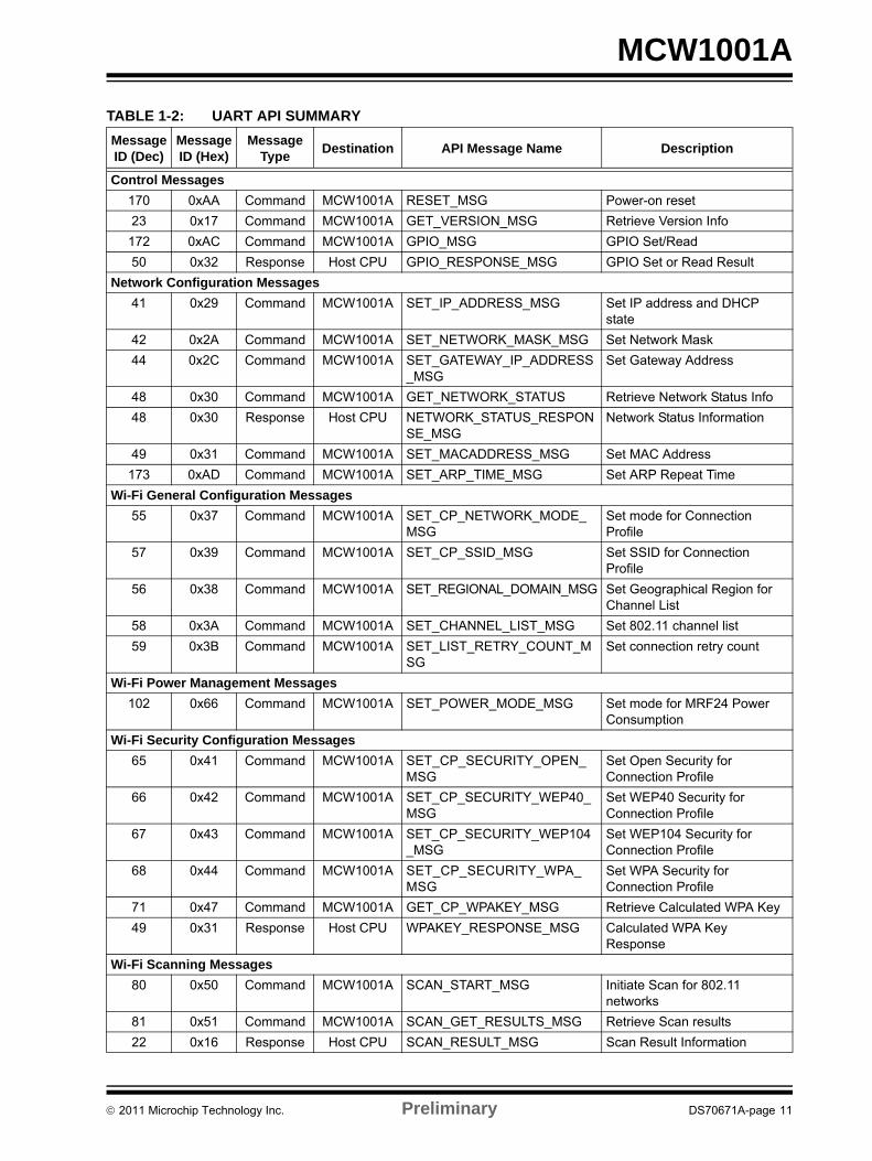
Table 1-2 lists the UART API summary
FIGURE 1-1: BLOCK DIAGRAM
UARTController
BaudGenerator
Control
Wi-Fi
TCP/IP Stack
MRF24WMB0Driver
VSS Reset Oscillator Voltage Regulator
GPIO1
UTX
URTS
URX
UCTS
GPI0 [0-7]
VSS VDDOSC2OSC1RESET
WWP
WCS
WSCK
WSDO
WSDI
WINT
WRST
WHIB
ManagerConnection
© 2011 Microchip Technology Inc. Preliminary DS70671A-page 7

MCW1001A
TABLE 1-1: PINOUT DESCRIPTIONPin Number Pin Name Type Description
1 RESET I Active-low Reset to the device.2 GPIO0 I/O General-purpose I/O3 GPIO1 I/O General-purpose I/O4 GPIO2 I/O General-purpose I/O5 GPIO3 I/O General-purpose I/O6 VCAP I External filter capacitor connection for internal regulator7 GPIO4 I/O General-purpose I/O8 VSS P Ground9 OSC1 I Oscillator input10 OSC2 O Oscillator output11 WCS O SPI Slave select output to MRF24WB0M12 WRST O External Reset output control to MRF24WB0M13 WHIB O HIBERNATE mode enable output to MRF24WB0M14 WSCK O SPI clock output to MRF24WB0M15 WSDI I SPI data input from MRF24WB0M16 WSDO O SPI data output to MRF24WB0M17 UTX O USART asynchronous transmit18 URX I USART asynchronous receive19 VSS P Ground20 VDD P Power21 WINT I External interrupt from MRF24WMB022 WWP O External write protect control to MRF24WB0M23 UCTS I USART asynchronous clear to send (optional)24 URTS O USART asynchronous request to send (optional)25 GPIO5 I/O General-purpose I/O26 GPIO6 I/O General-purpose I/O27 GPIO7 I/O General-purpose I/O28 NC NC No Connect
Legend: Pin type abbreviation: P = Power input I = Input O = Output NC = No Connect
Note: Signals of Type “I: Constant” must either be constantly driven by the host or have a pull-up or pull-down (in case the host is likely to tri-state the signal during power down modes). The constant drive is used to ensure defined operation of the part and to minimize leakage current during low-power operation.
DS70671A-page 8 Preliminary © 2011 Microchip Technology Inc.
© 2011 M
icrochip Technology Inc.Prelim
inaryD
S70671A
-page 9
MC
W1001A
F
IGURE 1-2: EXAMPLE APPLICATION SCHEMATIC
MCW1001A
FIGURE 1-3: APPLICATION BLOCK DIAGRAM© 2011 Microchip Technology Inc. Preliminary DS70671A-page 10
MCW1001A
TABLE 1-2: UART API SUMMARYMessage ID (Dec)
Message ID (Hex)
Message Type Destination API Message Name Description
Control Messages170 0xAA Command MCW1001A RESET_MSG Power-on reset23 0x17 Command MCW1001A GET_VERSION_MSG Retrieve Version Info172 0xAC Command MCW1001A GPIO_MSG GPIO Set/Read50 0x32 Response Host CPU GPIO_RESPONSE_MSG GPIO Set or Read Result
Network Configuration Messages41 0x29 Command MCW1001A SET_IP_ADDRESS_MSG Set IP address and DHCP
state42 0x2A Command MCW1001A SET_NETWORK_MASK_MSG Set Network Mask44 0x2C Command MCW1001A SET_GATEWAY_IP_ADDRESS
_MSGSet Gateway Address
48 0x30 Command MCW1001A GET_NETWORK_STATUS Retrieve Network Status Info48 0x30 Response Host CPU NETWORK_STATUS_RESPON
SE_MSGNetwork Status Information
49 0x31 Command MCW1001A SET_MACADDRESS_MSG Set MAC Address173 0xAD Command MCW1001A SET_ARP_TIME_MSG Set ARP Repeat Time
Wi-Fi General Configuration Messages55 0x37 Command MCW1001A SET_CP_NETWORK_MODE_
MSGSet mode for Connection Profile
57 0x39 Command MCW1001A SET_CP_SSID_MSG Set SSID for Connection Profile
56 0x38 Command MCW1001A SET_REGIONAL_DOMAIN_MSG Set Geographical Region for Channel List
58 0x3A Command MCW1001A SET_CHANNEL_LIST_MSG Set 802.11 channel list59 0x3B Command MCW1001A SET_LIST_RETRY_COUNT_M
SGSet connection retry count
Wi-Fi Power Management Messages102 0x66 Command MCW1001A SET_POWER_MODE_MSG Set mode for MRF24 Power
ConsumptionWi-Fi Security Configuration Messages
65 0x41 Command MCW1001A SET_CP_SECURITY_OPEN_MSG
Set Open Security for Connection Profile
66 0x42 Command MCW1001A SET_CP_SECURITY_WEP40_MSG
Set WEP40 Security for Connection Profile
67 0x43 Command MCW1001A SET_CP_SECURITY_WEP104_MSG
Set WEP104 Security for Connection Profile
68 0x44 Command MCW1001A SET_CP_SECURITY_WPA_MSG
Set WPA Security for Connection Profile
71 0x47 Command MCW1001A GET_CP_WPAKEY_MSG Retrieve Calculated WPA Key49 0x31 Response Host CPU WPAKEY_RESPONSE_MSG Calculated WPA Key
ResponseWi-Fi Scanning Messages
80 0x50 Command MCW1001A SCAN_START_MSG Initiate Scan for 802.11 networks
81 0x51 Command MCW1001A SCAN_GET_RESULTS_MSG Retrieve Scan results22 0x16 Response Host CPU SCAN_RESULT_MSG Scan Result Information
© 2011 Microchip Technology Inc. Preliminary DS70671A-page 11

MCW1001A
Wi-Fi Connection Messages90 0x5A Command MCW1001A WIFI_CONNECT_MSG Connect to specified
Connection Profile network91 0x5B Command MCW1001A WIFI_DISCONNECT_MSG Disconnect from 802.11
networkICMP (Ping) Messages
121 0x79 Command MCW1001A PING_SEND_MSG Send Ping to ICMP HostSocket Messages
110 0x6E Command MCW1001A SOCKET_CREATE_MSG Create BSD Socket for TCP or UDP
23 0x17 Response Host CPU SOCKET_CREATE_RESPONSE_MSG
Socket Creation result
111 0x6F Command MCW1001A SOCKET_CLOSE_MSG Close BSD Socket112 0x70 Command MCW1001A SOCKET_BIND_MSG Bind Socket Handle to
specified port24 0x18 Response Host CPU SOCKET_BIND_RESPONSE_
MSGBind result
113 0x71 Command MCW1001A SOCKET_CONNECT_MSG Connect to remote BSD socket25 0x19 Response Host CPU SOCKET_CONNECT_RESPON
SE_MSGConnection result
114 0x72 Command MCW1001A SOCKET_LISTEN_MSG Create child sockets to listen for clients
26 0x1A Response Host CPU SOCKET_LISTEN_RESPONSE_MSG
Listen result
115 0x73 Command MCW1001A SOCKET_ACCEPT_MSG Accept client request for socket connection
27 0x1B Response Host CPU SOCKET_ACCEPT_RESPONSE_MSG
Accept result
116 0x74 Command MCW1001A SOCKET_SEND_MSG Send Data using specified socket
28 0x1C Response Host CPU SOCKET_SEND_RESPONSE_MSG
Send result
117 0x75 Command MCW1001A SOCKET_RECV_MSG Receive Data from specified socket
29 0x1D Response Host CPU SOCKET_RECV_RESPONSE_MSG
Receive result
118 0x76 Command MCW1001A SOCKET_SEND_TO_MSG Send Data using specified socket and destination
30 0x1E Response Host CPU SOCKET_SEND_TO_RESPONSE_MSG
Send To result
119 0x77 Command MCW1001A SOCKET_RECV_FROM_MSG Receive Data from specified socket and origin
31 0x1F Response Host CPU SOCKET_RECV_FROM_RESPONSE_MSG
Receive From result
122 0x7A Command MCW1001A SOCKET_ALLOCATE_MSG Allocate Socket Buffers32 0x20 Response Host CPU SOCKET_ALLOCATE_RESPO
NSE_MSGSocket Allocation result
TABLE 1-2: UART API SUMMARYMessage ID (Dec)
Message ID (Hex)
Message Type Destination API Message Name Description
DS70671A-page 12 Preliminary © 2011 Microchip Technology Inc.

MCW1001A
Asynchronous Event Messages Sent From MCW1001A to Host
1 0x1 Event 16 Host CPU EVENT_MSG – IP Address Assigned
New IP address assigned indication
1 0x1 Event 8 Host CPU EVENT_MSG – Wi-Fi Connection Status Changed
Connection Status changed indication
1 0x1 Event 9 Host CPU EVENT_MSG – Wi-Fi Scan Results Ready
Scan complete indication
1 0x1 Event 26 Host CPU EVENT_MSG – Ping Response Event
Ping response from ICMP server result indication
1 0x1 Event 255 Host CPU EVENT_MSG – Error Event Error indication containing error information
1 0x1 Event 27 Host CPU EVENT_MSG – Startup Event Version Information and Reset Reason
TABLE 1-2: UART API SUMMARYMessage ID (Dec)
Message ID (Hex)
Message Type Destination API Message Name Description
© 2011 Microchip Technology Inc. Preliminary DS70671A-page 13

MCW1001A
NOTES:DS70671A-page 14 Preliminary © 2011 Microchip Technology Inc.
MCW1001A
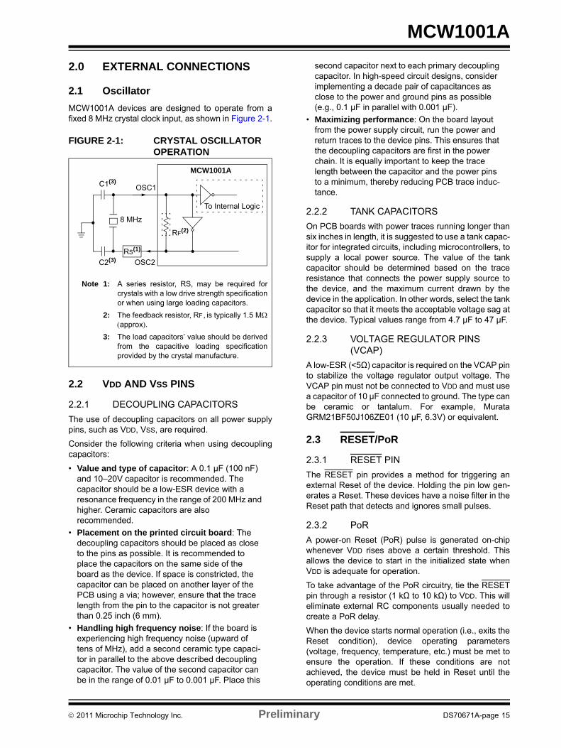
2.0 EXTERNAL CONNECTIONS2.1 OscillatorMCW1001A devices are designed to operate from a fixed 8 MHz crystal clock input, as shown in Figure 2-1.
FIGURE 2-1: CRYSTAL OSCILLATOR OPERATION
2.2 VDD AND VSS PINS
2.2.1 DECOUPLING CAPACITORSThe use of decoupling capacitors on all power supply pins, such as VDD, VSS, are required.
Consider the following criteria when using decoupling capacitors:
• Value and type of capacitor: A 0.1 μF (100 nF) and 10–20V capacitor is recommended. The capacitor should be a low-ESR device with a resonance frequency in the range of 200 MHz and higher. Ceramic capacitors are also recommended.
• Placement on the printed circuit board: The decoupling capacitors should be placed as close to the pins as possible. It is recommended to place the capacitors on the same side of the board as the device. If space is constricted, the capacitor can be placed on another layer of the PCB using a via; however, ensure that the trace length from the pin to the capacitor is not greater than 0.25 inch (6 mm).
• Handling high frequency noise: If the board is experiencing high frequency noise (upward of tens of MHz), add a second ceramic type capaci-tor in parallel to the above described decoupling capacitor. The value of the second capacitor can be in the range of 0.01 μF to 0.001 μF. Place this
second capacitor next to each primary decoupling capacitor. In high-speed circuit designs, consider implementing a decade pair of capacitances as close to the power and ground pins as possible (e.g., 0.1 μF in parallel with 0.001 μF).
• Maximizing performance: On the board layout from the power supply circuit, run the power and return traces to the device pins. This ensures that the decoupling capacitors are first in the power chain. It is equally important to keep the trace length between the capacitor and the power pins to a minimum, thereby reducing PCB trace induc-tance.
2.2.2 TANK CAPACITORSOn PCB boards with power traces running longer than six inches in length, it is suggested to use a tank capac-itor for integrated circuits, including microcontrollers, to supply a local power source. The value of the tank capacitor should be determined based on the trace resistance that connects the power supply source to the device, and the maximum current drawn by the device in the application. In other words, select the tank capacitor so that it meets the acceptable voltage sag at the device. Typical values range from 4.7 μF to 47 μF.
2.2.3 VOLTAGE REGULATOR PINS (VCAP)
A low-ESR (<5Ω) capacitor is required on the VCAP pin to stabilize the voltage regulator output voltage. The VCAP pin must not be connected to VDD and must use a capacitor of 10 μF connected to ground. The type can be ceramic or tantalum. For example, Murata GRM21BF50J106ZE01 (10 μF, 6.3V) or equivalent.
2.3 RESET/PoR
2.3.1 RESET PINThe RESET pin provides a method for triggering an external Reset of the device. Holding the pin low gen-erates a Reset. These devices have a noise filter in the Reset path that detects and ignores small pulses.
2.3.2 PoRA power-on Reset (PoR) pulse is generated on-chip whenever VDD rises above a certain threshold. This allows the device to start in the initialized state when VDD is adequate for operation.
To take advantage of the PoR circuitry, tie the RESETpin through a resistor (1 kΩ to 10 kΩ) to VDD. This will eliminate external RC components usually needed to create a PoR delay.
When the device starts normal operation (i.e., exits the Reset condition), device operating parameters (voltage, frequency, temperature, etc.) must be met to ensure the operation. If these conditions are not achieved, the device must be held in Reset until the operating conditions are met.
C1(3)
C2(3)
8 MHz
OSC2RS(1)
OSC1
RF(2)
To Internal Logic
Note 1: A series resistor, RS, may be required for crystals with a low drive strength specification or when using large loading capacitors.
2: The feedback resistor, RF, is typically 1.5 MΩ (approx).
3: The load capacitors’ value should be derived from the capacitive loading specification provided by the crystal manufacture.
MCW1001A
© 2011 Microchip Technology Inc. Preliminary DS70671A-page 15
MCW1001A
2.4 MCW1001A to MRF24WB0 802.11Module Interface
2.4.1 WSPI PINSThe MCW1001A Serial Peripheral Interface (WSPI) is used to communicate with the MRF24WB0 transceiver module.
2.4.2 WINT PINThe WSPI interface works with the Interrupt line (WINT) and must be pulled “High” through 4.7 kΩ resistor to VDD. When data is available for the MCW1001A during operation, the WINT line will be asserted (logic low) by the MRF24WB0 module. After the data is transferred to the MCW1001A, the WINTline will then be de-asserted (logic high) by the MRF24WB0 module.
2.4.3 WCS PINThe WCS pin must be connected to the CS pin of the MRF24WB0 and cannot be held low permanently. The falling edge of WCS is used to indicate the start of a transfer. The rising edge of WCS is used to indicate the completion of a single transfer.
2.4.4 WHIB PINThe WHIB pin is used to control the HIBERNATE feature of the MRF24WB0 and must be pulled “High” via 1 MΩ resistor to VDD. When WHIB is driven high, it puts the MRF24WB0M into Hibernate mode. The module contains about 70 uF of internal bulk capacitance so the system power supply should be provisioned to supply sufficient charge on release of hibernate to ensure proper startup. For more information on controlling the low-power modes of the MCW1001A, refer to Section 6.0, Messaging API.
2.4.5 WRST PINThe WRST pin is used to control RESET to the MRF24WB0.
DS70671A-page 16 Preliminary © 2011 Microchip Technology Inc.

MCW1001A
2.5 GPIO PINSWhen developing an application, the capabilities of the port pins must be considered. Outputs on some pins have higher output drive strength than others. Similarly, some pins can tolerate higher than VDD input levels.2.5.1 INPUT PINS AND VOLTAGE CONSIDERATIONS
The voltage tolerance of the GPIO pins varies across the bank of pins. Some of the pins when used as digital only inputs can handle DC voltages up to 5.5V, a level typical for digital logic circuits. Table summarizes the input voltage capabilities of the I/O pins. For more infor-mation on electrical characteristic, refer to Section 7.0, Electrical Characteristics. Voltage excursions beyond VDD on these pins should be avoided.
TABLE 2-1: INPUT VOLTAGE LEVELS
2.5.2 PIN OUTPUT DRIVEThe GPIO output pin drive strength varies across the GPIO bank of pins to meet the needs of a variety of applications. There are two classes of output pins in terms of drive capability.
• GPIO<5:7> – Designed to drive higher current loads, such as LED's.
• GPIO<0:4> – Designed for small loads, typically indication only. Table 2-2 summarizes the output capabilities. For more information, refer to the Section 7.0, Electrical Characteristics.
TABLE 2-2: OUTPUT DRIVE LEVELS
:
2.5.3 INTERFACING TO A +5V SYSTEMThough the VDDMAX of the MCW1001A is 3.6V, this device is still capable of interfacing with 5V systems, even if the VIH of the target system is above 3.6V. This is accomplished by adding a pull-up resistor to the GPIO pin, see Figure 2-2. To produce a high output, the GPIO pin must be configured as an input, and to produce a low output, the GPIO pin must be configured as an output and set low. Only GPIO pins that are tolerant of voltages up to 5.5V can be used for this type of interface.
FIGURE 2-2: +5V SYSTEM HARDWARE INTERFACE
Pin Tolerated Input Description
GPIO<0:4> VDD Only VDD input levels are tolerated.
GPIO<5:7> 5.5V Tolerates input levels above VDD and useful for most standard logic.
Pin Drive Description
GPIO<0:4> Medium Intended for indication.GPIO<5:7> High Suitable for direct LED drive
levels.
GPIO1
+5V Device+5VMCW1001A
© 2011 Microchip Technology Inc. Preliminary DS70671A-page 17

MCW1001A
NOTES:DS70671A-page 18 Preliminary © 2011 Microchip Technology Inc.

MCW1001A
3.0 UNIVERSAL ASYNCHRONOUS RECEIVER (UART)
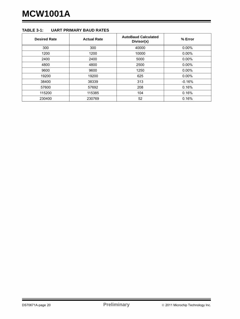
The MCW1001A UART interface consists of the UTX and URX data signals and the URTS/UCTS flow control pins. The UART is configurable for several baud rates. The available data formats and baud rates are listed in Table 3-1.
3.1 Initial ConfigurationFrom Reset, the UART is configured for 115200 baud, 8 bits, no parity, and 2 stop bits. The receiver does not require 2 stop bits, but the MCW1001A will always transmit serial data with 2 stop bits. It is recommended that the host use 2 stop bits to improve synchronization with long packets.
3.2 Autobaud RateThe autobaud feature of the MCW1001A requires that the initial byte sent from the host be 0x55. From Reset, autobaud is enabled, and the first byte sent will set the rate. This typically requires no special consideration as the first character of every well-formed packet contains 0x55. Because the receipt of this character cannot be guaranteed, there are two means of resetting back to the initialization point. The first is an active Reset (pull URTS low and return high), and the second is an auto-retry. If a valid fully-formed message is not received (indicating a synchronized baud rate) within 1s after the first byte that set the baud rate, WiComm-Socket will reinitialize the autobaud procedure and wait for the next 0x55 input to set the baud rate.
3.3 Rounding ErrorsThe primary baud rate setting (with the rounding errors) is shown in Table 3-1. If baud rates other than the ones shown in the table are used, the error percentage can be calculated using Equation 3-1 to find the actual baud rate.
3.4 Hardware Flow ControlHardware flow control uses the URTS and UCTS pins as a handshake between two devices. The URTS pin of one device is typically connected to the UCTS of the other device.
URTS is an active-low output that notifies the other device when it is ready to receive data by driving the pin low. The MCW1001A trip point for de-asserting URTS(high) is 499 characters. This is one character short of “buffer full”.
UCTS is an active-low input that notifies the MCW1001A when it is ready to send data. The MCW1001A will check UCTS just before loading and sending UART data. If the pin is asserted during a transfer, the transfer will continue as shown inFigure 3-1.
3.5 Flow Control DisabledHardware handshaking may be circumvented by physically tying the UCTS input low (active) instead of allowing it to be driven by the URTS signal from the host. In this case, the URTS output should be left unconnected, and allowed to freely change state.
FIGURE 3-1: URTS/UCTS CONNECTIONS EXAMPLE
EQUATION 3-1: SOLVING FOR ACTUAL BAUD RATE
URTS URTS
UCTS UCTS
I am ready to receive
I’ll transmit if okay
I am ready to receive
I’ll transmit if okay
MCU MCW1001A
ActualRate 12MHzint x( )
------------------=
Where:x 12MHz
DesiredBaud-----------------------------------=
© 2011 Microchip Technology Inc. Preliminary DS70671A-page 19
MCW1001A
TABLE 3-1: UART PRIMARY BAUD RATESDesired Rate Actual Rate AutoBaud Calculated Divisor(x) % Error
300 300 40000 0.00%1200 1200 10000 0.00%2400 2400 5000 0.00%4800 4800 2500 0.00%9600 9600 1250 0.00%
19200 19200 625 0.00%38400 38339 313 -0.16%57600 57692 208 0.16%115200 115385 104 0.16%230400 230769 52 0.16%
DS70671A-page 20 Preliminary © 2011 Microchip Technology Inc.

MCW1001A
4.0 NETWORK CONFIGURATIONConfiguring the MCW1001A to make a connection at a minimum requires setting the network type, choosing the network name and setting up the security parameters. It is possible to store connection information for two different Connection Profiles (CP) in the MCW1001A. After this information is provided, the network connection process can be initiated by referencing only the profile number (1 or 2).
4.1 Configuring 802.11 LinkThere are two types of networks. The most common network is infrastructure in which an access point (AP) is the common point linking all 802.11 devices. The access point keeps track of who's on the local network and directs IP packets. In many cases, the AP is also a router and will forward packets from the local network to other networks and to the Internet. It is also common for the AP to be running a DHCP server which tracks and assigns IP addresses. The second type is ad hoc, which is considered a point-to-point network in that each 802.11 device is linked directly to every other 802.11 device on the ad hoc network. There is no access point. All 802.11 devices on the ad hoc network participate in keeping the network alive and each keeps track of the other active devices on the network by sending and receiving beacon and probe packets. In most cases, IP addresses are assigned through Auto IP, although one of the 802.11 devices can be configured as a DHCP server. By default, the MCW1001A will operate as a DHCP server for one ad hoc client that may join a network created by the MCW1001A, but the IP address of the MCW1001A can be set to a static value through the API. The MCW1001A handles connection management internally under the direction of the host. The following example illustrates a typical connection process:
EXAMPLE 4-1: CREATING AN 802.11 LINK
The following is the procedure to create an 802.11 link:
1. Power up system and de-assert the RESETsignal to the MCW1001A.
2. Host will receive an asynchronous Reset message from MCW1001A using the default UART configuration.
3. Host sets desired network configuration through the API (may include scanning for the available network connections and choosing based on the scan results).
4. Host Issues Connect command.5. The MCW1001A then handles connection to the
network and sends asynchronous Event mes-sage when connection status changes.
4.2 Verifying the Network LinkTo verify a network link is established, the MCW1001A can operate as an ICMP host and/or client. To test the operation as a host, issue a Ping from another device on the network to the IP address obtained or set for the MCW1001A. The MCW1001A will respond to the Ping if the network is functional. To test the operation as a client, use the MCW1001A API to issue a Ping to a device on the network that has been previously verified to operate as an ICMP server. In both cases, verify that the IP subnet mask and gateway are configured through the MCW1001A API.
4.3 Network Stack ConfigurationThe MCW1001A has limited resources in terms of RAM available to buffer socket data and maintain information about socket connections. Support exists for TCP and UDP sockets, but a maximum of 8 instances of each are allowed.
UDP data is not buffered by MCW1001A. When the host MCU initiates an API UDP Send, the data sent over the serial port is immediately sent to the network. Similarly, whenever the MCW1001A receives UDP socket data from the network, that data is passed asynchronously to the host if the host has issued a RecvFrom or RECV Socket command for the socket receiving the data. By limiting the UDP socket instances to 8, the RAM required to maintain information about the UDP sockets is limited.
TCP data must be buffered by MCW1001A in both the directions. A TCP socket may be either a Server (responds to remote client requests) or a Client (requests data from remote Servers). 8192 bytes of RAM have been allocated for TCP socket data buffers. As it is impractical to decide in advance what the allocation of this RAM in terms of how many sockets are available or how large the buffers for the sockets are. The MCW1001A uses a socket allocation technique that allows the available RAM to be configured by the host prior to the creating of sockets. By default, 8 TCP sockets exist, each with a 512 byte transmit and receive buffer. Two sockets are client sockets, and remaining six are server sockets. The number of TCP sockets can be reduced to less than or equal to 8, and the amount of RAM for the send and receive buffers can be adjusted for the client and server socket types allowing the 8192 bytes to be allocated to TCP sockets in as large as 1500 byte blocks. All server sockets must be the same size, and all client sockets must be the same size.
Note: An asynchronous event will be sent to the host if the status of the connection maintained by MCW1001A changes.
© 2011 Microchip Technology Inc. Preliminary DS70671A-page 21

MCW1001A
NOTES:DS70671A-page 22 Preliminary © 2011 Microchip Technology Inc.

MCW1001A
5.0 TRANSMITTING AND RECEIVING PACKETS
5.1 TCPTCP is a standard transport layer protocol described in Request for Comments (RFC) 793. It provides reliable stream-based connections over unreliable networks, and forms the foundation for HTTP, SMTP, and many other protocol standards. Connections made over TCP guarantee data transfer at the expense of throughput. Connections are made through a three-way handshake process, ensuring a one-to-one connection. Remote nodes advertise how much data they are ready to receive, and all data transmitted must be acknowledged. If a remote node fails to acknowledge the receipt of data, it is automatically retransmitted. This ensures that network errors such as lost, corrupted, or out-of-order packets are automatically corrected. To accomplish this, TCP must operate in a buffer. Once the transmit buffer is full, no more data can be sent until the remote node has acknowledged receipt. Likewise, the remote node cannot transmit more data until the local device has acknowledged receipt and that space is available in the buffer. The following example illustrates how to use TCP packets:
EXAMPLE 5-1: USING TCP PACKETS
The MCW1001A TCP sockets can be configured as servers or clients. The procedure for transferring TCP packet data in each configuration differs slightly.
5.1.1 MCW1001A TCP SERVER EXAMPLE:
1. Create a TCP socket with call to socket(). This will return an 8-bit socket handle to be used when later referencing this socket.
2. Bind the socket to the listen port with call to bind(). The bind API specifies the 16-bit local port number that the client will attempt a connection on.
3. Prepare the socket to listen for a connection with call to listen(). The listen process opens the specified number of listening sockets that become the children sockets of the bound parent. They will all listen to the port specified in the bind process, but they may accept connections from different clients (different IP addresses, different remote port numbers). If the number of sockets specified is not available, the listen process will return the number of sockets it was not able to allocate.
4. Accept incoming connection through a call to accept(). Accept is non-blocking for the MCW1001A and accepting a connection from a client must be done through polling the socket with the Accept API.
5. Communicate with the remote host using send() and recv().
6. Close the socket with call to close().
5.1.2 MCW1001A TCP CLIENT EXAMPLE:1. Create a TCP socket with call to socket().2. Optionally apply a local port number with a call
to bind(). Otherwise, a pseudo-random local port number will be assigned.
3. Connect to the server with call to connect(), passing sockaddr, IP address.
4. Communicate with the remote host using send() and recv().
5. Close the socket with call to close().
© 2011 Microchip Technology Inc. Preliminary DS70671A-page 23

MCW1001A
5.2 UDPUDP is a standard transport layer protocol described in Request for Comments (RFC) 768. It provides fast but unreliable data-gram based transfers over networks, and forms the foundation SNTP, SNMP, DNS, and many other protocol standards. Connections over UDP should be thought of as data-gram based transfers. Each packet is a separate entity, the application should expect some packets to arrive out-of-order or even fail to reach the destination node. This is in contrast to TCP, in which the connection is thought of as a stream and network errors are automatically corrected. These tradeoffs in reliability are made for an increase in throughput. In general, UDP transfers operate two to three times faster than those made over TCP. As UDP is packet-oriented, each packet must be dealt with in its entirety by your application before returning to the main stack loop. When a packet is received, your application will be called to handle it. This packet will no longer be available the next time your application is called. Therefor, you must either perform all necessary processing or copy the data elsewhere before returning. When transmitting a packet, your application must build and transmit the complete packet in one cycle. The following example illustrates how to use the TCP packets.EXAMPLE 5-2: USING UDP PACKETS
The MCW1001A UDP sockets require less configuration than the TCP counterparts. Sending packets using UDP sockets can be accomplished by creating the socket and issuing a Sendto() command specifying the destination address and port number. Receiving packets on a UDP socket requires an extra bind step to set the local port number.
5.2.1 MCW1001A UDP SERVER EXAMPLE:
1. Create a UDP socket with a call to socket specifying the UDP socket type. If successful, an 8-bit socket handle will be returned.
2. Bind the socket to a local port number with a call to bind()
3. Receive data using this socket with a call to recvfrom()
4. Optionally reply to the client with a call to Sendto() specifying the returned address and port number returned in the recvfrom() call.
5.2.2 MCW1001A UDP CLIENT EXAMPLE:
1. Create the UDP socket with a call to socket specifying the UDP socket type. If successful, an 8 bit socket handle will be returned.
2. Transmit data to a remote UDP server with a call to Sendto() specifying the remote IP address and port number.
3. Optionally receive data from the server using this socket with a call to recvfrom().
DS70671A-page 24 Preliminary © 2011 Microchip Technology Inc.

MCW1001A
6.0 MESSAGING APIThe API between the host processor and the MCW1001A can be divided into two logical groups of commands. The first set of commands deal with 802.11 connection management, while the second set deals with the BSD Socket Interface. In addition to commands sent from the host to the MCW1001A, several asynchronous messages can be transmitted directly from the MCW1001A to the host like:
• IP address assigned• 802.11 connection status changed• 802.11 scan results ready• Ping response event• Error Event (including Reset condition)
The size of the transmit and receive buffers for the serial API are limited for MCW1001A. While, it is possible for the host to receive a message from the MCW1001A as large as 1536 bytes, it is possible only to transmit messages to the MCW1001A in 500 byte packets.
6.1 OverviewThe WiComm-Socket Serial interface supports UART communication with a host system using no parity, 8 data bits, and 2 stop bits (N,8,2). By default, the baud rate is 115200 BPS, but autobaud may be used to adjust this rate. The rate at which the host sends the first character to WiComm-Socket (0x55) determines the data rate. The allowed values are between 300 baud and 230400 baud.
6.2 WiComm-Socket Packet FormatFigure 6-1 shows the packet format for all serial messages exchanged between the host and WiComm-Socket.
FIGURE 6-1: HOST CPU PACKET FORMAT
• Header0 – Always 0x55• Header1– Always 0xAA• MsgType – 16-bit field containing the message type• Msg Data Length – 16-bit field containing the number of data bytes that follow (can be 0)• Msg Data – Message data bytes• Trailer – Always one byte equal to 0x45
From the perspective of the host, WiComm-Socket has a little-endian interface. All 16 and 32-bit message fields are represented in an little-endian format.
Where an IP address is specified, 16 bytes are allocated for future compatibility with IPv6. However, for the current implementation of WiComm-Socket, IPv4 is used exclusively, and the first (left most) 4 bytes of the 16 byte field refer to the IPv4 address.
Header0(1)
Header1(1)
Msg Type(2)
Msg Data Length(2)
Msg Data(0 thru N)
Trailer(1)
© 2011 Microchip Technology Inc. Preliminary DS70671A-page 25

MCW1001A
6.3 WiComm-Socket Control MessagesMessages described in this section are used to manage Wicomm-Socket in areas unrelated to wireless networking.6.3.1 RESET_MSG (170 COMMAND)WiComm-Socket can be reset to the initialization vector by issuing the RESET_MSG. Becasue there is no internal non-volatile memory, all configuration parameters will be reset to default values. A single ACK_MSG will confirm receipt of this command prior to the reset. Upon a successful reset, WiComm-Socket will issue an EVENT_MSG - Startup Event.
Response Message: ACK_MSG
6.3.2 GET_VERSION_MSG (23 COMMAND)In response to this command, Wicomm-Socket will issue the EVENT-MSG – Startup Event which contains version infor-mation.
Response Message: ACK_MSG followed by asynchronous EVENT_MSG – Startup Event
6.3.3 GPIO_MSG (172 COMMAND)WiComm-Socket can be directed to write/read to/from GPIO pins by the host. Refer to the component diagram for GPIO index numbers that correspond to particular package pins. Using this index, the host may use this command to force the I/O pin to source current as an output in either a high or low logic state, or the host may read the pin state by using “Read Input” as the GPIO operation. A GPIO response will be issued to allow WiComm-Socket to report the current state of the selected pin.
Response Message: GPIO_RESPONSE_MSG
6.3.4 GPIO_RESPONSE_MSG (50 RESPONSE)In response to a GPIO_MSG, WiComm-Socket will return the current state of the particular I/O pin. This message con-tains the index of the pin that has been operated on, and the result of the operation.
Response Message: GPIO_RESPONSE_MSG
Msg Byte Index Description
0:5 Header; Message Type = 170, Data Length = 06 0x45 (Frame Trailer)
Msg Byte Index Description
0:5 Header; Message Type = 23, Data Length = 06 0x45 (Frame Trailer)
Msg Byte Index Description
0:5 Header; Message Type = 172, Data Length = 26 GPIO Index7 GPIO Operation - 0 = Set Output Low, 1 = Set Output High, 2 = Read Input8 0x45 (Frame Trailer)
Msg Byte Index Description
0:5 Header; Message Type = 50, Data Length = 26 GPIO Index7 GPIO Result – 0 = Output Low
1 = Output High 2 = Input Low 3 = Input High 255 = Invalid Index
8 0x45 (Frame Trailer)
DS70671A-page 26 Preliminary © 2011 Microchip Technology Inc.

MCW1001A
6.4 Network Configuration MessagesThe Network configuration messages are used to configure the basic network settings.The default network configuration messages are:
• Use DHCP to assign IP address• DHCP name 'W' + last 6 digits of MAC address • No Gateway IP address needed• No DNS IP address needed• Netmask = 255.255.255.0
The messages described in this section are used to change the default network configuration.
6.4.1 SET_IP_ADDRESS_MSG (41 COMMAND)By default WiComm-Socket uses DHCP to get an IP address. This message can configure WiComm-Socket to use a static IP address or switch back to using DHCP. WiComm-Socket always responds to this message with an ACK_MSG. In addition, if using DHCP, an EVENT_MSG containing the IP address will be sent to the host CPU asynchronously when WiComm- Socket is assigned an IP address by an AP.
Response Message: ACK_MSG
6.4.2 SET_NETWORK_MASK_MSG (42 COMMAND)By default WiComm-Socket will use a network mask of 255.255.255.0 to set the network mask configuration.
Response Message: ACK_MSG
6.4.3 SET_GATEWAY_IP_ADDRESS_MSG (44COMMAND)By default WiComm-Socket has a Gateway IP address of 0.0.0.0 (signifying that there is no Gateway) to set the network mass configuration.
Response Message: ACK_MSG
Msg Byte Index Description
0:5 Header; Message Type = 41, Data Length = 186 Reserved7 Static IP address flag:
• 0 – Use DHCP to assign IP address (default)• 1 – Use static IP addressIf using static IP address then set the next data field to the static IP address. Otherwise, set the IP address bytes to 0.
8:23 Static IP address 24 0x45 (Frame Trailer)
Msg Byte Index Description
0:5 Header; Message Type = 42, Data Length = 166:21 Network Mask (e.g. 255.255.0.0)22 0x45 (Frame Trailer)
Msg Byte Index Description
0:5 Header; Message Type = 44, Data Length = 166:21 Gateway IP address. If the Gateway IP address is set to 0.0.0.0 then WiComm-Socket will not
use a gateway.22 0x45 (Frame Trailer)
© 2011 Microchip Technology Inc. Preliminary DS70671A-page 27

MCW1001A
6.4.4 GET_NETWORK_STATUS (48 COMMAND)This function queries WiComm-Socket for the current network status (see network status response msg).Response Message: Network_Status_Response_Msg
6.4.5 NETWORK_STATUS_RESPONSE_MSG (48 RESPONSE)This message sent by WiComm-Socket describes the specified network interface configuration and whether it is currently connected.
6.4.6 SET_MACADDRESS_MSG (49 COMMAND)Specifies the MAC Address. This command should only be used at initialization.
Response Message: ACK_MSG
6.4.7 SET_ARP_TIME_MSG (173 COMMAND)This message allows the automatic or gratuitous ARP timing to be customized. By default, when connected, WiComm-Socket will issue an ARP at 5 second intervals. By using this API, the ARP period can be adjusted up to 65535 seconds. A special case of 0 turns off the automatic ARP function.
Response Message: ACK_MSG
Msg Byte Index Description
0:5 Header; Message Type = 48, Data Length = 06 0x45 (Frame Trailer)
Msg Byte Index Description
0:5 Header; Message Type = 48, Data Length = 566 Reserved
7:12 MAC Address (6 bytes)13:28 IP Address (16 bytes)29:44 Network Mask (16 bytes)45:60 Gateway Address (16 bytes)
61 Network Status – 0 = Not Connected Static IP 1 = Connected Static IP 2 = Not Connected DHCP 3 = Connected DHCP
62 0x45 (Frame Trailer)
Msg Byte Index Description
0:5 Header; Message Type = 48, Data Length = 66:11 MAC Address (6 bytes)12 0x45 (Frame Trailer)
Msg Byte Index Description
0:5 Header; Message Type = 173, Data Length = 26:7 ARP period in seconds8 0x45 (frame trailer)
DS70671A-page 28 Preliminary © 2011 Microchip Technology Inc.

MCW1001A
6.5 Wi-Fi General Configuration MessagesTwo CPs can be defined and stored on WiComm-Socket FLASH. A CP consists of the following elements:• Network mode – (default: Infrastructure)• SSID – (default: “WiCommSocketAP”)• Channel List – (default for infrastructure: channels 1,6,11) and (default for ad hoc: channel 6)• Security mode – (default: Open)
The messages described in this section configure the first three elements of the CP. The Security mode configuration change is described in Section 6.6, Wi-Fi Security Configuration Messages.
6.5.1 SET_CP_NETWORK_MODE_MSG (55 COMMAND)This message is used to identify the profile either as an infrastructure or as ad hoc network.
Response Message: ACK_MSG
6.5.2 SET_CP_SSID_MSG (57 COMMAND)The default SSID is 'WiCommSocketAP”.
Response Message: ACK_MSG
Msg Byte Index Description
0:5 Header; Message Type = 55, Data Length = 26 Connection Profile ID
Range: 1 or 27 Network mode:
1 – Infrastructure (default)2 – ad hoc
8 0x45 (Frame Trailer)
Msg Byte Index Description
0:5 Header; Message Type = 57, Data Length = equal to SSID Length + 26 Connection Profile ID
Range: 1 or 27 SSID Length (1 to 32 characters)8 1st character of SSID9 2nd character of SSID
10:N Remaining characters of SSIDN + 1 0x45 (Frame Trailer)
© 2011 Microchip Technology Inc. Preliminary DS70671A-page 29

MCW1001A
6.5.3 SET_REGIONAL_DOMAIN_MSG (56 COMMAND)This message sets the regional domain and are applicable to all CPs.Response Message: ACK_MSG
6.5.4 SET_CHANNEL_LIST_MSG (58 COMMAND)This message sets the channel list that will be scanned if the specified CP is activated. The default channel list is 1, 6, and 11 for infrastructure and channel 6 for ad hoc and are applicable to all CPs.
Response Message: ACK_MSG
6.5.5 SET_LIST_RETRY_COUNT_MSG (59 COMMAND)This message sets the connection manager retry count. There are separate values for Infrastructure and ad hoc because ad hoc behavior may require terminating the connection retries after a certain number in order to establish a new network. Using a value of 0 represents no retries for the connection if the first attempt fails, and using a value of 255 represents retrying the network connection forever.
Response Message: ACK_MSG
Msg Byte Index Description
0:5 Header; Message Type = 56, Data Length = 16 Country Code
0: FCC (default)1: IC2: ETSI3: SPAIN 4: FRANCE5: JAPANA6: JAPANB
7 Reserved8 0x45 (Frame Trailer)
Msg Byte Index Description
0:5 Header; Message Type = 58, Data Length = Number of channels in list + 26 Number of channels in list
Number of channels to scan in the list that follows. Maximum of 11 channels are supported.7 Reserved8 1st channel number in list9 2nd channel number in list
10:N Remaining channel numbers in listN + 1 0x45 (Frame Trailer)
Msg Byte Index Description
0:5 Header; Message Type = 59, Data Length = 26 Infrastructure Mode Retry Connection Count (default is 255 = forever)7 ad hoc Mode Retry Connection Count (default is 5)8 0x45 (Frame Trailer)
DS70671A-page 30 Preliminary © 2011 Microchip Technology Inc.

MCW1001A
6.6 Wi-Fi Security Configuration MessagesThis section includes messages required to set a CP to a specified security level. The default security level is open security. The messages in this section are mutually exclusive – every message in this group that is sent to WiComm-Socket overrides the previous security settings for that CP.6.6.1 SET_CP_SECURITY_OPEN_MSG (65 COMMAND)This is the WiComm-Socket default for a CP.
Response Message: ACK_MSG
6.6.2 SET_CP_SECURITY_WEP40_MSG (66 COMMAND)This message is used to configure the WEP40 key.
Response Message: ACK_MSG
Msg Byte Index Description
0:5 Header; Message Type = 65, Data Length = 26 Connection Profile ID:
Range: 1 or 2 7 Reserved8 0x45 (Frame Trailer)
Msg Byte Index Description
0:5 Header; Message Type = 66, Data Length = 246 Connection Profile ID:
- Range: 1 or 27 Key mode:
- Open Key = 0- Shared Key = 1
8 Default WEP Key IndexSpecifies which of the 4 keys defined in security keys to use when connecting. Range: 0–3 (normally 0)
9 —10:29 Security keys
Four 5 byte keys are written to this block30 0x45 (Frame Trailer)
© 2011 Microchip Technology Inc. Preliminary DS70671A-page 31
MCW1001A
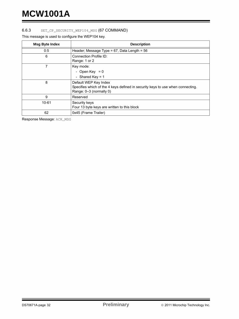
6.6.3 SET_CP_SECURITY_WEP104_MSG (67 COMMAND)This message is used to configure the WEP104 key.Response Message: ACK_MSG
Msg Byte Index Description
0:5 Header; Message Type = 67, Data Length = 566 Connection Profile ID:
Range: 1 or 27 Key mode:
- Open Key = 0- Shared Key = 1
8 Default WEP Key IndexSpecifies which of the 4 keys defined in security keys to use when connecting. Range: 0–3 (normally 0)
9 Reserved10-61 Security keys
Four 13 byte keys are written to this block62 0x45 (Frame Trailer)
DS70671A-page 32 Preliminary © 2011 Microchip Technology Inc.

MCW1001A
6.6.4 SET_CP_SECURITY_WPA_MSG (68 Command)This message is used to configure WiComm-Socket to use either WPA or WPA2 wireless security.Response Message: ACK_MSG
6.6.5 GET_CP_WPAKEY_MSG (71 COMMAND)Message sent from the Host to WiComm-Socket to determine the calculated PSK key. After a connection has been established with a WPA passphrase, this command can be used to read the 32 byte calculated key from WiComm-Socket. The Host can then store this key for use at a later time in security modes 3, 5 or 7 to avoid the 30 second key calculation step described above in future connections.
Response Message: WPAKEY_RESPONSE_MSG
Msg Byte Index Description
0:5 Header; Message Type = 68, Data Length = Security key Length + 46 Connection Profile ID:
Range: 1 or 27 Security Type
Value Description 3 Use WPA security.
Binary Pre-shared Key (PSK) key will be provided in security key
4 Use WPA security. ASCII WPA pass phrase will be provided in security key and while connecting the MRF24WB0M will calculate the PSK key (which can take up to 30 seconds)
5 Use WPA-2 security. Binary WPA-2 key will be provided in security Key
6 Use WPA-2 security.ASCII WPA-2 pass phrase will be provided in security Key, and while connecting, the MRF24WB0M will calculate the PSK key (which can take up to 30 seconds).
7 Same as (3) and (5), except WiComm-Socket connects to the AP using highest level security that the AP supports (WPA or WPA2).
8 Same as (4) and (6), except connection manager connects to the AP using highest level security the AP supports (WPA or WPA2).
Note: When using an ASCII pass phrase instead of a binary key, WiComm-Socket, when connecting, will take approximately 30 (TBD) seconds to calculate the binary key.
8 Reserved9 Security key Length
Number of bytes in security key field (1–64)10:N + 9 Security key
Either the binary key bytes or the pass phrase bytes. The length of this field must be equal to security key length
N + 10 0x45 (Frame Trailer)
Msg Byte Index Description
0:5 Header; Message Type = 71, Data Length = 26 Connection Profile ID:
Range: 1 or 27 Reserved8 0x45 (Frame Trailer)
© 2011 Microchip Technology Inc. Preliminary DS70671A-page 33

MCW1001A
6.6.6 WPAKEY_RESPONSE_MSG (49 RESPONSE)This response contains the 32 byte security key calculated from the SSID and passphrase by WiComm-Socket. This value is only valid if a connection based on the supplied passphrase has been made in one of the WPA security modes.Msg Byte Index Description
0:5 Header; Message Type = 49, Data Length = 326:37 Security Key (32 bytes)38 0x45 (Frame Trailer)
DS70671A-page 34 Preliminary © 2011 Microchip Technology Inc.

MCW1001A
6.7 Wi-Fi Scanning Messages6.7.1 SCAN_START_MSG (80 COMMAND)This message directs WiComm-Socket to scan for access points (APs) using the settings from the specified CP. The immediate response to this message is the ACK_MSG. After the FTP operation has completed the EVENT_MSG – Wi-Fi Scan Results Ready will be sent to the host CPU. The scan results can then be retrieved through the SCAN_GET_RESULTS_MSG. Note that Scan may only be performed in the disconnected state, and when a scan is in process, the only command WiComm-Socket will accept is the reboot command.
Response Message: ACK_MSG
6.7.2 SCAN_GET_RESULTS_MSG (81 COMMAND)This message is used to retrieve the scan results from the most recent scan. It can be called after the EVENT_MSG – Wi-Fi Scan Results Ready is received.
Response Message: SCAN_RESULT_MSG
Msg Byte Index Description
0:5 Header; Message Type = 80, Data Length = 26 Connection Profile ID:
- Range: 1 or 2 [select defined CP]- 0xFF [scan everything]
If using a defined CP, then the criteria within that CP will be used for the scan (for example: scan for that CP's SSID using the CP's channel list). If the CP is infrastructure then only scan results from infrastructure networks are reported. If the CP is ad hoc then only scan results from ad hoc networks are reported.
If the field is set to 0xFF then WiComm-Socket will scan all channels within its regional domain and report all results in infrastructure and ad hoc networks.
7 Reserved8 0x45 (Frame Trailer)
Msg Byte Index Description
0:5 Header; Message Type = 81, Data Length = 26 List Index
The index within the WiComm-Socket scan list The valid range is: 0 Number of Scan results – 1 (from the EVENT_MSG – Wi-Fi Scan Results Ready)
7 Reserved8 0x45 (Frame Trailer)
© 2011 Microchip Technology Inc. Preliminary DS70671A-page 35

MCW1001A
6.7.3 SCAN_RESULT_MSG (22 RESPONSE)This message is sent in response to the SCAN_GET_RESULTS_MSG.Msg Byte Index Description
0:5 Header; Message Type = 22, Data Length = 576:11 BSSID12 SSID Length
Number of valid SSID characters that follow13:44 SSID
45 AP configuration (8 bits)This byte is defined as follows:7 6 5 4 3 2 1 0
WPA2 WPA Preamble Privacy Res Res Res IE
IE 1 if AP broadcasting one or more information elements, otherwise 0Res ReservedPrivacy 0: AP is open (no security)
1: AP using security; if neither WPA or WPA2 is set then security is WEP.Preamble 0: AP transmitting with short preamble
1: AP transmitting with long preambleWPA Only valid if Privacy is 1.
0: AP does not support WPA1: AP supports WPA
WPA2 Only valid if Privacy is 1.0: AP does not support WPA21: AP supports WPA2
46:47 Beacon Period Network beacon interval
48:49 ATIM Window Only valid if BSS Type is ad hoc
50:57 Basic Rates, each 1 byte, in the following format: Bit 7:0: Rate is not part of the “basic rates set” 1: Rate is part of the “basic rates set” Bits 6:0: Multiple of 500 kbps giving the supported rate. For example, a value of 2 (2x500 kbps) indicates that 1 Mbps is a supported rate. A value of 4 in this field indicates a 2 Mbps rate (4x500 kbps).
58 RSSI of received beacon or probe response59 Basic Rate List Length
Number of basic rates that are valid in above basic rate list60 DTIM period (1 byte)
Part of TIM element61 BSS Type (1 byte)
1: Infrastructure 2: ad hoc
62 Channel number (1 byte)63 0x45 (Frame Trailer)
DS70671A-page 36 Preliminary © 2011 Microchip Technology Inc.

MCW1001A
6.8 Wi-Fi Connection MessagesThe messages in this section are used to initiate the connection to a Wi-Fi network, or to disconnect an existing con-nection.6.8.1 Wi-Fi_CONNECT_MSG (90 COMMAND)This message directs WiComm-Socket to initiate a Wi-Fi connection process as defined in the specified CP. WiComm-Socket will send an ACK_MSG in response to this message. After the connection succeeds or fails, an EVENT_MSG will asynchronously be sent from WiComm-Socket to the CPU host.
Response Message: ACK_MSG
6.8.2 Wi-Fi_DISCONNECT_MSG (91 COMMAND)This message will cause WiComm-Socket to close its existing Wi-Fi connection. WiCom-Socket will send an ACK_MSGin response to this message. After the connection has been closed an EVENT_MSG will be sent to notify the host CPU.
Response Message: ACK_MSG
Msg Byte Index Description
0:5 Header; Message Type = 90, Data Length = 26 Connection Profile ID to connect to
Range: 1 or 27 Reserved8 0x45 (Frame Trailer)
Msg Byte Index Description
0:5 Header; Message Type = 91, Data Length = 06 0x45 (Frame Trailer)
© 2011 Microchip Technology Inc. Preliminary DS70671A-page 37
MCW1001A
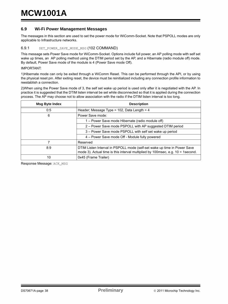
6.9 Wi-Fi Power Management MessagesThe messages in this section are used to set the power mode for WiComm-Socket. Note that PSPOLL modes are only applicable to Infrastructure networks.6.9.1 SET_POWER_SAVE_MODE_MSG (102 COMMAND)This message sets Power Save mode for WiComm-Socket. Options include full power, an AP polling mode with self set wake up times, an AP polling method using the DTIM period set by the AP, and a Hibernate (radio module off) mode. By default, Power Save mode of the module is 4 (Power Save mode Off).
IMPORTANT:
1)Hibernate mode can only be exited through a WiComm Reset. This can be performed through the API, or by using the physical reset pin. After exiting reset, the device must be reinitialized including any connection profile information to reestablish a connection.
2)When using the Power Save mode of 3, the self set wake up period is used only after it is negotiated with the AP. In practice it is suggested that the DTIM listen interval be set while disconnected so that it is applied during the connection process. The AP may choose not to allow association with the radio if the DTIM listen interval is too long.
Response Message: ACK_MSG
Msg Byte Index Description
0:5 Header; Message Type = 102, Data Length = 46 Power Save mode:
1 – Power Save mode Hibernate (radio module off) 2 – Power Save mode PSPOLL with AP suggested DTIM period 3 – Power Save mode PSPOLL with self set wake up period 4 – Power Save mode Off - Module fully powered
7 Reserved8:9 DTIM Listen Interval in PSPOLL mode (self-set wake up time in Power Save
mode 3). Actual time is this interval multiplied by 100msec, e.g. 10 = 1second. 10 0x45 (Frame Trailer)
DS70671A-page 38 Preliminary © 2011 Microchip Technology Inc.

MCW1001A
6.10 ICMP (Ping) Messages6.10.1 PING_SEND_MSG (121 COMMAND)This message sends a ping to a remote host. The immediate response to this message is an ACK_MSG. When WiComm-Socket receives a ping response, or times out waiting for a ping response, it will send the EVENT_MSG – Ping Response Event (see Section 6.12.2.4, EVENT_MSG – Ping Response Event (1-26 Async) to the host. In the current version of WiComm-Socket, the time-out value is fixed at 4 seconds.
Response Message: ACK_MSG (followed later by EVENT_MSG – Ping Response Event)
Msg Byte Index Description
0:5 Header; Message Type = 121, Data Length = 166:21 Remote IP Address to ping22 0x45 (Frame Trailer)
© 2011 Microchip Technology Inc. Preliminary DS70671A-page 39

MCW1001A
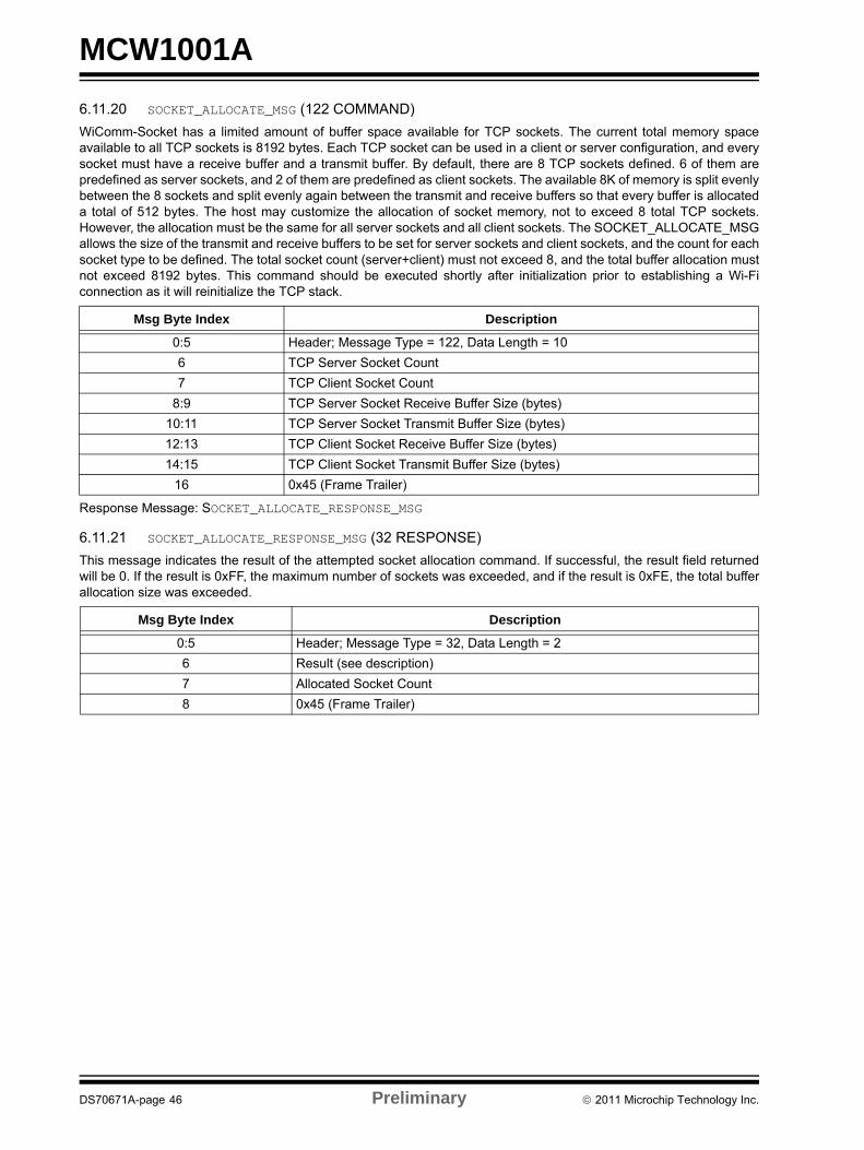
6.11 Socket Messages6.11.1 SOCKET_CREATE_MSG (110 COMMAND)This message attempts to create a TCP or UDP socket.
Response Message: SOCKET_CREATE_RESPONSE_MSG
6.11.2 SOCKET_CREATE_RESPONSE_MSG (23 RESPONSE)This message indicates the result of the attempted socket created by returning a “handle” to the socket. If a socket is not created, WiComm-Socket will return 0xFE as the handle or 0xFF if the socket type was unknown (not 0 or 1 in above message).
6.11.3 SOCKET_CLOSE_MSG (111 COMMAND)This message attempts to close a previously created TCP or UDP socket.
Response Message: ACK_MSG (may generate an asynchronous Error Event if socket close failed)
Msg Byte Index Description
0:5 Header; Message Type = 110, Data Length = 26 Socket Type:
• 0 – UDP• 1 – TCP
7 Reserved8 0x45 (Frame Trailer)
Msg Byte Index Description
0:5 Header; Message Type = 23, Data Length = 26 Socket Handle:
0–253 – Valid Socket handle 254 – Invalid Socket 255 – Unknown Socket Type
7 Reserved8 0x45 (Frame Trailer)
Msg Byte Index Description
0:5 Header; Message Type = 111, Data Length = 26 Socket Handle7 Reserved8 0x45 (Frame Trailer)
DS70671A-page 40 Preliminary © 2011 Microchip Technology Inc.

MCW1001A
6.11.4 SOCKET_BIND_MSG (112 Command)The Bind command associates a local IP address and port with a socket. This information allows the socket to advertise its presence. As WiComm-Socket is always associated with only one local IP address, it is not required to supply the local IP address in the Bind command. If the object of the bind process is a UDP socket, WiComm-Socket will attempt to open the UDP port to remote connections. In this mode, the UDP socket can function as a server to accept client messages which can be subsequently read from the socket. If this open process for the UDP port fails, the bind response will return unsuccessful. It is not required to bind a UDP socket if its only purpose is to transmit as a client, or if it will transmit before receiving from a remote connection. If the local port number is specified as zero, WiComm-Socket will assign a non-zero value to the port beginning with 1024.Response Message: SOCKET_BIND_RESPONSE_MSG
6.11.5 SOCKET_BIND_RESPONSE_MSG (24 Response)This message indicates the result of the attempted socket bind as either successful (0) or not (0xFF).
6.11.6 SOCKET_CONNECT_MSG (113 Command)For TCP sockets, the Connect command attempts to establish a connection between two sockets. For UDP sockets, the Connect command specifies the peer or remote endpoint for the socket. The socket parameter specifies the local socket to be used, and the remote address and port specify the peer or remote socket to connect. The Connect command will perform an implicit bind for UDP sockets if not done previously. The Connect command is non-blocking and will return immediately with a result of either Success (0), Connection In Process (0xFE), or Error (0xFF).
Response Message: SOCKET_CONNECT_RESPONSE_MSG
Msg Byte Index Description
0:5 Header; Message Type = 112, Data Length = 46:7 Local Port Number to be associated with this socket8 Socket Handle (previously created with SOCKET_CREATE_MSG)9 Reserved10 0x45 (Frame Trailer)
Msg Byte Index Description
0:5 Header; Message Type = 24, Data Length = 46:7 Local Port Number bound to8 Bind Result:
0 – Success1-255 – Unsuccessful Bind
9 Reserved10 0x45 (Frame Trailer)
Msg Byte Index Description
0:5 Header; Message Type = 113, Data Length = 206 Socket Handle (previously created with SOCKET_CREATE_MSG)7 Reserved
8:9 Remote Port Number to connect to10:25 Remote IP address – for IPv4 the first 4 bytes are the IP address
26 0x45 (Frame Trailer)
© 2011 Microchip Technology Inc. Preliminary DS70671A-page 41

MCW1001A
6.11.7 SOCKET_CONNECT_RESPONSE_MSG (25 Response)This message indicates the result of the attempted socket connect.6.11.8 SOCKET_LISTEN_MSG (114 Command)For TCP sockets, the Listen command makes the socket passive. After the socket becomes passive, it cannot be used to initiate connection requests to remote servers (connect cannot be used on a listening socket). For UDP sockets, this function has no meaning. The socket handle parameter specifies the local socket to be used for listening that has been previously created and bound with the SOCKET_CREATE_MSG and the SOCKET_BIND_MSG. The backlog parameter specifies the number of connections to make available to remote clients. Each of these uses a limited number of WiComm-Socket server socket. The return value will indicate how many server sockets were actually allocated by returning the modified backlog count. For instance, if a socket is set into Listen mode with a backlog parameter of 5, and the backlog return value in the response is 3, there were 2 server sockets allocated. This command may be issued to a socket that is already listening, and if it is possible for more sockets to be opened based on the current socket backlog, the allocations will be performed.
Response Message: SOCKET_LISTEN_RESPONSE_MSG
6.11.9 SOCKET_LISTEN_RESPONSE_MSG (26 RESPONSE)This message indicates the result of the attempted socket Listen command.
Msg Byte Index Description
0:5 Header; Message Type = 25, Data Length = 26 Socket connect result:
0 – Success254 – Socket connect in process255 – Socket connect failed
7 Reserved8 0x45 (Frame Trailer)
Msg Byte Index Description
0:5 Header; Message Type = 114, Data Length = 26 Socket Handle (previously created with SOCKET_CREATE_MSG)7 Server socket count (backlog)8 0x45 (Frame Trailer)
Msg Byte Index Description
0:5 Header; Message Type = 26, Data Length = 26 Socket connect result:
0 – Success254 – Socket connect in process255 – Socket connect failed
7 New Unassigned backlog count8 0x45 (Frame Trailer)
DS70671A-page 42 Preliminary © 2011 Microchip Technology Inc.

MCW1001A
6.11.10 SOCKET_ACCEPT_MSG (115 COMMAND)For TCP sockets, the Accept command will indicate a connected server socket by returning the local server socket num-ber of a remote client connection.Response Message: SOCKET_ACCEPT_RESPONSE_MSG
6.11.11 SOCKET_ACCEPT_RESPONSE_MSG (27 RESPONSE)This message indicates the result of the attempted socket Accept command.
6.11.12 SOCKET_SEND_MSG (116 COMMAND)The Send command sends data on the target socket. The remote connection is not defined in the call to this function, but instead it relies on the socket having been connected prior to the send. In the case of a memory limited WiComm-Socket, the host may need to limit the size of the data sent in each command. A facility will be provided to allow messages to be fragmented by the host and reassembled in WiComm-Socket to create a complete packet.
Response Message: SOCKET_SEND_RESPONSE_MSG
6.11.13 SOCKET_SEND_RESPONSE_MSG (28 RESPONSE)This message indicates the result of the attempted socket Sendto command.
Msg Byte Index Description
0:5 Header; Message Type = 115, Data Length =26 Socket Handle (previously created with SOCKET_CREATE_MSG)7 Reserved8 0x45 (Frame Trailer)
Msg Byte Index Description
0:5 Header; Message Type = 27, Data Length = 46 Socket Handle value returned - If the value is 0xFF, the connection is not valid7 Reserved
8:9 Remote Port Number10:25 Remote IP address – for IPv4 the first 4 bytes are the IP address
26 0x45 (Frame Trailer)
Msg Byte Index Description
0:5 Header; Message Type = 116, Data Length = 4 + N Data Bytes6 Socket Handle (previously created with SOCKET_CREATE_MSG and connected)7 Reserved
8:9 Data byte count (N)10:N+9 N bytes of data to be sentN+10 0x45 (Frame Trailer)
Msg Byte Index Description
0:5 Header; Message Type = 28, Data Length = 26:7 Socket byte count sent8 0x45 (Frame Trailer)
© 2011 Microchip Technology Inc. Preliminary DS70671A-page 43

MCW1001A
6.11.14 SOCKET_RECV_MSG (117 COMMAND)The Recv command attempts to read data from an open socket. In this version of WiComm-Socket, the Recv command is always non-blocking, but UDP received data is not buffered in WiComm-Socket. If data is available to be read from the socket, the amount of data available will be returned (not to exceed the specified buffer size in the call). If no data is available, the RECV response will return 0 as the received count. As a result of non-buffered approach to UDP receive buffers, WiComm-Socket uses an asynchronous SOCKET_RECV_FROM_RESPONSE_MSG to report any data received on a bound UDP listener socket. In this way, the SOCKET_RECV_MSG is not typically used to poll for UDP socket received data and by design, a call to this function on a UDP socket will return 0 bytes read.Response Message: SOCKET_RECV_RESPONSE_MSG
6.11.15 SOCKET_RECV_RESPONSE_MSG (29 RESPONSE)This message indicates the result of the attempted socket receive message.
6.11.16 SOCKET_SEND_TO_MSG (118 COMMAND)The Sendto command sends data on the target socket. Unlike the socket Send command, the remote connection is defined in the call to this function. By specifying the remote address and port, the connection can be created if it does not exist. In the case of a memory limited WiComm-Socket, the host may need to limit the size of the data sent in each command. A facility will be provided to allow messages to be fragmented by the host and reassembled in WiComm-Socket to create a complete packet.
Response Message: SOCKET_SEND_TO_RESPONSE_MSG
Msg Byte Index Description
0:5 Header; Message Type = 117, Data Length = 46 Socket Handle (previously created with SOCKET_CREATE_MSG)7 Reserved
8:9 Amount of data to be read 10 0x45 (Frame Trailer)
Msg Byte Index Description
0:5 Header; Message Type = 29, Data Length = 4 + N Data Bytes6 Socket Handle (used when data was read)7 Reserved
8:9 Byte count received (N)10:N + 9 N bytes of data readN + 10 0x45 (Frame Trailer)
Msg Byte Index Description
0:5 Header; Message Type = 118, Data Length = 22 + N Data Bytes6 Socket Handle (previously created with SOCKET_CREATE_MSG)7 Reserved
8:9 Remote Port Number to send the data to10:25 Remote IP address – for IPv4 the first 4 bytes are the IP address26:27 Data byte count (N)
28:N + 27 N bytes of data to be sentN + 28 0x45 (Frame Trailer)
DS70671A-page 44 Preliminary © 2011 Microchip Technology Inc.

MCW1001A
6.11.17 SOCKET_SEND_TO_RESPONSE_MSG (30 RESPONSE)This message indicates the result of the attempted socket Sendto command. If successful, the number of bytes trans-ferred will be returned. If unsuccessful, an ACK_MSG will be returned with a subsequent asynchronous Error event mes-sage.6.11.18 SOCKET_RECV_FROM_MSG (119 COMMAND)The RecvFrom command attempts to read data from an open socket. It is normally used with UDP sockets as the return values include the source address of the received data. In this version of WiComm-Socket, the RecvFrom command is always non-blocking, but UDP received data is not buffered in WiComm-Socket. If data is available to be read from the socket, the amount of data available will be returned (not to exceed the specified buffer size in the call). If no data is available, the RecvFrom response will return 0 as the received count. As a result of the non-buffered approach to UDP receive buffers, WiComm-Socket uses an asynchronous SOCKET_RECV_FROM_RESPONSE_MSG to report any data received on a bound UDP listener socket. In this way, the SOCKET_RECV_FROM_MSG is not typically used to poll for UDP socket received data and by design, a call to this function on a UDP socket will return 0 bytes read.
Response Message: SOCKET_RECV_FROM_RESPONSE_MSG
6.11.19 SOCKET_RECV_FROM_RESPONSE_MSG (31 RESPONSE)This message indicates the result of the attempted socket RecvFrom command. The number of bytes transferred will be returned (can be zero).
Msg Byte Index Description
0:5 Header; Message Type = 30, Data Length = 26:7 Byte count sent8 0x45 (Frame Trailer)
Msg Byte Index Description
0:5 Header; Message Type = 119, Data Length = 46 Socket Handle (previously created with SOCKET_CREATE_MSG)7 Reserved
8:9 Amount of data to be read 10 0x45 (Frame Trailer)
Msg Byte Index Description
0:5 Header; Message Type = 31, Data Length = 22 + N Data Bytes6 Socket Handle (used when data was read)7 Reserved
8:9 Port number of sender10:25 IP Address of sender26:27 Byte count received (N)
28:N + 27 N bytes of data readN + 28 0x45 (Frame Trailer)
© 2011 Microchip Technology Inc. Preliminary DS70671A-page 45
MCW1001A
6.11.20 SOCKET_ALLOCATE_MSG (122 COMMAND)WiComm-Socket has a limited amount of buffer space available for TCP sockets. The current total memory space available to all TCP sockets is 8192 bytes. Each TCP socket can be used in a client or server configuration, and every socket must have a receive buffer and a transmit buffer. By default, there are 8 TCP sockets defined. 6 of them are predefined as server sockets, and 2 of them are predefined as client sockets. The available 8K of memory is split evenly between the 8 sockets and split evenly again between the transmit and receive buffers so that every buffer is allocated a total of 512 bytes. The host may customize the allocation of socket memory, not to exceed 8 total TCP sockets. However, the allocation must be the same for all server sockets and all client sockets. The SOCKET_ALLOCATE_MSG allows the size of the transmit and receive buffers to be set for server sockets and client sockets, and the count for each socket type to be defined. The total socket count (server+client) must not exceed 8, and the total buffer allocation must not exceed 8192 bytes. This command should be executed shortly after initialization prior to establishing a Wi-Fi connection as it will reinitialize the TCP stack.Response Message: SOCKET_ALLOCATE_RESPONSE_MSG
6.11.21 SOCKET_ALLOCATE_RESPONSE_MSG (32 RESPONSE)This message indicates the result of the attempted socket allocation command. If successful, the result field returned will be 0. If the result is 0xFF, the maximum number of sockets was exceeded, and if the result is 0xFE, the total buffer allocation size was exceeded.
Msg Byte Index Description
0:5 Header; Message Type = 122, Data Length = 106 TCP Server Socket Count7 TCP Client Socket Count
8:9 TCP Server Socket Receive Buffer Size (bytes)10:11 TCP Server Socket Transmit Buffer Size (bytes)12:13 TCP Client Socket Receive Buffer Size (bytes)14:15 TCP Client Socket Transmit Buffer Size (bytes)
16 0x45 (Frame Trailer)
Msg Byte Index Description
0:5 Header; Message Type = 32, Data Length = 26 Result (see description)7 Allocated Socket Count8 0x45 (Frame Trailer)
DS70671A-page 46 Preliminary © 2011 Microchip Technology Inc.
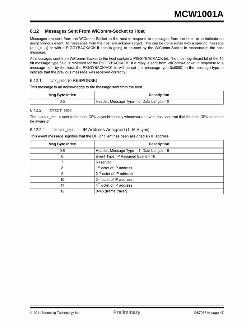
MCW1001A
6.12 Messages Sent From WiComm-Socket to HostMessages are sent from the WiComm-Socket to the host to respond to messages from the host, or to indicate an asynchronous event. All messages from the host are acknowledged. This can be done either with a specific message (ACK_MSG) or with a PIGGYBACKACK if data is going to be sent by the WiComm-Socket in response to the host message.All messages sent from WiComm-Socket to the host contain a PIGGYBACKACK bit. The most significant bit of the 16 bit message type field is reserved for the PIGGYBACKACK. If a reply is sent from WiComm-Socket in response to a message sent by the host, the PIGGYBACKACK bit will be set (i.e. message type 0x8000) in the message type to indicate that the previous message was received correctly.
6.12.1 ACK_MSG (0 RESPONSE)This message is an acknowledge to the message sent from the host.
6.12.2 EVENT_MSG
The EVENT_MSG is sent to the host CPU asynchronously whenever an event has occurred that the host CPU needs to be aware of.
6.12.2.1 EVENT_MSG – IP Address Assigned (1-16 Async)This event message signifies that the DHCP client has been assigned an IP address.
Msg Byte Index Description
0:5 Header; Message Type = 0, Data Length = 0
Msg Byte Index Description
0:5 Header; Message Type = 1, Data Length = 66 Event Type: IP Assigned Event = 167 Reserved8 1st octet of IP address9 2nd octet of IP address
10 3rd octet of IP address11 4th octet of IP address12 0x45 (frame trailer)
© 2011 Microchip Technology Inc. Preliminary DS70671A-page 47

MCW1001A
6.12.2.2 EVENT_MSG – Wi-Fi Connection Status Changed (1-8 Async)This event message signifies a change in the Wi-Fi connection status.6.12.2.3 EVENT_MSG – Wi-Fi Scan Results Ready (1-9 Async)This event message signifies that the scan results are ready.
Msg Byte Index Description
0:5 Header; Message Type = 1, Data Length = 46 Event Type: Wi-Fi Connection Status Event = 87 Event Status:
1: Connection attempt succeeded 2: Connection attempt failed 3: Connection temporarily lost, WiComm-Socket is retrying 4: Connection reestablished, WiComm-Socket reestablished the link 5: Connection permanently lost, retries exhausted
8 Event Data (not always used)If Status equals The Optional Data signifies
1 Optional data field not used2 Reason that connection failed
Join failure 2Authentication failure 3Association failure 4WEP handshake failure 5PSK calculation failure 6PSK handshake failure 7ad hoc join failure 8Security mismatch failure 9No suitable AP found failure 10Retry forever not supported failure 11
3 Reason that connection was temporarily lostBeacon time out 1Deauth ReceivedDE 2Disassociate received 3
4 Optional data field not used5 Reason that connection was permanently lost:
Same as when status equals 39 Reserved10 0x45 (frame trailer)
Msg Byte Index Description
0:5 Header; Message Type = 1, Data Length = 26 Event Type: Wi-Fi Scan Results Ready Event = 97 Number of Scan Results
The number of Scan Results8 0x45 (frame trailer)
DS70671A-page 48 Preliminary © 2011 Microchip Technology Inc.

MCW1001A
6.12.2.4 EVENT_MSG – Ping Response Event (1-26 Async)This event message is sent to the host when either a ping response is received, or WiComm-Socket has timed-out wait-ing for a ping response. See Section 6.10.1, PING_SEND_MSG (121 Command)6.12.2.5 EVENT_MSG – Error Event (1-255 Async)This event is sent to the host to report an error condition.
Msg Byte Index Description
0:5 Header; Message Type = 1, Data Length = 46 Event Type: Ping Response Event = 267 Ping Response Status:
0 – valid ping response was received 1 – ping response time out
8:9 Response time in milliseconds10 0x45 (frame trailer)
Msg Byte Index Description
0:5 Header; Message Type = 1, Data Length = 86 Event Type: Error Event = 2557 Reserved
8:9 Error Type: 60 – Baud rate generator error61 – Invalid Connection Profile ID62 – Wi-Fi already connected error63 – Wi-Fi already disconnected error64 – Close socket failed error65 – Socket Sendto Time out Error (ARP request Timed Out)66 – Scan Index Out of Range Error67 – ICMP Ping Flood Error68 – ICMP Ping In Use Error69 – Socket RecvFrom Failed 71 – Serial Transmit Buffer Allocation Error72 – General Assert Error73 – Invalid Powersave Mode Error74 – Busy (Hibernate Mode) Error75 – Busy (Scan Mode) Error
10:13 Error Data:Error details if applicable
14 0x45 (frame trailer)
© 2011 Microchip Technology Inc. Preliminary DS70671A-page 49

MCW1001A
6.12.3 EVENT_MSG – STARTUP EVENT (1-27 ASYNC)This event is sent to the host to indicate that WiComm-Socket has started.Msg Byte Index Description
0:5 Header; Message Type = 1, Data Length = 66 Event Type: Startup Event = 277 Startup Condition BitMask:
0x01 – Power On Reset 0x02 – Brown Out Reset 0x04 – Idle Reset 0x08 – Sleep Reset 0x10 – Watchdog Reset 0x40 – Software Reset 0x80 – External Resete.g. 0x11 = Power on and Watchdog Reset
8:9 WiComm-Socket Version10:11 Radio Version
12 0x45 (frame trailer)
DS70671A-page 50 Preliminary © 2011 Microchip Technology Inc.
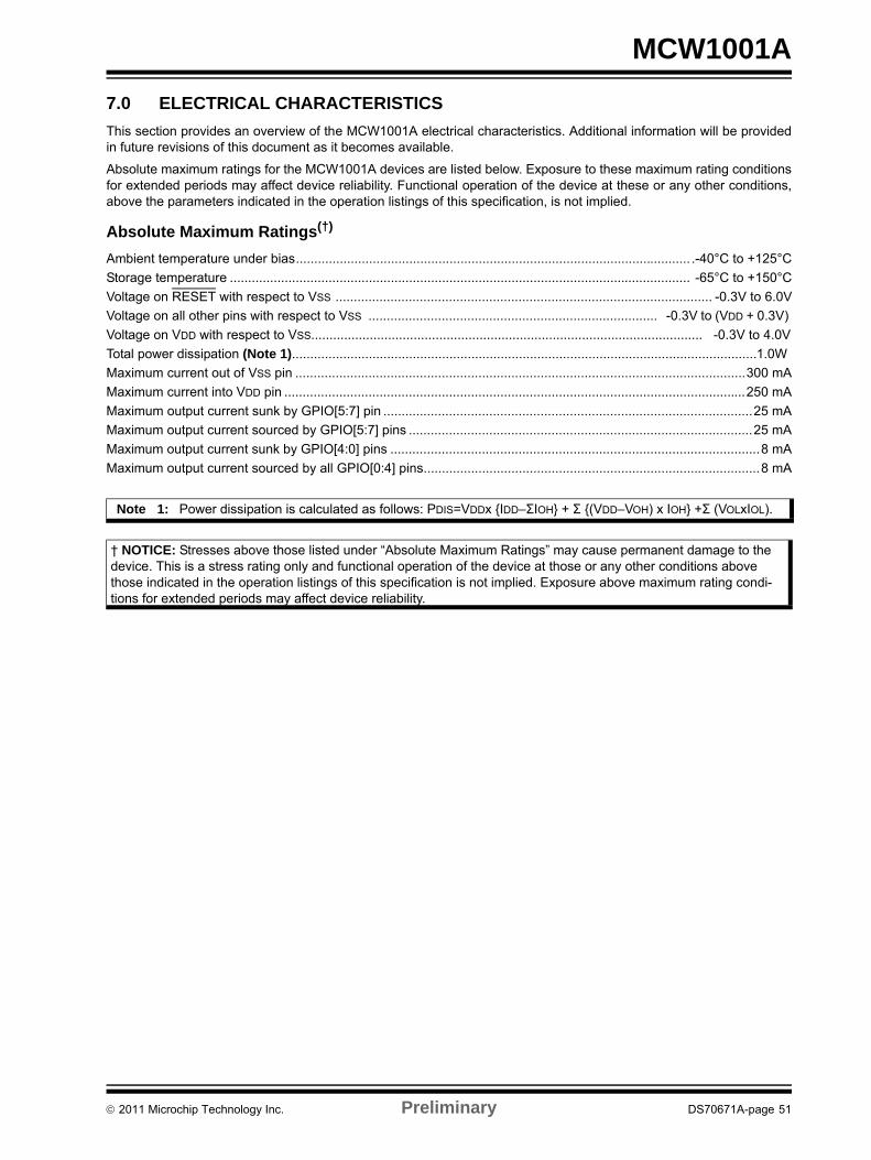
MCW1001A
7.0 ELECTRICAL CHARACTERISTICSThis section provides an overview of the MCW1001A electrical characteristics. Additional information will be provided in future revisions of this document as it becomes available.Absolute maximum ratings for the MCW1001A devices are listed below. Exposure to these maximum rating conditions for extended periods may affect device reliability. Functional operation of the device at these or any other conditions, above the parameters indicated in the operation listings of this specification, is not implied.
Absolute Maximum Ratings(†) Ambient temperature under bias............................................................................................................ .-40°C to +125°CStorage temperature .............................................................................................................................. -65°C to +150°CVoltage on RESET with respect to VSS ....................................................................................................... -0.3V to 6.0VVoltage on all other pins with respect to VSS ............................................................................... -0.3V to (VDD + 0.3V) Voltage on VDD with respect to VSS........................................................................................................... -0.3V to 4.0VTotal power dissipation (Note 1)...............................................................................................................................1.0W Maximum current out of VSS pin ...........................................................................................................................300 mAMaximum current into VDD pin ..............................................................................................................................250 mAMaximum output current sunk by GPIO[5:7] pin .....................................................................................................25 mAMaximum output current sourced by GPIO[5:7] pins ..............................................................................................25 mAMaximum output current sunk by GPIO[4:0] pins .....................................................................................................8 mAMaximum output current sourced by all GPIO[0:4] pins............................................................................................8 mA
Note 1: Power dissipation is calculated as follows: PDIS=VDDx IDD–ΣIOH + Σ (VDD–VOH) x IOH +Σ (VOLxIOL).
† NOTICE: Stresses above those listed under “Absolute Maximum Ratings” may cause permanent damage to the device. This is a stress rating only and functional operation of the device at those or any other conditions above those indicated in the operation listings of this specification is not implied. Exposure above maximum rating condi-tions for extended periods may affect device reliability.
© 2011 Microchip Technology Inc. Preliminary DS70671A-page 51

MCW1001A
7.1 DC CharacteristicsTABLE 7-1: DC TEMPERATURE AND VOLTAGE SPECIFICATIONS
DC CHARACTERISTICS Operating Conditions (unless otherwise indicated): 3.0V ≤ VDD ≤ 5.5V at -40°C ≤ TA ≤ +85°C (I-Temp)
Param. No.
Characteristics Symbol Min. Typical Max. Units Conditions
D001 Supply voltage VDD 2.15 — 3.6 V —VDD start voltage to ensure internal Power-on reset signal
VPOR — — 0.7 V —
— — — — — — —D003 VDD Rise rate to ensure
Power-on resetSVDD 0.05 — — V/ms Design guidance only not
testedD004 Supply current IDD — — — — —
VDD = 3.0V — — 10 12 mA FOSC = 12 MHz (330 nF on VUSB)VDD = 5.0V — — 13 15 mA
Input Low-VoltageD031 Schmitt Trigger (GPIO) VIL — — 0.2 VDD V 3.0V ≤ VDD ≤ 5.5V
TTL (UCTS pin) — — 0.8 4.5V ≤ VDD ≤ 5.5VInput High-Voltage
D041 Schmitt Trigger (GPIO) VIH 0.8 VDD — VDD V 3.0V ≤ VDD ≤ 5.5VTTL (URTS pin) 2.0 — VDD 4.5V ≤ VDD ≤ 5.5V
Input Leakage currentD060 GPIO, UCTS IIL — ±50 ±100 nA VSS ≤ VPIN ≤ VDD, pin at Hi-Z
URTS — ±50 ±200OSC1 — ±50 ±100
Output Low-VoltageD080 GPIO VOL — — 0.6 V IOL = 8.0 mA, VDD = 0.5V
— — 0.6 IOL = -6.0 mA, VDD = 3.3VOutput High-Voltage
D090 GPIO VOH VDD - 0.7 — — V IOL = -3.5 mA, VDD = 5.0VVDD - 0.7 — — IOL = -3.0 mA, VDD = 3.3V
Capacitance Loading Specs on Output PinsD101 OSC2 COSC2 — — 15 pF Note 1D102 GPIO CIO — — 50 pF Note 1
Note 1: This parameter is characterized, but not tested.
DS70671A-page 52 Preliminary © 2011 Microchip Technology Inc.
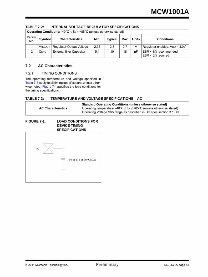
MCW1001A
7.2 AC Characteristics
7.2.1 TIMING CONDITIONSThe operating temperature and voltage specified in Table 7-3 apply to all timing specifications unless other-wise noted. Figure 7-1specifies the load conditions for the timing specifications.
TABLE 7-3: TEMPERATURE AND VOLTAGE SPECIFICATIONS – AC
FIGURE 7-1: LOAD CONDITIONS FOR DEVICE TIMING SPECIFICATIONS
TABLE 7-2: INTERNAL VOLTAGE REGULATOR SPECIFICATIONSOperating Conditions: -40°C < TA < +85°C (unless otherwise stated)
Param. No. Symbol Characteristics Min. Typical Max. Units Conditions
1 VRGOUT Regulator Output Voltage 2.35 2.5 2.7 V Regulator enabled, VDD = 3.0V2 CEFC External filter Capacitor 5.4 10 18 µF ESR < 3Ω recommended
ESR < 5Ω required
AC CharacteristicsStandard Operating Conditions (unless otherwise stated)Operating temperature: -40°C ≤ TA ≤ +85°C (unless otherwise stated) Operating Voltage VDD range as described in DC spec section 3.1 DC.
50 pF (15 pF for OSC2)
Pin
© 2011 Microchip Technology Inc. Preliminary DS70671A-page 53
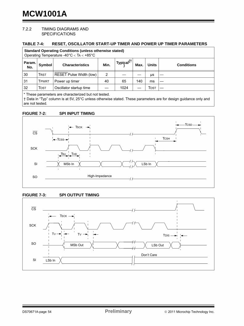
MCW1001A
7.2.2 TIMING DIAGRAMS ANDSPECIFICATIONS
TABLE 7-4: RESET, OSCILLATOR START-UP TIMER AND POWER UP TIMER PARAMETERS
FIGURE 7-2: SPI INPUT TIMING
FIGURE 7-3: SPI OUTPUT TIMING
Standard Operating Conditions (unless otherwise stated) Operating Temperature -40°C < TA < +85°C
Param. No. Symbol Characteristics Min. Typical(†
) Max. Units Conditions
30 TRST RESET Pulse Width (low) 2 — — µs —
31 TPWRT Power up timer 40 65 140 ms —
32 TOST Oscillator startup time — 1024 — TOST —
* These parameters are characterized but not tested.† Data in “Typ” column is at 5V, 25°C unless otherwise stated. These parameters are for design guidance only and are not tested.
CS
SCK
SI
SO
TCSS
THDTSU
TCSD
LSb InMSb In
High-Impedance
TCSH
TSCK
CS
SCK
SO MSb Out LSb Out
TDIS
Don’t CareSI
TV TV
LSb In
TSCK
DS70671A-page 54 Preliminary © 2011 Microchip Technology Inc.

MCW1001A
TABLE 7-5: SPI INTERFACE AC CHARACTERISTICSSymbol Parameters Min. Max. Units
TSCK SCK Period 40 — nSTCSD CS High Time 50 — nSTCSS CS Setup Time 50 — nSTCSH CS Hold Time 50 — nSTSU SDI Setup Time 10 — nSTHD SDI Hold Time 10 — nSTV SDO Valid time — 15 nS
© 2011 Microchip Technology Inc. Preliminary DS70671A-page 55

MCW1001A
NOTES:DS70671A-page 56 Preliminary © 2011 Microchip Technology Inc.

MCW1001A
8.0 PACKAGING INFORMATION8.1 Package Marking InformationLegend: XX...X Customer-specific information Y Year code (last digit of calendar year) YY Year code (last 2 digits of calendar year) WW Week code (week of January 1 is week ‘01’) NNN Alphanumeric traceability code Pb-free JEDEC designator for Matte Tin (Sn) * This package is Pb-free. The Pb-free JEDEC designator ( )
can be found on the outer packaging for this package.
VVV Revision
Note: If the full Microchip part number cannot be marked on one line, it is carried over to the next line, thus limiting the number of available characters for customer-specific information.
3e
28-Lead SSOP
XXXXXXXXXXXX XXXXXXXX
YYWWNNN VVV
Example
MCW1001A
1010017 100 I/SS
© 2011 Microchip Technology Inc. Preliminary DS70671A-page 57

MCW1001A
8.2 Package Details This section provides the technical details of the packages.!"#
$ % !"# $% &" ' ()"&'"!&) & #*&& & # ' !!#+#&"# '#%!&"!!#%!&"!!!& $ #'' !# , ' !#& +-.
/01 /!' ! & $& " !**&"&& !+21 % ' !("!"*&"&& (%%'&"! !
$ % 2& '!&" &3 #*!( ! ! & 3 %&& #&&&144***''43
5&! 66++' !6'&! 7 78 9
7"') %! 7 :& ./08 ; & < < # #3 3 !! . . :.&#%% . < <8 =#& + : :# #3 =#& + . ., .8 6 & .2&6 & 6 .. . .2&& 6 .+26 #3 !! < .2& > > :>6 #=#& ) < ,:
LL1
cA2
A1
A
EE1
D
N
1 2
NOTE 1b
e
φ
* 0,/
DS70671A-page 58 Preliminary © 2011 Microchip Technology Inc.

MCW1001A
Note: For the most current package drawings, please see the Microchip Packaging Specification located at http://www.microchip.com/packaging
© 2011 Microchip Technology Inc. Preliminary DS70671A-page 59

MCW1001A
NOTES:DS70671A-page 60 Preliminary © 2011 Microchip Technology Inc.

MCW1001A
APPENDIX A: REVISION HISTORY
Revision A (October 2011)This is the initial release of the document.
© 2011 Microchip Technology Inc. Preliminary DS70671A-page 61

MCW1001A
NOTES:DS70671A-page 62 Preliminary © 2011 Microchip Technology Inc.

MCW1001A
THE MICROCHIP WEB SITEMicrochip provides online support via our WWW site at www.microchip.com. This web site is used as a means to make files and information easily available to customers. Accessible by using your favorite Internet browser, the web site contains the following information:
• Product Support – Data sheets and errata, application notes and sample programs, design resources, user’s guides and hardware support documents, latest software releases and archived software
• General Technical Support – Frequently Asked Questions (FAQ), technical support requests, online discussion groups, Microchip consultant program member listing
• Business of Microchip – Product selector and ordering guides, latest Microchip press releases, listing of seminars and events, listings of Microchip sales offices, distributors and factory representatives
CUSTOMER CHANGE NOTIFICATION SERVICEMicrochip’s customer notification service helps keep customers current on Microchip products. Subscribers will receive e-mail notification whenever there are changes, updates, revisions or errata related to a specified product family or development tool of interest.
To register, access the Microchip web site at www.microchip.com. Under “Support”, click on “Customer Change Notification” and follow the registration instructions.
CUSTOMER SUPPORTUsers of Microchip products can receive assistance through several channels:
• Distributor or Representative• Local Sales Office• Field Application Engineer (FAE)• Technical Support• Development Systems Information Line
Customers should contact their distributor, representative or field application engineer (FAE) for support. Local sales offices are also available to help customers. A listing of sales offices and locations is included in the back of this document.
Technical support is available through the web site at: http://microchip.com/support
© 2011 Microchip Technology Inc. Preliminary DS70671A-page 63

MCW1001A
READER RESPONSEIt is our intention to provide you with the best documentation possible to ensure successful use of your Microchip product. If you wish to provide your comments on organization, clarity, subject matter, and ways in which our documentation can better serve you, please FAX your comments to the Technical Publications Manager at (480) 792-4150.
Please list the following information, and use this outline to provide us with your comments about this document.
TO: Technical Publications ManagerRE: Reader Response
Total Pages Sent ________
From: Name
CompanyAddressCity / State / ZIP / Country
Telephone: (_______) _________ - _________
Application (optional):
Would you like a reply? Y N
Device: Literature Number:
Questions:
FAX: (______) _________ - _________
DS70671AMCW1001A
1. What are the best features of this document?
2. How does this document meet your hardware and software development needs?
3. Do you find the organization of this document easy to follow? If not, why?
4. What additions to the document do you think would enhance the structure and subject?
5. What deletions from the document could be made without affecting the overall usefulness?
6. Is there any incorrect or misleading information (what and where)?
7. How would you improve this document?
DS70671A-page 64 Preliminary © 2011 Microchip Technology Inc.

© 2011 Microchip Technology Inc. Preliminary DS70671A-page 65
MCW1001A
PRODUCT IDENTIFICATION SYSTEMTo order or obtain information, e.g., on pricing or delivery, refer to the factory or the listed sales office.
PART NO. X /XX
PackageTemperatureRange
Device
Device MCW1001A TCP/IP Socket to UART
Temperature Range I = -40°C to +85°C (Industrial)
Package SS = Plastic Shrink Small Outline - 5.30 mm body (SS) 28-Lead
Examples:a) MCW1001A-I/SS100: = Industrial temperature,
28LD SSOP Package.

DS70671A-page 66 Preliminary © 2011 Microchip Technology Inc.
AMERICASCorporate Office2355 West Chandler Blvd.Chandler, AZ 85224-6199Tel: 480-792-7200 Fax: 480-792-7277Technical Support: http://www.microchip.com/supportWeb Address: www.microchip.comAtlantaDuluth, GA Tel: 678-957-9614 Fax: 678-957-1455BostonWestborough, MA Tel: 774-760-0087 Fax: 774-760-0088ChicagoItasca, IL Tel: 630-285-0071 Fax: 630-285-0075ClevelandIndependence, OH Tel: 216-447-0464 Fax: 216-447-0643DallasAddison, TX Tel: 972-818-7423 Fax: 972-818-2924DetroitFarmington Hills, MI Tel: 248-538-2250Fax: 248-538-2260IndianapolisNoblesville, IN Tel: 317-773-8323Fax: 317-773-5453Los AngelesMission Viejo, CA Tel: 949-462-9523 Fax: 949-462-9608Santa ClaraSanta Clara, CA Tel: 408-961-6444Fax: 408-961-6445TorontoMississauga, Ontario, CanadaTel: 905-673-0699 Fax: 905-673-6509
ASIA/PACIFICAsia Pacific OfficeSuites 3707-14, 37th FloorTower 6, The GatewayHarbour City, KowloonHong KongTel: 852-2401-1200Fax: 852-2401-3431Australia - SydneyTel: 61-2-9868-6733Fax: 61-2-9868-6755China - BeijingTel: 86-10-8569-7000 Fax: 86-10-8528-2104China - ChengduTel: 86-28-8665-5511Fax: 86-28-8665-7889China - ChongqingTel: 86-23-8980-9588Fax: 86-23-8980-9500China - HangzhouTel: 86-571-2819-3187 Fax: 86-571-2819-3189China - Hong Kong SARTel: 852-2401-1200 Fax: 852-2401-3431China - NanjingTel: 86-25-8473-2460Fax: 86-25-8473-2470China - QingdaoTel: 86-532-8502-7355Fax: 86-532-8502-7205China - ShanghaiTel: 86-21-5407-5533 Fax: 86-21-5407-5066China - ShenyangTel: 86-24-2334-2829Fax: 86-24-2334-2393China - ShenzhenTel: 86-755-8203-2660 Fax: 86-755-8203-1760China - WuhanTel: 86-27-5980-5300Fax: 86-27-5980-5118China - XianTel: 86-29-8833-7252Fax: 86-29-8833-7256China - XiamenTel: 86-592-2388138 Fax: 86-592-2388130China - ZhuhaiTel: 86-756-3210040 Fax: 86-756-3210049
ASIA/PACIFICIndia - BangaloreTel: 91-80-3090-4444 Fax: 91-80-3090-4123India - New DelhiTel: 91-11-4160-8631Fax: 91-11-4160-8632India - PuneTel: 91-20-2566-1512Fax: 91-20-2566-1513Japan - YokohamaTel: 81-45-471- 6166 Fax: 81-45-471-6122Korea - DaeguTel: 82-53-744-4301Fax: 82-53-744-4302Korea - SeoulTel: 82-2-554-7200Fax: 82-2-558-5932 or 82-2-558-5934Malaysia - Kuala LumpurTel: 60-3-6201-9857Fax: 60-3-6201-9859Malaysia - PenangTel: 60-4-227-8870Fax: 60-4-227-4068Philippines - ManilaTel: 63-2-634-9065Fax: 63-2-634-9069SingaporeTel: 65-6334-8870Fax: 65-6334-8850Taiwan - Hsin ChuTel: 886-3-5778-366Fax: 886-3-5770-955Taiwan - KaohsiungTel: 886-7-536-4818Fax: 886-7-330-9305Taiwan - TaipeiTel: 886-2-2500-6610 Fax: 886-2-2508-0102Thailand - BangkokTel: 66-2-694-1351Fax: 66-2-694-1350
EUROPEAustria - WelsTel: 43-7242-2244-39Fax: 43-7242-2244-393Denmark - CopenhagenTel: 45-4450-2828 Fax: 45-4485-2829France - ParisTel: 33-1-69-53-63-20 Fax: 33-1-69-30-90-79Germany - MunichTel: 49-89-627-144-0 Fax: 49-89-627-144-44Italy - Milan Tel: 39-0331-742611 Fax: 39-0331-466781Netherlands - DrunenTel: 31-416-690399 Fax: 31-416-690340Spain - MadridTel: 34-91-708-08-90Fax: 34-91-708-08-91UK - WokinghamTel: 44-118-921-5869Fax: 44-118-921-5820
Worldwide Sales and Service
08/02/11


![TCP/IP Network Experimental Programming [Socket]](https://img.dokumen.tips/doc/110x75/56813d4e550346895da708a8/tcpip-network-experimental-programming-socket.jpg)