Embed Size (px)
Citation preview

1
INSTALLATION GUIDE
TCP PSP-FDPower Steering Pump Kit
READ ALL INSTRUCTIONS COMPLETELY AND THOROUGHLY UNDERSTAND THEM BEFORE DOING ANYTHING. CALL TOTAL CONTROL PRODUCTS TECH SUPPORT (916) 388-0288 IF YOU NEED ASSISTANCE.
DESCRIPTION:Document includes instructions and illustrations for billet aluminum pump mounting brackets; spacer set; hose kits, reservoirs, and hardware.
PUMP BRACKET INSTRUCTIONSTCP PBS-FD-01 Ford Small Block (Short Deck) 260, 289, 302 Windsor Page 2TCP PBS-FD-02 Ford Small Block (Tall Deck) 351 Windsor, 351 Cleveland & 400M Page 6TCP PBS-FD-03 Ford FE Block 390, 427 & 428 Page 7TCP PBS-UNIV Pump Bracket Set Universal Page 8
HOSE KIT INSTRUCTIONSTCP HOSE-01 Blue Fabric Covered Hose Kit, Remote Reservoir (Street or Pro Pump) Page 10TCP HOSE-02 Braided Stainless Hose Kit, Remote Reservoir (Street or Pro Pump) Page 14TCP HOSE-03 Hose Support Bracket Page 21TCP HOSE-04 Braided Stainless Hose Kit, Integral Reservoir (Pro Pump) Page 22TCP HOSE-05 Stainless Braided Hose Kit, Integral Reservoir (Street Pump) Page 23

2
PUMP BRACKET SET - TCP PBS-FD-01Ford Small Block (Short Deck) 260, 289, 302 Windsor
PARTS LISTTCP PBS-FD-01 - Power Steering Pump Bracket Set - Small Block Ford (Short Deck)
Qty Part Number Description1 7900-148 Pump Bracket SB Ford 260/289/302 Short Deck Block1 7918-009 Hardware Bag for TCP PBS-FD-011 7918-012 Spacer Set Ford Power Steering Pump Bracket
7918-009 - Hardware BagQty Part Number Description2 3100-031C2.75Y Bolt 5/16-18 x 2-3/4” Hex Head Cap Screw2 3100-031C3.50Y Bolt 5/16-18 x 3-1/2” Hex Head Cap Screw2 3100-038C4.25Y Bolt 3/8-16 x 4-1/4" Hex Head Cap Screw1 3100-038C4.50Y Bolt 3/8-16 x 4-1/2" Hex Head Cap Screw2 3100-044C4.00Y Bolt 7/16-14 x 4" Hex Head Cap Screw1 3100-044C4.50Y Bolt 7/16-14 x 4-1/2" Hex Head Cap Screw1 3119-031-18C Flange Nut 5/16-182 3120-031S-Y Washer 5/16 Flat SAE .345 x .690 x .060 Thick3 3120-038S-Y Washer 3/8 Flat SAE .410 x .810 x .060 Thick2 3120-044S-Y Washer 7/16 Flat SAE .470 x .925 x .060 Thick
7918-012 - Hardware Bag, Spacer Set6 3109-044S1-S Aircraft Washer 7/16 Flat .453 x .750 x .032 Thick6 3109-044S2-S Aircraft Washer 7/16 Flat .453 x .750 x .063 Thick3 7900-170-0370 Spacer .453 ID x .370 Long x .75 OD with .850 Shoulder3 7900-170-2910 Spacer .453 ID x 2.910 Long x .75 OD with .850 Shoulder
3
INSTRUCTIONS1. Bolt bracket to cylinder head using the
supplied 3/8” or 7/16” hardware. If additional accessories are mounting to cylinder head, spacers will need to be shortened. Bolts do not need to be tightened at this time.
3/8-16 x 4-1/2” or7/16-14 x 4-1/2”
3/8-16 x 4-1/4”or 7/16-14 x 4”
NOTE: 7/16” washer is not used in counterbore.
2. Attach pump to bracket using 5/16” hardware. Hardware can be inserted through pulley. See following page for pump specifi c hardware illustrations.

4
Pro Pump
5/16-18 x 3-1/2”
5/16-18 x 3-1/2”
Use 3-1/2” long 5/16” bolts at opposite mounting holes; red or yellow pair. Each hole pair changes the fi nal angle of the pump slightly with the belt fully tensioned.
Street PumpUse 2-3/4” long 5/16” bolts at top and bottom mounting holes.
” om
5/16-18 x 2-3/4”
5/16-18 x 2-3/4”
3. Use a straight edge along face of pulleys to measure correct amount to shim bracketfor alignment.

5
4. Remove pump and loosen bracket bolts.5. Add shims between aluminum spacers as
required to align the pulley grooves.6. Attach pump to bracket using 5/16”
hardware to recheck alignment of pulleys. If alignment is correct, remove pump and tighten bracket bolts to 12-18 lb-ft.
7. Attach pump to bracket using 5/16” hardware.
8. Upper bolt is the pivot bolt and should be installed ‘fi nger-tight’ while measuring belt length.
9. A rope can be used to establish a starting point for fi nding the correct length belt for use with you particular pulley combination.
10. Insert the fl anged nut into the tensioning slot on the backside of the bracket. The fl anged part of the nut must lie against the bracket.
11. The lower 5/16” bolt goes inserts through the pulley and lower pump mounting hole and into the fl ange nut.
12. Tighten both bolts to 12-18 ft-lb., while holding tension on the belt.
13. See Hose Kit instructions for hose assembly, routing and hook-up.

6
PARTS LISTTCP PBS-FD-02 - Power Steering Pump Bracket Set - Small Block Ford (Tall Deck)
Qty Part Number Description1 7900-149 Pump Bracket SB Ford 351W/351C/400 Tall Deck Block1 7918-009 Hardware Bag for TCP PBS-FD-021 7918-012 Spacer Set Ford Power Steering Pump Bracket
7918-009 - Hardware BagQty Part Number Description2 3100-031C2.75Y Bolt 5/16-18 x 2-3/4” Hex Head Cap Screw2 3100-031C3.50Y Bolt 5/16-18 x 3-1/2” Hex Head Cap Screw2 3100-038C4.25Y Bolt 3/8-16 x 4-1/4" Hex Head Cap Screw1 3100-038C4.50Y Bolt 3/8-16 x 4-1/2" Hex Head Cap Screw2 3100-044C4.00Y Bolt 7/16-14 x 4" Hex Head Cap Screw1 3100-044C4.50Y Bolt 7/16-14 x 4-1/2" Hex Head Cap Screw1 3119-031-18C Flange Nut 5/16-182 3120-031S-Y Washer 5/16 Flat SAE .345 x .690 x .060 Thick3 3120-038S-Y Washer 3/8 Flat SAE .410 x .810 x .060 Thick2 3120-044S-Y Washer 7/16 Flat SAE .470 x .925 x .060 Thick
7918-012 - Hardware Bag, Spacer Set6 3109-044S1-S Aircraft Washer 7/16 Flat .453 x .750 x .032 Thick6 3109-044S2-S Aircraft Washer 7/16 Flat .453 x .750 x .063 Thick3 7900-170-0370 Spacer .453 ID x .370 Long x .75 OD with .850 Shoulder3 7900-170-2910 Spacer .453 ID x 2.910 Long x .75 OD with .850 Shoulder
3/8-16 x 4-1/2” or7/16-14 x 4-1/2”
3/8-16 x 4-1/4”or 7/16-14 x 4”
NOTE: 7/16” washer is not used in counterbore.
PUMP BRACKET SET - TCP PBS-FD-02Ford Small Block (Tall Deck) 351 Windsor, 351 Cleveland & 400M
INSTRUCTIONSFollow procedures described in TCP PBS-FD-01 instructions (Page 2).
7
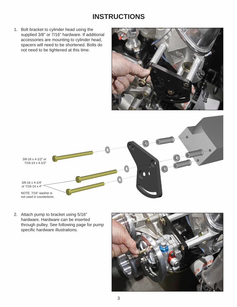
3/8-16 x 3-1/2”
3/8-16 x 4-1/4”
3/8-16 x 4-1/4”
PARTS LISTTCP PBS-FD-03 - Power Steering Pump Bracket Set - Ford FE
Qty Part Number Description1 7900-146 KRC Pump Bracket FE Ford Block 390-427-4281 7918-010 Hardware Bag for TCP PBS-FD-031 7918-012 Spacer Set Ford Power Steering Pump Bracket
7918-010 - Hardware BagQty Part Number Description2 3100-031C2.75Y Bolt 5/16-18 x 2-3/4" Hex Head Cap Screw2 3100-031C3.50Y Bolt 5/16-18 x 3-1/2" Hex Head Cap Screw1 3100-038C3.50Y Bolt 3/8-16 x 3-1/2" Hex Head Cap Screw2 3100-038C4.25Y Bolt 3/8-16 x 4-1/4" Hex Head Cap Screw1 3119-031-18C Flange Nut 5/16-18; 1/2 Hex2 3120-031S-Y Washer 5/16 Flat SAE .345 x .690 x .060 Thick3 3120-038S-Y Washer 3/8 Flat SAE .410 x .810 x .060 Thick
7918-012 - Hardware Bag, Spacer Set6 3109-044S1-S Aircraft Washer 7/16 Flat .453 x .750 x .032 Thick6 3109-044S2-S Aircraft Washer 7/16 Flat .453 x .750 x .063 Thick3 7900-170-0370 Spacer .453 ID x .370 Long x .75 OD with .850 Shoulder3 7900-170-2910 Spacer .453 ID x 2.910 Long x .75 OD with .850 Shoulder
PUMP BRACKET SET - TCP PBS-FD-03Ford FE Block 390, 427 & 428
INSTRUCTIONS1. Bolt bracket to cylinder head using the supplied 3/8” hardware. The spacer for the water pump bolt will
need to be cut for a correct fi t due to variations in castings from different manufacturers.a. The correct length for a stock water pump application is 1-5/8”, your application may vary. Cut should be made to narrow end of spacer and must be square.
2. Follow procedures described in TCP PBS-FD-01 instructions (Page 2).

8
TCP PBS-UNIVPump Bracket Set Universal
DESCRIPTION:Pump bracket set universal - includes; 6x6 square billet aluminum bracket with pump mounting holes, spacer & hardware. Attaches power steering pump to applications on which a direct bolt-on bracket is not available. Customer must machine to fi t.
PARTS LISTTCP PBS-UNIV - Power Steering Pump Bracket Set - Universal
Qty Part Number Description1 7900-150 Mounting Bracket Universal, 6 x 61 7918-012 Spacer Set Ford Power Steering Pump Bracket
7918-068 - Hardware BagQty Part Number Description2 3100-031C2.75Y Bolt 5/16-18 x 2-3/4” Hex Head Cap Screw2 3100-031C3.50Y Bolt 5/16-18 x 3-1/2” Hex Head Cap Screw1 3119-031-18C Flange Nut 5/16-182 3120-031S-Y Washer 5/16 Flat SAE .345 x .690 x .060 Thick
7918-012 - Hardware Bag, Spacer Set6 3109-044S1-S Aircraft Washer 7/16 Flat .453 x .750 x .032 Thick6 3109-044S2-S Aircraft Washer 7/16 Flat .453 x .750 x .063 Thick3 7900-170-0370 Spacer .453 ID x .370 Long x .75 OD with .850 Shoulder3 7900-170-2910 Spacer .453 ID x 2.910 Long x .75 OD with .850 Shoulder
9
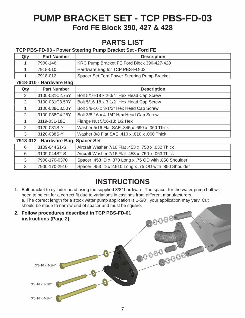
INFORMATION• We recommend securing the bracket to vehicle with a minimum of three mounting bolts.• Determine a bolt pattern based upon available mounting locations.• Check for adequate pump and hose clearance when choosing a location.• Some bolts may need to be positioned underneath the mounting surface of the pump. A counter bore is
required in these situations. Counter bore depth should not exceed .375”
1. Spacers will need to be modifi ed to fi t your particular application.a) Use a straight edge along face of pulleys to measure correct amount to shorten spacers.
2. Shims are included for use between aluminum spacers as required.3. Bracket must be oriented so that opening for fl ange nut is on opposite side of bracket from pump.
a) Flanged end of nut will be closest to pump.b) Refer to illustration to right.
4. Orient slot so that pump can be rotated away from driving pulley to allow greatest range of adjustment.5. The pump will pivot on the upper bolt and should be installed ‘fi nger-tight’ until belt
has been tensioned. Refer to page 4 of this instruction guide for pump specifi c hardware.
6. Lower bolt goes into fl ange nut and is tightened while holding tension on belt.a) Torque bolt to 12-18 lb. ft.
7. Upper bolt can now be tightened.a) Torque bolt to 12-18 lb. ft.
8. See Hose Kit instructions for hose assembly, routing and hook-up.
Bracket Mounting ExampleNote that the aluminum spacers are trimmed to different lengths as needed.

10
TCP HOSE-01Blue Fabric Covered Hose Kit, Remote Reservoir (Street or Pro Pump)
DESCRIPTION:TCP hose kit OEM style. Contains -6 & -10 cloth exterior bulk hose lengths and required zinc plated steel hose ends to connect power rack & pinion, power steering pump and remote reservoir.
APPLICATIONS:Fits applications using TCP power rack & pinion with power steering pump and remote reservoir.
WARNING: Use ONLY petroleum based power steering fl uid with this product. Use of ATF or synthetic fl uids will result in damage to the internal seals.
PARTS LISTTCP HOSE-01 - Blue Fabric Covered Hose Kit, Remote Reservoir (Street or Pro Pump)
Qty Part Number Description1 7900-160 Hose, -6 High Pressure 2250 psi; 84” Long Blue Cloth 1 7900-161 Hose, -10 High Pressure 1750 psi; 36” Long Blue Cloth4 7900-162 Hose End, 90 deg. -6 AN/JIC 37 deg. Flare Steel (AQP1389)2 7900-163 Hose End, 90 deg. -10 AN/JIC 37 deg. Flare Steel (AQP1374)
INSTRUCTIONS1. Instructions for mounting the bracket and pump are provided in the applicable TCP PBS-XX kit.2. Reservoir must be mounted in close proximity to the pump (i.e. inner fender,
radiator support, shock tower).a. When fi lled, fl uid level of reservoir must be 2 or more inches above top of pump.b. Do not mount near exhaust headers or sources of extreme heat.
3. Route hoses away from headers and moving parts.a. Leave slack in hoses to allow for engine movement and pressure changes. Avoid tight bends.b. Determine correct length, and then mark hose using tape.
4. Cut hoses square with fi ne-tooth hacksaw or cut-off wheel. (Fig. 1-1)

11
5. Clean inside of hoses thoroughly. Small metal and rubber particles will lock up the pump.a. Use a rifl e bore brush to remove loose particles in the hoses.b. Flush hoses with hot water and use compressed air to dry before use.
6. Disassemble the hose ends and place the outer socket into a vise to thread the hose into the socket. (Fig. 1-2)a. The socket uses left-handed threads so the hose will be turned counter-clockwise.b. Turn until hose bottoms in socket then back off 1/4 turn.
7. Lubricate the tapered threaded end of hose and inside of hose. (Fig. 1-3)a. Power steering fl uid can be used.
8. Screw hose end into socket and hose. (Fig. 1-4)a. Leave a 1/32” to 1/16” clearance between hose end hex and socket.
9. Route hoses as intended in step 3 avoiding exhaust headers and moving parts.a. Leave slack in hoses to allow for engine movement and pressure changes. Avoid tight bends.b. Secure hoses where necessary to maintain safe clearance from extreme heat and moving parts.
10. Connect -10 hose to bottom of reservoir and to red fi tting at pump.11. Connect -6 hose to blue/black fi tting of pump and to rack-&-pinion control servo
fi tting marked “P” (pump).12. Connect -6 hose to rack-&-pinion control servo fi tting marked “T” (tank/
reservoir) and to side of reservoir.13. Fill system with clear, petroleum based power steering fl uid.
a. Do not use ATF or synthetic fl uid.14. Raise front wheels off ground.15. Turn steering lock to lock repeatedly while maintaining fl uid level in reservoir to
completely fi ll the system.16. Start engine and turn steering lock to lock repeatedly to bleed air
from system.17. Lower front wheels.18. Check fl uid level and system for any leaks.
TIPS TO EXTEND THE LIFE OF YOUR PUMP• Use clear, high-temperature, petroleum based, power steering fl uid
and change it on a regular basis.• Fluid level must be two or more inches higher than top of pump.• When assembling new hoses, clean them with a rifl e bore brush
and then fl ush them out with hot water and air dry before use. Most problems with power steering systems are due to contamination from new hoses or other steering components which in turn damage the pump. Always place caps on pumps, rack fi ttings, and hoses when system is open to the air.
• Never start your engine without fl uid in the reservoir tank. One minute without fl uid can damage the pump.
• Route all hoses and reservoir tanks away from headers to keep from adding heat to the system and burning the fl uid.• Do no install any fi lters or coolers on the -10 side of the reservoir. Install them on the -6, return sides if they are needed.
12
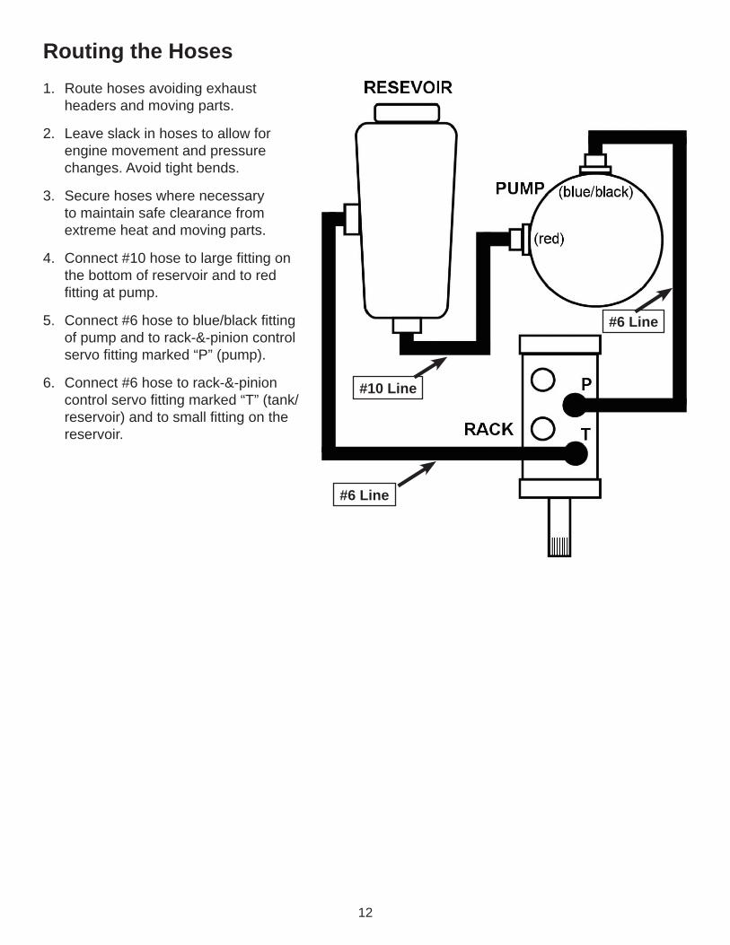
1. Route hoses avoiding exhaust headers and moving parts.
2. Leave slack in hoses to allow for engine movement and pressure changes. Avoid tight bends.
3. Secure hoses where necessary to maintain safe clearance from extreme heat and moving parts.
4. Connect #10 hose to large fi tting on the bottom of reservoir and to red fi tting at pump.
5. Connect #6 hose to blue/black fi tting of pump and to rack-&-pinion control servo fi tting marked “P” (pump).
6. Connect #6 hose to rack-&-pinion control servo fi tting marked “T” (tank/reservoir) and to small fi tting on the reservoir.
#10 Line
#6 Line
#6 Line
Routing the Hoses

13
Maximum Pump SpeedThe maximum recommended pump speed is 9,000 rpm. Street performance engines with commonly sized crankshaft pulleys will rotate the power steering pump well below the 9,000 rpm limit. Customers with high-rpm engines or engines with over-driven pulley arrangements must calculate the pump speed to ensure they are not exceeding the pump’s maximum speed.
Calculating Pump SpeedDivide your crank pulley diameter by the power steering pump pulley diameter and multiply by maximum engine rpm.
(Example: 5.5” crank pulley ÷ 6” pump pulley = 0.916 x 6,500 engine rpm = 5,958 rpm pump speed.)
Slowing Down the PumpIf a smaller crank pulley is not an option, larger diameter pump pulleys are available special order for extremely high-rpm engine applications to signifi cantly slow the pump speed. This option reduces low speed pump output and should not be used for street cars. (Correct torque on the pump pulley nut is 46 ft-lbs.)
1. Before fi lling the system with fl uid remove the power steering belt from the pump.
2. Fill system with clear, petroleum based power steering fl uid. Do not use ATF or synthetic fl uid.
3. As the system is being fi lled, the pump must be rotated several times by hand to prime the pump. Leave the cap off of the reservoir to monitor the fl uid level. Fluid must be added to prevent the pump from drawing in air.
IMPORTANT: Failure to properly prime the pump before starting the engine for the fi rst time after installation will damage the pump. Pumps that are damaged are not covered by any type of warranty and the customer will be responsible for replacement costs.
4. Raise the front wheels off the ground, then start the engine and turn the steering lock to lock repeatedly to work any air out of the system while maintaining the fl uid level in the reservoir to completely fi ll the system.
5. The reservoir should be fi lled to approximately the halfway point between the top of the internal turn tube and the top of the reservoir.
Remove the Belt
Filling the Reservoir
14
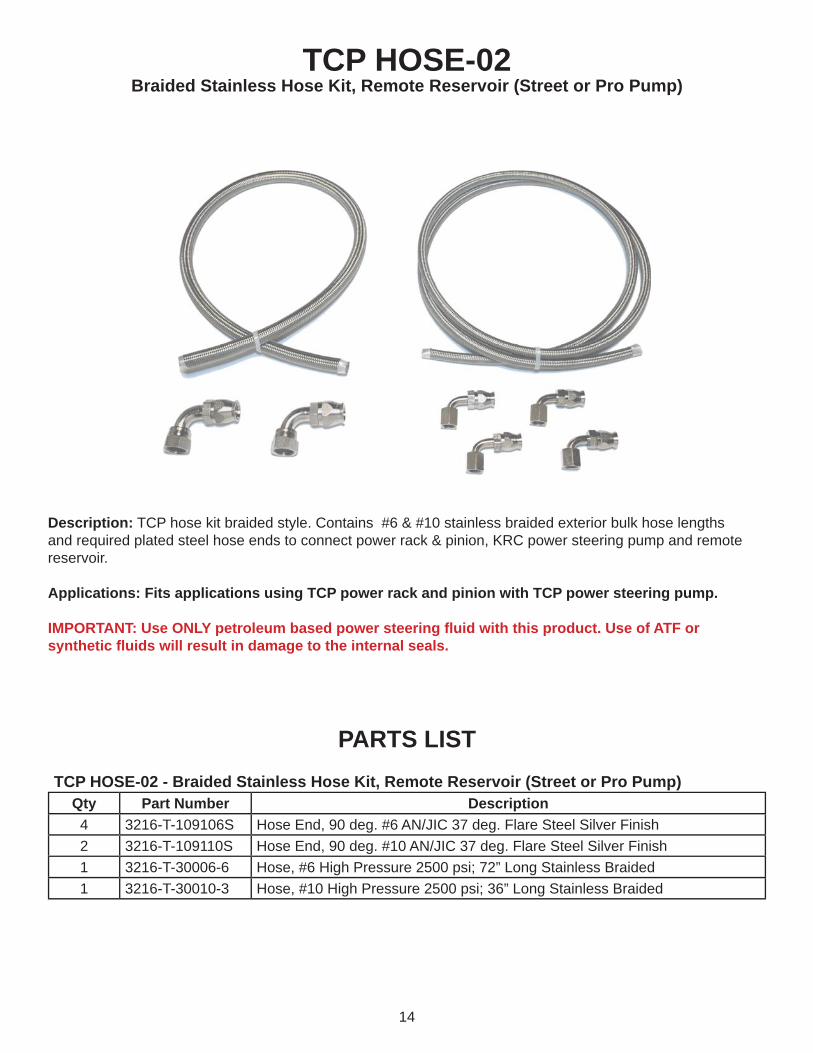
TCP HOSE-02Braided Stainless Hose Kit, Remote Reservoir (Street or Pro Pump)
Description: TCP hose kit braided style. Contains #6 & #10 stainless braided exterior bulk hose lengths and required plated steel hose ends to connect power rack & pinion, KRC power steering pump and remote reservoir.
Applications: Fits applications using TCP power rack and pinion with TCP power steering pump.
IMPORTANT: Use ONLY petroleum based power steering fl uid with this product. Use of ATF or synthetic fl uids will result in damage to the internal seals.
PARTS LISTTCP HOSE-02 - Braided Stainless Hose Kit, Remote Reservoir (Street or Pro Pump)
Qty Part Number Description4 3216-T-109106S Hose End, 90 deg. #6 AN/JIC 37 deg. Flare Steel Silver Finish2 3216-T-109110S Hose End, 90 deg. #10 AN/JIC 37 deg. Flare Steel Silver Finish1 3216-T-30006-6 Hose, #6 High Pressure 2500 psi; 72” Long Stainless Braided 1 3216-T-30010-3 Hose, #10 High Pressure 2500 psi; 36” Long Stainless Braided

15
Installing the Reservoir1. The reservoir must be mounted in
close proximity to the pump (i.e. inner fender, radiator support, or shock tower).
2. The hidden plug inside the billet clamp pushes against the reservoir body so the clamp can be tightened anywhere along the length of the reservoir.
3. Slide the clamp assembly over the reservoir and tighten the allen head cap screws from the back side of the clamp. Test fi t the reservoir to make sure the fi ttings are correctly clocked and easily accessible before fully tightening the clamp.
INSTRUCTIONS
4. Next attach the 14 degree adapter, TCP PSR-01, to the billet clamp assembly with the socket-head cap screws provided.
16
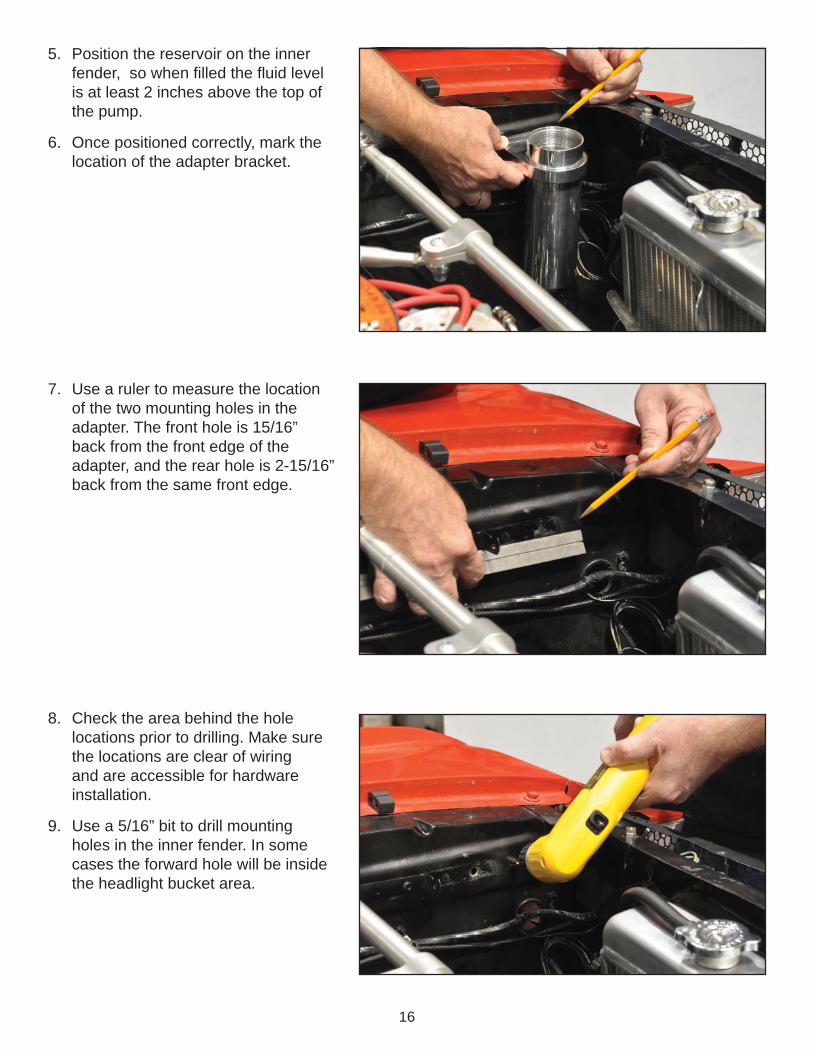
5. Position the reservoir on the inner fender, so when fi lled the fl uid level is at least 2 inches above the top of the pump.
6. Once positioned correctly, mark the location of the adapter bracket.
7. Use a ruler to measure the location of the two mounting holes in the adapter. The front hole is 15/16” back from the front edge of the adapter, and the rear hole is 2-15/16” back from the same front edge.
8. Check the area behind the hole locations prior to drilling. Make sure the locations are clear of wiring and are accessible for hardware installation.
9. Use a 5/16” bit to drill mounting holes in the inner fender. In some cases the forward hole will be inside the headlight bucket area.

17
10. Secure the reservoir to the inner fender with the 5/16-18 x 1/2” button heads and fl at washers supplied with the adapter.
11. The reservoir is now installed.
Assembling the Hoses12. If the end of the hose is frayed, it will
need to be taped and cut to have both ends of the hose straight and usable.
13. Wrap the hose with tape centered on the marked cut line.

18
14. Cut hoses square with fi ne-tooth hacksaw or cut-off wheel.
15. Burrs along the inside edge of the Tefl on hose can be removed with a razor.
16. Clean inside of hoses thoroughly. Small metal and Tefl on particles will damage the pump.
17. Use a rifl e bore brush, water, and compressed air to remove loose particles and dry each hose.
18. Disassemble the hose ends and slide the outer socket onto the hose with the threaded end of socket closest to the freshly cut end of the hose.
19
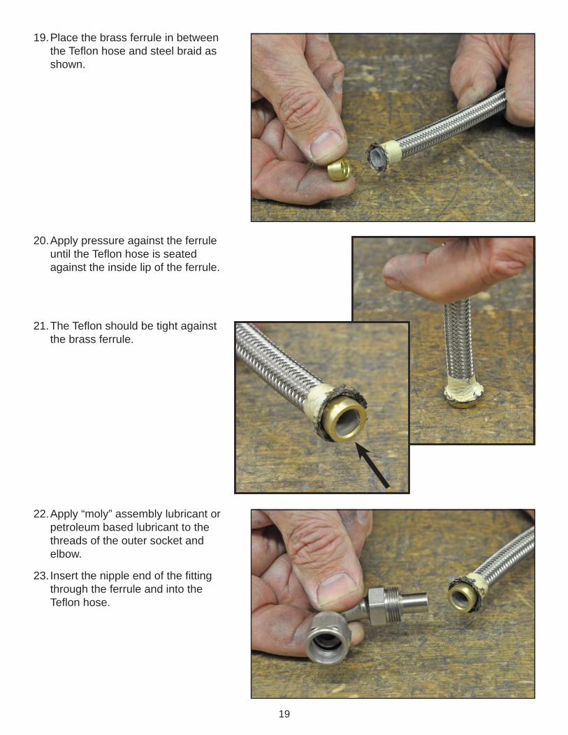
19. Place the brass ferrule in between the Tefl on hose and steel braid as shown.
20. Apply pressure against the ferrule until the Tefl on hose is seated against the inside lip of the ferrule.
21. The Tefl on should be tight against the brass ferrule.
22. Apply “moly” assembly lubricant or petroleum based lubricant to the threads of the outer socket and elbow.
23. Insert the nipple end of the fi tting through the ferrule and into the Tefl on hose.
20
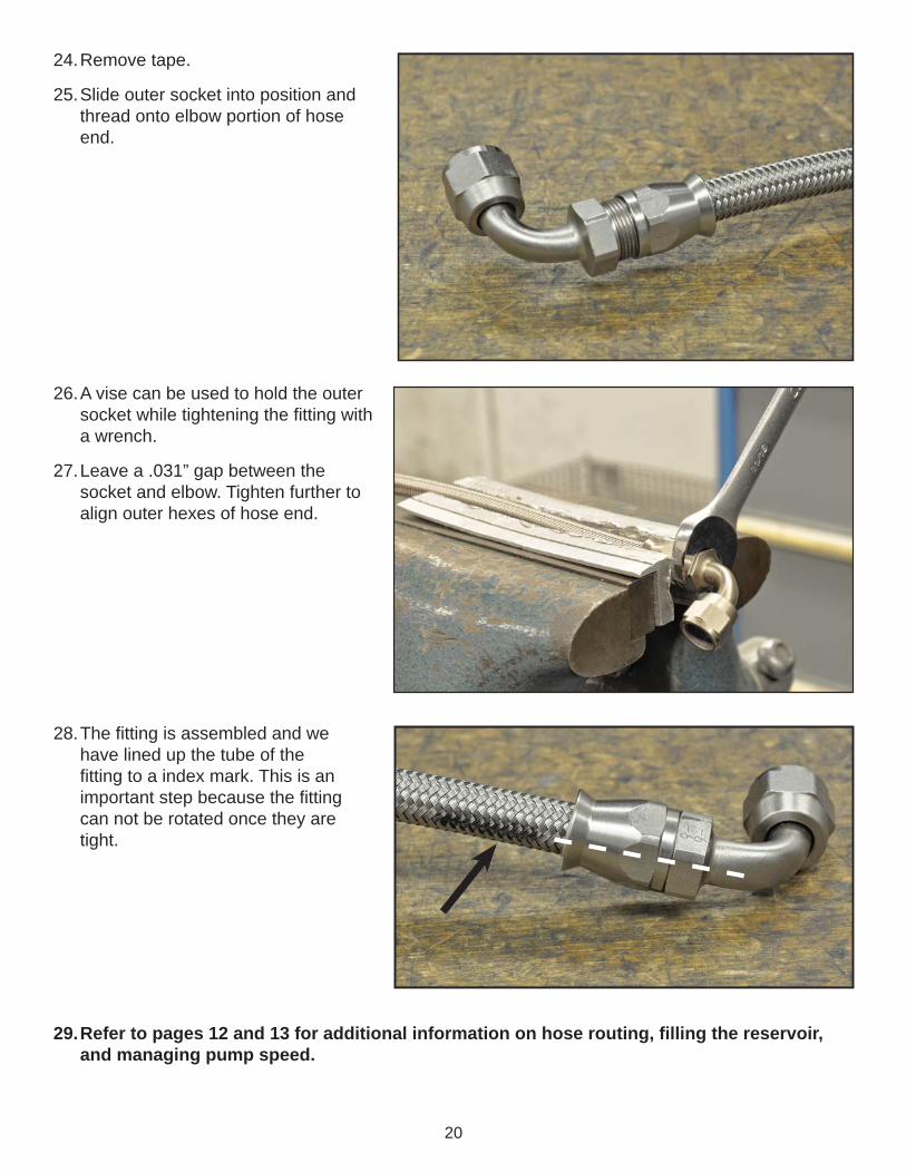
24. Remove tape.
25. Slide outer socket into position and thread onto elbow portion of hose end.
26. A vise can be used to hold the outer socket while tightening the fi tting with a wrench.
27. Leave a .031” gap between the socket and elbow. Tighten further to align outer hexes of hose end.
28. The fi tting is assembled and we have lined up the tube of the fi tting to a index mark. This is an important step because the fi tting can not be rotated once they are tight.
29. Refer to pages 12 and 13 for additional information on hose routing, fi lling the reservoir, and managing pump speed.
21
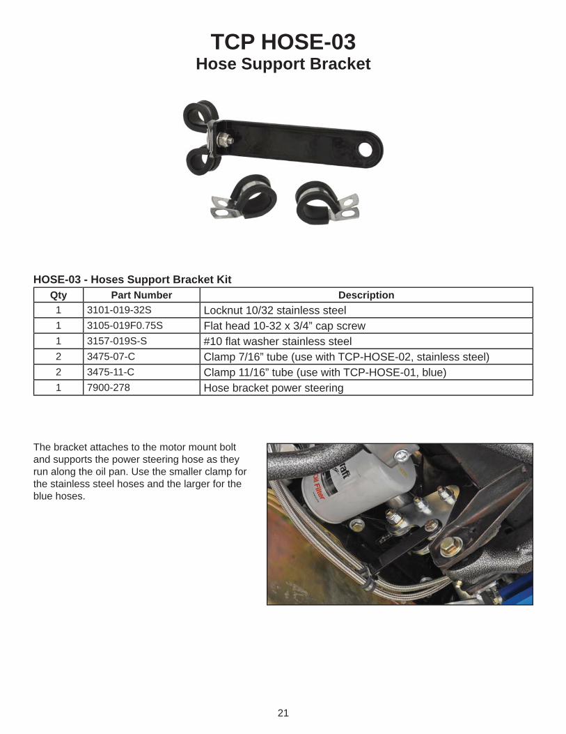
TCP HOSE-03Hose Support Bracket
HOSE-03 - Hoses Support Bracket KitQty Part Number Description1 3101-019-32S Locknut 10/32 stainless steel 1 3105-019F0.75S Flat head 10-32 x 3/4” cap screw1 3157-019S-S #10 fl at washer stainless steel2 3475-07-C Clamp 7/16” tube (use with TCP-HOSE-02, stainless steel)2 3475-11-C Clamp 11/16” tube (use with TCP-HOSE-01, blue)1 7900-278 Hose bracket power steering
The bracket attaches to the motor mount bolt and supports the power steering hose as they run along the oil pan. Use the smaller clamp for the stainless steel hoses and the larger for the blue hoses.

22
TCP HOSE-04Braided Stainless Hose Kit, Integral Reservoir (Pro Pump)
Description: TCP hose kit braided style. Contains #6 stainless braided exterior bulk hose lengths and required plated steel hose ends to connect power rack & pinion and integral reservoir power steering pump.
Applications: Fits applications using TCP power rack and pinion with TCP power steering pump.
IMPORTANT: Use ONLY petroleum based power steering fl uid with this product. Use of ATF or synthetic fl uids will result in damage to the internal seals.
INSTRUCTIONS1. Refer to TCP HOSE-02, beginning on page 14, for hose assembly instructions.2. Refer to pages 12 and 13 for additional information on hose routing, fi lling the reservoir, and managing
pump speed.
PARTS LISTTCP HOSE-04 - Braided Stainless Hose Kit, Integral Reservoir (Pro Pump)
Qty Part Number Description4 3216-T-109106S Hose End, 90 deg. #6 AN/JIC 37 deg. Flare Steel Silver Finish1 3216-T-30006-6 Hose, #6 High Pressure 2500 psi; 72” Long Stainless Braided
23
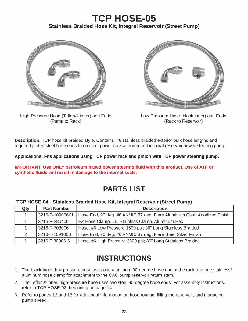
TCP HOSE-05Stainless Braided Hose Kit, Integral Reservoir (Street Pump)
Description: TCP hose kit braided style. Contains #6 stainless braided exterior bulk hose lengths and required plated steel hose ends to connect power rack & pinion and integral reservoir power steering pump.
Applications: Fits applications using TCP power rack and pinion with TCP power steering pump.
IMPORTANT: Use ONLY petroleum based power steering fl uid with this product. Use of ATF or synthetic fl uids will result in damage to the internal seals.
INSTRUCTIONS1. The black-inner, low-pressure hose uses one aluminum 90-degree hose end at the rack and one stainless/
aluminum hose clamp for attachment to the CAC pump reservoir return stem.2. The Tefl on®-inner, high-pressure hose uses two steel 90-degree hose ends. For assembly instructions,
refer to TCP HOSE-02, beginning on page 14.3. Refer to pages 12 and 13 for additional information on hose routing, fi lling the reservoir, and managing
pump speed.
PARTS LISTTCP HOSE-04 - Stainless Braided Hose Kit, Integral Reservoir (Street Pump)
Qty Part Number Description1 3216-F-109006CL Hose End, 90 deg. #6 AN/JIC 37 deg. Flare Aluminum Clear Anodized Finish1 3216-F-280406 EZ Hose Clamp, #6, Stainless Clamp, Aluminum Hex1 3216-F-703006 Hose, #6 Low Pressure 1500 psi; 36” Long Stainless Braided2 3216-T-109106S Hose End, 90 deg. #6 AN/JIC 37 deg. Flare Steel Silver Finish1 3216-T-30006-6 Hose, #6 High Pressure 2500 psi; 36” Long Stainless Braided
High-Pressure Hose (Tefl on®-inner) and Ends (Pump to Rack)
Low-Pressure Hose (black-inner) and Ends (Rack to Reservoir)

24
WARRANTY NOTICE:There are NO WARRANTIES, either expressed or implied. Neither the seller nor manufacturer will be liable for any loss, damage or injury, direct or indirect, arising from the use or inability to determine the appropriate use of any products. Before any attempt at installation, all drawings and/or instruction sheets should be completely reviewed to determine the suitability of the product for its intended use. In this connection, the user assumes all responsibility and risk. We reserve the right to change specifi cation without notice. Further, Chris Alston’s Chassisworks, Inc., makes NO GUARANTEE in reference to any specifi c class legality of any component. ALL PRODUCTS ARE INTENDED FOR RACING AND OFF-ROAD USE AND MAY NOT BE LEGALLY USED ON THE HIGHWAY. The products offered for sale are true race-car components and, in all cases, require some fabrication skill. NO PRODUCT OR SERVICE IS DESIGNED OR INTENDED TO PREVENT INJURY OR DEATH.
Total Control ProductsA Chris Alston’s Chassisworks, Inc. Brand8661 Younger Creek DriveSacramento, CA 95828Phone: 916-388-0288Technical Support: [email protected]
7903-PSP-FD REV 11/09/15
ChassisworksChassisworksCHRIS ALSTON'SCHRIS ALSTON'S
T H E H O M E O F H I G H E R T E C H N O L O G YT H E H O M E O F H I G H E R T E C H N O L O G Y