Embed Size (px)
Citation preview
H-59
(A) Photoelectric Sensors
(B) FiberOpticSensors
(C) Door/AreaSensors
(D) ProximitySensors
(E) PressureSensors
(F) RotaryEncoders
(G) Connectors/Connector Cables/Sensor DistributionBoxes/Sockets
(H)TemperatureControllers
(I)SSRs / PowerControllers
(J) Counters
(K) Timers
(L) PanelMeters
(M)Tacho /Speed / PulseMeters
(N)DisplayUnits
(O)SensorControllers
(P)SwitchingMode PowerSupplies
(Q)Stepper Motors & Drivers & Controllers
(R)Graphic/LogicPanels
(S)FieldNetworkDevices
(T) Software
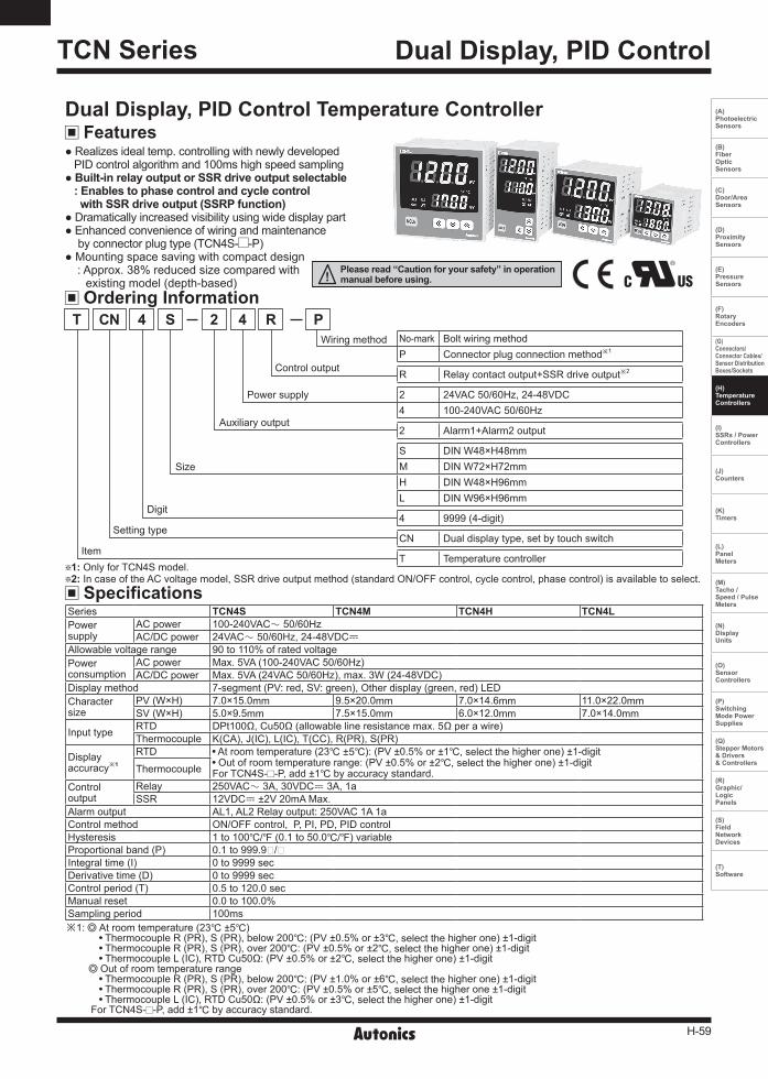
Dual Display, PID ControlTCN Series
FeaturesDual Display, PID Control Temperature Controller
Realizesidealtemp.controllingwithnewlydevelopedPIDcontrolalgorithmand100mshighspeedsamplingBuilt-in relay output or SSR drive output selectable : Enables to phase control and cycle control with SSR drive output (SSRP function)DramaticallyincreasedvisibilityusingwidedisplaypartEnhancedconvenienceofwiringandmaintenancebyconnectorplugtype(TCN4S- -P)
Mountingspacesavingwithcompactdesign:Approx.38%reducedsizecomparedwithexistingmodel(depth-based)
Ordering Information
SpecificationsSeries TCN4S TCN4M TCN4H TCN4L Powersupply
ACpower 100-240VACᜠ50/60HzAC/DCpower 24VACᜠ50/60Hz,24-48VDCᜡ
Allowablevoltagerange 90to110%ofratedvoltagePowerconsumption
ACpower Max.5VA(100-240VAC50/60Hz)AC/DCpower Max.5VA(24VAC50/60Hz),max.3W(24-48VDC)
Displaymethod 7-segment(PV:red,SV:green),Otherdisplay(green,red)LEDCharactersize
PV(W×H) 7.0×15.0mm 9.5×20.0mm 7.0×14.6mm 11.0×22.0mmSV(W×H) 5.0×9.5mm 7.5×15.0mm 6.0×12.0mm 7.0×14.0mm
Inputtype RTD DPt100Ω,Cu50Ω(allowablelineresistancemax.5Ωperawire)Thermocouple K(CA),J(IC),L(IC),T(CC),R(PR),S(PR)
Displayaccuracy※1
RTD Atroomtemperature(23 ±5):(PV±0.5%or±1, select the higherone)±1-digitOutofroomtemperaturerange:(PV±0.5%or±2, select the higherone)±1-digitForTCN4S- -P,add±1byaccuracystandard.Thermocouple
Controloutput
Relay 250VACᜠ3A,30VDCᜡ3A,1aSSR 12VDCᜡ±2V20mAMax.
Alarmoutput AL1,AL2Relayoutput:250VAC1A1aControlmethod ON/OFFcontrol,P,PI,PD,PIDcontrolHysteresis 1to100/ (0.1to50.0/)variableProportionalband(P) 0.1to999.9/Integraltime(I) 0to9999secDerivativetime(D) 0to9999secControlperiod(T) 0.5to120.0secManualreset 0.0to100.0%Samplingperiod 100ms※1: Atroomtemperature(23±5)
ThermocoupleR(PR),S(PR),below200: (PV±0.5%or±3, select the higherone)±1-digitThermocoupleR(PR),S(PR),over200:(PV±0.5%or±2, select the higherone)±1-digitThermocoupleL(IC),RTDCu50Ω:(PV±0.5%or±2, select the higherone)±1-digit
OutofroomtemperaturerangeThermocoupleR(PR),S(PR),below200: (PV±1.0%or±6, select the higherone)±1-digitThermocoupleR(PR),S(PR),over200:(PV±0.5%or±5, select the higherone±1-digitThermocoupleL(IC),RTDCu50Ω:(PV±0.5%or±3, select the higherone)±1-digit
ForTCN4S- -P,add±1byaccuracystandard.
Settingtype
Item
Digit
Size
Auxiliaryoutput
Powersupply
Controloutput
Wiringmethod No-mark BoltwiringmethodP Connectorplugconnectionmethod※1
R Relaycontactoutput+SSRdriveoutput※2
2 24VAC50/60Hz,24-48VDC4 100-240VAC50/60Hz
2 Alarm1+Alarm2output
S DINW48×H48mmM DINW72×H72mmH DINW48×H96mmL DINW96×H96mm
4 9999(4-digit)
CN Dualdisplaytype,setbytouchswitch
T Temperaturecontroller
CNT S 2 P4 R4
1: OnlyforTCN4Smodel. 2:IncaseoftheACvoltagemodel,SSRdriveoutputmethod(standardON/OFFcontrol,cyclecontrol,phasecontrol)isavailabletoselect.

H-60
TCN Series
Specifications
Connections
TCN4S
TCN4M
※ TCN4Serieshasselectablecontroloutput;Relayoutput,andSSRdriveoutput.AC/DCvoltagetypedoesnothaveSSRPfunction.
※2: Theweightincludespackaging.Theweightinparenthesisisforunitonly.※Environmentresistanceisratedatnofreezingorcondensation.
※1:PowersupplyACpower:100-240VAC5VA50/60HzAC/DCpower:24VAC5VA50/60Hz,24-48VDC3W
Series TCN4S TCN4M TCN4H TCN4L Dielectricstrength
ACPower 2,000VAC50/60Hzfor1min(betweeninputterminalandpowerterminal)AC/DCpower 1,000VAC50/60Hzfor1min(betweeninputterminalandpowerterminal)
Vibration 0.75mmamplitudeatfrequencyof5to55HzineachX,Y,Zdirectionfor2hours
Relaylifecycle
Mechanical OUT:over5,000,000times,AL1/2:Over5,000,000times
Electrical OUT:over200,000times(250VAC3Aresistiveload)AL1/2:over300,000times(250VAC1Aresistiveload)
Insulationresistance Over100MΩ(at500VDCmegger)Noiseimmunity ±2kVR-phase,S-phasethesquarewavenoise(pulsewidth:1us)bythenoisesimulatorMemoryretention Approx.10years(whenusingnon-volatilesemiconductormemorytype)
Environ-ment
Ambienttemperature -10to50,storage:-20to60Ambienthumidity 35to85%RH,storage:35to85%RH
Insulationtype Double insulationorreinforced insulation(mark: ,dielectricstrengthbetweenthemeasuring inputpartandthepowerpart:ACpower2kV,AC/DCPower1kV)
Approval
Weight※2 Approx.147g(approx.100g)
Approx.203g(approx.133g)
Approx.194g(approx.124g)
Approx.275g(approx.179g)
13
19
14
20
15
21
16
22
17
23
18
24
SSROUT:12VDC±2V20Max.
※1SOURCE:100-240VAC5VA50/60,24VAC5VA50/60,24-48VDC3W
B' RTD TC
SENSOR
AL1OUT:250VAC1A1a
AL2OUT:250VAC1A1a
RelayOUT:250VAC3A1a30VDC3A1a
B
A
1
7
2
8
3
9
4
10
5
11
6
12
1 7
2 8
3 94 10
5 116 12
SSROUT:12VDC±2V20mAMax. SSROUT:
12VDC±2V20mAMax.
※1 ※1SOURCE:100-240VAC5VA50/60,24VAC5VA50/60,24-48VDC3W
SOURCE:100-240VAC5VA50/60,24VAC5VA50/60,24-48VDC3W
B' RTD TC
SENSOR
AL1OUT:250VAC1A1a
AL2OUT:250VAC1A1a
RelayOUT:250VAC3A1a30VDC3A1a
B
A
TCN4H/L1
7
2
8
3
9
4
5
6
10
11
12
13
14
15
16
17
18
SSROUT:12VDC±2V20Max.
※1
SOURCE:100-240VAC5VA50/60,24VAC5VA50/60,24-48VDC3W
B' RTD TC
SENSOR
AL1OUT:250VAC1A1a
AL2OUT:250VAC1A1a
RelayOUT:250VAC3A1a30VDC3A1a
B
A
TCN4S- -PAL1OUT250VAC1A1aAL2OUT250VAC1A1a
B'
RTD
B
A
RelayOUT250VAC3A1a30VDC3A1a
TC
<Crimpterminal>
a
bc
Terminalnumber a b c1to8 6 Max.1.7 Max.3.79to11 6to8 Max.2.1 Max.4.212to14 6to8 Max.1.5 Max.3.5
(unit:mm)※Usecrimpterminalsorteminalsofsizespecifiedbelow.
a b
<Round>
a b
<Forked>a Min.3.0 Min.3.0b Max.5.8 Max.5.8

H-61
Dual Display, PID Control
(A) Photoelectric Sensors
(B) FiberOpticSensors
(C) Door/AreaSensors
(D) ProximitySensors
(E) PressureSensors
(F) RotaryEncoders
(G) Connectors/Connector Cables/Sensor DistributionBoxes/Sockets
(H)TemperatureControllers
(I)SSRs / PowerControllers
(J) Counters
(K) Timers
(L) PanelMeters
(M)Tacho /Speed / PulseMeters
(N)DisplayUnits
(O)SensorControllers
(P)SwitchingMode PowerSupplies
(Q)Stepper Motors & Drivers & Controllers
(R)Graphic/LogicPanels
(S)FieldNetworkDevices
(T) Software
Dimensions (unit:mm)
TCN4S
TCN4M
TCN4L
Bracket
45
64.5648 TCN4S- -P
48
44.8
561.7
11.56
64.5
67.5
672 TCN4H
96
48
91.5
64.56
91.5
64.5696
TCN4SSeries TCN4M,TCN4H,TCN4LSeries
46
23.9
12
37.5
40.5
3.3
4 Panel cut-out
SizeSeries
A B C D
TCN4S Min.65 Min.65 45 0.60 45 0.6
0
TCN4M Min.90 Min.90 68 0.70 68 0.7
0
TCN4H Min.65 Min.115 45 0.60 92 0.8
0
TCN4L Min.115 Min.115 92 0.80 92 0.8
0
A
C
D
B
31
55
56
20
1521
545
16
48.6
44.9 36

H-62
TCN Series
4. Auto tuning indicator: ATindicatorflashesbyevery1secduringoperatingautotuning.5. key:Usedwhenenteringintoparametersettinggroup,returningtoRUNmode,movingparameter,andsavingsettingvalues.
6. Adjustment: Usedwhenenteringintosetvaluechangemode,digitmovinganddigitup/down.7. Digital input key:Press + keysfor3sectooperatethesetfunction(RUN/STOP,alarmoutputreset,autotuning)indigitalinputkey[DI-K].
8. Temperature unit (/) indicator:Itshowscurrenttemperatureunit.
Unit Description
SV Setting
Parameter Reset
1
2345 6
7
8
Youcansetthetemperaturetocontrolwith keys.SettingrangeiswithinSVlowerlimitvalue[L-SV]toSVhigherlimitvalue[H-SV].E.g.)Incaseofchangingsettemperaturefrom210ºCto250ºC
1. Present temperature (PV) display (red) RUNmode:Presenttemperature(PV)display. Parametersettingmode:Parameterdisplay.
2. Set temperature (SV) display (green) RUNmode:Settemperature(SV)display. Parametersettingmode:Parametersettingvaluedisplay.
3. Control/Alarm output display indicator OUT:ItturnsONwhenthecontroloutputisON. ※DuringSSRdriveoutputtypeinCYCLE/PHASEcontrol,thisindicator
turnsONwhenMVisover3.0%.(onlyACvoltagetype) AL1/AL2:ItturnsONwhenthealarmoutputisON.
Terminal cover (sold separately)
Dimensions (unit:mm)
RSA-COVER(48×48mm)
RMA-COVER(72×72mm)
RHA-COVER(48×96mm)
RLA-COVER(96×96mm)
70
68.5
3
64
13
91.5
86
4
13
47.2
91.5
86
3
13
9448.4
9.8
41.5
18 22
22.5
ChangeSVby , , keys
Pressanykeyamong , , , once.
①RUNmode
②SVsettingmode ③CompletesSVsetting
④CheckSV
Resetallparametersasfactorydefault.Holdthefront + + keysfor5sec,toenterparameterreset[INIT]parameter.Select'YES'andallparametersareresetasfactorydefault.Select‘NO’andprevioussettingsaremaintained.Ifsettingparameterlock[LOC]orprocessingauto-tuning,parameterresetisunavailable.

H-63
Dual Display, PID Control
(A) Photoelectric Sensors
(B) FiberOpticSensors
(C) Door/AreaSensors
(D) ProximitySensors
(E) PressureSensors
(F) RotaryEncoders
(G) Connectors/Connector Cables/Sensor DistributionBoxes/Sockets
(H)TemperatureControllers
(I)SSRs / PowerControllers
(J) Counters
(K) Timers
(L) PanelMeters
(M)Tacho /Speed / PulseMeters
(N)DisplayUnits
(O)SensorControllers
(P)SwitchingMode PowerSupplies
(Q)Stepper Motors & Drivers & Controllers
(R)Graphic/LogicPanels
(S)FieldNetworkDevices
(T) Software
Parameter Group
※Press keyover3secinanysettinggroup,itsavesthesetvalueandreturnstoRUNmode.(Press keyonceinSVsetting,itreturnstoRUNmode).※Ifnokeyenteredfor30sec,itreturnstoRUNmodeautomaticallyandthesetvalueofparameterisnotbesaved.※Press keyagainwithin1secafterreturningtoRUNmode,itadvancesofthefirstparameterofprevioussettinggroup.※Press keytomovenextparameter.※ Thisparametermightnotbedisplayeddependingonotherparametersettings.※ Setparameteras'Parametergroup2→Parametergroup1→Settingofsetvalue'orderconsideringparameterrelationofeachsettinggroup.
※1:ItisnotdisplayedforAC/DCpowermodel(TCN4 -22R).
Run mode
SV setting Parameter group 1 Parameter group 2
AL1alarmtemperature
AL2alarmtemperature
Inputsensor
Temperatureunit
Inputcorrection
Inputdigitalfilter
SVlow-limitvalue
SVhigh-limitvalue
ControloutputoperationControltype
Controloutputtype
SSRdriveoutputmethod※1
Controlcycle
AL1alarmoperationmode
AL2alarmoperationmode
Alarmoutputhysteresis
LBAmonitoringtime
LBAdetectionband
Digitalinputkey
ControloutputMVincaseof
inputbreakerrorParameter
lock
Autotuning
Proportionalband
Integraltime
Derivativetime
Manualreset
Hysteresis
Pressanykeyamong, , ,
PAR1
IN-Tㅑㅑ MAvF
PAR2
AL1 UNIT IN-Bㅑㅑ
L-SV H-SV O-FTC-MD
OUT SSrM T AL-1
AL-2AHYSLBaTLBaㅑㅑB
DI-K ErMV LOC
AL2
AT
P
I
D
REST
HYS
2sec
3sec 3sec
4sec

H-64
TCN Series
※1:S :Pressanykeyamong , , .※2:Aftercheckingorchangingsettingvalueineachparameter,press keytosave
andmovetonextparametersetting.※3:Itisdisplayedwhencontroltypeparameter[C-MD]ofparametergroup2isset PID.※Press keyfor3sectoreturnRUNmodeatanyparameter.※ Thisparametermightnotbedisplayeddependingonotherparametersettings.
Settingrange:Deviationalarm(-F.StoF.S),Absolutevaluealarm(temperaturerange)※ Incasealarmoperationmode[AL-2]ofParametergroup2isAM)_/SBa /BA ,noparametersisdisplayed.
Settingrange:0.1to999.9/
Settingrange:0to9999sec※IntegraloperationisOFFwhensetvalueis"0".
Settingrange:0to9999sec※DerivativeoperationisOFFwhensetvalueis"0".
Settingrange:0.0to100.0%※ItisdisplayedinP,PDcontrol.
Settingrange KCaH, JIcH,LIcH,TCcH,RPR,SRP,DPtH,CUsH:1to100/ KCaL, JIcL,LIcL,TCcL,DPtL,CUsL:0.1to50.0/※Itisdisplayedwhencontroltype[C-MD]ofparametergroup2issetONOF.
※FrontATindicatorflashesduringautotuningoperation.
Settingrange KCaH, JIcH,LIcH,TCcH,RPR,SRP,DPtH,CUsH:-999to999/ KCaL, JIcL,LIcL,TCcL,DPtL,CUsL:-199.9to999.9/
Settingrange:0.1to120.0sec※ Setinputdigitalfiltertimeforaverageinputvalueaffectedcontrol,anddisplayvalue.
※ Ifchangingtemperatureunit,SV, IN-B, H-SV, L-SV,AL1, AL2, LBaT, LBaB, AHYSparametervaluesareinitialized.
Settingrange:Referto'Inputsensorandtemperaturerange'.
※ Ifchanginginputsensor,SV, IN-B, H-SV, L-SV,AL1, AL2, LBaT, LBaB, AHYSparametervaluesareinitialized.
Parameter Group 1
Parameter Group 2
Settingrange:Deviationalarm(-F.StoF.S),Absolutevaluealarm(temperaturerange)※ Incasealarmoperationmode[AL-1]ofParametergroup2isAM)_/SBa /BA ,noparametersisdisplayed.
AL1alarmtemperature
AL2alarmtemperature
Auto-tuning
Proportionalband
Integraltime
Derivationtime
Manualreset
Hysteresis
Run mode
※3
PAR1
AL1
AL2
AT
P
I
D
REST
HYS
1250
1250
OFF ON
01)0
0000
0000
05)0
002
S
S
S
S
S
S
S
※1S
※2
2sec 3sec
Inputsensor
Temperatureunit
Inputcorrection
Inputdigitalfilter
PAR2
IN-T KCaH KCaL CUsL
UNIT ?C ?F
IN-B 0000
MAvF 00)1
※1S
S
S
S
※2
4sec
3sec
Run mode

H-65
Dual Display, PID Control
(A) Photoelectric Sensors
(B) FiberOpticSensors
(C) Door/AreaSensors
(D) ProximitySensors
(E) PressureSensors
(F) RotaryEncoders
(G) Connectors/Connector Cables/Sensor DistributionBoxes/Sockets
(H)TemperatureControllers
(I)SSRs / PowerControllers
(J) Counters
(K) Timers
(L) PanelMeters
(M)Tacho /Speed / PulseMeters
(N)DisplayUnits
(O)SensorControllers
(P)SwitchingMode PowerSupplies
(Q)Stepper Motors & Drivers & Controllers
(R)Graphic/LogicPanels
(S)FieldNetworkDevices
(T) Software
※Whenchangingcontroloutputoperation,ErMVisinitialized.
※ Whenchangingcontroltype,ErMVisinitialized(controloutputMVisbelow100%)andDI-T turnsOFFautomatically.
※Itisdisplayedwhenselectingcontroloutput[OUT]asSSR.ItisnotdisplayedforAC/DCpowermodel(TCN4 -22R).
Settingrange:0.5to120.0secIncaseofRelayoutput[RLY]ofcontroloutput[OUT]itissetas20.0secIncaseofSSRdriveoutput[SSR]ofthat,itissetas2.0sec※TisnotdisplayedwhenSSRdriveoutput[SSrM]methodissetasCYCL, PHAS.
Settingrange:0to9999sec※'0'isset,loopbreakalarmfunctionisOFF.※LBaTisdisplayedwhenAL1,AL2alarmoperationmode[AL-1,AL-2]issetasLBa.
Settingrange:0to999(0.0to999.9)/※'0'isset,loopbreakalarmfunctionisOFF.※ LBaBisdisplayedwhenAL1,AL2alarmoperationmode[AL-1,AL-2]issetasLBa andLBaTisnot'0'.
Settingrange:0.0to100.0%※Only0.0,100%aredisplayedwhencontroltype[C-MD]issetasONOF.※WhenchangingPIDcontroltoON/OFFcontrol,ifMVisbelow100.0%,itisinitializedas0.0%.
Settingrange:Withintheratedtemperaturerangebyinputsensor[L-SV ≤(H-SV-1-digit)]※ When changing SV low-limit value, if SV<L-SV, SV is initialized as L-SV.※ Incaseofchanginginputsensortype[IN-T],itchangesautomaticallyasmin.valueofthechangedinputsensor.
Settingrange:Withintheratedtemperaturerangebyinputsensor[H-SV ≥(L-SV+1-digit)]※ When changing SV high-limit value, if SV>H-SV, SV is initialized as H-SV.※ Incaseofchanginginputsensortype[IN-T],itchangesautomaticallyasmax.valueofthechangedinputsensor.
Formoredetailsreferto Functions' Alarm'.※Black:Flashes,Gray:Fixed※ WhenchangingAL1,AL2alarmoperationmode,AL1,AL2alarmtemperaturevalueareinitialized.
Press + keysfor3secanditexecutesthesetfunction.Formoreinformation,referto Functions' Digitalinputkey'.※Whencontroltype[C-MD]isONOF,ATisnotdisplayed.
LOC1:Locksparametergroup2LOC2:Locksparameter1,2groupLOC3:Locksparameter1,2groupandSVsetting※ Parametersettingvaluesarestillpossibletocheckwhenparameterlockisset.
Referto Functions' Alarmoutputhysteresis'.※ AHYSisnotdisplayedwhenAL1,AL2alarmoperationmode[AL-1,AL-2]issetasAM)_,SBa ,LBa .
SVlow-limitvalue
SVhigh-limitvalue
Controloutputoperation
Controltype
Controloutputtype
SSRdriveoutputmethod
Controlcycle
AL1alarmoperationmode
AL2alarmoperationmode
Alarmoutputhysteresis
LBAmonitoringtime
LBAdetectionband
Digitalinputkey
ControloutputMVincaseofinputbreakerror
Parameterlock
L-SV
H-SV
O-FT
C-MD
OUT
SSrM
AL-1
AL-2
DI-K
LBaB
LBaT
AHYS
T
ErMV
LOC
STND
AM!A
AM@A
STOP
0002
0000
001
02)0
AlRE AT OFF
00)0
OFF LOC1 LOC2 LOC3
CYCL PHAS
-050
1200
HEAT
PID
RLY
COOL
ONOF
SSR
S
S
S
S
S
S
S
S
S
S
S
S
S
S
S

H-66
TCN Series
Factory Default
Input Sensor and Temperature RangeInputsensor Display Temperaturerange() Temperaturerange()
Thermocouple
K(CA)KCaH -50to1200 -58to2192KCaL -50.0to999.9 -58.0to999.9
J(IC)JIcH -30to800 -22to1472JIcL -30.0to800.0 -22.0to999.9
L(IC)LIcH -40to800 -40to1472LIcL -40.0to800.0 -40to999.9
T(CC)TCcH -50to400 -58to752TCcL -50.0to400.0 -58.0to752.0
R(PR) R PR 0to1700 32to3092S(PR) S PR 0to1700 32to3092
RTDDPt100Ω
DPtH -100to400 -148to752DPtL -100.0to400.0 -148.0to752.0
Cu50ΩCUsH -50to200 -58to392CUsL -50.0to200.0 -58.0to392.0
Mounting TCN4S (48×48mm) Series Other Series
※Mounttheproductonthepanel,fastenbracketbypushingwithtoolsasshownabove.
Parameter group 1
Parameter group 2
SV setting
Parameter Factorydefault Parameter Factorydefault Parameter Factorydefault Parameter Factorydefault
IN-T KCaH H-SV 1200 T 02)0 LBaB 0002
UNIT ?C O-FT HEAT AL-1 AMiA DI-K STOP
IN-B 0000 C-MD PID LA-2 Am@A ErMV 00)0
MAvF 00)1 OUT RLY AHYS 001 LOC OFF
L-SV -050 SSrM STND LBaT 0000
Parameter Factorydefault Parameter Factorydefault Parameter Factorydefault Parameter Factorydefault
AL1 1250 AT OFF I 0000 REST 05)0
AL2 1250 P 01)0 D 0000 HYS 002
Parameter Factorydefault
- 0
※ TheAC/DCvoltagemodelsdonothaveSSRdriveoutputmethod[SSrM].Incaseofcontroloutput[OUT],ifsetas SSR,itsupportsonlyON/OFFoutput.

H-67
Dual Display, PID Control
(A) Photoelectric Sensors
(B) FiberOpticSensors
(C) Door/AreaSensors
(D) ProximitySensors
(E) PressureSensors
(F) RotaryEncoders
(G) Connectors/Connector Cables/Sensor DistributionBoxes/Sockets
(H)TemperatureControllers
(I)SSRs / PowerControllers
(J) Counters
(K) Timers
(L) PanelMeters
(M)Tacho /Speed / PulseMeters
(N)DisplayUnits
(O)SensorControllers
(P)SwitchingMode PowerSupplies
(Q)Stepper Motors & Drivers & Controllers
(R)Graphic/LogicPanels
(S)FieldNetworkDevices
(T) Software
Functions
Alarm operation
Alarm [AL-1 / AL-2]Alarm
operationAlarmoption
AM!A
Sensor break alarmThefunctionthatalarmoutputwillbeONwhensensorisnotconnectedorwhensensor'sdisconnectionisdetectedduringtemperaturecontrolling.Youcancheckwhetherthesensorisconnectedwithbuzzerorotherunitsusingalarmoutputcontact.Itisselectablebetweenstandardalarm[SBaA],oralarmlatch[SBaB].
Alarm optionMode Name DescriptionAM .A Standardalarm Ifitisanalarmcondition,alarmoutputisON.Ifitisaclearalarmcondition,alarmoutputisOFF.AM .B Alarmlatch Ifitisanalarmcondition,alarmoutputisONandmaintainsONstatus.
AM .C Standbysequence1Firstalarmconditionisignoredandfromsecondalarmcondition,standardalarmoperates.Whenpowerissuppliedanditisanalarmcondition,thisfirstalarmconditionisignoredandfromthesecondalarmcondition,standardalarmoperates.
AM .DAlarmlatchandstandbysequence1
Ifitisanalarmcondition,itoperatesbothalarmlatchandstandbysequence.Whenpowerissuppliedanditisanalarmcondition,thisfirstalarmconditionisignoredandfromthesecondalarmcondition,alarmlatchoperates.
AM .E Standbysequence2Firstalarmconditionisignoredandfromsecondalarmcondition,standardalarmoperates.Whenre-appliedstandbysequenceandifitisalarmcondition,alarmoutputdoesnotturnON.Afterclearingalarmcondition,standardalarmoperates.
AM .FAlarmlatchandstandbysequence2
Basicoperationissameasalarmlatchandstandbysequence1.ItoperatesnotonlybypowerON/OFF,butalsoalarmsettingvalue,oralarmoptionchanging.Whenre-appliedstandbysequenceandifitisalarmcondition,alarmoutputdoesnotturnON.Afterclearingalarmcondition,alarmlatchoperates.
Mode Name Alarmoperation Description
AM)_ - - Noalarmoutput
AM!
Deviationhigh-limitalarm
SV100
PV110
OFF ONH
PV90
SV100
OFF ONHIfdeviationbetweenPVandSVashigh-limitishigherthansetvalueofdeviationtemperature,thealarmoutputwillbeON.
Highdeviation:Setas10 Highdeviation:Setas-10
AM@
Deviationlow-limitalarm
PV90
SV100
OFFON H
SV100
PV110
OFFON HIfdeviationbetweenPVandSVaslow-limitishigherthansetvalueofdeviationtemperature,thealarmoutputwillbeON.
Lowerdeviation:Setas10 Lowerdeviation:Setas-10
AM#
Deviationhigh/low-limitalarm
PV90
PV110
SV100
OFFON ONH HIfdeviationbetweenPVandSVashigh/low-limitishigherthansetvalueofdeviationtemperature,thealarmoutputwillbeON.
High/Lowerdeviation:Setas10
AM$
Deviationhigh/low-limitreversealarm
PV90
PV110
SV100
OFFON ONH HIfdeviationbetweenPVandSVashigh/low-limitishigherthansetvalueofdeviationtemperature,thealarmoutputwillbeOFF.
High/Lowerdeviation:Setas10
AM%
Absolutevaluehighlimitalarm
PV90
SV100
OFF ONH
SV100
PV110
OFF ONH
IfPVishigherthantheabsolutevalue,theoutputwillbeON.
Absolute-valueAlarm:Setas90
Absolute-valueAlarm:Setas110
AM^
Absolutevaluelowlimitalarm
PV90
SV100
OFFON H
SV100
PV110
OFFON H
IfPVislowerthantheabsolutevalue,theoutputwillbeON.
Absolute-valueAlarm:Setas90
Absolute-valueAlarm:Setas110
SBa SensorbreakAlarm - ItwillbeONwhenitdetectssensordisconnection.LBa LoopbreakAlarm - ItwillbeONwhenitdetectsloopbreak.
※ H:Alarmoutputhysteresis[AHYS]
※Conditionofre-appliedstandbysequenceforstandbysequence1,alarmlatchandstandbysequence1:PowerONConditionofre-appliedstandbysequenceforstandbysequence2,alarmlatchandstandbysequence2:PowerON,changingsettemperature,alarmtemperature[AL1,AL2]oralarmoperation[AL-1,AL-2],switchingSTOPmodetoRUNmode.
Setbothalarmoperationandalarmoptionbycombining.Alarmoutputsaretwoandeachoneoperatesindividually.Whenthecurrenttemperatureisoutofalarmrange,alarmclearsautomatically.Ifalarmoptionisalarmlatchoralarmlatchandstandbysequence1/2,pressdigitalinputkey( + 3sec,digitalinputkey[DI-K]ofparametergroup2setasAlRE),orturnOFFthepowerandturnONtoclearalarm.

H-68
TCN Series
Loop break alarm (LBA) Itcheckscontrolloopandoutputsalarmbytemperaturechangeofthesubject.Forheatingcontrol(coolingcontrol),whencontroloutputMVis100%(0%forcoolingcontrol)andPVisnotincreasedoverthanLBAdetectionband[LBaB]duringLBAmonitoringtime[LBaT],orwhencontroloutputMVis0%(100%forcoolingcontrol)andPVisnotdecreasedbelowthanLBAdetectionband[LBaB]duringLBAmonitoringtime[LBaT],alarmoutputturnsON.
Startcontrolto① WhencontroloutputMVis0%andPVisnotdecreasedbelowthanLBAdetectionband[LBaB]duringLBAmonitoringtime[LBaT]
① to ② ThestatusofchangingcontroloutputMV(LBAmonitoringtimeisreset.)
② to ③ WhencontroloutputMVis0%andPVisnotdecreasedbelowthanLBAdetectionband[LBaB]duringLBAmonitoringtime[LBa]loopbreakalarm(LBA)turnsONafterLBAmonitoringtime.
③ to ④ ControloutputMVis0%andloopbreakalarm(LBA)turnsandmaintainsON.
④ to ⑥ ThestatusofchangingcontroloutputMV(LBAmonitoringtimeisreset.)
⑥ to ⑦ WhencontroloutputMVis100%andPVisnotincreasedoverthanLBAdetectionband[LBaT]duringLBAmonitoringtime[LBaT],loopbreakalarm(LBA)turnsONafterLBAmonitoringtime.
⑦ to ⑧ WhencontroloutputMVis100%andPVisincreasedoverthanLBAdetectionband[LBaB]duringLBAmonitoringtime[LBaT]loopbreakalarm(LBA)turnsOFFafterLBAmonitoringtime.
⑧ to ⑨ ThestatusofchangingcontroloutputMV(LBAmonitoringtimeisreset.)
※Whenexecutingauto-tuning,LBAdetectionband[LBaB]andLBAmonitoringtimeareautomaticallysetbasedonautotuningvalue.WhenAL1,AL2alarmoperation[AL-1,AL-2]issetasloopbreakalarm(LBA)[LBa ],LBAdetectionband[LBaB]andLBAmonitoringtime[LBaT]parameterisdisplayed.
Temperature
SV
LBAmonitoring time
PV
LBA detectionband
LBA detectionband
LBA detectionband
LBA detectionband
LBAinvalid
LBAinvalid
LBAinvalid
LBAmonitoring time
LBAmonitoring time
LBAmonitoring time
LBAmonitoring time
Controloutput
MV
100%
Time
① ② ③ ④ ⑤ ⑥ ⑦ ⑧ ⑨
0%Loop breakalarm (LBA)
SSRdriveoutput(12VDC)
INPUT LOAD
Load
Power100-240VAC50/60Hz
Temperature controller(TCN4Series) SSR Module
※Whenselectingphaseorcyclecontrolmode,the power supply for load and temperature controller must be the same.※ IncaseofselectingPIDcontroltypeandphase[PHAS]/cycle[CYCL]controloutputmodes,controlcycle[T]isnotallowedtoset.
※ ForAC/DCpowermodel(TCN4 -22R),thisparameterisnotdisplayedanditisavailableonlystandardcontrolbyrelayorSSR.
SSRPfunctionisselectableoneofstandardON/OFFcontrol,cyclecontrol,phasecontrolbyutilizingstandardSSRdriveoutput.
Realizinghighaccuracyandcosteffectivetemperaturecontrolaslinearoutput(cyclecontrolandphasecontrol).SelectoneofstandardON/OFFcontrol[STND],cyclecontrol[CYCL],phasecontrol[PHAS]at[SSrM]parameterofparametergroup2.Forcyclecontrol,connectzerocrossturn-onSSRorrandomturn-onSSR.Forphasecontrol,connectrandomturn-onSSR.
SSR drive output function (SSRP function) [SSrM]

H-69
Dual Display, PID Control
(A) Photoelectric Sensors
(B) FiberOpticSensors
(C) Door/AreaSensors
(D) ProximitySensors
(E) PressureSensors
(F) RotaryEncoders
(G) Connectors/Connector Cables/Sensor DistributionBoxes/Sockets
(H)TemperatureControllers
(I)SSRs / PowerControllers
(J) Counters
(K) Timers
(L) PanelMeters
(M)Tacho /Speed / PulseMeters
(N)DisplayUnits
(O)SensorControllers
(P)SwitchingMode PowerSupplies
(Q)Stepper Motors & Drivers & Controllers
(R)Graphic/LogicPanels
(S)FieldNetworkDevices
(T) Software
Standard ON/OFF control mode [STND]
Cycle control mode [CYCL]
Phase control mode [PHAS]
AmodetocontroltheloadinthesamewayasRelayoutputtype.(ON:outputlevel100%,OFF:outputlevel0%)
AmodetocontroltheloadbyrepeatingoutputON/OFFaccordingtotherateofoutputwithinsettingcycle.HavingimprovedON/OFFnoisefeaturebyZeroCrosstype.
AmodetocontroltheloadbycontrollingthephasewithinAChalfcycle.Serialcontrolisavailable.RANDOMTurn-ontypeSSRmustbeusedforthismode.
Heatingoperation
Controloutput
ON OFF
SVTemperature
Hysteresis[HYS]
Auto tuning [AT] Hysteresis [HYS]Autotuningmeasuresthecontrolsubject'sthermalcharacteristicsandthermalresponserate,andthendeterminesthenecessaryPIDtimeconstant.(Whencontroltype[C-MD]issetasPID,itisdisplayed.)
Iferror[OPEN]occursduringautotuning,itstopsthisoperationautomatically.
Tostopautotuning,changethesetasOFF.(ItmaintainsP,I,Dvaluesofbeforeautotuning.)
IncaseofON/OFFcontrol,setbetweenONandOFFintervalsashysteresis.(Whencontroltype[C-MD]issetasONOF,itisdisplayed.)
Ifhysteresisistoosmall,itmaycausecontroloutputhunting(takeoff,chattering)byexternalnoise,etc.
Manual reset [REST]WhenselectingP/PDcontrolmode,certaintemperaturedifferenceexistsevenafterPVreachesstablestatusbecauseheater'srisingandfallingtimeisinconsistentduetothermalcharacteristicsofcontrolledobjects,suchasheatcapacity,heatercapacity.Thistemperaturedifferenceiscalledoffsetandmanualreset[REST]functionistoset/correctoffset.WhenPVandSVareequal,resetvalueis50.0%.Aftercontrolisstable,PVislowerthanSV,resetvalueisover50.0%orPVishigherthanSV,resetvalueisbelow50.0%.
Manualreset[REST]bycontrolresult
Temperature unit selection [UNIT]Afunctiontoselectdisplaytemperatureunit.UnitdisplayindicatorwillbeONwhenconvertingtemperatureunit.
Input correction [IN-B]Controlleritselfdoesnothaveerrorsbuttheremaybeerrorbyexternalinputtemperaturesensor.E.g.)Ifactualtemperatureis80butcontrollerdisplays
78,setinputcorrectionvalue[IN-B]as002 andcontrollerdisplays80.
※ Astheresultofinputcorrection,ifcurrenttemperaturevalue(PV)isovereachtemperaturerangeofinputsensor,itdisplaysHHHHorLLLL.
Input digital filter [MAvF]Ifcurrenttemperature(PV)isfluctuatingrepeatedlybyrapidchangeofinputsignal,itreflectstoMVandstablecontrolisimpossible.Therefore,digitalfilterfunctionstabilizescurrenttemperaturevalue.Forexample,setinputdigitalfiltervalueas0.4sec,anditappliesdigitalfiltertoinputvaluesduring0.4secanddisplaysthisvalues.Currenttemperaturemaybedifferentbyactualinputvalue.
SV High/Low limit [H-SV/L-SV] ItsetsSVhigh/lowlimitLimitrangeofusingtemperaturewithintemperaturerangeforeachsensor,usercanset/changesettemperature(SV)withinSVhighlimit[H-SV]toSVlowlimit[L-SV].(※L-SV>H-SVcannotbeset.)
Whenchanginginputtype[IN-T],SVhighlimit[H-
SV]andSVlowlimit[L-SV]ofusingtemperaturewillbeinitializedasmax./min.valueofsensortemperaturerangeautomatically.
50Cycle 50Cycle50% 80%
AC
OUT
ON ONOFF OFF
AC
OUT
10%
AC
OUT50%
SV
PV
Offset
Setbelow50.0asresetvalue
Setover50.0asresetvalue
Offset
※ ManualresetfunctionisapplicableonlytoP/PDcontrolmode.

H-70
TCN Series
Display Description Troubleshooting
OPEN
Flashesifinputsensorisdisconnectedorsensorisnotconnected.
Checkinputsensorstate.
HHHHFlashesifmeasuredsensorinputishigherthantemperaturerange.
Wheninputiswithintheratedtemperaturerange,thisdisplaydisappears.
LLLLFlashesifmeasuredsensorinputislowerthantemperaturerange.
Display Description
OFF Lockoff
LOC1 Lockparametergroup2
LOC2 Lockparametergroup1,2
LOC3 Lockparametergroup1,2,SVsetting
Cool / Heat function [O-FT]
Parameter lock [LOC] Error
Control output MV when input sensor line is broken [ErMV]
Control method selection [C-MD] ItisselectablePID,ON/OFFcontrol.IncaseofON/OFF[ONOF]mode,Hysteresis[HYS]parameterisdisplayed.
IncaseofPID[PID]mode,Proportionalband[P],Integraltime[I],andDerivativetime[T]parametersaredisplayed.
AfunctiontopreventchangingSVandparametersofeachsettinggroup.Parametersettingvaluesarestillpossibletocheckwhenparameterlockisset.
Generallytherearetwowaystocontroltemperature,one(heat-function)istoheatwhenPVisgettingdown(heater).Theother(cool-function)istocoolwhenPVisgettinghigher(freezer).ThesefunctionsareoperatingoppositelywhenitisON/OFFcontrolorproportionalcontrol.ButinthiscasePIDtimeconstantwillbedifferentduetoPIDtimeconstantwillbedecidedaccordingtocontrolsystemwhenitisPIDcontrol.Cool-function[COOL]andheat-function[HEAT]mustbesetcorrectlyaccordingtotheapplication,ifsetasoppositefunction,itmaycauseafire.(Ifsetcool-function[COOL]atheater,itwillbemaintainedONanditmaycauseafire.)
Avoidchangingheat-functiontocool-functionorcool-functiontoheat-functionwhentheunitisoperating.
Itisimpossibletooperatebothfunctionatonceinthisunit.Therefore,onlyonefunctionshouldbeselectedonly.
Wheninputsensorlineisbrokenorsettingvalueerroroccurs,thisfunctionistosetcontroloutput.YoucansetON/OFFsettingforON/OFFcontrol,MVsettingforPIDcontrol.
Alarm output hysteresis [AHYS] ItdisplaysalarmoutputONandOFFintervalandhysteresisisappliedtobothAL1OUTandAL2OUT.•KCaH, JIcH, LIcH, TCcH, RPR, SPR, DPtH,CUsH
:1to100•KCaL, JIcL, LIcL, TCcL,DPtL,CUsL:0.1to50.0E.g.)AL1alarmoperation[AL-1]:AM#A,AL1alarmoperation[AL1]:10, Alarmoutputhysteresis[AHYS]:4
210
190
Temperature
SV200
ONOFF
AL1OUT
210 206 190 194
:4
:4PV
Time
Digital input key ( + 3 sec) [DI-K]
Control output type selection [OUT] It isselectableoutput type;relayoutput [RLY],SSRdriveoutput[SSR].
Parameter OperationOFF OFF Itdoesnotusedigitalinputkeyfunction.
RUN/STOP STOP
Pausescontroloutput.Auxiliaryoutput(exceptloopbreakalarm,sensorbreakalarm)exceptControloutputoperatesassetting.Holdthedigitalinputkeysfor3sectorestart.
RUN RUN
t t tt
STOP STOP RUN
Digitalinputkey(t:over3sec)
Clearalarm AlRE
Clearsalarmoutputbyforce.(onlywhenalarmoptionisalarmlatch,oralarmlatchandstandbysequence1/2.)ThisfunctionisappliedwhenpresentvalueisoutofalarmoperationrangebutalarmoutputisON.Alarmoperatesnormallyrightafterclearingalarm.
Auto-tuning AT
Starts/Stopsauto-tuning.Thisfunctionissameasauto-tuning[AT]ofparametergroup1.(Youcanstartauto-tuning[AT]ofparametergroup1andstopitbydigitalinputkey.)※ ThisparameterATappearsonlywhencontrolmethod[C-MD]parametergroup2issetasPID.Whencontrolmethod[C-MD]parametergroup2issetasONOF,thisparameterischangedasOFF.

H-71
Dual Display, PID Control
(A) Photoelectric Sensors
(B) FiberOpticSensors
(C) Door/AreaSensors
(D) ProximitySensors
(E) PressureSensors
(F) RotaryEncoders
(G) Connectors/Connector Cables/Sensor DistributionBoxes/Sockets
(H)TemperatureControllers
(I)SSRs / PowerControllers
(J) Counters
(K) Timers
(L) PanelMeters
(M)Tacho /Speed / PulseMeters
(N)DisplayUnits
(O)SensorControllers
(P)SwitchingMode PowerSupplies
(Q)Stepper Motors & Drivers & Controllers
(R)Graphic/LogicPanels
(S)FieldNetworkDevices
(T) Software
Output connectionsRefertopageH-170foroutput.
Application of relay output type
KeepAlengthaslongaspossiblewhenwiringthetemperaturecontrollerandtheload.IfwirelengthofAisshort,counterelectromotiveforcewhichoccursfromacoilofmagnetswitch&powerrelaymayflowinpowerlineoftheunit,anditmaycausemalfunction.IfwirelengthofAisshort,pleaseconnectmylarcondensers104(630V)onthebothendsof" "(magnetcoil)toprotectelectromotiveforce.
Voltageoutputterminal
TCNSeries SSR
Loadpower
Power
+
-
INPUT
LOAD
※ SSRshouldbeselectedbythecapacityofload,otherwise,itmayshort-circuitandresultinafire.IndirectheatedshouldbeusedwithSSRforefficientworking.
※ Pleaseuseacoolingplateoritmaycausethecapabilitydeterioration,breakdownofSSRforalongusage.
※ RefertopageH-69forphase/cyclecontrolconnections.
Application of SSR drive output method
When the load (Heater etc) is not operatedPleasecheckoperationoftheOUTindicatorlocatedinfrontpaneloftheunit.IftheOUTindicatordoesnotoperate,pleasechecktheparameterofallprogrammedmode.Ifindicatorisoperating,pleasechecktheoutput(Relay,SSRdrivevoltage)afterseparatingoutputlinefromtheunit.
When it displays OPEN during operationThisisawarningthatexternalsensorisopen.Pleaseturnoffthepowerandcheckthewirestateofthesensor.Ifsensorisnotopendisconnectsensorlinefromtheunitandshorttheinput+,-terminal.Turnonthepoweroftheunitandcheckthecontrollerdisplaysroomtemperature.Ifthisunitcannotdisplayroomtemperature,thisunitisbroken.Pleaseremovethisunitandcontactourservicecenter.(Whentheinputmodeisthermocouple,itisavailabletodisplayroomtemperature.)
Proper Usage Simple "error" diagnosis Cautions during use
TCNSeries A
Relaycontactterminal
Heater
PowerCondenser
0.1630V
MagnetorRelaycontact
Followinstructionsin'Cautionsduringuse'.Otherwise,Itmaycauseunexpectedaccidents. Checkthepolarityoftheterminalsbeforewiringthetemperaturesensor.ForRTDtemperaturesensor,wireitas3-wiretype,usingcablesinsamethicknessandlength.Forthermocouple(CT)temperaturesensor,usethedesignatedcompensationwireforextendingwire. Keepawayfromhighvoltagelinesorpowerlinestopreventinductivenoise.Incaseinstallingpowerlineandinputsignallineclosely,uselinefilterorvaristoratpowerlineandshieldedwireatinputsignalline.Donotuseneartheequipmentwhichgeneratesstrongmagneticforceorhighfrequencynoise. Installapowerswitchorcircuitbreakerintheeasilyaccessibleplaceforsupplyingordisconnectingthepower. Donotusetheunitforotherpurpose(e.g.voltmeter,ammeter),buttemperaturecontroller. Whenchangingtheinputsensor,turnoffthepowerfirstbeforechanging.Afterchangingtheinputsensor,modifythevalueofthecorrespondingparameter. 24VAC,24-48VDCpowersupplyshouldbeinsulatedandlimitedvoltage/currentorClass2,SELVpowersupplydevice. Makearequiredspacearoundtheunitforradiationofheat.Foraccuratetemperaturemeasurement,warmuptheunitover20minafterturningonthepower. Makesurethatpowersupplyvoltagereachestotheratedvoltagewithin2secaftersupplyingpower. Donotwiretoterminalswhicharenotused. Thisunitmaybeusedinthefollowingenvironments.①Indoors(intheenvironmentconditionratedin'Specifications')②Altitudemax.2,000m③Pollutiondegree2④InstallationcategoryII