Embed Size (px)
Citation preview

TCG
TCG PC Client Platform
TPM Profile (PTP) Specification
Family “2.0”
Level 00 Revision 00.43
January 26, 2015
Contact: [email protected]
TCG Published Copyright © TCG 2003 - 2015

TPM Profile (PTP) Specification TCG PC Client Platform
Page ii TCG Published Family “2.0” January 26, 2015 Copyright © TCG 2003 - 2015 Level 00 Revision 00.43
Disclaimers, Notices, and License Terms
THIS SPECIFICATION IS PROVIDED "AS IS" WITH NO WARRANTIES WHATSOEVER, INCLUDING ANY WARRANTY OF MERCHANTABILITY, NONINFRINGEMENT, FITNESS FOR ANY PARTICULAR PURPOSE, OR ANY WARRANTY OTHERWISE ARISING OUT OF ANY PROPOSAL, SPECIFICATION OR SAMPLE.
Without limitation, TCG disclaims all liability, including liability for infringement of any proprietary rights, relating to use of information in this specification and to the implementation of this specification, and TCG disclaims all liability for cost of procurement of substitute goods or services, lost profits, loss of use, loss of data or any incidental, consequential, direct, indirect, or special damages, whether under contract, tort, warranty or otherwise, arising in any way out of use or reliance upon this specification or any information herein.
This document is copyrighted by Trusted Computing Group (TCG), and no license, express or implied, is granted herein other than as follows: You may not copy or reproduce the document or distribute it to others without written permission from TCG, except that you may freely do so for the purposes of (a) examining or implementing TCG specifications or (b) developing, testing, or promoting information technology standards and best practices, so long as you distribute the document with these disclaimers, notices, and license terms.
Contact the Trusted Computing Group at www.trustedcomputinggroup.org for information on specification licensing through membership agreements.
Any marks and brands contained herein are the property of their respective owners.

TCG PC Client Platform TPM Profile (PTP) Specification
Family “2.0” TCG Published Page iii Level 00 Revision 00.43 Copyright © TCG 2003 - 2015 January 26, 2015
Contents
1 TPM Requirements General Introduction ............................................................................................... 1
1.1 Terminology ..................................................................................................................................... 1 1.2 Division of Documentation ............................................................................................................... 2
2 Summary of TPM Features to Support the PC Client ............................................................................ 3
2.1 Register Definitions .......................................................................................................................... 3 2.2 Locality ............................................................................................................................................. 3 2.3 Interface Type .................................................................................................................................. 4 2.4 Locality Resettable PCRs ................................................................................................................ 4 2.5 Minimum Amount of NV Storage ..................................................................................................... 4 2.6 Minimum Number of PCRs .............................................................................................................. 4
3 TPM Attributes ........................................................................................................................................ 5
3.1 PC Client TPM Minimums and Maximums ...................................................................................... 5 3.2 PC Client Algorithms ........................................................................................................................ 6 3.3 PC Client Curves .............................................................................................................................. 8 3.4 Physical Presence ............................................................................................................................ 8 3.5 TPM Handles, Objects and Contexts ............................................................................................... 8 3.6 Non-volatile Storage ......................................................................................................................... 8
3.6.1 NV Storage Size ........................................................................................................................ 9
3.7 PCR Requirements ........................................................................................................................ 10
3.7.1 PCR Attributes ......................................................................................................................... 11 3.7.2 PCR Initial and Reset Values .................................................................................................. 13
3.8 Power Management ....................................................................................................................... 14 3.9 Self-Test Requirements ................................................................................................................. 15 3.10 Firmware Upgrade ......................................................................................................................... 15
4 TPM Capabilities and Commands ........................................................................................................ 17
4.1 Command Table ............................................................................................................................. 17 4.2 Locality-Controlled Functions ......................................................................................................... 22
4.2.1 DRTM Execution Sequence .................................................................................................... 22 4.2.2 H-CRTM Sequence Before TPM2_Startup() and TPM2_Startup() without H-CRTM ............. 26 4.2.3 Timing and Protocol ................................................................................................................. 27
5 TPM Software Interface ........................................................................................................................ 28
5.1 Interface Type ................................................................................................................................ 28 5.2 Locality ........................................................................................................................................... 28
5.2.1 TPM Locality Levels ................................................................................................................ 28 5.2.2 Locality Uses ........................................................................................................................... 30
5.3 TPM Register Space ...................................................................................................................... 31
5.3.1 TPM Register Space Decode .................................................................................................. 31 5.3.2 Register Space Addresses ...................................................................................................... 35
5.4 System Interaction and Flows ........................................................................................................ 40
5.4.1 FIFO Configuration Registers .................................................................................................. 40 5.4.2 Interface Identifier Register ..................................................................................................... 41
5.5 TPM’s Software Interaction ............................................................................................................ 48
5.5.1 Interface-Agnostic functions .................................................................................................... 49 5.5.2 FIFO Interface Requirements .................................................................................................. 57 5.5.3 CRB Interface Requirements................................................................................................... 92

TPM Profile (PTP) Specification TCG PC Client Platform
Page iv TCG Published Family “2.0” January 26, 2015 Copyright © TCG 2003 - 2015 Level 00 Revision 00.43
5.6 Interrupts ...................................................................................................................................... 112
5.6.1 LPC Interrupts........................................................................................................................ 113 5.6.2 CRB Interrupts ....................................................................................................................... 117
6 TPM Hardware .................................................................................................................................... 120
6.1 FIFO Interface Locality Usage per Register................................................................................. 120 6.2 CRB Interface Locality Usage Per Register ................................................................................. 122 6.3 TPM LPC Hardware Protocol ....................................................................................................... 123
6.3.1 LPC Locality Cycles for TPM Interface .................................................................................. 123
6.4 SPI Hardware Protocol................................................................................................................. 124
6.4.1 Clocking ................................................................................................................................. 125 6.4.2 Electrical Specification ........................................................................................................... 126 6.4.3 SPI Interrupts ......................................................................................................................... 128 6.4.4 Legacy I/O ............................................................................................................................. 128 6.4.5 Flow Control........................................................................................................................... 128 6.4.6 SPI Bit Protocol ..................................................................................................................... 133
6.5 TPM Byte Ordering ...................................................................................................................... 134 6.6 Reset Timing ................................................................................................................................ 135 6.7 TPM Hardware Implementation ................................................................................................... 136
6.7.1 TPM Packaging ..................................................................................................................... 136 6.7.2 Hardware Implementation of a TPM in a PC Client Platform ................................................ 141
7 References ......................................................................................................................................... 144

TCG PC Client Platform TPM Profile (PTP) Specification
Family “2.0” TCG Published Page v Level 00 Revision 00.43 Copyright © TCG 2003 - 2015 January 26, 2015
List of Figures
Figure 1 — Overview of D-CRTM Measurement Sequence ....................................................................... 24 Figure 2 — PC Client Initialization Sequence ............................................................................................. 53 Figure 3 — State Transition Diagram ......................................................................................................... 73 Figure 4 — TPM State Diagram for CRB Interface ................................................................................... 107 Figure 5 — Timing Diagram ...................................................................................................................... 127 Figure 6 — Clock Timing Diagram ............................................................................................................ 128 Figure 7 — Example Read transaction with a WAIT state ........................................................................ 131 Figure 8 — Example of WRITE transaction with Wait state ..................................................................... 132 Figure 9 – TPM Combo TSSOP-28 Pin Out ............................................................................................. 137 Figure 10 —TPM SPI QFN-32 Pin out ...................................................................................................... 138

TPM Profile (PTP) Specification TCG PC Client Platform
Page vi TCG Published Family “2.0” January 26, 2015 Copyright © TCG 2003 - 2015 Level 00 Revision 00.43
List of Tables
Table 1 — TPM Requirements...................................................................................................................... 5 Table 2 — TPM Mandatory Algorithms ......................................................................................................... 7 Table 3 — TPM Mandatory Curves .............................................................................................................. 8 Table 4 — PCR Attributes ........................................................................................................................... 12 Table 5 — PCR Initial and Reset Values .................................................................................................... 13 Table 6 — Mandatory/Optional TPM Commands ....................................................................................... 17 Table 7 — Locality Address Definitions ...................................................................................................... 29 Table 8 — Relationship between Locality and Locality Attribute ................................................................ 30 Table 9 — Example Bit-to-Address Mapping .............................................................................................. 34 Table 10 — Allocation of Register Space for FIFO and CRB Access ........................................................ 35 Table 11 — DID/VID Register ..................................................................................................................... 40 Table 12 — RID Register ............................................................................................................................ 40 Table 13 — FIFO Interface Identifier Register ............................................................................................ 41 Table 14 —CRB Interface Identifier Register.............................................................................................. 44 Table 15 —Command Timing ..................................................................................................................... 51 Table 16 — Definition of Timeouts .............................................................................................................. 52 Table 17 — Allocation of Register Space for FIFO TPM Access .............................................................. 57 Table 18 — Access Register....................................................................................................................... 66 Table 19 — Status Register ........................................................................................................................ 75 Table 20 — Data FIFO Register ................................................................................................................. 84 Table 21 — Interface Capability .................................................................................................................. 86 Table 22 — State Transition Table ............................................................................................................. 89 Table 23 — Address Allocation for CRB TPM Access ............................................................................... 93 Table 24 — TPM_LOC_STATE Definition .................................................................................................. 97 Table 25 — TPM_LOC_CTRL_x Register Definition .................................................................................. 98 Table 26 — TPM_LOC_CTRL_4 Register Definition ................................................................................. 99 Table 27 —TPM_LOC_STS...................................................................................................................... 100 Table 28 — TPM CRB Control Area Extension ........................................................................................ 101 Table 29 — TPM CRB Control Area Request........................................................................................... 102 Table 30 — TPM CRB Control Area Status .............................................................................................. 104 Table 31 — TPM CRB Control Cancel ..................................................................................................... 105 Table 32 — TPM CRB Control Start ......................................................................................................... 106 Table 33 — CRB Interface State Transitions ............................................................................................ 110 Table 34 — LPC Interrupt Enable ............................................................................................................. 115 Table 35 — Interrupt Status ...................................................................................................................... 116 Table 36 — Interrupt Vector ...................................................................................................................... 117 Table 37 — CRB Interrupt Control ............................................................................................................ 118 Table 38 — Interrupt Status ...................................................................................................................... 119 Table 39 — Register Behavior Based on Locality Setting for FIFO.......................................................... 120 Table 40 — Register Behavior Based on Locality Setting for CRB .......................................................... 122 Table 41 — LPC Locality Cycle TPM-Write for Accessing the TPM......................................................... 124 Table 42 — LPC Cycle TPM-Read for Accessing the TPM ...................................................................... 124 Table 43 — DC Specifications for 1.8V Supply Voltage ........................................................................... 126 Table 44 — DC Specifications for 3.3V Supply Voltage ........................................................................... 126 Table 45 — AC Electrical Specifications ................................................................................................... 127 Table 46 — SPI Bit Protocol ..................................................................................................................... 134 Table 47 — TSSOP-28 Pin Assignments ................................................................................................. 139 Table 48 — QFN-32 Pin Assignments ...................................................................................................... 141

TCG PC Client Platform TPM Profile (PTP) Specification
Family “2.0” TCG Published Page vii Level 00 Revision 00.43 Copyright © TCG 2003 - 2015 January 26, 2015
Corrections and Comments
TCG members may send comments to: [email protected]
TPM Dependency and Requirements
A TPM claiming adherence to this specification SHALL be compliant with the TPM Library Specification; Family 2.0; Level 00; Revision 01.16 or later.


TCG PC Client Platform TPM Profile (PTP) Specification
Family “2.0” TCG Published Page 1 Level 00 Revision 00.43 Copyright © TCG 2003 - 2015 January 26, 2015
1 TPM Requirements General Introduction
The TCG Main specifications define a TPM for use on any generic platform. Platform-specific functionality is defined in platform specifications such as this document.
1. This document details the additional features that SHALL be implemented by a TPM for a PC Client platform. 5
2. Unless otherwise indicated, the features in this specification are based on the TPM Library Specification Family 2.0; Level 00; Revision 01.16 parts 1 through 3. The term TPM Library Specification is used to refer to these documents and the features they specify.
1.1 Terminology 10
The following terms are used as defined below throughout the document. All other
terms are defined in the PC Client Implementation Specification.
HASH_START: A successful write to the TPM’s TPM_HASH_START interface register (FIFO) or the TPM_LOC_CTRL_4.TPM_HASH_START field (CRB).
HASH_DATA: A successful write to the TPM’s TPM_HASH_DATA interface register 15
(FIFO) or the TPM_LOC_CTRL_4.TPM_HASH_DATA field (CRB).
HASH_END: A successful write to the TPM’s TPM_HASH_END interface register (FIFO) or the TPM_LOC_CTRL_4.TPM_HASH_END field (CRB).
TPM Device Reset: the assertion of the _TPM_INIT hardware signal.
Platform Software: the source of the command, which may be an operating system 20
driver or an application.
Platform Hardware: platform components including chipsets and associated microcode, and microprocessors and associated microcode.
S-CRTM: code supplied by the platform manufacturer, as a subset of platform firmware that initializes and configures platform components and is the portion of 25
platform firmware that defines the initial trust boundary.
Operating System, or OS: generic term for an operating system and its collection of drivers and services.
Static OS: the operating system that is loaded during the initial boot sequence of the platform from its platform reset. 30
Dynamic OS: an operating system that is loaded by the Static OS. There may be more than one Dynamic OS per Host Platform but only one can be loaded at a time. The Dynamic OS can be unloaded keeping the Static OS resident and operational.
Read: a transaction where the calling entity requests and receives data from a specified register or buffer in the TPM. 35
Write: a transaction where the calling entity sends data to a register or buffer in the TPM.
PC Client Platform Implementation Specification: the combination of the PC Client Platform Implementation Specification, the PC Client ACPI Specification, and the PC Client Physical Presence Interface Specification. 40

TPM Profile (PTP) Specification TCG PC Client Platform
Page 2 TCG Published Family “2.0” January 26, 2015 Copyright © TCG 2003 - 2015 Level 00 Revision 00.43
The following conventions are used to represent values of fields in this document:
Any field which contains a value is represented in hexadecimal format (e.g. B0h).
Any field which contains a bitfield is represented in binary format (e.g. 0001b).
1.2 Division of Documentation
The PC Client Specifications are divided into two documents: 45
1. This specification, the PC Client Specific Platform TPM Profile for TPM 2.0, discusses the specifics regarding the requirements of the TPM for PC Client but only the requirements for the TPM itself, not the requirements for a platform integrating the TPM. This document discusses the details of what interfaces and protocols are used to communicate with the TPM and the platform-specific set of requirements. 50
This document includes the definitions of the items identified in the TPM Library specification as “Platform Specific” such as the minimum number of PCRs required
and NV Storage available. The target audience for this document is the TPM manufacturers but platform manufacturers should review it as well.
2. The PC Client Platform Implementation Specification specifies the requirements for 55
the TPM as it is implemented on the platform. Issues such as TPM, platform and bios provisioning, usage of TPM to record measurements of platform code, PCR mapping, functional interfaces, and interfaces are discussed. The target audience for this document is platform manufacturers.
TCG PC Client Platform TPM Profile (PTP) Specification
Family “2.0” TCG Published Page 3 Level 00 Revision 00.43 Copyright © TCG 2003 - 2015 January 26, 2015
2 Summary of TPM Features to Support the PC Client 60
2.1 Register Definitions
This specification identifies the various registers that allow communication between the TPM and platform hardware and software.
2.2 Locality
“Locality” is an assertion to the TPM that a command’s source is associated with a 65
particular component. Locality can be thought of as a hardware-based authorization. The TPM is not actually aware of the nature of the relationship between the locality and the component. The ability to reset and extend, notwithstanding, it is important to note that, from a PCR “usage” perspective, there is no hierarchical relationship between different localities. The TPM simply enforces locality restrictions on TPM 70
assets (such as PCR or SEALed blobs). These assets may have different methods of enforcing locality restrictions. For example, PCR attribute settings may allow a component associated with Locality 4 to reset PCR associated with Locality 2; and a SEALed blob may use authorization policy to allow it to be accessed from locality 2 but not from locality 4. 75
The protection and separation of the localities (and therefore the association with the associated components) is entirely the responsibility of the platform components. Platform components, including the OS, may provide the separation of localities using protection mechanisms such as virtual memory or paging.
For the FIFO and CRB interfaces, assertion of locality is done by interacting with the 80
TPM at specified blocks of address ranges. Each locality is assigned an address range, and, when a command is received at the address range associated with a locality, the TPM sets the TPM’s internal localityModifier value to the indicated locality value.
Note on convention for using the term locality: When referring to localities in general the term locality will be lower case (i.e., starts with an ‘l’.) When discussing a specific 85
locality, the term locality will be capitalized (i.e., Locality 0 does something.) When using a phrase such as: “executes at Locality 0”, this means the command is sent to the memory-mapped TPM addresses defined for Locality 0, and the platform components that enforce access to the TPM have authorized that command be sent from that component to that address. 90
The PC Client TPM interface defines the attributes and use of five Localities (Localities 0 – 4). The nominal association of these localities is:
Locality 4: Usually associated with the CPU executing microcode. This is used by the D-CRTM to establish the Dynamic RTM.
Note: Reference the PC Client Implementation Specification for the definition of 95
Dynamic RTM.
Locality 3: Auxiliary components. Use of this is optional and, if used, it is implementation dependent.
Locality 2: Dynamically Launched OS (Dynamic OS) “runtime” environment.
Locality 1: An environment for use by the Dynamic OS. 100
Locality 0: The Static RTM, its chain of trust and its environment.

TPM Profile (PTP) Specification TCG PC Client Platform
Page 4 TCG Published Family “2.0” January 26, 2015 Copyright © TCG 2003 - 2015 Level 00 Revision 00.43
Note: These associations are arbitrary and depend on the system implementation.
2.3 Interface Type
This specification defines a new software interface to the TPM for TPM 2.0, in addition to the FIFO interface. This interface, the Command Response Buffer Interface, has 105
been defined so that it may be implemented in a TPM which also contains a FIFO interface. The CRB Interface is intended to be physical-bus agnostic, so that it could be implemented on an LPC or SPI interface, as specified in this specification or on another physical interface not specified. In order for a TPM to be compliant with this specification, however, it is required to implement at least one of the interfaces defined 110
by this specification.
The physical register spaces for both FIFO and CRB are specified in Section 5.5 TPM Register Space. Register space with functions common to both interfaces is specified in Section 5.7.1 Interface-Agnostic functions. The behavior of the CRB Interface is specified in Section 5.7.3 CRB Interface Requirements. In the subsequent sections, 115
functionality which is interface-independent precedes the interface-specific functionality. Where a function is common to both interfaces, but there are interface-specific requirements, the requirements are documented in the interface-specific section. For example, the concepts of Locality are common to both interfaces, but the mechanisms to invoke locality are interface specific. 120
2.4 Locality Resettable PCRs
Resettable PCR, with the exception of PCR 16 and PCR 23, are a set of PCR for use by the Dynamic RTM and its chain of trust. Access to these PCR is controlled by the various locality indicators.
2.5 Minimum Amount of NV Storage 125
The TPM 2.0 Library Specification provides for a general-purpose area of Non-volatile storage for use by the platforms as well as for storage of persistent objects. This is different than TPM 1.2, in that the non-volatile storage for persistent objects was TPM vendor implementation specific. The definition of this area is the purview of the various platform specific specifications. This specification defines the minimum 130
amount required for the PC Client.
2.6 Minimum Number of PCRs
The TPM 2.0 Library Specification allows the platform specific specifications to require a minimum number of PCRs and to allocate usage for them based on the needs and the environment of the platform. Additionally, the TPM 2.0 Library Specification allows 135
the platform specific specification to define whether authorization is required to extend
or reset PCRs. As PC Client platforms have stringent boot time requirements, this specification does not use authorization for operations on PCR’s which will be used in the platform boot process (TPM2_PCR_Extend()).

TCG PC Client Platform TPM Profile (PTP) Specification
Family “2.0” TCG Published Page 5 Level 00 Revision 00.43 Copyright © TCG 2003 - 2015 January 26, 2015
3 TPM Attributes 140
3.1 PC Client TPM Minimums and Maximums
The TPM Library Specification allows a variety of implementations to be defined from the superset of functionality contained within the library. This section defines the minimum and maximum requirements for a PC Client TPM for those attributes in the Library specification for which requirements are left to the Platform specification to 145
define.
NOTE: Table 1 contains the names of the property types, as defined in the TPM Library Specification Part 2, Section TPM_PT, which must by specified by a platform profile. Table 1 defines the value returned by a TPM2_Get_Capability query to each PT name for a PC Client TPM. 150
A TPM designed to be conformant to this specification SHALL support the minimum and maximum requirements defined in Table 1 — TPM Requirements
Table 1 — TPM Requirements
Capability Name Returned Value Description
TPM_PT_HR_TRANSIENT_MIN 3 The minimum number of transient objects that can be held in the TPM RAM
TPM_PT_HR_PERSISTENT_MIN 7
The minimum number of persistent objects that can be held in TPM NV Memory
3 slots are intended for root keys (PPK, SRK, 1 EKs)
3 slots are intended for OS/application usage
1 slot is intended for the platform hierarchy
TPM_PT_HR_LOADED_MIN 3 The minimum number of authorization sessions that can be held in TPM RAM
TPM_PT_ACTIVE_SESSIONS_MAX 64 The minimum number of authorization sessions that may be active concurrently.
TPM_PT_PCR_COUNT 24 the number of PCR implemented in a bank
TPM_PT_PCR_SELECT_MIN 3
TPM_PT_NV_COUNTERS_MAX Defined by vendor The maximum number of NV Indexes that are allowed to have the TPMA_NV_COUNTER attribute SET
Note: See Section 3.6.1 for PC Specific requirements.
TPM_PT_NV_INDEX_MAX 1.6k The maximum size of an NV Index data area
Note: This is the size of an X.509 certificate signed with
an RSA key and authorization. The size specified here is the smallest maximum size a TPM vendor must support. TPM vendors may support larger sizes.
TPM_PT_PS_FAMILY_INDICATOR 0x00000002 PC Client Platform TPM Specification Family 2
TPM_PT_PS_LEVEL 0x00000000 PC Client Platform TPM Specification Level 00
TPM_PT_PS_REVISION 0x00000100 The revision of the PC Client Platform TPM Specification Revision 1.00
TPM_PT_PS_DAY_OF_YEAR 0x00000000 The day of the year of the implemented PC Client Platform TPM Specific Profile publication
TPM_PT_PS_YEAR 0x00000000 The year of the implemented PC client Platform TPM Specific Profile publication

TPM Profile (PTP) Specification TCG PC Client Platform
Page 6 TCG Published Family “2.0” January 26, 2015 Copyright © TCG 2003 - 2015 Level 00 Revision 00.43
Capability Name Returned Value Description
TPM_PT_VENDOR_STRING_1 Defined by vendor This field may be defined as an ASCII string no more than 4 characters. Unused characters SHALL be NULL
TPM_PT_VENDOR_STRING_2 Defined by vendor This field may be defined as an ASCII string no more than 4 characters. Unused characters SHALL be NULL. This field is concatenated to TPM_PT_VENDOR_STRING_1
TPM_PT_VENDOR_STRING_3 Defined by vendor This field may be defined as an ASCII string no more than 4 characters. Unused characters SHALL be NULL. This field is concatenated to TPM_PT_VENDOR_STRING_2
TPM_PT_VENDOR_STRING_4 Defined by vendor This field may be defined as an ASCII string no more than 4 characters. Unused characters SHALL be NULL. This field is concatenated to TPM_PT_VENDOR_STRING_3
TPM_PT_VENDOR_TPM_TYPE 0x00000000 Reserved
TPM_PT_FIRMWARE_VERSION_1 Defined by vendor The upper 16 bits of this field SHALL contain the TPM major firmware version (Version Major)
The lower 16 bits of this field SHALL contain the TPM minor firmware version (Version Minor)
TPM_PT_FIRMWARE_VERSION_2 Defined by vendor This field MAY be used as an extension to TPM_PT_FIRMWARE_VERSION_1. If not used, this field SHALL be 0.
NUM_POLICY_PCR_GROUP 0 number of PCR groups that have individual policies
NUM_AUTHVALUE_PCR_GROUP 0 number of PCR groups that have individual authorization values
NV_MEMORY_SIZE 7206 size of NV memory in octets
3.2 PC Client Algorithms 155
All algorithm identifiers listed in Table 2 are mandatory for a PC Client TPM. Some algorithms listed below are not explicitly selectable as they are supporting algorithms needed for a higher level function, e.g. TPM_ALG_ECSCHNORR is required for TPM_ALG_ECDSA. Algorithms not explicitly listed are optional and may be required if an optional command is implemented by the TPM. 160

TCG PC Client Platform TPM Profile (PTP) Specification
Family “2.0” TCG Published Page 7 Level 00 Revision 00.43 Copyright © TCG 2003 - 2015 January 26, 2015
1. To be compliant to this specification, the TPM SHALL support algorithms as listed in Table 2.
2. A TPM MAY support additional algorithms as defined in the TCG Algorithm Registry.
Table 2 — TPM Mandatory Algorithms 165
Algorithm ID Comments
TPM_ALG_RSA support for 2048-bit keys is required; support for 1024-bits keys is recommended
TPM_ALG_SHA1
TPM_ALG_HMAC
TPM_ALG_AES
TPM_ALG_MGF1
TPM_ALG_KEYEDHASH
TPM_ALG_XOR
TPM_ALG_SHA256
TPM_ALG_NULL
TPM_ALG_RSASSA
TPM_ALG_RSAES
TPM_ALG_RSAPSS
TPM_ALG_OAEP
TPM_ALG_ECDSA
TPM_ALG_ECDH
TPM_ALG_ECDAA
TPM_ALG_ECSCHNORR
TPM_ALG_KDF1_SP800_56a
TPM_ALG_KDF1_SP800_108
TPM_ALG_ECC
TPM_ALG_SYMCIPHER
TPM Profile (PTP) Specification TCG PC Client Platform
Page 8 TCG Published Family “2.0” January 26, 2015 Copyright © TCG 2003 - 2015 Level 00 Revision 00.43
3.3 PC Client Curves
1. To be compliant to this specification, the TPM SHALL implement the curves listed in Table 3.
2. A TPM MAY implement additional curves listed in the TCG Algorithm Registry. 170
Table 3 — TPM Mandatory Curves
Curve Identifier Comments
TPM_ECC_NIST_P256
TPM_ECC_BN_P256 to support anonymous attestation
3.4 Physical Presence
Physical Presence is not required for a PC Client TPM to be compliant to this
specification.
3.5 TPM Handles, Objects and Contexts 175
This section contains miscellaneous items which the TPM 2.0 Library Specification recommends Platform Work Groups define or constrain in the Platform Specific Profiles.
1. The TPM SHALL implement a large maximum value for the objectContextID counter so that this field never overflows, causing the TPM to go into Failure Mode. 180
2. The TPM SHALL implement a mechanism to reuse Object Handles.
3. The TPM SHALL NOT return TPM_RC_OBJECT_HANDLES.
3.6 Non-volatile Storage
The Non-volatile (NV) Storage provides a small general-purpose data storage area for persistent data. The TPM provides the ability to add access control to this area for 185
security or privacy. This area is organized and addressed using indices.
While this area provides a general-purpose storage area for interoperability, it also provides a storage location for persistent objects used by the TPM. To accommodate storage of persistent objects and Certificates for some of these objects, some index values are reserved. These values are defined in the Registry of Reserved TPM 2.0 190
Handles and Localities. A reserved index value is an index which has been defined by TCG, but for which there is no requirement to implement the value, e.g. the Endorsement Key Credential index. A reserved index value, if not implemented must not be used for a different purpose than defined.
The TPM will enforce any defined attributes for the NV storage, however, with the 195
exception of the NV Storage used for GPIO, the contents of the NV Storage are opaque and are not in any way interpreted or enforced by the TPM.
TPM 2.0 allows for NV Indices to be defined for platform use, by the platform hierarchy, in addition to the NV Indices defined for use by the Owner. Platform indices may only be created using Platform authorization. Owner indices are created 200
using Owner authorization. Platform NV is distinguished from Owner NV by an attribute in the NV Public area, TPMA_NV_PLATFORMCREATE. If this attribute is set, the NV Index was created using Platform authorization.

TCG PC Client Platform TPM Profile (PTP) Specification
Family “2.0” TCG Published Page 9 Level 00 Revision 00.43 Copyright © TCG 2003 - 2015 January 26, 2015
3.6.1 NV Storage Size
Providing an adequate minimum amount of storage space is difficult to predict based 205
on future and unspecified use of the platform. However, it is prudent to provide for some minimum and predictable amount of storage to allow processes to budget their allocation. For this reason, this specification defines the minimum amount of storage and number of indices that a TPM must implement.
This specification does not define how a TPM vendor must organize the TPM’s NV 210
Storage. The TPM vendor may organize the TPM’s NV Storage in such a way that the total amount of storage, minus the overhead required to implement individual indices, is allocated dynamically.
However the TPM is implemented, it is expected to provide flexibility in allocation of indices and storage allocation to the indices. The TPM is expected to provide a 215
malloc()-style allocation of the NV storage area rather than provide a fixed size for each index. For example, a caller could define 9 indices of 1 byte each and a single index
that consumes the remaining available space. Alternatively, a caller could define 10 indices of equal size. A TPM with a flexible implementation would allow either extreme. 220
Some of the requirements documented in this section describe features that are supported prior to provisioning.
1. The TPM SHALL provide a minimum of 7206(dec) bytes of NV Storage.
2. The TPM SHALL support storage of an EK Certificate for each EK which is pre-provisioned in the TPM. 225
NOTE: PC Client does not require pre-provisioned EK’s.
NOTE: Reserved handles for the EK Certificate and other NV Indices related to the EK, such as EK template, are defined in the TCG Registry of Reserved TPM 2.0 Handles and Localities.
i. Pre-provisioned EK certificates SHALL be identified by handles in the range 230
of 0x01C00000-0x01C07FFF.
ii. Attributes TPMA_NV_AUTHWRITE, TPMA_NV_POLICYWRITE, TPMA_NV_OWNERWRITE, TPMA_NV_POLICY_DELETE, TPMA_NV_WRITELOCKED, TPMA_NV_READLOCKED, TPMA_NV_GLOBALLOCK, TPMA_NV_ORDERLY, 235
TPMA_NV_CLEAR_STCLEAR, TPMA_NV_COUNTER, TPMA_NV_BITS, TPMA_NV_EXTEND and TPMA_NV_READ_STCLEAR SHALL be CLEAR.
iii. Attributes TPMA_NV_PLATFORMCREATE, TPMA_NV_AUTHREAD, TPMA_NV_NO_DA and TPMA_NV_PPWRITE SHALL be SET.
iv. All other attributes MAY be SET. 240
v. The authorization value for the EK certificate index SHALL be a NULL Auth as defined in the TPM 2.0 Library Specification, Part 1, Terms and Abbreviations.
vi. The authorization policy for the EK certificate index SHALL be an Empty Buffer as defined in the TPM 2.0 Library Specification, Part 1, Terms and 245
Abbreviations.

TPM Profile (PTP) Specification TCG PC Client Platform
Page 10 TCG Published Family “2.0” January 26, 2015 Copyright © TCG 2003 - 2015 Level 00 Revision 00.43
vii. The hash algorithm used for the EK certificate signature SHOULD be TPMI_ALG_HASH with a digest size of 256 bits.
3. The TPM SHALL support a minimum of 8 NV Indices with the attribute TPMA_NV_COUNTER set to 1. Additionally, two of these counters SHALL support 250
TPMA_NV_ORDERLY set to 1.
NOTE: The availability of NV Counters is dependent on the availability of free NV space. If NV Indices have been defined, a TPM may not support the full 8 NV Counters.
3.7 PCR Requirements 255
This section specifies the number and attributes for the set of PCRs required for a PC Client Platform. The purpose for specifying this is to establish common and expected behavior for both platform hardware and software.
This specification defines a persistent indicator in the TPM that allows a caller to detect that a Dynamic OS has been invoked regardless of whether the Dynamic OS is 260
currently controlling the platform. This indication is done using the Establishment bit. The state of this bit upon any TPM2_Startup is 1 until the first DRTM sequence. The first DRTM sequence (which begins the chain of trust for the Dynamic OS) is signaled using HASH_START, which sets the Establishment bit to 0.
The TPM 2.0 Library Specification allows TPM vendors to implement PCR in NV. 265
Software which performs multiple extends to PCRs in a boot cycle could be subject the TPM PCR to NV wear-out. It is therefore recommended to use RAM for PCRs. If a TPM uses NV for PCR then the vendor is strongly recommended to provide a cache for the most recently used PCRs.
1. A conformant TPM SHALL provide a minimum of 24 PCRs within a single bank. A 270
conformant TPM MAY support additional banks of PCRs.
a. If the TPM supports only one bank of PCRs:
i. The TPM SHALL support the TPM2_PCR_Allocate command to support changing the Hash algorithm of the PCR bank.
ii. The default Hash Algorithm ID for the PCR SHALL be defined to be 0x0004 275
(SHA-1).
iii. The TPM SHALL support the Hash Algorithm ID 0x000B (SHA-256).
b. If the TPM supports multiple banks of PCRs, the TPM SHALL support the Hash Algorithm IDs of 0x0004 (SHA-1) and 0x000B (SHA-256)
2. If a TPM is implemented with more than 24 PCRs in a bank, the attributes of the 280
additional PCRs are not defined by this specification.
3. A conformant TPM SHALL support TPM2_PCR_Extend command with Null Authorization as defined in the TPM Library Specification using a Password Authorization Protocol (PWAP) session.
4. For this specification, the DRTM PCR SHALL be defined to be PCR 17 and the H-285
CRTM PCR SHALL be defined to be PCR 0.

TCG PC Client Platform TPM Profile (PTP) Specification
Family “2.0” TCG Published Page 11 Level 00 Revision 00.43 Copyright © TCG 2003 - 2015 January 26, 2015
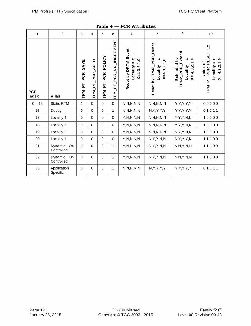
3.7.1 PCR Attributes
PC Client TPM PCRs are defined to enable a PC Client TPM to support DRTM. See Section 4.2.1 DRTM Execution Sequence.
Note that since the hardware that performs the DRTM sequence at locality 4 is not 290
capable of doing TPM2_PCR_Reset(), the TPM_PT_PCR_RESET_L4 attribute is repurposed to indicate the initial state of the PCR (0 or -1) and to indicate which PCR are set to 0 by a successful DRTM Sequence.
1. For a PC Client TPM, a value in the “Reset by TPM2_PCR_Reset for Locality = x” column (column 8) in Table 4 of: 295
a. N (No): a TPM2_PCR_Reset command SHALL NOT reset the indicated PCR.
b. Y (Yes): a TPM2_PCR_Reset command SHALL reset the indicated PCR.
2. For a PC Client TPM, a value in the “Reset by DRTM Event Locality = x” column
(column 7) in Table 4 of:
a. N (No): DRTM Sequence SHALL NOT reset the indicated PCR, 300
b. Y(Yes): DRTM Sequence SHALL reset the indicated PCR.
3. For a PC Client TPM, for each PCR, the value in the “Extended by TPM2_PCR_Extend Locality = x” column (Column 9) in Table 4 of:
a. N (No): a TPM2_PCR_Extend or TPM2_PCR_Event command SHALL NOT extend the indicated PCR. 305
b. Y (Yes): a TPM2_PCR_Extend or TPM2_PCR_Event command SHALL extend the indicated PCR.
4. For a PC Client TPM, the TPM SHALL return the values defined in the “Value of TPM_PT_PCR_RESET_LX” column (Table 4, column 10) in response to a TPM2_GetCapability command. 310
5. The initialization value for each PCR is defined in Section 3.7.2, Table 5.
TPM Profile (PTP) Specification TCG PC Client Platform
Page 12 TCG Published Family “2.0” January 26, 2015 Copyright © TCG 2003 - 2015 Level 00 Revision 00.43
Table 4 — PCR Attributes
1 2 3 4 5 6 7 8 9 10
PCR Index Alias
TP
M_
PT
_P
CR
_S
AV
E
TP
M_
PT
_P
CR
_A
UT
H
TP
M_
PT
_P
CR
_P
OL
ICY
TP
M_
PT
_P
CR
_N
O_
INC
RE
ME
NT
Re
se
t b
y D
RT
M E
ve
nt
Lo
ca
lity
= x
X=
4,3
,2,1
,0
Re
se
t b
y T
PM
2_
PC
R_
Re
se
t
Lo
ca
lity
= x
X=
4,3
,2,1
,0
Ex
ten
de
d b
y
TP
M2
_P
CR
_E
xte
nd
Lo
ca
lity
= x
X=
4,3
,2,1
,0
Va
lue
of
TP
M_
PT
_P
CR
_R
ES
ET
_L
x
Lo
ca
lity
= x
X=
4,3
,2,1
,0
0 – 15 Static RTM 1 0 0 0 N,N,N,N,N N,N,N,N,N Y,Y,Y,Y,Y 0,0,0,0,0
16 Debug 0 0 0 1 N,N,N,N,N N,Y,Y,Y,Y Y,Y,Y,Y,Y 0,1,1,1,1
17 Locality 4 0 0 0 0 Y,N,N,N,N N,N,N,N,N Y,Y,Y,N,N 1,0,0,0,0
18 Locality 3 0 0 0 0 Y,N,N,N,N N,N,N,N,N Y,Y,Y,N,N 1,0,0,0,0
19 Locality 2 0 0 0 0 Y,N,N,N,N N,N,N,N,N N,Y,Y,N,N 1,0,0,0,0
20 Locality 1 0 0 0 0 Y,N,N,N,N N,Y,Y,N,N N,Y,Y,Y,N 1,1,1,0,0
21 Dynamic OS Controlled
0 0 0 1 Y,N,N,N,N N,Y,Y,N,N N,N,Y,N,N 1,1,1,0,0
22 Dynamic OS Controlled
0 0 0 1 Y,N,N,N,N N,Y,Y,N,N N,N,Y,N,N 1,1,1,0,0
23 Application Specific
0 0 0 1 N,N,N,N,N N,Y,Y,Y,Y Y,Y,Y,Y,Y 0,1,1,1,1

TCG PC Client Platform TPM Profile (PTP) Specification
Family “2.0” TCG Published Page 13 Level 00 Revision 00.43 Copyright © TCG 2003 - 2015 January 26, 2015
3.7.2 PCR Initial and Reset Values 315
The contents of the cells in Table 5 are the value that each of the PCRs is initialized to prior to being transformed by the command or sequence called out in the title of each column. The actual transformation is defined in the TPM Library Specification.
Within the scope of specifying the Reset Value for PCRs, the value -1 is defined to be the same size, in bytes, of the digest for the supported Hash Algorithm ID with all bits 320
set to the value of 1.
The column “No H-CRTM Sequence” indicates that no H-CRTM sequence was initiated prior to the TPM receiving the TPM2_Startup (CLEAR) indication. The column “H-CRTM Sequence” indicates that an H-CRTM sequence was initiated prior to the TPM receiving the TPM2_Startup (CLEAR) indication. 325
Table 5 — PCR Initial and Reset Values
PCR Index
TPM2_Startup(CLEAR)
HASH_END (DRTM Sequence)
TPM2_PCR_Reset No H-CRTM Sequence H-CRTM Sequence
0 Locality
Indicator1 Updated per H-CRTM
sequence2 NC
NC
1-15 0 0 NC NC
16 0 0 NC 0
17 -1 -1 Updated per DRTM sequence NC
18-19 -1 -1 0 NC
20-22 -1 -1 0 0
23 0 0 NC 0
Note 1: Locality Indicator is locality at which TPM2_Startup(CLEAR) is received.
Note 2: See Section 4.2.2 H-CRTM Execution Sequence.
NC = No Change

TPM Profile (PTP) Specification TCG PC Client Platform
Page 14 TCG Published Family “2.0” January 26, 2015 Copyright © TCG 2003 - 2015 Level 00 Revision 00.43
3.8 Power Management
While allowed by the LPC specification (if implemented by the TPM), the TPM is designed to be either fully functional (device power management state D0) or not functional (device power management state D3). In practical applications of TPM, 330
power management of the TPM has no real meaning. The TCG specifications define TPM behavior and functions to simplify the TPM’s interactions with the platform’s components including the software. The TPM2_Shutdown (STATE) and TPM2_Startup commands were created as a mechanism for the platform’s software and BIOS to communicate entry into and exit from the D3 Power State. The TPM2_Shutdown 335
(STATE) command allows a Static OS to indicate to the TPM that the platform may enter a low power state where the TPM will be required to enter into the D3 power state. The use of the term “may” is significant in that there is no requirement for the platform to actually enter the low power state after sending the TPM2_Shutdown (STATE) command. The software may, in fact, send subsequent commands after 340
sending the TPM2_Shutdown (STATE) commands. The TPM2_Shutdown (STATE)
command simply tells the TPM to save the required volatile contents because power to the TPM may be removed at any time. The TPM is responsible for tracking its internal state so that, if a command that alters the TPM’s saved state is sent to the TPM after a TPM2_Shutdown (STATE) command, the TPM voids the saved internal state so a 345
subsequent TPM2_Startup(STATE) will fail. In this case, it is the responsibility of platform software to send a subsequent TPM2_Shutdown (STATE) command to preserve the new internal state of the TPM.
It is the responsibility of the S-CRTM to indicate to the TPM using the TPM2_Startup command whether the TPM must reset or restore its saved state (e.g., PCR values, 350
etc.). If the S-CRTM commands the TPM to restore the saved state (i.e., STATE), this restores the transitive trust chain. If the S-CRTM commands the TPM to reset the saved state (i.e., CLEAR), this clears and restarts a new transitive trust state. The rationale here is that the S-CRTM is trusted to establish the initial transitive trust chain, so it should also be trusted to determine whether to restore or clear it. 355
Power management has changed since the original LPC specification and TPM TIS were produced. The LPCPD# pin, as defined in the LPC specification, is a shared pin allowing for a power management protocol for ACPI S3-aware devices on the LPC bus. As TPMs do not know or participate in Suspend to RAM (ACPI S3), this pin has no meaning for a TPM. As such, the implementation of the LPCPD# pin on a TPM is 360
platform and chipset implementation specific. If TPM vendors implement the LPCPD# pin and power management protocol, they should provide documentation indicating the method to disable the function.
In the PC Client TPM Interface Specification 1.3, the concept of a lower power operating mode was introduced which allows a TPM to enter a lower power state under specific 365
considerations. The TPM, if in the idle state, can reduce its power consumption by
shutting down internal functional blocks as long as its SPI or LPC interface and the TPM registers remain active. The intention is to prevent any impact to existing TPM drivers. When the TPM receives a transaction on its interface that would cause it to move from Idle to Ready, the TPM must exit the low power mode within TIMEOUT B. 370
There is no additional signaling or register bits required to transition the TPM into or out of a low power state. Because of the performance limitations of the pre-boot environment, this specification does not allow the TPM to enter a low power state prior to the receipt of a TPM2_Startup command.

TCG PC Client Platform TPM Profile (PTP) Specification
Family “2.0” TCG Published Page 15 Level 00 Revision 00.43 Copyright © TCG 2003 - 2015 January 26, 2015
1. After _TPM_INIT, the TPM SHALL behave as if it is in ACPI Device Power State D0 375
even if it supports ACPI Device Power States D1-D2.
2. The TPM SHALL NOT accept commands unless it is in the ACPI Device Power State D0.
3. The TPM SHALL NOT exit the ACPI Device Power State D3 unless it receives _TPM_INIT. 380
4. The TPM SHALL NOT enter an alternative ACPI Device Power State upon receipt of a TPM2_Shutdown (State) command.
5. If implementing an LPC TPM, the TPM SHALL be implemented to allow for the LPC power management protocol to be disabled by strapping LPCPD# pin HIGH.
6. If implementing an SPI TPM, the TPM MAY support lower power states ONLY if the 385
TPM is in the Idle state.
a. If lower power states are supported, the TPM SHALL respond to requests to
transition to the Ready state within TIMEOUT_B.
b. The TPM SHALL NOT enter any lower power state between receipt of _TPM_INIT and receipt of a TPM2_Startup command. 390
3.9 Self-Test Requirements
The TPM 2.0 Library Specification has three ways for a TPM to test functions and capabilities: TPM2_SelfTest, TPM2_IncrementalTest, and on-demand testing.
The command TPM2_SelfTest provides a flag (FullTest) to allow a caller to control whether the TPM performs a full self-test or a partial self-test. TPM2_IncrementalTest 395
provides a means to specify which capabilities should be tested. On-demand testing allows the TPM to test an untested capability when it is invoked.
To make TPM behavior more deterministic for PC Client platforms, this specification constrains the behavior for TPM2_SelfTest. With the FullTest flag set to yes, the TPM will perform testing so that it mirrors the behavior of the TPM 1.2 SelfTestFull 400
command. With the FullTest flag set to no, the TPM will perform testing so that it mirrors the behavior of the TPM 1.2 ContinueSelfTest command.
This specification does not constrain TPM2_IncrementalTest or on-demand testing.
1. On receipt of TPM2_SelfTest(fullTest == NO), the TPM SHALL return TPM_RC_TESTING and perform background testing of untested functions,. 405
Note: The test status can be retrieved from the TPM using TPM2_GetTestResult.
2. On receipt of TPM2_SelfTest(fullTest == YES), the TPM SHALL perform a full self-test and return the result when all tests are complete.
3.10 Firmware Upgrade
The TPM 2.0 Library Specification provides a standardized mechanism for upgrading a 410
TPM’s firmware. A TPM compliant to this specification must implement a firmware upgrade mechanism but is not required to implement the firmware upgrade specified in the TPM 2.0 Library Specification.
1. A TPM compliant to this specification SHALL implement firmware upgrade.

TPM Profile (PTP) Specification TCG PC Client Platform
Page 16 TCG Published Family “2.0” January 26, 2015 Copyright © TCG 2003 - 2015 Level 00 Revision 00.43
2. A TPM compliant to this specification MAY implement the TPM 2.0 Library 415
Specification defined firmware upgrade.
a. If the TPM implements the Library defined firmware upgrade, the TPM SHALL implement the commands TPM2_FieldUpgrade_Start, TPM2_FieldUpgrade_Data and TPM2_Firmware_Read.

TCG PC Client Platform TPM Profile (PTP) Specification
Family “2.0” TCG Published Page 17 Level 00 Revision 00.43 Copyright © TCG 2003 - 2015 January 26, 2015
4 TPM Capabilities and Commands 420
4.1 Command Table
The TPM 2.0 Library Specification defines the Protected Capabilities (commands) for many types of platforms in a manner that is not platform specific. Not all of the Protected Capabilities in the TPM 2.0 Library Specification are applicable to all platforms, and it is left to the platform specific specifications to enumerate which of 425
the commands are required for TPMs meant to be used in that type of platform.
1. To be compliant with this specification, the TPM SHALL support the commands labeled as mandatory (M) in the column labeled “M / O” in Table 6.
Table 6 — Mandatory/Optional TPM Commands
Commands M / O Comments
Signals / Indications
__TPM_INIT M
_TPM_Hash_Start M
_TPM_Hash_Data M
_TPM_Hash_End M
Startup
TPM2_Startup M
TPM2_Shutdown M
Testing
TPM2_IncrementalSelfTest M
TPM2_SelfTest M
TPM2_GetTestResult M
Session Commands
TPM2_StartAuthSession M
TPM2_PolicyRestart M

TPM Profile (PTP) Specification TCG PC Client Platform
Page 18 TCG Published Family “2.0” January 26, 2015 Copyright © TCG 2003 - 2015 Level 00 Revision 00.43
Commands M / O Comments
Object Commands
TPM2_Create M
TPM2_Load M
TPM2_LoadExternal M
TPM2_ReadPublic M
TPM2_ActivateCredential M
TPM2_MakeCredential M
TPM2_Unseal M
TPM2_ObjectChangeAuth M
Duplicate Commands
TPM2_Duplicate M
TPM2_Rewrap O
TPM2_Import M
Asymmetric Primitives
TPM2_RSA_Encrypt M
TPM2_RSA_Decrypt M
TPM2_ECDH_KeyGen M
TPM2_ECDH_ZGen M
TPM2_ECC_Parameters M
TPM2_ZGen_2Phase O
Symmetric Primitives
TPM2_EncryptDecrypt O
TPM2_Hash M
TPM2_HMAC O
Random Number Generator
TPM2_GetRandom M
TPM2_StirRandom M

TCG PC Client Platform TPM Profile (PTP) Specification
Family “2.0” TCG Published Page 19 Level 00 Revision 00.43 Copyright © TCG 2003 - 2015 January 26, 2015
Commands M / O Comments
Hash/HMAC/Event Sequences
TPM2_HMAC_Start M
TPM2_HashSequenceStart M
TPM2_SequenceUpdate M
TPM2_SequenceComplete M
TPM2_EventSequenceComplete M
Attestation Commands
TPM2_Certify M
TPM2_CertifyCreation M
TPM2_Quote M
TPM2_GetSessionAuditDigest M
TPM2_GetCommandAuditDigest O
TPM2_GetTime O
Anonymous Attestation
TPM2_Commit M
TPM2_ECC_Ephemeral O
Signature Verification
TPM2_VerifySignature M
TPM2_Sign M
Command Audit
TPM2_SetCommandCodeAuditStatus O
Integrity Collection (PCR)
TPM2_PCR_Extend M
TPM2_PCR_Event M
TPM2_PCR_Read M
TPM2_PCR_Allocate M
TPM2_PCR_SetAuthPolicy O
TPM2_PCR_SetAuthValue O
TPM2_PCR_Reset M

TPM Profile (PTP) Specification TCG PC Client Platform
Page 20 TCG Published Family “2.0” January 26, 2015 Copyright © TCG 2003 - 2015 Level 00 Revision 00.43
Commands M / O Comments
Enhanced Authorization (EA)
TPM2_PolicySigned M
TPM2_PolicySecret M
TPM2_PolicyTicket O
TPM2_PolicyOR M
TPM2_PolicyPCR M
TPM2_PolicyLocality M
TPM2_PolicyNV M
TPM2_PolicyCounterTimer M
TPM2_PolicyCommandCode M
TPM2_PolicyPhysicalPresence O Required if a TPM implements Physical Presence
TPM2_PolicyCpHash M
TPM2_PolicyNameHash M
TPM2_PolicyDuplicationSelect M
TPM2_PolicyAuthorize M
TPM2_PolicyAuthValue M
TPM2_PolicyPassword M
TPM2_PolicyGetDigest M
TPM2_PolicyNvWritten M
Hierarchy Commands
TPM2_CreatePrimary M
TPM2_HierarchyControl M
TPM2_SetPrimaryPolicy M
TPM2_ChangePPS O This command may be required for successful completion of a FIPS140-2 evaluation
TPM2_ChangeEPS O This command may be required for successful completion of a FIPS140-2 evaluation
TPM2_Clear M
TPM2_ClearControl M
TPM2_HierarchyChangeAuth M

TCG PC Client Platform TPM Profile (PTP) Specification
Family “2.0” TCG Published Page 21 Level 00 Revision 00.43 Copyright © TCG 2003 - 2015 January 26, 2015
Commands M / O Comments
Dictionary Attack Functions
TPM2_DictionaryAttackLockReset M
TPM2_DictionaryAttackParameters M
Miscellaneous Management Functions
TPM2_PP_Commands O
TPM2_SetAlgorithmSet O
Field Upgrade
TPM2_FieldUpgradeStart
O All of these commands are required if any is implemented
TPM2_FieldUpgradeData
TPM2_FirmwareRead
Context Management
TPM2_ContextSave M
TPM2_ContextLoad M
TPM2_FlushContext M
TPM2_EvictControl M
Clocks and Timers
TPM2_ReadClock M
TPM2_ClockSet M
TPM2_ClockRateAdjust M
Capability Commands
TPM2_GetCapability M
TPM2_TestParms M

TPM Profile (PTP) Specification TCG PC Client Platform
Page 22 TCG Published Family “2.0” January 26, 2015 Copyright © TCG 2003 - 2015 Level 00 Revision 00.43
Commands M / O Comments
Non-volatile Storage
TPM2_NV_DefineSpace M
TPM2_NV_UndefineSpace M
TPM2_NV_UndefineSpaceSpecial M
TPM2_NV_ReadPublic M
TPM2_NV_Write M
TPM2_NV_Increment M
TPM2_NV_Extend M
TPM2_NV_SetBits M
TPM2_NV_WriteLock M
TPM2_NV_GlobalWriteLock O
TPM2_NV_Read M
TPM2_NV_ReadLock M
TPM2_NV_ChangeAuth M
TPM2_NV_Certify O
4.2 Locality-Controlled Functions 430
4.2.1 DRTM Execution Sequence
The Dynamic RTM is started while the platform may be in an untrusted state. Special and trusted mechanisms must be established to communicate the source of the corresponding commands to the TPM. These commands are indicated and controlled by the appropriate locality. 435
Locality 4 has the unique ability to reset the Locality 4 PCR. It can also use HASH_DATA to send data to the TPM to be hashed and extended to the Locality 4 PCR. There is no header or other information that accompanies the data, for the FIFO interface. For the CRB interface, the first two bytes of the data contain the size of the data to be hashed. Upon receipt of HASH_END, the TPM will initialize the PCR, 440
complete the hash, and extend the resultant value into the Locality 4 PCR, as defined in the TPM 2.0 Library Specification.
The Locality 4 PCR (PCR[17]) contains the first measurement of the Dynamic RTM for the Dynamic OS. Because the security of the Dynamic Launch is dependent solely on the reset and initial measurement in the Locality 4 PCR, access to Locality 4’s extend 445
operations should not have security implications.
It is expected that any PC Client platform is designed such that the platform protects Locality 4 access to the TPM, ensuring access only from platform components operating at Locality 4.

TCG PC Client Platform TPM Profile (PTP) Specification
Family “2.0” TCG Published Page 23 Level 00 Revision 00.43 Copyright © TCG 2003 - 2015 January 26, 2015
Note: For a DRTM sequence (HASH_START/_DATA/_END) to occur, the TPM must 450
have received a TPM2_Startup command prior to the HASH_START. If the TPM receives HASH_START after a __TPM_INIT but before a startup command, the TPM treats this as H-CRTM sequence,
The data written to the TPM_HASH_START and TPM_HASH_DATA interface registers of the FIFO interface has no significance and may be any value. 455
Note: For the CRB interface, an optimization allows both the TPM_HASH_DATA and TPM_HASH_END fields of the TPM_LOC_CTRL_4 register to be SET in the same write cycle.

TPM Profile (PTP) Specification TCG PC Client Platform
Page 24 TCG Published Family “2.0” January 26, 2015 Copyright © TCG 2003 - 2015 Level 00 Revision 00.43
Some arbitrary time later
TimePlatform Components /
Driver
Command
TPM Action
If Locality == 3 or 4;
then TpmEstablished bit := 1
Write of 1 to interface
specific mechanism to
reset TpmEstablishment
bit.
Perform an extend operation on tempLocal
into PCR[17]
Release Locality
Ignore any data sentHASH_END
No response returned
Transform data received in FIFO into
tempLocal per Hash AlgIDNote: Writes to TPM_HASH_DATA/FIFO are
interpreted only as data, not a command.
HASH_DATA
No response returned
Ignore any data sent
tpmEstablished bit := 0
Set PCRs per section covering PCR reset
(e.g., PCR[17-22] := 0)
Allocate and initialize tempLocal per Hash
AlgID
If Locality is set then
if Locality is 4 then continue
else abort
else
set TPM to Locality 4
HASH_START
No response returned
Figure 1 — Overview of D-CRTM Measurement Sequence
1. A DRTM sequence is started by a HASH_START which occurs following a 460
TPM2_Startup command.

TCG PC Client Platform TPM Profile (PTP) Specification
Family “2.0” TCG Published Page 25 Level 00 Revision 00.43 Copyright © TCG 2003 - 2015 January 26, 2015
a. A HASH_START is either:
i. In the FIFO interface, a successful write to the TPM_HASH_START interface register, or
ii. In the CRB interface, a successful write to the TPM_LOC_CTRL_4 interface 465
register with the TPM_HASH_START field SET.
2. DRTM data is provided by a HASH_DATA which occurs following a HASH_START
a. A HASH_DATA is either:
i. In the FIFO interface, a successful write to the TPM_HASH_DATA interface register, or 470
ii. In the CRB interface, a successful write of two or more bytes to the command buffer followed by a write to the TPM_LOC_CTRL_4 interface register with the TPM_HASH_DATA field SET.
Note: The first two bytes in the command buffer, in big endian notation, indicate the number of bytes to be hashed when HASH_DATA is received. 475
3. A DRTM sequence is completed by a HASH_END that follows a HASH_START
a. A HASH_END is either:
i. In the FIFO interface, a successful write to the TPM_HASH_END interface register, or
ii. In the CRB interface, a successful write to the TPM_LOCK_CTRL_4 interface 480
register with the TPM_HASH_END field SET.
4. Upon receipt of HASH_START, the TPM SHALL follow the protocol below and perform the operations in the following pseudo-code to affect the resettable PCRs:
Note: While the resulting functionality presented by the steps below is normative, the actual operations and their sequence as presented here are informative. There 485
is no requirement to perform the following operations exactly as shown. However implemented, the results are required to be the same as if the TPM were implemented as described below.
a. HASH_START: Upon receipt of this interface command, the TPM SHALL:
i. If no Locality field is set, SET the active Locality field to indicate Locality 4. 490
ii. If a locality is active, and if the active Locality field is not 4, ignore this command.
iii. Clear the write buffer (FIFO only).
Note: If the FIFO is cleared as a result of relinquishing locality, this step may be omitted. 495
iv. If there is an exclusive session, the TPM SHALL have no exclusive session following the HASH_START.
v. Ignore any data component of this interface command.
vi. Perform operations per TPM 2.0 Library Specification for the _TPM_Hash_Start indication. 500
TPM Profile (PTP) Specification TCG PC Client Platform
Page 26 TCG Published Family “2.0” January 26, 2015 Copyright © TCG 2003 - 2015 Level 00 Revision 00.43
b. HASH_DATA: Upon receipt of this interface command, the TPM SHALL perform operations as defined in TPM 2.0 Library Specification for the _TPM_Hash_Data indication.
c. HASH_END: Upon receipt of this interface command, the TPM SHALL:
i. CLEAR the Establishment bit. 505
Note: See description of Bit Field: Establishment bit in Section 5.5.2.4 Access Register and Section 5.5.3.2.1 Locality State Register.
ii. Set to 0 all PCR which are reset by a DRTM event as indicated by Table 4.
iii. Perform the hash functions as if TPM2_PCR_Event command was being used. 510
Note: This is consistent with the Hash Interface Command in TPM 1.2.
iv. Perform operations as defined in TPM 2.0 Library Specification for the _TPM_Hash_End indication
v. Clear active Locality.
Note: The write buffer is cleared as a result of relinquishing locality for both 515
the FIFO and CRB interfaces.
d. After successful completion of HASH_START and before HASH_END:
i. For the FIFO interface, all cycles and commands other than writes to the TPM_HASH_DATA and TPM_HASH_END interface registers SHALL be ignored until HASH_END 520
ii. For the CRB interface, all cycles and commands other than writes to the Command Buffer and TPM_LOC_CTRL_4 registers SHALL be ignored until HASH_END.
e. Upon any error in the above steps the TPM SHALL release locality and enter Failure Mode. 525
Note: No response packet is returned for HASH_START, HASH_DATA, or HASH_END.
4.2.2 H-CRTM Sequence Before TPM2_Startup() and TPM2_Startup() without H-CRTM
The Hardware CRTM is started in the earliest stage of platform boot and is initiated by 530
a CPU. The H-CRTM sequence only applies to PCR 0 if the sequence is initiated prior to a TPM2_Startup command. The actions of the sequence are identical to that of a DRTM sequence with the exception of the value to which the PCR is initialized and when the PCR is initialized and extended.
1. A TPM_Startup command SHALL come from Locality 0 or 3, else the TPM SHALL 535
return TPM_RC_Locality.
2. Upon receipt of a HASH_START, the TPM follows the protocol below and performs the operations in the following pseudo-code to affect PCR 0:
Note: While the resulting functionality presented by the steps below is normative, the actual operations and their sequence as presented here are informative. There 540
is no requirement to perform the following operations exactly as shown. However

TCG PC Client Platform TPM Profile (PTP) Specification
Family “2.0” TCG Published Page 27 Level 00 Revision 00.43 Copyright © TCG 2003 - 2015 January 26, 2015
implemented, the results SHALL be the same as if the TPM were implemented as described below.
a. HASH_START: Upon receipt of this interface command, the TPM SHALL:
i. If no Locality field is set, set the active Locality field to indicate Locality 4. 545
ii. If a locality is active, and if the active Locality field is not 4, ignore this command.
iii. Perform operations as defined in TPM 2.0 Library Specification _TPM_Hash_Start indication.
b. HASH_DATA: Upon receipt of this interface command, the TPM SHALL perform 550
operations as defined in TPM 2.0 Library Specification _TPM_Hash_Data indication.
Note: For the CRB interface, bytes 0 and 1 of the data written to the command buffer contain the length of the subsequent data to be extended.
c. HASH_END: Upon receipt of this interface command, the TPM SHALL: 555
i. Perform operations as defined in TPM 2.0 Library Specification _TPM_Hash_End
ii. Clear activeLocality.
4.2.3 Timing and Protocol
The DRTM and H-CRTM sequences execute within a resource-restricted environment 560
which is among the reasons the HASH_START/_DATA/_END protocol is used rather than the more obvious TPM command ordinals (e.g., TPM2_PCR_Extend). It is also difficult and unnecessary for this environment to use the register-based protocols. Therefore, during the Locality 4 HASH_START/_DATA/_END sequence, the only method to throttle commands to the TPM uses the bus wait mechanism. (There is no 565
data returning from TPM within this environment.) Specifically, the TPM uses the LPC bus “long wait” sync (using LPC terms) or SPI wait cycles as defined in Section 6.4.5 Flow Control to indicate to the “host” that it is not able to accept more data.
This environment also may not be conducive to “timeouts” and may be very susceptible to delays or hangs. It is important that the TPM be designed to avoid 570
excessive delays and should not cause the bus to hang during this time.
1. During the HASH_START/_DATA/_END sequence, the TPM SHALL use the appropriate bus wait mechanism (LPC bus “long wait sync” or SPI “wait cycle”) to indicate its inability to accept more commands or data. While the TPM MAY set the TPM_STS_x or TPM_CRB_CTRL_REQ_x fields they are “undefined” during these 575
commands (i.e. will likely not be read and will not be honored).
2. The TPM SHALL respond to HASH_START within TIMEOUT_B.
3. The TPM SHOULD respond to each HASH_DATA and HASH_END within 250 microseconds and SHALL respond within TIMEOUT_B.
TPM Profile (PTP) Specification TCG PC Client Platform
Page 28 TCG Published Family “2.0” January 26, 2015 Copyright © TCG 2003 - 2015 Level 00 Revision 00.43
5 TPM Software Interface 580
5.1 Interface Type
This specification defines a new software interface to the TPM for TPM 2.0, in addition to the FIFO interface. This interface, the Command Response Buffer Interface, has been defined so that it may be implemented in a TPM which also contains a FIFO interface. The CRB Interface is intended to be physical-bus agnostic, so that it could 585
be implemented on an LPC or SPI interface, as specified in this specification or on another physical interface not specified. In order for a TPM to be compliant with this specification, however, it is required to implement at least one of the interfaces defined by this specification.
The physical register spaces for both FIFO and CRB are specified in Section 5.3 TPM 590
Register Space. Register space with functions common to both interfaces is specified in Section 5.5.1 Interface Agnostic Functions. The behavior of the CRB Interface is specified in Section 5.5.3 CRB Interface Requirements. In the subsequent sections, functionality which is interface-independent precedes the interface-specific functionality. Where a function is common to both interfaces, but there are interface-595
specific requirements, the requirements are documented in the interface-specific section. For example, the concepts of Locality are common to both interfaces, but the mechanisms to invoke locality are interface specific.
1. A TPM compliant with this specification SHALL implement at least one of the following interfaces: 600
a. Command Response Buffer (CRB) Interface, or
b. FIFO Interface
2. The TPM SHALL implement the InterfaceType field in the interface specific Interface Identifier register, TPM_INTERFACE_ID_x for FIFO and TPM_CRB_INTF_ID_x for CRB. 605
3. A TPM which supports both interface types SHALL expose only one Interface at a time.
4. The mechanism for switching between interfaces SHALL be implemented as defined in Section 5.4.2 Interface Identifier Register.
5.2 Locality 610
Locality Priority is described in Section 2.2 Locality.
5.2.1 TPM Locality Levels
TPM 2.0 supports five levels of locality: Locality None and Locality 0-4. PC Client platform usage of locality levels is defined in the PC Client Implementation Specification. 615
The usage of PCRs with respect to locality is defined in Section 3.7.1 PCR Attributes.

TCG PC Client Platform TPM Profile (PTP) Specification
Family “2.0” TCG Published Page 29 Level 00 Revision 00.43 Copyright © TCG 2003 - 2015 January 26, 2015
For the platform, the locality level is indicated by the address used along with the TPM bus Start cycle. For system software, the TPM has a 64 bit address of 0x0000_0000_FED4_xxxx. On LPC, the chipset passes the least significant 16 bits to the TPM. On SPI, the chipset passes the least significant 24 bits to the TPM. The 620
upper bytes will be used by the chipset to select the TPM’s SPI CS# signal. Table 7 shows the locality based on the 16 least significant address bits and assume that either the LPC TPM sync or SPI TPM CS# is used. Note that previous versions of this specification defined an LPC bus cycle to communicate with the TPM. This was done to prevent simple hardware attacks using a device on the LPC bus that decoded I/O or 625
memory cycles using the previously defined START field. Cycles using the normal memory read/write or I/O read/write START field to the following ranges are not decoded by the TPM.
TPM commands, e.g. TPM2_PCR_Reset, may also require locality. The TPM, upon receipt of each command, sets (based on the TPM register Address) the locality for the 630
command. Locality, as presently defined, may be Locality 0 through 4.
Table 7 — Locality Address Definitions
System/Software Address
TPM Address on LPC (Using TPM START Cycle)
TPM Address on SPI Locality
FED4_0xxxh 0xxxh D4_0xxxh 0
FED4_1xxxh 1xxxh D4_1xxxh 1
FED4_2xxxh 2xxxh D4_2xxxh 2
FED4_3xxxh 3xxxh D4_3xxxh 3
FED4_4xxxh 4xxxh D4_4xxxh 4
When the TPM is in a “free” state, it must be prepared to accept HASH_START (See 4.2 Locality-Controlled Functions).
Note on locality priority: 635
The statements in 2.2 Locality regarding locality hierarchy notwithstanding, the selection of localities has a priority. If two localities have requested use of the TPM when the current locality relinquishes it, the locality with the highest priority gets access to the TPM. The locality’s priority increases as its locality number increases. i.e., Locality 0 has the lowest priority while Locality 4 has the highest. 640
Note on Locality 4 management:
Locality 4 accesses are controlled by trusted hardware responsible for maintaining the DRTM, and software should not use Locality 4 commands. Trusted hardware should be implemented so that Locality 4 operations are not accessible to software.
If the active Locality is a locality other than 4, HASH_START is ignored. If there is no 645
locality set, HASH_START makes Locality 4 the active locality. Once the HASH_DATA sequence is completed at Locality 4, HASH_END releases locality 4 and returns the TPM to a “free” state.
1. The TPM SHALL maintain the relationship between Locality and the locality attribute as defined in Table 8. 650
2. For the purpose of assigning locality, when the host software has requested use of the TPM using either the Locality request method or Seize method, the locality with

TPM Profile (PTP) Specification TCG PC Client Platform
Page 30 TCG Published Family “2.0” January 26, 2015 Copyright © TCG 2003 - 2015 Level 00 Revision 00.43
the highest numeric value has the highest priority. i.e., Locality 1 has a higher priority than Locality 0.
3. When the TPM is at the “free” state, it SHALL accept a write to any of the 655
TPM_HASH_x registers (FIFO interface) or the TPM_LOC_CTRL_4 register (CRB interface).
Table 8 — Relationship between Locality and Locality Attribute
Locality Value of LocalityIndicator
Locality 0 01h
Locality 1 02h
Locality 2 04h
Locality 3 08h
Locality 4 10h
5.2.2 Locality Uses
Usage of Locality 0 PCRs is determined by the TCG PC Client Specific Implementation 660
Specification. Usage of Locality 1-3 PCRs is reserved for uses which are outside the purview of this specification.
The idea behind locality is that certain combinations of software and hardware are allowed more privileges than other combinations. For instance, the highest level of locality might be cycles that only hardware could create. 665
While higher localities may exist, Locality 4 is the highest locality level defined. These cycles are generated by hardware in support of the DRTM. Cycles which require Locality 4 would include things such as the HASH_START/_DATA/_END interface commands.
As an example, assume a platform, including software, has an operating system based 670
on the Static RTM or Static OS, based on either using no PCRs or the set of non-resettable PCRs(0-15), and trusted software, the dynamically launched operating system, or Dynamic OS, which uses the resettable PCRs (17-22). In this case, there is a need to differentiate cycles originating from the two operating systems. Localities 1-3 are used by the Dynamic OS for its transactions. The Dynamic OS has created certain 675
values in the resettable PCRs. Only the Dynamic OS should be able to issue commands based on those PCRs. The Static OS uses Locality 0.
The non-resettable PCRs (i.e., PCR[0-15]) are not part of the Dynamic OS’s domain, so Locality 0 transactions can freely use those PCRs, but must be prevented from resetting or extending PCRs used by the Dynamic OS (see Section 3.7.1 PCR 680
Attributes for the PCR’s which are resettable by the Dynamic OS).
Note to Platform and OS Implementers:
Each RTM (e.g., the DRTM) has a root PCR associated with it. The fundamental trusted boot requirement is that when the RTM is initiated/reset its associated root PCR must also be reset. Conversely, the root PCR must never be reset unless its 685
associated RTM is also initialized/reset. When launching the Dynamic OS, the root dynamic PCR must only be reset when the DRTM is initiated/reset.

TCG PC Client Platform TPM Profile (PTP) Specification
Family “2.0” TCG Published Page 31 Level 00 Revision 00.43 Copyright © TCG 2003 - 2015 January 26, 2015
The TPM architecture doesn’t provide the TPM with a method for controlling access to any of its localities, therefore, controlling access to the various localities is up to either the platform components or the OS. However, even the Dynamic OS must not be 690
allowed to reset the root Dynamic PCR because the Dynamic OS is what is measured into this PCR. Therefore, the platform components must restrict access to Locality 4 to only the D-CRTM components. This is to protect the resetting of the root Dynamic PCR (i.e., PCR[17]). (Note that because some TPMs have implemented the command FIFO for Locality 4, the platform must protect the entire Locality 4 address range to prevent 695
unauthorized software from executing the TPM2_PCR_Reset command on PCR[17] at Locality 4.)
While the Dynamic OS is executing, the platform components may provide software access to localities other than 4. In this case, if the Dynamic OS requires protection for these localities it must protect them using methods such as virtual memory 700
management (i.e., paging).
1. The TPM SHALL enforce locality access to each TPM resource that requires locality (such as PCRs) or uses TPM2_PolicyLocality() in its authorization policy.
5.3 TPM Register Space
5.3.1 TPM Register Space Decode 705
Many of the registers in the TPM Register Space are defined using a contiguous address range within a given locality. There are common requirements for decoding the address space between the FIFO register space and the CRB register space. These common requirements are documented in this section. The actual address space for FIFO and CRB is different and there are some unique restrictions. The interface 710
specific information is documented in the subsequent sections for each interface.
FIFO Register Space Decode
Most of the FIFO registers are accessed with the TPM decoding all addresses within the specified address ranges. For registers with the same function for different localities, the address range for one locality is not contiguous with the address range 715
for a different locality. Some of these registers which are defined separately with separate address ranges, e.g. the TPM_STS_x register, may be mirrored such that each separate address range (for example 0x001A to 0x0018 for TPM_STS_0 and 0x101A_0x1018 for TPM_STS_1) points to the same physical register.
Another one of the registers which is defined as having five addresses is the TPM data 720
register (TPM_DATA_FIFO_x). For this register, the addresses within this range may be aliased to one internal register.
Note that the addresses allocated for the Locality 4 HASH* commands do not exist in Localities 0-3.
CRB Register Space Decode 725
The CRB address space is a contiguous space that may be instantiated in hardware or in ACPI AddressRangeReserved memory. When a TPM implements a CRB in hardware, the register space is defined in the Section 5.5.3 CRB Interface Requirements.

TPM Profile (PTP) Specification TCG PC Client Platform
Page 32 TCG Published Family “2.0” January 26, 2015 Copyright © TCG 2003 - 2015 Level 00 Revision 00.43
General Address Space Decode Considerations 730
The LPC bus transfers a single byte per transaction to any of the registers. The chipset may, for performance reasons, send a DW (4 bytes) for each transaction. This will appear as four distinct LPC bus transactions, with each incrementing the address by 1 byte with each set of transactions starting with the least significant byte – thus being little-endian. Because the TPM can accept only 1 byte per transaction, the TPM must 735
ignore the 2 least significant bits of the address for the data registers thus receiving the data serially. However, it should not require or expect that each address is incremented modulo-4.
The SPI bus does not limit transfers to a single byte. The extended size data register (TPM_XDATA_FIFO_x) and CRB data buffer allow a single write to offset 0x0080h up to 740
64B, without requiring software to increment the address. It is technically possible to send a single transaction on SPI that spans more than one register in the TPM’s address space. Software should never attempt to access multiple registers in a single transaction. Software should access each register in unique, individual transactions and not attempt to cross register boundaries. Software may access only part of a 745
register, e.g. read or write one byte of a 4 byte register. Software should not initiate a transaction that is either larger than the register size (2 byte access to a 1 byte register), or that extends beyond the defined register boundary (2 byte transaction to offset 0x3 of a register defined as existing within the address range of 0x0 to 0x3). This is simply good software behavior and these guidelines are not specific to TPM 750
transactions, but apply to all hardware and software.
Because the TPM must be designed to handle cases where software behaves badly, this specification defines behavior for the TPM in the event that a transaction crosses multiple registers. TPM vendors should design their hardware so that bad software does not impact the state or security of the TPM. Specific error behavior is specified in 755
Section 5.5.1.8 Errors.
1. A TPM compliant with this specification SHALL implement an Interface Identifier register:
a. A TPM which only supports the FIFO interface SHALL support the TPM_INTERFACE_ID_x register. 760
b. A TPM which supports a CRB interface SHALL support the TPM_CRB_INTF_ID_x register.
2. For SPI, if a TPM receives an access request with a length that exceeds the size of the register specified in the transaction address:
a. Reads: 765
i. The TPM SHALL return the data for the register designated by the start address.
ii. The TPM MAY return the data for additional, adjacent registers within the targeted address range, or the TPM MAY return dummy data for additional, adjacent registers within the targeted address range. 770
b. Writes:
i. The TPM SHALL update the register designated by the start address.
ii. The TPM MAY update additional, adjacent registers within the targeted address range.

TCG PC Client Platform TPM Profile (PTP) Specification
Family “2.0” TCG Published Page 33 Level 00 Revision 00.43 Copyright © TCG 2003 - 2015 January 26, 2015
iii. The TPM SHALL NOT change the state of adjacent registers if the writes to 775
that register are dropped.
c. The TPM SHOULD NOT abort (as defined in Section 5.5.1.1 Bus Aborts) an entire transaction that crosses a register boundary.
d. When a transaction crosses a register boundary, the TPM SHALL NOT allow data from that transaction to corrupt future SPI transactions. 780
3. For the FIFO data buffers:
a. TPM_DATA_FIFO_x The TPM SHALL ignore the 2 least significant bits of the address for these registers and accept each byte received to any of the addresses within this register as a single transfer to the base address. 785
b. TPM_XDATA_FIFO_x
The TPM SHALL accept transactions to offset 0x0080h which are of any length
from 1 byte to the maximum supported length (as reported in the Interface Capability register, Section 5.5.2.7 Interface Capability).
4. The TPM MAY accept transactions to offset 0x0081h-0x0083h which are of lengths 790
between 3 bytes-1 byte.
Note: This behavior mirrors the behavior of the TPM_DATA_FIFO_x.
5. The TPM MAY accept transactions to offset 0x0080h which are of lengths larger than the maximum supported length (as reported in the Interface Capability register, see Section 5.5.2.7 Interface Capability), based on the existing interface 795
protocol using TPM_STS_x.burstCount and TPM_STS_x.Expect as defined in Section 5.5.2.4 Access Register.
a. All other registers:
i. The TPM SHALL fully decode the address down to the byte level (unless otherwise specified). 800
ii. The TPM SHALL interpret registers that have multiple addresses as follows:
(a) The lowest address within the set of addresses contains the least significant byte with the bits incrementing to each successive address up to the highest address which contains the most significant byte.
Note: Addresses are implemented as in Table 9. 805
6. For the CRB Interface, as all registers are aligned on either 32-bit or 64-bit address boundaries, the following restrictions apply:
a. For an access with a start address for an address aligned on a 32-bit boundary with a length larger than 32 bits:
i. For write transactions, 810
ii. The TPM MAY update the register with the start address equal to the transaction start address and wholly contained within the transaction address.
(1) The TPM MAY ABORT (as defined in Section 5.5.1.1 Bus Aborts) the transaction. 815

TPM Profile (PTP) Specification TCG PC Client Platform
Page 34 TCG Published Family “2.0” January 26, 2015 Copyright © TCG 2003 - 2015 Level 00 Revision 00.43
(2) The TPM SHALL not update any register whose start address is not equal to the start address of the transaction.
iii. For read transactions,
(1) The TPM MAY return the response data for the register with the start address equal to the transaction start address and wholly contained 820
within the transaction address.
(2) The TPM MAY ABORT (as defined in Section 5.5.1.1 Bus Aborts) the transaction.
Table 9 — Example Bit-to-Address Mapping
Address Data Bit Position Example
0x00000008 7:0 0000 0000 0000 0000 0000 0000 0000 1000
0x00000900 15:8 0000 0000 0000 0000 0000 1001 0000 0000
0x000A0000 23:16 0000 0000 0000 1010 0000 0000 0000 0000
0x0B000000 31:24 0000 1011 0000 0000 0000 0000 0000 0000

TCG PC Client Platform TPM Profile (PTP) Specification
Family “2.0” TCG Published Page 35 Level 00 Revision 00.43 Copyright © TCG 2003 - 2015 January 26, 2015
5.3.2 Register Space Addresses 825
Table 10 lists a comparison of the addresses decoded by the TPM when FIFO or CRB (in hardware) is implemented.
Table 10 — Allocation of Register Space for FIFO and CRB Access
Offset FIFO Register Name CRB Register Name
Locality 0
0000h TPM_ACCESS_0
TPM_LOC_STATE_0 0001h
Reserved 0002h
0003h
0007h-0004h Reserved
000Bh-0008h TPM_INT_ENABLE_0 TPM_LOC_CTRL_0
000Ch TPM_INT_VECTOR_0 TPM_LOC_STS_0
000Fh-000Dh Reserved
0013h-0010h TPM_INT_STATUS_0
Reserved
0017h-0014h TPM_INTF_CAPABILITY_0
001Bh-0018h TPM_STS_0
0023h-001Ch Reserved
0027h_0024h TPM_DATA_FIFO_0
002Fh-0028h Reserved
0033h-0030h TPM_INTERFACE_ID_0 TPM_CRB_INTF_ID_0
0037h-0034h
Reserved
003Fh-0038h TPM_CRB_CTRL_EXT
0043h-0040h TPM_CRB_CTRL_REQ_0
0047h-0044h TPM_CRB_CTRL_STS_0
004Bh-0048h TPM_CRB_CTRL_CANCEL_0
004Fh-004Ch TPM_CRB_CTRL_START_0
0053h-0050h TPM_CRB_ INT_ENABLE_0
0057h-0054h TPM_CRB_INT_STS_0
005Bh-0058h TPM_CRB_CTRL_CMD_SIZE_0
005Fh-005Ch TPM_CRB_CTRL_CMD_LADDR_0
0063h-0060h TPM_CRB_CTRL_CMD_HADDR_0
0067h-0064h TPM_CRB_CTRL_RSP_SIZE_0
006Fh-0068h TPM_CRB_CTRL_RSP_ADDR_0
007Fh-0070h Reserved
0083h-0080h TPM_XDATA_FIFO_0 TPM_CRB_DATA_BUFFER_0
0880h-0084h Reserved
0EFFh-0881h
Reserved 0F03h-0F00h TPM_DID_VID_0
0F04h TPM_RID_0
0FFFh-0F90h Reserved

TPM Profile (PTP) Specification TCG PC Client Platform
Page 36 TCG Published Family “2.0” January 26, 2015 Copyright © TCG 2003 - 2015 Level 00 Revision 00.43
Offset FIFO Register Name CRB Register Name
Locality 1
1000h TPM_ACCESS_1
TPM_LOC_STATE_1 1001h
Reserved 1002h
1003h
1007h-1004h Reserved
100Bh-1008h TPM_INT_ENABLE_1 TPM_LOC_CTRL_1
100Ch TPM_INT_VECTOR_1 TPM_LOC_STS_1
100Fh-100Dh Reserved
1013h-1010h TPM_INT_STATUS_1
Reserved
1017h-1014h TPM_INTF_CAPABILITY_1
101Bh-1018h TPM_STS_1
1023h-101Ch Reserved
1027h-1024h TPM_DATA_FIFO_1
102Fh-1028h Reserved
1033h-1030h TPM_INTERFACE_ID_1 TPM_CRB_INTF_ID_1
1037h-1032h
Reserved
103Fh-1038h Reserved
1043h-1040h TPM_CRB_CTRL_REQ_1
1047h-1044h TPM_CRB_CTRL_STS_1
104Bh-1048h TPM_CRB_CTRL_CANCEL_1
104Fh-104Ch TPM_CRB_CTRL_START_1
1053h-1050h TPM_CRB _INT_ENABLE_1
1057h-1054h TPM_CRB_INT_STS_1
105Bh-1058h TPM_CRB_CTRL_CMD_SIZE_1
105Fh-105Ch TPM_CRB_CTRL_CMD_LADDR_1
1063h-1060h TPM_CRB_CTRL_CMD_HADDR_1
1067h-1064h TPM_CRB_CTRL_RSP_SIZE_1
106Fh-1068h TPM_CRB_CTRL_RSP_ADDR_1
107Fh-1070h Reserved
1083h-1080h TPM_XDATA_FIFO_1 TPM_CRB_DATA_BUFFER_1
1880h-1084h Reserved
1EFFh-1881h
Reserved 1F03h-1F00h TPM_DID_VID_1
1F04h TPM_RID_1
1FFFh-1F05h Reserved

TCG PC Client Platform TPM Profile (PTP) Specification
Family “2.0” TCG Published Page 37 Level 00 Revision 00.43 Copyright © TCG 2003 - 2015 January 26, 2015
Offset FIFO Register Name CRB Register Name
Locality 2
2000h TPM_ACCESS_2
TPM_LOC_STATE_2 2001h
Reserved
2002h
2003h
2007h-2004h Reserved
200Bh-2008h TPM_INT_ENABLE_2 TPM_LOC_CTRL_2
200Ch TPM_INT_VECTOR_2 TPM_LOC_STS_2
200Fh-200Dh Reserved
2013h-2010h TPM_INT_STATUS_2
Reserved
2017h-2014h TPM_INTF_CAPABILITY_2
201Bh-2018h TPM_STS_2
2023h-201Ch Reserved
2027h-2024h TPM_DATA_FIFO_2
202Fh-2028h Reserved
2033h-2030h TPM_INTERFACE_ID_2 TPM_CRB_INTF_ID_2
2037h-2032h
Reserved
203Fh-2038h Reserved
2043h-2040h TPM_CRB_CTRL_REQ_2
2047h-2044h TPM_CRB_CTRL_STS_2
204Bh-2048h TPM_CRB_CTRL_CANCEL_2
204Fh-204Ch TPM_CRB_CTRL_START_2
2053h-2050h TPM_CRB_ INT_ENABLE_2
2057h-2054h TPM_CRB_INT_STS_2
205Bh-2058h TPM_CRB_CTRL_CMD_SIZE_2
205Fh-205Ch TPM_CRB_CTRL_CMD_LADDR_2
2063h-2060h TPM_CRB_CTRL_CMD_HADDR_2
2067h-2064h TPM_CRB_CTRL_RSP_SIZE_2
206Fh-2068h TPM_CRB_CTRL_RSP_ADDR_2
207Fh-2070h Reserved
2083h-2080h TPM_XDATA_FIFO_2 TPM_CRB_DATA_BUFFER_2
2880h-2084h Reserved
2EFFh-2881h
Reserved 2F03h-2F00h TPM_DID_VID_2
2F04h TPM_RID_2
2FFFh-2F05h Reserved

TPM Profile (PTP) Specification TCG PC Client Platform
Page 38 TCG Published Family “2.0” January 26, 2015 Copyright © TCG 2003 - 2015 Level 00 Revision 00.43
Offset FIFO Register Name CRB Register Name
Locality 3
3000h TPM_ACCESS_3
TPM_LOC_STATE_3 3001h
Reserved
3002h
3003h
3007h-3004h Reserved
300Bh-3008h TPM_INT_ENABLE_3 TPM_LOC_CTRL_3
300Ch TPM_INT_VECTOR_3 TPM_LOC_STS_3
300Fh-300Dh Reserved
3013h-3010h TPM_INT_STATUS_3
Reserved
3017h-3014h TPM_INTF_CAPABILITY_3
301Bh-3018h TPM_STS_3
3023h-301Ch Reserved
3027h-3024h TPM_DATA_FIFO_3
302Fh-3028h Reserved
3033h-3030h TPM_INTERFACE_ID_3 TPM_CRB_INTF_ID_3
3037h-3032h
Reserved
303Fh-3038h Reserved
3043h-3040h TPM_CRB_CTRL_REQ_3
3047h-3044h TPM_CRB_CTRL_STS_3
304Bh-3048h TPM_CRB_CTRL_CANCEL_3
304Fh-304Ch TPM_CRB_CTRL_START_3
3053h-3050h TPM_CRB _INT_ENABLE_3
3057h-3054h TPM_CRB_INT_STS_3
305Bh-3058h TPM_CRB_CTRL_CMD_SIZE_3
305Fh-305Ch TPM_CRB_CTRL_CMD_LADDR_3
3063h-3060h TPM_CRB_CTRL_CMD_HADDR_3
3067h-3064h TPM_CRB_CTRL_RSP_SIZE_3
306Fh-3068h TPM_CRB_CTRL_RSP_ADDR_3
307Fh-3070h Reserved
3083h-3080h TPM_XDATA_FIFO_3 TPM_CRB_DATA_BUFFER_3
3880h-3084h Reserved
3EFFh-3881h
Reserved 3F03h-3F00h TPM_DID_VID_3
3F04h TPM_RID_3
3FFFh-3F05h Reserved
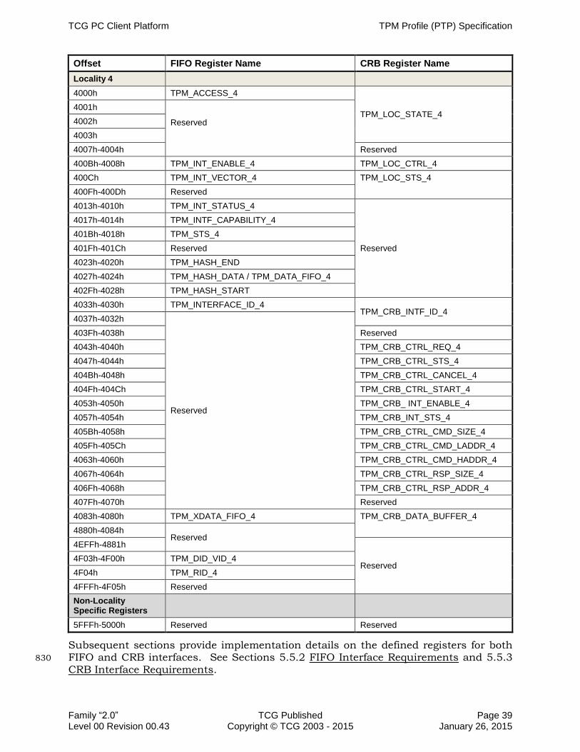
TCG PC Client Platform TPM Profile (PTP) Specification
Family “2.0” TCG Published Page 39 Level 00 Revision 00.43 Copyright © TCG 2003 - 2015 January 26, 2015
Offset FIFO Register Name CRB Register Name
Locality 4
4000h TPM_ACCESS_4
TPM_LOC_STATE_4 4001h
Reserved
4002h
4003h
4007h-4004h Reserved
400Bh-4008h TPM_INT_ENABLE_4 TPM_LOC_CTRL_4
400Ch TPM_INT_VECTOR_4 TPM_LOC_STS_4
400Fh-400Dh Reserved
4013h-4010h TPM_INT_STATUS_4
Reserved
4017h-4014h TPM_INTF_CAPABILITY_4
401Bh-4018h TPM_STS_4
401Fh-401Ch Reserved
4023h-4020h TPM_HASH_END
4027h-4024h TPM_HASH_DATA / TPM_DATA_FIFO_4
402Fh-4028h TPM_HASH_START
4033h-4030h TPM_INTERFACE_ID_4 TPM_CRB_INTF_ID_4
4037h-4032h
Reserved
403Fh-4038h Reserved
4043h-4040h TPM_CRB_CTRL_REQ_4
4047h-4044h TPM_CRB_CTRL_STS_4
404Bh-4048h TPM_CRB_CTRL_CANCEL_4
404Fh-404Ch TPM_CRB_CTRL_START_4
4053h-4050h TPM_CRB_ INT_ENABLE_4
4057h-4054h TPM_CRB_INT_STS_4
405Bh-4058h TPM_CRB_CTRL_CMD_SIZE_4
405Fh-405Ch TPM_CRB_CTRL_CMD_LADDR_4
4063h-4060h TPM_CRB_CTRL_CMD_HADDR_4
4067h-4064h TPM_CRB_CTRL_RSP_SIZE_4
406Fh-4068h TPM_CRB_CTRL_RSP_ADDR_4
407Fh-4070h Reserved
4083h-4080h TPM_XDATA_FIFO_4 TPM_CRB_DATA_BUFFER_4
4880h-4084h Reserved
4EFFh-4881h
Reserved 4F03h-4F00h TPM_DID_VID_4
4F04h TPM_RID_4
4FFFh-4F05h Reserved
Non-Locality Specific Registers
5FFFh-5000h Reserved Reserved
Subsequent sections provide implementation details on the defined registers for both FIFO and CRB interfaces. See Sections 5.5.2 FIFO Interface Requirements and 5.5.3 830
CRB Interface Requirements.

TPM Profile (PTP) Specification TCG PC Client Platform
Page 40 TCG Published Family “2.0” January 26, 2015 Copyright © TCG 2003 - 2015 Level 00 Revision 00.43
5.4 System Interaction and Flows
5.4.1 FIFO Configuration Registers
5.4.1.1 DID/VID Register
Table 11 — DID/VID Register 835
Abbreviation: TPM_DID_VID_x
General Description: Vendor and Device ID for the TPM
Default Vendor specific
Bit Descriptions:
31:16 Read
Only
DID Device ID – vendor specific
15:0 Read
Only
VID Vendor ID – Assigned by TCG Administrator. This is represented within the
register in big-endian format. For example, a vendor ID of 0x1234 would be
represented as: Bits 7:0 = 34 (0011 0100); Bits 15:8 = 12 (0001 0010).
5.4.1.2 RID Register
Table 12 — RID Register
Abbreviation: TPM_RID_x
General Description: Revision ID for the TPM
Default Specific to each revision
Bit Descriptions:
7:0 Read
Only
RID Revision ID – specifies the revision of the component

TCG PC Client Platform TPM Profile (PTP) Specification
Family “2.0” TCG Published Page 41 Level 00 Revision 00.43 Copyright © TCG 2003 - 2015 January 26, 2015
5.4.2 Interface Identifier Register
The Interface Identifier register is defined for both the legacy FIFO interface and the 840
new CRB interface to allow TPM vendors to support both interfaces, but not all functions are present in the FIFO that are present in the CRB version. The CRB Interface Identifier includes DID/VID/RID registers, which are located in separate address space in the FIFO interface. Software can query this register to determine which interface the TPM supports, the Interface Version and what Interface type is 845
currently enabled. The Interface Identifier registers are aliased across localities.
5.4.2.1 FIFO Interface Identifier Register
Table 13 — FIFO Interface Identifier Register
Abbreviation: TPM_INTERFACE_ID_x
General Description: Interface Identifier Register
Default Specific to each revision
Bit Descriptions:
31:24 Read Only
Reserved Reserved
23:20 Read Only
Reserved Reads return 0
19 Read Write
IntfSelLock 0 – A write of this value is ignored
1 – A write of this value locks the InterfaceSelector field and prevents further changes.
Field is reset to 0 on _TPM_INIT
18:17 Read Write
InterfaceSelector 00 – A write of this value changes the selected interface to TIS
01 – A write of this value changes the selected interface to CRB
Writes to this field take effect on next _TPM_INIT. Other values are reserved.
This field may only be written if IntfSelLock is 0.
16:15 Read Only
CapIFRes Reserved for future interfaces (since InterfaceSelector is a two-bit field), reads return 0
14 Read Only
CapCRB 0 – CRB interface is not supported.
1 – CRB interface is supported and may be selected.
13 Read Only
CapTIS 0 – TIS interface is not supported.
1 – TIS interface is supported and may be selected.
12:9 Read Only
Reserved Reserved
Reads return 0
8 Read Only
CapLocality 0 – This interface supports Locality 0 only.
1 – This interface supports 5 localities.
7:4 Read Only
InterfaceVersion 0001 – CRB interface version 0.
0000 – FIFO interface for TPM2.0.
3:0 Read Only
InterfaceType 0000 – FIFO interface as defined in PTP for TPM 2.0 is active.
0001 – CRB interface is active.
1111 – FIFO interface as defined in TIS1.3 is active (all other fields of this register are don’t care).

TPM Profile (PTP) Specification TCG PC Client Platform
Page 42 TCG Published Family “2.0” January 26, 2015 Copyright © TCG 2003 - 2015 Level 00 Revision 00.43
Field: Interface Type
This field identifies the interface type currently active. While some TPMs may support 850
either of these interfaces for product requirement and marketing purposes, only one interface can be active at a time. The selection of the interface is TPM Vendor Specific.
This field applies to the entire TPM address range within the scope of the Interface Type. For example, if the Interface Type is FIFO, the FIFO Interface spans all the localities defined for the FIFO Interface which is address FED4_0000h – FED4_4FFFh. 855
The state of this field governs the behavior of the rest of this register. If Interface Type indicates a TIS 1.3 style Interface, no other field in this register is valid. The capabilities of the interface as defined in TPM_INTF_CAPABILITY_x determine what is supported by the interface.
1. A value of 1111b in this field SHALL be interpreted to mean the TPM supports a PC 860
Client TPM Interface Specification v1.3 compliant FIFO interface.
NOTE: A TPM supporting the PC Client TPM Interface Specification v1.2 compliant FIFO interface will report supported capabilities in the TPM_INTF_CAPABILITY_x register.
2. If the TPM supports this specification, the value of this field SHALL NOT be 1111b. 865
3. Writes to this field SHALL be ignored.
4. If this field is set to 0000b:
a. The TPM SHALL correctly report all other capabilities for TPM_INTERFACE_ID_x fields
b. The TPM SHALL support TPM_INTERFACE_ID_x.InterfaceVersion, which SHALL 870
be defined for the FIFO interface as 0h.
c. The TPM MAY deprecate TPM_INTF_CAPABILITY_x.InterfaceVersion
5. If this field is set to 0001b:
a. The TPM SHALL correctly report all other capabilities for TPM_INTERFACE_ID_x fields. 875
b. The TPM SHALL support TPM_INTERFACE_ID_x.InterfaceVersion, which SHALL be defined for the CRB interface as 0001b.
c. The TPM SHALL NOT support TPM_INTF_CAPABILITY_x.InterfaceVersion.
6. If this field is set to 1111b, this register is not implemented.
Field: Interface Version 880
This field contains the versions for the interface types defined in this specification.
1. If TPM_INTERFACE_ID_x.InterfaceVersion = 1111b, this field is invalid.
2. If TPM_INTERFACE_ID_x.InterfaceVersion != 1111b:
a. The TPM SHALL report the version for the current active Interface type as indicated by the Interface Type field. 885
b. The TPM SHALL support TPM_STS_x.commandCancel and TPM_STS_x.resetEstablishmentBit

TCG PC Client Platform TPM Profile (PTP) Specification
Family “2.0” TCG Published Page 43 Level 00 Revision 00.43 Copyright © TCG 2003 - 2015 January 26, 2015
Field: CapLocality
This field describes the interface capabilities of a TPM compliant to this specification. Some of the capabilities defined in this field may not be implemented in all TPM’s. For 890
example, a given Interface Type may support localities but not all implementations provide support for multiple localities. This field indicates which capability this implementation supports. This is a bit field where each bit is defined to a particular capability.
Note: If the TPM supports multiple localities, it must support all of the features of 895
locality arbitration including Seize.
1. If the TPM supports Locality 0 to 4, this field SHALL be set to 1
2. If the TPM only supports Locality 0, this field SHALL be cleared to 0.
a. The TPM SHALL support all of the fields and protocol for Locality access.
b. The TPM SHALL NOT support TPM_LOC_CTRL_x.Seize. 900
Field: CapFIFO
This state of this field indicates whether the TPM supports the FIFO interface or not. This field is read-only.
1. If the TPM does not support the FIFO interface, this field SHALL be cleared to 0.
2. If the TPM supports the FIFO interface, this field SHALL be set to 1. 905
3. Writes to this field are ignored.
Field: CapCRB
This state of this field indicates whether the TPM supports the CRB interface or not. This field is read-only.
1. If the TPM does not support the CRB interface, this field SHALL be cleared to 0. 910
2. If the TPM supports the CRB interface, this field SHALL be set to 1.
3. Writes to this field are ignored.
Field: InterfaceSelector
This field allows a caller to change the current TPM Interface. There are some requirements that must be met by any such implementation 915
1. This field MAY ONLY be changed if the TPM_INTERFACE_ID_x.CapFIFO and TPM_INTERFACE_ID_x.CapCRB are both set to 1 and TPM_INTERFACE_ID_x.IntfSelLock is cleared to 0.
2. Writes to this field SHALL be ignored if TPM_INTERFACE_ID_x.IntfSelLock is set to 1. 920
3. If the TPM_INTERFACE_ID_x.InterfaceType field is 0000b:
a. A write to this field of 00b SHOULD be ignored.
b. A write to this field of 01b SHALL change the active interface to CRB immediately following the next _TPM_INIT.

TPM Profile (PTP) Specification TCG PC Client Platform
Page 44 TCG Published Family “2.0” January 26, 2015 Copyright © TCG 2003 - 2015 Level 00 Revision 00.43
c. The TPM SHALL update the TPM_INTERFACE_ID_x.InterfaceType field to 925
0001b.
4. If the TPM_INTERFACE_ID_x.InterfaceType field is 0001b:
a. A write of 11b to this field SHOULD be ignored.
b. A write of 00b to this field SHALL change the active interface to TIS immediately following the next __TPM_INIT. 930
c. The TPM SHALL update the TPM_INTERFACE_ID_x.InterfaceType field to 0000b.
5. If the TPM_INTERFACE_ID_x.InterfaceType field is 1111b, writes to this field SHALL be ignored.
Field: IntfSelLock 935
This field acts as a lock on the TPM_INTERFACE_ID_x.InterfaceSelector field. If this field is 1, writes to TPM_INTERFACE_ID_x.InterfaceSelector are ignored. This field is reset to 0 by a _TPM_INIT.
1. This field MAY ONLY be changed if the TPM_INTERFACE_ID_x.CapFIFO and TPM_INTERFACE_ID_x.CapCRB are both set to 1. 940
2. Reads to this field SHALL return the correct value.
3. A write of 0 to this field SHALL be ignored.
4. A write of 1 to this field SHALL lock the TPM_INTERFACE_ID_x.InterfaceSelector field.
5. This field SHALL be cleared to 0 on _TPM_INIT. 945
5.4.2.2 CRB Interface Identifier Register
Table 14 —CRB Interface Identifier Register
Abbreviation: TPM_CRB_INTF_ID_x
General Description: Interface Identifier Register
Default Specific to each revision
Bit Descriptions:
63:48 Read Only
DID Device ID – vendor specific
47:32 Read Only
VID Vendor ID- assigned by TCG This is represented within the
register in big-endian format. For example, a vendor ID of 0x1234 would be
represented as: Bits 7:0 = 34 (0011 0100); Bits 15:8 = 12 (0001 0010).
31:24 Read Only
RID Revision ID – specifies the revision of the component
23:20 Read Only
Reserved Reads return 0

TCG PC Client Platform TPM Profile (PTP) Specification
Family “2.0” TCG Published Page 45 Level 00 Revision 00.43 Copyright © TCG 2003 - 2015 January 26, 2015
19 Read Write
IntfSelLock 0 – A write of this value is ignored
1 – A write of this value locks the InterfaceSelector field and prevents further changes.
Field is reset to 0 on _TPM_INIT
18:17 Read Write
InterfaceSelector 00 – A write of this value changes the selected interface to FIFO
01 – A write of this value changes the selected interface to CRB
This field may only be written if IntfSelLock is 0.
Writes to this field take effect on next _TPM_INIT. Other values are reserved.
16:15 Read Only
CapIFRes Reserved for future interfaces (since InterfaceSelector is a two-bit field), reads return 0
14 Read Only
CapCRB 0 – CRB interface is not supported.
1 – CRB interface is supported and may be selected.
13 Read Only
CapFIFO 0 – FIFO interface is not supported.
1 – FIFO interface is supported and may be selected.
12:11 Read Only
CapDataXferSizeSupport 00 – TPM supports 4-byte transfer size only.
01 – TPM supports 8-byte transfer size (includes 4-byte transfers).
10 – TPM supports 32-byte transfer size (includes 4- and 8-byte transfers).
11 – TPM supports 64-byte transfer size (includes 4-, 8- and 32-byte transfers).
10:9 Read Only
Reserved Reserved
Reads return 0
8 Read Only
CapLocality 0 – This interface supports Locality 0 only.
1 – This interface supports 5 localities.
7:4 Read Only
InterfaceVersion 0001 – CRB interface version 0. NOTE: CRB initial InterfaceVersion value of 0000 is for pre-existing CRB implementations.
0000 – FIFO interface for TPM2.0.
3:0 Read Only
InterfaceType 0000 – FIFO interface as defined in PTP for TPM 2.0 is active.
0001 – CRB interface is active.
1111 – FIFO interface as defined in TIS1.3 is active (all other fields of this register are don’t).

TPM Profile (PTP) Specification TCG PC Client Platform
Page 46 TCG Published Family “2.0” January 26, 2015 Copyright © TCG 2003 - 2015 Level 00 Revision 00.43
Field: Interface Type
This field identifies the interface type currently active. While some TPMs may support either of these interfaces for product requirement and marketing purposes, only one 950
interface can be active at a time. The selection of the interface is TPM Vendor Specific.
This field applies to the entire TPM address range within the scope of the Interface Type. For example, if the Interface Type is FIFO, the FIFO Interface spans all the localities defined for the FIFO Interface which is address FED4_0000h – FED4_4FFFh.
The state of this field governs the behavior of the rest of this register. If Interface Type 955
indicates a TIS 1.3 style Interface, no other field in this register is valid.
1. A value of 1111b in this field SHALL be interpreted to mean the TPM only supports a PC Client TPM Interface Specification v1.3 compliant FIFO interface.
2. If the TPM supports this specification, the value of this field SHALL NOT be 1111b.
3. Writes to this field SHALL be ignored. 960
4. If this field is set to 0000b:
a. The TPM SHALL correctly report all other capabilities for TPM_CRB_INTF_ID_x fields
b. The TPM SHALL support TPM_CRB_INTF_ID_x.InterfaceVersion, which SHALL be defined for the FIFO interface as 0000b. 965
c. The TPM MAY deprecate TPM_INTF_CAPABILITY_x.InterfaceVersion
5. If this field is set to 0001b:
a. The TPM SHALL correctly report all other capabilities for TPM_CRB_INTF_ID_x fields.
b. The TPM SHALL support TPM_CRB_INTF_ID_x.InterfaceVersion, which SHALL 970
be defined for the CRB interface as 0001b.
c. The TPM SHALL NOT support TPM_INTF_CAPBILITY_x.InterfaceVersion.
6. If this field is set to 1111b, this register is not implemented.
Field: Interface Version
This field contains the versions for the interface types defined in this specification. 975
1. If TPM_CRB_INTF_ID_x.InterfaceVersion = 1111b, this field is invalid.
2. If TPM_CRB_INTF_ID_x.InterfaceVersion !=1111b:
a. The TPM SHALL report the version for the current active Interface type as indicated by the Interface Type field.
b. The TPM SHALL support TPM_STS_x.commandCancel and 980
TPM_STS_x.resetEstablishmentBit

TCG PC Client Platform TPM Profile (PTP) Specification
Family “2.0” TCG Published Page 47 Level 00 Revision 00.43 Copyright © TCG 2003 - 2015 January 26, 2015
Field: CapLocality
This field describes the interface capabilities of a TPM compliant to this specification. Some of the capabilities defined in this field may not be implemented in all TPM’s. For example, a given Interface Type may support localities but not all implementations 985
provide support for multiple localities. This field indicates which capability this implementation supports. This is a bit field where each bit is defined to a particular capability.
1. If the TPM supports Locality 0 to 4, this field SHALL be set to 1
2. If the TPM only supports Locality 0, this field SHALL be cleared to 0. 990
a. The TPM SHALL support all of the fields and protocol for Locality access.
b. The TPM SHALL NOT support TPM_LOC_CTRL_x.Seize.
Field: CapDataXferSizeSupport
This field is only supported in the CRB specific Interface Identifier Register. It provides the same information added to the PC Client TPM Interface Specification for 995
TPM 1.2 v 1.3 to support larger transfer sizes on the SPI bus.
The state of this field indicates the size of transfers supported by the TPM on the hardware interface.
Field: CapFIFO
This state of this field indicates whether the TPM supports the FIFO interface or not. 1000
This field is read-only.
1. If the TPM does not support the FIFO interface, this field SHALL be cleared to 0.
2. If the TPM supports the FIFO interface, this field SHALL be set to 1.
3. Writes to this field are ignored.
Field: CapCRB 1005
This state of this field indicates whether the TPM supports the CRB interface or not. This field is read-only.
1. If the TPM does not support the CRB interface, this field SHALL be cleared to 0.
2. If the TPM supports the CRB interface, this field SHALL be set to 1.
3. Writes to this field are ignored. 1010
Field: InterfaceSelector
This field allows a caller to change the current TPM Interface. There are some
requirements that must be met by any such implementation
1. This field MAY ONLY be changed if the TPM_CRB_INTF_ID_x.CapFIFO and TPM_CRB_INTF_ID_x.CapCRB are both set to 1 and 1015
TPM_CRB_INTF_ID_x.IntfSelLock is cleared to 0.
2. Writes to this field SHALL be ignored if TPM_CRB_INTF_ID_x.IntfSelLock is set to 1.
3. If the TPM_CRB_INTF_ID_x.InterfaceType field is 0000b:
Then:

TPM Profile (PTP) Specification TCG PC Client Platform
Page 48 TCG Published Family “2.0” January 26, 2015 Copyright © TCG 2003 - 2015 Level 00 Revision 00.43
a. A write to this field of 00 SHOULD be ignored. 1020
b. A write to this field of 01 SHALL change the active interface to CRB immediately following the next _TPM_INIT.
c. The TPM SHALL update the TPM_CRB_INTF_ID_x.InterfaceType field to 0001b.
4. If the TPM_CRB_INTF_ID_x.InterfaceType field is 0001b:
Then: 1025
a. A write of 11b to this field SHOULD be ignored.
b. A write of 00b to this field SHALL change the active interface to TIS immediately following the next _TPM_INIT.
c. The TPM SHALL update the TPM_CRB_INTF_ID_x.InterfaceType field to 0000b.
5. If the TPM_CRB_INTF_ID_x.InterfaceType field is 1111b, writes to this field SHALL 1030
be ignored.
Field: IntfSelLock
This field acts as a lock on the TPM_CRB_INTF_ID_x.InterfaceSelector field. If this field is 1, writes to TPM_CRB_INTF_ID_x.IntefaceSelector are ignored. This field is reset to 0 by a _TPM_INIT. 1035
1. This field MAY ONLY be changed if the TPM_CRB_INTF_ID_x.CapFIFO and TPM_CRB_INTF_ID_x.CapCRB are both set to 1.
2. Reads to this field SHALL return the correct value.
3. A write of 0 to this field SHALL be ignored.
4. A write of 1 to this field SHALL lock the TPM_CRB_INTF_ID_x.InterfaceSelector 1040
field.
5. This field SHALL be cleared to 0 on _TPM_INIT.
5.5 TPM’s Software Interaction
When a platform is powered on, platform hardware issues a __TPM_INIT to the TPM. After each _TPM_INIT, the platform must issue a TPM2_Startup command to the TPM 1045
before issuing any other TPM command, with the exception of the HASH_START/_DATA/_END interface commands described in Section 4.2 Locality-Controlled Functions. The command and startup type informs the TPM how to initialize itself, for example, by informing the TPM to restore or clear the state of the PCRs that may retain their state across an S3 suspend. The platform firmware is 1050
required to perform the TPM2_Startup command. With respect to locality, it is important to understand that the locality using the TPM and its interface is architected to be a non-preemptive use of the TPM. When there are multiple software users spanning multiple localities, the following explains the handshake mechanism.
Each software agent, when it wishes to use the TPM, must request use of the locality it 1055
wishes to access. If the TPM is idle, the first agent that sets this field will become the user. The TPM must set active Locality to the locality that gains access to TPM. All other localities that have requested use of the TPM must poll on the TPM_ACCESS_x or the TPM_LOC_STS_x register to determine when they are granted access to the TPM. 1060

TCG PC Client Platform TPM Profile (PTP) Specification
Family “2.0” TCG Published Page 49 Level 00 Revision 00.43 Copyright © TCG 2003 - 2015 January 26, 2015
When the currently active locality is finished with the TPM, it must relinquish locality. The TPM must look at all pending requests to use the TPM and grant the access to the highest locality with a pending request.
If software, for some reason, decides a lesser locality’s software is not playing fair or is hung (by exceeding the maximum timeout value as specified by the TSS), then it can 1065
seize the TPM from the current user, as long as that user is at a lower locality. This forces the TPM to stop honoring cycles from the other locality, and only honor the new locality’s requests.
5.5.1 Interface-Agnostic functions
Command aborts are interface dependent and are defined within the Interface specific 1070
sections of this specification.
5.5.1.1 Bus Aborts
For LPC, an LPC Abort cycle requires that the cycle have no effect on the TPM. There are two possible implementations, either of which is acceptable:
1. The TPM may simply not drive a valid LPC SYNC. This will cause the chipset to 1075
return FFh to the CPU for reads. The write data will be dropped.
2. For writes, the TPM may accept them and do nothing with the writes. The TPM will not provide any TPM-Response to these writes, nor does it provide any indication that it has seen a write but dropped it. For reads, the TPM, if it responds with a valid LPC SYNC, must return FFh as the data. This mimics a true LPC or PCI 1080
Master Abort from the CPU’s perspective.
For SPI, there is no analog to the LPC SYNC signal. To provide a similar mechanism to the LPC Abort cycle, this specification defines a protocol using MISO.
LPC Aborts:
1. An LPC Abort cycle SHALL cause the TPM to ignore the current LPC bus cycle. 1085
SPI Aborts:
1. For Read Cycles, the TPM SHALL abort a cycle by driving 1 on MISO and continue to hold MISO at 1 until its CS# signal is deasserted.
2. For Write Cycles, the TPM SHALL abort a cycle by driving a 1 on MISO, then drop all incoming data. 1090
3. The TPM MAY use the standard SPI Wait mechanism, as defined in Section 6.4.5 Flow Control, to insert a wait state while decoding the cycle before issuing an abort.
5.5.1.2 Failure Mode
Several conditions can cause the TPM to enter a specifically defined state called 1095
“failure mode”. These conditions and the behavior of the TPM are defined in the TPM2 Library Specification and are not reproduced here. This section defines additional considerations specific to the behavior of the TPM Interface.
Notes on the Normative text below:

TPM Profile (PTP) Specification TCG PC Client Platform
Page 50 TCG Published Family “2.0” January 26, 2015 Copyright © TCG 2003 - 2015 Level 00 Revision 00.43
Normative 2: This allows the system software to perform the allowed remediation 1100
actions on the TPM. The requirement to allow changing locality exists because the TPM’s locality when it entered failure mode may not be the appropriate locality for performing the allowed remediation.
While the TPM is in a failure mode:
1. In addition to the requirements called out in the TPM2 Library Specification, the 1105
HASH_START, HASH_DATA and HASH_END interface commands SHALL appear to the caller as dropped writes (i.e., they are not allowed to hang or suspend the system), but SHALL NOT perform any actions on the TPM such as those specified in Section 4.2.1 DRTM Execution Sequence.
2. All FIFO registers SHALL remain fully functional including the ability to change 1110
locality.
3. All CRB registers SHALL remain fully functional including the ability to change
locality.
5.5.1.3 Command Duration
It is important to distinguish between the two terms: duration and timeout. Duration 1115
is the amount of time for a TPM to execute a command once the TPM has received the command’s complete set of bytes and the software starts the operation by writing a 1 to TPM_STS_x.tpmGo or TPM_CRB_CTRL_x.Start. Duration has no relationship to the timings of the interface protocols. Timeouts, referenced below, are not related to the interface timeouts, as defined in Section 5.5.1.4 Timeouts) The timeouts defined in 1120
Table 15 —Command Timing below, are defined to allow driver writers to know when to issue a command cancel to attempt to recover a TPM. If a TPM fails to complete the command within the timeout defined in Table 15, the driver may safely assume the TPM has had a critical failure and is non-recoverable. The duration and timeout for any command performing an NVRead are defined for the pre-OS environment only. 1125
Some TPM implementations may rely on OS drivers to access non-volatile memory in an OS-present environment, and as such may not be able to comply with these timings.
During a platform’s early boot phase, performance is critical and resources are limited. For this reason, constraints are placed on commands that are typically required 1130
during this phase to eliminate the need to compensate for implementation differences of different TPMs. Since the same platform requirements drive the reasons for making commands available before a self-test has completed, the commands listed in this section are similar to those in the Section 5.5.1.6 Self-Test and Early Platform Initialization. 1135
1. Command Duration is defined as the time between the TPM’s receipt of a 1 to TPM_STS_x.tpmGo or TPM_CRB_CRTL_x.Start and the TPM completing the command as evidenced by:
a. FIFO Interface: the TPM sets both TPM_STS_x.dataAvail and TPM_STS_x.stsValid fields to a 1. 1140
b. CRB Interface: the TPM clears TPM_CRB_CTRL_x.Start to 0.
2. For the commands listed in the table below a TPM SHOULD not exceed the Duration values and SHALL NOT exceed the Timeout values.

TCG PC Client Platform TPM Profile (PTP) Specification
Family “2.0” TCG Published Page 51 Level 00 Revision 00.43 Copyright © TCG 2003 - 2015 January 26, 2015
Note: The timings in this table assume that any algorithms required for these functions do not need to be tested during the execution of the command, see 1145
Section 5.5.1.6 Self-Test and Early Platform Initialization.
Table 15 —Command Timing
Commands Duration [ms] Timeout [ms]
Signals
_TPM_Hash_Start 20 750
_TPM_Hash_Data 20 750
_TPM_Hash_End 20 750
Startup
TPM2_Startup 20 750
Testing
TPM2_SelfTest(fullTest=YES) 1000 2000
TPM2_SelfTest(fullTest=NO) 20 750
Random Number Generator
TPM2_GetRandom 750 2000
Hash/HMAC/Event Sequences
TPM2_HashSequenceStart 20 750
TPM2_SequenceUpdate 20 750
TPM2_SequenceComplete 20 750
TPM2_EventSequenceComplete 20 750
Signature Verification
TPM2_VerifySignature 750 2000
Integrity Collection (PCR)
TPM2_PCR_Extend 20 750
Hierarchy Commands
TPM2_HierarchyControl 750 2000
TPM2_HierarchyChangeAuth 750 2000
Capability Commands
TPM2_GetCapability 20 750
Non-volatile Storage
TPM2_NV_Read 750 2000

TPM Profile (PTP) Specification TCG PC Client Platform
Page 52 TCG Published Family “2.0” January 26, 2015 Copyright © TCG 2003 - 2015 Level 00 Revision 00.43
5.5.1.4 Timeouts
The term timeout applies to timings between various states or transitions within the interface protocol. Timeout values are the purview of this specification and are not 1150
related to duration (see Section 5.5.1.3 Command Duration).
Because of the variations between implementations, it is not practical to specify timeout values that apply to all implementations. Efficient software must have the means to provide optimizations; therefore, software should be able to determine, with some level of granularity, when a state transition is expected to complete and when 1155
the software should determine the TPM has failed. These timings are called timeouts. The timeouts have been broken into four categories, each with a label.
This specification defines a maximum value for each of these timeouts as defined in Table 16 below.
1. There are four timeout values designated: TIMEOUT_A, TIMEOUT_B, TIMEOUT_C, 1160
and TIMEOUT_D.
2. The default values for the timeouts SHALL be as shown.
Table 16 — Definition of Timeouts
TIMEOUT Label Default Timeouts
TIMEOUT_A 750 milliseconds
TIMEOUT_B 2,000 milliseconds
TIMEOUT_C 200 milliseconds
TIMEOUT_D 30 milliseconds
5.5.1.5 _TPM_INIT
The command __TPM_INIT is not an actual command with a defined ordinal and set of 1165
parameters; rather, it is an indication to the TPM that the Static RTM is being reset and that the RTR and RTS should also be reset. On a PC Client, this is performed using a hardware-based signal.
Note: This distinction is made because it is conceivable that other architectures might use other methods for performing this function. 1170
For a TPM implementation using the TPM Packaging specified in Section 6.7.1 _TPM_INIT, __TPM_INIT is indicated by the transition of LRESET# or SPI_RST# pin from low to high. There is no requirement to use this packaging; therefore, it is up to the TPM manufacturer to define the hardware-based signal that performs this function. 1175
1. The TPM SHALL implement a hardware-based signal for __TPM_INIT.
2. If the TPM uses the TPM Packaging specified in Section 6.7.1 TPM Packaging, this SHALL be done on the transition from low to high of the reset pin (LRESET# for LPC or SPI_RST# for SPI).
3. If the TPM does not use the TPM Packaging specified in Section6.7.1 TPM 1180
Packaging, the TPM Manufacturer SHALL define the pin used for _TPM_INIT.

TCG PC Client Platform TPM Profile (PTP) Specification
Family “2.0” TCG Published Page 53 Level 00 Revision 00.43 Copyright © TCG 2003 - 2015 January 26, 2015
5.5.1.6 Self-Test and Early Platform Initialization
During the time-sensitive phase of a PC Client’s startup procedure, only a small subset of the available commands is likely to be necessary. Therefore, this specification requires the TPM to perform any necessary self-test on these commands 1185
required to make them available upon completion of __TPM_INIT.
The Design Principles documents require each platform specific specification state the maximum time a TPM can take to continue its self-test time. Due to variations in security requirements and implementations of TPM, it is difficult to mandate this to the satisfaction of all TPMs for all PC Client implementations. However, the generally 1190
accepted constraints of this platform’s architecture and applications target the 1 to 2 second timeframe. PC Client platform manufacturers are advised to keep this particular aspect of the TPM’s specification in mind when selecting a TPM for applicability to the platform’s targeted use.
Graphically, the initialization sequence is as follows: 1195
500 uSec
TPM Init
30 mSec
All registers valid
Ready to receive a command
FIFO: TPM_STS_x.commandReady = 1
C/R: TPM_CRB_CTRL_x.Start, and Sts
= 0
20ms
TPM2_Startup
Early commands must
execute within
Command Duration
requirements
TPM2_SelfTest
Command duration requirements
All commands
Indefinite
Command CommandCommand
Bus wait states
_TPM2_HASH_*
tpmRegValidSts for
both FIFO and CRB set
to valid value
Figure 2 — PC Client Initialization Sequence
1. After __TPM_INIT, a TPM SHALL test all internal functions that are necessary to perform the following commands necessary for early boot operations. The following operations SHALL be available after __TPM_INIT and before a call to TPM2_SelfTest
a. TPM2_HashSequenceStart 1200
b. TPM2_SequenceUpdate
c. TPM2_EventSequenceComplete
d. TPM2_SequenceComplete
e. TPM2_PCR_Extend
f. TPM2_Startup 1205
g. TPM2_SelfTest
h. _TPM2_HASH_START / _DATA / _END
i. TPM2_GetRandom
TPM Profile (PTP) Specification TCG PC Client Platform
Page 54 TCG Published Family “2.0” January 26, 2015 Copyright © TCG 2003 - 2015 Level 00 Revision 00.43
j. TPM2_HierarchyControl
k. TPM2_HierarchyChangeAuth 1210
l. TPM2_SetPrimaryPolicy
m. TPM2_GetCapability
n. TPM2_NV_Read
2. The maximum time to continue TPM self-test after receipt of TPM2_SelfTest SHOULD be less than 1 second. 1215
5.5.1.7 Data Buffer Size
Software must be aware of the maximum amount of data it can transfer to the TPM in one command. This is mostly for the NV Storage functions where relatively large amounts of storage area can be defined by the software. This does not prevent larger areas from being defined. It means, however, that if an area is defined that requires 1220
more than the input buffer, the software must break up the write into smaller pieces. This is possible because the NV Write commands allow for an offset.
Note that there is no specified output buffer size. The TPM may leverage the same buffer for command and response data. If TPM has separate buffers, the TPM will return an error on the command before exceeding its output buffer size. 1225
TPMs are allowed to provide larger input buffer size to increase performance.
1. The TPM SHALL support a data buffer size large enough to support the largest implemented command.
2. The TPM MAY support a data buffer size of up to 3968 bytes.
5.5.1.8 Errors 1230
In general, there are four types of errors for the TPM, as outlined in the following cases:
1. Errors that the TPM detects and understands and that force it into Failure Mode:
a. In this mode, the TPM responds correctly to all register reads or writes.
b. The TPM provides a TPM-defined Response to security operations. This 1235
response should be one of the error return codes defined in the TPM Library Specification, e.g. TPM2_RC_FAILURE.
c. The TPM allows certain TPM-defined transactions, e.g. TPM2_GetTestResult, to return a response that indicates the particular error, or provides other TPM status information. 1240
2. Errors that the TPM detects and that seem to be attacks on the hardware interface:
a. The TPM completely stops responding and enters Shutdown because of these events.
i. The TPM may not respond to reads or writes of the physical interface.
ii. If the CRB interface is implemented, the TPM may return a default 1245
TPM_CRB_CTRL_x.Status value of 0001h.
iii. The TPM may not provide any response.

TCG PC Client Platform TPM Profile (PTP) Specification
Family “2.0” TCG Published Page 55 Level 00 Revision 00.43 Copyright © TCG 2003 - 2015 January 26, 2015
iv. All accesses to the TPM in this state should result in a bus Abort (as defined in Section 5.5.1.1 Bus Aborts) until a TPM reset has occurred.
3. Transmission or protocol errors: 1250
a. TPM registers and software behavior have been defined to both identify and correct overruns or underruns on both reads and writes.
4. Errors that the TPM does not detect, but cause it to hang or shutdown.
a. For case 1, Failure Mode, there is no need for a status field or interrupt, since the Response contains all the information that software needs to understand 1255
the TPM state. Case 1 may include things such as the RNG self-test failed.
b. For case 2, Shutdown, on a FIFO interface, there is no need for a status field or interrupt since an LPC TPM does not respond to any cycles at all and an SPI TPM aborts all cycles, as defined in Section 5.5.1.1 Bus Aborts. Reading FFh from TPM_ACCESS_x indicates this state. In addition to the behavior defined 1260
by the physical interface, the CRB interface provides for the TPM to respond to reads of the Status field with a default value. TPM’s may respond with this default value or may timeout on the read request.
c. For case 3, the interface has been defined with the needed status fields to detect overruns and underruns, and provides a mechanism to recover from 1265
those errors if they are transient. Software should time out after some number of retries.
d. Case 4 obviously needs no status field or other indication. Note that software may be able to determine that the TPM is in a hung or error state, even though the TPM cannot. For instance, if the TPM hangs in a microcode loop, then 1270
status fields would never be updated. Software could detect this case if it has sent a command and the TPM’s registers are not updated within the required timeout.
The requirement for all errors is that system security or secrets cannot be compromised. 1275
Therefore, this specification lumps all errors relating to the TPM into one of the first three categories. For instance, assume there is a long power glitch. The TPM can treat this like an attack and, for LPC TPM’s, simply cease operation, and SPI TPM’s bus abort all cycles, or it could go to the Error Mode and return error responses to all commands. The exact condition that forces the TPM into one error state or the other is 1280
vendor specific.
This specification defines the TPM’s behavior for protocol or transmission errors. It is beyond the scope of this specification to define every hardware or software attack. It is within the scope of this specification to define the protocol for dealing with the errors.
As long as the TPM is in states 1-3 above, or in the working state, it meets the 1285
requirements of this specification. The TPM must not have any point where it allows secrets or a response other than an error to be returned when it knows there has been an error. It may use any of the above sequences to enforce this rule.

TPM Profile (PTP) Specification TCG PC Client Platform
Page 56 TCG Published Family “2.0” January 26, 2015 Copyright © TCG 2003 - 2015 Level 00 Revision 00.43
Since the transmission errors are taken care of by the protocol, the TPM has only two options for other errors: go into Failure Mode or to Shutdown Mode. Since each 1290
vendor’s TPM will have different physical implementations, there is no good way to precisely define each error and whether it should go into Failure Mode or Shutdown. Therefore, it is vendor specific whether a particular error causes Failure Mode or Shutdown Mode responses. The TPM Library Specification prescribes what responses the TPM must return when in Failure Mode. The TPM Library Specification defines one 1295
case of an attack as causing Failure Mode. In this case, a fingerprint check error for TPM2_ContextLoad, the TPM should go into Shutdown Mode instead.
Software has two cases to deal with. If the TPM has shutdown, this is detected by TPM registers not being updated within the appropriate timeout, see Section 5.5.1.4 Timeouts, and the platform should be rebooted. If the TPM returns Error Responses, 1300
then the software should already be designed to handle this case.
Since the recovery for Shutdown Mode is system reset and the recovery for Failure Mode is also system reset, there is no need to define in more detail how the TPM should handle each error. In the future, if an error has a more graceful recovery mechanism, then the specification will need to be more precise on how the TPM must 1305
handle the error. Today, the software stack will simply detect a timeout in the protocol and reset the system or it will detect that the TPM is only returning Error Responses for TPM commands and reset the system.
Note: Software attacks should never cause the TPM to enter Shutdown Mode. Shutdown Mode is intended to counter hardware attacks and should not persist 1310
through a _TPM_INIT unless the hardware attack also persists.
1. In the event of any error, the TPM SHALL NOT compromise system security or secrets.
2. If the TPM detects an error:
a. The TPM SHALL respond correctly to Register Reads and Writes; i.e., it must 1315
either correctly read/write the register or perform a bus abort; but it SHALL not hang the bus.
b. The TPM MAY respond with a defined TPM Error Response to Security Operations.
c. The TPM MAY respond by entering Failure mode. 1320
3. If the TPM detects a hardware attack,
a. The TPM SHALL enter Shutdown Mode until a subsequent _TPM_INIT
b. The TPM MAY respond to a read of TPM_CRB_CTRL_x.Status with a value of 0001h.
4. Following _TPM_INIT, the TPM SHALL clear Shutdown Mode or Failure Mode 1325
unless the attack or error condition remains.

TCG PC Client Platform TPM Profile (PTP) Specification
Family “2.0” TCG Published Page 57 Level 00 Revision 00.43 Copyright © TCG 2003 - 2015 January 26, 2015
5.5.2 FIFO Interface Requirements
5.5.2.1 FIFO Register Space Addresses
Table 17 lists the addresses decoded by the TPM when FIFO is implemented. The TPM_ACCESS_x register has multiple, separate and unique instances, one per locality. 1330
The other register addresses alias to a single register with the locality used to determine if accesses are permitted or aborted as defined in Section 5.5.2.3.1 Command Aborts.
Table 17 — Allocation of Register Space for FIFO TPM Access
Offset Register Name Description
Locality 0
0000h TPM_ACCESS_0 Used to gain ownership of the TPM for this particular Locality.
0007h-0001h Reserved Reserved for future use.
000Bh-0008h TPM_INT_ENABLE_0 Interrupt configuration register
000Ch TPM_INT_VECTOR_0 SIRQ vector to be used by the TPM
000Dh-000Dh Reserved Reserved for future use.
000Fh-000Eh Reserved Reserved for future use.
0013h-0010h TPM_INT_STATUS_0 Shows which interrupt has occurred
0017h-0014h TPM_INTF_CAPABILITY_0 Provides the information about supported interrupts and the characteristic of the burstCount register of the particular TPM.
001Bh-0018h TPM_STS_0 Status Register. Provides status of the TPM
0023h-001Ch Reserved Reserved for future use.
00027h-0024h TPM_DATA_FIFO_0 ReadFIFO or WriteFIFO, depending on the current bus cycle (read or write). These four addresses are aliased to one inside the TPM. Note: The TPM is not required to check that the addresses
on the LPC bus are incrementing modulo-4, even though platform hardware would most likely send it that way. The read or write data could be performed by accessing 0024h repeatedly without using the other addresses.
002Fh-0028h Reserved Reserved for future use.
0033h-0030h TPM_INTERFACE_ID_0 Provides information on the interface type(s) supported by the TPM. This register is aliased across localities
007Fh-0034h Reserved Reserved for future use.
0083h-0080h TPM_XDATA_FIFO_0 Extended ReadFIFO or WriteFIFO, depending on the current bus cycle (read or write). Transactions to this address may be any size from 1 byte to maxTransferCapability identified in the capability register. The TPM SHOULD alias this address with the TPM_DATA_FIFO at offset 0x0024
00BFh-0084h Reserved Reserved. These addresses are reserved by the chipset. The TPM should not respond to accesses to these addresses. Reserving this address range ensures that software which issues writes larger than 1 byte to offset 0080h doesn’t inadvertently encounter a register in the TPM in this space.
0EFFh-00C0h Reserved Reserved for future use.
0F03h-0F00h TPM_DID_VID_0 Vendor and device ID
0F04h TPM_RID_0 Revision ID

TPM Profile (PTP) Specification TCG PC Client Platform
Page 58 TCG Published Family “2.0” January 26, 2015 Copyright © TCG 2003 - 2015 Level 00 Revision 00.43
Offset Register Name Description
0F7Fh-0F05h Reserved Reserved for future use.
0F8Fh-0F80h Reserved Reserved for future use.
0FFFh-0F90h Vendor-defined configuration registers
Locality 1
1000h TPM_ACCESS_1 Used to gain ownership of the TPM for this particular Locality.
1007h-1001h Reserved Reserved for future use.
100Bh-1008h TPM_INT_ENABLE_1 Same as TPM_INT_ENABLE_0
100Ch TPM_INT_VECTOR_1 Same as TPM_INT_VECTOR_0
100Fh-100Dh Reserved Reserved for future use.
1013h-1010h TPM_INT_STATUS_1 Same as TPM_INT_STATUS_0
1017h-1014h TPM_INTF_CAPABILITY_1 Same as TPM_INTF_CAPABILITY_0
101Bh-1018h TPM_STS_1 Same as TPM_STS_0
1023h-101Ch Reserved Reserved for future use.
1027h-1024h TPM_DATA_FIFO_1 Same as TPM_DATA_FIFO_0
102Fh-1028h Reserved Reserved for future use.
1033h-1030h TPM_INTERFACE_ID_1 Same as TPM_INTERFACE_ID_0
107Fh-1034h Reserved Reserved for future use.
1083h-1080h TPM_XDATA_FIFO_1 Same as TPM_XDATA_FIFO_1
10BFh-1084h Reserved Reserved. These addresses are reserved by the chipset. The TPM should not respond to accesses to these addresses. Reserving this address range ensures that software which issues writes larger than 1 byte to offset 0080h doesn’t inadvertently encounter a register in the TPM in this space.
1EFFh-10C0h Reserved Reserved for future use.
1F03h-1F00h TPM_DID_VID_1 Same as TPM_DID_VID_0
1F04h TPM_RID_1 Same as TPM_RID_0
1F7Fh-1F05h Reserved Reserved for future use.
1F83h-1F80h Reserved Reserved for future use.
1F87h-1F84h Reserved Reserved for future use.
1F8Bh-1F88h Reserved Reserved for future use.
1F8Fh-1F8Ch Reserved Reserved for future use.
1FFFh-1F90h Reserved Vendor-defined configuration registers

TCG PC Client Platform TPM Profile (PTP) Specification
Family “2.0” TCG Published Page 59 Level 00 Revision 00.43 Copyright © TCG 2003 - 2015 January 26, 2015
Offset Register Name Description
Locality 2
2000h TPM_ACCESS_2 Used to gain ownership of the TPM for this particular Locality.
2007h-2001h Reserved Reserved for future use.
200Bh-2008h TPM_INT_ENABLE_2 Same as TPM_INT_ENABLE_0
200Ch TPM_INT_VECTOR_2 Same as TPM_INT_VECTOR_0
200Fh-200Dh Reserved Reserved for future use.
2013h-2010h TPM_INT_STATUS_2 Same as TPM_INT_STATUS_0
2017h-2014h TPM_INTF_CAPABILITY_2 Same as TPM_INTF_CAPABILITY_0
201Bh-2018h TPM_STS_2 Same as TPM_STS_0
2023h-201Ch Reserved Reserved for future use.
2027h-2024h TPM_DATA_FIFO_2 Same as TPM_DATA_FIFO_0
202Fh-2028h Reserved Reserved for future use.
2033h-2030h TPM_INTERFACE_ID_2 Same as TPM_INTERFACE_ID_0
207Fh-2034h Reserved Reserved for future use.
2083h-2080h TPM_XDATA_FIFO_2 Same as TPM_XDATA_FIFO_0
20BFh-2084h Reserved Reserved. These addresses are reserved by the chipset. The TPM should not respond to accesses to these addresses. Reserving this address range ensures that software which issues writes larger than 1 byte to offset 0080h doesn’t inadvertently encounter a register in the TPM in this space.
2EFFh-20C0h Reserved Reserved for future use.
2F03h-2F00h TPM_DID_VID_2 Same as TPM_DID_VID_0
2F04h TPM_RID_2 Same as TPM_RID_0
2F7Fh-2F05h Reserved Reserved for future use.
2F83h-2F80h Reserved Reserved for future use.
2F87h-2F84h Reserved Reserved for future use.
2F8Bh-2F88h Reserved Reserved for future use.
2F8Fh-2F8Ch Reserved Reserved for future use.
2FFFh-2F90h Vendor-defined configuration registers

TPM Profile (PTP) Specification TCG PC Client Platform
Page 60 TCG Published Family “2.0” January 26, 2015 Copyright © TCG 2003 - 2015 Level 00 Revision 00.43
Offset Register Name Description
Locality 3
3000h TPM_ACCESS_3 Used to gain ownership of the TPM for this particular Locality.
3007h-3001h Reserved Reserved for future use.
300Bh-30008h TPM_INT_ENABLE_3 Same as TPM_INT_ENABLE_0
300Ch TPM_INT_VECTOR_3 Same as TPM_INT_VECTOR_0
300Fh-300Dh Reserved Reserved for future use.
3013h-3010h TPM_INT_STATUS_3 Same as TPM_INT_STATUS_0
3017h-3014h TPM_INTF_CAPABILITY_3 Same as TPM_INTF_CAPABILITY_0
301Bh-3018h TPM_STS_3 Same as TPM_STS_0
3023h-301Ch Reserved Reserved for future use.
3027h-3024h TPM_DATA_FIFO_3 Same as TPM_DATA_FIFO_0
302Fh-3028h Reserved Reserved for future use.
3033h-3030h TPM_INTERFACE_ID_3 Same as TPM_INTERFACE_ID_0
307Fh-3034h Reserved Reserved for future use.
3083h-3080h TPM_XDATA_FIFO_3 Same as TPM_XDATA_FIFO_0
30BFh-3084h Reserved Reserved. These addresses are reserved by the chipset. The TPM should not respond to accesses to these addresses. Reserving this address range ensures that software which issues writes larger than 1 byte to offset 0080h doesn’t inadvertently encounter a register in the TPM in this space.
3EFFh-30C0h Reserved Reserved for future use.
3F03h-3F00h TPM_DID_VID_3 Same as TPM_DID_VID_0
3F04h TPM_RID_3 Same as TPM_RID_0
3F7Fh-3F05h Reserved Reserved for future use.
3F83h-3F80h Reserved Reserved for future use.
3F87h-3F84h Reserved Reserved for future use.
3F8Bh-3F88h Reserved Reserved for future use.
3F8Fh-3F8Ch Reserved Reserved for future use.
3FFFh-3F90h Vendor-defined configuration registers
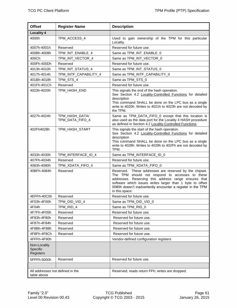
TCG PC Client Platform TPM Profile (PTP) Specification
Family “2.0” TCG Published Page 61 Level 00 Revision 00.43 Copyright © TCG 2003 - 2015 January 26, 2015
Offset Register Name Description
Locality 4
4000h TPM_ACCESS_4 Used to gain ownership of the TPM for this particular Locality.
4007h-4001h Reserved Reserved for future use.
400Bh-4008h TPM_INT_ENABLE_4 Same as TPM_INT_ENABLE_0
400Ch TPM_INT_VECTOR_4 Same as TPM_INT_VECTOR_0
400Fh-400Dh Reserved Reserved for future use.
4013h-4010h TPM_INT_STATUS_4 Same as TPM_INT_STATUS_0
4017h-4014h TPM_INTF_CAPABILITY_4 Same as TPM_INTF_CAPABILITY_0
401Bh-4018h TPM_STS_4 Same as TPM_STS_0
401Fh-401Ch Reserved Reserved for future use.
4023h-4020h TPM_HASH_END This signals the end of the hash operation. See Section 4.2 Locality-Controlled Functions for detailed description This command SHALL be done on the LPC bus as a single write to 4020h. Writes to 4021h to 4023h are not decoded by the TPM.
4027h-4024h TPM_HASH_DATA/ TPM_DATA_FIFO_4
Same as TPM_DATA_FIFO_0 except that this location is also used as the data port for the Locality 4 HASH procedure as defined in Section 4.2 Locality-Controlled Functions.
402Fh4028h TPM_HASH_START This signals the start of the hash operation. See Section 4.2 Locality-Controlled Functions for detailed description This command SHALL be done on the LPC bus as a single write to 4028h. Writes to 4029h to 402Fh are not decoded by TPM.
4033h-4030h TPM_INTERFACE_ID_4 Same as TPM_INTERFACE_ID_0
407Fh-4034h Reserved Reserved for future use.
4083h-4080h TPM_XDATA_FIFO_4 Same as TPM_XDATA_FIFO_0
40BFh-4084h Reserved Reserved. These addresses are reserved by the chipset. The TPM should not respond to accesses to these addresses. Reserving this address range ensures that software which issues writes larger than 1 byte to offset 0080h doesn’t inadvertently encounter a register in the TPM in this space.
4EFFh-40C0h Reserved Reserved for future use.
4F03h-4F00h TPM_DID_VID_4 Same as TPM_DID_VID_0
4F04h TPM_RID_4 Same as TPM_RID_0
4F7Fh-4F05h Reserved Reserved for future use.
4F83h-4F80h Reserved Reserved for future use.
4F87h-4F84h Reserved Reserved for future use.
4F8Bh-4F88h Reserved Reserved for future use.
4F8Fh-4F8Ch Reserved Reserved for future use.
4FFFh-4F90h Vendor-defined configuration registers
Non-Locality Specific Registers
5FFFh-5000h Reserved Reserved for future use.
All addresses not defined in the table above
Reserved, reads return FFh; writes are dropped.

TPM Profile (PTP) Specification TCG PC Client Platform
Page 62 TCG Published Family “2.0” January 26, 2015 Copyright © TCG 2003 - 2015 Level 00 Revision 00.43
Subsequent sections provide implementation details on the defined registers. Note that 1335
registers which are aliased may have multiple versions; e.g., TPM_STS_x represents TPM_STS_0, TPM_STS_1, TPM_STS_2, TPM_STS_3, and TPM_STS_4.
1. The DID/VID, RID, and all the TCG and vendor-specific registers MAY have only one physical copy.
a. If so implemented, these registers SHALL be accessible from any locality. 1340
b. If implemented as separate physical registers, each copy SHALL hold the same data. See Section 6.1 FIFO Interface Locality Usage per Register and Table 39.
2. Handling Command FIFOs
Before issuing a command to the TPM, the software reads the TPM_STS_x register to see if the TPM’s state allows it to accept commands. 1345
Software sends commands to the TPM and reads results from the TPM using a data FIFO. When the TPM_STS_x.burstCount field is > 0, the data FIFO is ready
to accept more data of a command (during a command’s send phase) or return more data from a command (response from a command completion). Since the TPM is not allowed to drop a cycle because of an internal stall, if the TPM 1350
cannot accept a write cycle or respond to a read cycle, it must insert wait states on the bus using the mechanism appropriate to the bus interface, i.e. stall the LPC bus using standard LPC wait syncs or insert one or more SPI wait cycles. See Section 6.4.5 Flow Control, for a detailed description of burstCount.
The FIFO is only a stack of bytes going into and out of the TPM. 1355
TPM_STS_x.burstCount indicates only the depth of the command FIFO, not the direction nor whether the TPM expects more data to be sent or received. TPM_STS_x.Expect and TPM_STS_x.DataAvail fields indicate to the software when the TPM expects more data during a command’s send phase or has more data to be read during a read results phase. 1360
i. The TPM SHALL maintain the TPM_STS_x register so that software can determine whether the TPM is in a state where it can accept commands. The TPM SHALL NOT drop a cycle because of an internal stall. If the TPM cannot accept a write or read cycle, then the TPM SHALL stall the bus using the appropriate method for the bus (standard LPC Wait Syncs or SPI wait 1365
cycles).
5.5.2.2 Completion Command Details
5.5.2.2.1 Command Send
To send a command the software must first set TPM_STS_x.commandReady = 1. Upon receipt of TPM_STS_x.commandReady, the TPM may set TPM_STS_x.Expect = 1 1370
indicating it is ready to receive the command. When the data FIFO is ready to begin receiving the command data, the TPM sets TPM_STS_x.burstCount > 0. The TPM uses TPM_STS_x.burstCount field to throttle the data into the data FIFO.
The TPM keeps TPM_STS_x.Expect = 1 until it receives all the expected data for the command. When the TPM receives all the data for the command (the TPM can 1375
calculate this using the command size parameter which is within the first 10 bytes of the command) it sets TPM_STS_x.Expect = 0 indicating to the software that all data expected has been received.

TCG PC Client Platform TPM Profile (PTP) Specification
Family “2.0” TCG Published Page 63 Level 00 Revision 00.43 Copyright © TCG 2003 - 2015 January 26, 2015
The software signals the TPM to begin executing the command by writing a 1 to the TPM_STS_x_tpmGo field. Upon receipt of TPM_STS_x_tpmGo = 1, the TPM begins 1380
executing the command.
1. Upon receipt of TPM_STS_x.commandReady, the TPM SHALL prepare to receive a command.
2. When ready, the TPM SHALL set TPM_STS_x.commandReady = 1 and the TPM SHALL set TPM_STS_x.burstCount > 0 to indicate to software that it can begin 1385
writing command data to the data FIFO. The TPM MAY set TPM_STS_x.Expect = 1.
3. When the TPM receives the first Byte of the command data, it SHALL set TPM_STS_x.commandReady = 0 and TPM_STS_x.Expect = 1 as an indication to the software that it expects further command data. The TPM SHALL use TPM_STS_x.burstCount to indicate to software whether the data FIFO can accept 1390
more data.
4. The TPM SHALL keep TPM_STS_x.Expect = 1 until it has received all of the data for this command. When the TPM reads the last byte of data from its data FIFO the TPM SHALL set TPM_STS_x.Expect = 0.
5. The TPM MAY ignore TPM_STS_x.tpmGo until TPM_STS_x.Expect is set to 0. 1395
5.5.2.2.2 Data Availability
When a command completes, the TPM puts the results into the data FIFO, which is read via the TPM_DATA_FIFO_x register. Once the TPM has data that can be read, the TPM sets TPM_STS_x.dataAvail = 1 and it remains 1 until all data from the command response are read. After the last byte of the response is read, the TPM sets 1400
TPM_STS_x.dataAvail = 0. The TPM uses TPM_STS_x.burstCount field to throttle the response out of the data FIFO.
After sending a command, the software reads the TPM_STS_x.dataAvail register to see if the response from the TPM is available, indicating a command has completed. If the TPM_STS_x.dataAvail field is 1, at least 1 byte of the command response data is 1405
available.
1. Upon completing a command the TPM SHALL place the command’s response data into the data FIFO.
2. The TPM SHALL set TPM_STS_x.dataAvail = 1 as an indication to the software that the command has completed and data is available to be read from the data FIFO. 1410
When the last byte of the response data is read from the data FIFO the TPM SHALL set TPM_STS_x.dataAvail = 0.
Note: A value of 1 only indicates that there is at least one byte in the data FIFO; it is not an indicator that the data can be read from the data FIFO. I.e., this is not
the final indicator to software that it can begin reading from the data FIFO. 1415
Software must also wait until TPM_STS_x.burstCount > 0, see below.
3. The TPM SHALL set TPM_STS_x.burstCount > 0 to indicate to software that it can begin reading the response data from the data FIFO. Once the software has started to read the response from the data FIFO, the TPM SHALL use TPM_STS_x.burstCount as an indicator to software that data is available in the 1420
data FIFO.

TPM Profile (PTP) Specification TCG PC Client Platform
Page 64 TCG Published Family “2.0” January 26, 2015 Copyright © TCG 2003 - 2015 Level 00 Revision 00.43
5.5.2.3 Interface Specific Aborts
5.5.2.3.1 Command Aborts
There are several ways to cause a TPM to abort an executing command: TPM_ACCESS_x.Seize, TPM_STS_x.commandReady, and 1425
TPM_ACCESS_x.activeLocality. Because of implementation differences and the non-deterministic nature of some commands that may be executing, the TPM may not be able to respond to a command abort immediately or within a predictable time. This non-deterministic behavior causes driver design difficulties because the driver will not be able to distinguish between a TPM waiting normally and a TPM that has 1430
encountered an error and is not responsive. Therefore, a maximum amount of time is specified so TPM manufacturers have a design parameter that drivers can rely upon.
The TPM’s internal state after an abort may be set to the state of the TPM prior to the aborted command or to the state it would have entered after completing the aborted command. 1435
The purpose for a command abort when setting TPM_ACCESS_x.SEIZE or x.activeLocality is that the TPM cannot be allowed to “leak” information between localities. In other words, the response to a command sent from one locality cannot be returned to another locality.
Note: Because there is no requirement for a TPM to handle more than one operation 1440
at a time, there can be no actual and standardized TPM command to cause an abort. The method for signaling an abort to the TPM is by writing to specific registers.
1. Upon a successful command abort, the TPM SHALL stop the currently executing command, clear the FIFOs, and transition to idle state.
2. The following operations SHALL cause a command abort: 1445
a. Writing a 1 to TPM_STS_x.commandReady during the execution of a command.
b. Writing a 1 to TPM_STS_x.commandReady during the receipt of a command but before execution of a command.
c. Writing a 1 to TPM_ACCESS_x.Seize ,but only when successful.
d. Writing a 1 to TPM_ACCESS_x.activeLocality. 1450
e. Successful completion of the HASH_START per Section 4.2, Locality-Controlled Functions.
3. The TPM internal state MAY either be in the pre-aborted command or post-aborted command state and SHALL not be in any intermediate state.
4. For commands indicated as short or medium duration (i.e., those that do not cause 1455
key generation), the TPM SHALL respond to an abort within TIMEOUT_A. For commands indicated as long duration or those that cause key generation, the TPM SHALL respond to a request to abort the command within TIMEOUT B.

TCG PC Client Platform TPM Profile (PTP) Specification
Family “2.0” TCG Published Page 65 Level 00 Revision 00.43 Copyright © TCG 2003 - 2015 January 26, 2015
5.5.2.4 Access Register
The purpose of this register is to allow the processes operating at the various localities 1460
to share the TPM. The basic notion is that any locality can request access to the TPM by setting the TPM_ACCESS_x.requestUse field using its assigned TPM_ACCESS_x register address. If there is no currently set locality, the TPM sets current locality to the requesting one and allows operations only from that locality. If the TPM is currently at another locality, the TPM keeps the request pending until the currently 1465
executing locality frees the TPM. Software relinquishes the TPM’s locality by writing a 1 to the TPM_ACCESS_x.activeLocality field. Upon release, the TPM honors the highest locality request pending. If there is no pending request, the TPM enters the “free” state.
There may be circumstances where the access to the TPM is “held” by either crashed 1470
or ill-behaved software. For this reason, the TPM_ACCESS_x.Seize field may be used. It is generally assumed that software executing at higher level localities is more
trusted and less prone to crashing and better behaved at relinquishing the TPM. The TPM_ACCESS_x.Seize field allows higher-level localities to gain control of the TPM. This method, however, should be the exception rather than the common method for 1475
gaining access to the TPM.
In TPM 1.2, the relationship between the internal flag TPM_PERMANENT_FLAGS->tpmEstablished and the interface field TPM_ACCESS_x.tpmEstablishment is inverted logic. Therefore, when one is FALSE the other is TRUE. This is because software accesses the TPM_PERMANENT_FLAGS->tpmEstablished field and expects "positive" 1480
logic, while hardware reads the TPM_ACCESS_x.tpmEstablishment and expects negative logic. To maintain some minimum level of backwards compatibility, the definition of the interface field TPM_ACCESS_x.tpmEstablishment maintains the same logic as in a TPM 1.2. TPM 2.0 does not have a flag that corresponds to the TPM_PERMANENT_FLAGs->tpmEstablished nor a command to reset the 1485
TPM_ACCESS_x.tpmEstablishment field, so an interface method has been added to this definition of the FIFO interface to provide the same functionality for a TPM 2.0
Software writing to the TPM_ACCESS_x register should set only one field to a 1 for each write. If a write to this register contains more than one field set to 1, the behavior of this register is undefined in this specification and the behavior between TPM 1490
implementations may differ.
Software needs to consider that there is no timeout condition defined for the period between the release of one locality until the access to a subsequent locality is granted (i.e. TPM_ACCESS_x.activeLocality is set to 1), as this process happens practically immediately from a Software point of view. 1495
Note: The HASH_START/_DATA/_END sequence is independent of the Access register. Software does not need to use the Access Register to send
HASH_START/_DATA/_END, because those commands assert Locality 4. As a result, the TPM must always be ready to accept these commands when there is no active locality. 1500
1. The TPM SHALL implement the TPM_ACCESS_x register as documented in Table 18.
2. Any write operation to the TPM_ACCESS_x register with more than one field set to a 1 MAY be treated as vendor specific.
3. For each write, fields containing a 0 SHALL be ignored. 1505

TPM Profile (PTP) Specification TCG PC Client Platform
Page 66 TCG Published Family “2.0” January 26, 2015 Copyright © TCG 2003 - 2015 Level 00 Revision 00.43
Table 18 — Access Register
Abbreviation: TPM_ACCESS_x
General Description: Used to gain ownership of the TPM
Bit Descriptions:
7 Read Only
tpmRegValidSts Default: 0 This bit indicates whether all other bits of this register contain valid values, if it is a 1.
6 Read
Only
Reserved Default: 0 SHALL return 0
5 Read/
Write
activeLocality Default: 0 Read 0 = This locality is not active.
Read 1 = This locality is active.
Write 1 = Relinquish control of this locality
4 Read/ Write
beenSeized Default: 0 Read 0 = This locality operates normally or is not active
Read 1 = Control of the TPM has been taken from this locality by another higher locality while this locality had its TPM_ACCESS_x.activeLocality bit set.
Write 1 = Clear this bit.
3 Write
Only
Seize Reads always return 0
A write to this field forces the TPM to give control of the TPM to the locality setting this bit if it is the higher priority locality.
2 Read
Only
pendingRequest Default: 0 Read 1 = some other locality is requesting usage of the TPM
Read 0 = no other locality is requesting use of the TPM
1 Read/
Write
requestUse Default: 0 Read 0 = This locality is either not requesting to use the TPM or is already the active locality
Read 1 = This locality is requesting to use TPM and is not yet the active locality
Write 1 = Request that this locality is granted the active locality
0 Read
Only
tpmEstablishment
Default: 1 There are some special end cases (e.g., error conditions) where software needs to know if a Dynamic OS has previously been established on this platform. This bit performs this function. The value of this flag SHALL be preserved across power and reset cycles.
Read 0 = A Dynamic OS has been previously established on this platform
Read 1 = A Dynamic OS has not been previously established on this platform
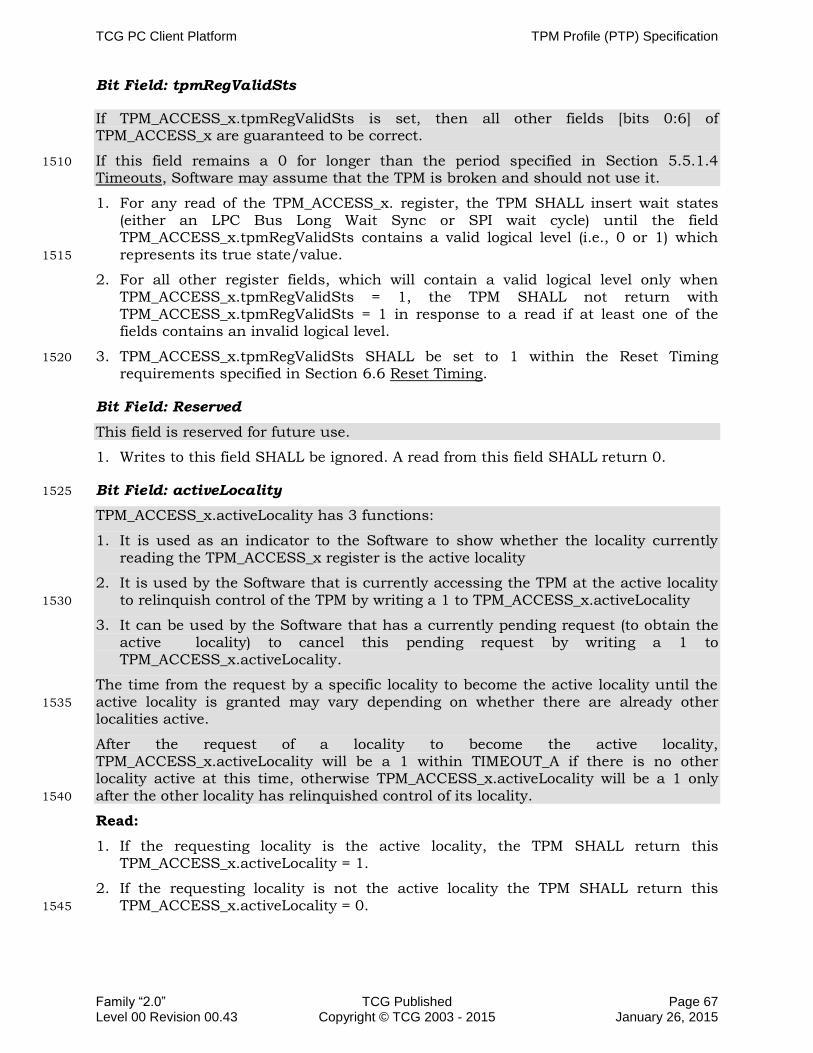
TCG PC Client Platform TPM Profile (PTP) Specification
Family “2.0” TCG Published Page 67 Level 00 Revision 00.43 Copyright © TCG 2003 - 2015 January 26, 2015
Bit Field: tpmRegValidSts
If TPM_ACCESS_x.tpmRegValidSts is set, then all other fields [bits 0:6] of TPM_ACCESS_x are guaranteed to be correct.
If this field remains a 0 for longer than the period specified in Section 5.5.1.4 1510
Timeouts, Software may assume that the TPM is broken and should not use it.
1. For any read of the TPM_ACCESS_x. register, the TPM SHALL insert wait states (either an LPC Bus Long Wait Sync or SPI wait cycle) until the field TPM_ACCESS_x.tpmRegValidSts contains a valid logical level (i.e., 0 or 1) which represents its true state/value. 1515
2. For all other register fields, which will contain a valid logical level only when TPM_ACCESS_x.tpmRegValidSts = 1, the TPM SHALL not return with TPM_ACCESS_x.tpmRegValidSts = 1 in response to a read if at least one of the fields contains an invalid logical level.
3. TPM_ACCESS_x.tpmRegValidSts SHALL be set to 1 within the Reset Timing 1520
requirements specified in Section 6.6 Reset Timing.
Bit Field: Reserved
This field is reserved for future use.
1. Writes to this field SHALL be ignored. A read from this field SHALL return 0.
Bit Field: activeLocality 1525
TPM_ACCESS_x.activeLocality has 3 functions:
1. It is used as an indicator to the Software to show whether the locality currently reading the TPM_ACCESS_x register is the active locality
2. It is used by the Software that is currently accessing the TPM at the active locality to relinquish control of the TPM by writing a 1 to TPM_ACCESS_x.activeLocality 1530
3. It can be used by the Software that has a currently pending request (to obtain the active locality) to cancel this pending request by writing a 1 to TPM_ACCESS_x.activeLocality.
The time from the request by a specific locality to become the active locality until the active locality is granted may vary depending on whether there are already other 1535
localities active.
After the request of a locality to become the active locality, TPM_ACCESS_x.activeLocality will be a 1 within TIMEOUT_A if there is no other locality active at this time, otherwise TPM_ACCESS_x.activeLocality will be a 1 only after the other locality has relinquished control of its locality. 1540
Read:
1. If the requesting locality is the active locality, the TPM SHALL return this TPM_ACCESS_x.activeLocality = 1.
2. If the requesting locality is not the active locality the TPM SHALL return this TPM_ACCESS_x.activeLocality = 0. 1545

TPM Profile (PTP) Specification TCG PC Client Platform
Page 68 TCG Published Family “2.0” January 26, 2015 Copyright © TCG 2003 - 2015 Level 00 Revision 00.43
Write:
1. If a write occurs at the current active locality:
a. On a write of a 1 to the active locality’s TPM_ACCESS_x.activeLocality field the TPM SHALL:
i. Clear TPM_ACCESS_x.activeLocality field to 0 for the current locality. 1550
ii. Relinquish control of the TPM for the current locality.
b. If there are pending requests from other localities, the TPM SHALL transfer control to the locality with the highest priority and set TPM_ACCESS_x.activeLocality to 1 for the new active locality.
Note: This locality becomes the new active locality. 1555
2. If a write of 1 to TPM_ACCESS_x.activeLocality occurs at a locality which is not the current active locality and the locality performing the write has its TPM_ACCESS_x.requestUse set to 1 (e.g., there is a pending request for this locality which has not been granted), the TPM SHALL cancel the pending request from this locality. 1560
3. If the requesting locality is not the active locality and its TPM_ACCESS_x.requestUse is 0, a write to this TPM_ACCESS_x.activeLocality SHALL be ignored.
4. TPM_ACCESS_x.activeLocality SHALL be set to 1 within TIMEOUT_A after TPM_ACCESS_x.requestUse has been set to 1 if the TPM is in the "free" state. 1565
5. If there is another locality active at the time when a subsequent locality sets its TPM_ACCESS_x.requestUse field to 1, this TPM_ACCESS_x.activeLocality SHALL be set to 1 within TIMEOUT_A after the other locality has relinquished control of its locality.
For the handling of changing locality during command execution and aborts see 1570
Section 5.5.1.1 Bus Aborts
For example if Locality 2 is the current active locality and Locality 0 sets TPM_ACCESS_0.requestUse = 1, then Locality 0 has a pending request (i.e. TPM_ACCESS_0.requestUse is 1) and all other localities (1 to 4) have TPM_ACCESS_x.pendingRequest set to 1. 1575
If now Locality 3 sets TPM_ACCESS_3.requestUse = 1 now Locality 3 also has a pending request with TPM_ACCESS_0.requestUse and TPM_ACCESS_3.requestUse being 1 and all other localities (0, 1, 2, 3 and 4) having TPM_ACCESS_x.pendingRequest set to 1.
Now Localities 0, 1, 2, 3, and 4 have TPM_ACCESS_x.pendingRequest set to 1 and 1580
localities 0 and 3 have their TPM_ACCESS_x.requestUse set to 1.
As soon as Locality 2 relinquishes control of the TPM by setting TPM_ACCESS_x.activeLocality to a 1, the TPM automatically transfers the control of the TPM to Locality 3 (because of the locality priority rules) and the pending request remains for Locality 0. 1585
Now localities 1 to 4 have their TPM_ACCESS_x.pendingRequest set to 1 and Locality 0 has TPM_ACCESS_0.requestUse set to 1.

TCG PC Client Platform TPM Profile (PTP) Specification
Family “2.0” TCG Published Page 69 Level 00 Revision 00.43 Copyright © TCG 2003 - 2015 January 26, 2015
If now Locality 0 decides not to maintain the request to use the TPM, it sets TPM_ACCESS_0.activeLocality = 1 and consequently TPM_ACCESS_0.requestUse is cleared to 0 and TPM_ACCESS_x.pendingRequest of the localities 1 to 4 are cleared to 1590
0 as well.
Bit Field: beenSeized
If a locality is the active locality, Software can use this field to determine whether the active locality has been taken away (i.e. seized) by another, higher priority locality and therefore the seized locality needs to abort an entire task and restart it after it has 1595
obtained the active locality again. This field can be cleared by the seized locality.
1. TPM_ACCESS_x.beenSeized SHALL be set to a 1 when the active locality gets seized.
2. A write of a 1 to TPM_ACCESS_x.beenSeized SHALL clear this field to a 0.
Bit Field: Seize 1600
The seize operation is a mechanism as a "last line of defense", if rogue Software does not relinquish control of a TPM and another, higher locality needs to obtain control of the TPM.
In this case, the Software of the higher locality (i.e. seizing locality) sets the TPM_ACCESS_x.Seize field to a 1 and then polls on TPM_ACCESS_x.activeLocality 1605
until this field returns a 1 (i.e. successful seize operation). At this point, the Software operating at the lower locality will be informed about the successful seize operation by TPM_ACCESS_x.beenSeized being set to a 1.
After the successful seize operation, the Software of the seizing locality reads the TPM_STS_x.commandReady field: 1610
1. If the TPM_STS_x.commandReady field is a 0, software should write a 1 to the field and then poll until it becomes a 1,
2. If the TPM_STS_x.commandReady field is set and TPM_STS_x.burstCount > 0, software may immediately write the command to the TPM.
Seize operations from Locality 0 are ignored by the TPM, unless the TPM is in Locality 1615
None, since this operation has no real meaning for Locality 0.
For example, if Locality 0 is the currently active locality and Locality 1 writes a 1 to TPM_ACCESS_1.Seize, the TPM must clear the TPM_ACCESS_0.activeLocality field of locality 0, i.e. remove control of the TPM from Locality 0 and set TPM_ACCESS_x.beenSeized to 1. Consequently, the TPM must abort any currently 1620
executing command and stop accepting commands from Locality 0 as Locality 0 no longer has control of the TPM.
1. If the write to TPM_ACCESS_x.Seize occurs from a locality of higher priority than the current locality:
a. The TPM SHALL clear the TPM_ACCESS_x.activeLocality fields for any active 1625
locality of lower priority than the locality seizing the TPM.
b. The TPM SHALL NOT change the state of the TPM_ACCESS_x.requestUse field for any locality except the one writing this field.

TPM Profile (PTP) Specification TCG PC Client Platform
Page 70 TCG Published Family “2.0” January 26, 2015 Copyright © TCG 2003 - 2015 Level 00 Revision 00.43
c. The TPM SHALL set TPM_ACCESS_x.activeLocality to a 1, clear the TPM_ACCESS_x.requestUse field to a 0 for the locality writing this field, and, if 1630
there are no other active requests, clear the TPM_ACCESS_x.pendingRequest field to 0 for all other localities.
d. The TPM SHALL abort any command that is currently in process, as defined in Section 5.5.2.3.1 Command Aborts.
2. If the write occurs from a locality that is equal to or lower than the current locality 1635
the TPM SHALL ignore the write.
3. A read to TPM_ACCESS_x.Seize SHALL return 0.
Bit Field: pendingRequest
This field indicates whether a locality other than the currently active locality has requested to become the active locality. Software can use this field to determine if it 1640
should relinquish control of the TPM so that the other locality can use it.
1. When a locality writes a 1 to its TPM_ACCESS_x.requestUse, the TPM SHALL set TPM_ACCESS_x.pendingRequest to a 1 for all other localities.
2. If there are no pending requests, when the locality that has written a 1 to TPM_ACCESS_x.requestUse has obtained the control of the TPM as signified by 1645
TPM_ACCESS_x.activeLocality, TPM_ACCESS_x.pendingRequest for all other localities SHALL be cleared to 0.
3. When the locality with a pending request writes a 1 to its TPM_ACCESS_x.activeLocality field (i.e. cancels the pending request):
a. If there are no other pending requests, the TPM SHALL clear all 1650
TPM_ACCESS_x.pendingRequest field to 0.
b. If there is one other pending request, the TPM SHALL clear the TPM_ACCESS_x.pendingRequest field to 0 for the locality with the active request.
c. If there are multiple pending requests, the TPM SHALL NOT clear any 1655
TPM_ACCESS_x.pendingRequest field to 0.
4. The TPM SHALL ignore writes to this field.
Bit Field: requestUse
This field is used to request access to the TPM as the active locality. Software can write a 1 to this field when it needs to get control of the TPM. After the request is 1660
issued, Software must wait until its request to become the active locality is granted.
This field may only be cleared by writing a 1 to TPM_ACCESS_x.activeLocality for the requesting locality.
Note: Writing a zero to TPM_ACCESS_x.requestUse does not clear the pending request for this locality. See bit field: activeLocality for more information. 1665
1. When a locality writes a 1 to TPM_ACCESS_x.requestUse, the TPM SHALL set this field to 1 for the requesting locality.
Note: If the TPM_ACCESS_x.requestUse is already set to 1, the TPM SHALL ignore writes of 1 to this field.

TCG PC Client Platform TPM Profile (PTP) Specification
Family “2.0” TCG Published Page 71 Level 00 Revision 00.43 Copyright © TCG 2003 - 2015 January 26, 2015
2. When the locality that has set its TPM_ACCESS_x.requestUse has been granted 1670
control of the TPM as signified by TPM_ACCESS_x.activeLocality set to 1, the TPM SHALL clear the TPM_ACCESS_x.requestUse field to 0 for the requesting locality.
3. When a locality cancels a pending request, signified by writing a 1 to TPM_ACCESS_x.activeLocality, the TPM SHALL clear this field to 0 for the requesting locality. 1675
4. The TPM SHALL ignore writes of 0 to TPM_ACCESS_x.requestUse.
Bit Field: tpmEstablishment
TPM_ACCESS_x.tpmEstablishment is a register field which indicates whether a Dynamic OS has been launched. The reason this register field uses inverted logic is to allow systems without TPMs to indicate, using this register, that no Dynamical OS has 1680
been launched. Since the default state of the register field is 1, Reading from a device that doesn’t exist (there is no device to claim the read request) returns a value of all
ones, therefore a read access to the TPM’s access register when there is no TPM present returns as if no Dynamic OS has been established.
1. If the TPM_ACCESS_x.tpmRegValidSts is set to 1, any read of the 1685
TPM_ACCESS_x.tpmEstablishment field SHALL reflect the correct value.
2. If TPM_ACCESS_x.tpmRegValidSts is cleared to 0 (i.e., TPM_ACCESS register is not valid):
a. TPM_ACCESS_x.tpmEstablishment MAY be a 0.
b. TPM_ACCESS_x.tpmEstablishment SHALL NOT be a 1 unless that is the 1690
correct value of the field.
3. TPM_ACCESS_x.tpmEstablishment SHALL be 0 prior to initialization and update of the DRTM PCR at the completion of HASH_END.
a. If TPM_ACCESS_x.tpmEstablishment is 0:
i. TPM_ACCESS_x.tpmEstablishment SHALL remain 0 until the TPM receives 1695
a write of 1 to TPM_STS_x.resetEstablishmentBit
ii. The value of TPM_ACCESS_x.tpmEstablishment SHALL NOT change across power or reset cycles.
4. TPM_ACCESS_x.tpmEstablishment SHALL be 1 if no DRTM HASH_END has been executed. 1700
5. If TPM_ACCESS_x.tpmEstablishment is 1, receipt of a DRTM HASH_END command SHALL clear it to 0 within TIMEOUT_A.
6. TPM_ACCESS_x.tpmEstablishment SHALL be duplicated across Localities 0-4.

TPM Profile (PTP) Specification TCG PC Client Platform
Page 72 TCG Published Family “2.0” January 26, 2015 Copyright © TCG 2003 - 2015 Level 00 Revision 00.43
5.5.2.5 Status Register
The TPM_STS_x.commandReady field is functionally overloaded. If there is no 1705
command being executed, a write to this field is an indicator to the TPM that it must prepare to receive a command. If there is a command being executed, a write to this field serves as an abort of that command. If a command has completed and the results have been read, a write to this field allows the TPM to free internal resources (including the Read and Write FIFOs) and proceed with background or other processes 1710
allowed during idle time. A TPM may be designed in a manner that allows the first write to this field to clear and free the TPM’s resources and make it ready to receive a command.
Software must be prepared to send two writes of a 1 to this field: the first to indicate successful read of all the data, thus clearing the data from the ReadFIFO and freeing 1715
the TPM’s resources, and the second to indicate to the TPM it is about to send a new command. The time between receiving the data from a command and sending the first
write to this field should be very short to allow TPMs that perform background processing to proceed. The time between the first write and the second indicates the beginning of a new command is arbitrary. 1720
Software may be written such that the second write to this field is only necessary if the TPM does not respond with a ready after the first write. In this case, the software, after writing a 1 to this field indicating the receipt of the data, may query this field. If the TPM sets this field to a 1 indicating its readiness to receive a command, the software may proceed to send the command without writing a 1 to this field. 1725
5.5.2.5.1 TPM Status Register States
For each write to this register, there SHALL be only one field set to a 1. If the TPM receives a write with more than one field set, the TPM SHALL ignore the entire cycle. For each write, fields containing 0 are ignored.
The TPM is considered to be in one of the following defined states: 1730
1. Command Reception occurs between the write of the first byte of a command to the WriteFIFO following a ready state and the receipt of a write of 1 to TPM_STS_x.tpmGo.
2. Command Execution occurs after receipt of a 1 to TPM_STS_x.tpmGo and the TPM setting TPM_STS_x.commandReady:dataAvail to a 1, unless the command is 1735
aborted as defined in Section 5.5.2.3.1 Command Aborts.
3. Command Completion occurs after completion of a command (indicated by the TPM setting the TPM_STS_x.commandReady:dataAvail to a 1 and before a write of a 1 by the software to TPM_STS_x.commandReady).
4. Idle is any time after Command Completion followed by the write of a 1 by the 1740
software to TPM_STS_x.commandReady, following locality change, or a command abort. Idle is the initial state of TPM upon completion of _TPM_INIT.
5. Ready is any time the TPM is ready to receive a command, as indicated by TPM_STS_x.commandReady being set.

TCG PC Client Platform TPM Profile (PTP) Specification
Family “2.0” TCG Published Page 73 Level 00 Revision 00.43 Copyright © TCG 2003 - 2015 January 26, 2015
The following informative diagram is derived from the above normative statements. It 1745
is informative and only for illustrating diagrammatically the above TPM states and their transitions. The numbers in parentheses reference the states represented by row numbers in Table 22 — State Transition Table
Command Reception
Command Execution
Command Completion
Idle
Ready
(37) Write 1 to commandReady
(3) Write 1 to commandReady
(9) Write 1st byte to write FIFO
(18) Write 1 to tpmGo
(22) Command Completes
(7) Write 1 to commandReady
(0B) TPM may go directly to Ready
Recover from Abort
TPM_Init
(0A) Remain IdleMust do so < TIMEOUT_B
only if time since entering Idle
< TIMEOUT_B
Figure 3 — State Transition Diagram
1750

TPM Profile (PTP) Specification TCG PC Client Platform
Page 74 TCG Published Family “2.0” January 26, 2015 Copyright © TCG 2003 - 2015 Level 00 Revision 00.43
5.5.2.5.2 Bus Access of the Status Register
1. For any read from the TPM_STS_x. register, the TPM SHALL assert zero or more wait states (either an LPC Bus Long Wait Sync or SPI wait cycles) until all fields in the register, except TPM_STS_x.dataAvail and TPM_STS_x.Expect, contain a valid logical level (i.e., 0 or 1) which represents their true state/value. 1755
2. For the register fields TPM_STS_x.dataAvail and TPM_STS_x.Expect, which will contain a valid logical level only when TPM_STS_x.stsValid=1, the TPM SHALL not return with TPM_STS_x.stsValid=1 in response to a read if either TPM_STS_x.dataAvail (while reading results) or TPM_STS_x.Expect (while sending a command) contains an invalid logical level, respectively. 1760
3. The TPM SHALL implement the Status Register as documented in Section 5.5.2.5 Status Register.
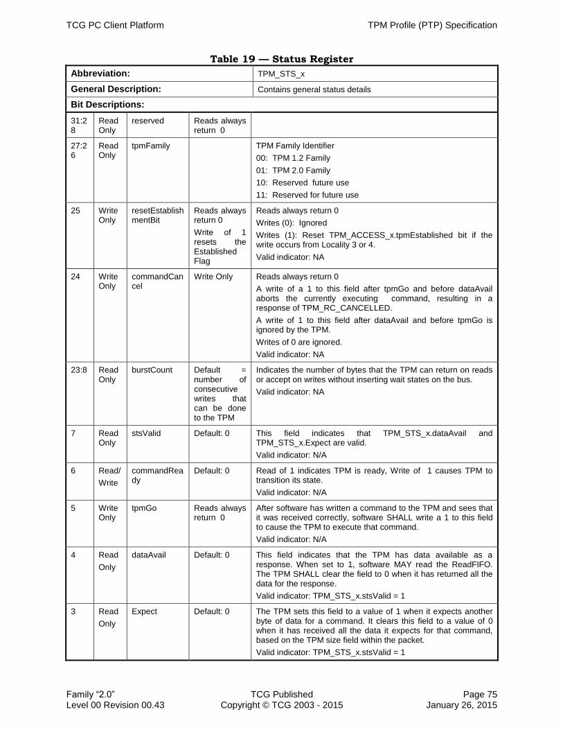
TCG PC Client Platform TPM Profile (PTP) Specification
Family “2.0” TCG Published Page 75 Level 00 Revision 00.43 Copyright © TCG 2003 - 2015 January 26, 2015
Table 19 — Status Register
Abbreviation: TPM_STS_x
General Description: Contains general status details
Bit Descriptions:
31:28
Read Only
reserved Reads always return 0
27:26
Read Only
tpmFamily TPM Family Identifier
00: TPM 1.2 Family
01: TPM 2.0 Family
10: Reserved future use
11: Reserved for future use
25 Write Only
resetEstablishmentBit
Reads always return 0
Write of 1 resets the Established Flag
Reads always return 0
Writes (0): Ignored
Writes (1): Reset TPM_ACCESS_x.tpmEstablished bit if the write occurs from Locality 3 or 4.
Valid indicator: NA
24 Write Only
commandCancel
Write Only Reads always return 0
A write of a 1 to this field after tpmGo and before dataAvail aborts the currently executing command, resulting in a response of TPM_RC_CANCELLED.
A write of 1 to this field after dataAvail and before tpmGo is ignored by the TPM.
Writes of 0 are ignored.
Valid indicator: NA
23:8 Read Only
burstCount Default = number of consecutive writes that can be done to the TPM
Indicates the number of bytes that the TPM can return on reads or accept on writes without inserting wait states on the bus.
Valid indicator: NA
7 Read Only
stsValid Default: 0 This field indicates that TPM_STS_x.dataAvail and TPM_STS_x.Expect are valid.
Valid indicator: N/A
6 Read/
Write
commandReady
Default: 0 Read of 1 indicates TPM is ready, Write of 1 causes TPM to transition its state.
Valid indicator: N/A
5 Write Only
tpmGo
Reads always return 0
After software has written a command to the TPM and sees that it was received correctly, software SHALL write a 1 to this field to cause the TPM to execute that command.
Valid indicator: N/A
4 Read
Only
dataAvail
Default: 0 This field indicates that the TPM has data available as a response. When set to 1, software MAY read the ReadFIFO. The TPM SHALL clear the field to 0 when it has returned all the data for the response.
Valid indicator: TPM_STS_x.stsValid = 1
3 Read
Only
Expect
Default: 0 The TPM sets this field to a value of 1 when it expects another byte of data for a command. It clears this field to a value of 0 when it has received all the data it expects for that command, based on the TPM size field within the packet.
Valid indicator: TPM_STS_x.stsValid = 1

TPM Profile (PTP) Specification TCG PC Client Platform
Page 76 TCG Published Family “2.0” January 26, 2015 Copyright © TCG 2003 - 2015 Level 00 Revision 00.43
Abbreviation: TPM_STS_x
General Description: Contains general status details
Bit Descriptions:
2 Read Only
selfTestDone
Default: 0 This field indicates that the TPM has completed all self-test actions following a TPM_ContinueSelfTest command. Read of 0 indicates self-test is not complete. Read of 1 indicates self-test is complete.
1 Write Only
responseRetry
Reads always return 0
Software writes a 1 to this field to force the TPM to re-send the response.
Reads SHALL return 0
Valid indicator: N/A
0 Read
Only
Reserved (0) Reads always return 0
Bit Field: resetEstablishmentBit
This field is used to replace functionality provided by the TSC_ResetEstablishmentBit 1765
command in TPM 1.2. This command is not present in TPM 2.0, but this interface mechanism provides equivalent functionality.
This field is used to reset the state of the TPM_ACCESS_x.tpmEstablished field, once that bit has been set to 0 by a D-RTM sequence. A write to this field will be processed by the TPM as if a command has been received. Once this field is written, the TPM will 1770
clear commandReady until the TPM_ACCESS_x.tpmEstablished flag has been cleared.
This field can only be written from Localities 3 and 4.
The TPM will treat a write to this bit as if the TPM has received a Command, and will set TPM_STS_x.dataAvail to 1 once the actions of the operation have been completed. As the TPM may or may not place data in the FIFO, software should ignore this data. 1775
It will be overwritten in the next command cycle.
1. Reads to TPM_STS_x.resetEstablishmentBit SHALL always return 0.
2. For Localities 0-2, writes are ignored.
3. For Localities 3 and 4
a. Writes of 0 are ignored 1780
b. When in the Ready state, writes of 1 set TPM_ACCESS_x.tpmEstablished bit to a 1 and clear TPM_STS_x.resetEstablishmentBit bit to 0 within TIMEOUT_A.
Bit Field: commandCancel
Cancel may be used by software to request the TPM to terminate processing the
current command. Software might request this because the system is going to a lower 1785
power state. The TPM will either complete the currently processing command and return the result, or will cancel the command and return the return code TPM_RC_Canceled. In general, for long running commands, the TPM may have checkpoints in its code to check the state of the Cancel field. If, at one of these checkpoints, the TPM sees a Command Cancel request, the TPM has the option of 1790
canceling the command or completing the command. TPM’s are not required to perform this check. TPM’s that can finish all commands within the required timeouts may return the command response instead of cancelling the command.

TCG PC Client Platform TPM Profile (PTP) Specification
Family “2.0” TCG Published Page 77 Level 00 Revision 00.43 Copyright © TCG 2003 - 2015 January 26, 2015
Cancel is an asynchronous input. Driver writers should take care in use of this function in their drivers, as the TPM could enter a state where it would process no 1795
commands. This case occurs if SW sends a Cancel, but fails to clear it. The TPM would cancel or complete the command and transition to Command Completion with a result. If SW completes that transaction and starts a new transaction without clearing Cancel, the TPM will check Cancel during Command Execution and likely cancel the next command as well. Driver writers should take care to send Command Cancel 1800
requests only when the TPM is in Command Execution state and to only clear the field when the TPM has exited Command Execution to avoid unexpected behavior.
1. When the TPM is in the Command Execution state and TPM_STS_x.commandCancel is set to 1:
a. The TPM MAY terminate command processing, 1805
b. The TPM SHALL return a response and transition to the Command Completion state:
i. If the command is successfully completed, the TPM SHALL return the command response.
ii. If the command is terminated, the TPM SHALL return TPM_RC_CANCELED. 1810
iii. The TPM SHALL complete the command or cancel it within TIMEOUT_B.
2. When the TPM is in any state other than Command Execution, the TPM SHOULD ignore TPM_STS_x.commandCancel.
Bit Field: BurstCount:
It's helpful to understand burstCount by first explaining it in the context of an 1815
example implementation. For example, a TPM's firmware processes commands once they are received by the TPM. Software however, does not directly interact with the TPM's firmware. Rather, it sends and receives data via hardware registers called a data FIFO. During a command send phase, software writes command data directly to the data FIFO which the firmware reads from the FIFO. There is no relationship between 1820
the size or amount of data sent to the data FIFO (from either side) and the size of the command or the command’s response. The data FIFO, therefore, can be thought of as a hardware buffer between the software and the TPM's firmware. The value in the burstCount field is simply the number of bytes that can be written or read from the data FIFO (i.e., the hardware buffer) at any one time. It will likely require multiple 1825
writes (for command send) or multiple reads (for response reads) to and from the data FIFO in order to send a command and read a response.
It is expected that the data FIFO is sufficiently fast so that, provided there is room (during command send) and bytes available (during a read response) in the data FIFO, all writes and reads will occur without any wait states. Therefore, burstCount is 1830
defined as the number of bytes that can be written to or read from the data FIFO by the software without incurring a wait state.
Software should read this field and write or read the number of bytes indicated. Once that number of bytes has been written to the TPM, the TPM may set burstCount = 0. Software must wait while burstCount = 0, by polling on burstCount, until the TPM 1835
sets burstCount > 0. Once burstCount > 0 software resumes writing or reading data up to the new burstCount value.

TPM Profile (PTP) Specification TCG PC Client Platform
Page 78 TCG Published Family “2.0” January 26, 2015 Copyright © TCG 2003 - 2015 Level 00 Revision 00.43
Again, there is no relationship between the size of the data FIFO and the value in the burstCount field, versus the size of the command or response data. On a command send, software must not pad to the data FIFO nor must it read more response data 1840
than indicated by the command’s response size value. For example, if after sending several data FIFO's worth of command data to the TPM, there are seven bytes left to send, even if burstCount = 16, software must still only send seven bytes. Conversely, on response read if there are only three bytes left of the response to read, software must only read three bytes from the data FIFO even if burstCount = 16. 1845
This field may be dynamic or static as indicated by TPM_INTF_CAPABILITY_x.burstCountStatic.
A dynamic burstCount field reports a changing number of bytes that can be read or written. For example, on command send, as data is written to the data FIFO the burstCount field is decremented by the number of bytes written indicating there are 1850
fewer bytes available to write into the data FIFO. As the firmware reads the data out of the data FIFO the burstCount field is incremented indicating there are more bytes available in the FIFO. Conversely, on response read, as software reads data from the data FIFO the burstCount field decrements indicating there are fewer bytes in the data FIFO available to read without incurring a wait state. As firmware writes response 1855
data to the data FIFO the burstCount field increments indicating there are more bytes available to read without incurring a wait state.
A static burstCount field reports a fixed number of bytes that can be read or written. Software reads burstCount and must keep track of that value. Once software begins to write, for command send, or read, for response read, the TPM sets burstCount = 0 1860
until the fixed value is written or read. Only after the fixed number of bytes have been written or read will the burstCount field contain a nonzero value for software to read. Note that in this case, burstCount is a fixed value from _TPM_INIT, allowing software to read burstCount once when the software is first initialized and to save the value, and to use the saved value until the next _TPM_INIT. In this case after the initial read 1865
of burstCount, software only needs to look at whether burstCount is a zero or non-zero value.
Note: It takes roughly 330 ns per byte transfer on LPC. 256 bytes would take 84 us. Chipsets may not be designed to post this much data to LPC; therefore, the CPU itself is stalled for much of this time. Sending 1 kB would take 350 us. Therefore, even if 1870
the TPM_STS_x.burstCount field is a high value, software should be interruptible during this period. For SPI, assuming 20MHz clock and 64-byte transfers, it would take about 120 usec to move 256B of data. Sending 1kB would take about 500 usec. If the transactions are done using 4 bytes at a time, then it would take about 1 msec. to transfer 1kB of data. 1875
1. For dynamic burstCount (I.e., TPM_INTF_CAPABILITY_x.burstCountStatic == 0):
a. For command send phase
i. If the data FIFO is not ready to receive data from the software without incurring an LPC wait state, the TPM SHALL set burstCount = 0.
Note: this rule applies not just to the beginning of the command send phase 1880
but at any time during the command send phase. E.g., after several writes to the data FIFO have occurred the software may fill the data FIFO completely because the firmware cannot read and process the data as fast as software can write it.

TCG PC Client Platform TPM Profile (PTP) Specification
Family “2.0” TCG Published Page 79 Level 00 Revision 00.43 Copyright © TCG 2003 - 2015 January 26, 2015
ii. When the TPM is ready to receive data in the data FIFO, the TPM SHALL set 1885
burstCount equal to the number of bytes software can write without incurring an LPC wait state.
(1) As data is received from software into the data FIFO, the TPM SHALL decrement burstCount.
(2) As the TPM (e.g., firmware) reads data from the data FIFO the TPM 1890
SHALL increment burstCount.
b. For response read phase
i. If the data FIFO is not ready to return data to the software without incurring an LPC wait state, the TPM SHALL set burstCount = 0.
Note: this rule applies not just to the beginning of the response read phase 1895
but at any time during the response read phase. E.g., after several reads from the data FIFO have occurred the software may read all the data in the
data FIFO (i.e., empty the data FIFO) because the firmware cannot place response data in the FIFO as fast as software can read it.
ii. When the TPM is ready for software to read data from the data FIFO, the 1900
TPM SHALL set burstCount equal to the number of bytes software can read without incurring an LPC wait state.
(1) As software reads data from the data FIFO, the TPM SHALL decrement burstCount.
(2) As the TPM (e.g., firmware) writes data to the data FIFO the TPM SHALL 1905
increment burstCount.
2. For static burstCount (I.e., TPM_INTF_CAPABILITY_x.burstCountStatic == 1):
a. For command send phase
i. If the data FIFO is not ready to receive data from the software without incurring an LPC wait state, the TPM SHALL set burstCount = 0. 1910
ii. When the data FIFO is ready to receive data from the software without incurring an LPC wait state, the TPM SHALL set burstCount equal to the maximum number of bytes that can be transferred by software to the TPM without incurring LPC wait sync.
iii. Upon receipt of the first command data byte the TPM SHALL set burstCount 1915
= 0. The burstCount field SHALL remain set = 0 until the indicated number of bytes have been sent by software to the data FIFO.
iv. Once the TPM has received the indicated number of bytes in the data FIFO, the TPM must set burstCount equal to the first value that was sent to the software. 1920
Note: for static burstCount, burstCount is a fixed value and SHALL NOT change after _TPM_INIT until the next _TPM_INIT.
b. For response read phase
i. If the data FIFO is not ready to return data to the software without incurring an LPC wait state, the TPM SHALL set burstCount = 0. 1925

TPM Profile (PTP) Specification TCG PC Client Platform
Page 80 TCG Published Family “2.0” January 26, 2015 Copyright © TCG 2003 - 2015 Level 00 Revision 00.43
ii. When the data FIFO is ready for software to read data without incurring an LPC wait sync the TPM SHALL set burstCount equal to the maximum number of bytes that can be read by software without incurring LPC wait sync.
iii. Upon software’s read of the first response data byte, the TPM SHALL set 1930
burstCount = 0. The burstCount field SHALL remain = 0 until software has read the indicated number of bytes from the data FIFO.
iv. Once the software has read the indicated number of bytes from the data FIFO, the TPM SHALL set burstCount equal to the first value that was sent to the software. 1935
Note: for static burstCount, burstCount is a fixed value and SHALL NOT change after _TPM_INIT until the next _TPM_INIT.
3. Following a write to TPM_STS_x.responseRetry or a command abort operation, any
value previously read from the TPM_STS_x.burstCount field is invalid until TPM_STS_x.DataAvail = 1. 1940
4. Timeout:
a. For command send: After TPM_STS_x.commandReady is set to 1, TPM_STS_x.burstCount SHALL be non-zero within the time specified by TIMEOUT_A.
b. For response read: After TPM_STS_x.DataAvail == 1, TPM_STS_x.burstCount 1945
SHALL be non-zero within the time specified by TIMEOUT_A.
5. The TPM SHALL be designed to report the correct count even though there is a time delay in returning the 2 bytes on the LPC bus.
There are many ways to ensure the correct count is always reported. A few examples are below: 1950
Return 0x00 for the upper byte in all cases. This limits the field to 255 bytes, but that is a sufficiently large number that polling on this register every 255 bytes is insignificant in terms of performance.
Guarantee that the count does not change between the read of the first byte and the read of the second byte. This could be done if the hardware updates the count field at 1955
the time of the previous read or write and does not change it until the next read or write. Alternatively, it could be done if hardware latches both bytes of the count that is returned on the read of the first byte, and returns the latched second byte on the next read. In this case, if there is a read or write of the data before the next read of the TPM_STS_x.burstCount, then the latch is reset. 1960
Use static burstCount.
Note that there could be the case where internally the TPM is processing the FIFO and TPM_STS_x.burstCount is dynamic, whereby the count is changing even though there are no LPC bus transactions. In this case, the read of the low byte might not be synchronized with the high byte – hardware must not allow this condition. 1965

TCG PC Client Platform TPM Profile (PTP) Specification
Family “2.0” TCG Published Page 81 Level 00 Revision 00.43 Copyright © TCG 2003 - 2015 January 26, 2015
Bit Field: stsValid
TPM_STS_x.stsValid gates reads to the fields TPM_STS_x.dataAvail and TPM_STS_x.Expect. If TPM_STS_x.stsValid is not set, then TPM_STS_x.dataAvail and TPM_STS_x.Expect are not guaranteed to be correct. If the TPM does not support the stsValid Interrupt, software that is using TPM_STS_x.dataAvail or TPM_STS_x.Expect 1970
must poll on TPM_STS_x register until TPM_STS_x.stsValid is set. Software should not use the contents of the status register if this field is 0.
1. The TPM SHALL set the TPM_STS_x.stsValid field within TIMEOUT_A after the last data cycle to this register is received.
2. The TPM SHALL not set the TPM_STS_x.stsValid field to 1 unless either the 1975
TPM_STS_x.Expect field is valid in the command Completion state or TPM_STS_x.dataAvail field is valid in the command Reception state
Bit Field: commandReady
TPM_STS_x.commandReady is a dual-function field. It is used by the TPM to indicate readiness to receive a command. Software uses this field to initiate a command 1980
sequence with the TPM.
Note on software usage of this field:
Software should be designed such that it checks this field before sending any new data to the TPM data FIFO. This allows software to know the TPM’s state. Software should never send data to the TPM when this field is set to 0, indicating the TPM is not ready. 1985
After software has successfully received data from the TPM, it should write a 1 to this field to signal to the TPM that the response was correctly received.
Read:
1. The TPM is in the Ready state when this field is set to 1.
a. The TPM SHALL not enter the Ready state unless both the ReadFIFO and 1990
WriteFIFO are empty.
b. The TPM SHALL clear this field to 0 when the first byte of data is received into the WriteFIFO.
2. The TPM is not in a Ready state when this field is set to 0.
Write: 1995
1. A write of 0 to this field SHALL be ignored.
2. Upon a write of a 1 to this field.
a. When in the Ready state, the TPM SHALL ignore this write and remain in the Ready state.
b. When in the Idle state, the TPM SHALL enter the Ready state within the time 2000
TIMEOUT_B.
c. When in the Command Reception state, the TPM SHALL treat this as an abort according to Section 5.5.2.3 Command Aborts.
i. When in the Command Completion state:
ii. The TPM SHALL clear the ReadFIFO and the WriteFIFO. 2005
iii. The TPM SHALL enter either the Idle state or the Ready state.

TPM Profile (PTP) Specification TCG PC Client Platform
Page 82 TCG Published Family “2.0” January 26, 2015 Copyright © TCG 2003 - 2015 Level 00 Revision 00.43
iv. If the TPM does not enter the Ready state within time TIMEOUT_B, it SHALL enter the Idle state.
d. When in the Command Execution state, the TPM SHALL cause the currently executing command to be aborted according to Section 5.5.2.3 Command 2010
Aborts.
Bit Field: tpmGo
This field is used by Software to tell the TPM to execute the received command. Execution of the command may take from several seconds to minutes for certain commands, such as key generation. Software should confirm the TPM has received 2015
the complete command by reading the TPM_STS_x.stsValid and TPM_STS_x.Expect fields. This field is write-only.
1. The TPM SHALL execute the received command on a write of 1 to this field.
2. The TPM SHALL ignore a write of 0 to this field and SHALL NOT return an error.
3. The TPM SHALL return 0 on a read request. 2020
Bit Field: dataAvail
The TPM sets this field when it is ready to return the response. The validity of this field is determined by TPM_STS_x.stsValid, as defined in normative text for the Bit Field: stsValid.
To detect overruns/under runs, software SHOULD read TPM_STS_x.dataAvail before it 2025
reads what it thinks is the last byte of the response. If TPM_STS_x.dataAvail is 1, then there is at least 1 more byte to read. Software reads the last byte and re-reads TPM_STS_x.dataAvail. In this case, TPM_STS_x.dataAvail should be 0; since, if things are working correctly, there is no more data to return. If TPM_STS_x.dataAvail is still 1, then the TPM has more data to return, and software is out of sync with the 2030
hardware; therefore, software should set TPM_STS_x.responseRetry to force the TPM to resend the response.
If a read of TPM_STS_x.dataAvail returns a 0 before software reads the last byte, the TPM thinks it has no more data to return, while software still expects 1 more byte. In this case, software SHALL set TPM_STS_x.responseRetry to force the TPM to resend 2035
the response.
If the DataAvailInt interrupt is not supported, software must poll on the TPM_STS_x register until TPM_STS_x.dataAvail is set.
1. The TPM SHALL not set this field to a 1 unless it has completed command execution and data is ready to be read. 2040
a. The TPM SHALL set this field when data is present in the ReadFIFO.
b. The TPM SHALL set this field when software writes to TPM_STS_x.responseRetry.
c. The TPM SHALL make data available in the ReadFIFO when this field is set.
d. The TPM SHALL set the DataAvailInt interrupt, if the interrupt is supported, 2045
after setting this field.
2. The TPM SHALL set this field to zero if it is either not ready to transmit data or has returned the last byte of data.

TCG PC Client Platform TPM Profile (PTP) Specification
Family “2.0” TCG Published Page 83 Level 00 Revision 00.43 Copyright © TCG 2003 - 2015 January 26, 2015
a. The TPM SHALL clear this field to 0 when the ReadFIFO is empty because either the TPM has sent all the data or is not ready to send data 2050
b. The TPM SHALL clear this field to 0 when software sets TPM_STS_x.commandReady = 1 even though the response data has not been read.
3. This field SHALL be valid if TPM_STS_x.stsValid is set.
Bit Field: Expect 2055
This field is set by the TPM when it expects to receive data from software. The validity of this field is determined by TPM_STS_x.stsValid.
The TPM will set this field once it starts receiving data. The field will stay set until the TPM receives at least 10 bytes, as this is the smallest valid command length. The TPM will use the first 10 bytes to determine the actual length of the command. If the length 2060
is longer than 10 bytes, this field will stay set until the TPM receives the full
command.
1. Software should examine the Expect field before and after sending the last byte to ensure the TPM has received the full command. If the Expect field is set to 1 before software sends the last byte of the command, there is no error condition. Software 2065
should send the last byte and check Expect again. If the Expect field is set to a 0, the command has been successfully received. If the value of the Expect field is 0 prior to software sending the last byte or is 1 after software sends the last byte, an error has occurred and software should restart the command.
2. The TPM SHALL set this field to 1 when in the command Reception state and MAY 2070
set this field to 1 when in the Ready state.
3. The TPM SHALL NOT set this field to 1 in any other state.
4. The TPM SHALL clear this field to 0 when in any other state.
5. This field SHALL be valid if TPM_STS_x.stsValid is set.
Bit Field: selfTestDone 2075
This field is set by the TPM to indicate the status of the TPM’s self-test following receipt of a TPM_SelfTest command. The field will be at 0 as long as the TPM has capabilities remaining to be tested. Once the TPM completes its self-test, it sets this bit to a 1. This field is always valid.
1. The TPM SHALL set this field to 1 when all of the actions required to complete the 2080
command TPM_SelfTest are done.
2. The TPM SHALL NOT set this field to 1 unless it has completed all of the actions required by TPM_SelfTest.
3. The TPM SHALL ignore writes to this field and SHALL NOT return an error.
Bit Field: responseRetry 2085
This field is set by Software to force the TPM to resend a response without sending a command. This may occur if a TPM exceeds the timeout defined for the response. Software should implement a retry counter and set this field if the retry counter is less than its threshold. This field is write-only.

TPM Profile (PTP) Specification TCG PC Client Platform
Page 84 TCG Published Family “2.0” January 26, 2015 Copyright © TCG 2003 - 2015 Level 00 Revision 00.43
1. The TPM SHALL resend the last response on a write of 1 to this field. 2090
2. The TPM SHALL ignore writes of 0 to this field and SHALL NOT return an error.
3. The TPM SHALL return 0 on a read request
5.5.2.6 Data FIFO Register
This register is the port used by the TPM to return data and status to software. Return packets for commands are multiple bytes but are read by software in 1-byte 2095
increments. Software should read the TPM_STS_x.burstCount field to determine how many consecutive bytes it can read. Software should read the TPM_STS_x.burstCount field for better general system performance.
As the HASH_START/_DATA/_END interface commands are independent of the TPM_ACCESS_x register, processes calling these commands should not poll 2100
TPM_STS_x.burstCount and should send data to the TPM using only the interface
protocols and bus speeds.
Table 20 — Data FIFO Register
Abbreviation: TPM_DATA_FIFO_x
General Description: Data port for TPM
Bit Descriptions:
7:0 Read/Write Default:
undefined
Reads to this register return Command Response data.
Writes to this register contain Command Send Data
1. When TPM_STS_x.stsValid is set to 1 and TPM_STS_x.dataAvail is cleared to 0, the TPM SHOULD return FFh to any read request to the Data FIFO register. 2105
2. The TPM SHALL NOT drop a write on the bus when it is not able to accept it. Instead, it SHALL insert one or more wait states, according to the interface protocol (e.g. wait-sync the LPC bus or an SPI wait cycle according to Section 6.4.5 Flow Control).

TCG PC Client Platform TPM Profile (PTP) Specification
Family “2.0” TCG Published Page 85 Level 00 Revision 00.43 Copyright © TCG 2003 - 2015 January 26, 2015
5.5.2.7 Interface Capability 2110
This register is only valid for a FIFO interface. Bits 9 and 10 allow the TPM to communicate the maximum data transfer size it supports. The TPM may support larger transactions on LPC.
1. This register SHALL be valid if TPM_CRB_INTF_ID_x.InterfaceType is set to 0000 or 1111. For all other values of TPM_CRB_INTF_ID_x.InterfaceType, this register is 2115
invalid.
2. The DataTransferSizeSupport field indicates the maximum transfer size supported by the TPM.
3. If the TPM supports only legacy transfer sizes, the DataTransferSizeSupport field SHALL be set to ‘00’. 2120
a. Reads and Writes SHALL only be accepted at the offset for the DATA_FIFO.
b. TPM SHALL perform a bus abort on transactions to the XDATA_FIFO.
4. If the TPM supports any DataTransferSizeSupport value other than ‘00’:
a. The TPM SHALL support the XDATA_FIFO in addition to the DATA_FIFO.
b. The TPM SHALL accept any data transfer size up to and including the size 2125
indicated by DataTransferSizeSupport.
Note: This includes data transfers from 1-4 bytes, which may be written to either the DATA_FIFO or the XDATA_FIFO.

TPM Profile (PTP) Specification TCG PC Client Platform
Page 86 TCG Published Family “2.0” January 26, 2015 Copyright © TCG 2003 - 2015 Level 00 Revision 00.43
Table 21 — Interface Capability
Abbreviation: TPM_INTF_CAPABILITY_x
General Description: Provides information of which interrupts that particular TPM supports. The TPM SHALL implement this register.
Bit Descriptions:
31 Read Only
Reserved Default: Vendor Defined
The value of this field is not specified.
30:28 Read Only
InterfaceVersion Default: Defined by hardware
000: Interface 1.21 or earlier
001: Reserved
010: Interface 1.3
011: Interface 1.3 for TPM 2.0 as defined in this specification.
100-111: Reserved
27:11 Read Only
Reserved Reads always return 0
10:9 Read Only
DataTransferSizeSupport Default: 00 but Defined by hardware
Indicates what transaction size the TPM supports for Data transfers
11 = TPM supports 64-byte maximum transfer size (note, support for 64-byte transfer size also indicates support for legacy, 8- and 32-byte transfers)
10 = TPM supports 32-byte maximum transfer size (includes support for legacy and 8-byte transfers)
01 = TPM supports 8-byte maximum transfer size (includes support for legacy)
00 = TPM supports legacy transfer size only
8 Read only
BurstCountStatic Default: Defined by hardware
Indicates whether the TPM_STS_x.burstCount field is dynamic or static
1 = TPM_STS_x.burstCount is static 0 = TPM_STS_x.burstCount is dynamic
7 Read only
CommandReadyIntSupport Default: Defined by hardware
Corresponds to TPM_INT_ENABLE_x.commandReadyEnable
1 = supported 0 = not supported
6 Read Only
InterruptEdgeFalling Default: Defined by hardware
Falling edge interrupt support
1 = supported 0 = not supported
5 Read Only
InterruptEdgeRising Default: Defined by hardware
Rising edge interrupt support
1 = supported 0 = not supported
4 Read Only
InterruptLevelLow Mandatory: SHALL be 1
Low level interrupt support. This interrupt trigger is mandatory.
1 = supported 0 = not allowed
3 Read Only
InterruptLevelHigh Default: Defined by hardware
High level interrupt support
1 = supported 0 = not supported

TCG PC Client Platform TPM Profile (PTP) Specification
Family “2.0” TCG Published Page 87 Level 00 Revision 00.43 Copyright © TCG 2003 - 2015 January 26, 2015
2 Read Only
LocalityChangeIntSupport Mandatory: SHALL be 1
Corresponds to TPM_INT_ENABLE_x.localityChangeIntEnable. This is a mandatory interrupt.
1 = supported 0 = not allowed
1 Read Only
stsValidIntSupport Default: Defined by hardware
Corresponds to TPM_INT_ENABLE_x.stsValidIntEnable
1 = supported 0 = not supported
0 Read Only
dataAvailIntSupport Mandatory: SHALL be 1
Corresponds to TPM_INT_ENABLE_x.dataAvailIntEnable. This is a mandatory interrupt.
1 = supported 0 = not allowed
2130
5.5.2.8 Status Field State Transitions
Table 22 — State Transition Table shows the changes in status fields based on the command or action done to the TPM. Notice this is not a state transition table covering the states defined in Section 5.5.2.5.1 TPM Status Register States rather a table describing how the status fields change based on initial condition and action taken. 2135
The following rules apply to Table 22 — State Transition Table.
1. There MAY be intermediate status field states, where a command has finished, but TPM_STS_x.dataAvail is not yet set. Software is expected to poll until the appropriate status field is set.
2. The fields in the table represent values only when TPM_STS_x.stsValid = 1. 2140
Transitional states when TPM_STS_x.stsValid = 0 are neither captured nor represented in this table.
3. This table applies only to status field states where a locality has already been selected and no change in locality is performed.
4. The statements in the column labeled “Action Taken” are informative when 2145
shaded and are derived from normative statements contained within the definitions of the TPM_STS_x register in Section 5.5.2.5 Status Register, the description of the FIFO handling in Section 2 Handling Command FIFOs, the description of the command transmission in Section 5.5.2.2.1 Command Send and the description of the response reception in Section 5.5.2.2.2 Data Availability. If there is an 2150
inconsistency between this column and the statements within normative definitions of the TPM_STS.x registers, the normative statements within definitions of the TPM_STS.x registers take precedence. The statements made in unshaded text and delimited by the phrases: “Start of normative comment” and “End of normative comment” are normative. Note, this is a reversal of the standard 2155
notation.
5. Normal transitions are highlighted in yellow and are indexed to the state transitions illustrated in Figure 3.
6. In all cases in Table 22 — State Transition Table where Idle is the next state, the TPM is allowed to transition directly to Ready effectively via transition 0.B. This 2160
simplifies the table by not having to show two ending states possibilities. When

TPM Profile (PTP) Specification TCG PC Client Platform
Page 88 TCG Published Family “2.0” January 26, 2015 Copyright © TCG 2003 - 2015 Level 00 Revision 00.43
making a transparent transition to the Ready state, the TPM is not required to indicate it is or has been in the Idle state to the software, therefore, making this transition transparent to the software.
7. The following abbreviations are used in Table 22 — State Transition Table: 2165
Label Bit Definition
C/R TPM_STS_x.commandReady
D/A TPM_STS_x.dataAvail
E TPM_STS_x.Expect
TG TPM_STS_x.tpmGo
R/R TPM_STS_x.responseRetry
N/C No Change to this field from previous state
— No TPM access for the corresponding data element
X
Either 0 or 1. The TPM is allowed to maintain this field as either value for this state. Software SHALL be capable of managing the TPM if either case is implemented.

TCG PC Client Platform TPM Profile (PTP) Specification
Family “2.0” TCG Published Page 89 Level 00 Revision 00.43 Copyright © TCG 2003 - 2015 January 26, 2015
Table 22 — State Transition Table
# Present State of
TPM_STS_x Fields / Data Written to TPM_STS_x
or TPM_DATA_FIFO.x Next State & Result /
Reason Action Taken
TPM State C/R D/A E C/R TG R/R Write Data Read Data TPM State C/R D/A E Informative
0.A Idle 0 0 0 — — — — — Idle 0 0 0
Start of normative comment
IT = Time since entering the Idle state
If TPM is Idle and IT >= TIMEOUT_B
Then:
TPM SHALL remain in the Idle state (i.e., continue executing in this in this row/state) until commanded to change by the software (i.e., via state transition in row 3).
Else: (i.e., IT < TIMEOUT_B)
TPM MAY transition to the Ready state (i.e., transition to row 0B)
End of normative comment
0.B Idle 0 0 0 — — — — — Ready 1 0 X
This specification allows a TPM to be implemented such that the software never sees the Idle state. This transition codifies and enables that behavior.
Start of normative comment
IT = Time since entering the Idle state
If TPM is Idle and IT >= TIMEOUT_B
Then:
TPM SHALL NOT enter the Ready state (i.e., it SHALL NOT execute the state transition in this row and SHALL remain Idle in Row 0A).
Else: (i.e., IT < TIMEOUT_B)
TPM MAY transition to the Ready state (i.e., execute the transition in this row).
If the TPM performs this transition, it is not required to indicate that it is, or has been, in the Idle state; rather it is allowed to appear as if it went directly from the state prior to the Idle state to the Ready state transparently to the software.
End of normative comment
1 Idle 0 0 0 0 0 1 Idle 0 0 0 There is no response to retry. No state change.
2 Idle 0 0 0 0 1 0 Idle 0 0 0 There is no command to execute. No state change.
3 Idle 0 0 0 1 0 0 Ready 1 0 X This is the typical state change resulting from the software’s request to send a command.
4 Idle 0 0 0 Write data Idle 0 0 0 TPM drops write, since it is not expecting data. If the software was sending a command and still has data to write, then this is an error in transmission and the software must re-transmit the command.
5 Idle 0 0 0 Read data Idle 0 0 0 TPM returns FFh, since TPM_STS_x.dataAvail is not set.
6 Ready 1 0 X 0 0 1 Ready 1 0 X No effect on TPM, since TPM_STS_x.commandReady indicates that the response has been read successfully.
7 Ready 1 0 X 0 1 0 Ready 1 0 X Causes no change to the TPM, since there is no command to process.
8 Ready 1 0 X 1 0 0 Ready 1 0 X No effect on TPM, since it is ready to receive commands.
9 Ready 1 0 X Write first byte Reception 0 0 1 Clear TPM_STS_x.commandReady on first byte.

TPM Profile (PTP) Specification TCG PC Client Platform
Page 90 TCG Published Family “2.0” January 26, 2015 Copyright © TCG 2003 - 2015 Level 00 Revision 00.43
# Present State of
TPM_STS_x Fields / Data Written to TPM_STS_x
or TPM_DATA_FIFO.x Next State & Result /
Reason Action Taken
TPM State C/R D/A E C/R TG R/R Write Data Read Data TPM State C/R D/A E Informative
10 Ready 1 0 X Read Data Ready 1 0 X No effect on TPM. TPM returns FFh.
11 Reception 0 0 1 0 0 1 Reception 0 0 1 There is no response to retry. No state change.
12 Reception 0 0 1 0 1 0 Reception 0 0 1 TpmGo is not valid at this time. TPM ignores this state transition.
13 Reception 0 0 1 1 0 0 Idle 0 0 0 The command being sent to the TPM is aborted.
14 Reception 0 0 1 Write more data other than last
byte Reception 0 0 1
15 Reception 0 0 1 Write last byte Reception 0 0 0 Good transmission if the software has just sent the last byte. If either software has more than one more byte to send or if expect = 1 and software has not more data to send, this is a transmission error and the software must resend the command.
16 Reception 0 0 1 Read data Reception 0 0 1 TPM returns FFh.
17 Reception 0 0 0 0 0 1 Reception 0 0 0 No response to retry.
18 Reception 0 0 0 0 1 0 Execution 0 0 0 This is the normal transition from sending the command to the start of execution of the command.
19 Reception 0 0 0 1 0 0 Idle 0 0 0 Aborts the command sent.
20 Reception 0 0 0 Write Reception 0 0 0 Write is not expected. Drop write. TPM ignores this state transition.
21 Reception 0 0 0 Read Reception 0 0 0 Read 0xFF.
22 Execution 0 0 0 — — — — — Completion 0 1 0 Upon command completion, TPM sets TPM_STS_x.dataAvail to a 1.
23 Execution 0 0 0 0 0 1 Execution 0 0 0 There is no response to retry. No state change.
24 Execution 0 0 0 0 1 0 Execution 0 0 0 The TPM is already executing a command. No state change.
25 Execution 0 0 0 1 0 0 Idle 0 0 0 The executing command is aborted.
26 Execution 0 0 0 Write data Execution 0 0 0 TPM drops write, since it is not expecting data. If the software was sending a command and still has data to write, then this is an error in transmission and the software must re-transmit the command.
27 Execution 0 0 0 Read data Execution 0 0 0 TPM returns FFh, since TPM_STS_x.dataAvail is not set.
28 Completion 0 1 0 0 0 1 Completion 0 1 0 TPM resets ReadFIFO pointers and start sending the response from the first byte.
29 Completion 0 1 0 0 1 0 Completion 0 1 0 Causes no change to the TPM, no new command to execute.
30 Completion 0 1 0 1 0 0 Idle 0 0 0 Aborts command.
31 Completion 0 1 0 Write data Completion 0 1 0 No effect on TPM, it is not accepting a command.

TCG PC Client Platform TPM Profile (PTP) Specification
Family “2.0” TCG Published Page 91 Level 00 Revision 00.43 Copyright © TCG 2003 - 2015 January 26, 2015
# Present State of
TPM_STS_x Fields / Data Written to TPM_STS_x
or TPM_DATA_FIFO.x Next State & Result /
Reason Action Taken
TPM State C/R D/A E C/R TG R/R Write Data Read Data TPM State C/R D/A E Informative
32 Completion 0 1 0 Read data
other than last byte
Completion 0 1 0 TPM returns data.
33 Completion 0 1 0 Read last byte Completion 0 0 0 Good transmission, since TPM_STS_x.dataAvail = 0.
35 Completion 0 0 0 0 0 1 Completion 0 1 0 TPM resets ReadFIFO pointers and start sending the response from the first byte.
36 Completion 0 0 0 0 1 0 Completion 0 0 0 TpmGo is not valid at this time. TPM ignores this state transition.
37 Completion 0 0 0 1 0 0 Idle 0 0 0 This is the typical state change resulting from the software’s indication that it received the results of the command, and the TPM may proceed to the Idle state and, depending on implementation, proceed directly to the Ready state.
38 Completion 0 0 0 Write Completion 0 0 0 Write is not expected. Drop write. TPM ignores this state transition.
39 Completion 0 0 0 Read Completion 0 0 0 Read 0XFF.
40 Any More than 1 field set on any status write undefined If a write to this register contains more than one 1 field, the behavior of the status register is undefined in this specification and the behavior between TPM implementations may differ.

TCG PC Client Platform TPM Profile (PTP) Specification
Family “2.0” TCG Published Page 92 Level 00 Revision 00.43 Copyright © TCG 2003 - 2015 January 26, 2015
5.5.3 CRB Interface Requirements
5.5.3.1 CRB Addresses
A TPM compliant with this specification will implement the command and response buffers at the specified location for TPM_CRB_DATA_BUFFER_x. 2170
The fields within the CRB Interface are naturally aligned so that 8 bit fields are located at 8-bit addressable locations and 64-bit fields are at 64-bit addressable locations. For this reason, the addresses for the Command Buffer are separated into 2 32-bit fields, as it is not on a 64-bit addressable boundary. An 8-bit addressable location located on a 64-bit boundary may not be accessible using a 64-bit 2175
transaction.
Some instantiating hardware may have size and alignment restrictions when accessing any of the fields in this interface. Some hardware may require access to any of data
within a field or buffer be performed by reads or writes which are naturally aligned. For this reason, software should access the fields and buffers defined in this interface 2180
using instructions which do not cause an access to cross an alignment boundary and should not use string move instructions.
For example:
Accessing the Response Address using a 64-bit access will work; accessing the Command Address using a 64-bit access may not work. 2185

TCG PC Client Platform TPM Profile (PTP) Specification
Family “2.0” TCG Published Page 93 Level 00 Revision 00.43 Copyright © TCG 2003 - 2015 January 26, 2015
Table 23 — Address Allocation for CRB TPM Access
Offset Register Name Description
Locality 0
0003h-0000h TPM_LOC_STATE_0 Used to determine current state of Locality of the TPM. This register is aliased across all localities. Read-only.
0007h-0004h Undefined Reserved
000Bh-0008h TPM_LOC_CTRL_0 Used to gain control of the TPM by this Locality.
000Fh-000Ch TPM_LOC_STS_0 Used to determine whether Locality has been granted or Seized. Read-only. This register SHALL NOT be aliased.
002Fh-0010h Reserved Reserved
0037h-0030h TPM_CRB_INTF_ID_0 Used to identify the Interface types supported by the TPM as well as the Vendor ID, Device ID and Revision ID
003Fh-0038h TPM_CRB_CTRL_EXT Optional Register used in low memory environments prior to CRB_DATA_BUFFER availability. This field is not implemented in HW TPM’s. This field is only available in Locality 0.
0043h-0040h TPM_CRB_CTRL_REQ_0 Register used to initiate transactions for the CRB interface. This register may be aliased across localities.
0047h-0044h TPM_CRB_CTRL_STS_0 Register used by the TPM to provide status of the CRB interface. This register may be aliased across localities
004Bh-0048h TPM_CRB_CTRL_CANCEL_0 Register used by software to cancel command processing. This register may be aliased across localities.
004Fh-004Ch TPM_CRB_CTRL_START_0 Register used to indicate presence of command or response data in the CRB buffer. This register may be aliased across localities
0057h-0050h TPM_CRB_CTRL_INT_0 Register used to configure and respond to interrupts. This register may be aliased across localities
005Bh-0058h TPM_CRB_CTRL_CMD_SIZE_0 Size of the Command buffer. This register may be aliased across localities.
005Fh-005Ch TPM_CRB_CTRL_CMD_LADDR_0 Lower 32bits of the Command buffer start address for Locality 0. This register may be aliased across localities.
0063h-0060h TPM_CRB_CTRL_CMD_HADDR_0 Upper 32bits of the Command buffer start address for Locality 0. This register may be aliased across localities.
0067h-0064h TPM_CRB_CTRL_RSP_SIZE_0 Size of the Response buffer, Note:: If command and
response buffers are implemented as a single buffer, this field SHALL be identical to the value in the TPM_CRB_CTRL_CMD_SIZE_x buffer. This register may be aliased across localities.
006Fh-0068h TPM_CRB_CTRL_RSP_ADDR_0 Address of the start of the Response buffer. Note: If
command and response buffers are implemented as a single buffer, this field SHALL contain the same address contained in TPM_CRB_CTRL_CMD_HADDR_x and TPM_CRB_CMD_LADDR_x. This register may be aliased across localities.
007Fh-0070h Reserved Reserved
0880h-0080h TPM_CRB_DATA_BUFFER_0 Command/Response Data may be defined as large as 3968. This is implementation-specific, however, the full address space has been reserved. This buffer may be aliased across localities.
0FFFh-0881h Reserved Reserved for maximum size of Command/Response Buffer

TCG PC Client Platform TPM Profile (PTP) Specification
Page 94 TCG Published Family “2.0” January 26, 2015 Copyright © TCG 2003 - 2015 Level 00 Revision 00.43
Offset Register Name Description
Locality 1
1003h-1000h TPM_LOC_STATE_1 Same as TPM_LOC_STATE_0
1007h-1004h Reserved Reserved
100Bh-1008h TPM_LOC_CTRL_1 Used to gain control of the TPM by this Locality.
100Fh-100Ch TPM_LOC_STS_1 Used to determine whether Locality has been granted or Seized. Read-only. This register SHALL NOT be aliased.
102Fh-1010h Reserved Reserved
1037h-1030h TPM_CRB_INTF_ID_1 Same as TPM_CRB_INTF_ID_0
103Fh-1038h Reserved Reserved
1043h-1040h TPM_CRB_CTRL_REQ_1 Same as TPM_CRB_CTRL_REQ_0
1047h-1044h TPM_CRB_CTRL_STS_1 Same as TPM CRB_CTRL_STS_0
104Bh-1048h TPM_CRB_CTRL_CANCEL_1 Same as TPM_CRB_CTRL_CANCEL_0
104Fh-104Ch TPM_CRB_CTRL_START_1 Same as TPM_CRB_CTRL_START_0
1057h-1050h TPM_CRB_CTRL_INT_1 Same as TPM_CRB_CTRL_INT_0
105Bh-1058h TPM_CRB_CTRL_CMD_SIZE_1 Same as TPM_CRB_CTRL_CMD_SIZE_0
105Fh-105Ch TPM_CRB_CTRL_CMD_LADDR_1 Same as TPM_CRB_CTRL_CMD_LADDR_0
1063h-1060h TPM_CRB_CTRL_CMD_HADDR_1 Same as TPM_CRB_CTRL_CMD_HADDR_0
1067h-1064h TPM_CRB_CTRL_RSP_SIZE_1 Same as TPM_CRB_CTRL_RSP_SIZE_0
106Fh-1068h TPM_CRB_CTRL_RSP_ADDR_1 Same as TPM_CRB_RSP_ADDR_0
107Fh-1070h Reserved Reserved
1880h-1080h TPM_CRB_DATA_BUFFER_1 Same as TPM_CRB_DATA_BUFFER_0
1FFFh-1881h Reserved Reserved for maximum size of Command/Response Buffer
Locality 2
2003h-2000h TPM_LOC_STATE_2 Same as TPM_LOC_STATE_0
2007h-2004h Reserved Reserved
200Bh-2008h TPM_LOC_CTRL_2 Used to gain control of the TPM by this Locality.
200Fh-200Ch TPM_LOC_STS_2 Used to determine whether Locality has been granted or Seized. Read-only. This register SHALL NOT be aliased.
202Fh-2010h Reserved Reserved
2037h-2030h TPM_CRB_INTF_ID_2 Same as TPM_CRB_INTF_ID_0
203Fh-2038h Reserved Reserved
2043h-2040h TPM_CRB_CTRL_REQ_2 Same as TPM_CRB_CTRL_REQ_0
2047h-2044h TPM_CRB_CTRL_STS_2 Same as TPM CRB_CTRL_STS_0
204Bh-2048h TPM_CRB_CTRL_CANCEL_2 Same as TPM_CRB_CTRL_CANCEL_0
204Fh-204Ch TPM_CRB_CTRL_START_2 Same as TPM_CRB_CTRL_START_0
2057h-2050h TPM_CRB_CTRL_INT_2 Same as TPM_CRB_CTRL_INT_0
205Bh-2058h TPM_CRB_CTRL_CMD_SIZE_2 Same as TPM_CRB_CTRL_CMD_SIZE_0
205Fh-205Ch TPM_CRB_CTRL_CMD_LADDR_2 Same as TPM_CRB_CTRL_CMD_LADDR_0
2063h-2060h TPM_CRB_CTRL_CMD_HADDR_2 Same as TPM_CRB_CTRL_CMD_HADDR_0
2067h-2064h TPM_CRB_CTRL_RSP_SIZE_2 Same as TPM_CRB_CTRL_RSP_SIZE_0
206Fh-2068h TPM_CRB_CTRL_RSP_ADDR_2 Same as TPM_CRB_RSP_ADDR_0
207Fh-2070h Reserved Reserved
2880h-2080h TPM_CRB_DATA_BUFFER_2 Same as TPM_CRB_DATA_BUFFER_0
2FFFh-2881h Reserved Reserved for maximum size of Command/Response Buffer

TCG PC Client Platform TPM Profile (PTP) Specification
Family “2.0” TCG Published Page 95 Level 00 Revision 00.43 Copyright © TCG 2003 - 2015 January 26, 2015
Offset Register Name Description
Locality 3
3003h-3000h TPM_LOC_STATE_3 Same as TPM_LOC_STATE_0
3007h-3004h Reserved Reserved
300Bh-3008h TPM_LOC_CTRL_3 Used to gain control of the TPM by this Locality.
300Fh-300Ch TPM_LOC_STS_3 Used to determine whether Locality has been granted or Seized. Read-only. This register SHALL NOT be aliased.
302Fh-3010h Reserved Reserved
3037h-3030h TPM_CRB_INTF_ID_3 Same as TPM_CRB_INTF_ID_0
303Fh-3038h Reserved Reserved
3043h-3040h TPM_CRB_CTRL_REQ_3 Same as TPM_CRB_CTRL_REQ_0
3047h-3044h TPM_CRB_CTRL_STS_3 Same as TPM CRB_CTRL_STS_0
304Bh-3048h TPM_CRB_CTRL_CANCEL_3 Same as TPM_CRB_CTRL_CANCEL_0
304Fh-304Ch TPM_CRB_CTRL_START_3 Same as TPM_CRB_CTRL_START_0
3057h-3050h TPM_CRB_CTRL_INT_3 Same as TPM_CRB_CTRL_INT_0
305Bh-3058h TPM_CRB_CTRL_CMD_SIZE_3 Same as TPM_CRB_CTRL_CMD_SIZE_0
305Fh-305Ch TPM_CRB_CTRL_CMD_LADDR_3 Same as TPM_CRB_CTRL_CMD_LADDR_0
3063h-3060h TPM_CRB_CTRL_CMD_HADDR_3 Same as TPM_CRB_CTRL_CMD_HADDR_0
3067h-3064h TPM_CRB_CTRL_RSP_SIZE_3 Same as TPM_CRB_CTRL_RSP_SIZE_0
306Fh-3068h TPM_CRB_CTRL_RSP_ADDR_3 Same as TPM_CRB_RSP_ADDR_0
307Fh-3070h Reserved Reserved
3880h-3080h TPM_CRB_DATA_BUFFER_3 Same as TPM_CRB_DATA_BUFFER_0
3FFFh-3881h Reserved Reserved for maximum size of Command/Response Buffer

TCG PC Client Platform TPM Profile (PTP) Specification
Page 96 TCG Published Family “2.0” January 26, 2015 Copyright © TCG 2003 - 2015 Level 00 Revision 00.43
Offset Register Name Description
Locality 4
4003h-4000h TPM_LOC_STATE_4 Same as TPM_LOC_STATE_0
4007h-4004h Undefined Reserved
400Bh-4008h TPM_LOC_CTR_4 Used to gain control of the TPM by this Locality.
400Fh-400Ch TPM_LOCALITY_STS_4 Used to determine whether Locality has been granted or Seized. Read-only. This register SHALL NOT be aliased.
402Fh-4010h Undefined Reserved
4037h-4030h TPM_CRB_INTF_ID_4 Same as TPM_CRB_INTF_ID_0
403Fh-4038h Undefined Reserved
4043h-404h TPM_CRB_CTRL_REQ_4 Same as TPM_CRB_CTRL_REQ_0
4047h-4044h TPM_CRB_CTRL_STS_4 Same as TPM CRB_CTRL_STS_0
404Bh-4048h TPM_CRB_CTRL_CANCEL_4 Same as TPM_CRB_CTRL_CANCEL_0
404Fh-404Ch TPM_CRB_CTRL_START_4 Same as TPM_CRB_CTRL_START_0
4057h-4050h TPM_CRB_CTRL_INT_4 Same as TPM_CRB_CTRL_INT_0
405Bh-4058h TPM_CRB_CTRL_CMD_SIZE_4 Same as TPM_CRB_CTRL_CMD_SIZE_0
405Fh-405Ch TPM_CRB_CTRL_CMD_LADDR_4 Same as TPM_CRB_CTRL_CMD_LADDR_0
4063h-4060h TPM_CRB_CTRL_CMD_HADDR_4 Same as TPM_CRB_CTRL_CMD_HADDR_0
4067h-4064h TPM_CRB_CTRL_RSP_SIZE_4 Same as TPM_CRB_CTRL_RSP_SIZE_0
406Fh-4068h TPM_CRB_CTRL_RSP_ADDR_4 Same as TPM_CRB_RSP_ADDR_0
407Fh-4070h Undefined Reserved
4880h-4080h TPM_CRB_DATA_BUFFER_4 Same as TPM_CRB_DATA_BUFFER_0
4FFFh-4881h Reserved Reserved for maximum size of Command/Response Buffer
Non-Locality Specific Registers
5FFFh-5000h Reserved Reserved
All addresses not defined in the table above
Reserved, reads return FFh; writes are dropped.
5.5.3.2 Locality Support
The concept of Locality, as described in Section 4.2 Locality-Controlled Functions, is interface agnostic, but the registers used to interact with the TPM at various localities 2190
are necessarily different. This section describes the registers used to request and use of the TPM at various localities.
5.5.3.2.1 Locality State Register
This register is a read-only register used by host software to determine the current state of the TPM with respect to locality. This register leverages some of the 2195
functionality from the FIFO ACCESS register. This register is aliased across all localities.
This register gates access to the TPM_CRB_CRTL_x and TPM_CRB_DATA_BUFFER_x registers.

TCG PC Client Platform TPM Profile (PTP) Specification
Family “2.0” TCG Published Page 97 Level 00 Revision 00.43 Copyright © TCG 2003 - 2015 January 26, 2015
The default state of this register at power on of the TPM has no locality active. This 2200
results in any writes to the Control Area or Data Buffer getting dropped.
1. The TPM SHALL implement the TPM_LOC_STATE register as defined in Table 24. The initial state of this register at power on SHALL clear the TPM_LOC_STATE_x.locAssigned field to 0 and TPM_LOC_STATE_x.activeLocality field to 000. 2205
2. TPM_LOC_STATE_x.tpmEstablished SHALL be valid when tpmRegValidSts is set to 1.
a. TPM_LOC_STATE_x.tpmEstablished SHALL be set to 1 when TPM_LOC_CTRL_x.resetEstablishmentBit is set to 1
b. TPM_LOC_STATE_x.tpmEstablished SHALL be cleared to 0 upon receipt of a 2210
_TPM_HASH_END.
3. The TPM SHALL NOT set TPM_LOC_STATE_x.tpmRegValidSts to 1 unless all other
fields are valid.
Table 24 — TPM_LOC_STATE Definition
Abbreviation: TPM_LOC_STATE_x
General Description: Used to determine status of the Locality controls of the TPM.
Bit Descriptions:
7 Read Only
tpmRegValidSts Default 0h This bit indicates whether all other bits of this register contain valid values, if it is a 1.
6:5 Read Only
Reserved 0h Reserved: Reads return 0.
4:2 Read Only
activeLocality 0h 000 – Locality 0
001 – Locality 1
010 – Locality 2
011 – Locality 3
100 – Locality 4
101:111 – Reserved:
This bit field informs host SW as to which locality currently has access to the TPM.
1 Read Only
locAssigned 0h A 0 indicates to the host that no locality is assigned, a 1 indicates a locality has been assigned.
0 Read Only
tpmEstablished 1h The TPM clears this bit to 0 upon receipt of _TPM_Hash_End
The TPM sets this bit to a 1 when the TPM_LOC_CTRL_x.resetEstablishment field is set to 1.
5.5.3.2.2 Locality Control Register 2215

TCG PC Client Platform TPM Profile (PTP) Specification
Page 98 TCG Published Family “2.0” January 26, 2015 Copyright © TCG 2003 - 2015 Level 00 Revision 00.43
The TPM_LOC_CTRL register is used by each locality to request use of or seize control of the TPM. This register is unique for each locality. This register is defined to be read/write capable.
The functionality described in this register is specific to Localities 0-3. There are unique requirements for Locality 4. 2220
For the caller to send a command to the TPM, it must first request use of the TPM through the Locality control method. If Locality is not granted, the CRB data buffer drops any command.
5.5.3.2.2.1 Locality Control Register for Localities 0-3
1. The TPM SHALL implement the TPM_LOC_CTRL register as defined in Table 25. 2225
Table 25 — TPM_LOC_CTRL_x Register Definition
Abbreviation: TPM_LOC_CTRL_x
General Description: Used to gain ownership of the TPM
Bit Descriptions:
31:4 Write Only
Reserved 0h Reserved. Reads return 0.
3 Write Only
resetEstablishmentBit
0h Reads always return 0
Writes (0): Ignored
Writes (1): Reset TPM_LOC_STATE_x.tpmEstablished bit if the write occurs from Locality 3 or 4.
Valid indicator: NA
2 Write Only
Seize 0h Reads always return 0
Writes (0): Ignored
Writes (1): TheTPM gives control of the TPM to the locality setting this bit if it is the higher priority locality.
1 Write Only
Relinquish 0h Reads always return 0
Writes (0): Ignored
Writes (1): The active Locality is done with the TPM.
0 Write Only
requestAccess 0h Reads always return 0
Writes (0): Ignored.
Writes (1): Interrupt the TPM and generate a locality arbitration algorithm.
Note: This field corresponds to the
TPM_ACCESS_x.requestUse field in the FIFO implementation.

TCG PC Client Platform TPM Profile (PTP) Specification
Family “2.0” TCG Published Page 99 Level 00 Revision 00.43 Copyright © TCG 2003 - 2015 January 26, 2015
5.5.3.2.2.2 Locality Control Register for Locality 4
Table 26 — TPM_LOC_CTRL_4 Register Definition
Abbreviation: TPM_LOC_CTRL_4
General Description: Used to perform actions of DRTM Sequence
Bit Descriptions:
31:4 Write Only
Reserved 0h Reads return 0h
3 Write Only
resetEstablishment 0h Reads always return 0
Writes (0): Ignored
Writes (1): Reset TPM_LOC_STATE_x.tpmEstablished bit if the write occurs from Locality 3 or 4.
Valid indicator: NA
2 Write Only
TPM_HASH_END 0h Reads return 0h
Writes (0): Ignored
Writes (1): Initiates the HASH_END TPM actions (see Section 4.2 Locality-Controlled Functions)
1 Write Only
TPM_HASH_DATA 0h Reads return 0h
Writes (0): Ignored
Writes (1): Initiates the HASH_DATA TPM actions (see 4.2 Section Locality-Controlled Functions)
0 Write Only
TPM_HASH_START 0h Reads return 0h
Writes (0): Ignored
Writes (1): Initiates the HASH_START TPM actions (see Section 4.2 Locality-Controlled Functions)
Bit Field: resetEstablishmentBit 2230
This field is used to replace functionality provided by the TSC_ResetEstablishmentBit command in TPM 1.2. This command is not present in TPM 2.0, but this interface mechanism provides equivalent functionality.
This field is used to reset the state of the TPM_LOC_STATE_x.tpmEstablished bit, once that bit has been set to 0 by a D-RTM sequence. A write to this field will be processed 2235
by the TPM as if a command has been received. Once this field is written, the TPM will clear TPM_CRB_CTRL_STS_x.cmdReady until the TPM_LOC_STATE_x.tpmEstablished bit has been cleared.
This field can only be written from Localities 3 and 4.
1. Reads to TPM_LOC_CTRL_x.resetEstablishmentBit SHALL always return 0. 2240
2. For Localities 0-2, writes are ignored.
3. For Localities 3 and 4
a. Writes of 0 are ignored
b. On a write of 1, when in the Ready state the TPM SHALL set TPM_LOC_STATE_x.tpmEstablished to 1 and clear 2245
TPM_LOC_CTRL_x.resetEstablishmentBit to 0 within TIMEOUT_A.

TCG PC Client Platform TPM Profile (PTP) Specification
Page 100 TCG Published Family “2.0” January 26, 2015 Copyright © TCG 2003 - 2015 Level 00 Revision 00.43
Bitfield: TPM_HASH_START/_DATA/_END
These fields are used to instantiate an H-CRTM or DRTM sequence as defined in Section 4.2 Locality-Controlled Functions. There is no data placed in these fields. The data is placed in the command/response buffer. The normative behavior for these 2250
fields is documented in section 4.2.1 DRTM Execution Sequence.
1. A write to TPM_LOC_CTRL_4.TPM_HASH_START SHALL be defined to invoke the _TPM_Hash_Start interface command as defined in the TPM 2 Library Specification and perform the actions of HASH_START in Section 4.2.1 DRTM Execution Sequence. 2255
2. A write to TPM_LOC_CTRL_4.TPM_HASH_DATA SHALL be defined to invoke the _TPM_Hash_Data interface command as defined in the TPM 2 Library Specification and perform the actions of HASH_DATA in Section 4.2.1 DRTM Execution Sequence.
3. A write to TPM_LOC_CTRL_4.TPM_HASH_END SHALL be defined to invoke the 2260
_TPM_Hash_End interface command as defined in the TPM 2 Library Specification and perform the actions of HASH_END in Section 4.2.1 DRTM Execution Sequence.
5.5.3.2.2.3 LOCALITY_STATUS Register
Table 27 —TPM_LOC_STS
Abbreviation: TPM_LOC_STS_x
General Description:
Bit Descriptions:
31:2 Read Only
Reserved 0h Reads return 0
1 Read Only
beenSeized 0h 0: A higher locality has not initiated a Seize arbitration process.
1: A higher locality has Seized the TPM from this locality.
0 Read Only
Granted 0h 0: Locality has not been granted to the TPM.
1: Locality has been granted access to the TPM
This register is unique for each locality. 2265
5.5.3.3 Control Area Extension
The Control Area Extension is used by early platform software or firmware to implement a mechanism to send/receive command/response data in chunks. This area is optional, and is only available to pre-OS firmware, as it is intended to provide a mechanism to use the Command/Response buffer in memory limited environments. 2270
Note: This field is not available in discrete TPM implementations.
This field is intended to be used before system RAM is available.
1. If implemented, the control area size extension SHALL be in ACPI AddressRangeReserved memory.
2. If the pre-memory command/response buffer is less than 512 bytes, the TPM 2275
SHALL implement this field.

TCG PC Client Platform TPM Profile (PTP) Specification
Family “2.0” TCG Published Page 101 Level 00 Revision 00.43 Copyright © TCG 2003 - 2015 January 26, 2015
3. If the pre-memory command/response buffer is 512 bytes or larger, the TPM SHALL disable this field.
Table 28 — TPM CRB Control Area Extension
Abbreviation: TPM_CRB_CTRL_EXT_x
General Description: Control Area Extension
Bit Descriptions:
63:32 Read /Write
Remaining Bytes 0h Number of command/response bytes in a chunk that remain to be transferred
31:0 Read Only
Clear 0h Used by software to cancel the transfer of command/response data chunks
Set to 1 by software to cancel a transaction using the chunk mechanism
Cleared to 0 by the TPM once transaction has been cancelled.
Bitfield: Clear 2280
This field is used to cancel a transaction to the TPM and reset the mechanism that transfers command/response data to/from the TPM in chunks. After the reset is complete, the TPM will set this field back to 0.
This field can be used to cancel a command after the software sets TPM_CRB_CTRL_x.Start to 1 but prior to writing the last chunk of data to the data 2285
buffer.
1. In Command Reception:
a. The TPM SHALL ignore writes of 0 to this field.
b. On a write of 1 to this field, the TPM SHALL:
i. Perform the actions for TPM_CRB_CTRL_x.Cancel 2290
ii. Clear this field to 0.
2. In Command Completion:
a. The TPM SHALL ignore writes of 0 to this field.
b. On a write of 1 to this field, the TPM SHALL:
i. Stop sending the response 2295
ii. Retain all TPM state at the completion of the command
iii. Clear this field to 0.
3. In any other phase, the TPM SHALL ignore writes to this field.
Bitfield: Remaining Bytes
This field is used to indicate the number of bytes remaining in each chunk of a 2300
transaction to/from the TPM in the early pre-OS environment. The field is set to a non-zero value following the write of a chunk to the command/response buffer. Once the data is read from the buffer, the receiver will reset the field to 0.
1. The TPM SHALL initialize this field to 0.

TCG PC Client Platform TPM Profile (PTP) Specification
Page 102 TCG Published Family “2.0” January 26, 2015 Copyright © TCG 2003 - 2015 Level 00 Revision 00.43
2. On a write transaction: 2305
a. The TPM SHALL sequentially read the chunks of the command from the command/response buffer.
b. The TPM SHALL clear this field to zero once each chunk of data is read from the command/response buffer.
c. The TPM SHALL enter the Command Execution phase. 2310
3. On a read transaction:
a. The TPM SHALL write a chunk of data to the command/response buffer.
b. The TPM SHALL set this field to the value equal to the number of bytes in the response.
c. When this field is cleared to 0, the TPM SHALL repeat 3.a and 3.b for the 2315
remaining bytes of the response.
d. When all response data has been written to the command/response buffer, the TPM SHALL enter Idle.
5.5.3.4 Control Area Request Register
The Control Area Request register is used to manage TPM states as defined in Section 2320
5.5.3.8 Interface Controls
Table 29 — TPM CRB Control Area Request
Abbreviation: TPM_CRB_CTRL_REQ_x
General Description: Control Area Request
Bit Descriptions:
31:2 Read/Write
Reserved Reserved.
Read’s return 0.
Writes are ignored.
1 Read / Write
goIdle 0 Used by Software to indicate transition the TPM to and from the Idle state
1: Set by Software to indicate response has been read from the response buffer and TPM can transition to Idle
0: Cleared to 0 by TPM to acknowledge the request when TPM enters Idle state. TPM SHALL complete this transition within TIMEOUT_C.
Writes of 0 are ignored.
0 Read /Write
cmdReady 0 Used by Software to request the TPM transition to the Ready State.
1: Set to 1 by Software to indicate the TPM should be ready to receive a command.
0: Cleared to 0 by TPM to acknowledge the request. TPM SHALL complete this transition within TIMEOUT_C
Writes of 0 are ignored.

TCG PC Client Platform TPM Profile (PTP) Specification
Family “2.0” TCG Published Page 103 Level 00 Revision 00.43 Copyright © TCG 2003 - 2015 January 26, 2015
Bitfield goIdle
When in the Command Completion state, SW will use this field to communicate to the 2325
TPM that it has received all of the response data and the TPM may invalidate its buffer and transition to Idle.
There are occasions where an active transaction needs to be aborted. The driver and TPM may get out of synchronization. There may be a power transition that occurs prior to the TPM entering Command Execution. In these cases, it is desirable to have 2330
a mechanism to cause the TPM to transition back to the Idle state. This operation is not the same as a FIFO command abort, see Section 5.5.2.3.1 Command Aborts, but provides a limited approximation of that functionality.
Note: When in the Command Execution phase, a transaction cannot be aborted. The only option to interrupt the processing of the current command is to perform a 2335
Command Cancel.
1. Reads to this field SHALL be valid within TIMEOUT_D from _TPM_INIT.
2. On a write to this field of 1, the TPM SHALL acknowledge the write by clearing the field to 0 within TIMEOUT_C.
3. On a write of 1, the TPM SHALL invalidate the Command/Response buffer and 2340
transition to Idle and set TPM_CRB_CTRL_STS_x.tpmIdle to 1.
4. Once a response is placed in the Command/Response buffer, the TPM SHALL maintain the response until SW sets this field to 1.
5. When the TPM is in the Ready, Command Reception, or Command Completion states, if TPM_CRB_CTRL_REQ_x.Request.goIdle is set to 1: 2345
a. The TPM SHALL invalidate the command/response buffer,
b. The TPM SHALL clear the TPM_CRB_CTRL_REQ_x.Request.x field to 0000h, and
c. The TPM SHALL set the TPM_CRB_CTR_STS_x to 0002h.
6. When the TPM is in the Command Execution state, the TPM SHALL ignore writes 2350
to the Request field. The behavior of the TPM is not specified further.
7. Writes of 0 are ignored.
Bitfield cmdReady
The cmdReady field is analogous to the FIFO TPM_ACCESS_x.cmdReady field. It is written by software to transition the TPM to the Ready State from the Idle State. 2355
When in the Idle State, the TPM may perform background tasks, such as random number or key generation, or it may turn off some of its internal functions to conserve power. Because of the non-deterministic nature of what the TPM may be doing in the background, it is necessary to define a time within which the TPM must respond to a request to transition to the Ready state. This time, TIMEOUT_C, is the maximum 2360
amount of time a driver will need to wait before determining the TPM or its interface have encountered an error. TPM manufacturers should implement their TPM’s to transition to the Ready State as quickly as possible.
1. Reads to this field SHALL be valid within TIMEOUT_D from _TPM_INIT.
2. On a write of 1 to this field, the TPM SHALL acknowledge the write by clearing the 2365
field to 0 within TIMEOUT_C.

TCG PC Client Platform TPM Profile (PTP) Specification
Page 104 TCG Published Family “2.0” January 26, 2015 Copyright © TCG 2003 - 2015 Level 00 Revision 00.43
3. On a write of 1, the TPM SHALL transition to the Ready State.
4. Writes of 0 are ignored
5.5.3.5 Control Area Status Register 2370
This register is used to indicate the current state and status of the TPM.
Table 30 — TPM CRB Control Area Status
Abbreviation: TPM_CRB_CTRL_STS_x
General Description: Control Area Status
Bit Descriptions:
31:2 Read Only
Reserved Reserved.
Read’s SHALL return 0’s.
1 Read Only
tpmIdle 0 Used by TPM to indicate it is in the Idle State
1: Set by TPM when in the Idle State
0: Cleared by TPM on receipt of TPM_CRB_CTRL_REQ_x.cmdReady when TPM transitions to the Ready State. SHALL be cleared by TIMEOUT_C.
0 Read Only
tpmSts 0 Used by the TPM to indicate current status.
1: Set by TPM to indicate a FATAL Error
0: Indicates TPM is operational
Bitfield: tpmIdle
The tpmIdle field is used by the TPM to indicate its current state. The TPM sets this field to indicate that it is in the Idle state and clears it to indicate it is in the Ready 2375
State.
The default state of this field indicates the TPM is in the Idle State.
1. Reads to this field SHALL be valid within TIMEOUT_D from _TPM_INIT.
2. The TPM SHALL set this field to 1 if going to Idle state.
3. The TPM SHALL NOT set this field to 1 if in any state other than Idle. 2380
4. On a write to TPM_CRB_CTRL_REQ_x.cmdReady of 1, the TPM SHALL clear this field and go to the Ready state within TIMEOUT_C

TCG PC Client Platform TPM Profile (PTP) Specification
Family “2.0” TCG Published Page 105 Level 00 Revision 00.43 Copyright © TCG 2003 - 2015 January 26, 2015
Bitfield:tpmSts
The tpmSts field is used by the TPM to indicate its current status This field should only be used for fatal errors for which a TPM response code cannot be provided. An 2385
example is: the response buffer is not in physical memory. Software may stop using the TPM when this field is set. The initial state of this field should reflect the operational state of the TPM.
NOTE: Some platforms may not be able to trigger TPM commands based on the start field on the control area and may require the implementation of an optional ACPI Start 2390
method to allow software to request the system to execute a TPM command. The use of the ACPI Start method is determined by the Start Method field of the TPM2 ACPI table defined in the Firmware spec.
1. Reads to this field SHALL be valid within TIMEOUT_D from _TPM_INIT.
2. The TPM MAY set this field to 1 on a fatal error. 2395
3. The TPM SHALL NOT set this field to 1 for any other reason.
5.5.3.6 Control Area Cancel Register
Cancel may be used by software to request the TPM to terminate processing the current command. Software might request this because the system is going to a lower power state. The TPM will either complete the currently processing command and 2400
return the result, or will cancel the command and return the return code TPM_RC_Canceled. In general, for long running commands, the TPM may have checkpoints in its code to check the state of the Cancel field. If, at one of these checkpoints, the TPM sees a Command Cancel request, the TPM has the option of canceling the command or completing the command. TPM’s are not required to 2405
perform this check.
Cancel is an asynchronous input. Driver writers should take care in use of this function in their drivers, as the TPM could enter a state where it would process no commands. This case occurs if SW sends a Cancel, but fails to clear it. The TPM would cancel or complete the command and transition to Command Completion with a 2410
result. If SW completes that transaction and starts a new transaction without clearing Cancel, the TPM will check Cancel during Command Execution and likely cancel the next command as well. Driver writers should take care to send Command Cancel requests only when the TPM is in Command Execution state and to only clear the field when the TPM has exited Command Execution to avoid race conditions. 2415
When the TPM is in Command Execution, and it receives a Seize request, the TPM will treat Seize as a Command Cancel followed by a transition to Idle.
Table 31 — TPM CRB Control Cancel
Abbreviation: TPM_CRB_CTRL_CANCEL_x
General Description: Control Area Cancel
Bit Descriptions:
31:0 Read / Write
Cancel 0000 0000h Used by software to cancel command processing
Reads return correct value
Writes (0000 0001h): Cancel a command
Writes (0000 0000h): Clears field when command has been cancelled
1. When the TPM is in the Command Execution state and this field is set to 0001h:
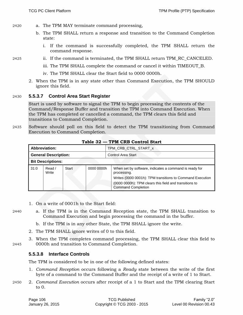
TCG PC Client Platform TPM Profile (PTP) Specification
Page 106 TCG Published Family “2.0” January 26, 2015 Copyright © TCG 2003 - 2015 Level 00 Revision 00.43
a. The TPM MAY terminate command processing, 2420
b. The TPM SHALL return a response and transition to the Command Completion state:
i. If the command is successfully completed, the TPM SHALL return the command response.
ii. If the command is terminated, the TPM SHALL return TPM_RC_CANCELED. 2425
iii. The TPM SHALL complete the command or cancel it within TIMEOUT_B.
iv. The TPM SHALL clear the Start field to 0000 0000h.
2. When the TPM is in any state other than Command Execution, the TPM SHOULD ignore this field.
5.5.3.7 Control Area Start Register 2430
Start is used by software to signal the TPM to begin processing the contents of the Command/Response Buffer and transition the TPM into Command Execution. When the TPM has completed or cancelled a command, the TPM clears this field and transitions to Command Completion.
Software should poll on this field to detect the TPM transitioning from Command 2435
Execution to Command Completion.
Table 32 — TPM CRB Control Start
Abbreviation: TPM_CRB_CTRL_START_x
General Description: Control Area Start
Bit Descriptions:
31:0 Read / Write
Start 0000 0000h When set by software, indicates a command is ready for processing.
Writes (0000 0001h): TPM transitions to Command Execution
(0000 0000h): TPM clears this field and transitions to Command Completion
1. On a write of 0001h to the Start field:
a. If the TPM is in the Command Reception state, the TPM SHALL transition to 2440
Command Execution and begin processing the command in the buffer.
b. If the TPM is in any other State, the TPM SHALL ignore the write.
2. The TPM SHALL ignore writes of 0 to this field.
3. When the TPM completes command processing, the TPM SHALL clear this field to 0000h and transition to Command Completion. 2445
5.5.3.8 Interface Controls
The TPM is considered to be in one of the following defined states:
1. Command Reception occurs following a Ready state between the write of the first byte of a command to the Command Buffer and the receipt of a write of 1 to Start.
2. Command Execution occurs after receipt of a 1 to Start and the TPM clearing Start 2450
to 0.

TCG PC Client Platform TPM Profile (PTP) Specification
Family “2.0” TCG Published Page 107 Level 00 Revision 00.43 Copyright © TCG 2003 - 2015 January 26, 2015
3. Command Completion occurs after completion of a command (indicated by the TPM clearing TPM_CRB_CTRL_Start_x to 0) and before a write of a 1 by the software to Request.goIdle.
4. Idle is any time TPM_CRB_CTRL_STS_x.Status.goIdle is 1. This will occur when 2455
the TPM is in Command Completion on receipt of a write of 1 by the software to TPM_CRB_CTRL_REQ_x.goIdle and is signaled by the TPM setting Status.tpmIdle to 1. This will also occur following locality change. Idle is the initial state of TPM upon completion of _TPM_INIT.
5. Ready is any time the TPM is ready to receive a command, following a write of 1 by 2460
software to Request.cmdReady, as indicated by the Status field being cleared to 0.
The following informative diagram is derived from the above normative statements. It is informative and only for illustrating diagrammatically the above TPM states and their transitions. The numbers in parentheses reference the states represented by row numbers in Table 33 — CRB Interface State Transitions. 2465
Figure 4 — TPM State Diagram for CRB Interface

TCG PC Client Platform TPM Profile (PTP) Specification
Page 108 TCG Published Family “2.0” January 26, 2015 Copyright © TCG 2003 - 2015 Level 00 Revision 00.43
5.5.3.9 TPM CRB Buffer
5.5.3.9.1 Access Restrictions
The command/response buffer may be implemented as a single buffer or as individual 2470
buffers. The data buffer is specified as having a minimum size large enough to handle the largest implemented TPM command or response with the maximum number of authorization handles and a hash algorithm of SHA-256.
The command/response buffer can only be accessed initially at the base address. Subsequent accesses are required to go to sequential addresses. In the case where 2475
software wants to reread a previous location, it must start at the base address.
5.5.3.9.2 TPM_CRB_DATA_BUFFER_x Access Restrictions
1. On a write to the buffer:
a. If the initial transaction is to an address other than the base address for the buffer, the TPM SHALL ignore the write. 2480
b. If subsequent transactions are to non-sequential addresses, the TPM MAY ignore the write.
c. If the transaction is a size other than 1 or power of 2 bytes, the TPM MAY ignore the write.
d. The TPM SHALL invalidate any existing data within the buffer upon a write to 2485
the base address of the buffer.
e. The TPM SHALL replace invalidated data with data written upon a write to the base address of the buffer.
f. Following the write to the buffer and prior to a write to TPM_CRB_CTRL_START_x, the TPM SHALL ignore read requests. 2490
2. On a read from the buffer:
a. If the initial transaction is to an address other than the base address for the buffer, the TPM SHALL ABORT the transaction, as defined in Section 5.5.1.1 Bus Aborts.
b. If subsequent transactions are to non-sequential addresses, the TPM MAY abort 2495
the transaction, as defined in Section 5.5.1.1 Bus Aborts.
c. Following the first transaction, if a subsequent read to the base address occurs, the TPM SHALL return the data at the base address.
d. On a write to the buffer, the TPM MAY ignore the data.
e. The TPM SHALL maintain the response in the buffer until receipt of a write of 1 2500
to TPM_CRB_CTRL_REQ_x.goIdle.
5.5.3.10 CRB Interface State Transitions
Table 33 shows the changes in CRB Interface fields based on the command or action done to the TPM. Notice this is not a state transition table covering the states defined in 5.5.3.8 Interface Controls rather a table describing how the status fields change 2505
based on initial condition and action taken. The following rules apply to Table 33.

TCG PC Client Platform TPM Profile (PTP) Specification
Family “2.0” TCG Published Page 109 Level 00 Revision 00.43 Copyright © TCG 2003 - 2015 January 26, 2015
1. There MAY be intermediate status field states, where a command has finished, but TPM_START field is not yet cleared. Software is expected to poll until the appropriate status field is set.
2. This table applies only to CRB Interface field states where a locality has already 2510
been selected and no change in locality is performed.
3. The statements in the column labeled “Action Taken” are informative when shaded and are derived from normative statements contained within the definitions of the CRB Interface in Section 5.5.3 CRB Interface Requirements. If there is an inconsistency between this column and the statements within normative 2515
definitions of the CRB Interface fields take precedence.
4. Normal transitions are highlighted in yellow and are indexed to the state transitions illustrated in Figure 4.
5. The following abbreviations are used in Table 33:
Label Bit Definition
C/R TPM_REQ.cmdReady
gI TPM_REQ.goIdle
I TPM_STS_tpmIdle
St TPM_STS_tpmSts
S TPM_START
CC TPM_COMMAND_CANCEL
— No TPM access for the corresponding data element
X
Either 0 or 1. The TPM is allowed to maintain this field as either value for this state. Software SHALL be capable of managing the TPM if either case is implemented.

TCG PC Client Platform TPM Profile (PTP) Specification
Family “2.0” TCG Published Page 110 Level 00 Revision 00.43 Copyright © TCG 2003 - 2015 January 26, 2015
Table 33 — CRB Interface State Transitions 2520
# Present State of Control Area Fields/Data Written Next State & Result Action Taken
State Request Status S CC Request S CC State (Row)
Request Status S CC Description
C/R gI I St C/R gI Command Response Buffer
C/R gI I St
0 Init - - - - - - X X - X X Idle (1) 0 0 1 0 0 0 TPM Transitions from Init to Idle within TIMEOUT_B
1 Idle 0 0 1 0 0 0 1 0 - X X Ready 0 0 0 0 0 0 TPM Transitions to Ready within TIMEOUT_C
2 Idle 0 0 1 0 0 0 0 1 - X X Idle 0 0 1 0 0 0 TPM remains in Idle. TPM MAY ignore request.
3 Idle 0 0 1 0 0 0 X X - 1 0 Idle 0 0 1 0 0 0 TPM remains in Idle. TPM ignores request
4 Idle 0 0 1 0 0 0 X X - 0 1 Idle 0 0 1 0 0 0 No command to Cancel. TPM remains in Idle. TPM SHOULD ignore Cancel field.
5 Idle 0 0 1 0 0 0 X X Write access to buffer 0 0 Idle 0 0 1 0 0 0 TPM SHALL ignore any access to the C/R buffer
6 Idle 0 0 1 0 0 0 X X Read access to buffer 0 0 Idle 0 0 1 0 0 0 TPM SHALL ignore any access to the C/R buffer
7 Ready 0 0 0 0 0 0 1 0 - 0 0 Ready 0 0 0 0 0 0 TPM remains in Ready. TPM SHALL ignore request
8 Ready 0 0 0 0 0 0 0 1 - 0 0 Idle 0 0 1 0 0 0 Interface Reset. TPM goes to Idle state.
9 Ready 0 0 0 0 0 0 X X Write access to the buffer 0 0 Reception 0 0 0 0 0 0 TPM receives command
10 Ready 0 0 0 0 0 0 0 0 - 1 0 Ready 0 0 0 0 0 0 No data in the buffer, TPM remains in Ready. TPM SHALL ignore request
11 Ready 0 0 0 0 0 0 0 0 - 0 1 Ready 0 0 0 0 0 0 No command to cancel. TPM remains in Ready. TPM SHALL Ignore request.
12 Ready 0 0 0 0 0 0 X X Read access to buffer 0 0 Ready 0 0 0 0 0 0 No response to read. TPM remains in Ready. TPM SHOULD ignore request.
13 Reception 0 0 0 0 0 0 0 0 - 1 0 Execution 0 0 0 0 1 0 TPM transitions to Execution state. TPM begins processing command.
14 Reception 0 0 0 0 0 0 0 0 - 0 1 Reception 0 0 0 0 0 0 TPM remains in Reception. TPM SHALL ignore request.
15 Reception 0 0 0 0 0 0 1 0 - 0 0 Ready 0 0 0 0 0 0 TPM transitions to Ready.
16 Reception 0 0 0 0 0 0 0 0 - 0 0 Reception 0 0 0 0 0 0 TPM remains in Reception.
17 Reception 0 0 0 0 0 0 0 0 Read access to buffer 0 0 Reception 0 0 0 0 0 0 TPM remains in Reception. TPM SHALL ignore request.
18 Reception 0 0 0 0 0 0 0 0 Write access to the buffer 0 0 Reception 0 0 0 0 0 0 TPM in Reception. TPM continues to receive data.

TCG PC Client Platform TPM Profile (PTP) Specification
Family “2.0” TCG Published Page 111 Level 00 Revision 00.43 Copyright © TCG 2003 - 2015 January 26, 2015
# Present State of Control Area Fields/Data Written Next State & Result Action Taken
State Request Status S CC Request S CC State (Row)
Request Status S CC Description
C/R gI I St C/R gI Command Response Buffer
C/R gI I St
19 Reception 0 0 0 0 0 0 0 1 - 0 0 Idle 0 0 1 0 0 0 Abort Command Reception and return to Idle.
20 Execution 0 0 0 0 1 0 0 0 - 1 0 Execution 0 0 0 0 1 0 TPM remains in Execution state. TPM MAY ignore writes to Start field.
21 Execution 0 0 0 0 1 0 1 0 - X 0 Execution 0 0 0 0 1 0 TPM remains in Execution state. TPM SHALL ignore request.
22 Execution 0 0 0 0 1 0 0 1 - X 0 Execution 0 0 0 0 1 0 TPM remains in Execution state. TPM SHALL ignore request.
23 Execution 0 0 0 0 1 0 0 0 - X 0 Completion 0 0 0 0 0 0 TPM clears Start field and transitions to Completion.
24 Execution 0 0 0 0 1 1 0 0 X 1 Completion 0 0 0 0 0 0 The TPM shall transition to Completion. TPM MAY Cancel command. TPM SHALL respond with Return code within TIMEOUT_B.
25 Execution 0 0 0 0 1 0 0 0 Write access to buffer X 0 Execution 0 0 0 0 1 0 TPM remains in Execution state. TPM MAY ignore write requests
26 Execution 0 0 0 0 1 0 0 0 Read access to buffer X 0 Execution 0 0 0 0 1 0 TPM remains in Execution state. TPM MAY ignore read requests
27 Completion 0 0 0 0 0 0 1 0 - 0 0 Completion 0 0 0 0 0 0 TPM remains in Completion. TPM SHALL ignore request.
28 Completion 0 0 0 0 0 0 0 1 - 0 0 Idle 0 0 1 0 0 0 TPM transitions to Idle, invalidates buffer.
29 Completion 0 0 0 0 0 0 0 0 - 1 0 Completion 0 0 0 0 0 0 TPM remains in Completion. TPM SHALL ignore request
30 Completion 0 0 0 0 0 0 0 0 - 0 1 Completion 0 0 0 0 0 0 TPM remains in Completion. TPM SHALL ignore request
31 Completion 0 0 0 0 0 0 0 0 Read access to buffer, sequential accesses
0 0 Completion 0 0 0 0 0 0 TPM returns data, remains in Completion and maintains data in buffer.
32 Completion 0 0 0 0 0 0 0 0 Read access to buffer, non-sequential accesses
0 0 Completion 0 0 0 0 0 0 Invalid access. TPM MAY ignore the transaction.
33 Completion 0 0 0 0 0 0 0 0 Read access, re-read from Base address
0 0 Completion 0 0 0 0 0 0 Retry. TPM resets internal byte counter and returns response from Base address.

TCG PC Client Platform TPM Profile (PTP) Specification
Family “2.0” TCG Published Page 112 Level 00 Revision 00.43 Copyright © TCG 2003 - 2015 January 26, 2015
5.6 Interrupts
As use of the TPM is non-preemptive (except for the special case of Seize) and the TPM is single threaded, there is no issue with regard to sharing or colliding interrupts across localities. For example, if one locality starts a TPM operation, it cannot release the TPM to another locality until the pending TPM operation completes. However, if 2525
one locality (e.g., Locality 0) starts a long TPM operation, then turns control to another locality (e.g., Locality 2) before the long operation completes (and of course does not relinquish the TPM, which would cause a command abort), the second locality (e.g., Locality 2) would not know what the interrupt is for. This situation is outside the purview of this specification and negotiation of interrupt handling is done by the 2530
software.
When an event occurs that causes the TPM to signal an interrupt, the TPM must set the appropriate fields in the TPM_INT_STATUS_x or TPM_CRB_INT_STS_x register. If the TPM has not already sent an interrupt, the 0 to 1 transition of a field in the
TPM_INT_STATUS_x or the TPM_CRB_INT_STS_x register must cause the TPM to 2535
assert the appropriate interrupt per the SIRQ or PIRQ protocol. The interrupt service routine will read the TPM_INT_STATUS_x or TPM_CRB_INT_STS_x register to determine the cause and take appropriate action. When the interrupt has been serviced, the interrupt service routine must do an End-of-Interrupt (EOI) to the I/O APIC to re-arm the TPM’s interrupt in the I/O APIC. Then the interrupt service routine 2540
must also send a TPM_EOI to the TPM to allow it to send new interrupts.
The TPM must not issue another interrupt until it has received its TPM_EOI message (see below), even if new events occur that should cause an interrupt. The TPM should set the appropriate field in TPM_INT_STATUS_x or TPM CRB_INT_STS_x register, but the actual assertion of the interrupt will only occur after the TPM_EOI. If the interrupt 2545
handler detects multiple fields set, it may handle all the causes and clear multiple status fields. This means that an interrupt may be handled without actually causing a new interrupt.
The TPM_EOI to the TPM is writing a 1 to the field in the TPM_INT_STATUS_x or TPM_CRB_INT_STS_x register that corresponds to the type of interrupt just handled. 2550
Software may write multiple fields if it has handled multiple interrupt causes at one time.
The following informative sections are added for clarification. They should not change functionality.
If there are multiple fields set in the Interrupt register, and software does not clear all 2555
the interrupts, then the TPM must issue another interrupt after it sees the TPM_EOI, which is a write to the Interrupt register.
The software must not change the state of the TPM_INT_ENABLE_x globalIntEnable or TPM_CRB_INT_ENABLE_x.globalIntEnable flag while an interrupt is active.
For example: if after the write to the Interrupt register, there are fields still set, the 2560
TPM issues another interrupt. If software writes all the fields of the Interrupt register, so that after the write the register = 0, no new interrupt would be generated.
This covers the case that software handles one interrupt at a time and then returns. It also covers the case that software handles all the interrupts it knows about, so writes multiple fields into the Interrupt register, but a new interrupt is flagged between the 2565
time software read the Interrupt register and the time it wrote the TPM_EOI.
Application Note:
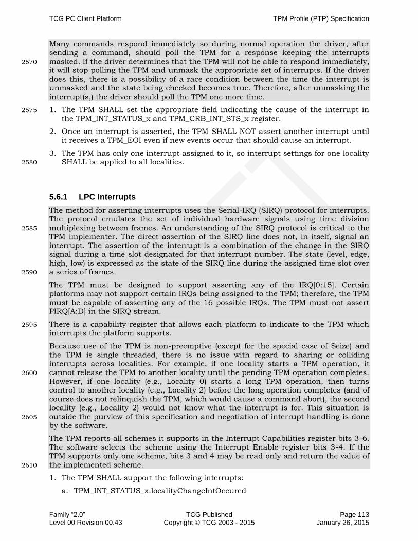
TCG PC Client Platform TPM Profile (PTP) Specification
Family “2.0” TCG Published Page 113 Level 00 Revision 00.43 Copyright © TCG 2003 - 2015 January 26, 2015
Many commands respond immediately so during normal operation the driver, after sending a command, should poll the TPM for a response keeping the interrupts masked. If the driver determines that the TPM will not be able to respond immediately, 2570
it will stop polling the TPM and unmask the appropriate set of interrupts. If the driver does this, there is a possibility of a race condition between the time the interrupt is unmasked and the state being checked becomes true. Therefore, after unmasking the interrupt(s,) the driver should poll the TPM one more time.
1. The TPM SHALL set the appropriate field indicating the cause of the interrupt in 2575
the TPM_INT_STATUS_x and TPM_CRB_INT_STS_x register.
2. Once an interrupt is asserted, the TPM SHALL NOT assert another interrupt until it receives a TPM_EOI even if new events occur that should cause an interrupt.
3. The TPM has only one interrupt assigned to it, so interrupt settings for one locality SHALL be applied to all localities. 2580
5.6.1 LPC Interrupts
The method for asserting interrupts uses the Serial-IRQ (SIRQ) protocol for interrupts. The protocol emulates the set of individual hardware signals using time division multiplexing between frames. An understanding of the SIRQ protocol is critical to the 2585
TPM implementer. The direct assertion of the SIRQ line does not, in itself, signal an interrupt. The assertion of the interrupt is a combination of the change in the SIRQ signal during a time slot designated for that interrupt number. The state (level, edge, high, low) is expressed as the state of the SIRQ line during the assigned time slot over a series of frames. 2590
The TPM must be designed to support asserting any of the IRQ[0:15]. Certain platforms may not support certain IRQs being assigned to the TPM; therefore, the TPM must be capable of asserting any of the 16 possible IRQs. The TPM must not assert PIRQ[A:D] in the SIRQ stream.
There is a capability register that allows each platform to indicate to the TPM which 2595
interrupts the platform supports.
Because use of the TPM is non-preemptive (except for the special case of Seize) and the TPM is single threaded, there is no issue with regard to sharing or colliding interrupts across localities. For example, if one locality starts a TPM operation, it cannot release the TPM to another locality until the pending TPM operation completes. 2600
However, if one locality (e.g., Locality 0) starts a long TPM operation, then turns control to another locality (e.g., Locality 2) before the long operation completes (and of course does not relinquish the TPM, which would cause a command abort), the second locality (e.g., Locality 2) would not know what the interrupt is for. This situation is
outside the purview of this specification and negotiation of interrupt handling is done 2605
by the software.
The TPM reports all schemes it supports in the Interrupt Capabilities register bits 3-6. The software selects the scheme using the Interrupt Enable register bits 3-4. If the TPM supports only one scheme, bits 3 and 4 may be read only and return the value of the implemented scheme. 2610
1. The TPM SHALL support the following interrupts:
a. TPM_INT_STATUS_x.localityChangeIntOccured

TPM Profile (PTP) Specification TCG PC Client Platform
Page 114 TCG Published Family “2.0” January 26, 2015 Copyright © TCG 2003 - 2015 Level 00 Revision 00.43
b. TPM_INT_STATUS_x.dataAvailIntOccured
2. The TPM MAY support the following interrupts:
a. TPM_INT_STATUS_x.stsValidIntOccurred 2615
b. TPM_INT_STATUS_x.commandReadyIntOccured
3. The TPM SHALL support asserting any of the IRQ[0:15]. The TPM SHALL NOT assert PIRQ[A:D] in the SIRQ stream.
4. The TPM SHALL support low level interrupts, defined in Table 34, and MAY support the other interrupts. The TPM SHALL report all schemes it supports in the 2620
Interface Capabilities register.
5. If the TPM supports only one scheme, bits 3 and 4 MAY be read-only and return the value of the implemented scheme.
6. The TPM SHALL maintain interrupts as inactive during any change to the TPM_INT_ENABLE_x globalIntEnable and while TPM_INT_ENABLE_x 2625
globalIntEnable is 0.

TCG PC Client Platform TPM Profile (PTP) Specification
Family “2.0” TCG Published Page 115 Level 00 Revision 00.43 Copyright © TCG 2003 - 2015 January 26, 2015
5.6.1.1 LPC Interrupt Enable
Table 34 — LPC Interrupt Enable
Abbreviation: TPM_INT_ENABLE_x
General Description: Enables specific interrupts and has the global enable. The TPM SHALL implement this register.
Bit Descriptions:
31 Read/ Write
globalIntEnable Default:0 1 = Interrupts controlled by individual bits
0= All interrupts disabled.
cleared to 0 on reset.
30:8 Reserved Reads always return 0
7 Read/ Write
commandReadyEnable Default: 0 1 = Enabled
0 = Disabled
6:5 reserved Reads always return 0
Note to readers and future editors: This displacement of the enable fields (i.e. TPM_INT_ENABLE_x.commandReadyEnable not being adjacent to the other enable fields) here and in the tables below was done because the TPM_INT_ENABLE_x.commandReadyEnable field was added late in the draft cycle of this release (1.2). Some TPM manufacturers could not change their implementation in a timely manner if we moved the TPM_INT_ENABLE_x.typePolarity fields.
4:3 Read/ Write
typePolarity Default: 01 00 = High level
01 = Low level
10 = Rising edge
11 = Falling edge
2 Read/ Write
localityChangeIntEnable Default: 0 1 = Enabled
0 = Disabled
1 Read/ Write
stsValidIntEnable Default: 0 1 = Enabled
0 = Disabled
0 Read/ Write
dataAvailIntEnable Default: 0 1 = Enabled
0 = Disabled

TPM Profile (PTP) Specification TCG PC Client Platform
Page 116 TCG Published Family “2.0” January 26, 2015 Copyright © TCG 2003 - 2015 Level 00 Revision 00.43
5.6.1.2 Interrupt Status
Table 35 — Interrupt Status 2630
Abbreviation: TPM_INT_STATUS_x
General Description: Shows which interrupt has occurred. The TPM SHALL implement this register.
Bit Descriptions:
31:8 Reserved Default : 0 Reads always return 0
7 Read /
Write 1
commandReadyIntOccured Default: 0 When 1, indicates the TPM_STS_x.commandReady field transitioned from 0 to 1.
Writing a 1 to this field clears the interrupt.
Writing a 0 to this field has no effect.
6:3 reserved Default: 0 Reads always return 0
2 Read /
Write 1
localityChangeIntOccured Default: 0 When 1, indicates the locality change interrupt occurred. This interrupt is caused whenever any locality moves from TPM_ACCESS_x.requestUse to TPM_ACCESS_x.activeLocality whenever this transition had been delayed due to another locality having TPM_ACCESS_x.activeLocality set.
Note that if the TPM has no TPM_ACCESS_x.activeLocality set when TPM_ACCESS_x.requestUse is written, the TPM SHALL move directly from TPM_ACCESS_x.requestUse to TPM_ACCESS_x.activeLocality without causing the interrupt.
Writing a 1 to this field clears the interrupt (i.e., a TPM_EOI).
Writing a 0 to this field has no effect.
1 Read /
Write 1
stsValidIntOccurred Default: 0 This interrupt indicates a 0 to 1 transition on TPM_STS_x.stsValid.
Writing a 1 to this field clears the interrupt.
Writing a 0 to this field has no effect.
0 Read /
Write 1
dataAvailIntOccured Default: 0 This interrupt indicates that TPM_STS_x.dataAvail transitioned from a 0 to a 1. This 0 to 1 transition occurs when the command has been completed and there is a Response to be read. This transition SHALL only occur when both TPM_STS_x.dataAvail and TPM_STS_x.stsValid fields are 1.
Writing a 1 to this field clears the interrupt.
Writing a 0 to this field has no effect.

TCG PC Client Platform TPM Profile (PTP) Specification
Family “2.0” TCG Published Page 117 Level 00 Revision 00.43 Copyright © TCG 2003 - 2015 January 26, 2015
5.6.1.3 Interrupt Vector
Table 36 — Interrupt Vector
Abbreviation: TPM_INT_VECTOR_x
General Description: Contains the SIRQ value. The TPM SHALL implement this register.
Bit Descriptions:
7:4 Read Only Reserved (0) Default: 0 Read always return 0’s; writes have no meaning.
3:0 Read / Write sirqVec Default: 0 A value of 0 means SIRQ is disabled and SIRQ is tristated. The SIRQ channel used by TPM can be from 1 to 15.
5.6.2 CRB Interrupts
During all interactions of the Software with the TPM there are several situations where 2635
Software has to wait for the TPM completing a requested action. Completion of a requested action will be indicated from the TPM to Software by a change of the corresponding status register change.
Actually there are 4 state transitions which may provide a benefit for the overall system performance when being indicated to the Software via an interrupt instead of 2640
polling:
Locality Change: Write 1 to TPM_LOC_CTRL_x.requestAccess => Wait for Locality x to be SET
Establishment Clear: Write to TPM_LOC_CTRL_x.resetEstablishmentBit => Wait for TPM_ESTABLISHMENT == 1 2645
TPM Ready: Write 1 to TPM_CRB_CTRL_REQ_x.cmdReady => Wait for tpmIdle == 0
Response Available: Write 1 to TPM_CRB_CTRL_x.Start => Wait for Start == 0
To allow for a flexible configuration and use of the interrupt it is necessary to provide the following fields: 2650
Interrupt Enable: Allows configuration of the TPM which interrupt source should be used
Interrupt Status: Allows reading the source of an Interrupt asserted by the TPM
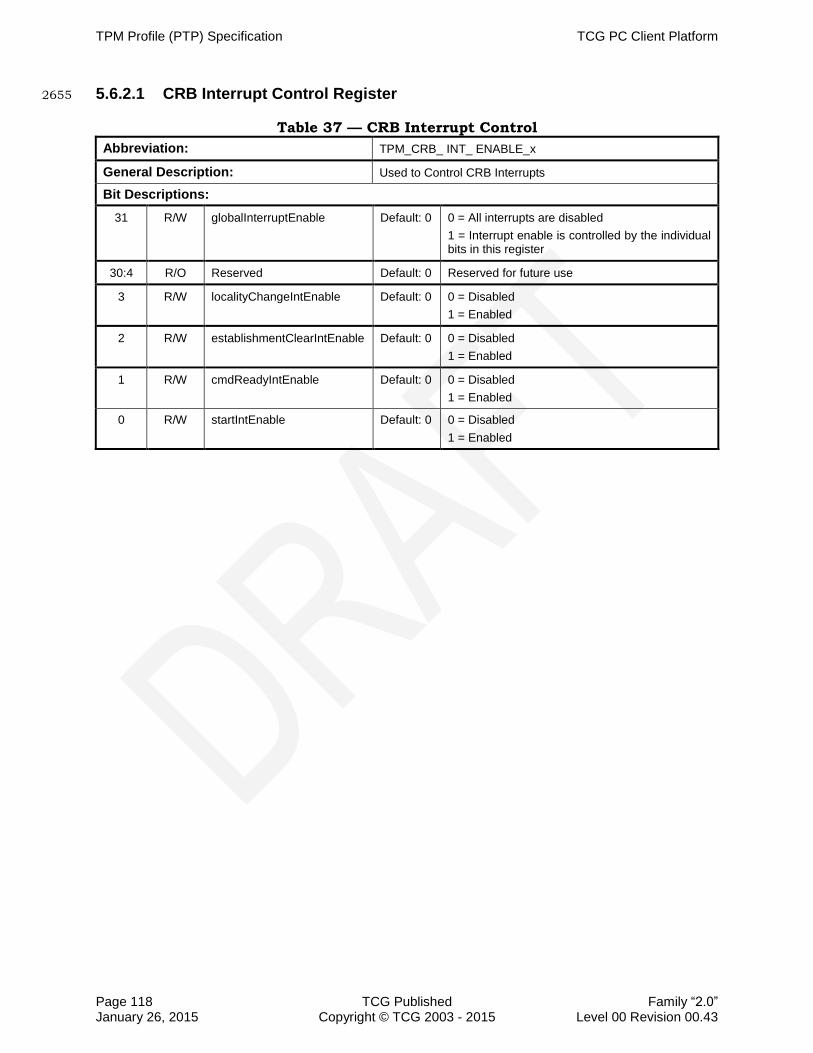
TPM Profile (PTP) Specification TCG PC Client Platform
Page 118 TCG Published Family “2.0” January 26, 2015 Copyright © TCG 2003 - 2015 Level 00 Revision 00.43
5.6.2.1 CRB Interrupt Control Register 2655
Table 37 — CRB Interrupt Control
Abbreviation: TPM_CRB_ INT_ ENABLE_x
General Description: Used to Control CRB Interrupts
Bit Descriptions:
31 R/W globalInterruptEnable Default: 0 0 = All interrupts are disabled
1 = Interrupt enable is controlled by the individual bits in this register
30:4 R/O Reserved Default: 0 Reserved for future use
3 R/W localityChangeIntEnable Default: 0 0 = Disabled
1 = Enabled
2 R/W establishmentClearIntEnable Default: 0 0 = Disabled
1 = Enabled
1 R/W cmdReadyIntEnable Default: 0 0 = Disabled
1 = Enabled
0 R/W startIntEnable Default: 0 0 = Disabled
1 = Enabled

TCG PC Client Platform TPM Profile (PTP) Specification
Family “2.0” TCG Published Page 119 Level 00 Revision 00.43 Copyright © TCG 2003 - 2015 January 26, 2015
Table 38 — Interrupt Status
Abbreviation: TPM_CRB_ INT_STS_x
General Description: Shows which interrupt has occurred.
Bit Descriptions:
31:4 R/O Reserved Default: 0 Reserved for future use
3 Read/ Write 1
localityChangeInt Default: 0 A 1 indicates that a locality change has occurred. This interrupt is caused whenever the value of bits 4:2 of the TPM_LOC_STATE register changes
Note: If the TPM has
TPM_LOC_STATE_x.locAssigned == 0 before Request Use is set there will be no Interrupt because the TPM will make the transition immediately to the requesting locality
Writing a 1 to this field clears the interrupt.
Writing a 0 to this field has no effect.
2 Read/ Write 1
establishmentClearInt Default: 0 A 1 indicates that the reset of the TPM_LOC_STATE_x.tpmEstablished field has been successfully executed after the corresponding request TPM_LOC_CTRL_x.resetEstablishment
Writing a 1 to this field clears the interrupt.
Writing a 0 to this field has no effect.
1 Read/ Write 1
cmdReadyInt Default: 0 A 1 indicates that after a write of 1 to TPM_CTRL_REQ.cmdReady the TPM has successfully finished the transition to the Ready state (i.e. TPM_CRB_CTRL_STS_x.tpmIdle == 0)
Writing a 1 to this field clears the interrupt.
Writing a 0 to this field has no effect.
0 Read/ Write 1
startInt Default: 0 A 1 indicates that the TPM has executed a command as requested by TPM_CTRL_Start_x = 0001 and the corresponding response is available for read-out (i.e. Start field has been cleared). This interrupt will also be triggered if the currently executed command will be cancelled via a Command Cancel.
Writing a 1 to this field clears the interrupt.
Writing a 0 to this field has no effect.

TPM Profile (PTP) Specification TCG PC Client Platform
Page 120 TCG Published Family “2.0” January 26, 2015 Copyright © TCG 2003 - 2015 Level 00 Revision 00.43
6 TPM Hardware 2660
6.1 FIFO Interface Locality Usage per Register
Table 39 shows how the TPM responds to access to each of the interface registers based on locality settings for the FIFO interface.
1. If TPM_ACCESS_x.activeLocality setting changes when a command is executing, the TPM SHALL abort the currently executing command, as defined in Section 2665
5.5.2.3.1 Command Aborts.
Table 39 — Register Behavior Based on Locality Setting for FIFO
TPM_ACCESS_x.activeLocality
Set for This Locality Set for other Locality Not Set
READ WRITE READ WRITE READ WRITE
TPM_STS_x Registers
TPM returns correct value
Fields updated TPM returns FFh TPM Ignore the write
TPM returns FFh TPM Ignore the write
TPM_INT_ENABLE_x Registers
TPM returns correct value
Field updated TPM returns correct value
TPM Ignore the write
TPM returns correct value
TPM Ignore the write
TPM_INT_VECTOR_x Registers
TPM returns correct value
Field updated TPM returns correct value
TPM Ignore the write
TPM returns correct value
TPM Ignore the write
TPM_INT_STATUS_x Registers
TPM returns correct value
Interrupt cleared TPM returns correct value
TPM Ignore the write
TPM returns correct value
TPM Ignore the write
TPM_INTF_CAPABILITY_x Registers
TPM returns correct value
Read-only register
TPM returns correct value
Read-only register
TPM returns correct value
Read-only register
TPM_ACCESS_x Registers
TPM returns correct value
Fields updated TPM returns correct value
Fields updated TPM returns correct value
Fields updated
TPM_DATA_FIFO_x Registers
TPM returns correct data
TPM accepts data and command
TPM returns FFh TPM Ignore the write
TPM returns FFh TPM Ignore the write
Configuration registers – 0F00h to 0FFFh
TPM returns correct value
Fields updated TPM returns correct value
TPM Ignore the write
TPM returns correct value
TPM Ignore the write

TCG PC Client Platform TPM Profile (PTP) Specification
Family “2.0” TCG Published Page 121 Level 00 Revision 00.43 Copyright © TCG 2003 - 2015 January 26, 2015
TPM_ACCESS_x.activeLocality
Set for This Locality Set for other Locality Not Set
READ WRITE READ WRITE READ WRITE
TPM_HASH_START Register
TPM returns FFh TPM accepts command
TPM returns FFh TPM Ignore the write
TPM returns FFh
TPM accepts (and sets TPM_ACCESS_x.activeLocality for Locality 4)
TPM_HASH_DATA Register
TPM returns FFh TPM accepts data
TPM returns FFh TPM Ignore the write
TPM returns FFh TPM Ignore the write
TPM_HASH_END Register
TPM returns FFh
TPM accepts command and clears TPM_ACCESS_x.activeLocality for Locality 4
TPM returns FFh TPM Ignore the write
TPM returns FFh TPM Ignore the write

TPM Profile (PTP) Specification TCG PC Client Platform
Page 122 TCG Published Family “2.0” January 26, 2015 Copyright © TCG 2003 - 2015 Level 00 Revision 00.43
6.2 CRB Interface Locality Usage Per Register
Table 40 shows how the TPM responds to access to each of the interface registers based on locality settings for the CRB interface. 2670
1. If TPM_LOC_STATE_x.activeLocality setting changes when a command is executing, the TPM SHALL abort the currently executing command, as defined in Section 5.5.1.1 Bus Aborts.
Table 40 — Register Behavior Based on Locality Setting for CRB
TPM_ACCESS_x.activeLocality
Set for This Locality Set for other Locality Not Set
READ WRITE READ WRITE READ WRITE
TPM_LOC_STATE_x Registers
TPM returns correct value
Read-only register
TPM returns correct value
Read-only register
TPM returns correct value
Read-only register
TPM_LOC_CTRL_x Registers
TPM returns 0 Field updated TPM returns 0 Field updated TPM returns 0 Field updated
TPM_LOC_STS_x Registers
TPM returns correct value
Read-only register
TPM returns correct value
Read-only register
TPM returns correct value
Read-only register
TPM_CRB_INTF_ID_x Registers
TPM returns correct value
Field updated TPM returns correct value
Field updated TPM returns correct value
Field updated
TPM_CRB_CTRL_x Registers
TPM returns correct value
Fields updated TPM returns FFh TPM Ignore the write
TPM returns FFh TPM Ignore the write
TPM_CRB_DATA_BUFFER_x Registers
TPM returns response data
TPM accepts command or data
TPM returns FFh TPM Ignore the write
TPM returns FFh TPM Ignore the write
TPM_LOC_CTRL_4.HASH_START Field
TPM returns 0
TPM accepts (and sets TPM_LOC_STATE_x.activeLocality to Locality 4)
TPM returns 0 TPM Ignore the write
TPM returns 0
TPM accepts (and sets TPM_LOC_STATE_x.activeLocality to Locality 4)
TPM_LOC_CTRL_4.TPM_HASH_DATA Field
TPM returns 0 TPM consumes data in command buffer
TPM returns 0 TPM Ignore the write
TPM returns 0 TPM Ignore the write
TPM_LOC_CTRL_4.TPM_HASH_END Field
TPM returns 0 TPM finalize and extend data and release Locality
TPM returns 0 TPM Ignore the write
TPM returns 0 TPM Ignore the write
2675

TCG PC Client Platform TPM Profile (PTP) Specification
Family “2.0” TCG Published Page 123 Level 00 Revision 00.43 Copyright © TCG 2003 - 2015 January 26, 2015
6.3 TPM LPC Hardware Protocol
This specification addresses 2.0 compliant TPM’s which make use of the LPC bus for interconnecting to the platform, as there are specific protocol requirements for TPM’s using LPC. The definition of specific LPC requirements does not preclude the use of other interfaces on a 2.0 compliant TPM. Future versions of this specification may 2680
address other bus interfaces.
1. If a TPM implements an LPC interface as the method of connecting to the trusted process, it SHALL implement the LPC bus per the requirements of the LPC Interface Specification. A link may be found to the specification in Section 7 References. 2685
2. If a TPM implements an LPC interface, the TPM MAY use the LPC CLKRUN# protocol for mobile platforms.
3. If a TPM implements an LPC interface, the TPM SHALL be designed such that the LPCPD# pin may be strapped high to disable the LPCPD# protocol.
6.3.1 LPC Locality Cycles for TPM Interface 2690
This section only applies to TPM implementations using the LPC interface.
This specification defines two LPC locality cycles, TPM-Write and TPM-Read, which were added for communication between the chipset and the TPM. On the LPC bus, with the exception of the START field, these cycles are identical to I/O cycles. These locality cycles are an additional flag to the TPM (beyond addressing) that the cycles are 2695
intended for the TPM as locality commands. These commands can only be generated by a trusted process, e.g. the chipset.
See Section 5.2.1 TPM Locality Levels for rules and restrictions on using the standard vs. Locality LPC cycles.
By definition, the Locality None level is lower than Locality 0. 2700
1. If the TPM supports Locality None and Locality None is the active locality, any TPM access request from Locality 0-4 is a higher locality priority. In this case, the TPM SHALL respond to Locality 0-4 register writes to TPM_ACCESS_x.requestUse and TPM_ACCESS_x.Seize per the requirements documented in Section 5.5.2.4 Access Register. 2705
6.3.1.1 TPM-Write LPC Locality Cycle
Table 41 shows the TPM-Write locality cycle format. It is similar to the existing LPC I/O write.
If the CPU attempts to write more than 1 byte at a time to the TPM, the chipset must break this up into multiple cycles of 1 byte each to consecutive addresses. 2710

TPM Profile (PTP) Specification TCG PC Client Platform
Page 124 TCG Published Family “2.0” January 26, 2015 Copyright © TCG 2003 - 2015 Level 00 Revision 00.43
Table 41 — LPC Locality Cycle TPM-Write for Accessing the TPM
Field Value for Bits [3:0] Description
START 0101 Previously this was a reserved value. It is now allocated for TPM-Write and TPM-Read locality cycles.
CYCTYPE + DIR 0010 Same as used for standard LPC I/O Write
ADDR See Description Four nibbles. Same as the standard LPC I/O Write.
DATA-Low DIGEST low nibble
DATA-High DIGEST high nibble
TAR Standard LPC TAR
SYNC Standard SYNC field for an I/O Write
TAR Standard LPC TAR
6.3.1.2 TPM-Read LPC Locality Cycle
Table 42 shows the TPM-Read locality cycle format. It is similar to the existing LPC I/O read.
If the CPU attempts to read more than 1 byte at a time to the TPM, the chipset must 2715
break this up into a series of 1-byte reads to consecutive addresses.
Table 42 — LPC Cycle TPM-Read for Accessing the TPM
Field Value for Bits [3:0] Description
START 0101 Previously this was a reserved value. It is now allocated for TPM-Write and TPM-Read.
CYCTYPE + DIR 0000 Same as used for standard LPC I/O Read
ADDR See Description Same as for TPM-Write
TAR Standard LPC TAR
SYNC Standard Standard SYNC field for an I/O Read
DATA-Low DIGEST low nibble
DATA-High DIGEST high nibble
TAR Standard LPC TAR
6.4 SPI Hardware Protocol
There were a number of goals that guided architecture of SPI hardware protocol and flow control for the TPM. These assumptions are as follows: 2720
The TPM must have a dedicated SPI ChipSelect# (CS#).
Only the chipset is allowed to assert the TPM CS# signal. This means further that the TPM’s CS# can only be connected to the south bridge.
The SPI protocol should not break existing drivers or software.
The TPM Interface Specification 1.21 defines all registers as having a size of 4 bytes 2725
or less. This register size is maintained for compatibility with software. This applies to the _TPM_Hash_Start/_Data/_End functions, which may be generated by HW, because the TPM’s data register is only 4 bytes. No additional registers are defined for registers that might be greater than 4 bytes. Future definitions of SW may support 8-byte or 64-byte data registers. The SPI flow control and protocol 2730

TCG PC Client Platform TPM Profile (PTP) Specification
Family “2.0” TCG Published Page 125 Level 00 Revision 00.43 Copyright © TCG 2003 - 2015 January 26, 2015
are defined to allow for 8-byte and 64-byte data transactions in case they are added later. This allows for future improvements in SPI throughput. An example would be a 64-byte data register at offset 0x80. The 4-byte data register is always implemented and available to SW to maintain backwards compatibility.
In the future there may be uses where large amounts of data, for instance 4kB, need 2735
to be passed to the TPM.
6.4.1 Clocking
The LPC interface has a free-running clock, but the clock defined by the SPI interface only runs when an SPI transaction occurs. The TPM, to maintain backwards compatibility, is not required to have an external free-running clock. TPM 2740
manufacturers may choose to support an external clock in their implementations. The TPM must, however, generate whatever clock source it needs to support internal command processing, as this command processing will likely take place when the SPI bus is idle and the SPI clock is not running. Additionally, the TPM’s timer/tick counter is based on this internal clock and does not require external clock support. 2745
The SPI bus clock frequency may vary based on implementation and/or type of device attached. The TPM default clock frequency for PC Client platforms is defined to be 24MHz, but in future might be higher frequencies.
The SPI bus is a shared-bus architecture. As such, a PC OEM must take care to ensure compatibility between devices on a shared SPI bus. It is likely that there will 2750
be BIOS initiated accesses to an SPI ROM containing BIOS code on the same physical bus as an SPI TPM. The PC OEM has two options to deal with this case:
1. The platform and BIOS may be designed to start up at a frequency of 24MHz, as the TPM must support that clock frequency. The BIOS may increase the frequency for transactions to the BIOS ROM at a later point in POST. 2755
2. The platform may be designed with a strap or other hardware method to force operation at a particular frequency, as the PC OEM may select a TPM with support for that particular frequency.
Note 1: The SPI bus may be shared. Therefore when the TPM’s CS# is not asserted, the SPI clock may be running at a faster frequency than the TPM supports. Since 2760
BIOS knows what TPM is attached to which south bridge, it will need to comprehend the frequency support for both components and will change the SPI clock frequency for the TPM segment while SPI is idle. There is no communication to the TPM of what the SPI frequency is. The frequency can change from command to command, as long as the SPI bus is idle when the frequency changes. 2765
Note 2: TPM’s may be used in many types of PC Client platforms. In lower power environments, it is entirely likely that the SPI interface will run at a slower clock
frequency, while in high performance environments, the interface will run at a higher frequency. This specification provides a range within which all TPMs will correctly function and allows for TPM vendors to differentiate their parts to allow for a variety of 2770
implementations. PC Client systems have multiple standard clock frequencies available which could be used as the source clocks for the SPI interface, such as 14.3MHz, 24MHz, 33MHz, and 66MHz. To enable the widest range of applications, TPM vendors are encouraged to support frequencies between 33MHz and 66MHz in addition to the required clock operating range to allow for higher performance 2775
applications.
1. The TPM SHALL support an SPI clock frequency range of 10 - 24 MHz.

TPM Profile (PTP) Specification TCG PC Client Platform
Page 126 TCG Published Family “2.0” January 26, 2015 Copyright © TCG 2003 - 2015 Level 00 Revision 00.43
2. The TPM MAY support running at lower frequencies.
3. The TPM SHOULD support higher frequencies.
6.4.2 Electrical Specification 2780
The SPI interface does not have an industry standard for electrical characteristics that can be referenced for TPM implementations as was done for LPC. This section describes the normative requirements for the TPM as defined at the TPM pins. This does not describe the requirements for the south bridge.
1. The TPM SHALL support a supply and I/O voltage of 1.8V or 3.3V. 2785
2. The TPM MAY support supply and I/O voltages of both 1.8 and 3.3V.
3. The TPM MAY support other supply and I/O voltages.
4. The TPM SHALL comply with the electrical specifications in the tables below.
Note: For the electrical specifications in Table 45, the timing characteristics are defined only for the specified clock operating range. For other clock frequencies, the 2790
timing characteristics are implementation specific.
Table 43 — DC Specifications for 1.8V Supply Voltage
Parameter Conditions Min Max Units
Vcc power supply 1.65 1.95 V
VIH Vcc = 1.65V – 1.95V 0.7 * Vcc 0.3 + Vcc V
VIL Vcc = 1.65V – 1.95V -0.3 0.3 * Vcc V
VOH Vcc = 1.65V – 1.95V 0.9 * Vcc Iout = -100A
VOL Vcc = 1.65V – 1.95V 0.1 * Vcc 1.5 mA
Table 44 — DC Specifications for 3.3V Supply Voltage
Parameter Conditions Min Max Units
Vcc power supply 3.0 3.6 V
VIH Vcc= 3.0V – 3.6V 0.7*Vcc 0.5+VCC V
VIL Vcc= 3.0V – 3.6V -0.5V 0.3*VCC V
VOH Vcc = 3.0V – 3.60V 0.9 * Vcc Iout = -100A
VOL Vcc = 3.0V – 3.60V 0.1 * Vcc 1.5 mA

TCG PC Client Platform TPM Profile (PTP) Specification
Family “2.0” TCG Published Page 127 Level 00 Revision 00.43 Copyright © TCG 2003 - 2015 January 26, 2015
Table 45 — AC Electrical Specifications 2795
Parameter Description Conditions Min Max Units
Clock minimum operating range
10 24 MHz
tCLKf Clock Period Rising Edge to Rising Edge
1/fCLK-5% 1/fCLK+5% ns
tCLKr Nominal Clock Period
Nominal Clock Period 1/fCLK ns
tCLKL Clock Low Time Clock Low Time (see Figure 6)
0.45tCLKr - ns
tCLKH Clock High Time Clock High Time (see Figure 6)
0.45*tCLKr - ns
tCLKslew Clock Slew Rate 0.2*VCC – 0.6*VCC 1 4 V/ns
tCS CS# High Time Rising Edge to Falling Edge
50 ns
tCSS CS# Setup to clock CS Setup time 5 ns
tCSH CS# Hold to clock CS Hold time 5 ns
tSU MOSI Setup to clock Data Setup time 2 ns
tH MOSI Hold to clock Data Hold time 3 ns
tHO Clock to MISO valid Output Hold time 0 ns
tvmin Output valid from clock falling edge minimum
Output Valid Min 0 ns
tVmax Output valid from clock falling edge maximum
Output Valid Max 0.7* tCLKL ns
TPM SPI Pin Capacitance
10 pF
CS#
CLK
tCSS tCLKH tCLKL tCSH
tCS
tHO
VALID OUT
tV
HIGH IMPEDANCE HIGH IMPEDANCEMISO
MOSI VALID IN
tSU tH
Figure 5 — Timing Diagram
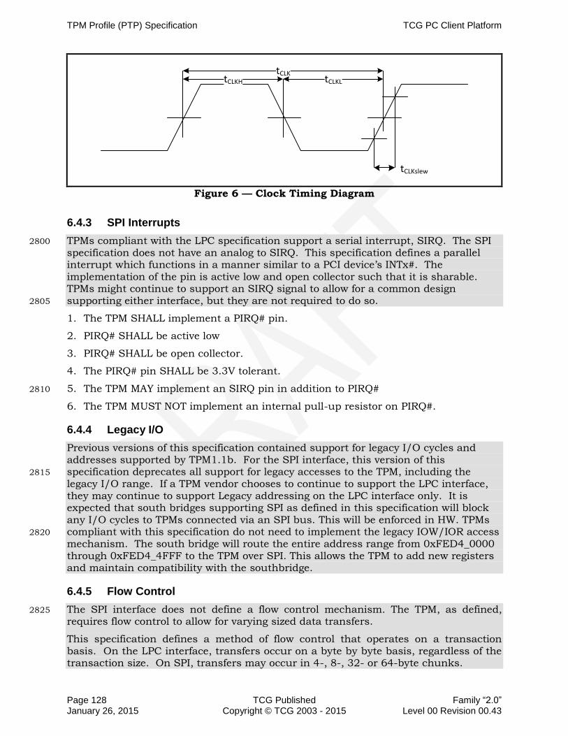
TPM Profile (PTP) Specification TCG PC Client Platform
Page 128 TCG Published Family “2.0” January 26, 2015 Copyright © TCG 2003 - 2015 Level 00 Revision 00.43
tCLKtCLKH tCLKL
tCLKslew
Figure 6 — Clock Timing Diagram
6.4.3 SPI Interrupts
TPMs compliant with the LPC specification support a serial interrupt, SIRQ. The SPI 2800
specification does not have an analog to SIRQ. This specification defines a parallel interrupt which functions in a manner similar to a PCI device’s INTx#. The implementation of the pin is active low and open collector such that it is sharable. TPMs might continue to support an SIRQ signal to allow for a common design supporting either interface, but they are not required to do so. 2805
1. The TPM SHALL implement a PIRQ# pin.
2. PIRQ# SHALL be active low
3. PIRQ# SHALL be open collector.
4. The PIRQ# pin SHALL be 3.3V tolerant.
5. The TPM MAY implement an SIRQ pin in addition to PIRQ# 2810
6. The TPM MUST NOT implement an internal pull-up resistor on PIRQ#.
6.4.4 Legacy I/O
Previous versions of this specification contained support for legacy I/O cycles and addresses supported by TPM1.1b. For the SPI interface, this version of this specification deprecates all support for legacy accesses to the TPM, including the 2815
legacy I/O range. If a TPM vendor chooses to continue to support the LPC interface, they may continue to support Legacy addressing on the LPC interface only. It is expected that south bridges supporting SPI as defined in this specification will block any I/O cycles to TPMs connected via an SPI bus. This will be enforced in HW. TPMs compliant with this specification do not need to implement the legacy IOW/IOR access 2820
mechanism. The south bridge will route the entire address range from 0xFED4_0000 through 0xFED4_4FFF to the TPM over SPI. This allows the TPM to add new registers and maintain compatibility with the southbridge.
6.4.5 Flow Control
The SPI interface does not define a flow control mechanism. The TPM, as defined, 2825
requires flow control to allow for varying sized data transfers.
This specification defines a method of flow control that operates on a transaction basis. On the LPC interface, transfers occur on a byte by byte basis, regardless of the transaction size. On SPI, transfers may occur in 4-, 8-, 32- or 64-byte chunks.

TCG PC Client Platform TPM Profile (PTP) Specification
Family “2.0” TCG Published Page 129 Level 00 Revision 00.43 Copyright © TCG 2003 - 2015 January 26, 2015
The method of flow control specified in this section allows the TPM to insert a wait 2830
state to hold off the transfer. Additionally, each transaction will provide, as part of the packet preceding the address, a transaction size. This allows a TPM vendor to implement more advanced mechanisms of flow control. For example, if the south bridge initiates a write of 32 bytes to the TPM_XData_FIFO or the TPM_CRB_DATA_BUFFER, the TPM can read the size of the transfer and, if it does not 2835
have 32 bytes of open space in its buffer, it would insert a wait state. Alternatively, the TPM could accept the transaction if it had a 64-byte buffer with only 8 bytes of data present. The TPM vendor isn’t required to verify transaction sizes before resorting to the flow control mechanism specified here. The TPM may choose to ignore the flow control method and choose to insert wait states, as defined here, if their 2840
buffer is not currently empty. This will have a performance impact on larger transaction sizes, but should pose no issue with 4-byte or 8-byte transfers. Byte level flow control was not considered, as the overhead of allowing flow control between each byte is too high with almost no benefit.
To allow flexibility for larger size transactions in the future, south bridges are likely to 2845
have limited, if any, HW checking on the size of accesses to the TPM address space. If the south bridge receives a transaction for any size from 1 byte to 64 bytes that doesn’t cross a 64-byte boundary, it may choose to accept and issue that transaction to the TPM on SPI as received. The TPM, if it doesn’t insert a wait state at the designated point must accept the transaction, as long as it doesn’t cross a register 2850
boundary. If the transaction crosses a register boundary, the TPM may choose to accept all of the data and discard the data that exceeds the size limit for that register as long as doing so does not cause a change to the state of any adjacent register. The flow control specified in this specification defines a transaction structure for SPI consisting of 1 byte of command (including direction of transfer and transaction size), 2855
3B of address, followed by the transaction data (either write data from the south bridge to the TPM or read data from the TPM to the south bridge). The TPM may insert wait states following receipt of the address. The south bridge will monitor the MISO line on the rising edge of the clock in the window following transmission of the last bit of the address. The TPM, in order to insert a wait state, drives the MISO line 2860
low (0) on the falling edge of the previous clock (clock in which the last bit of address is driven by the south bridge). The TPM would continue to drive MISO line in 8-bit increments until it is ready to receive or transmit data. The south bridge polls the MISO line every 8 clocks until it sees a 1, then it either starts to transmit data or expects to receive data on the next falling clock edge. 2865
Note: For the purposes of defining the flow control, on SPI the MOSI or MISO signal is driven by the owner on the clock’s falling edge, and captured by the receiver on the clock’s rising edge.
For a read, the command and address are driven on MOSI and the TPM responds with data on MISO. With no wait states, the TPM would drive data on the next falling clock 2870
edge following receipt of the last address bit on the rising edge of the clock. This is illustrated in Figure 7 below. The SB monitors the MISO pin in the same clock window that A[0] (the last address bit) is valid. If MISO is captured high on the rising edge of the clock, then the SB will continue to write or read data on the following clock edges. This aligns with standard SPI protocol where there are no wait states. In Figure 2875
7 — Example Read transaction with a WAIT state and Figure 8, if the TPM drives a 1 in the A[0] window, or in any subsequent wait state window, then MISO is no longer used for wait states, in which case MISO is either providing valid data for reads or is a don’t care for writes.

TPM Profile (PTP) Specification TCG PC Client Platform
Page 130 TCG Published Family “2.0” January 26, 2015 Copyright © TCG 2003 - 2015 Level 00 Revision 00.43
There is no further flow control allowed. Once the data starts coming from the TPM, it 2880
must provide the entire transaction’s worth of data, which can be from 1 to 64 bytes, depending on the TPM’s supported transaction size. In this example, if the SB had latched a 1 on the rising clock in the wait state window, then it would start latching in data starting on the next rising edge, which is the normal behavior without wait states. The TPM may insert any number of wait states that it needs. 2885
Since the wait state is defined as 0 on MISO, if there is no TPM present at all, then the design has a weak pull-up on MISO. If a TPM is not present, a pull-up on MISO means that the SB controller sees a 1, and will latch in 0xFF on the read. This follows standard master abort behavior of 0xFF for read data and matches the behavior when the TPM was on LPC. 2890
For writes, the mechanism is similar. If MISO is 0 to request a wait state, then the data driven during that byte is not valid and the TPM will drop the data. If there is a wait state, the master will drive the first byte of the transaction until the slave stops requesting wait states. The SB will sample MISO on the last data bit of the byte (multiples of 8 clocks after the first wait state window). Again, the TPM must hold 2895
MISO as 0 for 8 clocks each time it requests a wait state. If MISO is 1, this indicates the TPM is ready for the entire write, accepts the first byte which the SB has sent in the same clock, and the SB will then drive the 2nd and subsequent bytes on the following clocks. Once the data starts transmitting, the entire write data will be sent with no further flow control. See Figure 8 — Example of WRITE transaction with Wait 2900
state for an example of a write transaction with wait states inserted.
Wait states are byte based. For reads where MISO is used to return data to the master, the SB will start sampling at byte[-1], which is the window when A[7:0] is transmitted. If the last bit of this window is 0, then the TPM is requesting a wait state and the SB continues reading MISO for 8 clocks (a byte’s worth) and will look at the 2905
last bit to determine if there should be another wait state or not. From the SB standpoint, it is simply reading a byte and processing it as a byte. The last bit of that byte determines what to do next. If the bit is 1, then the SB knows to start sending the valid data on writes, or receiving data for reads. One option on writes is to send data byte 0 over and over until there is no wait state, and then move to byte 1, etc. For 2910
reads, each byte can be sampled, and when the last bit is 1, start moving the next byte into the data buffer and increment the byte count received.
Note: The TPM interface was architected knowing that some of the actual command processing could take seconds to complete. Therefore registers were provided that SW can poll on to determine when it should read the actual results of the command. 2915
Software should never attempt to read the DATA FIFO without verifying that the TPM_STS_x.commandReady and TPM_STS_x.dataAvail fields are set. If software does, the TPM will return FF’s as described in Section 5.5.1.1 Bus Aborts. For writes, the TPM is required to insert wait states if software attempts to write data without waiting
for the TPM to transition to the Ready state. The HW will allow flow control until the 2920
TPM is ready to provide the data, which could be as long as the applicable timeout. On the other hand the registers used for the SW control must not have excessively long delays or the system performance would be impacted. There are some registers for which wait states would present a problem in the overall operation of the system. The TPM is only allowed 1 wait state to decode the address before returning the contents of 2925
the register. The FIFO registers with this restriction are:
ACCESS (0x0), once the requirements defined in Section 6.6 Reset Timing are satisfied

TCG PC Client Platform TPM Profile (PTP) Specification
Family “2.0” TCG Published Page 131 Level 00 Revision 00.43 Copyright © TCG 2003 - 2015 January 26, 2015
INT_ENABLE (0x8)
INT_VECTOR (0xC) 2930
INT_STATUS (0x10)
INTF_CAPABILITY (0x14)
STS (0x18), after the register contains a valid logical level as defined in Section 5.5.2.5 Status Register
HASH_START (0x20) 2935
DID_VID (0xF00)
RID (0xF04)
There are no CRB registers with this restriction.
Note: when inserting wait states on the bus, if that SPI segment is used by other devices, then they will be stalled until the TPM completes the transaction. Adding wait 2940
states slows down the system, so should be used sparingly.
Example of a read and write transaction with WAIT state are shown below.
1 2 3 4 5 6 7 8 9 10 11 30 31 T
Data
Command Address
TPM inserts wait state
T=31+8*NWhere N is an integer
CS#
MOSI
CLK
MISO
TPM releases MISO
0
Figure 7 — Example Read transaction with a WAIT state
2945

TPM Profile (PTP) Specification TCG PC Client Platform
Page 132 TCG Published Family “2.0” January 26, 2015 Copyright © TCG 2003 - 2015 Level 00 Revision 00.43
1 2 3 4 5 6 7 8 9 100 30 31 T
Command Address
TPM inserts wait state
T=31+8*NWhere N is an integer
CS#
MOSI
CLK
MISO
TPM releases MISO
Data
Figure 8 — Example of WRITE transaction with Wait state
1. The wait state window is defined to start on the rising edge of the clock on the transmission of the last bit of address to the rising edge of the subsequent clock.
2. The wait state window repeats every 8 clocks in the same transaction until the TPM no longer inserts wait states. 2950
3. The TPM SHALL drive MISO low (0) on the falling edge of the clock in the wait state window to signal insertion of a wait state.
4. The TPM SHALL continue to drive MISO low (0) on the falling edge of the clock in subsequent wait state windows for the same transaction until it is ready to receive (Read) or transmit (Write) all of the data for that transaction. 2955
5. The TPM SHALL drive MISO high (1) on the falling edge of the clock in the wait state window to signal no further wait states will be inserted.
6. The TPM SHALL drive MISO high (1) on the falling edge of the clock in the first wait state window if it does not intend to insert a wait state.
7. The TPM SHALL NOT insert more than 1 wait state on a Read cycle to the following 2960
registers:
a. TPM_ACCESS_x, once the requirements defined in Section 6.6 Reset Timing are satisfied
b. TPM_STS_x, after the register contains a valid logical level as defined in Section 5.5.2.5 Status Register 2965
c. TPM_INTF_CAPABILITY
d. TPM_INT_ENABLE
e. TPM_INT_STATUS

TCG PC Client Platform TPM Profile (PTP) Specification
Family “2.0” TCG Published Page 133 Level 00 Revision 00.43 Copyright © TCG 2003 - 2015 January 26, 2015
f. TPM_INT_VECTOR
g. TPM_DID 2970
h. TPM_VID
8. The TPM MAY insert wait states for accesses to the TPM_HASH_x register, but SHALL NOT exceed TIMEOUT_B.
6.4.6 SPI Bit Protocol
The bit protocol defined in this section provides for transactions to follow the following 2975
rules:
Data is transferred most significant bit (msb) first, least significant byte (LSB) first
Address and command are transferred msb first for the entire field, e.g. the 24-bit address is transferred by sending A23 first, then A22 all the way to A0.
Master and slave both drive data on the falling edge of the SPI clock. 2980
Master and slave both sample data on the rising edge of the SPI clock.
The address presented to the TPM on the SPI bus will always be a 24-bit address that is offset from 0xFE. The chipset will decide the full address and if the cycle is in the 0xFED4_xxxx range, it will assert the TPM’s CS# pin.
Only SPI mode 0 is supported (CPHA=0, CPOL=0). 2985
The bit order defined below is transmitted on the wire starting from the bottom of the table, ending with the top of the table. The first bit in the protocol is the read/write bit, allowing the TPM to determine what type of transaction follows. The last bit is the least significant bit (lsb) of the most significant byte (MSB) of the data packet. As described in Section 6.4.5 Flow Control, it is legal to transmit any number of bytes of 2990
data from 1 byte to 64 bytes. Zero-length transactions are not supported or allowed.
There is no status byte built into the protocol. The existing methods using TPM_STS_x.burstCount and TPM_STS_x.Expect govern transfer failures, as defined in Section 5.5.2.5 Status Register. If the TPM has not received all of the bytes of the transaction, it will set TPM_STS_x.Expect to a 1, to signal to the chipset that it still 2995
expects data. On a read, if the chipset does not receive the required number of bytes (or any bytes), the chipset may issue a retry, or it may send all FF’s to the driver, signaling a failure.
The SPI interface has evolved to support double data rate transactions. The TPM does not support double data rate transfers. 3000
1. The TPM SHALL support the bit protocol defined in Table 46.
2. The TPM SHALL drive read data on the falling edge of the clock
3. The TPM SHALL sample write data on the rising edge of the clock.
4. The TPM SHALL decode transactions sent to offset 0xD4_xxxx when its CS# is asserted. 3005

TPM Profile (PTP) Specification TCG PC Client Platform
Page 134 TCG Published Family “2.0” January 26, 2015 Copyright © TCG 2003 - 2015 Level 00 Revision 00.43
Table 46 — SPI Bit Protocol
Bit Transfer Order on MISO/MOSI
BYTE on MISO/MOSI Usage Notes
67 for 64B xactions
11 for 8B xactions
future use for larger register sizes
57-63 – last bits on wire 7 Data[30:24]
56 Data[31] msb of 4th LSB
49-55 6 Data[22:16]
48 Data[23] msb of 3rd LSB
41-47 5 Data[14:8]
40 Data[15] msb of 2nd LSB
33-39 4 Data[6:0]
32 Data[7] msb of LSB
Optional flow control can be done in this window. See Flow Control section for details. This is the only place in the bit xfers where flow control can be done.
31 3 Addr[0] lsb of address
9-30 1-3 Addr[22] down to Addr[1]
8 1 Addr[23] msb of address
2-7 0 bits[5:0]
Size of xfer
where bit[5] of this field is the 3rd bit transferred on the wire, and bit [0] is the 8th bit on the wire. This field is 0’s based count of the bytes. Any byte count from 1 to 64 is legal.
Bit [5:0] decode
‘11_1111’ = 64 bytes
‘
etc. for 63 down to 6 bytes
‘00_0100’ = 5 bytes
‘00_0011’ = 4 bytes ‘00_0010’ = 3 bytes ‘00_0001’ = 2 bytes ‘00_0000’ = 1 byte
1 rsvd; bit[6]
0 – first bit on wire Byte0, bit[7] Read/Write 1=read, 0 = write
6.5 TPM Byte Ordering
The TPM Interface Specification contains definitions for TPM registers which have multi-byte address ranges. Data transmitted on the interface to these registers is transferred from the lowest address or least significant byte (LSB at byte offset 0) to 3010
the highest address or most significant byte. For more information on the addressing and address decode of these registers, see Sections 5.3 TPM Register Space, 5.5.2.5 Status Register, and 5.5.2.6 Data FIFO Register.
The TPM Library Specification defines command structures which have multi-byte fields, which are defined as follows: Integer values are expressed as an array of one or 3015
more bytes. The byte at offset zero within the array is the most significant byte of the integer, referred to within this section as big-endian. For example, a field designation of UINT-32 is a byte array of 4 bytes with the most significant byte at byte offset 0. These commands are transmitted on the TPM interface as the payload of a TPM register access. 3020

TCG PC Client Platform TPM Profile (PTP) Specification
Family “2.0” TCG Published Page 135 Level 00 Revision 00.43 Copyright © TCG 2003 - 2015 January 26, 2015
The TPM Interface does not ensure or validate the byte ordering of the payload. It is the responsibility of the TPM software, typically the TPM driver in conjunction with the TSS, to correctly marshal the command payload for any write to a TPM register.
To write to a multi-byte register, e.g. the TPM_DATA_FIFO, the TPM must receive the least significant byte first, as defined in Section 5.3.1 TPM Register Space Decode. 3025
The payload of that transfer will contain the command, which may include multi-byte arrays, having their MSB at offset 0.
The driver is required to handle the byte ordering of TPM command fields vs. the byte ordering of the TPM registers, LPC bridge and LPC bus. Software may do Double Word (DW) (4 bytes) or Word (2 bytes) or Byte accesses to the TPM. Standard PC platforms 3030
will have bridges that translate these 4-byte or 2-byte accesses into single-byte accesses on LPC. PC platforms will always break up the request so that they send the least significant address of that request first on the LPC bus.
As an example, the TPM data structure TPM_PROTOCOL_ID is defined in the TPM Library Specification as having a value of 0x0005 for PID_OWNER, where 0x00 is the 3035
MSB in the array. To ensure the TPM receives the correct command payload, this structure must be sent to the TPM with 0x00 as the first byte and 0x05 as the second byte. However, the bridge between the CPU and the TPM sends the LSB first and therefore, a CPU write of 0x0005 would send the 0x05 to the TPM first, then the 0x00 which is not the correct sequence for the TCG_PROTOCOL_ID for PID_OWNER. The 3040
driver could perform two 1-byte accesses to the TPM, the first write would be with data 0x00, and the second write would be with data 0x05. Or software could do a Word access and send 0x0500, which would result in the bridge issuing the 0x00 cycle first on the LPC bus followed by an LPC cycle of 0x05.
6.6 Reset Timing 3045
The operation of the platform’s CRTM likely occurs during a very time-sensitive period. Because of this, strict requirements are necessary for the TPM’s reset timing. During this time, the platform’s CRTM may need to make decisions based on the presence or absence of the TPM’s response that affect the rest of the platform’s boot cycle. This requires that any return from TPM_ACCESS_x register be valid regardless of the 3050
timing – the TPM must not be allowed to return anything but a valid response from this register.
While the TPM_ACCESS_x register is the most critical, the availability of the other registers is important for performance reasons.
This section contains the timing requirements for the TPM’s registers. The normative 3055
requirements describing the relationship between the individual fields within a register are contained in Sections 5.5.2.4 Access Register, 5.5.2.5 Status Register, and 5.5.3 CRB Interface Requirements.
1. Within 500 microseconds of the completion of _TPM_INIT:
a. For FIFO interface, all fields within all TPM_ACCESS_x registers SHALL be a 3060
valid logical level as indicated by the tpmRegValidSts field being set to a 0 or a1.
b. For CRB interface, all fields within TPM_LOC_STATE_X register SHALL be a valid logical level as indicated by the tpmRegValidSts field being set to a 0 or a 1.
2. Within 30 milliseconds of the completion of _TPM_INIT: 3065

TPM Profile (PTP) Specification TCG PC Client Platform
Page 136 TCG Published Family “2.0” January 26, 2015 Copyright © TCG 2003 - 2015 Level 00 Revision 00.43
a. For FIFO interface, all fields within the access register and all other registers SHALL return with the state of all their fields valid (i.e. TPM_ACCESS_x.tpmRegValidSts is set to 1).
b. For CRB interface, all fields within the TPM_LOC_STATE_X, TPM_LOC_CTRL_X, TPM_LOC_STS_X, and TPM_CRB_INTF_ID_X shall be valid. 3070
c. The TPM SHALL be ready to receive a command.
6.7 TPM Hardware Implementation
Hardware implementations of TPM as a device and in a PC Client platform require the careful consideration of some key elements. This section provides guidance for the TPM vendor’s hardware implementation of the TPM and for the motherboard 3075
manufacturers designing the TPM into a PC Client platform. Section 6.7.1 TPM Packaging is targeted at TPM vendors, providing for a standardized package and pin-out that allows for form and fit compatibility across multiple TPM vendors, providing the greatest design flexibility for both TPM vendors and motherboard manufacturers. Section 6.7.2 Hardware Implementation of a TPM in a PC Client Platform is targeted at 3080
motherboard manufacturers, providing a collection of the critical hardware elements necessary to implement the TPM in a PC Client system.
6.7.1 TPM Packaging
A standard package allows TPM and motherboard manufacturers the convenience and cost savings of not having to define from scratch the packaging and pin-out for a TPM. 3085
This packaging and pin-out recommendation is provided as a convenience for either an end product or as a basis for extension or modification. It is recognized that individual environments may dictate other schemes; therefore, implementation of this section is optional and any deviance will not detract from a platform's claim to adherence to this specification. 3090
The TPM MAY use the packaging and pin out recommendation as defined in this section (per Figure 9 – TPM Combo TSSOP-28 Pin Out
1. and Table 47 for combination LPC/SPI pin outs or per Figure 10 and Table 48 for SPI only).
2. In order to claim compliance to this section of this specification, the TPM SHALL 3095
use both the packaging and pin out as defined in this section:
a. It SHALL be said to use the "Packaging as specified in the TPM Packaging Section of the TCG PC Client Specific Platform TPM Profile for TPM 2.0 (PTP) 2.0".
b. It SHALL be designed using one of the following packages: 3100
i. A 28-pin TSSOP using 9.6 mm plastic length (with 0.65 mm lead pitch) by 6.1 mm or 4.4 mm plastic width.
ii. A 32-pin QFN using 5mm width x 5mm length.
3. If a TPM does not use either the packaging or pin out specified in this section:
a. It SHALL NOT claim compliance to this section of this specification. 3105
b. The TPM manufacturer SHALL provide documentation to the platform manufacturer regarding the package and pin out, including the GPIO-Express-00 pin’s electrical characteristics.
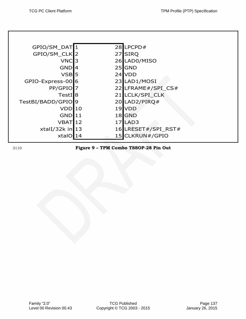
TCG PC Client Platform TPM Profile (PTP) Specification
Family “2.0” TCG Published Page 137 Level 00 Revision 00.43 Copyright © TCG 2003 - 2015 January 26, 2015
GPIO/SM_DAT 1 28 LPCPD#
GPIO/SM_CLK 2 27 SIRQ
VNC 3 26 LAD0/MISO
GND 4 25 GND
VSB 5 24 VDD
GPIO-Express-00 6 23 LAD1/MOSI
PP/GPIO 7 22 LFRAME#/SPI_CS#
TestI 8 21 LCLK/SPI_CLK
TestBI/BADD/GPIO 9 20 LAD2/PIRQ#
VDD 10 19 VDD
GND 11 18 GND
VBAT 12 17 LAD3
xtalI/32k in 13 16 LRESET#/SPI_RST#
xtalO 14 15 CLKRUN#/GPIO
Figure 9 – TPM Combo TSSOP-28 Pin Out 3110

TPM Profile (PTP) Specification TCG PC Client Platform
Page 138 TCG Published Family “2.0” January 26, 2015 Copyright © TCG 2003 - 2015 Level 00 Revision 00.43
GN
D
VN
C
VN
C/G
PIO
VN
C/G
PIO
NC
NC
NC
NC
32 31 30 29 28 27 26 25
VDD/VSB 1 24 MISO
GND 2 23 GND
GPIO 3 22 VDD
GPIO 4 21 MOSI
NC 5 20 SPI_CS#
VNC/GPIO 6 19 SPI_CLK
GPIO/VDD 7 18 SPI_PIRQ#
VDD 8 17 SPI_RST#
9 10 11 12 13 14 15 16GN
D
VN
C
NC
NC
VN
C/G
PIO
VD
D
NC
GN
D
VQFN 32 pin
5mm x 5mm
Figure 10 —TPM SPI QFN-32 Pin out
4. Using the pin-out defined in Figure 9 TPM Combo TSSOP 28 Pin Out, the pins SHALL be assigned as defined in Table 47. Using the pin-out defined in Figure 10, the pins SHALL be assigned as defined in Table 48.
The pins which are marked “M” for “mandatory” in Table 47 and Table 48 are required 3115
to be implemented. Those which are marked “O” for “optional” are not required for claims of adherence, but if implemented, must be implemented per Table 47 and Table 48.

TCG PC Client Platform TPM Profile (PTP) Specification
Family “2.0” TCG Published Page 139 Level 00 Revision 00.43 Copyright © TCG 2003 - 2015 January 26, 2015
Table 47 — TSSOP-28 Pin Assignments
Signal Pin(s) Type Description LPC pin-assignments
SPI pin-assignments
LAD3 17 BI As defined in the LPC Interface Specification
M O
LAD2/PIRQ 20 BI/O
LAD 2: As defined in the LPC Interface Specification
PIRQ#: SPI Interrupt, active low, open collector
LAD2 – M PIRQ#-M
LAD1/MOSI 23 BI
LAD1: As defined in the LPC Interface Specification
MOSI: As defined in Section 6.4 SPI Hardware Protocol
M MOSI-M
LAD0/MISO 26 BI LADO: As defined in the LPC Interface Specification
M MISO-M
LPCPD# 28 I Implementation of this pin SHALL allow for the pin to be strapped HIGH.
O O
LCLK/SPI_CLK 21 I
LCLK: As defined in the LPC Interface Specification.
SPI_CLK: As defined in Section 6.4.1 Clocking
LCLK-M SPI_CLK-M
LFRAME#/SPI_CS# 22 I
LFRAME#: As defined in the LPC Interface Specification
SPI_CS#: As defined in Section 6.4 SPI Hardware Protocol
LFRAME-M SPI_CS#-M
LRESET#/SPI_RST# 16 I
LRESET#: As defined in the LPC Interface Specification
SPI_RST#: Active Low
LRESET#-M SPI_RST#-M
SERIRQ 27 BI As defined in the LPC Interface Specification
M O
CLKRUN#/GPIO 15 BI
Same as PCI CLKRUN#. Active Low, internal pull-down. Only needed by peripherals that need DMA or bus mastering in a system that can stop the PCI bus (generally mobile devices). Implementation of CLKRUN# is TPM and chipset vendor specific GPIO will default to low.
O O
PP/GPIO 7 I,BI
Physical Presence, active high, internal pull-down. Used to indicate Physical Presence to the TPM. GPIO will default to low
O O
XTALI/32k in 13 I 32 kHz crystal input or 32 kHz clock input
O O
XTALO 14 O 32 kHz crystal output O O
GPIO/SM_CLK 2 BI
Defaults as a GPIO. GPIO will default high.
Also used as System Management Bus (SMB) Clock signal
O O
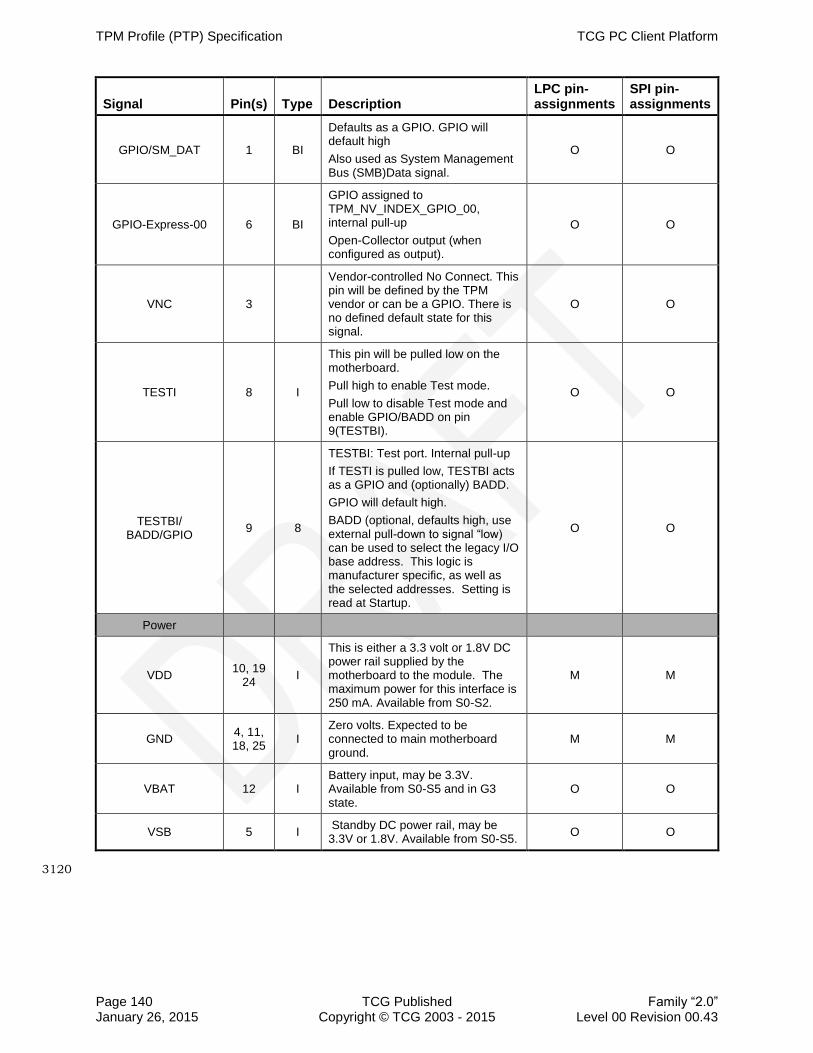
TPM Profile (PTP) Specification TCG PC Client Platform
Page 140 TCG Published Family “2.0” January 26, 2015 Copyright © TCG 2003 - 2015 Level 00 Revision 00.43
Signal Pin(s) Type Description LPC pin-assignments
SPI pin-assignments
GPIO/SM_DAT 1 BI
Defaults as a GPIO. GPIO will default high
Also used as System Management Bus (SMB)Data signal.
O O
GPIO-Express-00 6 BI
GPIO assigned to TPM_NV_INDEX_GPIO_00, internal pull-up
Open-Collector output (when configured as output).
O O
VNC 3
Vendor-controlled No Connect. This pin will be defined by the TPM vendor or can be a GPIO. There is no defined default state for this signal.
O O
TESTI 8 I
This pin will be pulled low on the motherboard.
Pull high to enable Test mode.
Pull low to disable Test mode and enable GPIO/BADD on pin 9(TESTBI).
O O
TESTBI/ BADD/GPIO
9 8
TESTBI: Test port. Internal pull-up
If TESTI is pulled low, TESTBI acts as a GPIO and (optionally) BADD.
GPIO will default high.
BADD (optional, defaults high, use external pull-down to signal “low) can be used to select the legacy I/O base address. This logic is manufacturer specific, as well as the selected addresses. Setting is read at Startup.
O O
Power
VDD 10, 19
24 I
This is either a 3.3 volt or 1.8V DC power rail supplied by the motherboard to the module. The maximum power for this interface is 250 mA. Available from S0-S2.
M M
GND 4, 11, 18, 25
I Zero volts. Expected to be connected to main motherboard ground.
M M
VBAT 12 I Battery input, may be 3.3V. Available from S0-S5 and in G3 state.
O O
VSB 5 I Standby DC power rail, may be 3.3V or 1.8V. Available from S0-S5.
O O
3120

TCG PC Client Platform TPM Profile (PTP) Specification
Family “2.0” TCG Published Page 141 Level 00 Revision 00.43 Copyright © TCG 2003 - 2015 January 26, 2015
Table 48 — QFN-32 Pin Assignments
Signal Pin(s) Type Description SPI pin-
assignments
SPI_PIRQ# 18 BI/O
PIRQ#: SPI Interrupt, active low, open collector
M
SPI_CLK 19 I SPI_CLK: As defined in Section 6.4.1 Clocking M
SPI_CS# 20 I
SPI_CS#: As defined in Section 6.4 SPI Hardware Protocol
M
SPI_RST# 17 I SPI_RST#: Active Low M
GPIO 3, 4 BI GPIO defaults to low. O
VNC/GPIO 6, 13, 29, 30
I,BI Vendor defined no-connect. GPIO will default to low
O
MOSI 21 BI
MOSI – As defined in Section 6.4 SPI Hardware Protocol
M
MISO 24 BI
MISO – As defined in Section 6.4 SPI Hardware Protocol
M
VNC 10, 31
Vendor-controlled No Connect. This pin will be defined by the TPM vendor or can be a GPIO. There is no defined default state for this signal.
O
Power
VDD
14 22 I
This is a either a 3.3 volt or 1.8 volt DC power rail supplied by the motherboard to the module. The maximum power for this interface is 250 mA. Available from S0-S2.
M
VDD/VSB
1 I
This is a either a 3.3 volt or 1.8 volt DC power rail supplied by the motherboard to the module. The maximum power for this interface is 250 mA. Available from S0-S2. If defined as VSB, this is a 3.3V supply.
M
GND 2, 9, 16, 23, 32
I Zero volts. Expected to be connected to main motherboard ground.
M
NC 5, 11, 12, 15, 25, 26, 27, 28
No connect
O
GPIO/Power 7 I
GPIO defaults to low, e.g. Physical Presence
Power is vendor defined O
6.7.2 Hardware Implementation of a TPM in a PC Client Platform
The TPM in the PC Client platform serves as the Root of Trust. As such, the hardware implementation of the TPM on the motherboard has to account for how the TPM is 3125
connected to the other components of the platform which form the trust chain, such as the CPU. It is important that the TPM reset, clock and power signals support the TPM’s function as the RTM and RTR and cannot be easily circumvented. Motherboard manufacturers should take care to ensure that the physical connections and routing minimize the possibility of attacking the S-CRTM and DRTM. 3130
1. The _TPM_INIT (LRESET#/SPI_RST#) signal SHALL be connected to the platform CPU Reset signal such that it complies with the requirements specified in Section

TPM Profile (PTP) Specification TCG PC Client Platform
Page 142 TCG Published Family “2.0” January 26, 2015 Copyright © TCG 2003 - 2015 Level 00 Revision 00.43
1.2.7 HOST Platform Reset in the PC Client Implementation Specification for Conventional BIOS.
2. The TPM’s main power pins (VDD) SHALL be connected such that the TPM is 3135
powered during ACPI states S0-S2 and MAY be powered in S3-S5.
3. If a TPM implements the optional VBAT and/or VSB pins, the pins MAY be connected to a battery or auxiliary power source. The motherboard manufacturer SHOULD consult their TPM documentation.
4. If a LPC TPM is implemented using the recommended packaging in Table 47, the 3140
TPM’s LPC bus SHALL be connected as defined in the LPC Specification, except as follows:
a. If the LPCPD# power down protocol is not implemented in both the chipset and the TPM, the LPCPD# pin on the TPM SHALL be strapped HIGH.
b. If the LPCPD# power down protocol is implemented in both the chipset and the 3145
TPM, the LPCPD# pin MAY be strapped HIGH.
c. CLKRUN# MAY be strapped HIGH to disable the TPM’s CLKRUN# protocol.
Note: If the TPM does not implement a pin for CLKRUN#, it is assumed to support the host disabling the LPC clock without changing the TPM state.
5. If an SPI TPM is implemented using the recommended packaging as defined in 3150
Figure 10 and Table 48, the TPM’s SPI bus SHALL be connected so that:
a. The TPM has a dedicated chip select (SPI_CS#).
b. The TPM’s SPI_RST# is connected directly to the platform’s RST#, so that it cannot be controlled independently of the south bridge asserting CPU_RST#.
6. An SPI TPM SHALL be implemented in a platform such that is only accessed, via 3155
asserting SPI_CS#, if an MMIO access to 0xFED4xxxx is received by the chipset.
Note: Locality 4 accesses to the hardware hash registers may be accessed via an implementation specific mechanism other than MMIO, but these accesses still obey this rule by virtue of being in the TPM’s address range.
7. The Platform SHALL provide a hardware mechanism, e.g. a hardware-based strap, 3160
to configure the platform’s TPM and chipset to support the SPI interface.
6.7.2.1 SPI Platform Design Notes
This section provides guidelines for platform OEM’s and ISV’s to aid in design of platforms and software using an SPI TPM. The following sections are informative only, as they describe recommended behavior. 3165
6.7.2.2 SW Interface to SPI-TPM
The SPI interface has been architected to be transparent to the driver and application layers in a TPM-enabled software stack. There are some SPI properties which will produce different results than LPC in cases where software does not follow good design practice. In these cases, this specification addresses the TPM requirements so that 3170
none of the TPM’s security is impacted by bad software design, at the risk of a potentially poor user experience. As such, software and drivers should follow these recommendations to ensure a robust implementation.
TCG PC Client Platform TPM Profile (PTP) Specification
Family “2.0” TCG Published Page 143 Level 00 Revision 00.43 Copyright © TCG 2003 - 2015 January 26, 2015
SW should continue to use the memory mapped 0xFED4_xxxx address range to access the SPI-TPM. 3175
Note: This is the same address range as for the LPC-TPM.
All existing LPC-TPM code will continue to work as is with the SPI-TPM
SW which uses legacy LPC cycles to the TPM will not work with an SPI TPM.
The SPI TPM has added an extended data FIFO for larger data transfers. Software may or may not use this new register. 3180
Software should continue to use the existing protocols for accessing the TPM as described in Sections 5.5.2.4 and 5.5.2.5.
6.7.2.3 SW Command Interface to SPI-TPM
Many platforms support FLASH components on SPI by allowing SW to program a
command-based interface. SW sets up specific commands such as block write, erase, 3185
etc. through some platform dependent set of registers.
Note: some platforms may choose to not have a TPM as part of the platform, or continue to use the LPC-TPM. Those platforms may use the SPI-TPM CS# for additional FLASH space or some other usage. In that case the command-based accesses may be allowed. The mechanism to determine whether the CS# is attached to 3190
a TPM must not be SW dependent but should be some HW mechanism fixed by the OEM at manufacturing.

TPM Profile (PTP) Specification TCG PC Client Platform
Page 144 TCG Published Family “2.0” January 26, 2015 Copyright © TCG 2003 - 2015 Level 00 Revision 00.43
7 References
1. The Trusted Computing Group: http://www.trustedcomputinggroup.org
2. Low Pin Count (LPC) Interface Specification: 3195
http://www.intel.com/design/chipsets/industry/lpc.htm
3. PC Specific Implementation Specification: http://www.trustedcomputinggroup.org/developers/pc_client/specifications
4. System Management Bus (SMBus) Specification Version 2.0: http://www.smbus.org 3200
5. PCI Express Electromechanical Specifications: http://www.pcisig.com
6. The Serial IRQ (SERIRQ) protocol definition: http://www.smsc.com/ftpdocs/papers.html
7. TPM Library Specification: http://www.trustedcomputinggroup.org/developers/trusted_platform_module/spe3205
cifications


![I C A Work in Progress - Trusted Computing Group€¦ · [2] TCG TSS 2.0 TPM Command Transmission Interface (TCTI) API Specification [3] TCG TSS 2.0 Marshaling/Unmarshaling (MU) API](https://img.dokumen.tips/doc/110x75/5ec89d72b531cf0b9b5a4ed3/i-c-a-work-in-progress-trusted-computing-group-2-tcg-tss-20-tpm-command-transmission.jpg)