Embed Size (px)
DESCRIPTION
TC status , June 20th, 2006 . F.Gatti UNIVERSITY and INFN of Genoa, Italy. APD Cooled Support. TC Final Design. APD F.E. Board. Scintillating Fibers (Phi Counter). Item to be designed. Item prototyped & method of constr tested Item ready. - PowerPoint PPT Presentation
Citation preview
1
TC status, June 20th, 2006 .
F.GattiUNIVERSITY and INFN
of Genoa, Italy

2
TC Final Design• A PLASTIC SUPPORT STRUCTURE ARRANGES THESCINTILLATOR BARS AS REQUESTED
• THE BARS ARE GLUED ONTOTHE SUPPORT
• INTERFACE ELEMENTS ARE GLUED ONTO THE BARS AND SUPPORT THEFIBRES
• FIBRES ARE GLUED AS WELL
• TEMPORARY ALUMINIUM BEAMS ARE USED TO HANDLE THE DETECTOR DURING INSTALLATION
• PTFE SLIDERS WILL ENSUREA SMOOTH MOTION ALONG THE RAILS
PM-Scintillator Coupling
Scintillator Housing
BC404-Scintillator slab
Main Support
ladder Board& cabling
PM
APD
APD F.E. BoardScintillating Fibers (Phi Counter)
APD Cooled Support
Item to be designed. Item prototyped & method of constr tested Item ready.

3
The Z detector of “Up Stream” TC is fully tested

4
Further improvement in the scintillating detectors light yield• The attenuation length of the scintillating fiber is in disagreement with the producer specifics: a single exponential
decay is claimed with λ> 3.5 m. Measurements made ion the light yield vs distance show two exponential decays (λ1=0.2 m and λ2=2.6m) .
• We have excluded that this can be attribute to self-absorption effect in the sicntillating core: the emission spectrum is independent to the path lenght (i.e. fiber lenght)
• We concluded that most of the light is lost in few tants of cm by the external cladding: impurities and/or not-uniform claddinglayer
Bicron data
Measured emission spectrum

5
Expected Measured
Emission spectrum peak 492 nm 498.5 ± 2.0 nm
Attenuation length > 3.5 m X1= 22.3 ± 2.3 cm X2= 260 ± 15 cm
Cladding-core ratio
coreL
aircladdingLR
.
)(.
1.37 1.44 ± 0.18
Trapping efficiency without EMA 7.3% 6.6 ± 0.5 %
Trapping efficiency with EMA Not available 5.7 ± 0.4 %
Light efficiency loss final design Not available 26 ± 2 %
Efficiency loss annealing process 120°C Not available Below instruments sensitivity
Summary of the measurements on the fibersSummary of the measurements on the fibers
(BICRON)

6
Ligth recovered by coating with white reflector
Fiber with white reflectance coating(99.3%,lambertian – Kodak #6080)
Sr-90 source and coincidence detectorto tag the electrons that pass through
the full thickness of the fiber
APD read-out electronics
• Signal to noise is improved by 50-80%. • The overall light trapping efficiency has been improved by using high quality white reflectance coating
(99.3% @ 500 nm)
55 cm
20 cm
Signal spectrum of SR90 electrons

7
N2 bag under construction
Raw Material Gluing…
…to provide the right dimension
MachiningFinal pieces

8
The EVAL plastics is ready to be formed
PP-EVALT-PP under test before to be formed
9
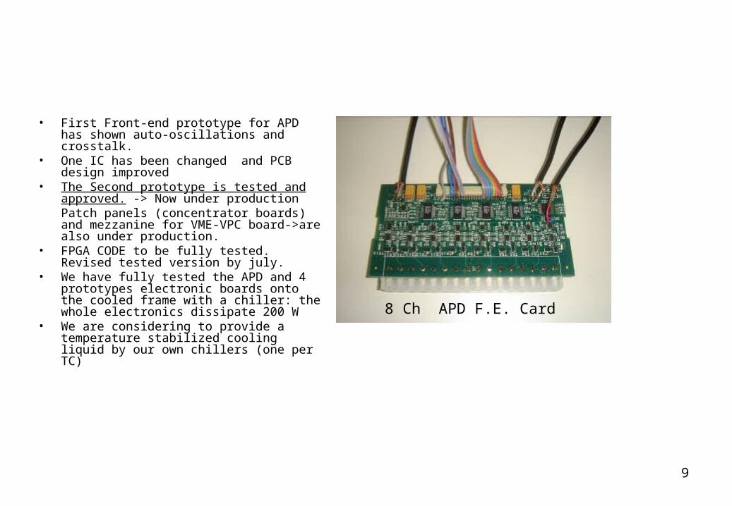
• First Front-end prototype for APD has shown auto-oscillations and crosstalk.
• One IC has been changed and PCB design improved
• The Second prototype is tested and approved. -> Now under productionPatch panels (concentrator boards) and mezzanine for VME-VPC board->are also under production.
• FPGA CODE to be fully tested. Revised tested version by july.
• We have fully tested the APD and 4 prototypes electronic boards onto the cooled frame with a chiller: the whole electronics dissipate 200 W
• We are considering to provide a temperature stabilized cooling liquid by our own chillers (one per TC)
8 Ch APD F.E. Card

10
Discriminator and splitter board

11

12

13

14

15
Status of the schedule• Test @ BTF:
– -> Jan 27/Feb 3: test of final bar– March 27/April 3 (TC#1): test of only Z-counter of TC#1– June 26 /july 3 (TC#1 & TC#2)
• Delivery at PSI: -> TC#1 July, 24th ; TC#2, July 30th. • PM:
– Selection by -> may, 30th– ladder socket -> ready– Discr./splitter: prototype and timing analysis tested.– Production: ?
• APD electronics: – First prototypes ready: Jan,15th (problems with IC and Croos-talk) – Second prototype ready and tested:( changed IC and PCB design) May, 12th.– Final production: -> July 15th -> june 30th– FPGA SW (first Vers.) Jan,15th, final version after TC test: Jul, 15th.
• TC bag: – design ready, material ready.– Construction: june 1 st – 30 th– delivery, ->July 18th.
• Laser:– Design ready.– Components order and procurement: may 30th -> june 30th– 50 fibers, low time jtter (10 um), and fiber-injector already ordered.– Delivery: after 3 months from the procurement ( Sept, 31th)
• He Monitor system (-> July, 18th)