Embed Size (px)
Citation preview
TASER®
AXON flex® SystemUser Manual
The most up-to-date warnings and instructions are available at www.TASER.com.
IMPORTANT SAFETY INSTRUCTIONS.Read all warnings and instructions. Save these instructions.
MMU0040 Rev: D

2
Contents
3 Chapter 1: Introduction 3 What Is the AXON flex System? 3 Additional Reading
4 Chapter 2: Hardware 4 AXON flex Features 4 AXON flex Camera 4 AXON flex Controller 6 Equipment Mounting Options 6 AXON flex Cables and Connectors 6 Straight-to-Right-Angle Connector 6 USB Cable
8 Chapter 3: Hardware Details 8 Preparing the AXON flex Camera10 Preparing the Magnetic Clip Assembly11 Mounting the flex Camera to Your Shirt Collar
12 Chapter 4: Basic Operations12 Operating Modes12 BUFFERING Mode13 EVENT Mode13 Battery Status13 Adjusting the Audio Prompt Volume14 Turning off the Controller LEDs
15 Chapter 5: Audio Prompts
16 Chapter 6: Care and Maintenance16 Cleaning the AXON flex System Components16 Charging the Controller Battery
17 Chapter 7: Troubleshooting17 Reset Functioning17 Customer Service17 Warranty Policy17 Warnings18 Radio Waves18 CE Declaration of Conformity
3
What Is the AXON flex System?
The AXON flex® system is a camera system incorporating an audio and video recording device to be worn by you while performing your job duties. Multiple mounting options are available to customize the system to your needs. The components are designed for use in tough environmental conditions. The system is designed to record events in real time for secure storage, retrieval, and analysis via the EVIDENCE.com website or in an Offline configuration to your local computer. The recorded events are transferred to your storage solution via the evidence transfer manager (ETM), the EVIDENCE.com Dock, or by using EVIDENCE Sync software installed on a Windows computer.
The system has two operating modes. The default mode, or BUFFERING mode, provides pre-event buffering to capture activities that occur prior to the user activating the EVENT mode. In addition, the AXON® Mobile application enables playback of footage on a smart phone for review prior to storing the data.
Instructional videos for using your AXON flex system are available at www.TASER.com under Training Videos.
Additional Reading
This manual explains how to operate the AXON flex hardware. Other manuals cover additional aspects of the AXON flex system. These documents are available at www.TASER.com.
The TASER AXON System End-to-End Deployment Guide explains how to register for the EVIDENCE.com website, configure settings, install EVIDENCE Sync software, assign personnel to cameras, recharge your controller, and transfer video from an AXON device to a computer.
Detailed instructions for using AXON cameras and other TASER products with EVIDENCE Sync are available in the EVIDENCE Sync User Manual.
For instructions on using your AXON flex camera with a smart device, see the AXON Mobile for Android Devices User Manual or the AXON Mobile for IOS Devices User Manual, as appropriate.
If you have an EVIDENCE.com Dock, see the EVIDENCE.com Dock User Manual for how to transfer information and recharge your controller.
Introduction 1

4
AXON flex Features
The primary AXON flex components are the camera and controller.
AXON flex Camera
The camera offers high quality video and low-light gathering capabilities. The camera is designed to store at least 4 hours of video (and up to 13 hours based on the video setting). If the camera is full (has reached its storage limit), the camera will not record over previous video but instead stops recording.
Volume/Pairing Button
Imager
Bracket Clip
1 Volume/Pairing Button – This button is used to adjust the volume of audio prompts coming from the camera. It also is used to pair the AXON flex system with a smart phone; see the AXON Mobile for Android Devices or AXON Mobile for IOS Devices manuals for more information. This button does not control the volume of recorded audio.
2 Bracket Clip – A clamp attaches to this part of the camera, and the clamp can be attached to a variety of mounting tools.
3 Imager – This is the camera lens. Avoid touching the lens. For cleaning information, see Chapter 5 Care and Maintenance in this manual.
AXON flex Controller
The controller enables you to turn the unit on, begin recording of an event, stop recording, and turn the unit off. The controller features LEDs to indicate the operating mode and battery capacity.
Hardware 2

5Chapter 2 Hardware
NOTE: You can turn off the controller LEDs, if necessary. See Turning off the Controller LEDs in this manual for instructions.
Top View
Front View
Operation LEDOn/Off Indicator
EVENT Button
Battery LED
Battery Button
On/Off Switch
1 Operation LED – Shows the controller’s current operating mode:
Operating Mode Controller LED
Recording Blinking red
Buffering Blinking green
Booting up/powering down Solid red
Disconnect Blinking yellow
NOTE: For the battery status, see the battery LED, described below.
2 On/Off Switch – Turns the controller on or off.
3 On/Off Indicator – When the controller is turned on, the red portion of the controller is exposed. When the controller is turned off, the red portion is covered from view.
4 EVENT Button – Used to start and stop recording. (Double-press to start; hold for 3 seconds to stop recording.)The controller might take several additional seconds to close out of the event video when it is taken out of EVENT mode.
5 Battery Button – When pressed, momentarily indicates the remaining battery capacity only (it does not indicate the operating mode).
6 Battery LED – When pressed, momentarily indicates the remaining battery capacity only (it does not indicate the operating mode).

6 Chapter 2 Hardware
Battery Capacity Battery LED
Battery capacity is 41–100 percent Green
Battery capacity is 20–40 percent Yellow
Battery capacity is less than 20 percent Red during operation; flashing red and yellow during charging
Battery critically low Blinking red and yellow
When you turn the controller on, all LED lights turn solid red until the system is ready to use. Then the Operation LED blinks green (BUFFERING mode) and the Battery LED goes out.
Equipment Mounting Options
The AXON flex system provides you with a variety of ways to wear your camera and carry your controller. Multiple holster options are available to attach the controller to your shirt or belt; and a variety of mounts enable the camera to be attached to your Oakley Flak Jacket eyewear, shirt collar or epaulet, load bearing equipment, helmet, cap, or your vehicle’s dashboard.
Additional information on AXON flex mounting options is available at www.TASER.com.
AXON flex Cables and Connectors Straight-to-Right-Angle Connector
The AXON flex camera and controller are designed to work with a purpose-built cable, with a straight connector at one end and a right-angle connector at the other. Insert the straight connector into the camera and the right-angle connector into the controller. The straight connector has jaws designed to grasp camera for added security. The controller holster has a swing arm designed to fit over the connecter and help keep it in place.
These cables are specifically calibrated to work with the AXON flex system. Use of unapproved cables will degrade system performance and may cause the system to not function properly or at all.
Ensure that your cables are inserted properly into the camera and controller. If the camera’s battery is low, or the cable is disconnected, your recorded video will be lost.
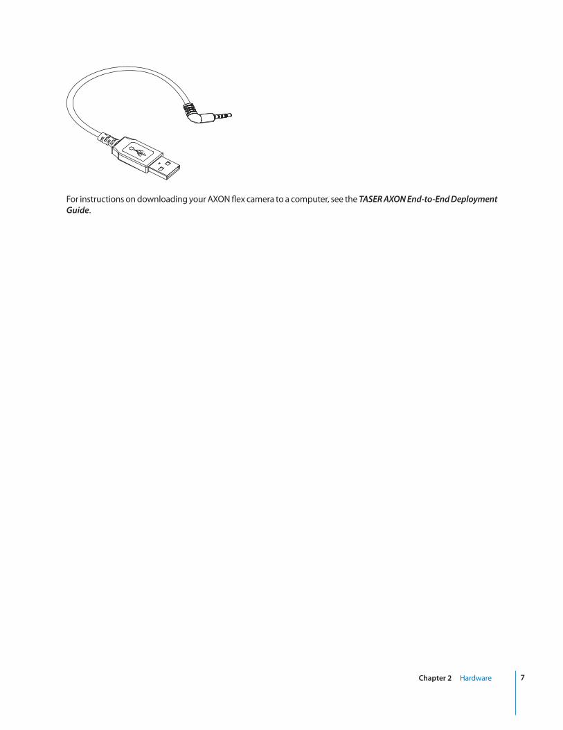
USB Cable
A USB cable is available to connect the AXON flex camera directly to your computer.
Do NOT connect your AXON flex camera to your computer before you have installed the EVIDENCE Sync software.
7Chapter 2 Hardware
For instructions on downloading your AXON flex camera to a computer, see the TASER AXON End-to-End Deployment Guide.
8
Hardware Details 3
This chapter describes preparing and using the universal magnetic mount. For additional information on using the universal mount and other mounts, see the instructional videos for assembling AXON flex hardware at www.TASER.com.
If the camera system causes discomfort or headaches, adjust the system for comfort. NEVER wrap cables around the neck.
The AXON flex system uses magnets in many of its mounting systems. The AXON flex camera and AXON flex controller both contain batteries. Do not let the magnets come into contact with the batteries. Magnets can cause damage to the batteries.
Preparing the AXON flex Camera
All AXON flex cameras shipped from the factory are configured to be installed on the right side of the body. If you wish to wear a camera on the left side, you will have to adjust your settings through the EVIDENCE Sync software or on the EVIDENCE.com website to re-orient the camera.
The side on which you wear the camera is configured through the EVIDENCE Sync software. Try wearing your camera on your dominant side and your non-dominant side to find what works best for you. If you have the AXON Mobile application, you can view live video and determine if the camera is pointed where you want it. See the AXON Mobile for Android Devices or AXON Mobile for IOS Devices manuals for more information on how to do this.
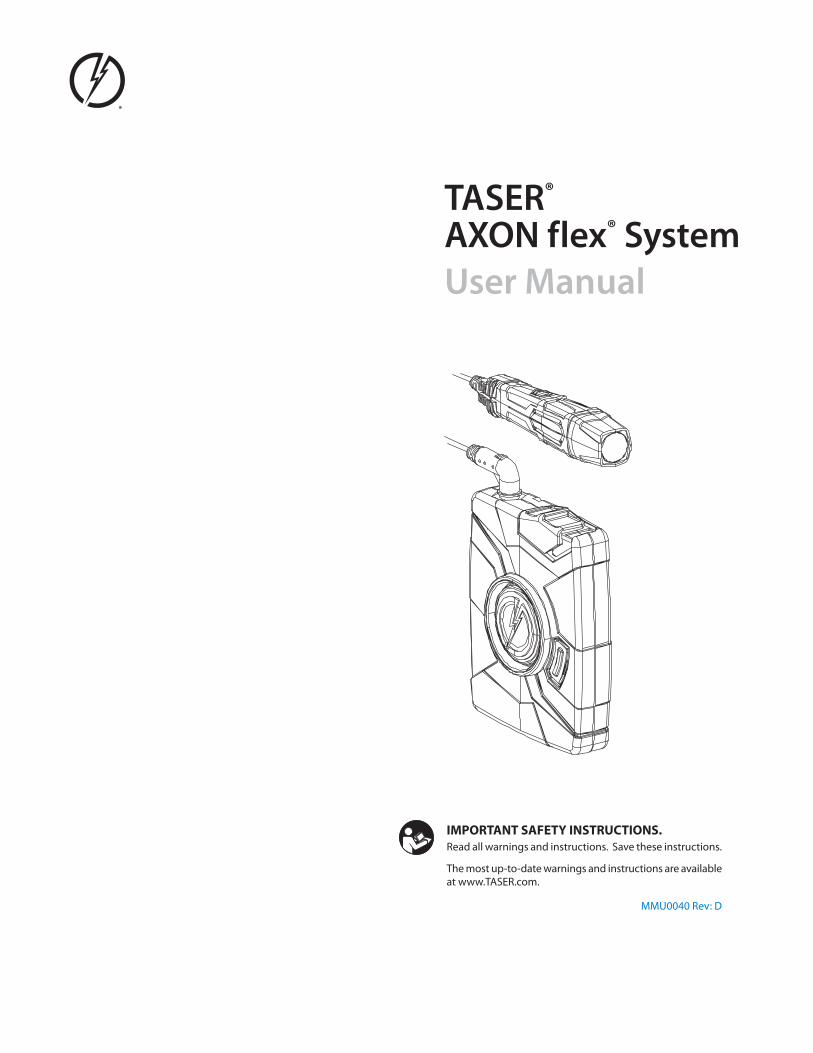
Cable connectors are inserted into the rear of the AXON flex camera. The connector has an assembly that clasps to the camera for a more secure fit. Both straight and coiled cables are also available.

9Chapter 3 Hardware Details
To Controller
To Camera
The AXON flex camera has a circular bump on one side, at the rear of the camera. The cable connector has a round opening that fits around the bump, providing added security when connected.
Opening in Connector Protruding Bump on Camera
If you do not connect the cable to the camera properly, the connection may not be secure.
The controller holster has a cable retention clip that rolls into place to help keep the cable attached.
10 Chapter 3 Hardware Details
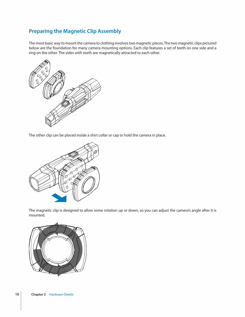
Preparing the Magnetic Clip Assembly
The most basic way to mount the camera to clothing involves two magnetic pieces. The two magnetic clips pictured below are the foundation for many camera mounting options. Each clip features a set of teeth on one side and a ring on the other. The sides with teeth are magnetically attracted to each other.
The other clip can be placed inside a shirt collar or cap to hold the camera in place.
The magnetic clip is designed to allow some rotation up or down, so you can adjust the camera’s angle after it is mounted.

11Chapter 3 Hardware Details
Mounting the flex Camera to Your Shirt Collar
1 Push the two parts of the universal magnetic clip together on each side of your collar.
2 Tug on the parts slightly to confirm the connection is secure.
3 Attach the camera assembly to the magnetic clip on the outside of your shirt.
4 Tug on the parts slightly to confirm the connection is secure.
5 Route the cable to your controller. Ensure that the cable does not obstruct the motion of your head.

12
4
Operating Modes
The AXON flex system has two operating modes:
1 BUFFERING
2 EVENT
BUFFERING Mode
BUFFERING mode is the default mode of operation, and it is activated a few seconds after turning on the controller. The camera must be attached to the controller in order for it to capture video in BUFFERING mode. If the camera is not connected to the controller, you will not capture any video.
When BUFFERING begins:
• The Operation LED on the controller will blink green.
• The camera will be capturing video but no audio, and will not record to permanent memory while in BUFFERING mode.
• Buffered video duration is up to 30 seconds (00:00:30).
When you activate the EVENT mode, the buffered video (not audio) captured directly before the event will be saved and attached to the event in permanent memory. This feature is intended to capture the video of an incident just before your activation of EVENT mode.
Because the system does not capture audio in BUFFERING mode, the first 30 seconds of a recorded event will be video-only. Buffering mode starts only after the AXON flex controller is turned on. The system does not record when the controller is turned off.
NOTE: An agency can turn off the BUFFERING mode. If your agency has deactivated the BUFFERING mode, your AXON system will operate the same way as described in this manual, but the camera will not record anything until you double-press the EVENT button.
EVENT Mode
1 When you need to record, quickly double-press the EVENT button on the controller.
The system now records audio as well as video. The “buffered” video directly preceding the event will be saved
Basic Operations

13Chapter 4 Basic Operations
and attached to the event recording. (Remember, the buffered video will not contain audio.)
The moment you double-press the EVENT button, both video and audio will be recorded from the camera and GPS coordinates (if the system is paired to a GPS-capable smart phone) will be recorded. This will continue throughout the duration of the recording until you terminate the recording.
The AXON flex hardware provides you with indications that it is recording in EVENT mode:
• At the start of an event and every 2 minutes during an event, the system will beep twice.
• The Operation LED on top of the controller will blink red.
The camera must be attached to the controller in order for it to record video in EVENT mode. If the camera is not connected to the controller, you will not record any video. If the camera becomes disconnected from the controller during an event, the system will stop recording.
2 To stop recording and return to BUFFERING mode, press the EVENT button for approximately 3 seconds. The system will beep once.
3 To end a recording and turn off the system, move the on/off switch to the “off” position. When you end a recording with the on/off switch you will not go into BUFFERING mode; instead the system will turn off completely.
NOTE: An event not recorded by the AXON flex system cannot be played back or downloaded to your computer.
Battery Status
Press the Battery button to determine the percentage remaining in the controller battery. See AXON flex Controller in Chapter 2 Hardware in this manual for details on the Battery LED functions.
Adjusting the Audio Prompt Volume
Press the volume/pairing button on the camera to adjust the volume of the audio prompts.
Volume/Pairing Button
The volume has four settings. At each level, the camera beeps, providing you with a sample of the volume:
• Low
• Medium
• High
• Off

14 Chapter 4 Basic Operations
Other than the audio prompt beeps heard on the audio recordings, the volume/pairing button has no effect on the audio recording captured by the camera.
Turning off the Controller LEDs
For some situations, you may wish to turn off the lights on your controller.
1 Press and hold the Battery button for 10 seconds.
• The Operation LED flashes red, yellow, and then green before shutting down the lights.
• Pressing the Battery button will momentarily light both the Operation LED and the Battery LED, displaying the current operating mode and battery level. For interpreting the LED colors, see AXON flex Controller in Chapter 2: Hardware in this manual.
2 To turn the lights back on, press and hold the Battery button for 10 seconds.
If you disconnect a cable when the lights are active, the Operation LED flashes yellow. If you turned off the LEDs, and you later disconnect a cable, there will be no visual warning that the cable has been disconnected.
15
Audio Prompts
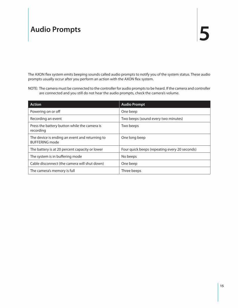
The AXON flex system emits beeping sounds called audio prompts to notify you of the system status. These audio prompts usually occur after you perform an action with the AXON flex system.
NOTE: The camera must be connected to the controller for audio prompts to be heard. If the camera and controller are connected and you still do not hear the audio prompts, check the camera’s volume.
Action Audio Prompt
Powering on or off One beep
Recording an event Two beeps (sound every two minutes)
Press the battery button while the camera is recording
Two beeps
The device is ending an event and returning to BUFFERING mode
One long beep
The battery is at 20 percent capacity or lower Four quick beeps (repeating every 20 seconds)
The system is in buffering mode No beeps
Cable disconnect (the camera will shut down) One beep
The camera’s memory is full Three beeps
5

16
Care and Maintenance
Cleaning the AXON flex System Components
Use a soft, damp cloth to clean the surface of the system components. Do not use harsh cleaners or solvents. Do not immerse the system components in water or cleaning solutions.
If the AXON flex camera lens becomes dirty, use a lens blower brush to clean it and then wipe it with a soft cloth if necessary.
You may moisten the cloth with isopropyl alcohol.
• Do not use Windex or similar type cleaners on the camera lens.
• Do not place the lens under running water or apply jets of water to the camera lens.
• When the cable contacts show signs of contamination (e.g., with dirt or debris), clean them gently with a white or red pencil eraser.
Charging the Controller Battery
A fully charged controller battery should provide enough power for approximately 12 hours of normal operation. Recharging a battery after a 12-hour use can take up to 6 hours if you are recharging your controller from a wall outlet, EVIDENCE.com Dock, or an ETM. Recharging could take considerably longer if you are recharging from a computer.
If the battery depletes significantly during the shift, you will hear 4 quick tones repeating every 20 seconds. This message indicates that less than approximately 20 percent of the battery capacity remains.
Always recharge a depleted battery as soon as reasonably possible. You can use an ETM, EVIDENCE.com Dock, wall charger, or computer (using the 2.5 mm to USB cable) to charge the battery. Using a non-TASER approved wall charger may degrade device performance.
Do not have EVIDENCE Sync open and running on your computer when recharging an AXON flex controller with a computer.
6

17
Troubleshooting
If you experience difficulty with your AXON flex devices, first power the device(s) down, disconnect the cables, and then reconnect the cables to ensure a proper connection.
If experiencing difficulty with the AXON Mobile application, power down the mobile device, turn the device back on, and re-pair your smart phone with the AXON flex camera. See the AXON Mobile for Android Devices User Manual or AXON Mobile for IOS Devices User Manual, as appropriate, for more information.
Do not plug an AXON flex controller into a computer with the EVIDENCE Sync software active.
Reset Functioning
You might experience a reset while operating the AXON flex camera. During a reset, the camera will shut down, restart, and return to the mode (BUFFERING or EVENT) in which it was operating before the reset occurred.
If a reset occurs in BUFFERING mode, the camera will beep once while shutting down. The LED will go from blinking green (BUFFERING mode) to blinking yellow, and then it will turn solid red. The LED will then cycle back through solid red (booting). The camera will then beep once, and the LED will blink green (BUFFERING). This will repeat until the AXON system is booted up.
If the reset occurs in the EVENT mode, the camera will beep once while shutting down. The LED will go from blinking red (EVENT mode) to blinking yellow, and then it will turn solid red. The LED will then cycle back through solid red (booting). The camera will then beep once, and the LED will blink green (BUFFERING) and then blink red (EVENT). This will repeat until the camera is booted up.
Customer Service
Visit www.TASER.com and view the Support options.
Warranty Policy
TASER International warranty provisions are applicable on all AXON flex system products. See TASER International’s website, www.TASER.com, for detailed warranty information.
Warnings
For a full list of the warnings associated with this product, see www.TASER.com.
7

18 Chapter 7 Troubleshooting
Radio Waves
Changes or modifications to the equipment not expressly approved by the manufacturer could void the product warranty and the user’s authority to operate the equipment.
Your wireless device is a radio transmitter and receiver. It is designed and manufactured not to exceed the emission limits for exposure to radio frequency (RF) energy set by the Federal Communications Commission (FCC) of the U.S. Government. These limits are part of comprehensive guidelines and establish permitted levels of RF energy for the general population. The guidelines are based on standards that were developed by independent scientific organizations through periodic and thorough evaluation of scientific studies. The standards include a substantial safety margin designed to assure the safety of all persons, regardless of age and health. Before a device model is available for sale to the public, it must be tested and certified to the FCC that it does not exceed the limit established by the government‐adopted requirement for safe exposure.
This equipment has been tested and found to comply with the limits for a Class B digital device, pursuant to part 15 of the FCC Rules. These limits are designed to provide reasonable protection against harmful interference in a residential installation. This equipment generates, uses and can radiate radio frequency energy and, if not installed and used in accordance with the instructions, may cause harmful interference to radio communications. However, there is no guarantee that interference will not occur in a particular installation. If this equipment does cause harmful interference to radio or television reception, which can be determined by turning the equipment off and on, the user is encouraged to try to correct the interference by one or more of the following measures:
• Reorient or relocate the receiving antenna.
• Increase the separation between the equipment and receiver.
• Connect the equipment into an outlet on a circuit different from that to which the receiver is connected.
• Consult TASER International Customer Service for help.
FCC/IC NOTICE: This device meets the body worn human exposure limits found in OET Bulletin 65, 2001, and ANSI/IEEE C95.1, 1992. Proper operation of this equipment according to the instructions found in this guide will result in exposure substantially below the FCC’s recommended limits. To comply with the FCC and ANSI C95.1 RF exposure limits, this device has been tested for compliance with FCC RF Exposure limits in the typical configuration. The radiated output power of this wireless device is far below the FCC radio frequency exposure limits.
RSS 210 Warning Statement: The installer of this equipment must ensure that the antenna is located or pointed such that it does not emit RF field in excess of Health Canada limits for the general population; consult Safety Code 6, obtainable from Heath Canada’s Web site www.hc‐sc.gc.ca/rpb.
THIS MODEL DEVICE MEETS THE GOVERNMENT’S REQUIREMENTS FOR EXPOSURE TO RADIO WAVES.
Declaration of Conformity
TASER International declares that this AXON flex system is in compliance with the essential requirements and other relevant provisions of Directive 1999/5/EC.
A copy of the original declaration of conformity can be found at www.TASER.com.

Product functions and specifications may change without notice and the actual product may vary from the illustrations in this manual.
Android is a trademark of Google, Inc., Flak Jacket is a trademark of Oakley, Inc., IOS is a trademark of Cisco Technology, Inc., and Windex is a trademark of S. C. Johnson & Son, Inc.
TASER, AXON, AXON flex, © and � are trademarks of TASER International, Inc., registered in the USA. All rights reserved.© 2014 TASER International, Inc.
MMU0040 Rev: D