Embed Size (px)
Citation preview

1
The Effect of a Simple Lateral Impulse on Kinetic Energy Projectiles in Flight
Bernard J. Guidos Gene R. Cooper
ARL-TR-2076 DECEMBER 1999
20000208 089 :
Approved f@ public release; distribution is unlimited.

_ c
,
.
The &dings in this report are not to be construed as an offkial Department of the Army position unless so designated by other authorized documents.
Citation of manufacturer’s or trade names does not constitute an official endorsement or approval of the use thereof.
Destroy this report when it is no longer needed. Do’not return it to the originator.
l I

Errata for ARL-TR-2076, "Effect of a Simple Lateral Impulse on KE Projectile Flight," by Bernard J. Guidos and Gene R. Cooper, Dec 1999
Page 19, Equation (67) is incorrectly typed as:
F " - M F = ?,*[h(s-s, +As,)-h(s-s , )]-3*[hf(s--s , +As,)-hl(s-s,)] Eq(67)
The correct equation is:
-* r.,
I f - P*
4 - = i [ h ( s - s, + As,) - h(s - s,)]-'[hf(s - s, + As,) - hf(s - s,)] Eq (67) As As
Page 20, Equation (69) is incorrectly typed as:
The correct equation is:
F = K,ne i41,n ei4f(s-so)
+ K2,ne '42 ,n e-j4f(s-so)
! ,
Army Research Laborat& Aberdeen Proving Ground, MD 21005-5066
.
ARL,-TR-2076 December I999
The Effect of a Simple Lateral Impulse on Kinetic Energy Projectiles in Flight
Bernard J. Guidos Gene R. Cooper Weapons & Materials Research Directorate
.
.
Approved for public release; distribution is unlimited.
i

Abstract
Existing analytical theory for quantifying the free-flight motion of non- rolling, statically stable projectiles is extended to include the effect of a simple lateral impulse applied during flight. The extended theory is based on the incorporation of generalized lateral translational and angular disturbances into the familiar equations of projectile free-flight motion. The applied disturbances are then modeled using specified mathematical forms, and the modified equations are solved to obtain the angular and translational motion of the projectile over the trajectory. The various components of the translational motion of the projectile are extracted and characterized. An idealized application is presented for a large caliber finned projectile, representative of the class of 120-mm long rod kinetic energy projectiles fired from the MlAl Abrams tank, subjected to a single lateral control impulse in flight. The analytical closed form solutions are validated against results obtained using a numerical trajectory simulation code that incorporates generalized guidance and control commands.
ii

ACKNOWLEDGMENTS
The authors gratefully acknowledge Mr. John H. Whiteside, U.S. Army Tank-automotive
Armament Command, for providing the technical review of the report; Dr. Mark F. Costello,
Oregon State University, for providing guidance in the use of the numerical trajectory simulation
code; and Drs. Peter Plostins, Paul Weinacht, and Mark L. Bundy, U.S. Army Research
Laboratory, for reviewing the report manuscripts.
.
. . . 111
,

INTENTIONALLY LEFT BLANK
iv

TABLE OF CONTENTS
1.
2.
3.
4.
5.
5.1 5.2
6.
7.
8.
9.
9.1 9.2 9.3
10.
LIST OF FIGURES ..........................................
LISTOFTABLES ...........................................
INTRODUCTION ...........................................
IDEALIZED KE PROJECTILE ..................................
LATERAL DISPLACEMENT, ANGULAR DEVIATION, AND JUMP .....
APPLIED FORCE AND MOMENT DISTURBANCES. ................
ANGULAR MOTION WITH SINGULAR IMPULSE ..................
Equation of Angular Motion. ....................................
Modal Parameters. ...........................................
TRANSLATIONAL MOTION WITH SINGULAR IMPULSE ............
ANGULAR MOTION WITH SQUARE IMPULSE. ...................
TRANSLATIONAL MOTION WITH SQUARE IMPULSE. .............
RESULTS .................................................
Case 1: No Impulse .......................................... Case 2: In-Plane Impulse. ......................................
Case 3: Out-of-Plane Impulse ...................................
CONCLUSION.. ...........................................
REFERENCES ..............................................
APPENDIX
A. List of Symbols. ..........................................
DISTRIBUTIONLIST ........................................
REPORT DOCUMENTATION PAGE ............................
I!%
vii
ix
1
1
3
4
9
9 14
16
19
20
22
22 23 26
28
31
33
39
43
V

INTENTIONALLY LEFT BLANK
vi

LIST OF FIGURES
Figure parre
1. 2. 3. 4.
5. 6. 7. 8. 9.
10. 11. 12.
Idealized KE Projectile and Lateral Jet .............................. 2
Components of Angular Deviation ................................
Square Wave Disturbance. ......................................
z
Coordinate Systems .......................................... 7
PitchAngleaandYawAnglefi .................................. 10
Illustration of Undamped Epicyclic Motion .......................... 13
Pitch Angle Versus Range, Case 1 ................................. 23
Vertical Displacement Versus Range, Cases 1 and 2 ..................... 24
Pitch Angle Versus Range, Cases 1 and 2 ............................. 26
Vertical Displacement Versus Range, Cases 1 and 3 ..................... 27
Horizontal Displacement Versus Range, Cases 1 and 3 ................... ,27
Pitch and Yaw Angles Versus Range, Case 3 .......................... 28
vii

INTENTIONALLY LEFT BLANK
. . . Vlll

LIST OF TABLES
Table &s
1. Idealized Projectile and Laterai‘Jet Parameters . . . . . . . . . . . . . . . . . . . . . . . . . 2
ix

INTENTIONALLY LEFT BLANK
X

.
THE EFFECT OF A SIMPLE LATERAL IMPULSE ON KINETIC ENERGY PROJECTILES IN FLIGHT
1. INTRODUCTION
The U.S. Army is developing precision-guided munition technologies to improve the
accuracy and extend the range.of its weapon systems. In-flight guidance and control of
munitions involve the application of lateral course correction maneuvers that alter the angular
and translational motions of the flight body. Such maneuvers are accomplished by applying one
or more sets of prescribed translational and/or angular disturbances to the projectile during flight.
These applied lateral disturbances can be delivered in a variety of ways, including fin/canard
deflections or laterally thrusting jets. Disturbances of comparatively short duration can be
characterized as impulsive and are of particular interest here.
In this report, a specific class of lateral impulsive disturbances is incorporated into the
equations of motion for a finned, long rod, kinetic energy (KE) projectile. The procedure leads to
closed form analytical solutions that show straightforward relationships to exist between the
applied impulsive disturbances and the projectile angular and translational motion. The analytical
expressions not only eliminate much of the computational overhead associated with the prediction
of impulsively guided projectile motion but also lead to a generalized framework with which to
analyze actual measured projectile motion or to design complex guidance and control maneuvers.
The objective here is to present the impulse model, incorporate it into the modified
equations of motion, and validate the results with a 6-degrees-of-freedom (DOF) numerical
trajectory simulation code that has guidance and control commands. Application is presented for
an idealized large caliber finned KE projectile subjected to a single, simple in-flight lateral
impulsive disturbance. Characterization is made of the projectile motion before and after the
application of the lateral impulsive disturbance for some representative cases.
2. IDEALIZED KE PROJECTILE
An idealized 120~mm finned KE projectile geometry is adopted to compare the analytical
results with those from a numerical trajectory simulation code. Figure 1 illustrates the idealized
projectile geometry. Table 1 shows the defining parameters of the projectile. The configuration
represents the current class of 120-mm armor-piercing, fin-stabilized, discarding sabot (APFSDS)
KE ammunition fired from the Abrams MlAl tank. These projectiles are commonly of large length-
to-diameter ratio, statically stable, damped, with low to moderate spin rates, launched in flat fire.
LATERAL JET
NORMAL FORCE CENTER OF GRAVITY CENTER OF PRESSURE WITHOUT JET
Figure 1. Idealized IE Proiectile and Lateral Jet.
Table 1. Idealized Proiectile and Lateral Jet Parameters
I Metric English I Rod Diameter, d 0.0254 m 0.08333 ft
Mass, m Length
Center of Gravity (CG) from Base Transverse Moment of Inertia, It
5.0 kg 0.8 m 0.5 m
0.2 kg-m2
11.023 Ibm 2.62467 ft 1.6404 ft
0.1475 125 slug-ft2 Pitching Moment Coefficient, CM~
Lift Force Coefficient, CL= Location of Lateral Jet Relative to CG, dF
Jet Impulse Magnitude, 71”
- 100 cal/rad 10 / rad 0.2 m 1 .O N-s
-100 cal/rad 10 I rad
0.6563 ft 0.2248 1 lbf-s
The projectile is assumed to be perfectly symmetrical. The aerodynamic pitch-plane center of
pressure is determined from the prescribed values of pitching moment coefficient CM~ and lift
force coefficient &. The projectile is prescribed to have a lateral impulse jet situated at an axial
2
location that would correspond to a location on the windshield, near the shoulder. The lateral
impulse jet is prescribed to have a total impulse of 1 N-s, typical of an off-the-shelf component.
3. LATERAL DISPLACEMENT, ANGULAR DEVIATION, AND JUMP
The target impact of tank-fired rounds has been traditionally characterized in terms of jump.
The jump associated with a particular shot can be defined using the nomenclature introduced in
Figure 2. The boresight line of fire (LOF) is established as the line connecting the center of the
muzzle and the visual aim point (boresight point) that would be obtained by a muzzle borescope.
The gravity drop is extracted separately from various data sources and is considered known. The
LOF and gravity drop together establish an aim point, from which the target impact point is
measured. The vector that connects the aim point and target impact point is considered here to be
the lateral displacement. The horizontal and vertical components of the lateral displacement are
Zr and Yr, respectively. The lateral displacement is converted into an angle, in units of radians,
when divided by range. This angle, denoted as g represents the total angular deviation of the
projectile from the intended flight path as measured from the muzzle, i.e.,
Eq (1)
in which 8, and 8, are the horizontal and vertical components, respectively. The unit vector 7
is oriented upward (along the positive Y axis in the figure), and the unit vector z is oriented to
the gunner’s right (along the positive 2 axis in the figure), and these physical orientations
constitute range coordinates as used in this report.
The angular deviation of the projectile is commonly discussed in flight dynamics theory
using complex notation (to be introduced subsequently) and denoted here as 8 . In the complex
notation to be used here, the vertical component is oriented along a real coordinate axis and the
horizontal component is oriented along an imaginary coordinate axis, i.e.,
with i equal to fi.
e”=e, +ie, Eq (2)
3

Y I UNIT VECTORS
TARGET RANGE =X,
&, = HORIZONTAL COMPONENTOFANGULAR DEVIATION
6” = VERTICAL COMPONENT OF ANGULAR DEVIATION
Figure 2. Components of Angular Deviation.
At typical engagement ranges, the angular deviation of tank-fired KE ammunition,
historically consisting of unguided projectiles, is, for practical purposes, constant. In that case,
the lateral displacement of the projectile is proportional to range and it can be said that the
angular deviation of the projectile at the target corresponds to the jump attributable to the tank
launch event. However, at these same typical ranges, the lateral displacement of apuziZed tank-
fired KE projectile is typically not proportional to range after a mid-flight course correction
maneuver is applied. As a result, the angular deviation of the projectile at the target is not likely
to correspond to the jump attributable to the tank launch event. These observations, supported by
the mathematical development to be presented subsequently, produce discussions herein that
focus on the lateral displacement and angular deviation of the projectile, rather than on the more
traditional quantity of jump.
4. APPLIED FORCE AND MOMENT DISTURBANCES
In free flight, the projectile is acted upon by a lateral impulsive disturbance. The
disturbance can be separated into a translational component (i.e., force) F and an angular
4

component (i.e., moment) iI? , both defined as functions of time. In range coordinates and vector
form they are
F = F(t) = F,I+ F$ W (2)
n?=ti(t)=M,~+M,~ Eq (3)
in which the usual right-hand rule applies to the moment components.
The forms of the lateral disturbances F and n? are completely general in actual projectile
flight. The approach introduced here specifies simple modeled forms of the impulsive
disturbances that can be extended and used in more advanced applications to model actual; more
generalized, disturbances. Two basic mathematical forms of applied impulsive disturbances are
of interest here. The first is a single, positive phase duration, unidirectional square wave
disturbance. The disturbance has the form
Eq (4)
in which the subscript 1 denotes one of any number of disturbances that could be modeled. The
orientation of the applied lateral disturbance is measured from the vertical direction in the earth-
fixed frame, is denoted @, , and is constant. The magnitude is Fl with the restriction *
F, =F,(t)=C,[h(t-t,+At,)-h(t-t,)] for t-AtIct<tl Eq (5)
in which Cl is a real constant and h(t - tl) is the Heaviside unit step function occurring at tl
(Lighthill 1958). The form of Fl is illustrated in Figure 3, and this form of applied disturbance
is henceforth simply referred to as a square disturbance. The disturbance creates intervals and
sub-intervals, also illustrated in Figure 3, with which motion parameters will eventually be
associated. Concurrently, the disturbance can be described in terms of distance along the flight
path, S, as illustrated.
The second form of impulsive disturbance considered here is a singular disturbance. A
specific form of the square disturbance, it is defined here in the same manner as the square
disturbance but with the additional restriction that At, = 0 .
5
( interval 0 , syb-interval: (. interval 1 ,
. >
t0 t, - A t, tl
SO sI - A sI SI
t or s
Figure 3. Square Wave Disturbance.
The singular disturbance is the most important form for representing actual disturbances.
First, it is the most basic form of an impulsive disturbance, forming a building block with which
to model more complicated impulses and motions. Second, it is the most mathematically simple
form with which to work.
The modeled force and moment disturbances are to be incorporated into the free-flight
equations of motion that are presented and solved by Murphy (1963) and McCoy (1998).
McCoy’s coordinate systems are adopted here and illustrated in Figure 4. The (7, 7, r) system
is the earth-fixed range system, the (i, j,E) system is a non-rolling system aligned with the
velocity vector, and the (X, 7, Y) system is a body-fixed system. For flat fire trajectories, the
unit vector 3 is usually aligned to within lo or less with the unit vector 7, and the unit vector k
is usually aligned even closer with the unit vector K.
6
Figure 4. Coordinate Systems.
The ensuing development requires that the applied lateral force and moment disturbances
be cast in complex notation consistent with McCoy, and the following complex representations
are defined as
& =I$ +iF, Eq (6)
ii?] =M, -34, Eq (7)
in which i is the square root of -1. The applied disturbances are nondimensionalized to form
corresponding complex nondimensional force and moment coefficients, e,, , and eMI ,
respectively
Gvl - E = chm = y2 p V2A
Eq (8)
Eq (9)
The ensuing development also requires the formation of “starred” quantities, obtained by
multiplying the original quantity with the density factor, i.e.,
7
-* C NI
_ PAde 2m N’ Eq (10)
Eq (11)
The corresponding nondimensional generalized translational and angular impulses are 9]*
and %y, respectively. These impulses are complex constants found by integrating the applied
disturbances over the duration of the disturbances, i.e:,
Eq (12)
The integrations are performed with respect to flight path S, the disturbances end at SI, the spatial
duration of the disturbances is ASI, and the appropriate transformation of the limits of integration
from time t to distance along the flight path s is applied.
The horizontal and vertical components of the translational impulse are defined in the
complex notation as
The translational impulse can be written in polar form as
Eq (14)
in which 7,* and @I are the magnitude and orientation, respectively, of the translational lateral
impulse.
The applied force vector associated with, for example, a lateral jet, is typically coplanar
with and perpendicular to the projectile axis. If the pitch and yaw angles are small, then the
8
components of the force vector may be assumed to correspond to the horizontal and vertical
coordinate directions without additional transformation. Prescribe the applied force vector to act
upon the body at an axial distance d, from the projectile center of gravity (CG). The sign of d,
is positive for a case in which the force is applied forward of the CG (e.g., near the nose tip).
The relationship between the applied force and moment is prescribed as
fi, = F]d, Q (16)
By substituting into the expressions already introduced, the relationship between the applied
force and moment impulses is found to be
-* $d, m, =- d
Eq (17)
The assumed relationship between the applied force and moment is convenient to satisfy
the objectives of the current report. More accurate (and complex) expressions to define the
applied force and moment disturbances can be used to refine the development of the theory for
specific applications. For example, the expressions employed here, both in the analytical and
numerical approaches, do not model the jet-body interactions.
5. ANGULAR MOTION WITH SINGULAR IMPULSE
5.1 Equation of Angular Motion
The complex yaw angle relative to the flight path is defined consistent with McCoy (1998):
f =a+$ Eq (18)
with the pitch angle cx being positive for nose up and the yaw angle p being positive for nose
right from the gunner’s perspective, as shown in Figure 5.
9

Y
Figure 5. Pitch Angle a and Yaw Angle D.
The projectile is assumed to be symmetrical, non-spinning, statically stable, and in flat fire.
Damping, while important for certain aspects of the projectile motion, is neglected here in order
to focus attention on the analytical model methodolbgy. Under these assumptions, the linearized
free-flight equation of angular motion with no applied lateral impulse as given by McCoy (1998)
can be reduced to
F”..& = 0 Eq (19)
in which the superscript prime denotes differentiation with respect to the flight path s and
A4= ‘/z pAd3CMa/ It Eq (20)
Now consider the single set of applied translational and angular impulsive lateral
disturbances, e,*, and ?* MI, respectively, discussed in the previous section. The free-flight
equation of angular motion can be re-derived with these terms included, giving the more
generalized equation of angular motion as
10
Eq (21)
in which kt is the transverse radius of gyration, with the definition
kt= I =f
md2 Eq (22)
If the impulses attributed to c,*, and ez, are modeled as singular, then Equation (21) can
be written as
Eq (23)
in which the Dirac delta function (Lighthill 19X+), s(s - sl), is used.
This approach is analogous to that used by Cooper and Fansler (1997) to model the
impulsive effect of yaw card impacts on the angular motion of spinning projectiles. The major
difference (aside from the zero spin assumption) is that the directionality of the angular and
translational impulsive disturbances has been generalized. Also, the present effort focuses on a
single set of angular and translational disturbances, while the effort by Cooper and Fansler was
generalized for successive impulses.
For convenience, the following definition is used:
Eq (24)
Then the general solution to the angular equation can be written as
i& (s--sJ if (s-s]) e 2.1 i& (s--sJ + e&,1 (s--sl)
Eq (25) e
6 1.1 + 6,
The solution in the nth interval (here, n is either 0 or 1) can be written in a form analogous
to the free-flight cases given by Murphy and McCoy, referred to here as modal form:
11
Eq (26)
in which the modal parameters are defined as follows:
K,;, = magnitude of first epicyclic modal arm for nth interval, real and positive
K 2.n = magnitude of second epicyclic modal arm for nth interval, real and positive
@ 1.n = reference phase angle of first epicyclic modal arm for nth interval, evaluated at s= so and
real
@ 2 .n = reference phase angle of second epicyclic modal arm for nth interval, evaluated at s= so
and real
4’ 1-n = turning rate of first epicyclic modal arm for nth interval, real
@’ 2 .n = turning rate of second epicyclic modal arm for nth interval, real
Because the spin is assumed to be zero, the turning rates are related by
Eq (27)
in which the magnitudes of the rates are assumed to be constant in all intervals throughout the
flight. The usual relationship between the pitching moment coefficient and modal turning rate
for a non-spinning projectile is retained:
Eq (28)
The modal form of the solution, as given by Equation (26), is a parametric equation for an
ellipse representing the modeled undamped epicyclic motion and is illustrated in Figure 6. The
two terms on the right-hand side of Equation (26) are the two epicyclic modal arms, represented
as vectors in the a, p complex plane. For one full cycle of motion, the summation of the two
vectors etches the image of an ellipse in the complex plane. The eccentricity of the ellipse is
determined by the relative magnitudes of the two modal arms. If the magnitudes of the two
modal arms are equal (ICI,, = J&n ), then the angular motion is planar. If the magnitude of one of
the two modal arms is zero, then the angular motion is circular.
12
Figure 6. Illustration of Undamned Enicvclic Motion.
The solution to Equation (24) yields two conditions at sl. The first condition is
in which
5”1_ =Rs;> The second condition is
in which
5”1+ = 5”Ys:)
5”:. =5”‘w
Eq (29)
Eq (30)
Eq (31)
Eq (32)
Eq (33)
Eq (34)
The subscripts I- and 1+ represent the quantity immediately before and after the application
of the singular impulse. The first condition recognizes that a discontinuity in projectile yaw exists
at SI for a non-zero singular translational disturbance. The second condition recognizes that a
discontinuity exists in the projectile angular rate at SI for a non-zero singular angular disturbance.
The solution of the equation of angular motion has the same mathematical form as the free-flight
13

solution given by Murphy and McCoy, but with additional sets of conditions occurring where the
singular impulsive disturbances are applied.
5.2 Modal Parameters
The modal parameters given previously have long been used to characterize aeroballistic
flight in the absence of applied in-flight impulses. The modal parameters in adjacent intervals can
be related to each other and to the impulses experienced during flight. Following the same
procedure as Cooper and Fansler (1997), the reference complex modal arms of the nth interval
are defined as
Then the reference complex modal arms in the two adjacent intervals are related by
Eq (35)
Eq (36)
Eq (37)
Eq (38)
The relative contributions to the angular motion-from the applied translational and angular
impulses can now be ascertained by comparing the magnitudes of the terms ( &* /@‘) and ?,* .
The comparison can be made by substituting the assumed relationship between the applied
translational and angular impulses, rewritten here as
?I” - ;; I
Eq (3%
For the idealized projectile and lateral jet configuration prescribed here, the contribution from
the angular disturbance is found to be approximately 80 times greater than the contribution from
the translational impulse. The angular motions of interest here are already limited to total angles of
attack in the linear range, i.e., a few degrees. Therefore, it is prudent in the present work to drop
14
the applied translational impulse contribution to the angular motion and retain only the applied
angular impulse contribution. This may not be acceptable for cases in which the lateral jet is
located closer to the projectile CG and/or the magnitude of the translational impulse is larger.
The values of the modal parameters, K,,n, K,,n ,q& ,& ,R under these assumptions are now
obtained. The applied angular impulse is characterized in complex polar form as follows:
?;* = &i@l
in which the orientation of the angular impulse is @I as previously defined and
Q (40)
Eq (41)
The scalar quantity g,*, which can be positive or negative, represents both the magnitude and sign of
the angular impulse within the specified orientation. The following functional definition is specified:
sign(d, ,) = 1 1 ford,20
-1 for d,cO
The relationship between the modal arms in adjacent intervals is then
K = 2.1
in which
The phase shifts of the modal arms are then given by
Eq (42)
Eq (43)
Eq (44)
Eq (45)
Eq (46)
Eq (47)
15

Eq (48)
6. TRANSLATIONAL MOTION WITH SINGULAR IMPULSE
The translational motion, also called “swerve,” is the motion of the projectile CG. Using
McCoy’s coordinate system, the free-flight swerve equation with no applied in-flight impulse
given by McCoy can be written in complex notation as
y” + iz” = C;J-glm Eq (4%
in which y and z (not related to the 7 and Z unit vectors mentioned previously) are defined as
y=Y/d Eq (50)
z=Z/d Eq (51)
The left-hand side is the lateral acceleration of the projectile CG. The right-hand side is the sum
of aerodynamic and gravitational forces divided by the projectile mass.
The equation can be modified to include the applied m-flight force and moment impulses, giving
y/‘-k iz” = c$e + Z;,*, - g I m Eq (52)
The right-hand side now contains the applied translational disturbance c,*, . Also, the functional
form of the complex angle of attack on the right-hand side now contains the additional terms
representing the angular effects of the applied impulses. For the singular impulse model, the
equation can be written as
Eq (53)
The functional form of the complex angle of attack on the right-hand side now contains the
additional terms representing the effects of the singular impulse on the angular motion, as given
by Equation (25). The solution to this differential equation can be written as
16
F= 6 +gs-s,)+?* +F. Eq (54)
The lateral displacement of the projectile CG is denoted here as F and written in complex
notation as
? =(y-y,)+iz Eq (55)
in which the gravity drop, yg , is removed from further consideration. The gravity drop is
discussed by both Murphy (1963) and McCoy (1998) and remains unchanged from the free-flight
case and is considered known. Before addressing the individual terms on the right-hand side of
Equation (54), it is noted that, following the discussion of Section 3, the lateral displacement is
related to the angular deviation by
8 7 =- Eq (56) x
The first two terms describing the projectile lateral motion, 6 and <‘(s - so), are initial
conditions evaluated at s = so. The term 5 is the projectile CG’s lateral location at so and is
typically taken to be zero, i.e., the origin of the range coordinate system. This term’s contribution
to angular deviation, obtained by dividing it by range (s - so) is effectively zero. The term
c’(‘<s - so) is the lateral displacement of the projectile attributable to its lateral velocity at so, and
this term’s contribution to the angular deviation is constant with respect to range.
The third term is the non-aerodynamic component of the lateral displacement attributable to
the translational impulse and is denoted Yr . For the singular impulse model, the term can be
written as follows, with r~ and r2 being dummy variables:
s r2
c= II
yl*6(s - s,)dr,dr, Eq (57) s s 0 0
The term can be evaluated in the first interval as
$ = (s - s, )#* Eq (58)
17

Because the angular data can often be obtained more accurately in testing than the translational
data can, a useful alternate expression for 5 is obtained by substituting the relationship between
the applied translational and angular impulses, giving, in the first interval,
Eq (59)
This term’s contribution to the projectile angular deviation at range (S - SO) is denoted here as
5. and is given in radians as
Eq (60)
This contribution to the projectile angular deviation is not constant with respect to range except
for cases when SI is close to so and s is comparatively large, or in the limit as s approaches
infinity. Therefore, down range from the location where a lateral course correction is applied, the
angular deviation of the projectile relative to the muzzle is not likely to be equal to the jump
attributable to the tank launch event.
The fourth term, denoted FL, is the
effects, i.e.,
lateral displacement attributable to all aerodynamic lift
Eq (61)
Upon performing the double integration, it becomes apparent that the lift terms can be separated
into the sum of two specific complex terms, i.e.,
C = 7, + FA Eq (62)
The epicyclic component of the swerve, FE, can be algebraically simplified and expressed
in terms of the motion parameters and aerodynamic coefficients in the first interval as
FE =k+ (&-Eo -?,*I Eq (63) Ma
18

The epicyclic component of the swerve is the only component that fluctuates with respect
to range. The magnitude of the epicyclic component for theidealized projectile with small yaws
of the current study remains on the order of the projectile diameter. It is therefore not considered
to be a significant contributor to lateral displacement, given the current assumptions.
The remaining aerodynamic lift terms can be collected and simplified in the first interval as
FA = -kr2 Eq (64)
This term’s contribution to the projectile angular deviation at range (s - so) is denoted here
as e?, and is
(s--o) 1 Eq (65)
In Equation (65), the contribution from the initial projectile angular rate (5;) is recognizable
as the aerodynamic jump as expressed by Murphy (1963) and McCoy (1998) for a non-spinning,
statically stable projectile. It can be concluded from Equation (65) that, down range from the
location where a lateral course correction is applied, the total aerodynamic contribution to angular
deviation is not likely to equal the aerodynamic jump attributable to the tank launch event. The
expression does, however, demonstrate the equivalency that exists between the angular impulse
imparted to the projectile by the gun and the angular impulse imparted by the applied in-flight
angular impulse. If the applied angular impulse occurs close to the muzzle in comparison to the
target range, the expression can be approximated as
Eq (66)
7. ANGULAR MOTION WITH SQUARE IMPULSE
If the applied lateral translational and angular disturbances are modeled as square wave
disturbances with non-zero duration, as described earlier, then Equation (2 1) can be written as
5”“-Mf =j-]*[h(s-s, +Asl)-h(s-s,)]-g~*[h’(s-s, +As,>-h’(s-s,)] Eq (67)
19
The general solution, with the simplification that @’ = $I,, = -@I,, , is
x* --
2eJ2 [ h(s-s,+As,) e ( W(~--s,+~~> + ,-i@‘(s-s,+AsI) _ 2
I
-h(s-s,) e (
@‘(s-s,) + ,-i@‘(s-s,) _ 2 11 igl* -
+ 2@’ [ h(S-s, +As,) c e W(s--sI+hl) _ ,-i$‘(s-s,+Asl)
I
-h(s-s,) e ( @‘(s-s,) _ ,-i@‘(s-s,)
)I
The solution in the nth interval can be written in modal form as
5” = K,,neit4,rl ,4%-s,> + K2,nei@2,n ,ws-43)
Eq (68)
Eq (6%
although this particular form does not apply within the sub-interval itself. While the modal form
for the square impulse is the same as for the singular impulse, the values of the modal parameters
themselves (with the exception of $‘) are different. The expressions relating the modal
parameters of adjacent intervals, however, are not needed to solve the swerve equation for the
square impulse model and are not included here. It will be shown that, for the conditions of
interest here, the square impulse model gives only slightly modified expressions as the singular
impulse model for the projectile lateral motion.
8. TRANSLATIONAL MOTION WITH SQUARE IMPULSE
The swerve equation for the square impulse model can be written as
y” + iz” = C,*, f + ** -[h(s-s, +As,)-h(s-s,)]-g/m 4
Eq (70)
The functional form of the complex angle of attack 5” on the right-hand side now contains the
additional terms representing the effects of the square impulse on the angular motion, as given by
Equation (68). The solution can be written in the same form as for the singular impulse, i.e.,
20
F= 6 +~‘(s-s(J+F~ +FL Eq (71)
The terms 5 and c’(s - so) are unchanged from the singular impulse model. The non-
aerodynamic component of the lateral displacement attributable to the translational impulse is
now
and is evaluated in the first interval as
Eq (72)
Eq (73)
The first term on the right-hand side of this expression is identical to that of the singular impulse
model. The second term is the difference between the square and singular impulse models for
this component of the swerve and is denoted A& and given as
As in the singular impulse case, the lateral displacement attributable to aerodynamic lift,
Fr, can be separated into components FE and FA . The epicyclic swerve component, FE, for the
square impulse model differs slightly from that of the singular impulse model. However, like the
singular impulse model, its magnitude is still small and is not considered to be a significant
contributor to the projectile angular deviation during the current conditions.
The remaining lift terms can be collected and simplified to express FA in the first interval as .
which is the same as for the singular impulse model but with an additional term representing the
difference between the square and singular impulse models for this component of the swerve
which is denoted AFA and given as
ATA = -% k: Eq (76)
21
9. RESULTS
9.1 Case 1: No Impulse
The numerical trajectory simulation code written by Costello (1997) was used in 6-DOF
mode to validate the analytical theory. Many different cases with varying launch conditions and
in-flight lateral impulses were examined during the course of the study, but only three cases are
presented here. The idealized projectile configuration was introduced earlier in the report. For
all three cases to be presented, the launch velocity is prescribed to be 1600 m/s (approximately
Mach 4.7). The gun elevation is prescribed to be zero, i.e., horizontal to the ground. The
projectile is prescribed to exit the gun with no lateral translational rate relative to the pre-trigger
line of fire, i.e., the components of 5’ are zero in both azimuth and elevation. The pitch and yaw
angles are prescribed to be zero at launch. The projectile is non-spinning.
In Case 1, no in-flight lateral impulse is applied. While the existing theory of epicyclic
motion as described by Murphy (1963) and McCoy (1998) is adequate to handle this case, some
defining characteristics of the projectile motion can be extracted with which to compare
subsequent cases. The initial angular rate is prescribed to be 5 rad/s, with the nose rotating
directly upward. The angular motion is planar and sinusoidal, occurring strictly in the vertical (a)
plane. Figure 7 shows the numerical and analytical results for pitch angle versus range from
launch to 1 km range. The maximum pitch angle is approximately 2.9”. Because no damping is
used in either the analytical or numerical models, the amplitude of the sinusoidal motion remains
constant throughout the flight.
Figure 8 shows the lateral displacement versus range from the numerical and analytical
methods for Case 1 from launch to 3 km range. Like the angular motion, the translational motion
is planar, occurring strictly in the vertical plane. The numerical and analytical results for Case 1
are indistinguishable in Figure 8. The vertical displacement from the two approaches is
approximately 1.478 m upward at 3 km range, and the two methods differ by less than 1 mm.
The fluctuating component of the swerve is seen to be small (on the order of a few centimeters)
compared to the total swerve, indicating that a good estimate of lateral displacement can be
obtained even if that component is ignored.
22
,
Pitch Angle vs. Range Ideal Finned KE Projectile
4 ,.
0 100 200 300 400 500 600 700 600 600 1000
Range (m)
Figure 7. Pitch Angle Versus Ranpe, Case 1.
1.5
E'
2 sh
0.5
0
Vertical Displacement vs. Range
Idea I Finned KE Projectile
0 500 1000 1500 2000 2500 3000
Range(m)
-Casel-Numerical
-Case l-Analytical 1 -Case 2-Numerical
-Case 2-Analytical
L
Figure 8. Vertical Displacement Versus Range, Cases 1 and 2.
. 9.2 Case 2: In-Plane Impulse
Case 2 is the same as Case 1, except that the lateral jet is engaged at some location in mid-
flight. As was shown in Table 1, the jet is located 0.2 m in front of the CG and the magnitude of
the impulse is 1 N-s. The orientation of the jet relative to the ground is such that the jet releases
23

upward, resulting in a downward force applied to the projectile nose, (i.e., & = 0” ). The jet (i.e.,
impulse) therefore acts within the vertical plane of motion to which the projectile is already
adhering. In the analytical case, the impulse is modeled as a singular impulse occurring at 992 m
range. In the numerical case, the impulse is modeled as a square wave disturbance initiated at
0.615 s into the flight (corresponding to 984 m range) with a duration of 10 ms (i.e., occurring
over a range of approximately 16 m). The resulting angular and translational motions for Case 2,
as for Case 1, are planar motions occurring strictly in the vertical plane.
The vertical displacement obtained from the analytical and numerical approaches is
included in Figure 8, along with the result from Case 1. The vertical displacement is calculated
by the analytical theory to be 1.029 m at 3 km range, almost 0.5 meter below the vertical
displacement of Case 1. The analytical and numerical results are indistinguishable in the figure,
although the two methods give results that differ by approximately 1 cm. It was found that this
difference was a function of the time step size used in the numerical trajectory simulation code
and could be reduced with a further reduction in the time step size. The time step size apparently
affected the numerical integration process near the beginning and end of the square wave
disturbance. The numerical result shown here used a time step size equal to 0.25 ms.
The analytical result could be generated using the square wave impulse model rather than
the singular impulse model, but the results would be virtually unchanged. The difference
between the square wave and singular impulse analytical models of the non-aerodynamic lateral
displacement component, As, is calculated using Equation (74) to be 0.0394 caliber, or
approximately 1 mm. The difference in the aerodynamic component, A;IA , is calculated using
Equation (76) to be 0.005 caliber, or approximately 0.13 mm. Both of these differences are
independent of range. It is concluded that for Case 2, the difference between the lateral
displacement calculated by the singular impulse model and the square impulse model is
insignificant. A substantial increase in either the impulse magnitude or the impulse duration
would be required before the differences between the singular impulse model and the square
impulse model become significant.
24
The analytical result of Case 2 shows that the applied impulse causes a lateral course
correction of 0.437 m downward from the uncorrected flight of Case 1. Equations (59) and (64)
can be used to show that the translational (i.e., non-aerodynamic) component provides 56% of the
lateral course correction, while the angular (i.e., aerodynamic) component provides the remaining
44%.
Figure 9 shows the pitch angle as a function of range for Cases 1 and 2 as obtained from the
analytical and numerical approaches. The figure shows the detailed behavior of the pitch angle at
and near the range at which the lateral jet impulse is applied. While no strict quantitative
characterization is made between the analytical and numerical results, both the amplitude and
phase of the sinusoidal motions appear qualitatively correct to within the scale of the figure. The
application of the jet impulse produces a slight shift in phase as well as a decrease of maximum
pitch angle of approximately 0.5”.
Pitch Angle vs. Range Ideal Finned KE Projectile
I
A. Case 2 - Analytical
I 950 1000 1050 1100 1150 1200
Range (m)
Figure 9. Pitch Angle Versus Range, Cases 1 and 2.
In general, the change in maximum angle of attack produced by the lateral jet can be
positive or negative, depending upon where in the yaw cycle the impulse is applied. The
analytical theory has the ability to characterize the pitching and yawing behavior in closed form
in this manner, although no further discussion is made of this aspect at this time. It is noted that
25
a more advanced application of the analytical theory is the simultaneous control of lateral
displacement and angular behavior. Such an approach leads to the design of guidance maneuvers
that not only improve accuracy but also reduce the in-flight maximum angle of attack.
9.3 Case 3: Out-of-Plane Impulse
Case 3 is the same as Case 2 except that the orientation of the jet is such that the jet releases
to the gunner’s left, resulting in the projectile nose being forced to the gunner’s right (i.e., q$ = 90”).
That is, a horizontal impulse is applied out of the plane of the existing vertical motion. The resulting
angular and translational motions are no longer limited to the vertical plane. Figure 10 shows the
analytical and numerical results of the vertical displacement for Case 3. The results are plotted with
those from Case 1, and all four lines are indistinguishable, demonstrating that the vertical
translational motion is unaffected by the horizontal impulsive disturbance.
I I
I I Vertical Displacement vs. Range
Ideal Finned KE Projectile
-Case 1 - Analytical
-Case 3 - Numerical
1000 1500 2000 2500 3000
Range (m)
Figure 10. Vertical Displacement Versus Range, Cases 1 and 3.
Figure 11 shows the analytical and numerical results of horizontal displacement for Case 3,
along with the results from Case 1. Up range from the range at which the jet is initiated, the
horizontal displacement is zero for both cases. For Case 3, however, the impulse produces a
26
.
horizontal displacement to the gunner’s right, while the horizontal displacement for Case 1
remains zero throughout the flight. The horizontal displacement for Case 3 is equal in magnitude
to that of the vertical course correction observed in Case 2. Also, as in Case 2, the difference
between the analytical and numerical result is approximately 1 cm at 3 km range and is
attributable to a numerical integration error that is affected by the time step size.
0.6
Horizontal Displacement vs. Range
Ideal Finned KE Projectile
-Case 1 - Analytical
-Case 3 - Numerical
-0.6 i
0 500 1000 1500 2000 2500 3000
Range (m)
Figure 11. Horizontal Displacement Versus Range, Cases 1 and 3.
Finally, Figure 12 shows the analytical and numerical results of the angular motion for Case
3. As in Figure 9, the figure shows the detailed behavior near the range at which the lateral jet
impulse is applied. The pitching motion is unaffected by the lateral jet but the yawing motion,
however, is affected. Up range from the range at which the lateral jet is applied, the yaw angle is
equal to zero. The impulse produces yawing motion that reaches a maximum value greater than
0.5”. The analytical and numerical results compare qualitatively to within the scale of the figure.
It is concluded here that the analytical theory has been validated by the numerical approach for
all three cases for both angular and translational’motion with the prescribed conditions.
27

II 4 ) Ideal Finned KE Projectile
I
Pitch and Yaw Angles vs. Range - Case 3
-Numerical (Pitch)
o Analytical (Pitch)
-Numerical (Yaw)
A Analytical (Yaw)
-41 900 950 1000 1050 1100 1150 1200
Range (m) ,
Figure 12. Pitch and Yaw Angles Versus Range, Case 3.
10. CONCLUSION
An analytical theory for quantifying the effect of a simple in-flight impulsive disturbance
acting on a non-spinning KE projectile has been presented. The theory is based on the
incorporation of a specific class of modeled applied lateral translational and angular impulsive
disturbances into the equations of projectile free-flight motion. The modified equations were
solved to obtain the angular and translational motion of the projectile, and the components of the
translational motion were extracted.
A sample of results from the analytical model was validated by an existing numerical
trajectory simulation code. The lateral impulse simulated a constant magnitude, constant
direction, 1-N-s lateral jet with a duration of 10 ms, located on the nose of the projectile and
initiated at a range of 1 km. The calculated lateral displacement of the projectile, as well as the
components of the displacement, consistently agreed with the numerical results to approximately
1 cm at 3 km range. The difference was found to be caused by error associated with the time step
28
size in the numerical code. Both sets of results showed that the lateral course correction
maneuver produced a lateral displacement of almost 0.5 meter at 3 km range.
Two different analytical models for the applied impulsive disturbances were presented: a
singular impulse model and a square impulse model. For the impulse magnitude and duration of
the prescribed jet, insignificant differences were found between the two models. It was concluded
that a substantial increase in the magnitude and/or duration of the square wave impulse would be
necessary before the difference in lateral displacement between the two models would be
significant. The consideration is relevant because the singular impulse is a convenient form with
which to model actual impulsive disturbances.
The analytical model provides closed form analytical solutions to the equations of angular
and translational motion for a projectile acted upon by this specific class of generalized
impulsive disturbances. While the lengthy mathematics of the solution procedure have been
omitted from the report, the final expressions are simple and straightforward. The simplicity of
the expressions suggests that reduced computational overhead for on-board course correction
instrumentation may be achievable. Furthermore, the theory has application in the testing and
development of smart munitions, providing a framework for analyzing and predicting free-flight
motion of a projectile undergoing applied course correction maneuvers.
The impulse model was presented here for non-rolling, statically stable projectiles,
neglecting pitch damping. Typically, KE projectiles are adequately damped and have low to
moderate spin rates. The generalization to include these parameters is a straightforward
extension of the current theory. In addition, the complete incorporation of the translational
impulse into the angular equations will be necessary to accommodate certain classes of larger
impulsive disturbances.
One of the most important extensions of the current theory, however, is the incorporation of
successive disturbances in order to facilitate the modeling of highly complex motions and course
correction maneuvers. An example of such a maneuver is one in which a multi-stage course
correction is derived that improves the accuracy of the projectile while simultaneously reducing
its maximum angle of attack.
29

INTENTIONALLY LEFT BLANK
30
REFERENCES
Cooper, G., and K. Fansler, “Yaw Card Perturbation of Projectile Dynamics,” ARL-TR-1258, U.S. Army Research Laboratory, Aberdeen Proving Ground, Maryland, January 1997.
Costello, M.F., “Potential Field Artillery Projectile Improvement Using Movable Canards,” ARL-TR-1344, U.S. Army Research Laboratory, Aberdeen Proving Ground, Maryland, April 1997.
Lighthill, M.J., Introduction to Fourier Analvsis and Generalized Functions, New York: Cambridge University Press, 1958.
McCoy, R.L, Modem Exterior Ballistics, Schiffer Publishing Ltd., Atglen, PA, 1998.
Murphy, C.H., “Free Flight Motion of Symmetric Missiles,” BRL-R-1216, U.S. Army Ballistic Research Laboratories, Aberdeen Proving Ground, Maryland, July 1963.
31
1

INTENTIONALLY LEFT BLANK
32
APPENDIX A
LIST OF SYMBOLS

INTENTIONALLY LEFT BLANK
34

A
d
4
g
h
It
?J,K
k
6 -* %
LIST OF’ SYMBOLS
reference area, ti2/4
reference diameter
distance from CG to location of applied force, negative if applied aft of CG
lift force coefficient
pitching moment coefficient
complex nondimensional applied moment coefficient
complex nondimensional applied lateral force coefficient
applied translational disturbance vector
complex nondimensional applied translational impulse
gravitational constant
unit step function
transverse moment of inertia
earth-fixed Cartesian coordinate system unit vectors
non-rolling coordinate system unit vectors aligned with projectile velocity vector
complex applied angular impulse quantity, $!f / k:
magnitude of jrh complex modal arm in nth interval
jth complex reference modal arm in nth interval
radius of gyration
applied angular disturbance vector
complex nondimensional applied angular impulse
projectile mass
complex lateral displacement
non-fluctuating complex lateral displacement attributable to aerodynamic effects
fluctuating complex lateral displacement attributable to aerodynamic effects
complex lateral displacement attributable to all aerodynamic effects
35
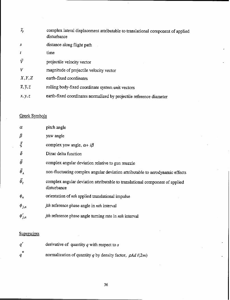
S
t
v V
x,y,z %jG
& y,z
Greek Svmbols
complex lateral displacement attributable to translational component of applied
disturbance
distance along flight path
time
projectile velocity vector
magnitude of projectile velocity vector
earth-fixed coordinates
rolling body-fixed coordinate system unit vectors
earth-fixed coordinates normalized by projectile reference diameter
pitch angle
yaw angle
complex yaw angle, a+ ip
Dirac delta function
complex angular deviation relative to gun muzzle
non-fluctuating complex angular deviation attributable to aerodynamic effects
complex angular deviation attributable to translational component of applied
disturbance
orientation of nth applied translational impulse
jth reference phase angle in nth interval
jth reference phase angle turning rate in nth interval
derivative of quantity q with respect to s
normalization of quantity q by density factor, pAd l(2m)
36

Miscellaneous
complex representation of quantity 4
vector representation of quantity 4
unit vector 4
37

INTENTIONALLY LEFT BLANK
38

NO. OF COPIES
1
1
1
8
ORGANIZATION
ADMINISTRATOR DEFENSE TECHkICAL INFO CENTER All-N DTICOCP 8725 JOHN J KINGMAN RD STE 0944 FT BELVOIR VA 22060-62 18
DIRECTOR US ARMY RESEARCH LABORATORY ATIN AMSRL CS AS REC MGMT 2800 POWDER MILL RD ADELPHJ MD 20783-l 197
DIRECTOR US ARMY RESEARCH LABORATORY Al-TN AMSRL CI LL TECH LIB 2800 POWDER MILL RD ADELPHI MD 207830-l 197
DIRECTOR US ARMY RESEARCH LABORATORY Al-TN AMSRL DD 2800 POWDER MILL RD ADELPHI MD 20783- 1197
PROJECT MANAGER TANKMAIN ARMAMENT SYSTEMS AT-TN SFAE GCSS TMA
R MORRIS C KIMKER E KOPACZ R DARCY D GUZTEWICZ P CARDELL C CORDING R MCDANOLDS
PICATINNY ARSENAL NJ 07806-5000
COMMANDER US ARMY TACOM ARDEC ATTN SFAE GCSS ARMS R KOWALSKI PICATINNY ARSENAL NJ 07806-5000
COMMANDER US ARMY TACOM ARDEC ATTN SFAE GCSS CR
R BILLINGTON PICATINNY ARSENAL NJ 07806-5000
CDR US ARMY TACOM ARDEC AT-TN AMSTAARCCHA RCARR
M LUCIANO A MUSALLI G KOLASA M PALATHINGAL
PICATINNY ARSENAL NJ 07806-5000
39
NO. OF ORGANIZATION COPIES
2
18
COMMANDER US ARMY TACOM ARDEC Al-TN AMSTA AR QAC
D RIGOGLIOSO R ROESER PICATINNY ARSENAL NJ 07806-5000
CDR US ARMY TACOM ARDEC ATTN AMSTAARFSF T
CLIVECCHLA JGRAU B WONG C NG AFARlNA GMALEJKO S CHUNG E VAZQUEZ SHAN HHUDGINS WTOLEDO LYEE D PEDERSEN R TROHANOWSKY A FIORELLINI J THOMASOVICH MAMORUSO JMURNANE
PICATINNY ARSENAL NJ 07806-5000
COMMANDER US ARMY TACOM ARDEC A’ITN AMSTA AR FSF D
K PFLEGER R TESTA E LA ROSA
PICATJNNY ARSENAL NJ 07806-5000
COMMANDER US ARMY TACOM ARDEC AT-TN AMSTA ARCCHB RSAYER
F CHANG G EUSTICE S PATEL G WAGNECZ
PICATINNY ARSENAL NJ 07806-5000
CDR US ARMY TACOM ATT’N SFAE GCSS W COL J MORAN
LTC S COOPER LTC R GROLLER JNEFF JFLECK S GOODMAN J FLORENCE
WARREN MI 48397-5000
DIRECTOR US ARMY ARMOR CIR ATT-N ATZK TD APOMEY FT’KNOX KY 40121
DIRECTOR US ARMY ARMOR CTR Al-TN ATZK TS W MEINSHAUSEN FTKNOX KY 40121

NO. OF COPIES ORGANIZATION
CDR US ARMY MICOM ATIN AMSAM RD PS J COCHRAN
AMSMI RD ST P JACOBS PRUFFIN WWALKER
AMSMI RD ST T VANDIVER D DAVIS
AMSMJ RD MG C LEWIS C ROBERTS
REDSTONE ARSENAL AL 35898-5247
DIRECTOR HQ IOC AT-IN AMSIO SMT W HARRIS
M RIVERS ROCK ISLAND IL 61299-6000
DIRECTOR BENETLABORATORIES Al-TN AMSTAARCCB JVASILAKJS
R HASENBEIN G PFLEGL WATERVLIET NY 12189
AJR FORCE RESEARCH LAB AT-l-N AAC /MN S LEFSTAD
R WEHLING R JONES TGRADY GABATE M DEILER JWISE R ZACHERY G WINCHENBACH
101 W EGLIN BLVD STE 219 EGLINAFB FL 32542
AIR FORCE RESEARCH LAB AT-l-N AAC I W (JASSM)
TLlTTLE JFELICI S BROOKS D BRIDGES R KIRBY T MCCOOL
102 WEST D AVE EGLINAFB FL 32542
NAVAL AIR WARFARE CTR All-N WGUNTHER ONE ADMINISTRATION CIRCLE 473500D CHINALAKE CA 93555-6100
NAT GROUND INTEL CTR AT-IN JMORGAN 220 7TH ST NE CHARLOTTESVILLE VA 22902-5396
NO. OF COPIES ORGANIZATION
INST FOR ADVANCED TECHNOLOGY UN-IV OF TEXAS AT AUSTIN ATTN WREINECKE 4030-2 W BRAKER LANE AUSTIN TX 78759-5329
OREGON STATE UNIVERSITY DEP MECHANICAL ENGINEERING ATIN M COSTELLO CORVALLIS OR 9733 1
US MILITARY ACADEMY DEP MATHEMATICAL SCIENCES ATTNMGRAHAM
WEST POINT NY 10996-1786
UNTV OF CINCINNATI DEP AEROSPACE ENGINEERING
& ENGINEERING MECHANICS ATI’N G SLATER S RUBIN
KGHIA PORKWIS P KHOSLA
CINCINNATI OH 45221
SVERDRUE’ TECHNOLOGY INC ATTN GMOLVIK 1099 AVE C ARNOLD AFB TN 37389-9013
ALLIANT TECHSYSTEMS Al-TN C AAKHUS R BECKER
RDOHRN CCANDLAND J GILES M JANTSCHER
6002NDST NE HOPKINS MN 55343-8367
PRIMEX CORPORATION Al-TN DOSMENT ESTEINER PO BOX 127 RED LION PA 17356
PRIMEX CORPORATION AT-TN LWHITMORE W PERKJNS
T NEAVES 101019TH ST NORTH STPETERSBURG FL 33702
ARROW TECH ASSOCIATES ATT’N RWHYTE WHATHAWAY
AHATHAWAY JWHYTE 1233 SHELBURNE RD SUITE D-8 SOUTH BURLINGTON VT 05403
40
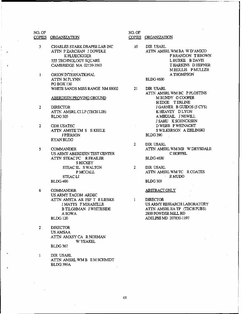
NO. OF NO. OF COPIES ORGANJZATION COPJES ORGANIZATION
CHARLES STARK DRAPER LAB JNC AT-l-N PZARCHAN JDOWDLE
K FLUECIUGER 555 TECHNOLOGY SQUARE CAMBRIDGE MA 02139-3563
ORION JNTkNATIONAL AT-TN MFLYNN PO BOX 130 WHITE SANDS MISS RANGE NM 88002
ABERDEEN PROVING GROUND
DIRECTOR ATJ’N AMSRL CI LP (TECH LIB) BLDG 305
CDR USATEC Al-TN AMSTETM S EKEELE
J PIERSON RYAN BLDG
COMMANDER US ARMY ABERDEEN TEST CENTER AT-TN STEAC FC R FRAILER
s HJCKEY STEAC SL S WALTON
P MCCALL STEAC LI
BLDG 400
COMMANDER US ARMY TACOM ARDEC Al-TN AMSTA AR FSF T RLJESKE
JMATTS FMIRABELLE B TILGHMAN JWHJTESIDE A SOWA
BLDG 120
DIRECTOR us AMSAA ATTN AMXSY CA R NORMAN
WYEAKEL BLDG 367
DIR USARL A-ITN AMSRLWMB EMSCHMIDT BLDG 390A
10
21
DIR USARL ATTN AMSRLWMBA WD’AMJCO
F BRANDON T BROWN L BURKE B DAVIS THARIUNS DHEPNER M HOLLIS P MULLER A THOMPSON
BLDG 4600
DIR USARL AT-l-N AMSRL WM BC P PLOSTJNS
M BUNDY G COOPER HEDGE T ERLINE J GARNER B GUJDOS (5 CYS) K HEAVEY D LYON AMJKHAJL JNEWILL J SAHU K SOENCKSEN DWEBB PWEJNACHT S WILKERSON A ZJELINSKJ
BLDG 390
DIR USARL Al-TN AMSRL WM MB W DRYSDALE
C HOPPEL BLDG 4600
DIR USARL AT-TN AMSRLWMTC RCOATES
RMUDD BLDG 309
ABSTRACT ONLY
DIRECTOR US ARMY RESEARCH LABORATORY AT-TN AMSRL EA TP (TECH PUBS) 2800 POWDER MILL RD ADELPHI MD 207830-l 197
41

INTENTIONALLY LEFT BLANK
42

REPORT DOCUMENTATION PAGE Form Approved OMB No. 0704-0188
Public reporting burden for this collection of information is estimated to average 1 hour par resports~, including the time for revieying instructions, searching existing data sources, gathering and maintaining the data needed, and completing and reviewing the collection of informatIon. Send comments r ardmg this burden es&mate or any other aspect of this collection of information, m&ding suggesbons for reducing this burden, to Washington Headquartets Services, Directorate or Information Operations and Reports, 1215 Jefferson “9 Davis Highway, Suite 1204, Arlington, VA 22202-4302, and to the Office of Management and Budget, Papenvork Reduction Project (0704-0188), Washington, DC 20503.
1. AGENCY USE ONLY (Leave blank) 2. REPORT DATE 3. REPORT TYPE AND DATES COVERED
December 1999 Final
4. TITLE AND SUBTITLE 5. FUNDING NUMBERS
The Effect of a Simple Lateral Impulse on Kinetic Energy Projectiles in Flight Project No. lL1622618.AH80
6. AUTHOR(S)
Guidos, B.J.; Cooper, G.R. (both of ARL)
7. PERFORMING ORGANIZATION NAME(S) AND ADDRESS 8. PERFORMING ORGANIZATION REPORT NUMBER
U.S. Army Research Laboratory
Weapons & Materials Research Directorate Aberdeen Proving Ground, MD 21010-5066
3. SPONSORING/MONITORING AGENCY NAME(S) AND ADDRESS 10. SPONSORING/MONITORING
U.S. Army Research Laboratory AGENCY REPORT NUMBER
Weapons & Materials Research Directorate ARL-TR-2076 Aberdeen Proving Ground, MD 2 10 lo-5066
Il. SUPPLEMENTARY NOTES
12a. DISTRIBUTION/AVAILABILITY STATEMENT 12b. DISTRIBUTION CODE
Approved for public release; distribution is unlimited.
13. ABSTRACT (Maximum 200 words)
Existing analytical theory for quantifying the free-flight motion of non-rolling, statically stable projectiles is extended to include the
effect of a simple lateral impulse applied during flight. The extended theory is based on the incorporation of generalized lateral translational and angular disturbances into the familiar equations of projectile free-flight motion. The applied disturbances are then modeled using specified mathematical forms, and the modified equations are solved to obtain the angular and translational motion of the projectile over the trajectory. The various components of the translational motion of the projectile are extracted and
characterized. An idealized application is presented for a large caliber finned projectile, representative of the class of 120-mm long rod kinetic energy projectiles fired from the Ml Al Abrams tank, subjected to a single lateral control impulse in flight. The
analytical closed form solutions are validated against results obtained using a numerical trajectory simulation code that incorporates generalized guidance and control commands.
4. SUBJECT TERMS 15. NUMBER OF PAGES
course correction guidance and control lateral jet 50
flight dynamics kinetic energy projectile projectile dynamics 16. PRICE CODE
7. SECURITY CLASSIFICATION 18. SECURtTY CLASSIFICATION 19. SECURITY CLASSIFICATION 20. LIMITATION OF ABSTRACT
OF REPORT OF THIS PAGE OF ABSTRACT
Unclassified Unclassified Unclassifted
NSN 7540-01-280-5500 43 Standard Form 298 (Rev. 2-89) Prescribed by ANSI Std. 239-18 298-l 02