Embed Size (px)
Citation preview

ILF CONSULTING ENGINEERS
Werner-Eckert-Str. 7, 81829 Munich, GERMANY Phone: +49-89-25 55 94 - 0 Fax: +49-89-25 55 94 - 144 E-mail: [email protected]
K358-ILF-OVA-GEN-IN-SPC-0011/REV.1
Project Management & FEED Consultancy Services
SPECIFICATION FOR SECURITY SYSTEMS
05/10/2017
TAPI Pipeline Company Limited
Project Management & FEED Consul tancy Services K358-ILF-OVA-GEN-IN-SPC-0011/Rev.1 Spec i f icat ion for Secur i t y Systems 05/10/2017
I L F C O N S U L T I N G E N G I N E E R S P a g e 2 of 59
ILF-GER K358-ILF-OVA-GEN-IN-SPC-0011_1_Specification for Security Systems.docx © ILF 2017
REVISION
1 05.10.2017 APV-Approved by Company Phase I & II
Pimentel Kosikova Pfnuer
0 30.08.2017 IFR – Issued for Review Haselhoff Kosikova Pfnuer
Rev. Date Issue, Modification Prepared Checked Approved

Project Management & FEED Consul tancy Services K358-ILF-OVA-GEN-IN-SPC-0011/Rev.1 Spec i f icat ion for Secur i t y Systems 05/10/2017
I L F C O N S U L T I N G E N G I N E E R S P a g e 3 of 59
ILF-GER K358-ILF-OVA-GEN-IN-SPC-0011_1_Specification for Security Systems.docx © ILF 2017
TABLE OF CONTENTS
1 INTRODUCTION 6
1.1 Project 6
1.2 Project Phases 7
1.3 Purpose of the Document 7
1.4 Definitions 9
1.5 Abbreviations 9
1.6 Referenced Documents 12
2 CODES AND STANDARDS 14
3 ORDER OF PRECEDENCE 17
4 ENVIRONMENTAL CONDITIONS 18
5 BASIC REQUIREMENTS 19
5.1 Project Phases and the Telecommunications System 19
5.2 General 19
5.3 Integrated Security System 21
5.4 CCTV System 22
5.5 Perimeter Intrusion Detection System 24
5.6 Access Control System (Persons and Vehicles) 25
5.7 Security Network 27
5.8 Detailed Security Operation Concept Study 29
5.9 Availability 29
5.10 Cyber Security 30
5.11 Power Supply 30
5.12 Field Proven 30
5.13 Hazardous Areas 30
5.14 Maintainability 30
5.15 System Diagnostic 32
5.16 Adaptivity and Maintenance 33
5.17 Expandability 33
Project Management & FEED Consul tancy Services K358-ILF-OVA-GEN-IN-SPC-0011/Rev.1 Spec i f icat ion for Secur i t y Systems 05/10/2017
I L F C O N S U L T I N G E N G I N E E R S P a g e 4 of 59
ILF-GER K358-ILF-OVA-GEN-IN-SPC-0011_1_Specification for Security Systems.docx © ILF 2017
5.18 Operating System 33
5.19 Reduced Complexity 34
5.20 Licences 34
5.21 Time Synchronization - Daylight Saving Time switching 34
5.22 Disaster Recovery 34
5.23 Redundancy 34
6 EQUIPMENT HOUSING 35
6.1 General 35
6.2 Computer / Server Cabinets 35
6.3 Switch Cabinets 36
6.4 Outdoor Equipment Boxes 37
7 HARDWARE 37
7.1 Cabling 37
7.2 Servers 37
7.3 Workplaces 38
7.3.1 General 38
7.3.2 Operator Workstation 39
7.4 Video Wall 39
7.5 Data Storage 40
7.6 Network Attached Storage 40
7.7 Long Term Archive 41
7.8 Fence Intrusion Detection System (FIDS) 41
7.9 Microwave Electronic Intrusion Detector 42
7.10 Buried Outdoor Perimeter Intrusion Detection System (BIDS) 43
7.11 RFID Card Reader (long and short range) 44
7.12 RFID Card Reader with Screen 44
7.13 Combined RFID Card and Fingerprint Reader 44
7.14 Combined RFID Card and Fingerprint Management Kit 45
7.15 Electric Door Opener 45
7.16 Door Contacts 45
7.17 Pan Tilt Zoom (PTZ) Day/Night Cameras 45
Project Management & FEED Consul tancy Services K358-ILF-OVA-GEN-IN-SPC-0011/Rev.1 Spec i f icat ion for Secur i t y Systems 05/10/2017
I L F C O N S U L T I N G E N G I N E E R S P a g e 5 of 59
ILF-GER K358-ILF-OVA-GEN-IN-SPC-0011_1_Specification for Security Systems.docx © ILF 2017
7.18 Combined Pan Tilt Zoom Thermal Camera Day/Night Camera System 46
7.19 Fixed camera Days/Night outdoor 47
7.20 Pan Tilt Zoom PTZ cameras indoor 48
7.21 Poles for Cameras 48
7.22 Turnstiles 49
7.23 Vehicle barriers 49
8 OPERATIONAL REQUIREMENTS 50
8.1 General 50
8.2 Security and Privilege Levels of Users 50
8.2.1 Area restricted level 50
8.2.2 Login and Logout 50
9 QUALITY ASSURANCE, INSPECTION AND TESTING 51
9.1 Quality Assurance 51
9.2 Factory Inspection and Testing 51
9.2.1 General 51
9.2.2 Factory Acceptance Test (FAT) 51
9.2.3 Integrated Factory Acceptance Test (IFAT) 52
9.3 Site Acceptance Test (SAT) 52
9.4 Performance Acceptance Test (PAT) 53
9.5 Nameplate Details 53
10 PACKAGING, PRESERVATION AND PREPARATION FOR SHIPMENT 54
11 SPARE PARTS AND SPECIAL TOOLS SPARES 55
12 TRAINING 55
13 DOCUMENTATION 56
13.1 General 56
13.2 Documentation to be submitted with the Bid 56
13.3 Documentation to be submitted after receiving the Purchase Order / As Built 57
13.4 Final Documentation 59

Project Management & FEED Consul tancy Services K358-ILF-OVA-GEN-IN-SPC-0011/Rev.1 Spec i f icat ion for Secur i t y Systems 05/10/2017
I L F C O N S U L T I N G E N G I N E E R S P a g e 6 of 59
ILF-GER K358-ILF-OVA-GEN-IN-SPC-0011_1_Specification for Security Systems.docx © ILF 2017
1 INTRODUCTION
1.1 Project
The TAPI Project was originally conceived in the 1990s with a view to monetise Turk-
menistan’s vast natural gas reserves through gas exports to Afghanistan, Pakistan and
India.
In 2013, the Governments of Turkmenistan, Afghanistan, Pakistan and India respectively
nominated state-owned gas companies State Concern “Turkmengas”, Afghan Gas En-
terprise, Inter State Gas Systems (Private) Limited, and GAIL (India) Limited to promote
and invest in the TAPI Project.
The TAPI Project aims to export up to 33 billion cubic meters of natural gas annually for
30 year period through a 1814 km pipeline from Turkmenistan to Afghanistan, Pakistan
and India.
In November 2014, with the collaboration of the four abovementioned state-owned gas
companies, TPCL was incorporated with the main objective of implementing the TAPI
Project.
TPCL is a company limited by shares and incorporated in Isle of Man with a registered
office at the following address: Fort Anne, Douglas, Isle of Man, IM1 5PD. The head of-
fice of TPCL is located in Dubai, United Arab Emirates.
In June 2015, State Concern “Turkmengas” was unanimously elected as a Consortium
Leader for the TAPI Project.
The stone-laying ceremony for the TAPI Project was held in the Mary region of Turkmen-
istan, near the Galkynysh natural gas field, on 13 December 2015 and was attended by
Gurbanguly Berdimuhamedov, the President of Turkmenistan, Nawaz Sharif, the Prime
Minister of Pakistan, Ashraf Ghani Ahmadzai, the President of Afghanistan and Moham-
mad Hamid Ansari, the Vice-President of India.
The Shareholders’ Agreement was signed concurrently with the TAPI Project stone-
laying ceremony. In April 2016, the Shareholders of TPCL signed the Investment Agree-
ment.
In January 2017, TPCL entered into a Project Management and FEED Development
Contract in connection with the Afghanistan and Pakistan section of TAPI Project with
ILF Beratende Ingenieure GmbH.
The implementation of the TAPI Project is divided into three main phases:
a) Natural gas source development;

Project Management & FEED Consul tancy Services K358-ILF-OVA-GEN-IN-SPC-0011/Rev.1 Spec i f icat ion for Secur i t y Systems 05/10/2017
I L F C O N S U L T I N G E N G I N E E R S P a g e 7 of 59
ILF-GER K358-ILF-OVA-GEN-IN-SPC-0011_1_Specification for Security Systems.docx © ILF 2017
b) Turkmenistan portion of the TAPI Project; and
c) Afghanistan and Pakistan portion of the TAPI Project.
TPCL will act as the employer in relation to the construction works, as well as the owner
of the Afghanistan and Pakistan portion of the TAPI Project.
The “Galkynysh” gas field, which is listed among the world’s largest natural gas fields
and holds 26.2 trillion cubic meters of gas reserves, will be the source of natural gas for
the TAPI Project.
Phase III of the development of the Galkynysh gas field has been initiated by State Con-
cern “Turkmengas” so as to meet its obligations to supply natural gas to the TAPI Pro-
ject.
The length of the Turkmenistan portion of the TAPI Project is 214 km. State Concern
“Turkmengas” has already started the engineering and initial phase of the construction
works on this portion of the TAPI Project.
The length of Afghanistan and Pakistan portion of the TAPI Project is 1600 km.
1.2 Project Phases
Aforementioned Project (Afghanistan and Pakistan portion of the TAPI Project) has been
split into two phases, namely Phase I and Phase II.
Phase I aims to pressurize gas at the last compressor station located in Turkmenistan
and to deliver gas free flow (reduced flow) to Afghanistan, Pakistan and India without any
additional gas compression in Afghanistan and Pakistan. Block valve stations, scraper
facilities, metering and offtake stations along the pipeline are within the scope of Phase I.
Phase II aims to finalize the full scale project (incl. Compressor Stations) to fulfil the full
flow gas delivery contract.
It shall be noted, that the document has been structured in a way to cover both Phases
of the Project.
1.3 Purpose of the Document
The requirements set forth within this document, and related documents, define the min-
imum requirements acceptable to the for design, delivery, installation, testing and tuning
of the Security Systems. Security Systems hardware and software shall be supplied fully
in accordance with this specification.
The Company assumes that the Contractor has comprehensive experience in Security
Systems in the hydro carbon transport industries. It is the responsibility of the Contractor

Projec t Management & FEED Consul tancy Services K358-ILF-OVA-GEN-IN-SPC-0011/Rev.1 Spec i f icat ion for Secur i t y Systems 05/10/2017
I L F C O N S U L T I N G E N G I N E E R S P a g e 8 of 59
ILF-GER K358-ILF-OVA-GEN-IN-SPC-0011_1_Specification for Security Systems.docx © ILF 2017
to ensure that they obtain, review and fully understand all implications on the scope of
work resulting from this specification.
The completeness of bid documentation and the stated ability of renderers to meet the
requirements set out below will be an initial part of the Bid evaluation. The documents
which are required for the Bid evaluation of the Security systems are listed within this
document. Furthermore this specification shall lay the basis to establish clear unambigu-
ous testing and performance criteria for FAT and SAT.

Project Management & FEED Consul tancy Services K358-ILF-OVA-GEN-IN-SPC-0011/Rev.1 Spec i f icat ion for Secur i t y Systems 05/10/2017
I L F C O N S U L T I N G E N G I N E E R S P a g e 9 of 59
ILF-GER K358-ILF-OVA-GEN-IN-SPC-0011_1_Specification for Security Systems.docx © ILF 2017
1.4 Definitions
Company : TAPI Pipeline Company Limited
Consultant : ILF Beratende Ingenieure GmbH
Contractor : Companies under contract with the Company
for the performance of works/services for the
Overall Project
Overall Project : Turkmenistan – Afghanistan – Pakistan –
India (TAPI) Gas Pipeline Project
Project : Project Management and FEED Consultancy
Services for the Afghanistan and Pakistan
portions of the TAPI Pipeline Project
Subconsultants : Companies under contract with the Consult-
ant for the execution of the Project
SubCONTRACTOR : Companies under contract with the Contrac-
tor for the execution of works/services for the
Overall Project
1.5 Abbreviations
Locations:
AFG : Afghanistan
BS : Block Valve Station
CS : Compressor Station
PAK : Pakistan
IND : India
MS : Metering Station
OS : Offtake Station
TAPI : Turkmenistan – Afghanistan – Pakistan – India
TKM : Turkmenistan
Project Management & FEED Consul tancy Services K358-ILF-OVA-GEN-IN-SPC-0011/Rev.1 Spec i f icat ion for Secur i t y Systems 05/10/2017
I L F C O N S U L T I N G E N G I N E E R S P a g e 10 of 59
ILF-GER K358-ILF-OVA-GEN-IN-SPC-0011_1_Specification for Security Systems.docx © ILF 2017
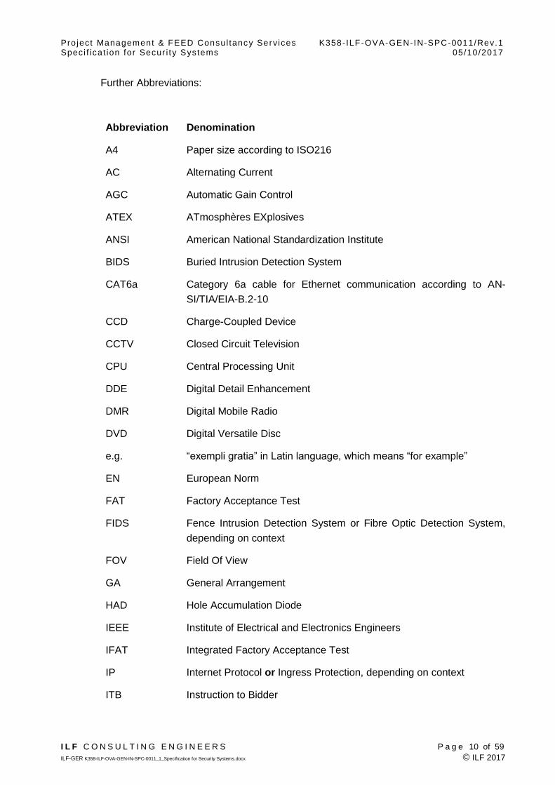
Further Abbreviations:
Abbreviation Denomination
A4 Paper size according to ISO216
AC Alternating Current
AGC Automatic Gain Control
ATEX ATmosphères EXplosives
ANSI American National Standardization Institute
BIDS Buried Intrusion Detection System
CAT6a Category 6a cable for Ethernet communication according to AN-
SI/TIA/EIA-B.2-10
CCD Charge-Coupled Device
CCTV Closed Circuit Television
CPU Central Processing Unit
DDE Digital Detail Enhancement
DMR Digital Mobile Radio
DVD Digital Versatile Disc
e.g. “exempli gratia” in Latin language, which means “for example”
EN European Norm
FAT Factory Acceptance Test
FIDS Fence Intrusion Detection System or Fibre Optic Detection System,
depending on context
FOV Field Of View
GA General Arrangement
HAD Hole Accumulation Diode
IEEE Institute of Electrical and Electronics Engineers
IFAT Integrated Factory Acceptance Test
IP Internet Protocol or Ingress Protection, depending on context
ITB Instruction to Bidder
Project Management & FEED Consul tancy Services K358-ILF-OVA-GEN-IN-SPC-0011/Rev.1 Spec i f icat ion for Secur i t y Systems 05/10/2017
I L F C O N S U L T I N G E N G I N E E R S P a g e 11 of 59
ILF-GER K358-ILF-OVA-GEN-IN-SPC-0011_1_Specification for Security Systems.docx © ILF 2017
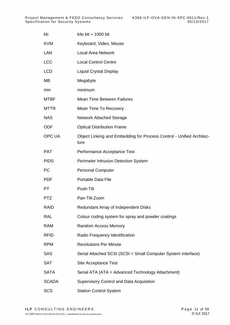
kb kilo bit = 1000 bit
KVM Keyboard, Video, Mouse
LAN Local Area Network
LCC Local Control Centre
LCD Liquid Crystal Display
MB Megabyte
min minimum
MTBF Mean Time Between Failures
MTTR Mean Time To Recovery
NAS Network Attached Storage
ODF Optical Distribution Frame
OPC UA Object Linking and Embedding for Process Control - Unified Architec-
ture
PAT Performance Acceptance Test
PIDS Perimeter Intrusion Detection System
PC Personal Computer
PDF Portable Data File
PT Push-Tilt
PTZ Pan-Tilt-Zoom
RAID Redundant Array of Independent Disks
RAL Colour coding system for spray and powder coatings
RAM Random Access Memory
RFID Radio Frequency Identification
RPM Revolutions Per Minute
SAS Serial Attached SCSI (SCSI = Small Computer System Interface)
SAT Site Acceptance Test
SATA Serial ATA (ATA = Advanced Technology Attachment)
SCADA Supervisory Control and Data Acquisition
SCS Station Control System
Project Management & FEED Consul tancy Services K358-ILF-OVA-GEN-IN-SPC-0011/Rev.1 Spec i f icat ion for Secur i t y Systems 05/10/2017
I L F C O N S U L T I N G E N G I N E E R S P a g e 12 of 59
ILF-GER K358-ILF-OVA-GEN-IN-SPC-0011_1_Specification for Security Systems.docx © ILF 2017
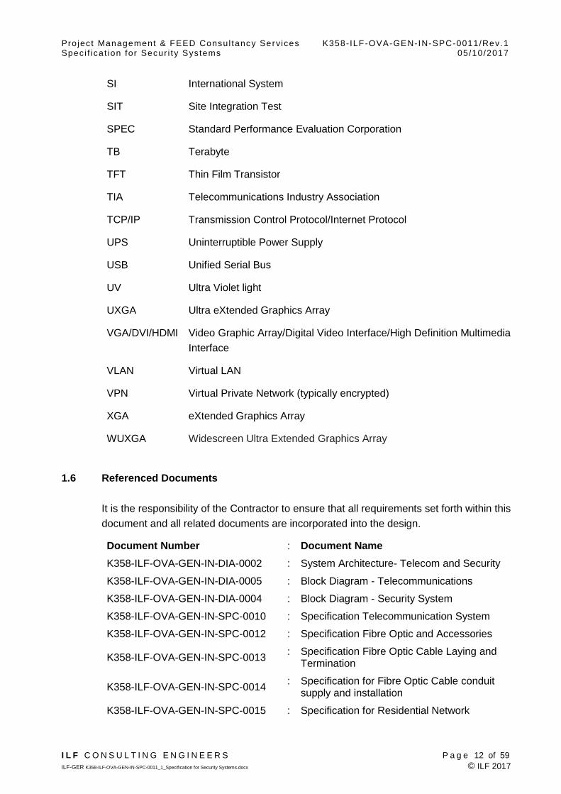
SI International System
SIT Site Integration Test
SPEC Standard Performance Evaluation Corporation
TB Terabyte
TFT Thin Film Transistor
TIA Telecommunications Industry Association
TCP/IP Transmission Control Protocol/Internet Protocol
UPS Uninterruptible Power Supply
USB Unified Serial Bus
UV Ultra Violet light
UXGA Ultra eXtended Graphics Array
VGA/DVI/HDMI Video Graphic Array/Digital Video Interface/High Definition Multimedia
Interface
VLAN Virtual LAN
VPN Virtual Private Network (typically encrypted)
XGA eXtended Graphics Array
WUXGA Widescreen Ultra Extended Graphics Array
1.6 Referenced Documents
It is the responsibility of the Contractor to ensure that all requirements set forth within this
document and all related documents are incorporated into the design.
Document Number : Document Name
K358-ILF-OVA-GEN-IN-DIA-0002 : System Architecture- Telecom and Security
K358-ILF-OVA-GEN-IN-DIA-0005 : Block Diagram - Telecommunications
K358-ILF-OVA-GEN-IN-DIA-0004 : Block Diagram - Security System
K358-ILF-OVA-GEN-IN-SPC-0010 : Specification Telecommunication System
K358-ILF-OVA-GEN-IN-SPC-0012 : Specification Fibre Optic and Accessories
K358-ILF-OVA-GEN-IN-SPC-0013 : Specification Fibre Optic Cable Laying and
Termination
K358-ILF-OVA-GEN-IN-SPC-0014 : Specification for Fibre Optic Cable conduit
supply and installation
K358-ILF-OVA-GEN-IN-SPC-0015 : Specification for Residential Network

Project Management & FEED Consul tancy Services K358-ILF-OVA-GEN-IN-SPC-0011/Rev.1 Spec i f icat ion for Secur i t y Systems 05/10/2017
I L F C O N S U L T I N G E N G I N E E R S P a g e 13 of 59
ILF-GER K358-ILF-OVA-GEN-IN-SPC-0011_1_Specification for Security Systems.docx © ILF 2017
Document Number : Document Name
K358-ILF-OVA-GEN-IN-DIA-0001- : System Architecture - Overall Pipeline
Control
K358-ILF-OVA-GEN-IN-DIA-0016 : Block Diagrams - Residential Network
K358-ILF-OVA-GEN-EL-SPC-0016 Specification Electrical and ICT Equipment
Containers
K358-ILF-OVA-GEN-PR-REP-0010 : -TAG Numbering Procedure
K358-ILF-OVA-GEN-GE-REP-0001 : Basis of Design
Project Management & FEED Consul tancy Services K358-ILF-OVA-GEN-IN-SPC-0011/Rev.1 Spec i f icat ion for Secur i t y Systems 05/10/2017
I L F C O N S U L T I N G E N G I N E E R S P a g e 14 of 59
ILF-GER K358-ILF-OVA-GEN-IN-SPC-0011_1_Specification for Security Systems.docx © ILF 2017
2 CODES AND STANDARDS
All work must meet or exceed applicable requirements set forth by the latest edition of
the following international and national codes and standards.
International Regulations:
IEC International Electrotechnical Commission
EN European Norms
ETSI European Standards Organisation
ISO International Organization for Standardization
ISA The International Society of Automation
SI International Systems of Units
EU European Union
ITU International Telecommunication Union
Specifically
EN 50130-4 Electromagnetic compatibility; Product family stand-
ard: Immunity requirements for components of fire, in-
truder and social alarm systems
EN 50131 Intrusion and hold-up systems
EN 62676 Video surveillance systems for use in security applica-
tions
EN 60839 Alarm and electronic security systems
EN 50136 Alarm transmission systems and equipment
ISO 11801 Generic cabling for customer premises
ISO/IEC 12207 Software testing, integration and documentation
EN IEC 60617 Graphical Symbols for Diagrams; all the Parts
IEC 60079 Series Explosive Atmospheres Standards
IEC/TR 62541 OPC Unified Architecture – all parts
ISO 14617( Part 1-7) Graphical symbols for diagrams
IEC 61508 Functional Safety of Electrical/ Electronic/ Program-
mable Electronic Safety-related Systems

Project Management & FEED Consul tancy Services K358-ILF-OVA-GEN-IN-SPC-0011/Rev.1 Spec i f icat ion for Secur i t y Systems 05/10/2017
I L F C O N S U L T I N G E N G I N E E R S P a g e 15 of 59
ILF-GER K358-ILF-OVA-GEN-IN-SPC-0011_1_Specification for Security Systems.docx © ILF 2017
EU Directives ATEX 95 (94/9/EC) Use of Equipment in potentially explosive at-
mosphere
IEC 60079 Series Explosive Atmospheres Standards
ANSI/IEC 60529 Degrees of Protection Provided by Enclosures (IP
Code)
IEC 60950-1 Information technology equipment. Safety; Part 1-
General requirements; Safety aspects (specific
Clauses)
ISO 10026 Open Systems Interconnection (or ISO/IEC 10026)
ISO 9241 Ergonomics of human-system interaction
ISO 11064 Ergonomic Design of Control Centres (all the parts)
IEC 62381 Ed.2 Automation systems in the process industry - Factory
acceptance test (FAT), site acceptance test (SAT),
and site integration test (SIT)
IEC 62337 Ed.2 Commissioning of electrical, instrumentation and con-
trol systems in the process industry - Specific phases
and milestones
DIN EN 62337:2011-01 Commissioning of electrical, instrumentation and con-
trol systems in the process industry - Specific phases
and milestones (IEC 65E/166/CDV:2010);
ISO/IEC 25010 Systems and software engineering. Systems and
software quality requirements and evaluation
(SQuaRE). Systems and software quality models
(2011)
IEC 62541 OPC Unified Architecture
ITU-T Series ITU Telecommunication Sector Standards
National American Standards, Regulation
ANSI American National Standards Institute
AGA American Gas Association
API American Petroleum Institute
IEEE Institute of Electrical and Electronic Engineers
IETF International Engineering Task Force
Project Management & FEED Consul tancy Services K358-ILF-OVA-GEN-IN-SPC-0011/Rev.1 Spec i f icat ion for Secur i t y Systems 05/10/2017
I L F C O N S U L T I N G E N G I N E E R S P a g e 16 of 59
ILF-GER K358-ILF-OVA-GEN-IN-SPC-0011_1_Specification for Security Systems.docx © ILF 2017
Specifically
IEEE 802 series Standards for Local and Metropolitan Networks
API 1164 Pipeline SCADA security, 2009
ISO27001 Information technology — Security techniques — Information
security management systems — Overview and vocabulary
National British Standards, Regulation
BS British Standards Institute
Specifically
BS OHSAS 18001 Occupational Health and Safety

Project Management & FEED Consul tancy Services K358-ILF-OVA-GEN-IN-SPC-0011/Rev.1 Spec i f icat ion for Secur i t y Systems 05/10/2017
I L F C O N S U L T I N G E N G I N E E R S P a g e 17 of 59
ILF-GER K358-ILF-OVA-GEN-IN-SPC-0011_1_Specification for Security Systems.docx © ILF 2017
3 ORDER OF PRECEDENCE
The precedence for application of Codes, Standards, Design Practices, tender docu-
ments and Regulatory requirements for the project shall be as follows:
Contract Documents;
International Codes and Standards;
Local Government Acts and Regulations;
Project Documents; and
Good engineering practice.
When there are conflicts between the above documents, the most conservative and/or
safest requirements applicable to the project will prevail. Any decision related to an in-
consistency, conflict or discrepancy is subject to approval by the Company. Any incon-
sistencies critical to the design shall be brought to the attention of the Company for reso-
lution and Company’s interpretation shall be final.

Project Management & FEED Consul tancy Services K358-ILF-OVA-GEN-IN-SPC-0011/Rev.1 Spec i f icat ion for Secur i t y Systems 05/10/2017
I L F C O N S U L T I N G E N G I N E E R S P a g e 18 of 59
ILF-GER K358-ILF-OVA-GEN-IN-SPC-0011_1_Specification for Security Systems.docx © ILF 2017
4 ENVIRONMENTAL CONDITIONS
All supplied hardware equipment shall be suitable for continuous operation in the indoor
ambient conditions as defined below. The equipment shall be also suitable for shipment
and storage in outdoor ambient conditions as defined in the document K358-ILF-OVA-
GEN-GE-REP-0001 Basis of Design, Chapter 2.5 ‘Meteorological Data within Project Ar-
ea’.
In all compressor stations metering and offtake stations the hardware equipment in-
stalled in A/C acclimatized rooms shall be suitable for the following controlled ambient
conditions:
Minimum temperature: +5°C;
Maximum temperature: +35°C; and
Humidity: <80%.
Those parts of the equipment installed inside of non climatized rooms shall be suitable
for the following ambient conditions:
Minimum temperature: 0°C;
Maximum temperature: +60°C; and
Humidity: <95%.
Those parts of the equipment installed outside of buildings in outdoor cabinets/boxes
shall be suitable for the following ambient conditions:
Minimum temperature: -10°C;
Maximum temperature: +75°C; and
Humidity: <95%.
In all block valve stations the hardware equipment will be installed in cabinets inside the
dedicated equipment container with the following ambient conditions , according to K358-
ILF-OVA-GEN-EL-SPC-0016-Specification Electrical and ICT Equipment Containers:
Minimum temperature: +5°C;
Maximum temperature: +45°C; and
Humidity: <95%.
Project Management & FEED Consul tancy Services K358-ILF-OVA-GEN-IN-SPC-0011/Rev.1 Spec i f icat ion for Secur i t y Systems 05/10/2017
I L F C O N S U L T I N G E N G I N E E R S P a g e 19 of 59
ILF-GER K358-ILF-OVA-GEN-IN-SPC-0011_1_Specification for Security Systems.docx © ILF 2017
5 BASIC REQUIREMENTS
5.1 Project Phases and the Telecommunications System
The TAPI pipeline system is designed in the Phase I for free flow and in the Phase II for
operation with compressor stations.
Design shall be provided by Contractor in the Phase I, so that for the implementation of
Phase II only extension of existing equipment is necessary. Replacement of equipment
or facilities to implement Phase II shall be avoided. Spare capacity, spare place, etc.
shall be considered in the Phase I by Contractor.
In Phase I the LCCs will be located in AFG-MS01, in Afghanistan, and PAK-MS01 in Pa-
kistan.
In the Phase II the LCCs with related equipment shall be relocated from the AFG-MS01
to the AFG-CS01 in Afghanistan, and from PAK-MS01 to PAK-CS1. Design shall be pro-
vided by Contractor in the Phase I accordingly, so that relocation is possible without re-
placement of exiting equipment and facilities.
The “K358-ILF-OVA-GEN-IN-DIA-0002 System Architecture- Telecom and Security”,
“K358-ILF-OVA-GEN-IN-DIA-0005 Block Diagram – Telecommunications”, and “K358-
ILF-OVA-GEN-IN-DIA-0004 Block Diagram - Security System” indicate the requirements
for each one of the Phases, at each location of the pipeline system.
5.2 General
The security systems for this project consist mainly of the following sub-systems:
a) Integrated Security System
The integrated security system integrates and interconnects all other security sub-
systems and provides graphical alarm and incident management to the security
staff located at the security buildings of the LCC’s, compressor stations and meter-
ing stations. It supports as well management of access rights.
b) CCTV System
A security Closed Circuit Television System shall be provided to allow the video
surveillance of the project sites, including Compressor stations, Metering stations,
Offtake stations and Block valve stations.
Cameras shall be installed on steel work or individual poles, be of Fixed type, with
Video Motion Detection at the source, or of combined PTZ , thermal type day/night
or PTZ Day/Night Dome as applicable, and be Ex-proof where applicable. Infrared

Project Management & FEED Consul tancy Services K358-ILF-OVA-GEN-IN-SPC-0011/Rev.1 Spec i f icat ion for Secur i t y Systems 05/10/2017
I L F C O N S U L T I N G E N G I N E E R S P a g e 20 of 59
ILF-GER K358-ILF-OVA-GEN-IN-SPC-0011_1_Specification for Security Systems.docx © ILF 2017
illumination (IR) may be used where required. Signal cabling shall be by fibre op-
tics.
The main CCTV systems shall be located in LCCs, CSs and MSs including video
recording facilities. Automatic displaying and video recording shall be triggered by
motion detection and/or PIDS and/or ACS pointing and focusing the respective
section. The system shall generate live images of perimeter fences, gates, premis-
es and access to sensitive areas to be displayed at the main CCTV systems in
LCCs, CSs and MSs.
Camera control panels shall be provided at LCCs, CSs and MSs.
c) Perimeter Intrusion Detection System
A perimeter intrusion detection system shall be provided to detect any attempts to
breach the perimeter at all stations (compressor, metering, offtake, block valve).
In the compressor stations the fence intrusion detection system (FIDS) shall be
based on fibre optic sensor cables interwoven with the perimeter fences of the
second line of defence and microwave transmitters and receivers at perimeter
gates. The sensor cable (sensitive for vibration, flexing, compression and cutting) is
continuously monitored by an analyser unit for cutting or climbing the fences to re-
port any attempted intrusion. The signal is continuously monitored by an analyser
unit for passing of objects to report any trespassing.
In the compressor, metering, offtake, block valve stations a Perimeter Intrusion De-
tection System (BIDS) based on buried outdoor perimeter intrusion detection sen-
sors creating an invisible electromagnetic detection field shall also applied.
In the Compressor stations these systems shall be applied in the area between the
fences of the first and second lines of defence in all other stations around security
wall around the BS/MS and OS stations.
d) Access Control System
An access control system shall be provided to control and monitor the access to
the stations.
Access control servers located at LCCs, CSs and MSs shall synchronize each oth-
er and hold the user IDs and accompanying zone authorizations.
Workstations with camera and badge printer to create access / ID badges shall be
provided in the buildings at LCCs, CSs and MSs.
Remote access controllers comprising proximity type (ex-proof) badge readers and
door release circuitry shall be sited at selected doors / gates of all the stations and
shall be linked to the access control servers. These doors/gates shall be fitted with
emergency access buttons (break glass); its use shall release door locks and raise
an audible and acoustic alarm at the Operator Station. Door locks shall automati-
cally release to open in case of fire or power loss.
Project Management & FEED Consul tancy Services K358-ILF-OVA-GEN-IN-SPC-0011/Rev.1 Spec i f icat ion for Secur i t y Systems 05/10/2017
I L F C O N S U L T I N G E N G I N E E R S P a g e 21 of 59
ILF-GER K358-ILF-OVA-GEN-IN-SPC-0011_1_Specification for Security Systems.docx © ILF 2017
All controlled and un-controlled doors at the stations shall be fitted with (magnetic)
door contacts connected to the remote access controllers.
The remote access controllers for controlled gates at the stations shall provide in-
terfaces to control vehicle barriers and turnstiles.
All controlled gates / doors shall be provided with intercoms.
e) Security Network
Where possible the components of the security systems shall communicate via
Ethernet based services over the Security Network provided by the Telecommuni-
cation system as specified in documents K358-ILF-OVA-GEN-IN-SPC-0010 Speci-
fication for Telecommunication Systems and drawing K358-ILF-OVA-GEN-IN-DIA-
0004-Block Diagrams - Security System.
The Contractor shall provide a complete security system including all equipment, cabling,
patch panels, accessories and works, even if not mentioned explicitly in this document.
The Contractor shall clarify necessity of and arrange for any authority’s licenses, fre-
quency allocations or authority approvals necessary for the specified security system.
The Contractor is responsible to verify that the security system does not interfere with lo-
cal law. Any deviations from this specification shall be clearly identified and submitted for
approval to Company.
The actual number, location and position of cameras shall be provided as per the result
of a study to be prepared by the Contractor in the details design phase (for approval by
Company).
The security system will be completed by communication facilities as specified in docu-
ment K358-ILF-OVA-GEN-IN-SPC-0010 Specification for Telecommunication Systems.
5.3 Integrated Security System
A complete and independent IP/Ethernet based integrated security system shall be pro-
vided at CSs and MS integrating all subsequently described security systems for the in-
dividual station and the associated offtake stations and block valve stations. In addition
remote monitoring of security status and access to videos and archives of all other sta-
tions shall be possible at the LCC’s.
The integrated security system is composed on redundant servers with interfaces to all
other security systems, multiple security operator workstations in security and control
buildings and a large wall screen in each compressor station’s and metering station’s
main security building CCTV equipment room.
The integrated security system shall provide/integrate the user interface for all other sys-
tems including, but not limited to the CCTV system, provide configurable automatic se-
quences (e.g. for camera movements, locking of doors, guidance to operator), provide
Project Management & FEED Consul tancy Services K358-ILF-OVA-GEN-IN-SPC-0011/Rev.1 Spec i f icat ion for Secur i t y Systems 05/10/2017
I L F C O N S U L T I N G E N G I N E E R S P a g e 22 of 59
ILF-GER K358-ILF-OVA-GEN-IN-SPC-0011_1_Specification for Security Systems.docx © ILF 2017
alarm and operator action logging as well as graphical alarm analysis based on automat-
ically shown station and/or building layouts and video streams on the security system
operator workstations and/or the large wall screen.
Further minimum functional requirements for the integrated security system software are:
A customizable graphical user interface, where rights are assigned according to
roles and profiles;
A graphical representation of the station (and its surroundings) / building / floor /
room;
Automatic focus on sections with alarms;
Prioritization of alarms and events;
Permanent monitoring of all sensors and a graphical representation of each sen-
sor’s status;
Providing automatically location- and situation specific response plans;
Integration with all subsystems of the security system;
Automated start of predefined procedures / response plans / CCTV alarm verifi-
cation;
Tamper proof archiving of alarms, events and actions taken by the opera-
tor/security staff;
Security staff schedules and work plans;
Remote operation of electrical door openers, vehicle barriers, turnstiles etc.; and
Generating of Blu-ray disc and DVD compilations at the security workstations to
document events including all sensor reactions, selected video sequences and
subsequent operator action for long term documentation and further analysis
(with special user rights only). These discs shall always contain viewer software,
which does not need installation. Playing of the compilations at the viewer only
with compilation specific password.
5.4 CCTV System
A Security Closed Circuit Television System shall be provided to allow the video surveil-
lance of the project sites, including Compressor stations, offtake stations, metering sta-
tions and block valve stations.
The system shall generate live images of perimeter fences, gates, premises and access
to sensitive areas to be displayed at LCCs, CSs and MSs.
Project Management & FEED Consul tancy Services K358-ILF-OVA-GEN-IN-SPC-0011/Rev.1 Spec i f icat ion for Secur i t y Systems 05/10/2017
I L F C O N S U L T I N G E N G I N E E R S P a g e 23 of 59
ILF-GER K358-ILF-OVA-GEN-IN-SPC-0011_1_Specification for Security Systems.docx © ILF 2017
The main CCTV systems shall be located in CS and MS stations including video record-
ing facilities. Automatic displaying and video recording shall be triggered by motion de-
tection and/or PIDS and/or ACS pointing and focusing the respective section. CCTV
servers shall be located at LCCs, CSs and MS’s.
Camera control panels shall be provided at LCCs, CSs and MSs.
Cameras shall be installed on steel work or individual poles.
Day/night colour PTZ dome cameras shall be installed at the checkpoints and gates of
the Industrial area, at the Entrance Security Check Building and inside the industrial area
of the compressor and metering stations.
At the perimeter fences of the second line of defence (razor/ barbed wire fence) fixed
type day/night cameras with video motion detection at the source shall be installed. The
cameras along the perimeter shall be positioned such that persons can be detected
when moving between outer fence (1st line of defence) and razor/ barbed wire fence
(2nd line of defence).
At the entrances cameras shall be positioned such that the complete entrance area in-
cluding slowed down route areas and protection wall area and the emergency access /
back up entrance area can be monitored without moving the camera view. Streets be-
tween entrances, industrial area and residential area as well as the helicopter landing
pad shall be monitored permanently. No CCTV monitoring is foreseen inside the residen-
tial areas. Inside the industrial area, cameras shall be positioned such that all entrances
of all buildings, all streets and fences as well as all process equipment and other points
of interest can be monitored.
The CCTV system shall be integrated with the intrusion detection systems such that at
least one camera focuses and repositions automatically to the location of the detected in-
trusion or unauthorized door opening.
Pan/Tilt/Zoom thermal cameras (in combination with day/night camera) shall be installed
along the security blast wall and the protection wall in the watch towers of compressor
and metering stations to monitor and detect persons or cars in the surroundings of the
station (up to 1.5 km distance from outer fence) even during total darkness. In order to
cover the entire area to be monitored these cameras shall move through a series of pre-
set positions. Persons, cars etc. and their movement shall be detected for each preset
position as well as between the same preset positions of the previous cycle. The preset
position cycle shall have a maximum duration of one minute.
Infrared illumination (IR) may be used where required. Signal cabling of the CCTV shall
be by fibre optics.
At BS and Offtake stations one such combined thermal camera on a high pole shall be
used to monitor surrounding as well as inside of the station.

Project Management & FEED Consul tancy Services K358-ILF-OVA-GEN-IN-SPC-0011/Rev.1 Spec i f icat ion for Secur i t y Systems 05/10/2017
I L F C O N S U L T I N G E N G I N E E R S P a g e 24 of 59
ILF-GER K358-ILF-OVA-GEN-IN-SPC-0011_1_Specification for Security Systems.docx © ILF 2017
Advanced video analysis shall be provided for all cameras, being able to detect move-
ment of persons, cars etc., and to define alarm zones or non-alarm zones (virtual fence).
Depending on camera functionality video analysis may be executed inside camera or in
dedicated servers.
The last 5 minutes of all video streams of all cameras shall be stored cyclically. In case
the video analysis for a camera identifies an event or the camera is operated manually
by the operator the cyclic storage process is stopped and previous 5 minutes up to 5
minutes after the event are stored permanently to the video archive.
Video archives shall be dimensioned such that video streams of events can be stored at
least for 4 weeks.
Central components such as servers and archives shall be fully redundant and shall be
installed at the control building equipment room.
The Contractor shall execute a CCTV system study in order to determine the exact num-
ber, location and position of cameras, the focal length of thermal cameras as well as the
camera preset positions such that the surroundings of the compressor and metering sta-
tions, the complete fence of second line of defence, the area between the fences includ-
ing parking area, the checkpoints and gates of the Industrial area, the Entrance Security
Check Building and the inside the industrial area of the compressor and metering with
focus of the building entrances, gates, storage areas and process equipment shall be
monitored.
The CCTV systems for BS and OS stations shall also be included in the CCTV system
study accordingly.
The study shall include as well dimensioning of video archive and determination of nec-
essary central computing power and number of CCTV servers e.g. for video analysis,
video replay, archive management etc. The study is to be submitted for approval to
Company.
5.5 Perimeter Intrusion Detection System
In addition to video analysis of CCTV cameras the following dedicated perimeter intru-
sion detection system shall be provided to detect any attempts to breach the perimeter at
all stations (compressor, metering, offtake, block valve):
a) Fibre Optic Intrusion Detection System (FIDS) at the perimeter of MS & CS sta-
tions: A distributed fibre optic acoustic sensor system shall be installed and inter-
woven with the intermediate perimeter fence (razor/ barbed wire fence as 2nd line
of defence) of all compressor and metering stations to detect any climbing, cut-
ting, digging and any other tampering events at these fences with location accu-
racy better than 20m. The fibre optic cable interrogator shall be located in the
equipment room of the administration and control building. The system shall be
Project Management & FEED Consul tancy Services K358-ILF-OVA-GEN-IN-SPC-0011/Rev.1 Spec i f icat ion for Secur i t y Systems 05/10/2017
I L F C O N S U L T I N G E N G I N E E R S P a g e 25 of 59
ILF-GER K358-ILF-OVA-GEN-IN-SPC-0011_1_Specification for Security Systems.docx © ILF 2017
provided with intelligent event analysis so that the system can forward type of
alarm event (e.g. climbing, cutting) and location towards the integrated security
system for operator interaction and archiving. The system shall be able to deal
with 5 events in parallel. The system shall be integrated into the facility’s integrat-
ed security system.
b) A microwave electronic intrusion detector shall be installed at the gates of the CS
and MS stations to protect the perimeter of the facility from unauthorized any
trespassing. The system shall be a bi-static microwave system consisting of sep-
arate microwave transmitter and receiver assemblies which between them create
a roughly cylindrical zone of detection. The system shall detect intruders by sens-
ing variations in the strength of the microwave signal arriving at the receiver when
an intruder attempts to pass through the detection zone at the gates. The system
shall be provided with intelligent event analysis so that the system can forward
type of alarm event (e.g. trespassing) and location towards the integrated securi-
ty system for operator interaction and archiving The system shall be integrated in-
to the facility’s integrated security system.
Entrance gates at the outer perimeter (1st line of defence) shall not be protected.
c) Buried Intrusion Detection System (BIDS): In the compressor, metering, offtake,
block valve stations a Buried Intrusion Detection System (BIDS) based on buried
outdoor perimeter intrusion detection sensors creating an invisible electromagnet-
ic detection field shall also applied to detect and forward any intrusion events to
the associated compressor station security centre.
In the compressor and metering stations this system shall be applied in the area
between the outer fence of the 1st line of defence and razor/barbed wire fence of
the 2nd line of defence. In all other stations the system shall be installed outside
the security wall around the process area of the block valve resp. offtake sta-
tions.
The system shall be provided with intelligent event analysis so that the system
can forward type of alarm event (e.g. trespassing) and location towards the inte-
grated security system for operator interaction and archiving The system shall be
integrated into the facility’s integrated security system.
5.6 Access Control System (Persons and Vehicles)
An access control system shall be provided to control and monitor the access to the sta-
tions.
The access control system for stations, buildings, zones and individual rooms shall be
based on networked, short distance (approx. 10cm) RFID card readers (Ethernet, RS485
or similar). Combined RFID and finger print readers shall be used for high security rooms
Project Management & FEED Consul tancy Services K358-ILF-OVA-GEN-IN-SPC-0011/Rev.1 Spec i f icat ion for Secur i t y Systems 05/10/2017
I L F C O N S U L T I N G E N G I N E E R S P a g e 26 of 59
ILF-GER K358-ILF-OVA-GEN-IN-SPC-0011_1_Specification for Security Systems.docx © ILF 2017
such as control rooms, equipment rooms and engineering rooms with online authoriza-
tion and verification from centralised servers in the CS and LCCs.
Access control servers located at LCCs, MSs and CSs shall synchronize each other and
hold the user IDs and accompanying zone authorizations.
Remote access controllers comprising proximity type (ex-proof) badge readers and door
release circuitry shall be sited at selected doors / gates of all the stations and shall be
linked to the access control servers. These doors/gates shall be fitted with emergency
access buttons (break glass); its use shall release door locks and raise an audible and
acoustic alarm at the operator station.
Door locks shall automatically release to open in case of fire or power loss.
The F&G system shall instruct the ACS system to unlock doors/gates in case of a fire or
gas alarm. The interface between the ACS system and the F&G system shall be based
on hardwired potential free contacts.
Door switches shall be installed at building and shelter doors, emergency exit doors,
gates of CS/MS/BS/OS. At doors used for regular entrance, an alarm shall be created
only in case the door is open for more than a configurable duration (e.g. one minute).
In addition in order to track movements of vehicles into and out of the compressor and
metering stations, networked, long distance (approx. 15m) RFID card readers shall be
installed at the station gates at the Main Entrance Security Check building. Any vehicles
shall be equipped with RFID transmitters glued to the vehicles’ windshields, which will be
destroyed when removed.
The remote access controllers for controlled gates at the stations shall provide interfaces
to control Vehicle Barriers and Turnstiles.
All central components of the system shall be fully redundant.
The system shall be able to maintain identities of at least 10,000 persons (out of which
up to 1000 may be authorized for rooms with fingerprint readers) and 1,000 vehicles. For
each person individual authorization for individual doors shall be configurable. Standard
access profiles and zone authorizations shall be configurable to simplify access right
management. In addition all access authorizations shall be time dependent. For each
person authorization information as well as personal data, contacts, fingerprint and photo
shall be stored centrally and shall be synchronized between the compressor station se-
curity systems. For cars information such as type, colour, owner, manufacturer produc-
tion number, registration plate and registered drivers shall be kept.
The system shall log all time stamped access events (positive and negative) for up to
one year. The system shall protect the data base against modification even by security
system engineer.

Project Management & FEED Consul tancy Services K358-ILF-OVA-GEN-IN-SPC-0011/Rev.1 Spec i f icat ion for Secur i t y Systems 05/10/2017
I L F C O N S U L T I N G E N G I N E E R S P a g e 27 of 59
ILF-GER K358-ILF-OVA-GEN-IN-SPC-0011_1_Specification for Security Systems.docx © ILF 2017
Authorizations shall be synchronized between the LCC, MS and CS stations, so that in
case of communication fault the access control systems still will allow access to author-
ized persons from other compressor stations.
At certain places turnstiles of CS and MS with RFID card readers shall be installed.
At the compressor and metering station Main Entrance Security Check Building and
Checkpoint – Emergency Exit security posts, RFID card readers with additional touch
screens shall be installed in order to provide guards with additional information on the
detected person/vehicle. The additional touch screens shall be installed inside the securi-
ty posts.
At the compressor and metering station all controlled gates / doors shall be provided with
intercom system to establish communication with the security staff in Main Entrance Se-
curity Check Building.
At the main security building of each compressor and for the LCCs a complete kit for
customization of RFID cards and registration/management of authorizations and persons
together with camera and colour printer shall be installed.
Further on it shall be possible to lock controlled doors remotely even for authorized ac-
cess.
The access control system shall activate electric door openers, if access is granted.
These electric door openers shall be integrated to the mechanical door lock which is con-
figured according to the requirements of the master key system.
The system shall provide advanced and configurable reporting / statistics functionality for
all kinds of events.
In any case the guards at the central security building can override decisions of other
guards (e.g. at the entrance) and hence can activate/block turnstiles, doors, vehicle bar-
riers.
All controlled gates / doors shall be provided with intercoms.
5.7 Security Network
The Security Network will be provided by the telecommunication system Contractor as
specified in documents K358-ILF-OVA-GEN-IN-SPC-0010 Specification for Telecommu-
nication Systems, Chapter 5.4 and Chapter 5.7 and drawing K358-ILF-OVA-GEN-IN-
DIA-0004-Block Diagrams - Security System:
The fully redundant Security Network shall be based on Ethernet/IP technology and will
provide the connectivity to the security systems, between and inside all stations of the
pipeline system.
Project Management & FEED Consul tancy Services K358-ILF-OVA-GEN-IN-SPC-0011/Rev.1 Spec i f icat ion for Secur i t y Systems 05/10/2017
I L F C O N S U L T I N G E N G I N E E R S P a g e 28 of 59
ILF-GER K358-ILF-OVA-GEN-IN-SPC-0011_1_Specification for Security Systems.docx © ILF 2017
The Security Network will be composed mainly from industrial L2/L3 switches of different
capacity, Core Layer comprising L3 switches, Routers, Server and Firewalls; and Access
layer comprising L2/3 switches to support user connection. VLANs and QoS mecha-
nisms shall be used to separate the individual services.
Where necessary, in accordance to API 1164, firewalls and/or demilitarized zones (DMZ)
shall be established, when different service networks are to be interconnected,
In case of any equipment failure or cable break, instantaneous automatic data rerouting
shall be provided with standard OSPF, VRRP/HSRP and/or RSTP/MSTP protocols, such
that the failing communication relations are re-established within less than five (5) sec-
onds.
The network shall be dimensioned such that in case of any single failure rerouting is
possible without overloading the remaining network under all circumstances.
In case any additional functionality (routing, firewall, gateway etc.) should be required as
a result of detailed design or cyber security study, provisioning of this functionality and
necessary equipment is within scope of work.
Further, Security Network shall provide transparent Ethernet channels by using separate
pairs of optical fibres as follows:
Ring 1 Afghanistan:
o 1 Gbps ring connection using two pairs of optical fibres, one pair for each
FOC. Ring 1 will cover all stations within Afghani territory, and guarantees in-
dependent and stand-alone communications means for the stations in Af-
ghanistan. Subrings shall be used for the FOC (in Phase I and II) between
the stations where in Phase II compressor stations are planned, and the
AFG-MS01 station as the last station before the border between Afghanistan
and Pakistan.
Ring 2 Pakistan:
o 1 Gbps ring connection using two pairs of optical fibres, one pair for each
FOC. Ring 2 will cover all stations within Pakistani territory and guarantees
independent and stand-alone communications means for the stations in Pa-
kistan. Subrings shall be used for the FOC (in Phase I and II) between the
stations where in Phase II compressor stations are planned, and the PAK-
MS01 station as the last station before the border between Pakistan and In-
dia.
Interconnection between Ring 1 and Ring 2:
o 1 Gbps ring connection using two pairs of optical fibres, one pair for each
FOC, to interconnect Ring 1 and Ring 2, to guarantee complete coverage of
entire pipeline.

Project Management & FEED Consul tancy Services K358-ILF-OVA-GEN-IN-SPC-0011/Rev.1 Spec i f icat ion for Secur i t y Systems 05/10/2017
I L F C O N S U L T I N G E N G I N E E R S P a g e 29 of 59
ILF-GER K358-ILF-OVA-GEN-IN-SPC-0011_1_Specification for Security Systems.docx © ILF 2017
A dedicated Network Management System (NMS) workstation shall be provided at the
LCCs, with back-ups in Phase II at MS stations, for monitoring, configuration, trouble-
shooting and maintenance of the Security Network equipment as switches, routers, etc.
All pipeline stations, LCCs shall be provided with a structured cabling system including
patch panels.
5.8 Detailed Security Operation Concept Study
In order to allow efficient operation of the security system and security staff, the integrat-
ed security system and its subsystems (CCTV, Access Control System ACS, Perimeter
Intrusion Detection System PIDS) shall provide various functions including automatic
procedures and online procedure recommendations (at operator workstations) to support
security staff in
- efficient and effective operation of the system;
- timely and effective reaction to any security events;
- sorting out any false alarms;
- scheduling of security staff activities; and
- maintaining the system.
The Contractor shall execute a detailed security operation concept study in cooperation
with the Company’s chief security officer (for approval by Company) in order to specify
these functions and procedures. This study shall be coordinated with the CCTV system
study required in section 5.4. above and shall consider requirements as per document
“Security Services Specification and SOW for Development Activities Afghanistan”, doc.
no. K358-ILF-AFG-GEN-SC-SPC-0001 and the document “Security Services Specifica-
tion and SOW for Development Activities Pakistan”, doc. no. K358-ILF-PAK-GEN-SC-
SPC-0001.
Control and operation of the security equipment shall be implemented where and as
specified in the results of the detailed security operation concept study.
5.9 Availability
The systems availability in general shall be considered as follows: A.
Availability = MTBF / (MTBF + MTTR).
The following MTTR values shall be achieved: B.
for hardware faults – 4 hours excluding travel times;
for software faults requiring a reboot of the system – 5 minutes; and
for software faults requiring a patch to be implemented – 6 weeks.

Project Management & FEED Consul tancy Services K358-ILF-OVA-GEN-IN-SPC-0011/Rev.1 Spec i f icat ion for Secur i t y Systems 05/10/2017
I L F C O N S U L T I N G E N G I N E E R S P a g e 30 of 59
ILF-GER K358-ILF-OVA-GEN-IN-SPC-0011_1_Specification for Security Systems.docx © ILF 2017
The MTBF figures of the equipment and the configured sub-systems shall in ac-C.cordance with the required availability figures for each sub-system as listed below:
99.99 % for the backbone network used for process data transport (i.e. redun-
dant fibre optic backbone incl. back-up system);
99.90% for the other telecommunication systems; and
99.95% for the other equipment.
5.10 Cyber Security
The security system shall be designed together with the telecommunications, SCADA,
process control and safety systems in accordance to API 1164. Reference is made to
further requirements as per document K358-ILF-OVA-GEN-IN-SPC-0001 – “Specifica-
tion for SCADA System”.
On servers and workstations antivirus software shall be provided.
5.11 Power Supply
All security system equipment shall be powered from UPS. Central components like
switches and servers at the control and main security buildings shall be feed in addition
from two feeders and shall have redundant power supply modules.
5.12 Field Proven
The security system shall consist of field proven standard components. The Bid docu-
mentation shall provide the references accordingly.
5.13 Hazardous Areas
In general it shall be avoided and it is not intended to place security system equipment
inside hazardous areas. In case it should become clear during detailed design that it is
necessary to provide equipment in hazardous areas, the delivery of this equipment as in-
trinsically safe as per IEC 60079-11 variants shall be within scope of work.
5.14 Maintainability
Security system equipment and components shall be suitable for continuous design duty
operation for a period not less than 15 years, without the need for a complete system re-
vamp due to technological obsolescence.
The Contractor shall guarantee that the security system with its components is available
for the next 15 years and all spare parts and software support for the next 15 years.

Project Management & FEED Consul tancy Services K358-ILF-OVA-GEN-IN-SPC-0011/Rev.1 Spec i f icat ion for Secur i t y Systems 05/10/2017
I L F C O N S U L T I N G E N G I N E E R S P a g e 31 of 59
ILF-GER K358-ILF-OVA-GEN-IN-SPC-0011_1_Specification for Security Systems.docx © ILF 2017
The Contractor shall guarantee the stability of any data archiving system for the next 25
years.
The security system shall operate continuously without loss of function except during
planned maintenance outages. In the description below respond means that qualified
service personnel shall be on site if the failure below is not fixed with the VPN access
within the stated time frames. Within the warranty period the services below are within
the Contract price.
The Bid Documentation shall include an optional offer of a maintenance contract for the
security system for the period after the warranty.
The following failures of the security system which lead directly or indirectly to a total or
partial loss of availability shall be considered:
(a) Operational Workload Security System failures
These are Security system failures that increase the users’ workload, but do not
lead to loss of operation performance or availability. The Contractor shall respond
and provide correction to failures of this type within 14 days of notification.
(b) Operationally Significant Security System Failures
These are Security System failures that lead to operational restrictions, but do not
lead to loss of availability.
Project Management & FEED Consul tancy Services K358-ILF-OVA-GEN-IN-SPC-0011/Rev.1 Spec i f icat ion for Secur i t y Systems 05/10/2017
I L F C O N S U L T I N G E N G I N E E R S P a g e 32 of 59
ILF-GER K358-ILF-OVA-GEN-IN-SPC-0011_1_Specification for Security Systems.docx © ILF 2017
Examples are
a) A reduction in operation efficiency;
b) An increased risk of losing availability;
c) A reduction in operation flexibility;
d) A necessary change in security system configuration; and
e) A restriction of the operation flexibility.
The Contractor shall respond and provide correction to failures of this type within 7
days of notification.
(c) Total or partial loss of security system Availability
The Contractor shall respond and provide correction to failures of this type within
24 hours of notification.
The Contractor shall provide as part of their scope implementation of a remote
maintenance facility based on VPN access to the security system with following
minimal security requirements:
Internet access shall only be done through proper network firewall routers;
User and password access shall be granted only for users previously approved
by the Company; and
Physical network connection for the VPN access shall be only done by the
Company maintenance personnel on demand (remote request from Security
System Contractor) and for limited amount of time (no permanent VPN connec-
tivity).
5.15 System Diagnostic
Error detection and handling is an essential part of the Security System.
Therefore the provided equipment shall feature comprehensive self-diagnosis in cooper-
ation with failure management at integrated security system management and other sub-
system management consoles.
Any failure in the security system shall be immediately indicated to the security system
operators so that the security system engineer can be informed as soon as possible.

Project Management & FEED Consul tancy Services K358-ILF-OVA-GEN-IN-SPC-0011/Rev.1 Spec i f icat ion for Secur i t y Systems 05/10/2017
I L F C O N S U L T I N G E N G I N E E R S P a g e 33 of 59
ILF-GER K358-ILF-OVA-GEN-IN-SPC-0011_1_Specification for Security Systems.docx © ILF 2017
5.16 Adaptivity and Maintenance
In order to safeguard the Company’s investment the security system shall be easy to
adapt to pipeline operational requirements and changes required due to new insight to
the security situation of the pipeline system. This includes but is not limited to
Adaptation of the configuration databases;
Adding user and changing user rights/roles, creating user profiles;
Configuration of pre-planned system reaction to certain events;
Centralized installation of software and security updates;
Adding / removing of individual sensors like cameras, card readers, etc.; and
Changes to camera preset sequences, camera alarm zones, etc..
All system changes shall be logged and only be allowed by users with the relevant per-
mission.
Computers which are down while changes are applied shall be updated with those
changes during start up.
All maintenance tools necessary to perform above tasks together with documentation are
within the scope of supply and shall be described in the Bid documentation.
No extra licences shall be required for the maintenance tools. No special programming
skills shall be required to do the changes. The Contractor shall offer appropriate training
courses.
5.17 Expandability
The Security system must be configured in order to facilitate changes and additions. An
expansion by 30% must be possible without:
changing the system structure;
changing the central hardware;
losing any functionality; and
the necessity of new licences.
5.18 Operating System
The Security system supplier shall clearly indicate even from the bid stage the operating
system compatible with the offered Telecom applications (e.g. Windows, Unix, Linux)
Project Management & FEED Consul tancy Services K358-ILF-OVA-GEN-IN-SPC-0011/Rev.1 Spec i f icat ion for Secur i t y Systems 05/10/2017
I L F C O N S U L T I N G E N G I N E E R S P a g e 34 of 59
ILF-GER K358-ILF-OVA-GEN-IN-SPC-0011_1_Specification for Security Systems.docx © ILF 2017
and how it is planned to ensure maintenance and updates of the provided operating sys-
tem during system lifetime.
5.19 Reduced Complexity
The system shall be designed according to principles decomposing complexity to the re-
quired level. There must be only one solution or software component for one specific
task: As simple as possible, as complex as necessary.
5.20 Licences
For the whole security system software, permanent and transferable licenses for equip-
ment and all provided software shall be provided.
All licenses shall be written out on behalf of the Company and shall be submitted latest
after installation of the system on site.
5.21 Time Synchronization - Daylight Saving Time switching
The security systems shall synchronized to the dedicated NTP server for the Security
network which shall be provided in the LCC locations AFG-CS01 and PAK-CS01.
The security system shall automatically switch from standard time to daylight saving time
and vice versa according to in force local regulations.
5.22 Disaster Recovery
To support short term disaster recovery a network attached storage and management
software for backup and restore of all servers and workstations shall be provided at each
and metering and compressor station.
5.23 Redundancy
All central components like servers and archives shall be configured fully redundant and
with redundant power supply. Workstations and the fibre optic fence sensor system shall
have at least redundant power supply and network interfaces.
Automatic failover mechanisms shall be provided for all redundant equipment.
Project Management & FEED Consul tancy Services K358-ILF-OVA-GEN-IN-SPC-0011/Rev.1 Spec i f icat ion for Secur i t y Systems 05/10/2017
I L F C O N S U L T I N G E N G I N E E R S P a g e 35 of 59
ILF-GER K358-ILF-OVA-GEN-IN-SPC-0011_1_Specification for Security Systems.docx © ILF 2017
6 EQUIPMENT HOUSING
6.1 General
All central equipment shall be accommodated in dedicated security system equipment
cabinets.
Subsystems shall be separated as far as possible.
For indoor application the cabinets shall be constructed as follows:
Steel cabinets with external painting colour as per COMPANYs approval with
unique dimension in suitable size to accommodate the equipment;
Certified for minimum IP31 ingress protection rating;
Power distribution box with mains filter and mains switch (separate 2-pole break-
ers for each device and 30% reserve terminals for future equipment);
Front-patches for LAN cabling;
Cable organisers, cable trays, suspensions and termination components with
strain relief for all internal and external cabling;
over-voltage protection for all devices;
30 % housing space for future equipment;
ventilation (air conditioning as far as required), the max allowable operating tem-
perature of all equipment inside the cabinets shall not be exceeded, i.e. the ther-
mal design of the cabinets shall take the heat dissipation emitted by the equip-
ment inside the cabinet and the environmental conditions outside the cabinets in-
to account;
bottom cable access; and
document pocket.
6.2 Computer / Server Cabinets
The Company preferred standard sizes to be applied for all server racks along the pro-
ject are 2200 mm x 800 mm x 1000 mm (HxWxD).
In addition to the general requirements the following shall be provided:
grounding bus bar for further connection to common potential equalization, incl.
earthing via 50 mm2 copper cable;
doors with glass front and locking system;

Project Management & FEED Consul tancy Services K358-ILF-OVA-GEN-IN-SPC-0011/Rev.1 Spec i f icat ion for Secur i t y Systems 05/10/2017
I L F C O N S U L T I N G E N G I N E E R S P a g e 36 of 59
ILF-GER K358-ILF-OVA-GEN-IN-SPC-0011_1_Specification for Security Systems.docx © ILF 2017
inner light and power socket for maintenance;
provision of easy access for maintenance and repair, all devices with rear plugs
shall be draw-able;
common fault signal on front door and
All cabinets shall be equipped with temperature sensors and loss of air flow con-
trol sensors.
In addition computer/server cabinets located in the vicinity of control cabinets (PLC or
RIO cabinet) shall be equipped with temperature and loss of cooling airflow sensor.
Both sensors shall be monitored by the control system, shall alarm the associated
operator workstation and shall be logged at the alarm logger.
Locations where servers are to be installed will be protected with clean agent auto-
matic extinguishing system, as per K358-ILF-OVA-GEN-HS-REP-0002 - Fire Fighting
Philosophy.
6.3 Switch Cabinets
Cabinets containing only switches and patch panels, as well as other electronic compo-
nents (not servers) of the security subsystems for installation in dedicated equipment
rooms shall be of dimensions 2200 mm x 800 mm x 600 mm (HxWxD).
In addition to the general requirements the following shall be provided:
grounding bus bar for further connection to common potential equalization, incl.
earthing via 50 mm2 copper cable
doors with glass front and locking system
inner light and power socket for maintenance
provision of easy access for maintenance and repair, all devices with rear plugs
shall be draw-able
common fault signal on front door
In addition switch cabinets located in the vicinity of control cabinets (PLC or RIO cabinet)
shall be equipped with temperature and loss of cooling airflow sensor. Both sensors shall
be monitored by the control system, shall alarm the associated operator workstation and
shall be logged at the alarm logger.

Project Management & FEED Consul tancy Services K358-ILF-OVA-GEN-IN-SPC-0011/Rev.1 Spec i f icat ion for Secur i t y Systems 05/10/2017
I L F C O N S U L T I N G E N G I N E E R S P a g e 37 of 59
ILF-GER K358-ILF-OVA-GEN-IN-SPC-0011_1_Specification for Security Systems.docx © ILF 2017
6.4 Outdoor Equipment Boxes
In general installation of electronic equipment (except sensors and cameras) in outdoor
conditions shall be avoided. If this should not be possible, outdoor equipment boxes shall
be constructed as follows:
Material selection in order to ensure lifetime of not less than 25 years under local
outdoor conditions;
Certified for minimum IP55 ingress protection rating;
Over-voltage protection for all devices;
Thermal design ensuring design operation temperatures of all equipment to be
placed inside the box. Active ventilation or air conditioning to be provided, if nec-
essary;
bottom cable access; and
document pocket.
7 HARDWARE
In the following minimum performance features for certain hardware components are
specified. If the provided software and/or the specified telecom services should require
more efficient or additional hardware this shall be provided within the contract.
7.1 Cabling
The complete cabling, included but not limited to cables, connectors, termination boxes,
distribution frames, patch cables etc. shall be included in the Contractor’s scope of sup-
ply.
For electrical Ethernet interfaces only shielded cables of type CAT6a or better shall be
applied in a structured cabling according to ISO 11801.
7.2 Servers
Servers shall be fed from redundant power supplies, each fed from a different power cir-
cuit and from different sources. Each power supply shall be sized to be capable of sup-
plying the entire power requirement of the server.
The servers shall be designed to be easily serviceable, 19” industry standard rack-layout
design with slide-out rails, collapsible, high resolution. One collapsible monitor and slide-

Project Management & FEED Consul tancy Services K358-ILF-OVA-GEN-IN-SPC-0011/Rev.1 Spec i f icat ion for Secur i t y Systems 05/10/2017
I L F C O N S U L T I N G E N G I N E E R S P a g e 38 of 59
ILF-GER K358-ILF-OVA-GEN-IN-SPC-0011_1_Specification for Security Systems.docx © ILF 2017
out rail-mounted keyboard and mouse with KVM-switch shall be provided in each server
cabinet.
The servers shall meet the following minimum Hardware requirements:
19 inch rack mounted system chassis mounted in equipment cabinet;
Redundant and monitored power supply; hot pluggable;
Redundant and monitored cooling fans;
Redundant hot pluggable, hot swappable hard disk array;
Performance: the servers shall be able to provide rapid and efficient data retrieval
and data archiving without hindering any aspects of networking functionality and
operation of the telecommunication systems;
Inputs/Outputs: All necessary drives, network interfaces, and ports to guarantee
the system functionality and performance;
CPU and RAM: state-of-the-art high performance CPU and RAM specifications;
and
The disk space shall be sufficient to store log files for at least 6 months on a
RAID 10.
7.3 Workplaces
7.3.1 General
Workplaces shall be installed in the main and entrance security buildings. They shall be
ergonomically designed as 24h/d working places and shall meet the following require-
ments.
Each operator workstation shall support video adaptors with dual display ports but using
only a single keyboard and pointing device.
The operator’s keyboard shall have a minimum of 40 user-configurable buttons for direct
selection of various functionality (e.g. vehicle barrier control) and/or direct navigation to
individual screens.
All working places shall provide cable trays, suspensions and termination components
with strain relief for all cabling, and appropriate storage capacity.
The console furniture shall be of ergonomic design considering human engineering as-
pects of 24/7 access to it by operators. A single console shall be of standalone, “Dual
screen”, single workstation type mounting, capable of being expanded to quad screen at
any later date.

Project Management & FEED Consul tancy Services K358-ILF-OVA-GEN-IN-SPC-0011/Rev.1 Spec i f icat ion for Secur i t y Systems 05/10/2017
I L F C O N S U L T I N G E N G I N E E R S P a g e 39 of 59
ILF-GER K358-ILF-OVA-GEN-IN-SPC-0011_1_Specification for Security Systems.docx © ILF 2017
The console furniture shall be capable of integrally mounting workstations, power sup-
plies and with easy access for security LAN wiring. Proper access for ventilation to inte-
grally mounted workstations and power supplies shall be provided in the furniture.
The console layout shall allow sufficient space for ease of operation and access includ-
ing placement of telephones.
The consoles shall provide cable trays, suspensions and termination components with
strain relief for all cabling, and appropriate storage capacity for spare parts (paper, toner
drums, ink cartridges etc.)
Document- and equipment storage cabinets shall have a stable structure, a fire-retardant
surface and the opportunity of a stable locking system.
The workplaces shall come complete with high quality operator chairs.
7.3.2 Operator Workstation
Operator workstations shall be high performance workstations optimized for working with
multiple CCTV video streams and shall be integrated to the security and operation con-
trol room furniture:
CPU: Intel Core i7, 3Ghz;
32GB RAM, 500GB HD;
Graphic Controller, dual ports, resolution WUXGA, VGA/DVI/HDMI outputs;
2x LCD Screen with size 30”, resolution WUXGA;
High quality keyboard and optical mouse;
2 x 1000BaseT LAN interface; and
Power supply: redundant, 230VAC (from UPS system).
7.4 Video Wall
At each main security building control room a video wall made up from a number of min-
imum four 42” TFT large LCD screens shall be provided, in order to have an overview
display of the compressor/metering station’s and associated BS/OS stations’ security
system including CCTV camera streams.
The display wall shall meet the following requirements:
Basic resolution of modules ≥ WUXGA;
Screen luminance ≥ 400 cd/m3;
Contrast 4000:1;
Project Management & FEED Consul tancy Services K358-ILF-OVA-GEN-IN-SPC-0011/Rev.1 Spec i f icat ion for Secur i t y Systems 05/10/2017
I L F C O N S U L T I N G E N G I N E E R S P a g e 40 of 59
ILF-GER K358-ILF-OVA-GEN-IN-SPC-0011_1_Specification for Security Systems.docx © ILF 2017
Display reaction time ≤ 7.5 ms;
Acoustic noise level ≤ 35 dB(A).
The system shall be with an appropriate video control unit and the software.
The display wall system shall be designed such that burn in effect is avoided.
The selection of graphics to be displayed shall be user configurable from the operator
workstations.
The interface to the video wall controller shall be via a multimedia terminal switch, which
is connected through a serial link to all operator workstations.
7.5 Data Storage
Multiple, dedicated RAID disk systems shall be provided in all servers depending on
functional requirements, to maximize system throughput and minimize Read/Write de-
lays.
Disk drives that make up the RAID array shall be hot pluggable and replaceable on-line
with no need to shut down the system. The system shall be capable of automatic recov-
ery from a single disk drive failure.
Each disk array’s total capacity shall be expandable in configuration and adding more
drives, with no requirement to physically shutdown of the disk array and restart the sys-
tem.
Minimum capacity of the data disk array that is useable data storage shall be 5TB.
Minimum number of physical drives in the RAID array shall be three (3) units.
The disk drives speed shall be 10,000 rpm in SAS technology.
The servers shall be provided with a simple to use graphical user interface for configura-
tion and management of RAID disks.
7.6 Network Attached Storage
For regular backup of the RAID data storage array a network attached storage unit
(NAS) shall be provided at each of the metering and compressor stations. The unit shall
have a sufficient capacity to allow:
Complete backup of the all server and workstation operating system files and ap-
plication programs – this backup to be done by the system administrator on
monthly basis. Only one historical backup and one actual backup shall be main-
tained on the storage unit.
Project Management & FEED Consul tancy Services K358-ILF-OVA-GEN-IN-SPC-0011/Rev.1 Spec i f icat ion for Secur i t y Systems 05/10/2017
I L F C O N S U L T I N G E N G I N E E R S P a g e 41 of 59
ILF-GER K358-ILF-OVA-GEN-IN-SPC-0011_1_Specification for Security Systems.docx © ILF 2017
Daily backup of the security system user and event database and other system
files that change during daily operation. For video backup only alarm events shall
be considered. The unit shall be capable to ensure backup capacity of those files
for a continuous period of 6 months. An alarm shall be raised to the system ad-
ministrator when the NAS capacity decreases to less than 20%.
In addition the following minimum requirements apply:
2 x 1000BaseT LAN interface;
Power supply: redundant, 230VAC (from UPS system); and
Same requirements as for RAID data storage.
7.7 Long Term Archive
In addition one large tape library unit, rack mountable, shall be provided for offsite back-
ups (disaster recovery) at each metering and compressor station with the following min-
imum requirements:
Capacity: 24TB, LTO-3;
Power supply: redundant, 230VAC (from UPS system); and
Same requirements as for RAID data storage.
7.8 Fence Intrusion Detection System (FIDS)
For installation at the inner fence of the compressor stations a distributed acoustic fibre
optic intrusion detection system (FIDS) shall be provided with the below listed minimum
requirements:
Complete system including fibre optic sensor cable and all accessories to be pro-
vided by the cable interrogator Contractor. Design and configuration to be done
by security system Contractor. Installation to be supervised by security system
Contractor;
Sensor cable suitable for continuous operation in direct sunlight under ambient
conditions on site;
Fibre optic cable interrogator to be installed in equipment room of control building;
Even after single fibre optic cable cut the system shall continue operation without
reduction in performance/sensibility;
After cable cut it must be possible to repair sensor cable without replacement of
the entire cable and without degradation in sensibility;
Full integration of operation into integrated security system;
Project Management & FEED Consul tancy Services K358-ILF-OVA-GEN-IN-SPC-0011/Rev.1 Spec i f icat ion for Secur i t y Systems 05/10/2017
I L F C O N S U L T I N G E N G I N E E R S P a g e 42 of 59
ILF-GER K358-ILF-OVA-GEN-IN-SPC-0011_1_Specification for Security Systems.docx © ILF 2017
Event detection requirements:
o Min. 5 events to be detectable at various different locations in parallel; and
o Localization precision: better than 10m.
Classification of events e.g. climbing person, fence cutting, digging, wind, rain,
airplane, gun fire, car in order to minimize number of false alarms;
Systematic and ongoing training of the system in order to improve event classifi-
cation shall be supported;
Fibre optic cable interrogator hardware requirements:
o 2 x Ethernet Interface;
o Redundant power supply and ventilation;
o Modular type for easy replacement of defective components; and
o 19’’ rack mounting.
Full integration of operation into integrated security system.
The system shall come together with initial tuning/training.
An optional offer for periodic tuning of the system shall be provided with the bid.
7.9 Microwave Electronic Intrusion Detector
The microwave electronic intrusion be installed at the gates of the CS and MS stations to
protect the perimeter of the facility from unauthorized any trespassing shall comply with
the below listed minimum requirements:
Process the signal received at the receiver to detect intruders attempting to cross
the detection zone;
Use digital signal processing techniques;
Utilize rule-based algorithms in the detection process to optimally discriminate be-
tween actual intrusions and environmental activity such as rain;
At ranges up to 200m the system shall detect a 35kg human walking, running or
jumping;
At ranges up to 150m the system shall detect a 35kg human walking, running,
hands and knees crawling or jumping;
At ranges up to 100m the system shall detect a 35kg human walking, running,
hands and knees crawling, prone crawling, rolling, or jumping;
Detect intruders with velocities between 3 cm/sec to 15m/sec;
Project Management & FEED Consul tancy Services K358-ILF-OVA-GEN-IN-SPC-0011/Rev.1 Spec i f icat ion for Secur i t y Systems 05/10/2017
I L F C O N S U L T I N G E N G I N E E R S P a g e 43 of 59
ILF-GER K358-ILF-OVA-GEN-IN-SPC-0011_1_Specification for Security Systems.docx © ILF 2017
Probability of detection shall be 99% with a 95% confidence factor when the sys-
tem is installed in accordance with the manufacturer’s recommendations;
The maximum rate for alarms generated by internal electronic processes of a mi-
crowave transmitter-receiver pair shall be less than one per zone per year, aver-
aged over the total number of zones in the system;
The microwave system shall incorporate automatic gain control (AGC) to adjust
receiver gain as required for different transmitter-receiver spacing and for envi-
ronmental effects such as rain, snow or fog;
To protect against deliberate spoofing or an unintended Tx-Rx pairing the micro-
wave receiver shall be configured during installation with the serial number of the
transmitter that it is intended to be paired. The receiver shall generate a transmit-
ter mismatch status alarm if it receives a microwave signal from a transmitter with
a different serial number;
Tamper prove system;
IP/Ethernet interface for integration to security system; and
Full integration of operation into integrated security system.
7.10 Buried Outdoor Perimeter Intrusion Detection System (BIDS)
The buried outdoor perimeter intrusion detection (BIDS)sensors creating an invisible
electromagnetic detection field for the installation in CS, MS, BS and OS shall comply
with the below listed minimum requirements:
Buried outdoor perimeter security intrusion detection sensor shall generate an in-
visible radar detection field around buried sensor cables;
If an intruder is disturbing the radar detection field , an alarm shall de raised and
the location of the intruder shall be determined;
Targets shall be detected based on their conductivity, size and movement;
Sensor cables shall be applicable for direct burial for local soil types in the pipe-
line stations as well as for asphalt and concrete;
Shall operate through vegetation as grass, shrubs and trees;
Intruders shall be located with accuracy within +/- 1 m with a 95 percent confi-
dence;
System shall support shall support networked configuration for long, continuous
perimeters;
System shall be insensitive to wind, rain, snow, hail, sandstorms, fog, extreme
temperatures and seismic vibrations;

Project Management & FEED Consul tancy Services K358-ILF-OVA-GEN-IN-SPC-0011/Rev.1 Spec i f icat ion for Secur i t y Systems 05/10/2017
I L F C O N S U L T I N G E N G I N E E R S P a g e 44 of 59
ILF-GER K358-ILF-OVA-GEN-IN-SPC-0011_1_Specification for Security Systems.docx © ILF 2017
Multiple simultaneous intrusions shall be detected;
Tamper prove system;
Low maintenance (max. twice per year);
IP/Ethernet interface for integration to security system; and
Full integration of operation into integrated security system.
7.11 RFID Card Reader (long and short range)
The RFID card reader shall minimum comply with the following specifications:
Mechanical protection class: IP65;
Designed according to ambient outdoor design requirements, UV resistant hous-
ing;
Signal interface according to requirements of access control system;
Reading range not more than 100mm (short range for doors, turn stiles);
Reading range approx. 15m (long range for vehicle tracking at station entrance);
and
All outdoor readers shall have an additional sun shade fitted to the dimensions of
the card reader.
7.12 RFID Card Reader with Screen
At the entrance security posts RFID card readers with industrial touch screens shall be
provided as two separate units.
7.13 Combined RFID Card and Fingerprint Reader
The combined RFID card and fingerprint reader shall minimum comply with the following
requirements:
The used RFID access cards shall be compatible with the RFID access cards
used for standalone RFID readers (without fingerprint detection);
Optical fingerprint reader;
Network capable for integration into security system;
Possibility to integrate into central management of fingerprints and RFID access
cards; and
The fingerprint reader shall have a capacity of >1000 fingerprints.

Project Management & FEED Consul tancy Services K358-ILF-OVA-GEN-IN-SPC-0011/Rev.1 Spec i f icat ion for Secur i t y Systems 05/10/2017
I L F C O N S U L T I N G E N G I N E E R S P a g e 45 of 59
ILF-GER K358-ILF-OVA-GEN-IN-SPC-0011_1_Specification for Security Systems.docx © ILF 2017
7.14 Combined RFID Card and Fingerprint Management Kit
The RFID card and fingerprint management kit shall be provided at each compressor
station and LCC and shall include as a minimum requirement:
Workstation including display, A4 colour laser printer and all other peripheries;
Fully integrated to integrated security system;
RFID card reader/writer, compatible with make/type as used for “RFID card read-
er” and for “Combined RFID access card and fingerprint reader”;
Fingerprint sensor compatible with make/type as used for “Combined RFID card
and fingerprint reader”;
Digital photo camera; and
All required software for data acquisition (e.g. RFID access cards, fingerprints
and photos) and integration into integrated security system.
7.15 Electric Door Opener
The electric door opener shall minimum comply with the following requirements:
Contact for feedback of door position (opened/closed);
Door shall open in case of power failure;
Dimensions shall be coordinated with provided doors;
Key lock shall be provided according to requirements of master key system; and
IP 65.
7.16 Door Contacts
The door contacts shall minimum comply with the following requirements:
IP65, stainless metal housing and robust design;
Reed type switch and magnetic contact; and
Required signal converters for integration to security system shall be provided,
mechanical protection class IP65.
7.17 Pan Tilt Zoom (PTZ) Day/Night Cameras
The dome cameras shall minimum comply with the following requirements:
Mechanical protection class: IP66;

Project Management & FEED Consul tancy Services K358-ILF-OVA-GEN-IN-SPC-0011/Rev.1 Spec i f icat ion for Secur i t y Systems 05/10/2017
I L F C O N S U L T I N G E N G I N E E R S P a g e 46 of 59
ILF-GER K358-ILF-OVA-GEN-IN-SPC-0011_1_Specification for Security Systems.docx © ILF 2017
Capable for permanent operation in direct sunlight;
Ambient operating temperature: 0 - 550C;
Effective pixels: 1.3 megapixels (HD);
Minimum illumination: Colour: 0.5lux, B/W: 0.1lux at F1.4 shutter 1/30s;
30x optical zoom;
Angular field of view: H: 2°(TELE) ~60.0°(WIDE), V: 2°(TELE) ~45.0°(WIDE);
Panning range: 360° endless; tilting range ~5° ~185° (upward level - downward);
Focus range: 2m ~ infinite;
Coding: H.264 and MPEG-4;
SDHC memory card slot (with 32GB card at OS and BS);
Automatic Day-night function with IR;
Dynamic range: 52dB;
Pre-set positions: Yes;
Integrated motion detector and auto tracking;
Image stabilizer;
Network capable for integration into security system with state of the art video
compression (two channels); and
All accessories for installation and protection from extreme weather shall be included.
7.18 Combined Pan Tilt Zoom Thermal Camera Day/Night Camera System
The combined pan tilt zoom thermal camera day/night camera system shall minimum
comply with the following requirements:
Mechanical protection class: IP66:
Thermal:
Effective pixels: 640 (H) x 480 (V);
Spectral range: 7.5 to 13µm;
Lens / range shall be designed according to requirements of CCTV system study;
Thermal sensitivity: <50mK f/1.0;
Focus: focus free, athermal lens;
Project Management & FEED Consul tancy Services K358-ILF-OVA-GEN-IN-SPC-0011/Rev.1 Spec i f icat ion for Secur i t y Systems 05/10/2017
I L F C O N S U L T I N G E N G I N E E R S P a g e 47 of 59
ILF-GER K358-ILF-OVA-GEN-IN-SPC-0011_1_Specification for Security Systems.docx © ILF 2017
Image processing: automatic gain control (AGC), digital detail enhancement
(DDE);
Visual:
Colour day/night camera;
Effective pixels: 380000;
Lens performance: FOV: 50° (H) to 2° (H), F1.6 to F4.5,
Optical zoom: 30x;
Electronic zoom: 5x;
Automatic heater for clearing of ice from windows: Yes; and
Network capable for integration into security system with state of the art video
compression (two channels for each camera).
All accessories for installation and protection of extreme weather shall be included.
7.19 Fixed camera Days/Night outdoor
The camera system shall minimum comply with the following requirements:
Sensitivity: 0.1 lux (colour) / 0.03 lux IR D/N;
Back light compensation;
Wide dynamic range (WDR) 76 dB;
Video motion detection;
Day / Night mode;
IR sensitivity: 680 to 1100nm;
IR LED illuminator: At least 30° beam pattern;
Night vision: 25 m (82 ft);
Signal -to-noise:>50 dB;
Compression: H.264, M-JPEG:
Frame rate: 30 fps;
Data rate: 9.6 Kbps to & 6 Mbps;
LAN interface: 100/1000 Base-T, auto-sensing, full-duplex;
Supported protocols: IPv4, IPv6, TCP/IP, http, https, UPnP, DNS, PPPoE, QoS,
DHCP;
Project Management & FEED Consul tancy Services K358-ILF-OVA-GEN-IN-SPC-0011/Rev.1 Spec i f icat ion for Secur i t y Systems 05/10/2017
I L F C O N S U L T I N G E N G I N E E R S P a g e 48 of 59
ILF-GER K358-ILF-OVA-GEN-IN-SPC-0011_1_Specification for Security Systems.docx © ILF 2017
Operating temperature: -30°C to + 50°C;
IP66 outdoor housing; and
Intelligent defog.
7.20 Pan Tilt Zoom PTZ cameras indoor
IP dome cameras, powered by PoE, shall be installed in ceiling of selected rooms of
buildings in CS and MS locations and shall minimum comply with the following require-
ments:
Sensor: 1/2.5” CMOS;
Resolution: 2.1 MP;
Optical zoom ratio 10 X, 16X digital;
99 preset positions;
Autoiris;
Wide dynamic range (WDR) 50 dB;
Video motion detection;
Day / Night mode;
IR sensitivity: 680 to 1100nm;
Signal to noise ratio (SNR): ≥50dB;
Compression: H.264, MJPEG;
Frame rate: 30 fps;
Data rate: 9.6 Kbps to & 6 Mbps;
LAN interface: 100/1000 Base-TX auto-sensing, full-duplex;
Supported protocols: IPv4, IPv6, TCP/IP, http, https, UPnP, DNS, PPPoE, QoS,
DHCP;
I/O contacts; and
Power Supply: 802.3af PoE or 12/24VDC.
7.21 Poles for Cameras
Camera poles shall minimum comply with the following requirements:
Material: hot dip galvanized steel;
Project Management & FEED Consul tancy Services K358-ILF-OVA-GEN-IN-SPC-0011/Rev.1 Spec i f icat ion for Secur i t y Systems 05/10/2017
I L F C O N S U L T I N G E N G I N E E R S P a g e 49 of 59
ILF-GER K358-ILF-OVA-GEN-IN-SPC-0011_1_Specification for Security Systems.docx © ILF 2017
Tilt down functionality (lockable) for easy installation and maintenance;
Provisions for safe cable installation and for protection against sunlight;
Foundation, dimensions and structure shall be designed according local require-
ments (e.g. height of walls, wind load) and used camera types;
All poles shall be protected by anti-climb frames;
All equipment and accessories for installation of pole and camera(s) shall be in-
cluded;
Height shall be designed according to requirements of CCTV system study; and
All accessories for installation and protection of extreme weather shall be includ-
ed.
7.22 Turnstiles
Turnstiles shall minimum comply with the following specifications:
Control for entry/exit from both directions, release shall be possible via integrated
RFID reader or from remote at the integrated security system;
The mechanical protection class for electric equipment shall be IP65;
The passage shall have a width of >900mm and a headroom of >2100m;
Rotor fendle angle of 3 x 120° made of stainless steel;
Structural components shall be made of hot dip galvanized steel with primer and
final coating, the colour shall be selected according to the general colour scheme;
Possibility to mount all types of card readers, intercom, video communication,
lighting from both sides;
Emergency exit push buttons from one side;
For all turnstiles which are not integrated into the wall an extended roof (width
>4000mm; depth >4000mm) for weather protection; and
Lighting of turnstile area.
7.23 Vehicle barriers
Turnstiles shall minimum comply with the following specifications:
Control for entry/exit from both directions, release shall be possible via integrated
RFID reader or from remote at the integrated security system;
Project Management & FEED Consul tancy Services K358-ILF-OVA-GEN-IN-SPC-0011/Rev.1 Spec i f icat ion for Secur i t y Systems 05/10/2017
I L F C O N S U L T I N G E N G I N E E R S P a g e 50 of 59
ILF-GER K358-ILF-OVA-GEN-IN-SPC-0011_1_Specification for Security Systems.docx © ILF 2017
Impact tested to PAS 68/2010 (7500/30mph) Certified Deterrent, PAS68:2010
V/[N2]7500/48/90:0.0/7.9;
BIT beam system shall provide lightweight protection for faster operation;
Shallow foundation design shall allow ease of installation;
Continuously rated suitable for high traffic throughput;
Proven protection and reliability suitable for high risk sites;
Beam lengths up to 6 metres shall match required specifications;
Installation flexibility shall fit majority of locations;
Choice of polyester powder coated colours to suit customer requirements;
All equipment and accessories for installation and operation shall be included;
Foundation shall be designed according to Contractor requirements; and
Interface for remote control and monitoring by integrated security system has to
be provided.
8 OPERATIONAL REQUIREMENTS
8.1 General
This chapter describes the basic requirements.
All functions must be provided to operate the pipeline according to Operating and Control
Philosophy (doc no K358-ILF-OVA-GEN-PR-REP-0006).
8.2 Security and Privilege Levels of Users
The system shall provide multiple different user levels with different privileges according
to different user/operator/engineer roles. Each log-on/off event shall be stored in the
event database.
8.2.1 Area restricted level
It must be possible to spatially divide the maintenance of the Security system. Therefore
is must be possible to assign an area of responsibility to the Security system engineers.
8.2.2 Login and Logout
The Telecom system equipment only permits access via a password protected login.
Passwords shall be protected (encrypted).

Project Management & FEED Consul tancy Services K358-ILF-OVA-GEN-IN-SPC-0011/Rev.1 Spec i f icat ion for Secur i t y Systems 05/10/2017
I L F C O N S U L T I N G E N G I N E E R S P a g e 51 of 59
ILF-GER K358-ILF-OVA-GEN-IN-SPC-0011_1_Specification for Security Systems.docx © ILF 2017
9 QUALITY ASSURANCE, INSPECTION AND TESTING
9.1 Quality Assurance
The Contractor shall demonstrate that he operates a quality system in accordance with
the ISO 9001:2008 series of requirements. The Contractor shall ensure that his sub-
SUPPLIERs operate a quality system meeting the specified conformance criteria to ISO
9008:2000. The effectiveness of the quality system and the Contractor’s compliance with
it shall be subject to monitoring by Company and in addition, may be audited following an
agreed period of notice.
The Contractor shall submit a quality control program for Company review at the time of
tender. The Contractor shall provide facilities for and cooperate with Company and statu-
tory authority inspectors during manufacturing, assembly and testing.
9.2 Factory Inspection and Testing
9.2.1 General
All inspection and testing activities (FAT, IFAT and SAT) shall be prepared, performed
and documented.
All security system equipment / components shall be tested at the Contractor’s factory
facilities. The Contractor will be required to carry out any one or all of the tests stated in
this specification under witness of the Company or its representatives.
Acceptance by the Company’s representatives of any security equipment shall not re-
lieve the Contractor from any of his obligations.
The Company reserves the right to perform checks during manufacturing process at any
time or all the times. It shall be at the discretion of the Company to witness tests on
100%, or any percentage quantity of each lot for routine tests, apart from the type tests,
wherever called for.
Tests of security system equipment shall comprise Factory Acceptance Tests (FAT), In-
tegrated Factory Acceptance Tests (IFAT) and Site Acceptance tests (SAT).
9.2.2 Factory Acceptance Test (FAT)
The factory acceptance test is intended to verify integration of the various subsystems.
Thus only the central components shall be provided completely, while for sensors a rea-
sonably reduced selection (at least one of each type) and for external interfaces a suita-
ble simulation shall be acceptable.

Project Management & FEED Consul tancy Services K358-ILF-OVA-GEN-IN-SPC-0011/Rev.1 Spec i f icat ion for Secur i t y Systems 05/10/2017
I L F C O N S U L T I N G E N G I N E E R S P a g e 52 of 59
ILF-GER K358-ILF-OVA-GEN-IN-SPC-0011_1_Specification for Security Systems.docx © ILF 2017
The Contractor is fully responsible for inspection and quality assurance of the materials
and standard of workmanship and to perform a complete functionality test of the telecom
hardware/software and interfaces.
The Contractor shall submit FAT procedures for review and approval 4 weeks prior to the
system testing / witnessing. Testing shall demonstrate system compliance / performance
in accordance with project documents and specifications.
The FAT shall include but not limited to the following:
Visual checks;
Earthing isolation and continuity measurements;
Diagnostic features;
Hardware checks;
Communications Interfaces test;
Functional test
Security test
Load test including QoS test
System behaviour during failures
System configuration and maintenance
FAT for systems should include all accessories, peripherals, etc. for the system. Upon
completion of test and clearing of all discrepancies that may be generated during FAT,
the test documentation shall be signed by all involved parties.
9.2.3 Integrated Factory Acceptance Test (IFAT)
Relevant parts of the security system shall participate in the joint Integrated Factory Ac-
ceptance Test of the control and telecommunication systems as specified in document
K358-ILF-OVA-GEN-IN-SPC-0001 Specification for SCADA System and K358-ILF-OVA-
GEN-IN-SPC-0010 Specification for Telecommunication Systems.
9.3 Site Acceptance Test (SAT)
The Site Acceptance Tests (SAT) starts after installation of security across IP Pipeline
sites with communication system tied into it to complete an integrated system. The Con-
tractor shall perform the site acceptance test at job site in accordance with an approved
SAT plan. The Contractor shall provide all the personnel, test facilities, equipment and

Project Management & FEED Consul tancy Services K358-ILF-OVA-GEN-IN-SPC-0011/Rev.1 Spec i f icat ion for Secur i t y Systems 05/10/2017
I L F C O N S U L T I N G E N G I N E E R S P a g e 53 of 59
ILF-GER K358-ILF-OVA-GEN-IN-SPC-0011_1_Specification for Security Systems.docx © ILF 2017
tools to assist with this. The SAT plan shall be prepared by the Contractor and submitted
for approval at least 2 months prior to carry out SAT.
The testing shall demonstrate that the system satisfies all the requirements as stated in
the project documents. Any discrepancy noted during SAT period shall be corrected by
the Contractor free of cost which shall also include supplying required hardware and
software and carrying out modification. 100% testing of all I/O points, logic and function
are required. The Contractor shall prepare the test report in accordance with approved
SAT plan for review and approval of the end user.
The security system Contractor shall have total system integration and check-out re-
sponsibility. After a successful SAT the Provisional Acceptance Certificate will be issued.
9.4 Performance Acceptance Test (PAT)
After successful start-up and commissioning of the whole system, the performance ac-
ceptance test (PAT) shall be carried out for a continuous period under normal operating
conditions as per an approved PAT plan and procedure.
The Contractor shall provide technical expertise and support during the period of PAT.
The PAT test result shall be prepared by the Contractor in accordance with approved
PAT plan and submitted to the end user.
The PAT shall include a system tuning period of up to one year in order to minimize
number of false alarms and to optimize alarm thresholds. During the first three months of
this period monthly reviews and subsequently quarterly reviews shall be executed. The
security system Contractor shall execute all necessary system modifications resulting out
of these system tuning reviews.
Maximum number of false alarms per month on compressor/metering station: 10;
Maximum number of false alarms per month on BS/OTS: 1.
9.5 Nameplate Details
All equipment including cables shall be supplied tagged in accordance with the project
numbering philosophy (document K358-ILF-OVA-GEN-PR-REP-0010-TAG Numbering
Procedure) in addition to the manufacturer’s name and rating plate with the respective
TAG and /or plant identification number.
In general all inscription plates and labels must be clearly visible and durable against the
ambient conditions. In outdoor areas stainless steel plates and in indoor areas white hard
plastic plates with engraved black letters shall be used.

Project Management & FEED Consul tancy Services K358-ILF-OVA-GEN-IN-SPC-0011/Rev.1 Spec i f icat ion for Secur i t y Systems 05/10/2017
I L F C O N S U L T I N G E N G I N E E R S P a g e 54 of 59
ILF-GER K358-ILF-OVA-GEN-IN-SPC-0011_1_Specification for Security Systems.docx © ILF 2017
Fixing of plates and labels by screws or rivets only, adhesive labels may be allowed only
for small relays, contactors, etc. within cabinets and panels. Paper labels shall be not al-
lowed for any kind of equipment.
Cables including cabinet internal wiring shall be labelled at least on both ends and inside
any cable chambers.
10 PACKAGING, PRESERVATION AND PREPARATION FOR SHIPMENT
The Contractor shall carry out packing and preservation of the Security system and all its
components and sub system in accordance with Contractor’s packing and preservation
procedure, which shall be subject to approval from the Company.
All Documents, including unloading, unpacking and lifting instructions, a description of
the reassembly steps required for installation and pre-commissioning and start up in-
structions shall be included with the package. As a minimum a number of four (4) copies
of documents shall be provided.
The Contractor shall ensure the equipment is suitably supported and braced for
transport. The Company shall be sole judge of adequacy of export preparation.
Prior to shipment, all equipment vulnerable to damage shall be disassembled and boxed
separately for shipment.
The Contractor shall recommend preservation requirements for idle periods of non-
operation up to 6 months for protection against rain, moisture, dirt, blasting grit etc.
The Contractor shall provide all necessary documentation for import of equipment into
Pakistan.
Any shortages at site shall be provided and air freighted at Contractor’s expense.
The Contractor shall deliver all the equipment at Company’s store.
Project Management & FEED Consul tancy Services K358-ILF-OVA-GEN-IN-SPC-0011/Rev.1 Spec i f icat ion for Secur i t y Systems 05/10/2017
I L F C O N S U L T I N G E N G I N E E R S P a g e 55 of 59
ILF-GER K358-ILF-OVA-GEN-IN-SPC-0011_1_Specification for Security Systems.docx © ILF 2017
11 SPARE PARTS AND SPECIAL TOOLS SPARES
The Contractor shall include with the bid the recommended spare parts list (SPIR) for
start-up, commissioning and two (2) years operation as per the following:
Itemized recommended spare parts list for start-up and commissioning (including
consumables);
Itemized recommended spare parts list for two (2) years operation and mainte-
nance.
Spare parts for security system shall be supported for a minimum period of 15 years (ex-
cluded office system).
All spare parts furnished by Contractor shall be wrapped and packaged to preserve an
original as-new condition under normal conditions of storage. The same parts shall be
properly tagged with stainless steel tags and coded so that later identification as to their
intended equipment usage will be clear.
All items supplied shall be packaged separately and clearly marked as “Spare Parts” and
shipped with the equipment in accordance with the instructions from the Company. Pack-
ing lists shall be furnished complete and in detail so that it can be handled without
uncrating, if desired.
Special Tools
The Contractor shall supply at least two (2) sets of tools required for the erection and/or
maintenance of the package including all ancillary equipment.
The Contractor shall identify the special tools required with his tender. Special tools shall
be itemized and submitted for review.
12 TRAINING
The Contractor shall provide off site (in factory) and onsite training for the engineering,
maintenance and operation personnel at different levels (i.e. engineers, operators, su-
pervisors and technicians). Provision for training shall include necessary simulators, tuto-
rials and materials. The Contractor shall provide detailed proposal for training including
schedule along with the quotation.
The Contractor specific training modules needed for the site personnel for configuration,
operation, installation, commissioning, troubleshooting and maintenance of Security sys-
tem equipment need to be advised by the Contractor in their offer.
As a minimum Training for following category of operations and plant personnel shall be
considered:

Project Management & FEED Consul tancy Services K358-ILF-OVA-GEN-IN-SPC-0011/Rev.1 Spec i f icat ion for Secur i t y Systems 05/10/2017
I L F C O N S U L T I N G E N G I N E E R S P a g e 56 of 59
ILF-GER K358-ILF-OVA-GEN-IN-SPC-0011_1_Specification for Security Systems.docx © ILF 2017
System implementation and maintenance training for engineers (6 persons) ex-
cluding office system; and
System operator training (50 Persons).
The training shall include the following:
Overall description and illustration for each complete security system and each
subsystem;
Operation, basic configuration, basic trouble shooting and regular maintenance
incl. SW update, backup and disaster recovery;
Event and video analysis and verification;
Operation of cameras and other controllable equipment; and
Cyber security technology basics and requirements as per API 1164.
Additional hands-on training shall be conducted on the real system at end user site.
13 DOCUMENTATION
13.1 General
The security system equipment supplied under this specification shall be documented to
the extent as to allow the Company, as well as the operator, to fully understand the
product, its theory of operation, its application, performance and maintenance.
Furthermore, it must enable the Company to efficiently communicate with the Manufac-
turer about all aspects of operating, maintaining and servicing the security system.
All documents shall be in English language and in the language of the country of installa-
tion.
13.2 Documentation to be submitted with the Bid
Bid Documentation shall include the following:
Technical descriptions/solutions as requested within this specification (see above);
Draft security block diagrams;
Draft equipment housing;
Power supply requirements;
Technical documents for offered hardware which includes original supplier and
type number, main technical features, compliance with relevant standards;

Project Management & FEED Consul tancy Services K358-ILF-OVA-GEN-IN-SPC-0011/Rev.1 Spec i f icat ion for Secur i t y Systems 05/10/2017
I L F C O N S U L T I N G E N G I N E E R S P a g e 57 of 59
ILF-GER K358-ILF-OVA-GEN-IN-SPC-0011_1_Specification for Security Systems.docx © ILF 2017
Technical documents for offered software, which includes original supplier, type,
edition, main technical features, compliance with relevant standards, especially
protocols;
List of deviation from this specification (if any);
References;
Training proposal;
Offers for optional items;
Valid ISO 9001 certificate;
Valid HSE certificate; and
The Contractor shall provide compliance statement for the offered security system
as per specification and any deviation to the specification shall be highlighted for
approval.
13.3 Documentation to be submitted after receiving the Purchase Order / As Built
After placement of the order, the Contractor shall submit as a minimum, but not limited
to, the following drawings, documents and specifications for approval:
Functional design specification;
List of suppliers / manufactures per subsystem;
List of deliverables;
Product technical literature;
Bill of equipment showing complete re-ordering information for all replaceable
parts;
Spare parts location, identification and price list;
Installation, operation and maintenance instructions;
Equipment GA drawings;
interface details;
Heat dissipation / load lists;
Temperature design for all cabinets;
Attenuation calculations;
Cable routes;
Software configuration of servers and workstations;

Project Management & FEED Consul tancy Services K358-ILF-OVA-GEN-IN-SPC-0011/Rev.1 Spec i f icat ion for Secur i t y Systems 05/10/2017
I L F C O N S U L T I N G E N G I N E E R S P a g e 58 of 59
ILF-GER K358-ILF-OVA-GEN-IN-SPC-0011_1_Specification for Security Systems.docx © ILF 2017
Project specific configuration/programs;
Security layouts of buildings and stations;
Cabinet general arrangement drawings;
Detail termination drawings;
Project specific screen layout
Interface design;
Power supply distribution;
FAT / SAT procedures;
Study reports (CCTV study report, detailed security operation study);
Images and configuration files for all equipment;
List of passwords;
Backup and disaster recovery procedures;
QA/QC procedures; and
HSE plan.
The Contractor shall provide compliance statement for the offered security system as per
specification and any deviation to the specification shall be highlighted for approval.
The Contractor shall guarantee the delivered hardware & software as per availability re-
quirements indicated on chapter 5.9 of this document. In case of any deviations the Con-
tractor should correct the fault at no extra charge and within the time frame specified in
the contract.
Language in all documents and drawings shall be in English; dimensions shall be in met-
ric Sl-units.
As a general rule, any document or drawing which may be needed to allow correct instal-
lation, start-up, operation and maintenance, even if not explicitly listed in this specifica-
tion shall be provided by the Contractor.
After successful installation and commissioning the documentation shall be updated to
as built status.
All documentation shall be provided in paper and in electronic form. Electronic docu-
ments shall be submitted as searchable pdf and in editable version (for future modifica-
tion) created with standard tools such as AutoCad or Windows Office.
Project Management & FEED Consul tancy Services K358-ILF-OVA-GEN-IN-SPC-0011/Rev.1 Spec i f icat ion for Secur i t y Systems 05/10/2017
I L F C O N S U L T I N G E N G I N E E R S P a g e 59 of 59
ILF-GER K358-ILF-OVA-GEN-IN-SPC-0011_1_Specification for Security Systems.docx © ILF 2017
13.4 Final Documentation
After finishing of works and successful PAT the Contractor shall provide as a minimum,
but not limited to, the following drawings, documents and specifications:
As built documentation of all documents listed above;
User manuals;
Installation and maintenance manuals;
Warranty certificates;
Acceptance test logs;
Software licence inventory & dossier; and
Declaration of conformity.

![[XLS]mteducare.commteducare.com/images/government/A - Final Format III.xlsx · Web viewAnsari Kulsum Md. Alam Ansari Laiba Ansari Mantasha Ansari Md Nooh Rizwan Ah Ansari Md. Aarish](https://img.dokumen.tips/doc/110x75/5b034e867f8b9a2e228c3181/xls-final-format-iiixlsxweb-viewansari-kulsum-md-alam-ansari-laiba-ansari.jpg)