Embed Size (px)
Citation preview

1001
+100
2/05
.08/
E
All
data
int
his
liter
atur
ear
esu
bjec
tto
cha
nge
with
out
notic
e.
Tank Blanketing RegulatorsLow-Pressure Reducing Regulator
Type BR
Low-Pressure Relief Valve
Type BS
Description
Tank blanketing, or padding, is theprocess and practice of covering astoredcommodity,usuallyaliquid,withagas. It is thebestpreventionofandprotectionagainstexplosions.If the commodity is volatile or toxic,tank blanketing can prevent it fromharming workers, equipment and theenvironment. When the commodity isa foodorothersubstance,blanketingprotects it from oxidation or conta-mination though exposure to air ormoisture.
Inmost cases, tankblanketinggas ispure,drynitrogen.Blanketingcanmakeupthevolumeofliquiddisplaced in or out a tank, or itcanmakeupvolumecausedby ther-mal changes of the tank’s contents,preventingthecreationofavacuumorexcessoperatingpressure.
Highlights
■ Regulating range up to 4000 mbar / 60 psi
■ Sizes DN15 to DN 100 (1/2” to 4”)
■ Pressure resistance up to 16 bar
■ Back pressure resistance up to 4000 mbar/60 psi
■ Withstands full vacuum
■ Stainless steel regulators
■ Nickel Alloy Regulators
■ PVDF regulators
■ Clean and sterile regulators
■ Maintenance friendly
■ ATEX II 2GD IIC
z ü r c h e r - t e c h n i ktel. +41 (0)61 975 10 10
ag für industrietechnikfax +41 (0)61 975 10 50
ch-4450 sissachwww.zuercher.ch
neumattstrasse [email protected]

Good installationBest installation Good installationBest installationGood installationBest installation Good installationBest installation
Good installationBest installation Good installationBest installation
Dimensions in mm
Inline Pattern
Type Body A ØC D E F
BR/BS15i A 130 160 30 66 125 4.1BR/BS25i A 160 200 36 75 125 6.5BR/BS50i A 230 300 54 105 148 18BR/BS25i C 160 200 41 83 125 6BR/BS50i C 230 300 70 145 148 17
Angle Pattern
Type Body A ØC D E F
BR/BS15e B 100 160 100 65 125 5.9BR/BS25e B 100 200 100 65 125 7.1BR/BS50e B 180 300 150 70 220 17BR/BS80e D 250 440 250 82 320 34BR/BS100e D 250 440 250 100 370 42
Weightinkg
Weightinkg
Technical Data Tank Blanketing Regulators
z ü r c h e r - t e c h n i ktel. +41 (0)61 975 10 10
ag für industrietechnikfax +41 (0)61 975 10 50
ch-4450 sissachwww.zuercher.ch
neumattstrasse [email protected]
1001
+100
2/05
.08/
E
All
data
int
his
liter
atur
ear
esu
bjec
tto
cha
nge
with
out
notic
e.
Technical data Tightness / Adjustment
Inletpressure :16bar/300psi Seattightnessacc.toEN12266-1,leakingrateA,P12
(10bar/150psiforDN80/DN100 Flowcapacityforadjustment DN15/1/2”:0.5Nm3h
andforPVDFregulators)
DN25/1” :1Nm3/h
Backpressureresistance :4bar/60psi DN50/2” :2Nm3/h
Regulatingrangeofsprings :-200to+600mbar/-3to+9psi DN80/3” :5Nm3/h
Pilotregulatingrange :-200to+4000mbar/-3to+60psi DN100/4” :5Nm3/h
Certificates
Max.vacuum :Withstandsfullvacuum AccordingtoPressureEquipmentDirective :PED97/23/EG
Max.temp.FFKM(Kalrez®) :-20°Cto+160°C/-4°Fto+320°F ConformitystatementQS04ATEX2006 :II2GDIIC
Max.temp.FPM(Viton®) :-20°Cto+120°C/-4°Fto+250°F StatementofCompliance :US.FDA21CFR
Max.temp.PVDFregulator :-20°Cto+130°C/-4°Fto+260°F WorkCertificate :EN102043.1B
Installation
The preferred mounting position for the low-pressure regulators is with vertical diaphragm housing. lead sealed regulators are adjusted in this position. The mounting of the regulators with the diaphragm housing in horizontal position will result in a higher set pressure. The increase of the set pressure is depending of the regulator size. Pressure regulators with a set pressure lower than 10 mbar / 0.15 psi must be intalled as shown in the pictures “best installation”.
Series BR Low Pressure Reducing Valve
Series BS Low Pressure Relief Valve
Flanges according DIN EN 1092-1:2201 PN 10/16 or ANSI 150lbs ASA B16.5-1961C Massive PVDF
A Cast B Bar Stock
D Bar Stock

supply process
process vent
z ü r c h e r - t e c h n i ktel. +41 (0)61 975 10 10
ag für industrietechnikfax +41 (0)61 975 10 50
ch-4450 sissachwww.zuercher.ch
neumattstrasse [email protected]
Reducing Regulator Function
Spring-loaded pressure reducing regulators are “relative pressure regulators”, designed tokeeptheprocesspressure“B”ataconstantlevel.Thenominalpressureissetbymeansofthesetscrew,locatedatthespringhousing.Whenatrest,theregulatorremainsinanopenposition.Whenthepressure“A”rises,pressure isreleasedthroughtheopenvalveseat“F”totheprocesssideofthevalveandthroughtheinternalfeedbackbore“E”underneaththediaphragm.Thiswill continue, until thediaphragm force “C” exceeds the spring force “D”,whiletheprocesspressure“B”rises.Thediaphragmisliftedandthevaleseat“F”closes.Intheeventthattheprocesspressure“B”dropsbelowthepreadjustednominalpressure,thespring force “D”presses thediaphragmdownwards, so that thevalveseat “F”opensandadmitsgasuntilpressureequalizationisreachedagain.
Relief Valve Function
Spring-loaded relief valvesare “relativepressure regulators”,designed tokeep theprocesspressure “A” at a constant level. The nominal pressure is set by means of the setscrew,locatedatthespringhousing.Whenatrest,theregulatorremainsinaclosedposition.Whenthe process pressure “A” increases, pressure is released through the internal feedbackbore “E” underneath thediaphragm. If thediaphragm force “C” exceeds the spring force“D” the valve seat “F” opens and the over pressure is discharged to the vent side “B”. Iftheprocesspressure “A”drops, thediaphragm force “C” is lowercompared to thespringforce“D”andthevalveseat“F”closes.Thepressureintheventlinecanbeatmosphericorvacuum.Withvacuumintheventlinetheflowcapacityoftheregulatorisincreased.
1001
+100
2/05
.08/
E
All
data
int
his
liter
atur
ear
esu
bjec
tto
cha
nge
with
out
notic
e.
Technical Data Tank Blanketing Regulators
1 Reducer clean design, size DN 25, angle pattern2 DIN flanges PN 16, seat diameter 6 mm, direct action, spring range 10 – 50 mbar3 Body stainless steel, trim parts stainless steel, seat o-ring material FFKM with FDA conformity, diaphragm PTFE virgin4 With pressure gauge union and pressure gauge, regulator adjusted and lead sealed
Codification Low Pressure Regulator
1. Function
BR Reducer
BRC ReducerClEAN
BRS ReducerSTERIl
… P PilotPressureDesign
… N NegativPressureDesign
BS BackPressureValve
BSC BackPressureValveClEAN
BSS BackPressureValveSTERIl
… P PilotPressureDesign
… N NegativPressureDesign
Size
15 DN15(1/2”)
25 DN25(1”)
50 DN50(2”)
80 DN80(3”)
100 DN100(4”)
Design
i Inlinepattern
e Anglepattern
2. Connection
D DINFlangesPN16/10
A ANSIFlanges150lbs
C1 ClampISO1127-1
C2 ClampDIN32676
C3 ClampOD/ASME
C4 ClampSMS
C5 FoodUnionDIN11851
G BSPthreadfem
N NPTthreadfem
S Flangeswithslotacc.DIN2512
X Special
Seat
(04,06,10,14,21,32) D Directactiondecoupled
(06,10,14,21,32) E Pressurecompensated
(06,10,14,21,32,42,67) R Directactioncoupled
(14,21,42,67,82) S Reliefseat
Spring
L 0to10mbar/0to0.15psi
A 10to50mbar/0.15to6.75psi
B 20to150mbar/0.3to2.25psi
C 50to300mbar/0.75to4.5psi
H 100to600mbar/1.5to9psi(up to DN 50)
U 300to1000mbar/4.5to15psi(up to DN 50)
D –10to–50mbar/–0.15to0.75psi
E –30to–200mbar/–0.45to–3psi
T +10to–10mbar/+0.15to–0.15psi
J Withoutspring(Dome)
X Special
3. Body
S 316/316l(1.4408/1.4404)
H NickelAlloy
P PVDF
X Special
Trim Parts
S 316l(1.4404)
H NickelAlloy
P PVDF
X Special
Sitz O-Ring
K FFKM(Kalrez®6375)
V FPM(Viton®)
C FFKMFDA(Kalrez®6221)
X Special
Diaphragm
P PTFEFDA
V FPM
X Special
4. Accessories
V Pressuregaugefitting
M PressuregaugeØ63,SS
E Externalfeedback
H Heatingjacket
R Raincover
P Adjustedandleaded
A ATEXdesign
K Squareguidepin
L lockingscrewinstainlesssteel
D Flowlimitation
X Special
Examples:
1 2 3 4
BRC25e D06RA SSCP VMP

0.5 1 2 4 6 10 Seat Ø KvInlet pressure P1 in bar
Low Pressure Reducing Valves:
0.5 1 2 4 6 10 Seat Ø KvInlet pressure P1 in bar DN
172 228 380 630 855 1565 21mm 12
430 575 945 1590 1950 32mm 26
665 885 1470 1950 42mm 40
SetpressureP2
10to250mbar80(3")
172 228 380 630 855 1565 21mm 13.8
430 575 945 1590 1950 32mm 30
665 885 1470 1950 42mm 46
SetpressureP2
0.15to3psi80(3")
0.5 1 2 4 6 10 Seat d KvInlet pressure P1 in bar DN
430 575 945 1590 2160 3000 32mm 26
665 885 1470 2440 3000 42mm 40
1150 1480 2465 3000 67mm 80
SetpressureP2
10to250mbar100(4")
430 575 945 1590 2160 3000 32mm 30
665 885 1470 2440 3000 42mm 46
1150 1480 2465 3000 67mm 92
SetpressureP2
0.15to3psi100(4")
Velocity=<30m/s Flowvelocityexceeds100m/sinpiping
0.5 1 2 4 6 10 Seat Ø KvInlet pressure P1 in bar DN
9 13 22 32 55 100 4mm 0.7
22 31 43 65 105 192 6mm 1.2
46 65 110 200 250 10mm 3
90 125 200 250 14mm 5
SetpressureP2
10to250mbar25(1")
9 13 22 32 55 100 4mm 0.8
22 31 43 65 105 192 6mm 1.4
46 65 110 200 250 10mm 3.4
90 125 200 250 14mm 5.8
SetpressureP2
0.15to3psi25(1")
0.5 1 2 4 6 10 Seat Ø KvInlet pressure P1 in bar DN
46 65 110 200 280 510 10mm 3
94 125 208 345 470 850 14mm 5.5
172 228 380 630 850 21mm 12
430 600 850 32mm 26
SetpressureP2
10to250mbar50(2")
SetpressureP2
0.15to3psi50(2")
DN 15/25/50
Type BR15i
Type BR25i
Type BR50i
DN 25/50
Type BR25i
Type BR50i
DN 80/100
Type BR 80e
Type BR100e
DN 25/50
Type BR25e
Type BR50e
Velocity=>30m/sto100m/s
Trait of spring loaded pressure reducing valves due to system:Theregulatedoutletpressuredropswithincreasingflow.
Trait of dome loaded pressure reducing valves due to system:Theregulatedoutletpressurestaysconstantwithincreasingflow.
Typical March of Pressure for Pressure Reducing Valves
Pressuredrop
Pressureriseatshutoff
Setpointe.g.1Nm3/hforReducerDN25
forspringload
Flow
Pressure
Pressureriseatshutoff
Setpointe.g.1Nm3/hforReducerDN25
Marchofpressurefordomeloadedreducingvalves
Performance Data Low Pressure Reducing Valves
z ü r c h e r - t e c h n i ktel. +41 (0)61 975 10 10
ag für industrietechnikfax +41 (0)61 975 10 50
ch-4450 sissachwww.zuercher.ch
neumattstrasse [email protected]
1001
+100
2/05
.08/
E
All
data
int
his
liter
atur
ear
esu
bjec
tto
cha
nge
with
out
notic
e.
AllflowratesinNm3/h(Air)
46 65 110 200 280 510 10mm 3.4
94 125 208 345 470 850 14mm 6.3
172 228 380 630 850 21mm 13.8
430 600 850 32mm 30
8.5 12 20 29 49 85 4mm 0.6
19.5 28 45 59 85 6mm 1
33 45 77 85 10mm 2
SetpressureP2
10to250mbar
8.5 12 20 29 49 85 4mm 0.7
19.5 28 45 59 85 6mm 1.2
33 45 77 85 10mm 2.3
SetpressureP2
0.15to3psi
DN
15(1/2")
15(1/2")
DN 7.5 15 30 60 90 150 Seat Ø CvInlet pressure P1 in psi
DN 7.5 15 30 60 90 150 Seat Ø CvInlet pressure P1 in psi
DN 7.5 15 30 60 90 150 Seat Ø CvInlet pressure P1 in psi
DN 7.5 15 30 60 90 150 Seat Ø CvInlet pressure P1 in psi
DN 7.5 15 30 60 90 150 Seat Ø CvInlet pressure P1 in psi
External Feedback Line
Forsetpressures lower than10mbarorwhen thepressuredropbehind thepressure reducing valve exceeds theset pressure, the reducing valve mustbe equippedwith a external feedbackline (external feedback registration).Thisisalsorecommendedforhighflowcapacities.

Low Pressure Relief Valves:
DN 15/25/50
Type BS15i
Type BS25i
Type BS50i
DN 25/50
Type BS25i
Type BS50i
DN 80/100
Type BS 80e
Type BS100e
DN 25/50
Type BS25e
Type BS50e
Typical March of Pressure for Back Pressure Regulators
Setpoint e.g. 1 Nm3/h for regulator DN25
Flow
Pressure
Pressure drop at shut off
March of pressure for domeloaded back pressure regulator
Setpoint e.g. 1 Nm3/h for regulator DN25
Pressure drop at shut off
Pressure rise for spring load
Trait of spring loaded back pressure regulators due to system:The regulated pressure rises with increasing flow.
Trait of dome loaded back pressure regulators due to system:The regulated pressure stays constant with increasing flow.
Performance Data Low Pressure Relief Valves
z ü r c h e r - t e c h n i ktel. +41 (0)61 975 10 10
ag für industrietechnikfax +41 (0)61 975 10 50
ch-4450 sissachwww.zuercher.ch
neumattstrasse [email protected]
1001
+100
2/05
.08/
E
All
data
in t
his
liter
atur
e ar
e su
bjec
t to
cha
nge
with
out
notic
e.
All flow rates in Nm3/h (Air)flow velocity <30m/s flow velocity >30 m/s to 70 m/s
Atmospheric
–10 mbar vacuum
10.5 14.5 21 30 46 55 14 mm 4 15
12.5 17 23 32 47 56
P2DNSet pressure P1 in mbar 10 20 50 100 200 400 Seat-Ø Kv
22 34 47 65 100 125 21 mm 9.5 25
34 40 50 68 102 126
105 140 210 300 460 560 42 mm 40 50
140 165 230 315 470 565
210 280 420 600 920 1120 67 mm 80 80
280 330 460 630 940 1130
390 530 785 1130 1720 2100 82 mm 150 100
530 630 865 1220 1765 2120
Atmospheric
–0.15 psi depression
10.5 14.5 21 30 46 55 14 mm 4.6 15
12.5 17 23 32 47 56
P2DNSet pressure P1 in psi 0.15 0.3 0.75 1.5 3 6 Seat-Ø Cv
22 34 47 65 100 125 21 mm 11 25
34 40 50 68 102 126
105 140 210 300 460 560 42 mm 46 50
140 165 230 315 470 565
210 280 420 600 920 1120 67 mm 92 80
280 330 460 630 940 1130
390 530 785 1130 1720 2100 82 mm 173 100
530 630 865 1220 1765 2120
Atmospheric
–10 mbar vacuum
Atmospheric
–10 mbar vacuum
Atmospheric
–10 mbar vacuum
Atmospheric
–10 mbar vacuum
Atmospheric
–0.15 psi depression
Atmospheric
–0.15 psi depression
Atmospheric
–0.15 psi depression
Atmospheric
–0.15 psi depression

Design Features
z ü r c h e r - t e c h n i ktel. +41 (0)61 975 10 10
ag für industrietechnikfax +41 (0)61 975 10 50
ch-4450 sissachwww.zuercher.ch
neumattstrasse [email protected]
1001
+100
2/05
.08/
E
All
data
int
his
liter
atur
ear
esu
bjec
tto
cha
nge
with
out
notic
e.
Standard Design
Application Forprocessesinthechemical-pharmaceuticalindustries, withoutsubstandardrequirement.
Example of uses Protectionagainstexplosion. Preventionofbuildinganexplosivemixtureofgasby exchangingtheatmosphericairwithaninertgas.
Design Inline-andanglepattern
Surface Withoutspecialtreatment
Complete drain Conditional
Sterile Design
Application Dutiesinthepharmaceuticalindustriesandbiotecnical withextremelyhighdegreerequirementstosterility.
Example of uses Allprocessesandproceduresinsterilequality.
Design Anglepattern
Internal space Separatedprocess-andcontrolspace,nodeadspace.
Surface Areasincontactwithmedia<Ra0.6µmandelectropolished, externalelectropolishingasoption.
Complete drain Yes
CIP connection Ondemand
Clean Design
Application Forproceduresinthepharmaceuticalindustriesand foodproductionwithincreasedrequirementsconcerning surfacetreatment,deadspaceandcleaning.
Example of uses Protectionagainstoxidation. Thereplacementoftheatmosphericairbyaninertgas preventsthebuildingofanoxidizingambiance.
Design Anglepattern
Internal space Roundededges,minimizeddeadspace
Surface Roughnessforareasincontactwithmedia<Ra0.8µm, internalandexternalelectropolishingasoption.
Complete drain Yes
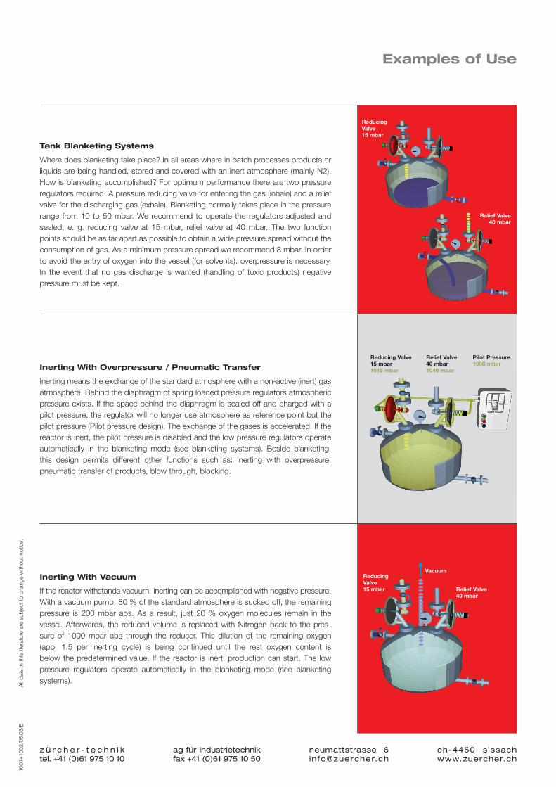
Examples of Use
Tank Blanketing Systems
Wheredoesblanketingtakeplace?Inallareaswhereinbatchprocessesproductsorliquidsarebeinghandled,storedandcoveredwithaninertatmosphere(mainlyN2).Howisblanketingaccomplished?Foroptimumperformancetherearetwopressureregulatorsrequired.Apressurereducingvalveforenteringthegas(inhale)andareliefvalveforthedischarginggas(exhale).Blanketingnormallytakesplaceinthepressurerange from10 to50mbar.We recommend tooperate the regulatorsadjustedandsealed, e. g. reducing valve at 15 mbar, relief valve at 40 mbar. The two functionpointsshouldbeasfarapartaspossibletoobtainawidepressurespreadwithouttheconsumptionofgas.Asaminimumpressurespreadwerecommend8mbar.Inordertoavoidtheentryofoxygenintothevessel(forsolvents),overpressureisnecessary.In the event that no gas discharge is wanted (handling of toxic products) negativepressuremustbekept.
Inerting With Overpressure / Pneumatic Transfer
Inertingmeanstheexchangeofthestandardatmospherewithanon-active(inert)gasatmosphere.Behindthediaphragmofspringloadedpressureregulatorsatmosphericpressureexists.Ifthespacebehindthediaphragmissealedoffandchargedwithapilotpressure,theregulatorwillnolongeruseatmosphereasreferencepointbutthepilotpressure(Pilotpressuredesign).Theexchangeofthegasesisaccelerated.Ifthereactorisinert,thepilotpressureisdisabledandthelowpressureregulatorsoperateautomatically in the blanketing mode (see blanketing systems). Beside blanketing,this design permits different other functions such as: Inerting with overpressure,pneumatictransferofproducts,blowthrough,blocking.
Inerting With Vacuum
Ifthereactorwithstandsvacuum,inertingcanbeaccomplishedwithnegativepressure.Withavacuumpump,80%ofthestandardatmosphereissuckedoff,theremainingpressure is 200 mbar abs. As a result, just 20 % oxygen molecules remain in thevessel.Afterwards, the reducedvolume is replacedwithNitrogenback to thepres-sure of 1000 mbar abs through the reducer. This dilution of the remaining oxygen(app. 1:5 per inerting cycle) is being continued until the rest oxygen content isbelowthepredeterminedvalue. If thereactor is inert,productioncanstart.The lowpressure regulators operate automatically in the blanketing mode (see blanketingsystems).
z ü r c h e r - t e c h n i ktel. +41 (0)61 975 10 10
ag für industrietechnikfax +41 (0)61 975 10 50
ch-4450 sissachwww.zuercher.ch
neumattstrasse [email protected]
1001
+100
2/05
.08/
E
All
data
int
his
liter
atur
ear
esu
bjec
tto
cha
nge
with
out
notic
e.
Reducing Valve15 mbar
Reducing Valve15 mbar1015 mbar
Relief Valve40 mbar1040 mbar
Reducing Valve15 mbar Relief Valve
40 mbar
Vacuum
Pilot Pressure1000 mbar
Relief Valve 40 mbar

1001
+100
2/05
.08/
E
All
data
int
his
liter
atur
ear
esu
bjec
tto
cha
nge
with
out
notic
e.
Quality commitment "Made in Switzerland"
z ü r c h e r - t e c h n i ktel. +41 (0)61 975 10 10
ag für industrietechnikfax +41 (0)61 975 10 50
ch-4450 sissachwww.zuercher.ch
neumattstrasse [email protected]
For more than 50 years, the Swiss quality logo “Made in Switzerland“ stands for
precision and Top quality. The ZÜRCHER-TECHNIK pressure Regulators have been
developed and are being manufactured in Switzerland. We do believe in the
manufacturing location Switzerland, its competitive and know-how leadership.
Our Product Range in Medium Pressure Regulators
ww
w.2
becr
eativ
e.ch
Pressureregulatorsformediumpressuresupto16bar.Thestandarddesignareinuseforallindustrialapplications.Thesanitarydesignregulatorsaresuitableforavarietyofapplicationsinthefood&beverage,pharmaceuticalandbiotechnologyindustries.Atypicaluseofthoseregulatorsisthepressureregulationofcleansteam.
The Zürcher-Technik pressure regulator knowledge, experienceandknow-howisaresultofmorethan30yearspressureregulatorproductionandmarketing.
Zürcher-Technik develops, designs and produces pressureregulatorsinSwitzerlandforglobalmarketinganddistribution.
The high demands and needs by the chemical-pharmaceuticalindustry have led to the development of precise, corrosion resi-stantandFDAconformingpressure regulators.Specialattentionherebywasgiventotherangeofblanketingapplications(mixers,tanks,centrifuges,containers,etc.)
Zürcher-Technikwelcomescompetitionandishappytomeettheirchallenge.Ourmission statement: In the long run, acompany'ssurvivalandwellbeingdependsonitscapabilitytocomeupwithmoreinnovativesolutionsthanitscompetitors.Qualityofourser-vice,highest levelorproduct reliability,dependableperformanceand customer satisfaction represent the key portion of our dailychallenge.