Embed Size (px)
Citation preview

IGARSS 2010, Honolulu, 29th July
TanDEM-X Commissioning Phase Status
J. Hueso Gonzalez, M. Bachmann, H. Hofmann and DLR commissiong phase team

IGARSS 2010, Honolulu 29.07.2010Slide 2
New Challenges TanDEM-X Mission
Two satellites
System complexity increasedClose formation flying Coordination TanDEM-X and TerraSAR-X mission acquisitionsBi-static acquisitions and processing chain
Requirements for a high quality global DEM
Short duration of commissioning phase requiredLimited nominal overlap2.5 years for the DEM
TerraSAR-X2007 2008 2009 2010 2011 2012 2013 2014 2015
TanDEM-X
DEM Acquisition
CP

IGARSS 2010, Honolulu 29.07.2010Slide 3
Overview TanDEM-X Commissioning Phase Plan
20 km Formation Close Formation
TDX monostaticcommissioning phase
LEOP and GS checkout
Orbit drift
1 month 2,5 months
Launch 21.06.2010
Transition 20km 07.2010
Transition close formation 10.2010
2 months
Operational01.2011
Bistaticcommissioning phase
1. Make satellite operational – monostatic and bistatic2. Verify specifications3. Ensure satellite safety in close formation

IGARSS 2010, Honolulu 29.07.2010Slide 4
Launch and Early Orbit Phase (LEOP) &Ground Segment Checkout

IGARSS 2010, Honolulu 29.07.2010Slide 5
TanDEM-X Launch – June 21st 2010
TanDEM-X launch video

IGARSS 2010, Honolulu 29.07.2010Slide 6
LEOP – Orbit configurations
TDX-1 insertion 15700 km behind TSX-1
Earth rotation and time delay: both satellites acquire different regionson the same pass
Approximation of TDX-1 640km/day
Objective: reach 20 km along track separation Allows repeat pass interferograms No interferences for monostatic calibration
510-515 kmHeight~95 minPeriod11 daysRepeat cycle
97.4°, polarInclination
TSX-1 and TDX-1reference orbit characteristics
TSX-1
TDX-1
15700 km20 km

IGARSS 2010, Honolulu 29.07.2010Slide 7
LEOP & Ground Segment Checkout
Space segment checkoutSatellite activationBoom deploymentFirst contacts, telemetry
Ground station checkoutTracking, downlink, data distribution
Verification of orbit products: orbit position, attitude, baseline
Product ordering chain: planning, commanding and data dump
Thermal behaviour instrument
SAR processor checkout
required before starting the SAR system calibration

IGARSS 2010, Honolulu 29.07.2010Slide 8
First SAR Images of TDX-1 – Ukraine
River Donets
Agricultural land types
24/06/2010; HH SAR image; ascending orbit, right looking

IGARSS 2010, Honolulu 29.07.2010Slide 9
First SAR Images of TDX-1 – Ukraine
vTDX-1
vTRAIN
Azimuth displacement moving target~ vTRAIN range
azimuth
range

IGARSS 2010, Honolulu 29.07.2010Slide 10
TDX-1 Monostatic Commissioning –Pursuit Monostatic Formation
20 km

IGARSS 2010, Honolulu 29.07.2010Slide 11
TDX-1 Monostatic Commissioning Phase
Profit from TSX-1 missionExperience commissioning phaseTSX-1 with outstanding performanceSuccessful integration and verification of ground and space segment
Characteristics orbit20 km along track separation: allow monostatic calibrationHelix formation – 300 m radial, 1305 m horizontalto compensate residual Earth rotationRepeat pass acquisitions, same coverage,very small baseline
Duration 2.5 months

IGARSS 2010, Honolulu 29.07.2010Slide 12
Mono-CP: Safety Aspects
Safe Formation FlightCollision avoidance mechanismsManeuver execution, 1st helix formationAcquisition Safe Mode (ASM): magnetic torquer mode
Exclusion ZonePrevent mutual SAR illumination: damage electronicsFailure detection, isolation and recovery
Sync Warning & Inter-Satellite LinkTSX-1 – TDX-1 real time mutual health checkContingency handling in ASMDisable transmission when neighbor satellite is not nominal
IGARSS 2010, Honolulu 29.07.2010Slide 13
Mono-CP: Calibration and Performance
SAR External CalibrationCampaigns for deploying point targets and rainforest acquisitionsGeometric, antenna model, radiometric
Internal CalibrationTRM accuracy and stability Monitor instrument drift, replica quality
Overall SAR PerformanceCommanding, timing, instrument settingsRadiometric parameters: NESZ, ASR, resolution
Product VerificationDoppler centroid and pointing verificationImage quality, coverage
Ensure quality for TerraSAR-X mission products

IGARSS 2010, Honolulu 29.07.2010Slide 14
Bistatic Commissioning –Close Formation

IGARSS 2010, Honolulu 29.07.2010Slide 15
Bi-static Commissioning Phase
Duration: 55 days
Close formation 0m average along track500m cross-track baseline
First bistatic cycleGround stations networkRoll steeringComplete bistatic chain: order, commanding, processorBaseline offset calibration
DEM calibration tests
Flight Qualification ReviewNominal DEM acquisition should begin

IGARSS 2010, Honolulu 29.07.2010Slide 16
TanDEM-X Global Test Sites
0° - Equator
30°N
60°N
30°S
60°S

IGARSS 2010, Honolulu 29.07.2010Slide 17
Highlights

IGARSS 2010, Honolulu 29.07.2010Slide 18
Highlights
1. Accurate injection in orbit
2. Satellite control High attitude and orbit stabilitySuccessful Acquisition Safe Mode test
3. First SAR image three days after launch
4. First interferogram incorporating both satellites after 26 days
5. Excellent status of the ground segment chains for TerraSAR-X and TanDEM-X acquisitions
CommandingProcessingDownlink
220 m± 2 kmAltitude
TDX-1ExpectedInjection parameter
0.0095 deg± 0.04 degInclination
No showstoppers at all!
IGARSS 2010, Honolulu 29.07.2010Slide 19
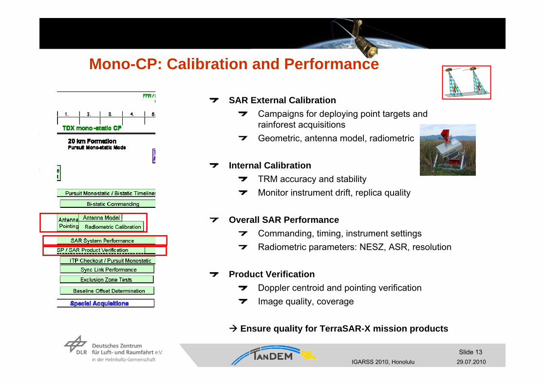
TanDEM-X first interferogram and DEM (I)
Repeat pass on 15/07/2010: 48s/370 km separationLarge along track distance: different coverage due to Earth rotation
Convergence at the poles angular velocity Earth is reduced there
TSX-1
TDX-1
Ground tracks crossat the poles

IGARSS 2010, Honolulu 29.07.2010Slide 20
TanDEM-X first interferogram and DEM (II)Rotation of range-azimuth coordinatesGround spectra can be aligned by applying squint during acquisition
Observe the same portion of the azimuth spectrum
x (range)
y (a
zim
uth)
x‘
y‘
kxk y Ground spectra
acquired at zero-Doppler
Squint correction applied
Rotated SAR coordinates Rotated ground spectrum
-0.058º bkw squintdoppler -500 Hz
0.93º fwd squint
doppler 800 Hz

IGARSS 2010, Honolulu 29.07.2010Slide 21
Results over October Revolution Island (Russian Arctic)
Coherence
DEM
SAR Image
Coherence
Interferogram
* Baseline: ~2600 m* hamb = 3m* DEM accuracy ≈ 10cm
No azimuth filter needed in interferometricprocessing

IGARSS 2010, Honolulu 29.07.2010Slide 22
Questions?
THE END


![arXiv:1706.04862v1 [physics.soc-ph] 15 Jun 2017 2007 and 2010 the German Aerospace Center (DLR) launched the EO radar satellites TerraSAR-X and TanDEM-X, respectively. In particular](https://img.dokumen.tips/doc/110x75/5ecb6f2f3e6cc57ab23d60db/arxiv170604862v1-15-jun-2017-2007-and-2010-the-german-aerospace-center-dlr.jpg)