Embed Size (px)
Citation preview

8/8/2019 Tandem Free Operation
http://slidepdf.com/reader/full/tandem-free-operation 1/53
Tandem Free Operation Simulator
for Wireless Communications
Anne Kumar
Department of Electrical Engineering
McGill University
Montreal, Canada
J a nua r y 2 0 0 1
A project submitted to the Department of Electrical Engineering in partial fulfillment of the requirements for the degree of Master of Engineering.
© 2 0 0 1 A n n e K u m a r

8/8/2019 Tandem Free Operation
http://slidepdf.com/reader/full/tandem-free-operation 2/53
i
A b s t r a c t
Speech coding is used as an effective method to achieve bandwidth efficiency.
The disadvantage of using speech compression is that it introduces signal distortion,which becomes more severe if a signal is passed through a series of coder/decoder
operations. There are encoders and decoders (or transcoders) present in the mobile
handsets as well as in the base stations. The transcoders in the base stations provide a
considerable gain in system capacity but degrade the speech quality. Any call originating
at a mobile is first converted into a compressed digital bit stream at the base station, then
decoded to a 64 kbps digital signal for transmission over the terrestrial network. If the
call destination is another mobile, another coding from 64 kbps to the compressed digital
bit stream must take place, degrading the speech signal a second time. The speech quality
may be improved if the compressed signal is not decoded at the terrestrial interface, but
rather is transmitted as a data signal to the destination mobile, avoiding one of the coding
steps.
This approach has recently been standardized as the Tandem Free Operation
(TFO) protocol. TFO bypasses the decoder if a call is destined to another mobile
telephone. The motivation behind this is that by removing the transcoding performed in
the base stations, better end-to-end speech quality is realized.
This report studies the behavior of the TFO protocol standard. TFO is applicable
only if the transmitting and destination mobiles use the same speech coding algorithms.
The standard describes two different state machines that perform the same TFO
functionality. The difference being that one state machine has additional states to handle
hand-offs and the other does not. The main goal of this report is to investigate the need
for the extra states. In this study, a high-level language is used to simulate the TFO
protocol. Specific tests are performed, such as, for local and distant hand-offs. The results
reveal that the additional hand-off information does not contribute significantly to its
performance.

8/8/2019 Tandem Free Operation
http://slidepdf.com/reader/full/tandem-free-operation 3/53
ii
A c k n o w l e d g m e n t s
I would like to express my deepest gratitude to my supervisor, Professor Maier L.
Blostein, for his continuous support, guidance, and valuable insights throughout my
graduate studies at McGill University.
I am also thankful to Professor Peter Kabal for his useful advice and knowledge
during my graduate studies and throughout the preparation of this report.
Grateful acknowledgment is expressed to Mr. C.C. Chu from Nortel Networks for
his supervision, patience, and helpful suggestions throughout this project.
Also, I would like to convey my sincere thanks to my manager, Mr. Rafi
Rabipour for his assistance and valuable insights during this project.
Finally, I would like to express my gratitude to my family and friends for their
patience, encouragement, and support throughout my endeavors.
8/8/2019 Tandem Free Operation
http://slidepdf.com/reader/full/tandem-free-operation 4/53
iii
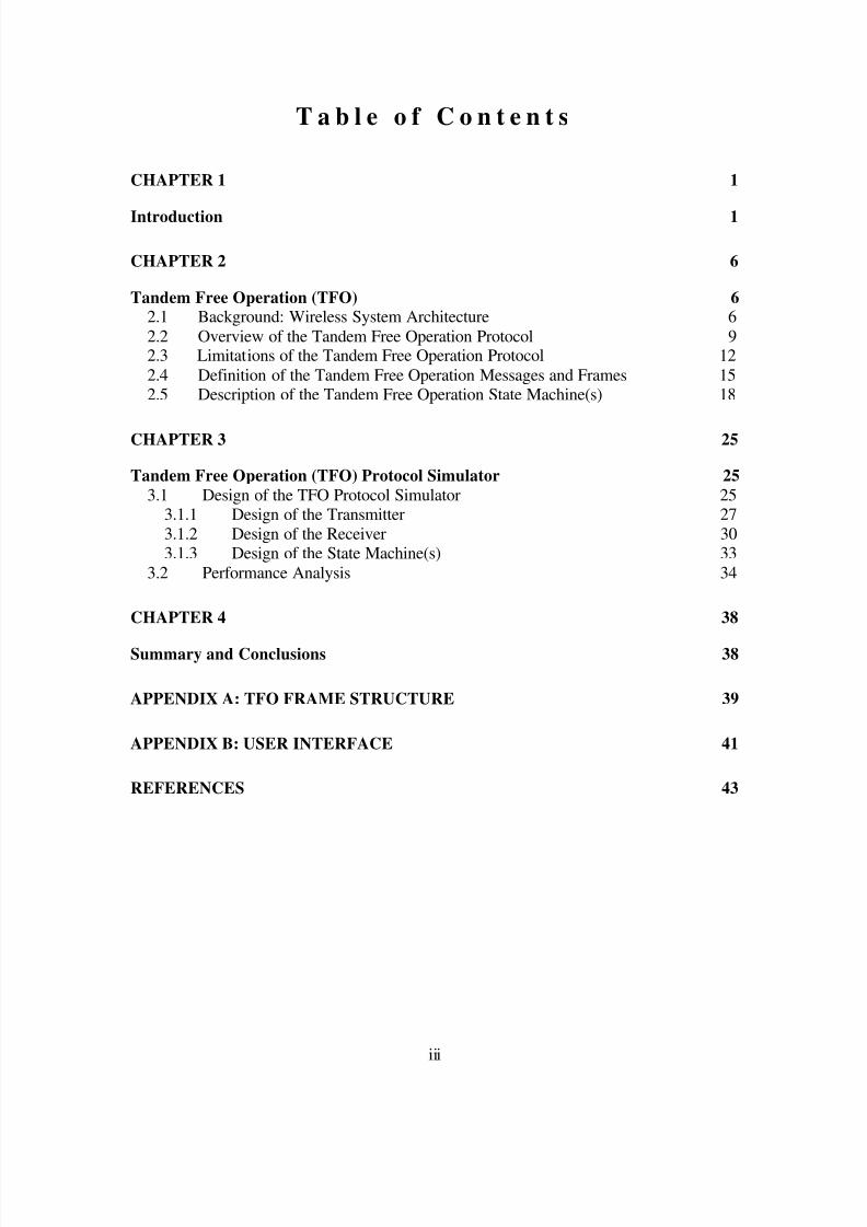
T a b l e o f C o n t e n t s
CHAPTER 1 1
Introduction 1
CHAPTER 2 6
Tandem Free Operation (TFO) 6 2.1 Background: Wireless System Architecture 6
2.2 Overview of the Tandem Free Operation Protocol 92.3 Limitations of the Tandem Free Operation Protocol 12
2.4 Definition of the Tandem Free Operation Messages and Frames 152.5 Description of the Tandem Free Operation State Machine(s) 18
CHAPTER 3 25
Tandem Free Operation (TFO) Protocol Simulator 25 3.1 Design of the TFO Protocol Simulator 25
3.1.1 Design of the Transmitter 27
3.1.2 Design of the Receiver 303.1.3 Design of the State Machine(s) 33
3.2 Performance Analysis 34
CHAPTER 4 38
Summary and Conclusions 38
APPENDIX A: TFO FRAME STRUCTURE 39
APPENDIX B: USER INTERFACE 41
REFERENCES 43

8/8/2019 Tandem Free Operation
http://slidepdf.com/reader/full/tandem-free-operation 5/53
iv
L i s t o f f i g u r e s
FIGURE 1 GENERIC WIRELESS TELECOMMUNICATIONS SYSTEM [2] 2
FIGURE 2 GSM SYSTEM ARCHITECTURE [3] 7
FIGURE 3 GSM TRANSCODING ARCHITECTURE [2] 10
FIGURE 4 FUNCTIONAL ENTITIES FOR HANDLING OF TFO [1] 11
FIGURE 5 IN-BAND SIGNALLING STRUCTURE FOR TFO MESSAGE [1] 14
FIGURE 6 PCM FRAME FORMAT 14
FIGURE 7 IN-BAND SIGNALLING STRUCTURE FOR TFO FRAME [1] 15
FIGURE 8 CONSTRUCTION OF THE TFO_REQ MESSAGES [1] 16
FIGURE 9 A DIAGRAM OF STATE MACHINE A [1]. 19FIGURE 10 A DIAGRAM OF STATE MACHINE B [1] 20
FIGURE 11 THE TFO MESSAGING SEQUENCE 24
FIGURE 12 THE TANDEM FREE OPERATION PROCESSES [1] 26
FIGURE 13 FLOWCHART OF THE MAIN MODULE 27
FIGURE 14 FLOWCHART OF THE TFO TRANSMITTER 29
FIGURE 15 FLOWCHART OF THE TFO RECEIVER 32
FIGURE 16 FLOWCHART OF THE TFO PROTOCOL MODULE 33

8/8/2019 Tandem Free Operation
http://slidepdf.com/reader/full/tandem-free-operation 6/53
v
L i s t o f T a b l e s
TABLE 1 DESCRIPTION OF TFO MESSAGES 17
TABLE 2 RESULTS FOR BASIC FUNCTIONS 35
TABLE 3 RESULTS FOR LOCAL AND DISTANT HANDOFF 36
TABLE A 1 TFO FRAME STRUCTURE [1] 39

8/8/2019 Tandem Free Operation
http://slidepdf.com/reader/full/tandem-free-operation 7/53
vi
A b b r e v i a t i o n s a n d A c r o n y m s
ACELP Algebraic Code Excited Linear Prediction (TIA/EIA-136-410)
AMR Adaptive Multi-Rate
BS Base Station
BSC Base Station ControllerBSS Base Station Subsystem
BTS Base Transceiver System
CDMA Code Division Multiple AccessCodec Coder/Decoder
CON Contact stateCOR Continuous_Retry state
CRC Cyclic Redundancy Check
DCME Digital Circuit Multiplication Equipment
EVRC Enhanced Variable Rate Codec (TIA/EIA/IS-127-1)EFRC Enhanced Full-Rate Codec
EIA Electronic Industries AssociationETSI European Telecommunications Standards Institute
FAC Fast_Contact state (only in state machine A)
FAI Failure state (only in state machine A)FAT Fast_Try state (only in state machine A)
GSM Global System for Mobile Communications
HO Hard Handoff in the case of TIA/EIA-95; Handover with TRAU
change involved in the case of TIA/EIA-136
IPE In Path Equipment
KON Konnect state
LSB Least Significant Bit
MIS Codec Mismatch stateMON Monitor state
MS Mobile StationMSC Mobile Switching Center
NAC Not_Active state

8/8/2019 Tandem Free Operation
http://slidepdf.com/reader/full/tandem-free-operation 8/53
vii
NSS Network and Switching Subsystem
OMC Operating Maintenance CenterOPE Operation state
OSS Operating Support Subsystem
PCM Pulse Coded ModulationPER Periodic_Retry state
PSTN Public Switched Telephone Network
Q8 Speech Codec Service Option 1 for TIA/EIA-95 at 8 kbps(TIA/EIA-96-C)
Q13 Speech Codec Service Option 17 for TIA/EIA-95 at 13.3 kbps(TIA/EIA/IS-733-1)
REK Re_Konnect state (only in state machine A)
SCCP Signalling Correction Control Part
SMG Special Mobile GroupSOS Sync_Lost state (only in state machine A)
SS7 Signalling System number 7
TAN Tandem state (only in state machine B)TCME TFO Circuit Multiplication Equipment
TDMA Time Division Multiple AccessTFO_ACK TFO Acknowledgement Message
TFO_ACK_L TFO Acknowledgement Message during a codec mismatchT_Bits Time Alignment Bits
TFO Tandem Free OperationTFO_DUP TFO Distant Handoff message
TFO_FILL TFO Fill MessageTFO_TRANS TFO Transparent Mode Message
TFO_NORMAL TFO Normal Mode MessageTFO_REQ TFO Request Message
TFO_REQ_L TFO Request Message during codec mismatchTFO_SYL TFO Sync Lost Message
TIA Telecommunications Industry AssociationTRAU Transcoder and Rate Adapter Unit - this unit performs speech en-
coding and decoding on the network side of the communicationssystem according to the codec standard selected
TRX Radio transceiver stationTTL TRAU-TRX-Link
UI User Interface
US1 US 1 Codec (TIA/EIA - 136 - 430)

8/8/2019 Tandem Free Operation
http://slidepdf.com/reader/full/tandem-free-operation 9/53
viii
Vocoder Voice coder/decoderVSELP Vector Sum Excited Linear Predictive Coding (TIA/EIA–136–420)
WAK Wakeup state

8/8/2019 Tandem Free Operation
http://slidepdf.com/reader/full/tandem-free-operation 10/53
1
C h a p t e r 1
I n t r o d u c t i o n
Mobile communications has advanced rapidly in the recent years. The capability
to offer wireless communications to an entire population was not even conceived (by Bell
Laboratories) until the 1960s and 1970s [6-8]. The beginning of the wireless
communications era is attributed to the development of solid-state radio frequency
hardware in the 1970s. The recent exponential growth in personal communications and
cellular radio can be accredited to the new technologies of the 1970s, which have rapidly
evolved. The future growth of wireless communications will be tied closely to radio
spectrum allocations and regulatory decisions, which support or inhibit extended services.
Customer requirements and technological advances in signal processing, access and
network areas also contribute to the future advancement of mobile communications. It is
necessary to provide the user with the best speech quality available, so that the customer
is satisfied and continues to use wireless technology.
Bandwidth is a very scarce resource in wireless systems. Bandwidth efficient
modulation and speech compression techniques are employed to achieve high system
capacity. A generic mobile-to-mobile telecommunication system is shown in Figure 1. In
order to transmit a speech signal digitally, it is necessary to pass the analog speech signal
through an analog-to-digital converter and compress the data rate of the resulting digital
signal. At the receiver, the analog signal is recovered from the compressed digital signal
via a speech decoder and a digital-to-analog converter. The device that performs this task
is called a speech coder/decoder or vocoder (voice code/decoder). A speech codec
transforms the speech signal into a digital stream of data that is suitable for transmission
over the radio interface and conversely regenerates audible speech from the received data
[2]. The speech codecs are located in the Mobile Stations (MS) and the Base Stations
(BS).
As voice enters the mobile handset (or Mobile Station (MS)), the codec in the
handset converts the analog speech into a compressed digital information stream (e.g. at 8

8/8/2019 Tandem Free Operation
http://slidepdf.com/reader/full/tandem-free-operation 11/53
2
kbps by CDMA Enhanced Variable Rate Codec (EVRC) [11]). The decoder in the base
stations typically converts the compressed speech signal into a 64 kbps digital
information stream so that it can be sent over the Public Switched Telephone Network
(PSTN) using standard Pulse Code Modulation (PCM) techniques. The signal is then
routed through the PSTN to the destination base station, where the digital signal is re-
encoded to the compressed format (e.g. 8 kbps) and transmitted to the destination mobile.
Base Station A
(BS-A)
Switch A
Switch B
PSTN
Mobile Station A
(MS-A)
Mobile Station B
(MS-B)
Base Station B
(BS-B)
Figure 1 Generic wireless telecommunications system [2]
By reducing the rate for transmission of the speech signal (i.e. from 64 kbps) over
the air interface, the bandwidth requirements could decrease by several factors and the
system capacity increases by the same factor. But, the disadvantage of using speech
compression is that it introduces signal distortion, which, of course, reduces speechquality. The distortion becomes more severe if a signal is passed through a series of
codec operations. The noise introduced by the additional encoder deteriorates the speech
parameters that are used to decode the speech signal. This makes it more difficult for the
decoder to reconstruct the speech signal. In addition, as service providers deploy an ever-
wider cross-section of technologies, involving increased conversion between different

8/8/2019 Tandem Free Operation
http://slidepdf.com/reader/full/tandem-free-operation 12/53
3
protocols carrying voice services, the problem intensifies. Initiatives to address these
problems include the development of new codec standards, such as the Enhanced Full
Rate (EFR) [12] and the Adaptive Multi-Rate (AMR) codecs [13], which are designed to
optimize system performance with improved speech quality with substantial bandwidth
economy.
Thus, the decoding and then encoding processes at the base stations provide a
considerable gain in system capacity but can potentially degrade the speech quality. In
Figure 1, it is clear that any call originating at a mobile is first converted to a compressed
digital signal (e.g. 8 kbps) at a base station, then to a 64 kbps digital signal for
transmission over the PSTN network. If the call destination is another mobile, another
coding from 64 kbps to the compressed speech signal must take place, degrading the
speech signal a second time. The speech quality may be improved if the compressed
speech signal is not coded at the PSTN interface, but rather is transmitted as a data signal
to the destination mobile, avoiding the transcoding step. This approach is feasible only if
the transmitting and destination mobiles use the same speech coding algorithms. The
European Telecommunications Standards Institute (ETSI) as Global System for Mobile
Communications (GSM) and separately by the Telecommunications Industry Association
(TIA) [1] has standardized the Tandem Free Operation (TFO) protocol recently. The
protocol can be used to raise the quality and performance of the wireless transmission
environment for the case of like codecs. The negotiation and establishment of TFO protocol is taken care of by TFO
messages and frames. The messages and frames are transmitted using a technique called
in-band signalling. In-band signalling is where TFO signalling information is
communicated together with the traffic signal on the 64 kbps link without using
additional bandwidth. The details of this approach are described in Section 2.3.
There are several advantages of the TFO protocol standard. The benefits of TFO
are:
• Enhanced speech quality in a mobile-to-mobile call,
• Decreased delay due the elimination of the transcoding in the base stations
• Savings of bandwidth on the terrestrial network
But, there are limitations to the TFO protocol, such as:
8/8/2019 Tandem Free Operation
http://slidepdf.com/reader/full/tandem-free-operation 13/53
4
• Communicating between different speech coding standards is not supported
• Multi-party calling is not supported
• Digital transparency cannot be guaranteed in all configurations of mobile-to-
mobile calls, such as when there are In-Path Equipments (IPEs) that do not
support TFO
The TFO protocol standard is new and not widely deployed. The design of the
protocol is based on the state machine concept. The TFO standard [1] describes two
different state machines for TDMA and CDMA. They perform the same functions except
one of them (i.e. state machine A for TDMA only) contains explicit states and messages
to handle handoffs1
and the other (i.e. state machine B for CDMA only) does not. In state
machine B, TFO is re-negotiated and established after a hard handoff. But, for the
purposes of this project, hard handoff is only simulated.
In order to benefit from the advantages of this recent technology, it is helpful to
implement a high-level language simulation of the standard before using valuable
resources to build a Digital Signal Processor (DSP) model. Also, a simulation system
assists in understanding, testing and examining implementation issues of the TFO
protocol standard. For example, with a simulator it is easy to change the functionality of
the protocol or verify specific scenarios, which may reveal problems with the standard or
implementation. One of the goals of the simulation tool is to find problems and/or issuesin the standard and try to resolve them before spending the time and effort in
implementing a prototype.
The main objective of this project is to find out if state machine B is a sufficient
model for the TFO protocol without limiting the performance of the standard. One way of
doing this is to use the high-level language (i.e. C) simulator and test specific scenarios
that may eliminate certain states that are redundant. Elimination of states and messages
reduces the complexity and decreases errors, such as deadlocks and/or race conditions. In
addition, verifying the correctness of the TFO protocol is made easier once the number of
states and messages is reduced. Since, only specific functionality of the TFO protocol is
1The act of transferring communication with a subscriber station from one base station to another. Hard
handoff is described by the temporary disconnection of the traffic channel. Soft handoff is characterized by
simultaneous communication with a subscriber by more than one base station.

8/8/2019 Tandem Free Operation
http://slidepdf.com/reader/full/tandem-free-operation 14/53
5
tested, the simulation package does not have to implement all of the aspects of the TFO
protocol standard.
The TFO protocol algorithms described in [1] have been implemented and
verified. A general study of the protocol was conducted and it was found that the
simplification or optimization of the standard protocol requires further testing and
modifications to the existing design. A performance analysis has been carried out in order
to observe how the TFO protocol behaves in specific situations, such as local and distant
handoffs. These will be described in detail in Chapter 3.
A variety of scenarios have been tested including:
• Basic functionality of the TFO protocol
o Basic operation of TFO (i.e. negotiation and establishment
phases of the protocol)
o Loop-back tests
o Bit Error Rate (BER) (i.e. injecting specific amount of errors
into the message stream) and other basic tests
• Specific functionality of the TFO protocol
o Local handoffs
o Distant handoffs
The organization of the report is as follows. First, in chapter 2, a brief descriptionof the architecture of a typical wireless is presented followed by an overview of the TFO
protocol followed by a more detailed explanation of elements of the standard such as in-
band signalling, TFO messaging, TFO frames and TFO state machines. Chapter 3
presents the design of the simulator package followed by a performance analysis. Finally,
Chapter 4 concludes the report by providing a short review of the results.

8/8/2019 Tandem Free Operation
http://slidepdf.com/reader/full/tandem-free-operation 15/53
6
C h a p t e r 2
T a n d e m F r e e O p e r a t i o n ( T F O )
2.1 Background: Wireless System Architecture
In order to understand tandem free operation, it is essential to explain the
architecture of a wireless system. These concepts form the foundation for the information
contained in the subsequent chapters. There are three major second generation (2G)
wireless systems:
• Global System for Mobile (GSM)
• Time Division Multiple Access (TDMA)
• Code Division Multiple Access (CDMA)
For the purposes of this project, the details of these systems will not be discussed and are
not important. Without loss of generality an overview of the Global System for Mobile
(GSM) system will be presented. A diagram of the various interfaces used in GSM is
shown in Figure 2.
The GSM architecture is made up of three main interconnected sub-systems that
interact between themselves and with the users through network interfaces. The
subsystems are the Base Station Subsystem (BSS), Network and Switching Subsystem
(NSS) and the Operating Support Subsystem (OSS).

8/8/2019 Tandem Free Operation
http://slidepdf.com/reader/full/tandem-free-operation 16/53

8/8/2019 Tandem Free Operation
http://slidepdf.com/reader/full/tandem-free-operation 17/53
8
and the controller is in contact with the switches of the switching subsystem as shown in
Figure 2. The transceiver stations are the transmission equipment and the base station
controller is the managing equipment. An important component of the base station is the
Transcoder/Rate Adapter Unit (TRAU or speech codec unit). This unit supports the
multiplexing (or decoding/encoding) of speech data to and from the interface between the
controller and the transceiver station as well as the rate adaptation in the case of data.
This interface is standardized and carries maintenance and traffic data.
The speech codec unit can be situated away from the transceiver stations and can
be placed between the controller and the Mobile Switching Center (MSC). The mobile
switching center is the basic switching functionality within the switching subsystem,
whose main purpose is to coordinate and set-up calls between the users. The remote
position of the speech codec unit allows for more compressed transmission between the
transceiver station and the speech codec unit.
The base station controller is responsible for the radio interface management
through the remote control of the base transceiver station and the Mobile Station (MS)
(i.e. cellular phone). These responsibilities include the handover management and the
allocation and release of radio channels. The controller is a small switch with substantial
computational capability. The controller is connected to several transceiver stations on
one side and the switching subsystem on the other side.
The interface between a mobile switching center and a controller uses the
Signalling System number 7 (SS7) [10] protocol called the Signalling Correction Control
Part (SCCP), which supports communication between the mobile switching center and
the base station, as well as network messages between subscriber and the mobile
switching center. This interface permits the service provider to use base stations and
switching equipment that are vendor independent.
The network and switching subsystem, consists of the main switching functions of
GSM, as well as the databases required for subscriber data and mobility management. It
is sometimes called the switching subsystem. The main objective of the switching
subsystem is to coordinate the communications between the wireless system users and
other telecommunication users.

8/8/2019 Tandem Free Operation
http://slidepdf.com/reader/full/tandem-free-operation 18/53
9
The Operation Support Subsystem (OSS) supports several (or possibly one)
Operation Maintenance Center(s) (OMC), which are used to monitor and preserve the
performance of each mobile station, base station, base station controller, and mobile
switching center within the wireless system. The support subsystem has three main
functions:
1. Maintain all telecommunications hardware and network operations
2. Oversee all payment procedures
3. Manage all mobile equipment in the system
An operation maintenance center is devoted to each of these tasks and has provisions for
changing all base station parameters and billing procedures as well as offering system
operators with the ability to determine the performance and integrity of each piece of
subscriber equipment in the system [3].
2.2 Overview of the Tandem Free Operation
Protocol
The objective of TFO protocol is to bypass the intermediate stages of encoding
and decoding (i.e. transcoding) in the base stations in a mobile-to-mobile call to leaveonly the coding processes on the terminal equipments. This bypass would alleviate the
tandem codec effect, thus resulting in less degradation due to speech coding.
A diagram of the GSM speech transcoding architecture is shown in Figure 3. For
the following explanation, MS-A is the source mobile and MS-B is the destination
mobile. As mentioned earlier, since the switches typically work in the 64 kbps domain,
the call has to be decoded to 64 kbps (at TRAU A) and then back to 16 kbps at the far-
end encoder (TRAU B). The 16 kbps channel in Figure 3 is specifically for the GSM
coding architecture and refers to the bandwidth of the link or pipe between the base
station transceiver and base station controller. The rate of the compressed digital
information stream transmitted on the air interface varies according to the codec used in
the wireless systems (e.g. CDMA EVRC produces a 8 kbps digital information stream or
GSM EFR that produces a 12.2 kbps digital information stream).
8/8/2019 Tandem Free Operation
http://slidepdf.com/reader/full/tandem-free-operation 19/53
10
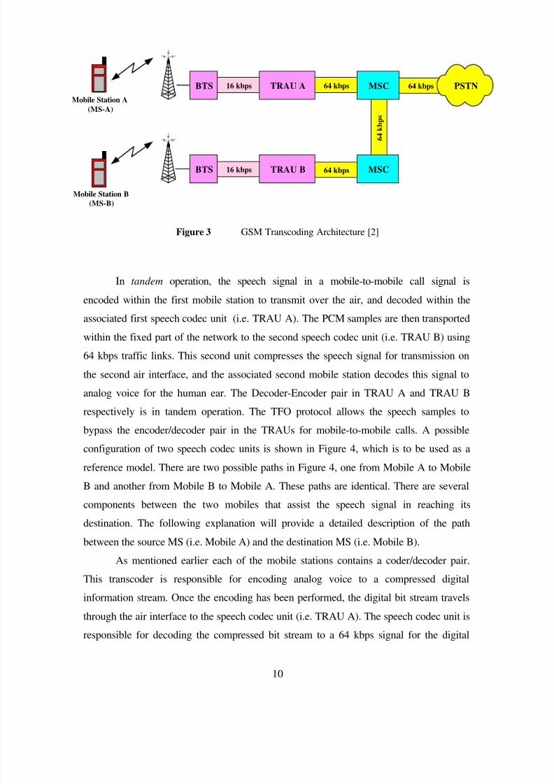
Figure 3 GSM Transcoding Architecture [2]
In tandem operation, the speech signal in a mobile-to-mobile call signal is
encoded within the first mobile station to transmit over the air, and decoded within the
associated first speech codec unit (i.e. TRAU A). The PCM samples are then transported
within the fixed part of the network to the second speech codec unit (i.e. TRAU B) using
64 kbps traffic links. This second unit compresses the speech signal for transmission on
the second air interface, and the associated second mobile station decodes this signal to
analog voice for the human ear. The Decoder-Encoder pair in TRAU A and TRAU B
respectively is in tandem operation. The TFO protocol allows the speech samples to
bypass the encoder/decoder pair in the TRAUs for mobile-to-mobile calls. A possible
configuration of two speech codec units is shown in Figure 4, which is to be used as a
reference model. There are two possible paths in Figure 4, one from Mobile A to Mobile
B and another from Mobile B to Mobile A. These paths are identical. There are several
components between the two mobiles that assist the speech signal in reaching its
destination. The following explanation will provide a detailed description of the path
between the source MS (i.e. Mobile A) and the destination MS (i.e. Mobile B).
As mentioned earlier each of the mobile stations contains a coder/decoder pair.
This transcoder is responsible for encoding analog voice to a compressed digital
information stream. Once the encoding has been performed, the digital bit stream travels
through the air interface to the speech codec unit (i.e. TRAU A). The speech codec unit is
responsible for decoding the compressed bit stream to a 64 kbps signal for the digital
BTS
BTS
TRAU A
TRAU B
MSC
MSC
Mobile Station A
(MS-A)
Mobile Station B
(MS-B)
16 kbps
16 kbps 64 kbps
64 kbps 64 kbps PSTN
6 4
k b p s

8/8/2019 Tandem Free Operation
http://slidepdf.com/reader/full/tandem-free-operation 20/53
11
IPE
IPE
PCM Samples
TFO_Messages
TFO_Frames
64 kBit/s
64 kBit/s
TFO_Protocol
DL_TFO
UL_TFO
Decoder
Encoder
TFO_Protocol
DL_TFO
UL_TFO
Decoder
Encoder
TRAU BTRAU A
UL TRAU
Frames
DL TRAU
Frames
DL TRAU
FramesUL TRAU
Frames
TRX
B
Mobile
B
TRX
A
Mobile
A
Encoder
DecoderEncoder
Decoder
Digital
Network
MSC A MSC B
Radio Leg A Radio Leg B
network. TRAU A also contains the TFO_Protocol block, which contains the TFO
protocol functionality and controls the switch that decides between bypassing the decoder
or not. If the TFO protocol conditions are satisfied, the signal will bypass the decoder and
the 16 kbps signal will be transmitted using a technique called in-band signalling.
The digital network is made up of several different components, some of which
are the In Path Equipment (IPE), such as echo cancellors, Digital Circuit Multiplication
Equipments (DCMEs), etc. The TFO Protocol also has to ensure that the path between
the speech codec units is clear. This is carried out during the TFO negotiation process
with TRAU B. Once this and the other requirements of TFO are ensured, the compressed
traffic signal is transmitted to TRAU B, where it performs the reverse process of TRAU
A and passes the digital bit stream to Mobile B so that it may be decoded for human
perception.
Figure 4 Functional Entities for Handling of TFO [1]

8/8/2019 Tandem Free Operation
http://slidepdf.com/reader/full/tandem-free-operation 21/53
12
2.3 Limitations of the Tandem Free Operation
Protocol
There are two major steps in order to communicate using the TFO protocol;
negotiation and establishment (or operation). TFO messages are used in order to
negotiate a TFO connection. After negotiation has succeeded, TFO frames are exchanged
so that TFO can be established (or operational). TFO negotiation and operation are based
on in-band signalling. The objective of TFO negotiation is to check if the:
• Call is mobile-to-mobile;
• Both TRAUs contain TFO functionality;
• Wireless coding standards match (i.e. a mobile using a GSM coding standard
communicates with another mobile using the GSM coding standard)
• Codecs match
• Path between the speech codec units (i.e. TRAUs) are digitally transparent (or
clear)
First, it is necessary to ensure that the call is mobile-to-mobile. If this is not the
case and the call is mobile-to-land (or land-to-mobile) then the conversion to 64 kbps is
necessary. In addition to the previous requirement, the TRAUs must identify each other
as TFO capable.
In the case of call transfers, the new call route is evaluated and TFO is applied if
possible, otherwise normal operation applies. In addition, for multiparty calls, TFO is not
applicable. As a result, when a two-party TFO call is extended to multi-party TFO
negotiation will fail, all the links are reverted to normal operation automatically.
Another important issue during negotiation is the compatibility between the
different wireless coding standards. The TFO protocol does not support different wireless
coding standards communicating with each other. If, for example, MS-A was using the
CDMA coding standard IS-127 EVRC and MS-B was using the TDMA coding standard
IS-641 EFRC, the extra transcoding will be performed since TFO is not supported in this
situation. In this case, the quality of speech is degraded. In addition, during the

8/8/2019 Tandem Free Operation
http://slidepdf.com/reader/full/tandem-free-operation 22/53
13
negotiation phase, the codecs at each of the base stations are also checked. If the codecs
in the radio legs do not match, TFO will not be established.
A final and important issue in establishing TFO is the need for digital
transparency. Digital transparency means that the digital content transmitted by a speech
codec unit is not modified during transmission. In other words, the user traffic and TFO
signalling information are transmitted as a digital data stream on the PSTN interface,
unaffected by the in-path equipment. When digital lines are used, the distortion to the
signal is mainly due to the use of in path equipment. The in path equipment must
therefore be disabled or configured in such a way that the information (signalling and
speech) required for TFO is not altered. The TFO messages follow a generic structure,
which allows identifying and bypassing them by the equipment, without detailed
knowledge of the protocol served. As part of the TFO establishment, if TFO can be
successfully established (i.e. both stations contain the same codec type etc.) then each
speech codec unit sends TFO negotiation messages (i.e. Go transparent commands)
which indicate to the In Path Equipment (IPE) along the base station subsystem the type
of IPE transparency mode. The main limitation of the TFO in-band signalling technique
is that the digital transparency of the PSTN interface behind the mobile switching centers
cannot be guaranteed in all the configurations of mobile-to-mobile calls.
The in-band signalling technique for TFO negotiation consists of replacing the
Lowest Significant Bit (LSB) of every 16th
consecutive PCM sample with one bit of the
TFO message, which is transferred on 64 kbps links as shown in Figure 5. This provides
for a channel (0.5 kbits/s) where the degradation on speech quality due to the bit stealing
is inaudible. This in-band signalling approach is reliable and ensures high throughput
signalling. A diagram of the PCM sample (or byte) format with the embedded frame and
message is shown in Figure 6.

8/8/2019 Tandem Free Operation
http://slidepdf.com/reader/full/tandem-free-operation 23/53
14
Figure 5 In-band signalling structure for TFO message [1]
Figure 6 PCM sample format with (a) TFO message and (b) TFO Frame
During Tandem Free Operation, TFO Frames are also transmitted using in-band
signalling. But, the difference between the TFO message and the TFO frame is that the
TFO frame has a fixed size of 320 bits (length is 20 ms) and is transmitted in the two
least significant bits of the PCM samples, which is shown in Figure 7. TFO messages are
sent prior and in parallel to these TFO Frames on the PSTN interface.
(a)
8 bit PCM sample at 64 kbps
7 bits of PCM sample
1 bit for TFO message
LSBBit 1MSB Bit 2Bit 3Bit 4Bit 6 Bit 5
LSBBit 1MSB Bit 2Bit 3Bit 4Bit 6 Bit 5
2 bits for TFO frame
(b)
6 bits of PCM sample
1 2 16 17 18 32 33 N*16 1 PCM Sample
LSBBit 2Bit 3
MSBBit 7
sµ125
One TFO message or a series of TFO messages Next TFO message

8/8/2019 Tandem Free Operation
http://slidepdf.com/reader/full/tandem-free-operation 24/53
15
Figure 7 In-band signalling structure for TFO Frame [1]
2.4 Definit ion of the Tandem Free Operation
Messages and Frames
TFO messages are used for negotiation and throughout tandem free operation as a
means for communication. The TFO messages are made up of three fields, including:
• Header
• Command (i.e. REQ, ACK, DUP, SYL etc.)
• Extensions
Figure 8 shows the construction of one of the TFO messages. The header is afixed pattern made up of 20 bits and is used to signal the beginning of a TFO message.
The command field consists of 10 bits and is used to differentiate the types of messages
sent and is described in Table 1. There are 0, 1 or 2 extension(s) after the command field
and the length of this field is 20 bits. It contains sub-fields that consist of: the signature
(which is an 8 bit random number to facilitate the detection of circuit loop back
conditions and to identify the message sources), a CRC field, codec list and
synchronization bits. For example, the TFO_REQ message consisting of a Header field,
a REQ field, a System_Identication field, and a TFO_Req_Extension field takes 140 ms
for transmission as shown in Figure 8.
TFO_TRANS
MessageT_Bits Embedded TFO_TRANS Message
LSBBit 2
MSBBit 7
Bit 3
Speech Frame 0
PCM Samples
Speech Frame 1
PCM Samples
Speech Frame 2
PCM Samples
Speech Frame 3
PCM Samples
TFO_FRAME 1 TFO_FRAME 2 TFO_FRAME 3
8/8/2019 Tandem Free Operation
http://slidepdf.com/reader/full/tandem-free-operation 25/53
16
20 Bits
Header REQ System_Identification
10 Bits
TFO_Req_Extension
20 Bits 20 Bits
40 ms 40 ms
20 Bits
Codec_List_Extension
40 ms40 ms 20 ms
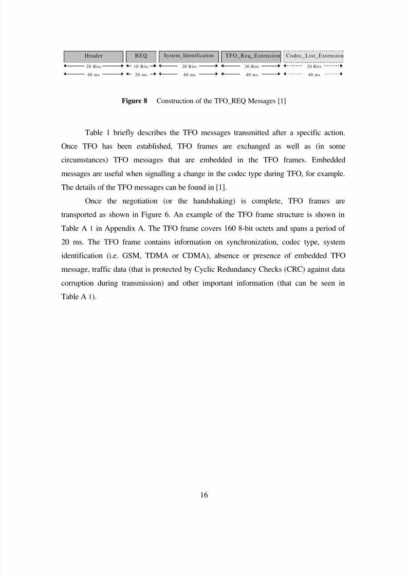
Figure 8 Construction of the TFO_REQ Messages [1]
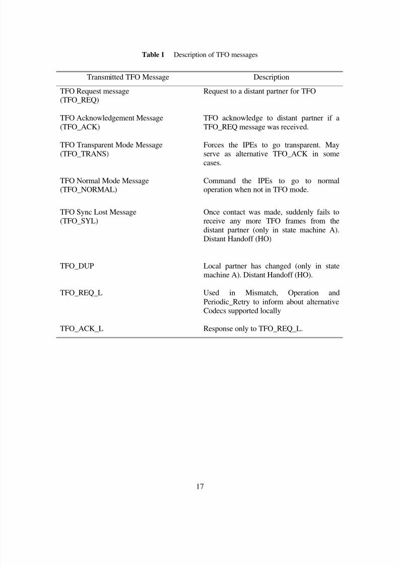
Table 1 briefly describes the TFO messages transmitted after a specific action.
Once TFO has been established, TFO frames are exchanged as well as (in some
circumstances) TFO messages that are embedded in the TFO frames. Embedded
messages are useful when signalling a change in the codec type during TFO, for example.
The details of the TFO messages can be found in [1].
Once the negotiation (or the handshaking) is complete, TFO frames are
transported as shown in Figure 6. An example of the TFO frame structure is shown in
Table A 1 in Appendix A. The TFO frame covers 160 8-bit octets and spans a period of
20 ms. The TFO frame contains information on synchronization, codec type, system
identification (i.e. GSM, TDMA or CDMA), absence or presence of embedded TFO
message, traffic data (that is protected by Cyclic Redundancy Checks (CRC) against data
corruption during transmission) and other important information (that can be seen in
Table A 1).
8/8/2019 Tandem Free Operation
http://slidepdf.com/reader/full/tandem-free-operation 26/53
17
Table 1 Description of TFO messages
Transmitted TFO Message Description
TFO Request message
(TFO_REQ)
Request to a distant partner for TFO
TFO Acknowledgement Message
(TFO_ACK)
TFO acknowledge to distant partner if a
TFO_REQ message was received.
TFO Transparent Mode Message(TFO_TRANS)
Forces the IPEs to go transparent. Mayserve as alternative TFO_ACK in some
cases.
TFO Normal Mode Message(TFO_NORMAL)
Command the IPEs to go to normaloperation when not in TFO mode.
TFO Sync Lost Message(TFO_SYL)
Once contact was made, suddenly fails toreceive any more TFO frames from the
distant partner (only in state machine A).Distant Handoff (HO)
TFO_DUP Local partner has changed (only in statemachine A). Distant Handoff (HO).
TFO_REQ_L Used in Mismatch, Operation and
Periodic_Retry to inform about alternativeCodecs supported locally
TFO_ACK_L Response only to TFO_REQ_L.
8/8/2019 Tandem Free Operation
http://slidepdf.com/reader/full/tandem-free-operation 27/53
18
2.5 Description of the Tandem Free Operation
State Machine(s)
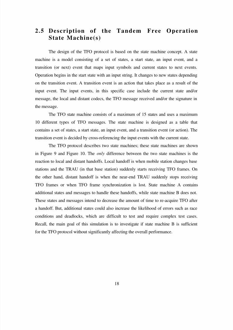
The design of the TFO protocol is based on the state machine concept. A state
machine is a model consisting of a set of states, a start state, an input event, and a
transition (or next) event that maps input symbols and current states to next events.
Operation begins in the start state with an input string. It changes to new states depending
on the transition event. A transition event is an action that takes place as a result of the
input event. The input events, in this specific case include the current state and/or
message, the local and distant codecs, the TFO message received and/or the signature in
the message.
The TFO state machine consists of a maximum of 15 states and uses a maximum10 different types of TFO messages. The state machine is designed as a table that
contains a set of states, a start state, an input event, and a transition event (or action). The
transition event is decided by cross-referencing the input events with the current state.
The TFO protocol describes two state machines; these state machines are shown
in Figure 9 and Figure 10. The only difference between the two state machines is the
reaction to local and distant handoffs. Local handoff is when mobile station changes base
stations and the TRAU (in that base station) suddenly starts receiving TFO frames. On
the other hand, distant handoff is when the near-end TRAU suddenly stops receiving
TFO frames or when TFO frame synchronization is lost. State machine A contains
additional states and messages to handle these handoffs, while state machine B does not.
These states and messages intend to decrease the amount of time to re-acquire TFO after
a handoff. But, additional states could also increase the likelihood of errors such as race
conditions and deadlocks, which are difficult to test and require complex test cases.
Recall, the main goal of this simulation is to investigate if state machine B is sufficient
for the TFO protocol without significantly affecting the overall performance.

8/8/2019 Tandem Free Operation
http://slidepdf.com/reader/full/tandem-free-operation 28/53
19
Figure 9 A diagram of state machine A [1].
Note this state machine has additional states, (i.e. Fast_Try, Fast_Con, Re_Kon andSync_Lost) that explicitly handle local and distant handoffs. Also, the Failure state
replaces the Tandem state of state machine B.
Fast_Try
First_Try C_Retry P_Retry Monitor
Contact
Mismatch
Konnect
Operation
Sync_Lost
Failure
Wakeup
Not_Active
Fast_Con
Establishment
Initialization
Re_Kon
Local
Handoff
Distant Handoff
8/8/2019 Tandem Free Operation
http://slidepdf.com/reader/full/tandem-free-operation 29/53
20
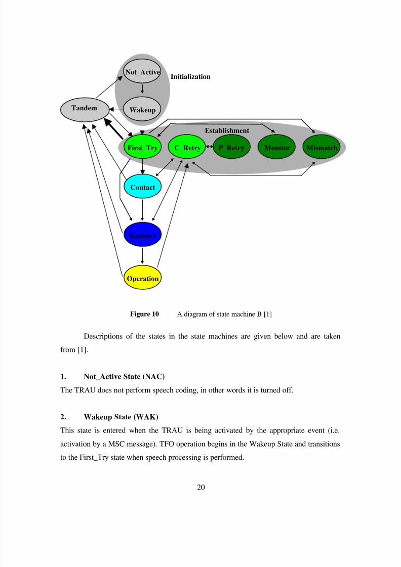
Figure 10 A diagram of state machine B [1]
Descriptions of the states in the state machines are given below and are taken
from [1].
1. Not_Active State (NAC)
The TRAU does not perform speech coding, in other words it is turned off.
2. Wakeup State (WAK)
This state is entered when the TRAU is being activated by the appropriate event (i.e.
activation by a MSC message). TFO operation begins in the Wakeup State and transitions
to the First_Try state when speech processing is performed.
First_Try C_Retry P_Retry Monitor
Contact
Mismatch
Konnect
Operation
Wakeup
Not_Active
Establishment
Initialization
Tandem

8/8/2019 Tandem Free Operation
http://slidepdf.com/reader/full/tandem-free-operation 30/53
21
3. First_Try State (FIT)
Regular request (TFO_REQ) messages are sent onto the PSTN interface for a certain
maximum period of time. If there is no response, a Runout of TFO messages is reported
and the protocol goes into Monitor state.
4. Continuous_Retry State (COR)
TFO Contact had existed, but was interrupted and synchronization of the messages and or
frames was lost. The TRAU sends a maximum number of regular request (TFO_REQ)
messages continuously to test if TFO could be re-established. If transmitter reports a
Runout of TFO messages, the system enters the Periodic_Retry State.
5. Periodic_Retry State (PER)
Entered from the Continuous_Retry state, the protocol periodically sends a single request
(TFO_REQ_L) message to determine if TFO could be re-established.
6. Monitor State (MON)
The TRAU monitors the PSTN interface for TFO Messages or TFO Frames, but it does
not send TFO Messages or TFO Frames. As soon as a TFO Message from a distant
partner (a TRAU) has been received, it transits into the Continuous_Retry state.
7. Mismatch State (MIS)
A distant TFO Partner exists, but the Codecs do not match. It tries to resolve the
mismatch by sending the mismatch request (TFO_REQ_L) message, which contains a list
of other codecs that can be used. Once TFO_REQ_L messages are received, the MSC
tried to resolve the mismatch with a handoff, for example. If it is still not resolved and
needs the far-end TRAU to change codecs, it sends a TFO_ACK_L message. If, after this
negotiation the codec mismatch has not been resolved, the protocol transits to the Failure
state or Tandem state depending on the state machine.

8/8/2019 Tandem Free Operation
http://slidepdf.com/reader/full/tandem-free-operation 31/53
22
8. Contact State (CON)
Request (TFO_REQ) messages have been received from a distant TFO Partner. The
Codecs do match. An acknowledgment (TFO_ACK) message will be sent to check the
digital transparency of the link to the distant partner. As soon as a TFO_ACK message
from a distant partner has been received, the TRAU knows that the links in both
directions are digitally transparent. The TRAU sends TFO_TRANS message to bypass
the IPEs and starts sending TFO Frames. It transits into Konnect State.
9. Konnect State (KON)
The TRAU sends TFO Frames as long as it receives correct TFO messages. The first
received TFO Frame causes the transition into the Operation State. If no TFO Frames are
received within a certain period, the TRAU transits to the Failure (or Tandem) State.
10. Operation State (OPE)
This is the main state of the TFO Protocol. In this state, the TRAU sends and receives
TFO frames and the TFO connection is fully operational.
The states described below are only present in state machine A (as shown in Figure 9)
[1].
1. Fast_Try State (FAT)
When the TRAU in the First_Try state and suddenly receives TFO Frames and the
Codecs do match, then there is a high probability that a local Hand-Off (HO) has been
initialized from an existing TFO connection and a fast TFO establishment is likely. The
TFO_Protocol has to still check, whether the link to the distant TFO Partner is (already)
transparent. Sending the TFO_DUP message does this.
2. Fast_Contact State (FAC)
This state is entered from First_Try via Fast_Try, if TFO Frames and then loss of
synchronization (TFO_SYL) messages are received. The TRAU continues to send

8/8/2019 Tandem Free Operation
http://slidepdf.com/reader/full/tandem-free-operation 32/53
23
TFO_DUP messages, until TFO Frames are received again. Then it immediately starts to
send TFO Frames. Then the TRAU transits directly to Operation state.
3. Sync_Lost State (SOS)
If the TRAU was in Operation state and suddenly the TFO Frame synchronization is lost
then the TRAU enters the Sync_Lost State for a short while, before it transits to
Continuous_Retry.
4. Re_Konnect State (REK)
This state is entered from Operation state via the Sync_Lost state, if distant HO
(TFO_DUP) messages are received. The TRAU starts to send TFO Frames again. The
TRAU transits back to Operation State, as soon as TFO Frames are received, again.
5. Failure State (FAI) (state machine A) or Tandem State (TAN) (state
machine B)
This State is entered when the distant partner shows an incorrect behavior. The TRAU
then sends pure PCM samples onto the PSTN interface and waits for the failure to
disappear. It does not send TFO Frames or TFO Messages.
In order to help understand some of the states and transitions in the TFO state
machine(s) presented earlier, a diagram of a messaging sequence to reach Tandem Free
Operation (TFO) is shown in Figure 11, as an example of the TFO negotiation and
establishment procedure. The state transitions are shown in the Base Station 1 and 2
blocks. The blue (or dotted) and red (or solid) arrows show the transmission of a TFO
messages for station 1 and 2, respectively.

8/8/2019 Tandem Free Operation
http://slidepdf.com/reader/full/tandem-free-operation 33/53

8/8/2019 Tandem Free Operation
http://slidepdf.com/reader/full/tandem-free-operation 34/53
25
C h a p t e r 3
T a n d e m F r e e O p e r a t i o n ( T F O )
P r o t o c o l S i m u l a t o r
This section describes the development and implementation of the simulation
algorithm for the TFO protocol. The standard is given in [1]. The first section will briefly
explain the main aspects of the TFO protocol as well as algorithms that were designed to
implement the protocol. This protocol has been completely simulated but not all of the
functionality has been tested. Recall that the purpose of this simulator is to verify only
specific scenarios of the TFO protocol standard. The conditions tested mainly concentrate
on decreasing the complexity of the TFO protocol standard.
3.1 Design of the TFO Protocol Simulator
The TFO protocol simulator is functionally separated into three main processes;
the transmitter, the receiver and the TFO protocol. A diagram of the TFO processes is
shown in Figure 12. The TFO protocol standard [1] does not provide any specific details
on the design of the three different modules. Some of the detailed algorithms of these
modules have been left to the designer and are described briefly in the following sub-
sections. The designs of the three modules consider the whole protocol and follow the
specifications presented in [1].
The transmitter (Tx_TFO) and the receiver (Rx_TFO) that are on different base
stations communicate with each other through the TFO_Protocol (as can be seen in
Figure 12). The Tx_Queue is the TFO message and control buffer between the
TFO_Protocol and the transmitter. Once a complete TFO message has been received by
Rx_TFO, the message is passed to the TFO_protocol, which is an event driven state
machine design. The functionality of the TFO state machine resides in the TFO_Protocol
module. The state machine is represented by a table that contains the next action(s) to be

8/8/2019 Tandem Free Operation
http://slidepdf.com/reader/full/tandem-free-operation 35/53

8/8/2019 Tandem Free Operation
http://slidepdf.com/reader/full/tandem-free-operation 36/53
27
that should be conducted, such as, loop back, mismatch test, local handoff etc. This is
followed by the initialization procedure for the queues, buffers, etc. The three main
modules are called until the test is complete or until the user wants to end the testing
procedure.
Figure 13 Flowchart of the main module
3.1.1 Design of the Transmitter
The main purpose of the transmitter is to receive commands from a queue (i.e.
Tx_Queue, that receives commands from the TFO protocol as shown in Figure 12) and
Start
Exit
Display Menu
Initialization
Call RX_TFO moduleWhile not done
Call TX_TFO module
Call TFO_PROTOCOL
module
Is it done?
Clear allocated memory for
arrays, files etc.
Yes
No Done

8/8/2019 Tandem Free Operation
http://slidepdf.com/reader/full/tandem-free-operation 37/53
28
transmit the appropriate TFO messages and/or TFO frames to the network. The next
event and/or command is determined by the state machine (which is implemented in the
TFO protocol module) and placed in the queue. The transmitter reads the next command
from the queue and inserts the next TFO event (message or frame) into the user traffic
information speech sample as mentioned in Chapter 2 and as shown in Figure 6. A flow
chart of the transmitter is shown in Figure 14.
Each TFO message (frame) has to be transmitted completely before the Tx_TFO can
transmit a different TFO message (frame). The transmitter first checks if it is in the
process of sending anything, if it is not then it will take the next event from the queue.
Once the transmitter receives an event and TFO is operational (which means that the
system is in the Operation state of the TFO protocol) then the transmitter creates and
transmits a TFO frame. If on the other hand, TFO is not operational then either, a PCM
sample is sent or a PCM sample with an embedded bit from a TFO message is
transmitted.

8/8/2019 Tandem Free Operation
http://slidepdf.com/reader/full/tandem-free-operation 38/53
29
Figure 14 Flowchart of the TFO transmitter
Start
Is it in the process of
sending anything ?
Get message from
the TX_QUEUE
What is being sent?SWITCH (msg)
Yes
No
If TFO on
No
Yes Set msg =
SEND_FRAME
REQ
ACKIPE
DUPSYL
REQ_L
REQ_PACK_L
FILL
SEND_FRAMESEND_PCM
SEND_TFO_MSG
Exit
8/8/2019 Tandem Free Operation
http://slidepdf.com/reader/full/tandem-free-operation 39/53

8/8/2019 Tandem Free Operation
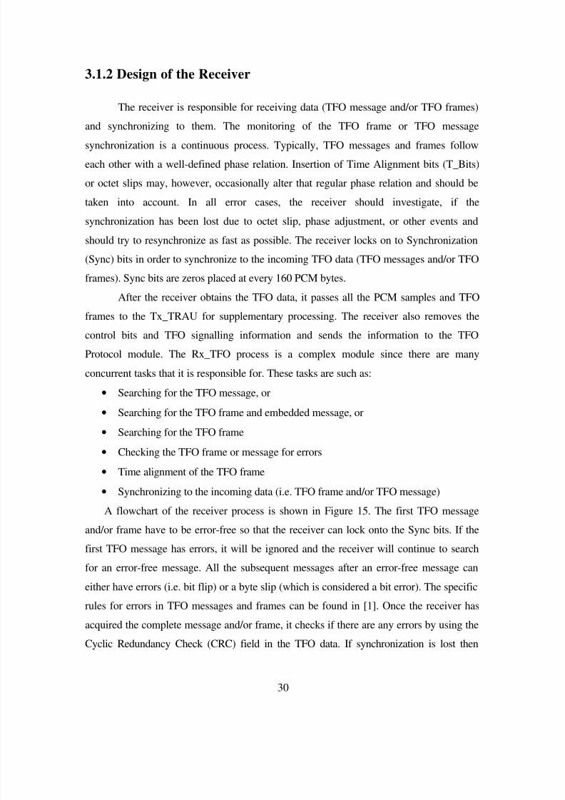
http://slidepdf.com/reader/full/tandem-free-operation 40/53
31
the receiver searches for an error-free message and/or frame as it did in the negotiation
phase.
The receiver module is responsible for many tasks. There were some issues when
creating this module, such as:
• Receiving incoming bits
• Searching for a TFO message
• Searching for a TFO frame
• Synchronizing problems
Since the TFO message is sent every 16th
PCM sample in the LSB, it is necessary
to build a receiver that would be able to efficiently retrieve the data. In order to receive
all the incoming bits and search for a message, an array to store all these bits is required.
It is also important to use a minimal amount of memory. Therefore, buffer space is
limited and in turn, search time is also reduced. Also, if a DSP implementation is taken
into account, there are limits to the size of buffers, such as tables, arrays, etc.
The receiver is designed to handle error checking, and synchronization issues. In
order to ensure that the bits are received correctly, a CRC field in the TFO message and
frame is used. Also, in the case of loss of synchronization due to a handoff or any other
interrupt; the receiver tries to re-synchronize to the incoming message using the
synchronization bits in the incoming messages or frames. Most of the aspects of thereceiver have been implemented in the TFO protocol simulator package.

8/8/2019 Tandem Free Operation
http://slidepdf.com/reader/full/tandem-free-operation 41/53
32
Figure 15 Flowchart of the TFO receiver
Start
Receive PCM byte
Extract 2 LSBs
Buffer the message or frame
If first_iteration
Yes
Search for first error-free
message or frameSet first_iteration = FALSE
Lock onto the
synchronization bits
Sync lost
No
Yes
Check all possible locations for the syncbits and the message or frame
Check every 16 bits for the
sync and the messageNo
Check message and calculate
BER
Exit
8/8/2019 Tandem Free Operation
http://slidepdf.com/reader/full/tandem-free-operation 42/53
33
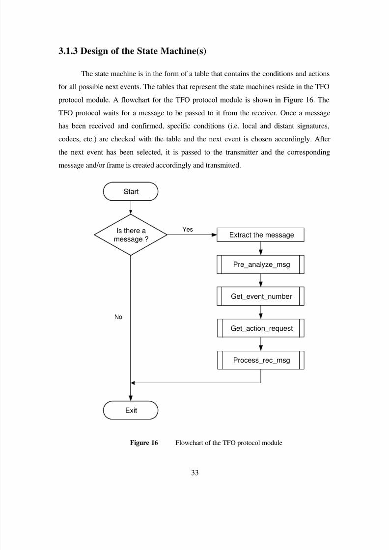
3.1.3 Design of the State Machine(s)
The state machine is in the form of a table that contains the conditions and actions
for all possible next events. The tables that represent the state machines reside in the TFO
protocol module. A flowchart for the TFO protocol module is shown in Figure 16. The
TFO protocol waits for a message to be passed to it from the receiver. Once a message
has been received and confirmed, specific conditions (i.e. local and distant signatures,
codecs, etc.) are checked with the table and the next event is chosen accordingly. After
the next event has been selected, it is passed to the transmitter and the corresponding
message and/or frame is created accordingly and transmitted.
Figure 16 Flowchart of the TFO protocol module
Start
Is there amessage ?
Extract the message
Pre_analyze_msg
Get_event_number
Get_action_request
Process_rec_msg
Yes
Exit
No

8/8/2019 Tandem Free Operation
http://slidepdf.com/reader/full/tandem-free-operation 43/53

8/8/2019 Tandem Free Operation
http://slidepdf.com/reader/full/tandem-free-operation 44/53
35
Table 2 Results for basic functions of the TFO protocol simulator
Type of state machineType of test
A B
Average amount of time to
reach operation
869 ms 869 ms
Average amount of time toresolve mismatch
458 ms N/A
Loop-back test PASS PASS
BER PASS PASS
Phase Misalignment PASS PASS
The average time to resolves a mismatch depends on the codecs that are present in
the local codec list. The time shown is an average of all the possible scenarios of codec
mismatch. The loop-back functionality in the TFO simulator was tested. It was found that
the loop-back functionality performed according to the requirements given in the
standard.
In the case of the BER test, errors were injected into the TFO messages as they
were transmitted to the far-end. In this test, random bits were flipped depending on the
percentage of errors entered by the user. Varying rates of BER were introduced and the
receiver was tested to check if it could decipher the TFO message that was originally
sent. The test results revealed that this aspect of the TFO simulator is functional.
Phase alignment and/or synchronization of the receiver were important issues
when designing this simulator. This simulator was able to successfully handle a byte slip
and other misalignment tests (i.e. testing with time alignment bits).
Since the basic functionality of the TFO simulator was successfully verified, tests
that are more specific were conducted. These tests address the goal of this project, which
was to find an approach to simplifying the TFO protocol standard. In order to do this the

8/8/2019 Tandem Free Operation
http://slidepdf.com/reader/full/tandem-free-operation 45/53
36
necessity of the additional states for handoffs was investigated. Since a complete
investigation would require more time and resources, a partial study was conducted. This
study will contribute to creating more detailed test cases for further verification. The
results of local and distant handoff for both of the state machines are shown in Table 3.
Table 3 Results for local and distant handoff
Type of state machineType of test
A B
Average amount of time to
reach operation after localhandoff
1221 ms 1547 ms
Average amount of time to
reach operation after distanthandoff
1300 ms 1347 ms
Recall that the state machine B was not equipped with the additional messages
and states to handle a local handoff. This was the reason that it took 326 ms longer (for
local handoff) to reach operation using state machine B than using state machine A. But,
the total time required to reach operation was still less than 2 seconds and state machine
B was able to successfully reach TFO mode without using additional messages. Also,
there was no major difference (47 ms) between the results of the state machines for
distant handoff. This was an important result and supported the hypothesis that the extra
messages may not be required and did not significantly hinder the performance of the
TFO protocol.
Further tests were conducted to observe the reaction to state machine B to
receiving unusual messages, such as the additional ones present in state machine A.
Preliminary results revealed that for all the previous tests discussed (i.e. such as the tests
in Table 2 and Table 3) state machine B was able to communicate effectively. This also
suggested that the smaller state machine (i.e. B) might be able to handle certain abnormal

8/8/2019 Tandem Free Operation
http://slidepdf.com/reader/full/tandem-free-operation 46/53
37
conditions, such as, receiving unfamiliar messages, which may be found in scenarios
where different versions of the standards are implemented in the two TRAUs.
Since state machine B was able to handle handoffs effectively (as shown in Table
3), this suggests that the extra states (i.e. in state machine A) may not be necessary and
could be removed. But, it is recommended that further tests be organized and investigated
to rigorously verify all possible scenarios to support the minimization of the TFO
protocol.

8/8/2019 Tandem Free Operation
http://slidepdf.com/reader/full/tandem-free-operation 47/53
38
C h a p t e r 4
S u m m a r y a n d C o n c l u s i o n s
A simulator for the TFO protocol, a new standard designed to improve the
speech transmission quality of mobile-to-mobile telephone calls in wireless networks was
implemented. The protocol is effective in situations where both mobiles are matched, i.e.
employ compatible speech coding algorithms. The simulator was used to study the
performance of the protocol in a variety of areas including the following:
• Time required to enable bypassing the transcoder stage in the base stations
• Time required to determine if mobiles are matched
• Impact of transmission errors (i.e. increasing Bit Error Rate (BER))
• Impact of phase misalignment (i.e. byte slip)
• Loop-back functionality
The TFO protocol describes two different state machines that perform similar
functions except one of them (say, state machine A) contains explicit states and messages
to handle handoffs and the other (say, state machine B) does not. This study showed that
the protocol could operate satisfactorily with state machine B, i.e. showed that theadditional hand-off provisions do not contribute significantly to its performance. Thus, a
state machine with fewer states, thereby reducing potential errors due to race conditions,
deadlocks, etc, can model the protocol adequately. It was also shown that the two state
machines were able to effectively communicate with each other, which imply that state
machine B is robust, and can handle new or undefined but valid messages reliably.
The results of this study should be viewed as preliminary and further rigorous
testing should be carried out to substantiate them. Also, although the simulator modeled
the entire protocol, this study did not fully test the correctness of all of its aspects, but
only those pertinent to our basic objective. Nonetheless, the information that was
obtained by the testing of the TFO protocol standard is beneficial and the tests can be
improved in order to verify other possible scenarios in future enhancements of wireless
architecture.

8/8/2019 Tandem Free Operation
http://slidepdf.com/reader/full/tandem-free-operation 48/53

8/8/2019 Tandem Free Operation
http://slidepdf.com/reader/full/tandem-free-operation 49/53
40
C16: Error concealment indicator. Set if the frame underwent errorconcealment treatment in the local decoder. Cleared otherwise.
C17...C110: Reserved.D1...D72: R0, LPC and subframe 1-information bits
D73...D75: CRC over R0, LPC and subframe 1 information bits
D76...D104: Subframe 2 information bitsD105...D107: CRC over subframe 2 information bitsD108...D136: Subframe 3 information bits
D137...D139: CRC over subframe 3 information bitsD140...D168: Subframe 4 information bits
D169...D171: CRC over subframe 4 information bits
Notes: VSELP encoded parameters are transmitted in the order specified in TIA/EIA-136-420 with the most significant bits transmitted first.

8/8/2019 Tandem Free Operation
http://slidepdf.com/reader/full/tandem-free-operation 50/53
41
A p p e n d i x B : U s e r I n t e r f a c e
TFO Simulator
==================================
Main Menu----------------------------------
1. Read options from default file
2. Choose options from menu3. Run Simulator
0. Quit
1Enter File Name: opt.dat
==================================
TFO Simulator
==================================
Main Menu
----------------------------------1. Read options from default file2. Choose options from menu
3. Run Simulator
0. Quit
2
STATION 1 (0) STATION 2 (1)
================================== ================================
1. State Machine (A or B) = A 16. State Machine (A or B) = A
2. Test Loop Back ST1 = 13. Set Current State ST1 = 13 17. Set Current State ST2 = 2
4. Codec List ST1 Used = 2 18. Codec List ST2 Used = 0
Sup_A = 1 Sup_A = 2
Sup_B = 1 Sup_B = 05. Byte Slip ST1 = 0 19. Byte Slip ST2 = 0
6. Time Alignment Bits = 0 20. Time Alignment Bits = 0
= TFO_FRAME 21. Message to Send = PCM_SAMPLE
8. Number of Times to send = 3 22. Number of Times to send = 0
9. Signature ST1 = 12 23. Signature ST2 = 0
10. Frame Sync Lost ST1 = 0 24. Frame Sync Lost ST2 = 0
11. Msg Sync Lost ST1 = 0 25. Msg Sync Lost ST2 = 012. Inhibit TFO ST1 = 0 26. Inhibit TFO ST2 = 0
13. Allow TFO ST1 = 0 27. Allow TFO ST2 = 0
14. Initialize Station ST1 = 0 28. Initialize Station ST2 = 0
15. Set Read/Write Q1 = 1 5 10 29. Set Read/Write Q2 = 0 45 56
Other Options (For both stations)
==================================
30. Test BER = 0
31. Set BER Value Ground = 0.000000

8/8/2019 Tandem Free Operation
http://slidepdf.com/reader/full/tandem-free-operation 51/53
42
32. Set BER Value Air = 0.000000
33. Station to Start = 0
==================================
Enter Choice (from 1-33) --------------> 0
8/8/2019 Tandem Free Operation
http://slidepdf.com/reader/full/tandem-free-operation 52/53
43
R e f e r e n c e s
[1] Telecommunications Industry Association (TIA)/Electronic Industries
Association (EIA)-829. TFO Protocol Standard Document.
[2] Kurupillai, R., Dontamsetti, M, and Cosentino, F.J., Wireless PCS: Personal
Communication Services, McGraw Hill, New York, 1997.
[3] Rappaport, T. S., Wireless Communications: Principles and Practice, IEEE Press,
New York, 1996.
[4] Mouly, M. and Pautet, M., The GSM System for Mobile Communications,
Telecom Publishing, Palaiseau, 1992.
[5] Rousell, G., “Voice Quality: Keeping the Lines Clear”, Mobile Europe,
http://www.tellabs.com/news/articles/me9099.shtml, September 1999.
[6] Noble, D., “The History of Land-Mobile Radio Communications”, IEEE
Vehicular Technology Transactions, pp. 1406–1416, May 1962.
[7] Macdonald, V. H., “The Cellular Concept”, The Bell Systems Technical Journal,
Vol. 58, pp. 15– 43, January 1979.
[8] Young, W.R., “Advanced Mobile Phone Service :Introduction, Background, and
Objectives,” Bell Systems Technical Journal, Vol. 58, pp. 1–14, January 1979.
[9] Goetz, I., “Mobile Call Quality--The Impact of Tandem Free Operation (TFO)”,
Middle East Communications, http://www.tellabs.com/news/articles, April 2000.

8/8/2019 Tandem Free Operation
http://slidepdf.com/reader/full/tandem-free-operation 53/53
[10] Van Bosse, J. G., Signalling in telecommunication networks, New York, Wiley,
1998.
[11] Telecommunications Industry Association (TIA)/Electronic Industries
Association (EIA)- IS-127-1, Enhanced Variable Rate Codec (EVRC)
[12] Telecommunications Industry Association (TIA)/Electronic Industries
Association (EIA)-136-410, Enhanced Full-Rate Voice Codec (EFRC)
[13] Telecommunications Industry Association (TIA)/Electronic Industries
Association (EIA)- 136-440, Adaptive Multi-Rate (AMR).