Embed Size (px)
Citation preview

Design, Optimization And Manufacturing Of Climbing Robots Utilizing Micro-Fiber Arrays
Ahmet Çalışa, Dr. Özgür Ünverb Master of Science, Department of Mechanical Engineering, Hacettepe University, Turkey
February 2013
____________________________________________________________________________________________________________________________
Abstract
Few climbing robots have been built using flat dry elastomer adhesives until now, and none of them have looked deeply into the wheel size and dry elastomer thickness. In this project, the effect of the adhesive thickness and the wheel radius is comprehensively observed. Furthermore, the utilization of compliant mechanisms, as well as active tail control to achieve higher adhesion forces during climbing, surface transition and overcoming obstacles are illustrated.
Key Words: Climbing robot, elastomer thickness optimization, wheel optimization.
____________________________________________________________________________________________________________________________
Introduction: 1.
Robots have been used for many years in industrial applications and daily life and their prevalence increases every day. The main reasons people use robots are: increasing public health and safety and finishing any given duty without any flaw. Climbing and executing a given duty can be done effortlessly and efficiently by climbing robots.
In recent years, there have been many studies and improvements in climbing robots. Thus, climbing robots are used actively in many missions, such as in nuclear facilities, on planes, buildings, and pipelines for inspection, surveillance, maintenance and repair.
In this work, climbing robot design is optimized dimensionally according to the ratio between adhesion and robot size. Climbing tests are examined if performance levels are met. Further studies are done to increase climbing safety and performance.
So far, dimensional optimization has not been taken into account while designing climbing robot.
Elastomer Film Peeling Models 2.
This section shows two extreme cases of peeling of elastic films analytically. These cases are; peeling only by stretching and bending. In these models quasi-static and plane strain conditions are considered. An external work
must be provided to peel the elastomer film from a surface. Then, this work is utilized both internally as an elastic deformation in the film and as an adhesive energy to keep the adhering bodies in contact with the contact area. Internal energy is also divided into two as axial and bending elastic deformation energy. The total energy balance can be shown as;
dE!"# = dE!"# + dE!"#$ (1)
Fig. 1. Peeling only by bending (a), peeling by pure stretching (b)
M
EI
dθ
R0
M
dL
a)
EA F
dL
F
α
(1-cos α)dL εdL
b)

External Work 2.1.
As seen in Fig.1 an elastic thin film can be peeled off the surface by bending (M) and pulling (F). These external actions can be applied individually or simultaneously as in the equations below;
𝑑𝐸!"# = 𝐹 𝑑𝑢 + 𝑀𝑑𝜃 (2)
It is assumed that both force and moment are applied in 2D plane.
Internal Energy 2.2.
Internal energy is related to the elastic deformations in the elastomer film due to pulling and bending which can be formulized as;
𝑑𝐸!"# =!!𝐸𝐴𝜖! 𝑑𝐿 + !
!𝐸𝐼𝜅! 𝑑𝐿 (3)
Where 𝐸 is the modulus of elasticity, 𝐴 is the cross section area of the elastic film (𝑤𝑡), 𝜖 is the strain, 𝐼 is the second moment of area (𝑤𝑡!/12), 𝜅 is the curvature, and 𝑑𝐿 is the unit peeling distance. In this equation 𝐸𝐴 and 𝐸𝐼 are related to the axial and bending stiffness, respectively. Axial stress and bending moment can be calculated as 𝐸𝐴𝜀 and 𝐸𝐼𝜅 respectively.
Contact Energy 2.3.
The contact energy is related to the adhesion between elastomer and adhered surface. This term also indicates the work of adhesion (𝑤!"!). Work of adhesion is the energy needed to separate the surfaces from each other. The contact energy can be calculated as;
𝑑𝐸!"#$ = 𝑤!"!𝑑𝐴!"#$ (4)
where, 𝑑𝐴!"#$ is the unit peeling area.
Peeling Only by Bending 2.4.
This is the extreme case of bending. As seen in Fig.1a, elastomer film detaches from the surface only due to the bending moment. In this case, external energy (because of the moment) is used to bend the material and detach it from the contact surface. This equality can be shown as;
𝑀𝑑𝜃 = !!𝐸𝐼𝜅𝑑𝜃 + 𝑤!"! 𝑤𝑅!𝑑𝜃 (5)
where, 𝜅 = 𝑅!!!, 𝑑𝐿 = 𝑅!𝑑𝜃, 𝑀 = 𝐸𝐼𝜅 and 𝐼 = 𝑤𝑡!/12. By solving equation 5;
𝑀 = !!!!!!!"!!
(6)
𝑅! =!!!
!"!!"! (7)
If the adhesive material and the surface properties are constant, then 𝑀 increases linearly with 𝑤 and non-linearly with elastomer thickness by 𝑡!/!. Likewise; 𝑅! increases non-linearly with elastomer thickness by 𝑡!/!. In addition, when the elastomer width is kept constant, then 𝑀 and 𝑅! become linearly dependent.
Peeling Only by Stretching 2.5.
This is the extreme case of stretching. As seen in Fig.1b, elastomer film detaches from the surface only due to the pulling force. In this case, created external energy is consumed to stretch the material and detach it from the contact surface. This equality can be shown as;
𝐹! 1 − 𝑐𝑜𝑠𝜃 + 𝜖 𝑑𝐿 = !!𝐸𝜖!𝑑𝐿 + 𝑤!"! 𝑤𝑅!𝑑𝐿 (8)
where, 𝐹! = 𝐸𝐴𝜖. By solving equation 8;
𝐹! = 𝐸𝑤𝑡 !!!"!!"
+ (1 − 𝑐𝑜𝑠𝜃)! − (1 − 𝑐𝑜𝑠𝜃) (9)
Optimization 3.
As seen in Fig.2 free body diagram of elastic thin film peeling of by pure stretching where Fp is peeling force, FpN is normal component of peeling force, F
shear is shear force
of elastic thin film, Fmg
is weight on the wheel due to gravity, F
S is slack force, F
t is tail force F
N, F
m is force due
to motor torque, Tm is motor torque, F
fric is friction force, Fx
is force on the wheel’s x-axis.
Fig. 2. FBD of peeling only by bending
Contact Surface
Ffric
F
Fp
FpN
Fshear
FS
Fmg
Ft
Fm
FN
FN
Fx
Tm

Fig. 3. FBD of peeling only by pure bending
In this project, legged robots are not preferred due to their complex nature, instead wheeled or tracked robots are considered. For tracked climbing robots, keeping the track on the wheel is a big challenge, therefore, wheeled type climbing robot becomes the focus of this work.
Elastomeric thin film is wrapped around the wheel and fixed to the wheel hub by strings. The main challenges of this task are the optimization of the elastomer thickness and the wheel radius.
Elastomer Stretching Force 3.1.
Using equation 9, peeling force can be found for each corresponding peeling angle assuming no moment effect. In reality, there will only one peeling angle and its corresponding peeling force due to the balance of stretching and peeling force. To find out these values, elastomer should be stretched from initial length to the final length. These lengths can be calculated as given below;
𝐿! = 2𝜋 𝑅! +!!
(10)
𝐿! = 𝑅! +!!2𝜋 − 𝜃 + 2 𝑅! +
!!tan !
! (11)
Then the stretching force can be calculated as;
𝐹!"# = 𝐸𝑤𝑡!!!!!!!
(12)
When the wheel is stationary, elastomer is its relaxed state and 𝜃 = 0. When the wheel starts to rotate, due to the surface adhesion, elastomer does not come off the surface at first and starts to elongate (stretch). Simultaneously, 𝜃 starts to increase. As the wheel rotates, 𝐹!"# and 𝜃 keep
increasing until 𝐹!"# becomes equal to 𝐹! as seen in Fig 2. At this point, transition period finishes and the elastomer detaches from the surface and this snapshot (𝜃,𝐹!"# = 𝐹!) is preserved throughout the operation assuming all parameters are constant. 𝐸 = 110 𝑘𝑃𝑎,𝑊! = 70 𝑁 𝑚 ,𝑤 =10 𝑚𝑚,𝑅! = 30 𝑚𝑚 and 𝑡 = 2 𝑚𝑚 are used to plot Fig.2. According to the plot, peeling force is 0.45 𝑁 and 𝜃 = 118 degree.
Fig. 4. Plot of peeling and stretching forces Peeling occurs when stretching force equals to the
peeling force. In this case, for every given θ and t there is only one intersection point which satisfies the equality of stretching and peeling force. This equation can be generalized as;
𝐹!"# − 𝐹! = 0 (13)
The peeling force attained from Fig. 2 does not affect the climbing performance directly. However, the normal direction of this force is used to push the robot towards the surface and to preload the elastomer. Therefore, utilizable component of the peeling force is the force perpendicular to the surface. This normal peeling force can be calculated as;
𝐹!! = 𝐹! 𝑠𝑖𝑛𝜃 (14)
Moreover, in Fig.2, it is assumed that the wheel and the elastomer are massless. However, especially for inverted climbing, mass pulls the robot away from the surface towards the ground, therefore, masses should be taken into account and should be subtracted from 𝐹!!. In this work, elastomer film and wheel hub is considered as masses. The available adhesion left from elastomer and wheel hub is going to be used to carry the robot and its accessories such as sensors and links. Mass of the elastomer can be calculated as;
𝑀! = 𝜋𝑤𝜌 𝑅! + 𝑡 ! − 𝑅!! (15)
where, 𝜌 is the material density. Mass of the wheel is calculated roughly utilizing the manufactured wheel masses which fits nicely to the equation given below for our application;
𝑀! = 0.001 + 0.2𝑅! (16)
Therefore, the total force which pulls the robot towards the ground during inverted climbing can be calculated as
Contact Surface
Ffric
F
Fp
Fmg
Ft
Frm
FN
FN
Fx
M
Tm

Table 1. Values of 𝐹!! , 𝑡, and 𝑅! for different 𝑅!/𝑅! ratios.
𝑅!/𝑅! Maximum 𝐹!! [N] Optimum 𝑡 [mm] %90 𝑡 Range [mm] Optimum 𝑅! [mm] %90 𝑅! Range [mm] 1 0.59 10.0 5.2-15.4 8.2 3.0-15.0 3 0.51 6.5 3.6 - 10.0 12.5 5.3-24.1 5 0.47 5.5 2.9-7.9 15.2 6.4-28.9 7 0.44 4.6 2.5-6.9 17.6 7.2-32.0
10 0.41 3.9 2.2-5.7 20.5 8.5-34.8 20 0.35 2.8 1.6-4.1 24.0 10.7-41.6 50 0.27 1.8 1.1-2.5 30.8 13.8-49.2
100 0.21 1.2 0.7-1.6 33.5 16.3-51.2
𝐹! = 𝑀! +𝑀! 𝑔, where 𝑔 is the gravitational acceleration. As a result effective peeling force can be expressed as;
𝐹!! = 𝐹!! − 𝐹! (17)
The equations above are valid if the bending moment is negligible. However, in some cases bending stiffness is dominant and the elastomer can peel off the surface without any extra effort when running on a wheel due to the bending moment. which does not add any adhesion to the robot. If the diameter of the wheel is equal or less then 𝑅! then the elastomer peels off the surface by itself due to the high curvature. The wheel radius must be much larger than 𝑅! to minimize the effect of bending moment. There is a relationship between tread thickness and minimum wheel radius as given in equation 6. By using equations 6 and 7 it can be seen that 𝑀 and 𝑅! are linearly dependent upon each other when tread dimensions and material are defined. In this project, wheel radius (𝑅!) is chosen to be 𝐾 times larger than 𝑅!, so that the effect of peeling due to the bending is diminished. However, note that the bending moment’s effect cannot be fully removed.
Fig. 5. Plot of elastomer thickness vs. wheel radius for pure moment
detachment
Fig. 6. Plot of wheel radius vs effective peeling force.
Fig. 7. Plot of thickness vs effective peeling force.
𝐸 = 110 𝑘𝑃𝑎,𝑊! = 70 𝑁 𝑚 ,𝑤 = 10 𝑚𝑚,𝑅!/𝑅! = 20, and 𝜌 = 1000 𝑘𝑔/𝑚!used to plot Fig.5, 6 and 7.
As seen in the Table 1., 𝐹!! makes a peak when 𝑅!/𝑅! = 1, however, in reality the elastomer peels off the surface due to pure bending, in this case. In other words, it would not improve the climbing performance due to self-peeling. As 𝑅!/𝑅! ratio increases the effect of the bending moment, effective peeling force and elastomer thickness decreases and wheel radius increases. When 𝑅!/𝑅! = 20, to get maximum 𝐹!!, 𝑡 and 𝑅! have to be set to 2.8 and 24 mm respectively. In addition, instead of getting maximum 𝐹!!, a range could be defined to get at least %90 of 𝐹!!. In this case, the designer would be more flexible when designing a robot and it would be easier to diminish the effect of the bending moment. For example, when 𝑅!/𝑅! = 20, instead of having 0.35 𝑁 as an effective peeling force, getting at least 0.315 𝑁 broadens the possibilities of the elastomer thickness from 1.6 to 4.1 𝑚𝑚, and the wheel radius from 10.7 to 41.6 𝑚𝑚. To minimize the moment effect, it would be logical to choose the minimum elastomer thickness with the maximum wheel radius as long as the other design criteria allows.
Robot Design 4.
Chassis Design 4.1.
The parameters to take into account when designing chassis for climbing robots are:
• Weight, • Tail position and length, • Hierarchal compliance,

• Position of the center of gravity.
Manufacturing constraints are taken into account when designing the chassis. A 2-axis laser cutter (Gravograph LS100Ex) is used for cutting a 3mm Plexiglas sheet. In order to provide integrity and easy assembly, sheets are designed taking into account 2-axis manufacturing.
The climbing robot is designed in a way that consists of two mirrored modules connected to each other by a shaft. Thus, even though the robot has four wheels it acts like a tripod by means of compliance. Surface transitions will ease, climbing safety will increase and it will be more agile.
Fig 8. Rocker Boogie
For stabile climbing the motors are assembled inside the wheels. Also, in order to increase adhesion area and compliance to surface discontinuities, foam inserts are used between wheel hubs and elastomer pads.
With the help of flexible structures such as foam and stitching of elastomer pads which hold them in place, a configuration similar to climbing robots with legged mechanism is created.
Adhesion Force/Weight-Dimensional Optimization 4.2.
In climbing robots the area of elastomers which provide adhesion is proportional to the robot’s length squared (𝐿!). Additionally, the weight of the robot is proportional to the robot’s length cubed (𝐿!). Due to necessary equipment to be used on the robot such as the electronic board, battery, wireless communication board, and sensors, the robot`s weight has a minimum value of approximately 75 grams without a chassis, motors, tires and tails etc.
Hence, there must be an optimum point where the adhesion force is maximized proportionally to weight.
𝐿 → 0 𝑚!"#"$ ≅ 75𝑔𝑟 (18)
𝐿 → ∞ !!
!!→ 0 (19)
Fig. 9. Chassis Length L!, Chassis Width L!, Chassis Thickness L!, Tire Contact Region Length L!, Tire Contact Region Width L!, Tail Length L!, Tail Thickness L!, Tail Width L!
The robot`s total weight 𝑚!, weight of the equipment to be used on the robot (wireless communication, sensors, etc.) 𝑚!, robot`s chassis weight 𝑚!, weight of the motors 𝑚!, weight of the robot`s tires 𝑚!, weight of the tail 𝑚!, weight of the battery is 𝑚!,
m! = m! +m! + 3m! + 2m! +m! +𝑚! (20)
All calculations are done according to one module of the robot.Rotation force for each tire can be calculated as;
𝐹!"! = 𝐹! (21)
𝐹!, is determined by adhesion model.
Motor Selection 4.3.
The motor torque, which is necessary to overcome adhesion force on each wheel, can be determined as the formula below. Motor power (𝑃!, motor torque 𝑇!, and angular speed 𝜔, tire diameter 𝑟!,
𝑇! ≅ 0.93𝑟!𝐹! (22)
𝑃! = 𝑇!.𝜔 (23)
𝑃! = 0.93𝑟!𝐹! .𝜔 (24)
𝑚! = 𝐴!𝑃!! + 𝐵!𝑃! + 𝐶! (26)
Motors which can be found easily for these kinds of applications are shown in the graph according to their power density.
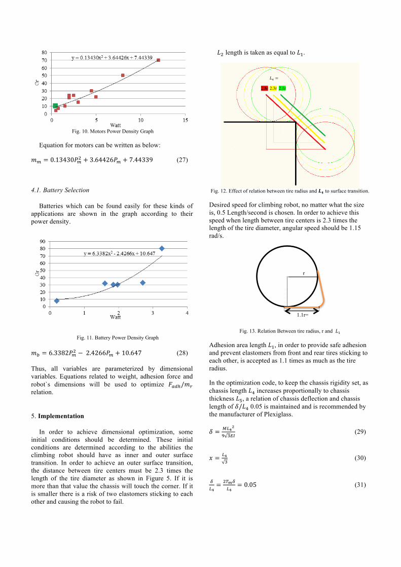
Fig. 10. Motors Power Density Graph
Equation for motors can be written as below:
𝑚! = 0.13430𝑃!! + 3.64426𝑃! + 7.44339 (27)
Battery Selection 4.1.
Batteries which can be found easily for these kinds of applications are shown in the graph according to their power density.
Fig. 11. Battery Power Density Graph
𝑚! = 6.3382𝑃!! − 2.4266𝑃! + 10.647 (28)
Thus, all variables are parameterized by dimensional variables. Equations related to weight, adhesion force and robot`s dimensions will be used to optimize 𝐹!"!/𝑚! relation.
Implementation 5.
In order to achieve dimensional optimization, some initial conditions should be determined. These initial conditions are determined according to the abilities the climbing robot should have as inner and outer surface transition. In order to achieve an outer surface transition, the distance between tire centers must be 2.3 times the length of the tire diameter as shown in Figure 5. If it is more than that value the chassis will touch the corner. If it is smaller there is a risk of two elastomers sticking to each other and causing the robot to fail.
𝐿! length is taken as equal to 𝐿!.
Fig. 12. Effect of relation between tire radius and 𝑳𝟒 to surface transition.
Desired speed for climbing robot, no matter what the size is, 0.5 Length/second is chosen. In order to achieve this speed when length between tire centers is 2.3 times the length of the tire diameter, angular speed should be 1.15 rad/s.
Fig. 13. Relation Between tire radius, r and 𝐿!
Adhesion area length 𝐿!, in order to provide safe adhesion and prevent elastomers from front and rear tires sticking to each other, is accepted as 1.1 times as much as the tire radius.
In the optimization code, to keep the chassis rigidity set, as chassis length 𝐿! increases proportionally to chassis thickness 𝐿!, a relation of chassis deflection and chassis length of 𝛿/𝐿! 0.05 is maintained and is recommended by the manufacturer of Plexiglass.
𝛿 = !!!!
! !!" (29)
𝑥 = !!! (30)
!!!= !!!!
!!= 0.05 (31)
1.1r=𝐿
r
2.1r 2.8r 2.3r
𝐿! =

𝐿! =!".!∆!!!!!!!!
!!!
! (32)
Dimensional optimization code is written and run in Matlab software.
Fig. 14. Adhesion Force/Weight (N/N), Adhesion Force-Weight (Kg) Graph
As it can be seen in the figure, in optimization code the aim was to maximize the ratio and difference of adhesion force to weight. It physically means respectively how many times its own weight a robot can adhere to the surface and how much payload it can carry.
According to the optimization results, the robot`s length must be between 7-12 cm for the highest possible ratio of adhesion force to weight.
For maximized climbing safety, when the robot`s length is 10.5 cm adhesion force proportional to weight is maximized.
If it is desired to maximize the payload capacity, the robot must be between 27 and 33 cm. When the robot`s length is 28.3 cm, weight carrying capacity is maximized by 1.45 kg.
Fig. 15. Chassis design and assembly
Hierarchal compliance 5.1.
In order to have high adhesion force climbing robot`s limbs must comply with different factors. Surface discontinuities, manufacturing defects and robot`s rigidity may lead to adhesion difficulties. These effects can be faced on a wide scale. In order to overcome these hindrances, a different method can be employed. Moving linkages, softer materials such as foam for the tires and compliance of elastomer pads can be utilized to overcome these discontinuities. Hierarchal compliances are utilized as cm-mm-µm in chassis, tyre foam and elastomers to provide higher adhesion forces.
Fig. 16. Hierarchal compliance
Force Analysis 6.
In climbing robot design most important parameters are robot`s weight, the height of center of gravity from surface and elastomer`s dimensions. As the center of gravity moves away from climbing surface the moment that causes front wheels loose adhesion increases. Force distribution and elastomer`s adhesion force is a key factor in stable climbing. Therefore the forces on elastomer and robot should be analysed. Forces on the robot and elastomer can be categorized as below;
• Forces due to robot’s weight, • Tail preload force, • Forces due to motor torque, • Elastomer peeling force.
Force analysis are similar to the Tankbot climbing robot .
Free body Diagram 6.1.
Force distribution on front and rear tires due to gravity can be seen below.
Sensors and Functions 7.
Infrared Proximity Sensors 7.1.
A QTR-1A sensor is used as a proximity sensor attached to the bottom of the robot next to each tire. It is used to determine tail actions according to the deviation between
Boy(m)
Adh
esio
n Fo
rce-
Wei
ght (
Kg)
Length (m)
Adh
esio
n Fo
rce/
Wei
ght (
N/N
)
cm mm µm
Elastomer Foam Chassis

each modulus’s front and rear sensors. Also by measuring the proximity to the climbing surface, climbing safety can be measured experimentally and presented wirelessly on the control panel in real time.
Active Tail Control 7.2.
In order to take advantages of rocker-boogie mechanism robot has to have two tails which can operate individually. PID controller using Ziegler and Nichols’ method utilized in Labview Software.
PID controller works injunction with two proximity sensors attached to robot’s chassis next to the tires and faced down to the climbing surface. Front and rear sensor values differ according to the chassis angle to the climbing surface. Error value is calculated via difference between front, rear tire sensor values and set point proximity value. Set point value can be adjusted from front panel.
Error=(Front Sensor Value-Rear Sensor Value)-Set Point Value
PID controller act when front tire is getting away from the surface comparing the rear tire. Kc, Ti, Td values are controller constant, integral time (m), reaction time (m) respectively. These values are being used in calculation of motor output value. Transfer function can be seen below.
G!"#$%"&&'% s = K!(1 +!!!!+ T!s)
PID values are found by Labview PID Auto Tune Wizard using Ziegler and Nichols’ method. The wizard calculates reaction time τ, time constant Tp, thus using Ziegler and Nichols’ PID values can be found below in the table.
Table 2 PID Constants and Values
Kc Ti Td PID 1.1Tp/τ 2.0τ 0.5τ
PID Values 46.92377 0.033992 0.008158
Tests 8.
Tests consist climbing on vertical surface, different surface transitions such as from ground to vertical surface, from vertical to ceiling, from vertical to horizontal surface, from horizontal to vertical surface and overcoming obstacles on climbing surface, payload carrying capacity.
Also different surfaces tested to simulate different surface roughness such as concrete surface, wood surface and metal surface.
For example, climbing from horizontal wooden surface to vertical wooden surface and from horizontal wooden surface to vertical concrete surface are tested as well as vertical to ceiling transitions.
Table 3 Climbing Robot Parts and Equipment Weight
Part/Equipment Pcs Weight(gr) Sub Total(gr) Chassis 2 18.80 37.60 Tire 4 6.26 25.04 Foam 4 2.52 10.08 Elastomer 4 10 40 Tail 2 4.42 8.84 Arduino Nano 1 6 6 Xbee Shield 1 14 14 Motor Shield 1 17 17 Accelerometer 1 1 1 Proximity Sensor 4 1 4 Li-Po Batarya 1 54 54 Tire Motor 4 10.48 41.92 Tail Motor 2 9.64 19.28
Total Weight(gr) 278.76
Climbing on Vertical Surface 8.1.
Vertical surface climbing is tested with total weight of 278 gr at the speed of 5cm/s successfully.
Climbing on Ceiling 8.2.
Inverse climbing and from vertical to ceiling transitions are tested successfully.
Surface Transition 8.3.
Surface transition can be categorised outer surface transition and inner surface transitions. Inner surface transition are climbing from horizontal to vertical and vertical to ceiling transition. Outer surface transition is climbing from vertical surface to the roof.
Payload Capacity 8.4.
Payload capacity is measured if robot can carry a payload of its own weight. It is tested with 280 gr of payload at 3.8cm/s speed successfully.

Fig. 19. Vertical Climbing
Fig. 20. Outer Surface Transition
Fig. 21. Inner Surface Transition From Vertical to Ceiling
Fig. 22. Overcoming Obstacle on Vertical Surface 10mm Diameter Obstacle
Fig. 23. Overcoming Obstacle on Vertical Surface 12x23 mm Rectangular Obstacle
(a)
(b) (c) (d) (e) (a)
(b) (c) (d) (e)
(a) (b) (c) (d) (e) (f)
(a) (b) (c) (d) (e) (f)
(a) (b) (c) (d) (e) (f)

Results 9.
In this project, we tested the effectiveness of elastomer-using climbing robots with tires. The most important criteria of climbing robots of inner and outer surface transition, loitering on vertical surfaces and ceilings were completed successfully.
Climbing speed is measured as 0.45L/s (Robot`s length per second).
Glass, metal, acrylic, wooden etc. vertical surface climbing and transition were accomplished.
Without an external power more than 10 minutes operation is accepted as successful in test this value measured up to 30 minutes.
So as to simulate obstacles and discontinuities on climbing surface 10-20 mm diameter circular and 12x23 mm rectangular obstacles are put on the climbing surface and successfully overcame by climbing robot.
Table 5 Criteria and Test Results
Criteria Results Speed 0.45 L/s Turning Radius 100 cm Power Consumption (90˚ Climbing) 3 Watt Loitering on Vertical Surface 2 Minutes Loitering on Ceiling 10 Seconds Payload Capacity 280 gram Inner Surface Transition � Outer Surface Transition � Climbing on Ceiling � Climbing on Painted Wall � Climbing on Wooden Surface � Climbing on Metal Surface � Overcoming Obstacles on Climbing Surface � Cm, mm, µ degrees hierarchical compliances � Operating Time 20 Minutes
In comparison to the performance criteria of other
climbing robots using elastomer by means of adhesion technique, our robots outperformed them thanks to stabile climbing, the ability to climb a variety of surfaces, high climbing safety on surface discontinuities with the help of hierarchical compliance and the ability to perform surface transitions with the help of an active tail.
Future Projects 10.
The biggest challenge faced was the assembly of elastomers to tires. We received the best results when elastomers were stitched to the tires. Therefore, in future work it is recommended that a more effective method to attach the elastomer to foam that lets elastomers stretch, avoid bending and sliding from the foam should be used. Due to manufacturing limitations the chassis design is provided for a 2-axis laser cutter and a 2-axis assembly. In future projects it is recommended that the use of 3D printers may achieve a lighter and more compact structure.
Acknowledgement:
This research is supported by Scientific and Technological Research Council of Turkey (TUBITAK) research grant number 110E186. The authors would like to thank TUBITAK for the support.
References
[1] Unver, O. “Design and Optimization of Miniature Climbing Robots using Flat Dry Elastomer Adhesives,” Carnegie Mellon University 422 Scaife Hall, 5000 Forbes Avenue Pittsburgh, PA 15213 2009.
[2] Roger A. Sauer “The peeling behaviour of thin films with finite bending stiffness and the implications on gecko adhesion,” The Journal of Adhesion, Aachen Institute for Advanced Study in Computational Engineering Science (AICES), RWTH Aachen University, Templergaben 55, 52056 Aachen, Germany, 2010.
[3] Prof. Dr. habil. Jörg Roth, www.wireless-earth.org University of Applied Sciences Nuremberg Keßlerplatz 12 D 90489 Nuremberg Germany, 2012.
[4] National Instruments Labview PID Control Toolset User Manual, November 2001 Edition, 11500 North Mopac Expressway Austin, Texas 78759-3504 USA Tel: 512 683 0100.
[5] Unver, O. and Sitti,M. “Tankbot: A Palm-size, Tank-like Climbing Robot using Soft Elastomer Adhesive Treads,” The International Journal of Robotics Research published online 24 September 2010.
[6] Unver, O. and Sitti,M. “A Miniature Ceiling Walking Robot with Flat Tacky Elastomeric Footpads,” Department of Mechanical Engineering Carnegie Mellon University 422 Scaife Hall, 5000 Forbes Avenue Pittsburgh, PA 15213, 2009.