Embed Size (px)
Citation preview

10 MLD Desalination plant at TTPS
Prefeasibility Report
TAMIL NADU GENERATION AND DISTRIBUTION CORPORATION LIMITED
10 MLD Desalination plant at
Tuticorin Thermal Power Station
September 2014

TTPS Desalination plant List of contents
S.No Description Page No
1.0 Introduction 1 1.1 Location 1 1.2 Nature of the project 1 1.3 Project Proponent 1 1.4 Need for the Project 1 1.5 Project Description – Site data 3 2.0 About Existing Thermal Power Station 3 2.1 Installed Capacity 4 2.2 Land 4 3.0 Present status of Raw Water drawal 4 4.0 Water requirement for the power plant 5 5.0 Location of Desalination Plant 6 6.0 Intake location of sea water 6 7.0 Outfall location of Brine 6 8.0 Mode of conveyance of sea water and brine 6 9.0 General details of proposed desalination plant 7 10.0 Treatment scheme and operation data 8 10.1 Water treatment plant 8 10.2 Operating data of pre treatment system 8 10.3 Filtration system 9 10.4 Operating data for filters 9 10.5 Operating data – ultra filtration 9 10.6 Desalination system 10 10.7 Operating data for plant 10 10.8 Tanks and building involved 11 10.9 Equipment and pumps involved 11 11.0 System Description 12 11.1 Section 1 – Pre treatment system 12 11.2 Section – II SWRO 14 12.0 Equipments involved in desalination plant 18 13.0 Cost of the project 20 14.0 Financial Analysis 22 15.0 Conclusion 22

Establishing a Desalination Plant of Capacity 10 MLD at TTPS
Pre Feasibility Report_______________________________________________________________________________________
_____________________________________________________________________________________________Page 1 of 22 Prefeasibility Report for Desalination plant at TTPS
1.0. INTRODUCTION
Tamil Nadu Generation and Distribution corporation Limited (TNEB Ltd,) has proposed to
construct and operate one Desalination Plant of capacity 10 MLD at Tuticorin Thermal Power
Station campus to meet the Raw water requirement of its 5 x 210 MW capacity Thermal
Power Station.
The project falls in the vicinity of Coastal Regulation Zone (CRZ) of Mullakkadu Village. The
site area has flat topography with Gulf of Mannar on the north, east and south and
Korapallam creek in the west. The area around the site is fully developed and well
connected with national highways and ports.
1.1. LOCATION
The Desalination Plant will be located inside Tuticorin Thermal Power Station campus which
is 20 Km from Tuticorin Airport. Tuticorin is located about 600 Km South of Chennai city.
1.2. NATURE OF THE PROJECT
It is a sea water desalination plant with two pass Reverse Osmosis process, of capacity
10 MLD.
1.3 PROJECT PROPONENT
The project proponent is TANGEDCO (Tamil Nadu Generation and Distribution
Corporation Limited) for the proposed project of 10 MLD desalination plant.
1.4 NEED FOR THE PROJECT
It is proposed to meet the raw water requirement of Tuticorin Thermal Power Plant.
Presently, the main source of raw water for Tuticorin Thermal Power Station is
Papanasam Dam. Now, year by year the rainfall quantum has reduced gradually in the
catchment area of Papanasam dam and the dam does not fill to its full capacity. During
the recent past years, water shortage has been faced regularly during the summer
months. Last year sufficient quantity of rainfall was not received during south west
monsoon. North east monsoon also failed last year.

Establishing a Desalination Plant of Capacity 10 MLD at TTPS
Pre Feasibility Report_______________________________________________________________________________________
_____________________________________________________________________________________________Page 2 of 22 Prefeasibility Report for Desalination plant at TTPS
In the future years TTPS may have to face the increasing supply - demand gap and the
generation of 5 x 210 MW from TTPS may become critical.
Further the Tuticorin District Collector convened a meeting on 21.06.2012 in which all
the beneficiaries of 20 MGD closed conduit scheme along with PWD & TWAD board
officials participated. In the meeting the District Collector informed that the water of the
River Tambiraparani supplied by TWAD board through 20 MGD closed conduit scheme
to various beneficiaries would be restricted for supplying the entire water to the public
and for Agriculture in the District. The administration is facing public / Agriculturist
protests and agitations in the District often.
Further instructed that the beneficiaries including TTPS may have to arrange their own
source of Raw water by establishing Desalination plant at their cost individually or in
connection with the TWAD board.

Establishing a Desalination Plant of Capacity 10 MLD at TTPS
Pre Feasibility Report_______________________________________________________________________________________
_____________________________________________________________________________________________Page 3 of 22 Prefeasibility Report for Desalination plant at TTPS
PROJECT DESCRIPTION
1.5. SITE DATA
The proposed power plant site is situated inside the existing Tuticorin Thermal Power
Station complex Tuticorin, Tamil Nadu.
1.5.1. Meteorological data
Maximum Dry Bulb temperature : 38.5 0C
Minimum Dry Bulb Temperature : 21.3 0C
1.5.2. Humidity
Maximum humidity : 85%
Minimum humidity : 70%
1.5.3. Wind Velocity
Maximum : 100 km/hr
Minimum : 78 km/hr
1.5.4. Rainfall
Maximum average rainfall : 1111.1 mm
Minimum average rainfall : 450.5 mm
1.5.5. Access to site
By Road : National Highway (NH) – 7A, 4 km from the site
By Sea : Tuticorin Harbour 6 km from site
By Air : Tuticorin Airport 24 km from site
1.5.6. Railway siding : Available within 3 km from the site.
2.0. ABOUT EXISTING THERMAL POWER STATION (5 x 210MW):
Tuticorin Thermal Power Station is located at about 8 K.M. from Tuticorin Town. The basic
requirements for running a Thermal Power Station are easily met at Tuticorin. The raw
water for the Power Station is obtained from Thamiraparani river, Coal from Bengal-Bihar
coal mines by ship, and the cooling water from the Tuticorin harbour basin. The project was
Establishing a Desalination Plant of Capacity 10 MLD at TTPS
Pre Feasibility Report_______________________________________________________________________________________
_____________________________________________________________________________________________Page 4 of 22 Prefeasibility Report for Desalination plant at TTPS
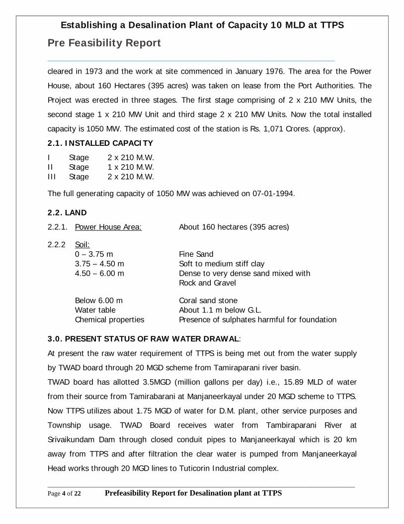
cleared in 1973 and the work at site commenced in January 1976. The area for the Power
House, about 160 Hectares (395 acres) was taken on lease from the Port Authorities. The
Project was erected in three stages. The first stage comprising of 2 x 210 MW Units, the
second stage 1 x 210 MW Unit and third stage 2 x 210 MW Units. Now the total installed
capacity is 1050 MW. The estimated cost of the station is Rs. 1,071 Crores. (approx).
2.1. INSTALLED CAPACITY
I Stage 2 x 210 M.W.II Stage 1 x 210 M.W.III Stage 2 x 210 M.W.
The full generating capacity of 1050 MW was achieved on 07-01-1994.
2.2. LAND
2.2.1. Power House Area: About 160 hectares (395 acres)
2.2.2 Soil:0 – 3.75 m Fine Sand3.75 – 4.50 m Soft to medium stiff clay4.50 – 6.00 m Dense to very dense sand mixed with
Rock and Gravel
Below 6.00 m Coral sand stoneWater table About 1.1 m below G.L.Chemical properties Presence of sulphates harmful for foundation
3.0. PRESENT STATUS OF RAW WATER DRAWAL:
At present the raw water requirement of TTPS is being met out from the water supply
by TWAD board through 20 MGD scheme from Tamiraparani river basin.
TWAD board has allotted 3.5MGD (million gallons per day) i.e., 15.89 MLD of water
from their source from Tamirabarani at Manjaneerkayal under 20 MGD scheme to TTPS.
Now TTPS utilizes about 1.75 MGD of water for D.M. plant, other service purposes and
Township usage. TWAD Board receives water from Tambiraparani River at
Srivaikundam Dam through closed conduit pipes to Manjaneerkayal which is 20 km
away from TTPS and after filtration the clear water is pumped from Manjaneerkayal
Head works through 20 MGD lines to Tuticorin Industrial complex.

Establishing a Desalination Plant of Capacity 10 MLD at TTPS
Pre Feasibility Report_______________________________________________________________________________________
_____________________________________________________________________________________________Page 5 of 22 Prefeasibility Report for Desalination plant at TTPS
Since Tuticorin Thermal Power Station is located at the tail end of the 20 MGD line, one
booster pump house was provided, near SPIC to supply the required quantity of water
to Power Station. There are four ground level reservoirs at the Power Station.
GLR 1 : capacity 5 MG [22.7 Million Litre]
GLR 2 : capacity 5 MG [22.7 Million Litre]
GLR 3 : capacity 10 MG [45.4 Million Litre]
GLR 4 : capacity 20 MG [90.8 Million Litre]
There are two over head tanks of 0.6 Million Litres capacity each. The ground
level reservoirs can meet the requirements of the power station for about one week.
The water system of the Power Station consists of three grades.
One is DM water used for Boiler and Generator Stator cooling. The other is
filtered water used for Auxiliary cooling water system. The third is service water used
for various purposes like Seal water, Coal wetting, Dust suppression, etc.
4.0. WATER REQUIREMENT FOR THE POWER PLANT:
The water requirement for TTPS is as follows.
D.M. Plant I & II (Boiler) : 100 KL / Hour
Potable water : 5 KL / Hour
Auxiliary CWPH : 25 KL / Hour
Regeneration : 20 KL / Hour
Service water : 180 KL / Hour
Township:
Camp I : 35KL / Hour
Camp II : 35KL / Hour
Total : 400KL / Hour
Total water required per day 24 Hours x 400KL = 9600KL

Establishing a Desalination Plant of Capacity 10 MLD at TTPS
Pre Feasibility Report_______________________________________________________________________________________
_____________________________________________________________________________________________Page 6 of 22 Prefeasibility Report for Desalination plant at TTPS
5.0. LOCATION OF DESALINATION PLANT:
The Proposed Desalination Plant will be located within CRZ (Costal Regulation Zone).
An area of 30,400 Sqm is available in eastern side of Cooling water pump house in
between cooling water channel for unit 1,2 & 3 and northern compound wall. This area
is sufficient for the proposed Desalination plant.
The following are the Latitude and longitude of the four corners of the proposed location.
Latitude Longitude
North West Corner: 80 45’ 56.3” N 780 10’ 50.9” E
North East Corner : 80 45’ 52.4” N 780 11’ 02.0” E
South East Corner: 80 45’ 50.5” N 780 11’ 01.9” E
South West Corner: 80 45’ 52.3” N 780 10’ 50.1” E
6.0 INTAKE LOCATION OF SEA WATER:
It is proposed to draw sea water for this Desalination Plant from cooling water pump
house-I. Sufficient sea water is available at CWPH-I in addition to the requirement for
unit I, II and III.
The inflow at CWPH-I is about 1, 25,000 m3 per hour
Water used for cooling purpose for unit I, II and III is about 94,500 m3 per hour.
Water requirement for this Desalination Plant is about 1,250 m3 per hour.
7.0 OUTFALL LOCATION OF BRINE
It is proposed to dispose the brines at outfall arrangements for unit I, II & III. About
90,000 m3 per hour of sea water is being let-out from unit I, II & III through the outfall
structure. The brines disposal from this Desalination Plant is about 833.33 m3 per hour.
8.0 MODE OF CONVEYENCE OF SEA WATER AND BRINE
It is proposed to convey the sea water from cooling water pump house-I to this
Desalination Plant by buried pipe line. The pipe line may be HDPE pipe of size 630mm
outer dia. The brine disposal will also through buried pipe line of size 450mm outer dia
HDPE pipe. For conveying raw water produced from this Desalination Plant to GLRs, it is
proposed use 300mm dia MS ERW pipe.
Establishing a Desalination Plant of Capacity 10 MLD at TTPS
Pre Feasibility Report_______________________________________________________________________________________
_____________________________________________________________________________________________Page 7 of 22 Prefeasibility Report for Desalination plant at TTPS
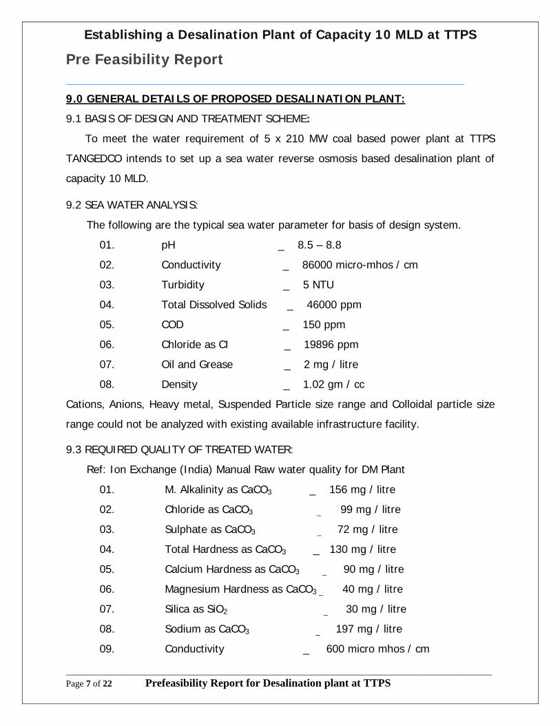
9.0 GENERAL DETAILS OF PROPOSED DESALINATION PLANT:
9.1 BASIS OF DESIGN AND TREATMENT SCHEME:
To meet the water requirement of 5 x 210 MW coal based power plant at TTPS
TANGEDCO intends to set up a sea water reverse osmosis based desalination plant of
capacity 10 MLD.
9.2 SEA WATER ANALYSIS:
The following are the typical sea water parameter for basis of design system.
01. pH _ 8.5 – 8.8
02. Conductivity _ 86000 micro-mhos / cm
03. Turbidity _ 5 NTU
04. Total Dissolved Solids _ 46000 ppm
05. COD _ 150 ppm
06. Chloride as CI _ 19896 ppm
07. Oil and Grease _ 2 mg / litre
08. Density _ 1.02 gm / cc
Cations, Anions, Heavy metal, Suspended Particle size range and Colloidal particle size
range could not be analyzed with existing available infrastructure facility.
9.3 REQUIRED QUALITY OF TREATED WATER:
Ref: Ion Exchange (India) Manual Raw water quality for DM Plant
01. M. Alkalinity as CaCO3 _ 156 mg / litre
02. Chloride as CaCO3 _ 99 mg / litre
03. Sulphate as CaCO3 _ 72 mg / litre
04. Total Hardness as CaCO3 _ 130 mg / litre
05. Calcium Hardness as CaCO3 _ 90 mg / litre
06. Magnesium Hardness as CaCO3 _ 40 mg / litre
07. Silica as SiO2 _ 30 mg / litre
08. Sodium as CaCO3 _ 197 mg / litre
09. Conductivity _ 600 micro mhos / cm

Establishing a Desalination Plant of Capacity 10 MLD at TTPS
Pre Feasibility Report_______________________________________________________________________________________
_____________________________________________________________________________________________Page 8 of 22 Prefeasibility Report for Desalination plant at TTPS
10.0 TREATMENT SCHEME AND OPERATION DATA:
10.1 WATER TREATMENT PLANT:
PRE – TREATMENT FOR DESALINATION PLANT:
The sea water shall be treated through the following Treatment Stages.
S.No Description
1. Flow Control Station
2. Stilling chamber – NaOCl dosage from ECP to remove Algae.
3. Flash mixer – Fecl3 coagulant dosage to remove turbidity.
4. Floccullator–coagulant aid–poly electrolyte dosage to remove colloidal silica
5. Clarifier
6. Pressure sand filter.
7. Filter water storage.
8. Electro chlorination
9. Hypo Degassing
10. Ultra filtration skid (UF)
11. UF permeate cum back wash
12. First pass R.O
13. Potable water storage
10.2 OPERATING DATA OF PRE – TREATMENT SYSTEM:
S.No Description Unit
1. Nos. of units offered 2 Nos
2. Output Capacity of each unit 580 m3 / hour 33. Operating Hours 24 Hrs
Establishing a Desalination Plant of Capacity 10 MLD at TTPS
Pre Feasibility Report_______________________________________________________________________________________
_____________________________________________________________________________________________Page 9 of 22 Prefeasibility Report for Desalination plant at TTPS
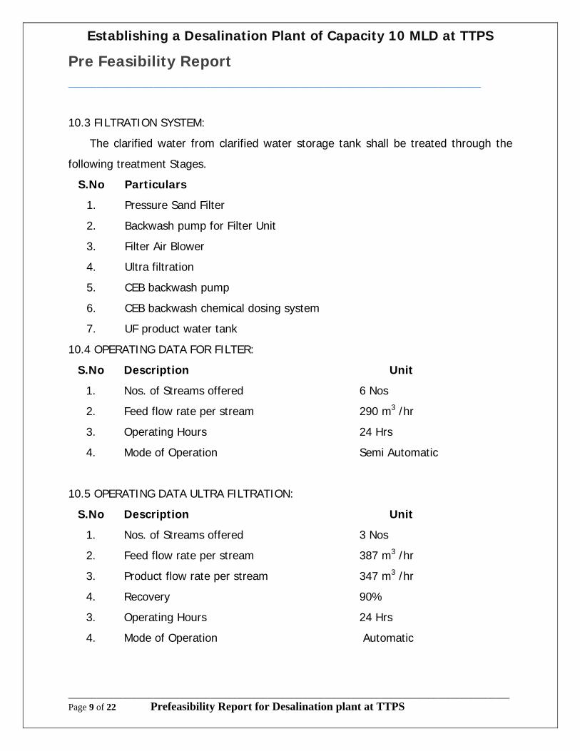
10.3 FILTRATION SYSTEM:
The clarified water from clarified water storage tank shall be treated through the
following treatment Stages.
S.No Particulars
1. Pressure Sand Filter
2. Backwash pump for Filter Unit
3. Filter Air Blower
4. Ultra filtration
5. CEB backwash pump
6. CEB backwash chemical dosing system
7. UF product water tank
10.4 OPERATING DATA FOR FILTER:
S.No Description Unit
1. Nos. of Streams offered 6 Nos
2. Feed flow rate per stream 290 m3 /hr
3. Operating Hours 24 Hrs
4. Mode of Operation Semi Automatic
10.5 OPERATING DATA ULTRA FILTRATION:
S.No Description Unit
1. Nos. of Streams offered 3 Nos
2. Feed flow rate per stream 387 m3 /hr
3. Product flow rate per stream 347 m3 /hr
4. Recovery 90%
3. Operating Hours 24 Hrs
4. Mode of Operation Automatic
Establishing a Desalination Plant of Capacity 10 MLD at TTPS
Pre Feasibility Report_______________________________________________________________________________________
_____________________________________________________________________________________________Page 10 of 22 Prefeasibility Report for Desalination plant at TTPS
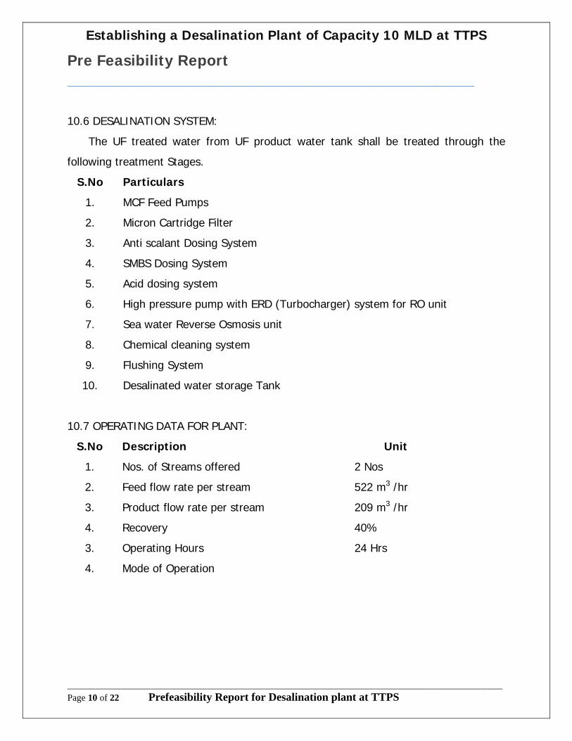
10.6 DESALINATION SYSTEM:
The UF treated water from UF product water tank shall be treated through the
following treatment Stages.
S.No Particulars
1. MCF Feed Pumps
2. Micron Cartridge Filter
3. Anti scalant Dosing System
4. SMBS Dosing System
5. Acid dosing system
6. High pressure pump with ERD (Turbocharger) system for RO unit
7. Sea water Reverse Osmosis unit
8. Chemical cleaning system
9. Flushing System
10. Desalinated water storage Tank
10.7 OPERATING DATA FOR PLANT:
S.No Description Unit
1. Nos. of Streams offered 2 Nos
2. Feed flow rate per stream 522 m3 /hr
3. Product flow rate per stream 209 m3 /hr
4. Recovery 40%
3. Operating Hours 24 Hrs
4. Mode of Operation
Establishing a Desalination Plant of Capacity 10 MLD at TTPS
Pre Feasibility Report_______________________________________________________________________________________
_____________________________________________________________________________________________Page 11 of 22 Prefeasibility Report for Desalination plant at TTPS
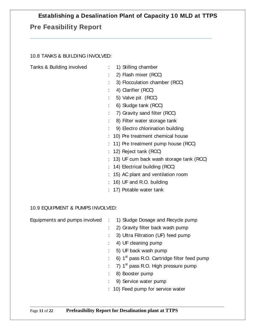
10.8 TANKS & BUILDING INVOLVED:
Tanks & Building involved : 1) Stilling chamber
: 2) Flash mixer (RCC)
: 3) Flocculation chamber (RCC)
: 4) Clarifier (RCC)
: 5) Valve pit (RCC)
: 6) Sludge tank (RCC)
: 7) Gravity sand filter (RCC)
: 8) Filter water storage tank
: 9) Electro chlorination building
: 10) Pre treatment chemical house
: 11) Pre treatment pump house (RCC)
: 12) Reject tank (RCC)
: 13) UF cum back wash storage tank (RCC)
: 14) Electrical building (RCC)
: 15) AC plant and ventilation room
: 16) UF and R.O. building
: 17) Potable water tank
10.9 EQUIPMENT & PUMPS INVOLVED:
Equipments and pumps involved : 1) Sludge Dosage and Recycle pump
: 2) Gravity filter back wash pump
: 3) Ultra Filtration (UF) feed pump
: 4) UF cleaning pump
: 5) UF back wash pump
: 6) 1st pass R.O. Cartridge filter feed pump
: 7) 1st pass R.O. High pressure pump
: 8) Booster pump
: 9) Service water pump
: 10) Feed pump for service water
Establishing a Desalination Plant of Capacity 10 MLD at TTPS
Pre Feasibility Report_______________________________________________________________________________________
_____________________________________________________________________________________________Page 12 of 22 Prefeasibility Report for Desalination plant at TTPS
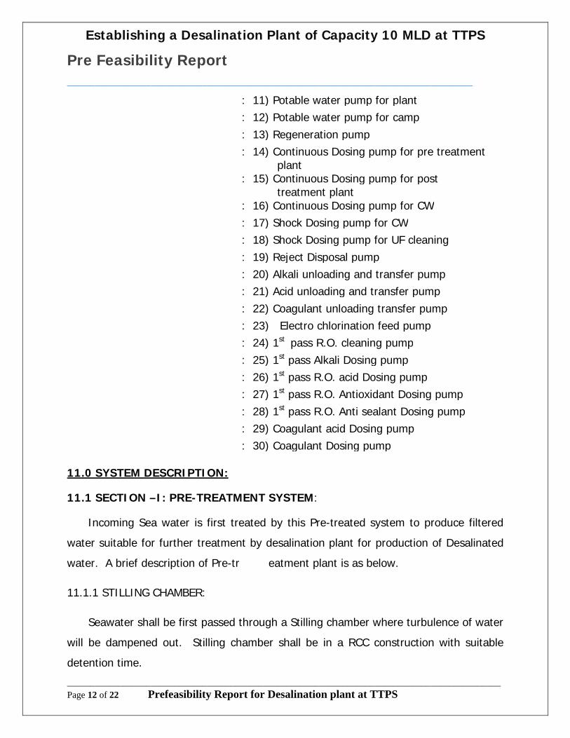
: 11) Potable water pump for plant
: 12) Potable water pump for camp
: 13) Regeneration pump
: 14) Continuous Dosing pump for pre treatment plant
: 15) Continuous Dosing pump for post treatment plant
: 16) Continuous Dosing pump for CW
: 17) Shock Dosing pump for CW
: 18) Shock Dosing pump for UF cleaning
: 19) Reject Disposal pump
: 20) Alkali unloading and transfer pump
: 21) Acid unloading and transfer pump
: 22) Coagulant unloading transfer pump
: 23) Electro chlorination feed pump
: 24) 1st pass R.O. cleaning pump
: 25) 1st pass Alkali Dosing pump
: 26) 1st pass R.O. acid Dosing pump
: 27) 1st pass R.O. Antioxidant Dosing pump
: 28) 1st pass R.O. Anti sealant Dosing pump
: 29) Coagulant acid Dosing pump
: 30) Coagulant Dosing pump
11.0 SYSTEM DESCRIPTION:
11.1 SECTION –I: PRE-TREATMENT SYSTEM:
Incoming Sea water is first treated by this Pre-treated system to produce filtered
water suitable for further treatment by desalination plant for production of Desalinated
water. A brief description of Pre-tr eatment plant is as below.
11.1.1 STILLING CHAMBER:
Seawater shall be first passed through a Stilling chamber where turbulence of water
will be dampened out. Stilling chamber shall be in a RCC construction with suitable
detention time.

Establishing a Desalination Plant of Capacity 10 MLD at TTPS
Pre Feasibility Report_______________________________________________________________________________________
_____________________________________________________________________________________________Page 13 of 22 Prefeasibility Report for Desalination plant at TTPS
11.1.2 FLASH MIXER:
Flash mixers are specially designed for the process requirement in the water and
wastewater treatment. The mixer design ensures efficient, minimum energy
consumption and long life. This equipment blends coagulants and other chemicals with
water / wastewater prior to flocculation. The aggressive agitation results in
instantaneous and effective mixing of chemicals. This unit is also useful for general
mixing.
11.1.3 DUAL MEDIA SAND FILTERS:
Filtered water from clarifier shall be further filtered by dual media sand filter unit in
order to remove suspended matters of turbidity present in water.
11.1.4. FILTER BACHWASH SYSTEM:
The water required for backwashing of Pressure Sand Filter is supplied from RO reject water tank.
11.1.5 AIR SCOURING BLOWER FOR FILTERS:
Low pressure high flow air is supplied to media filter (PSF) with the help of this
filter air blower for loosening of filter bed during backwashing. Each blower is fitted with
suction air filter, discharge pipe work, Non return valve, isolation valves & Pressure
gauge at discharge.
11.1.6 SLUDGE PIT:
Sludge generated by clarifier is collected in the sludge pit which shall be then
transferred to ash pond through sludge disposal pumps.
11.1.7 ULTRA FILRATION:
Ultra filtration (UF) is a variety of membrane filtration in which hydrostatic
pressure forces a liquid against a semi permeable membrane. Suspended solids and
solutes of high molecular weight are retained, while water and low molecular weight
Establishing a Desalination Plant of Capacity 10 MLD at TTPS
Pre Feasibility Report_______________________________________________________________________________________
_____________________________________________________________________________________________Page 14 of 22 Prefeasibility Report for Desalination plant at TTPS
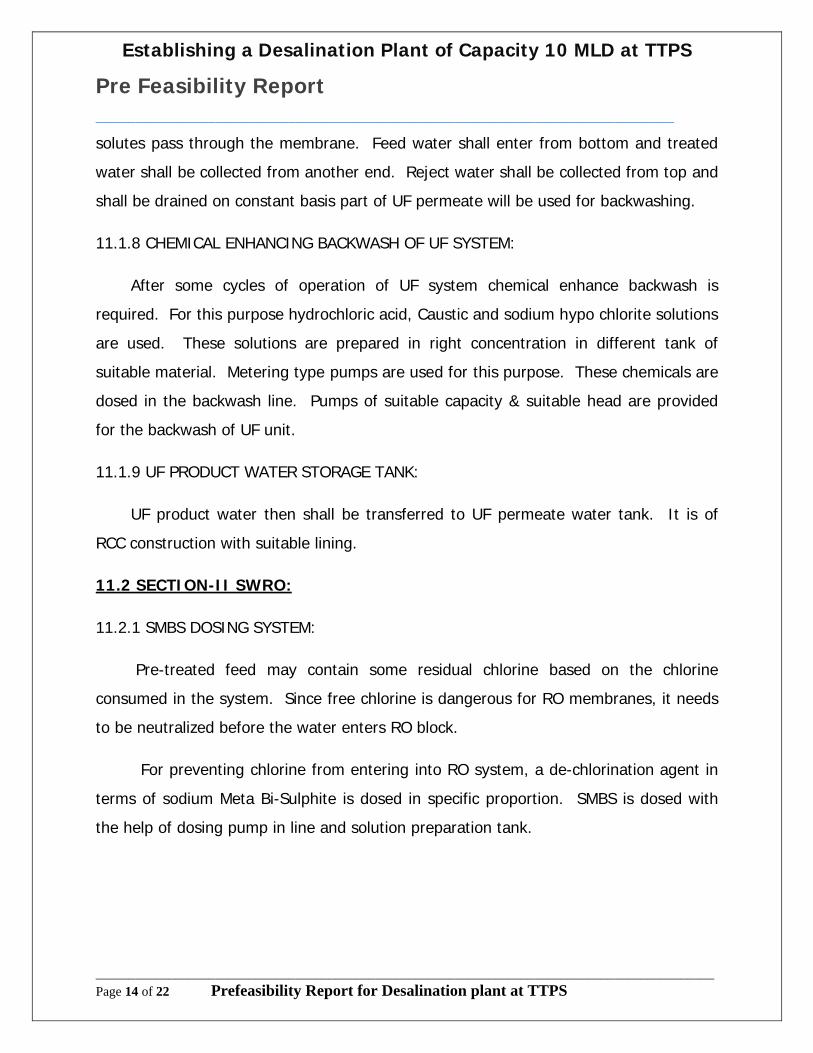
solutes pass through the membrane. Feed water shall enter from bottom and treated
water shall be collected from another end. Reject water shall be collected from top and
shall be drained on constant basis part of UF permeate will be used for backwashing.
11.1.8 CHEMICAL ENHANCING BACKWASH OF UF SYSTEM:
After some cycles of operation of UF system chemical enhance backwash is
required. For this purpose hydrochloric acid, Caustic and sodium hypo chlorite solutions
are used. These solutions are prepared in right concentration in different tank of
suitable material. Metering type pumps are used for this purpose. These chemicals are
dosed in the backwash line. Pumps of suitable capacity & suitable head are provided
for the backwash of UF unit.
11.1.9 UF PRODUCT WATER STORAGE TANK:
UF product water then shall be transferred to UF permeate water tank. It is of
RCC construction with suitable lining.
11.2 SECTION-II SWRO:
11.2.1 SMBS DOSING SYSTEM:
Pre-treated feed may contain some residual chlorine based on the chlorine
consumed in the system. Since free chlorine is dangerous for RO membranes, it needs
to be neutralized before the water enters RO block.
For preventing chlorine from entering into RO system, a de-chlorination agent in
terms of sodium Meta Bi-Sulphite is dosed in specific proportion. SMBS is dosed with
the help of dosing pump in line and solution preparation tank.

Establishing a Desalination Plant of Capacity 10 MLD at TTPS
Pre Feasibility Report_______________________________________________________________________________________
_____________________________________________________________________________________________Page 15 of 22 Prefeasibility Report for Desalination plant at TTPS
11.2.2 ANTI-SCALANT DOSING SYSTEM:
During Reverse Osmosis process, dissolved salts are concentrated reject side as
permeate water is being drawn at a specific recovery. As a result of this, dissolved salts
concentration increases on reject end and may precipitate if saturation limit exceeds.
As a resultant effect of salt concentration, scaling (deposition) occurs on membrane
surface which results in reduced flow rate and increased pressure requirement in RO
system. For prevention of scaling and anti scalent formulation is closed in specific
proportion. For anti scalent closing purpose closing pumps and solution preparation
tanks are provides.
11.2.3 ACID DOSING SYSTEM:
Since raw water analysis indicates wide range for pH, provision for acid dosing
system has been provided as an additional safety for prevention of scale formation on
RO membranes.
For acid dosing purpose dosing pumps and solution preparation tanks are
provided.
11.2.4 MICRON CARTRIDGE FILTER:
After chemical dosing, RO feed water may get contaminated with very fine
suspended matters. To supply highly filtered water micron cartridge filter units are
provided in parallel operation. Each MCF unit is a vertical pressure vessel. Internally it
is fitted with PP wound depth type micron cartridge filter element. Water to be filtered
passed though this cartridge element to produce highly filtered RO feed water.
11.2.5 HIGH PRESSURE PUMP (WITH ENERGY RECOVERY DEVICE): Multi stage
Horizontal centrifugal type of High pressure pump with energy recovery device shall be
provided for supply of high pressure filtered water to RO system.

Establishing a Desalination Plant of Capacity 10 MLD at TTPS
Pre Feasibility Report_______________________________________________________________________________________
_____________________________________________________________________________________________Page 16 of 22 Prefeasibility Report for Desalination plant at TTPS
Each pump shall be fitted with super duplex piping (high pressure side) and same
material of construction for pump. Necessary instruments & isolation valves are
provided for necessary control of system. An energy recovery device (Turbocharger) is
used to recover significant energy available in RO brine stream there by reducing the
pumping cost.
11.2.6 ENERGY RECOVERY DEVICE:
Turbocharger is a unique energy recovery turbo pump designed specifically for
reverse osmosis service. The Turbo provides a direct pressure boost to the RO feed
stream from energy recovered from the brine stream. This pressure transfer is
accomplished in a single casing design utilizing a rotor on which turbine and pump
impellers are mounted on the same shaft.
High-pressure brine from the RO membranes enters the turbine volute
tangentially through a titanium nozzle where the brine pressure energy is partially
converted to a high velocity flow. This flow then enters a Francis type reaction turbine
where additional fluid energy is converted to shaft work. The mechanical shaft energy
produced by the turbine is converted back to pressure energy by the pump impeller.
11.2.7 REVERSE OSMOSIS SYSTEM:
Sea water RO system is provided for removal of salinity from feed sea water. RO
system comprises of spirally wound Seawater RO membranes, housed in FRP Pressure
tubes.
RO pressure tubes shall be mounted horizontally on Mild Steel Structural
fabricated/Epoxy painted RO Skid. For each stream, a feed, product and reject header
with End ports connection and victaulic coupling are provided for easy maintenance.
For monitoring of various parameters like pressure, flow, & conductivity,
respective field mounted indicators/micro processors based analyzing instruments are

Establishing a Desalination Plant of Capacity 10 MLD at TTPS
Pre Feasibility Report_______________________________________________________________________________________
_____________________________________________________________________________________________Page 17 of 22 Prefeasibility Report for Desalination plant at TTPS
provided at required location. An electrical & instrumentation panel with PLC control is
provided for semi automatic operation of RO system. Product water from each RO
system is finally collected & stored in permeate water storage tank.
11.2.8 SUCK BACK TANK:
Each RO skid is provide with suck back tank arrangement. The main motive
behind providing this provision is to ensure that RO system is protected from any back
pressure, deposition of salinity during the shutdown of the RO system.
11.2.9 DESALINATED WATER STORAGE TANK:
Permeate water is stored in a permeate water storage tank.
11.2.10 CHEMICAL CLEANING SYSTEM & RO FLUSHING SYSTEM:
This system comprises of a Chemical solution preparation tank, a micron cartridge filter
unit chemical cleaning pump & flexible hoses Cleaning of membrane is carried out at a
regular duration for removal of any deposition of organic salts, suspended matters,
Microbiological impurities on membrane surface over a continuous period of usage. The
Cleaning chemical is passed in the same direction as that of feed water flow in order to
remove the deposition from membranes. Prescribed chemical solution of required
concentration is prepared in tank. It is re-circulated with the help of chemical cleaning
pump and micron cartridge filter through RO system at specified flow rate and pressure
after primary flushing with permeate water. After cleaning, permeate shall be used for
RO system flushing and final cleaning.
11.2.11 BRINE WATER TANK AND TRANSFER PUMPS:
Reject from PSF backwash water and UF reject water and from SWRO system
shall be collected in this tank. This will be disposed off to the sea in the cooling water
outfall of units I,II and III.

Establishing a Desalination Plant of Capacity 10 MLD at TTPS
Pre Feasibility Report_______________________________________________________________________________________
_____________________________________________________________________________________________Page 18 of 22 Prefeasibility Report for Desalination plant at TTPS
12.0 EQUIPMENTS INVOLVED IN DESALINATION PLANT:
S.No Description Quantity
1. Flow control station 1 No
2. Electro chlorination system 1 No
3. Stilling chamber (1 min retention time) 1 No
4. Coagulant dosing arrangement 2 Nos.
5. Flash mixer (1min retention time) 2 Nos.
6. Agitator for flash mixer 2 Nos.
7. Flocculator (1min retention time) 2 Nos.
8. Agitator for Flocculator 4 Nos.
9. Clarifier 2 Nos.
10. Media for Clarifier 2 Nos.
11. Isolation gates for Pre-treatment system 4 Nos.
12. Sludge pit (4 hours retention) 1 No
13. Sludge disposal pump 2 Nos. (1W +1S)
14. Air blower for sludge pit 2 Nos. (1W + 1S)
15. Air grid arrangement for sludge pit 1 Lot
16. Fecl3 bulk storage tank 2 Nos.
17. Fecl3 unloading pump 2 Nos. (1W + 1S)
18. Fecl3 dosing tank 2 Nos.
19. Agitator for Fecl3 dosing tank 2 Nos.
20. Fecl3 dosing pump 4 Nos. (2W + 2S)
21. PE dosing tank 2Nos.
22. Agitator for PE dosing tank 2 Nos.
23. PE dosing pump 4 Nos. (2W + 2S)
24. PT service water preparation tank 1 No
25. PT chemical storage building (2 storeyed) 1 No

Establishing a Desalination Plant of Capacity 10 MLD at TTPS
Pre Feasibility Report_______________________________________________________________________________________
_____________________________________________________________________________________________Page 19 of 22 Prefeasibility Report for Desalination plant at TTPS
26. Electrical hoist for chemical building 1 No
27. Weighing scale for chemical building 1 No
28. Clarified water storage tank-2 compartment
(4 hrs retention)
1 No
29. Filter feed pump 5 Nos. (4W + 1S)
30. Pressure sand filter 5 Nos. (4W + 1S)
31. Media for PSF 1 Lot
32. Filter backwash pump 2 Nos. (1W +1S)
33. Air blower for filter backwash pump 2 Nos. (1W +1S)
34. Basket strainer for UF 3 Nos.
35. UF skid 3 Nos.
36. UF membranes 1 Lot
37. UF backwash pump 3 Nos. (2W +1S)
38. Acid dosing tank for CEB 2 Nos.
39. Acid dosing pump 2 Nos.
40. Alkali dosing tank for CEB 2 Nos.
41. Alkali dosing pump 2 Nos.
42. NaoCl dosing tank for CEB 2 Nos.
43. NaoCl dosing pump 2 Nos.
44. UF product cum backwash water storage tank 1 No
45. SWRO feed pump 3 Nos. (2W +1S)
46. Acid dosing tank 4 Nos.
47. Acid dosing pump 3 Nos. (2W +1S)
48. Antiscalant dosing tank 4 Nos.
49. Agitator for antiscalant dosing tank 4 Nos.
50. Antiscalant dosing pump 3 Nos. (2W +1S)
51. SMBS dosing tank 4 Nos.

Establishing a Desalination Plant of Capacity 10 MLD at TTPS
Pre Feasibility Report_______________________________________________________________________________________
_____________________________________________________________________________________________Page 20 of 22 Prefeasibility Report for Desalination plant at TTPS
52. Agitator for SMBS dosing tank 4 Nos.
53. SMBS dosing pump 3 Nos. (2W +1S)
54. Micron cartridge filter 3 Nos. (2W +1S)
55. Cartridges for MCF 1 Lot
56. SWRO high pressure pumps (Turbocharger) 3 Nos. (2W +1Store)
57. Turbocharger 2 Nos. (2W +0S)
58. SWRO skids 2 Nos.
59. SWRO membranes 1 Lot
60. SWRO pressure tubes 1 Lot
61. Suck back tank 2 Nos.
62. Desalinated water cum fire water storage tank 1 No
63. RO CIP tank 1 No
64. RO CIP pump 2 Nos. (1W +1S)
65. Cartridge filter for RO CIP 1 No
66. SWRO flushing pump 2 Nos. (1W +1S)
67. Reject / Brine water tank 1 No
68. Miscellaneous
69. Safety shower 1 Lot
70. Dissolving basket 1 Lot
71. Interconnecting piping 1 Lot
72. Access ladder, walkway and handrials 1 Lot
13.0. COST OF THE PROJECT
The project cost for the proposed Desalination plant of capacity 10 MLD is arrived at
based on the estimated unit cost which includes all machineries, erection charges, civil
works etc., and includes the cost towards interest during construction. A brief summary
is given below

Establishing a Desalination Plant of Capacity 10 MLD at TTPS
Pre Feasibility Report_______________________________________________________________________________________
_____________________________________________________________________________________________Page 21 of 22 Prefeasibility Report for Desalination plant at TTPS
13.1. CAPITAL COST
Sl.No Particulars Amount1 Land lease rent & development
30400 sq.m x 36.00x10 1,09,44,000
2 Environment Impact Assessment study, Environment Management plan, DPR, Obtaining mandatory clearances etc.,
50,00,000
3 Design, Engineering, supply of equipments and components for SWRO plant, erection and commissioning
51,10,00,000
4 Approximate cost for spares for 2 years 3,14,00,0004 Cost for Intake and Brine disposal system 17,44,00,0005 Interest during construction
73,27,44,000 x 22/100 16,12,03,680
Total project cost 89,39,47,680
13.2. WORKING CAPITAL (FOR 5 YEARS)
Description Value (Rs.)
Operation and Maintenance cost 19,66,00,000
Cost of consumables and chemicals 7,50,00,000
Cost of consumption of O&M power 16,50,00,000
Total 43,66,00,000
13.3. TOTAL CAPITAL INVESTMENT
Fixed Capital 89,39,47,680
Working Capital per year = 43,66,00,000/5 8,73,20,000
Total 98,12,67,680

Establishing a Desalination Plant of Capacity 10 MLD at TTPS
Pre Feasibility Report_______________________________________________________________________________________
_____________________________________________________________________________________________Page 22 of 22 Prefeasibility Report for Desalination plant at TTPS
14. FINANCIAL ANALYSIS
14.1. COST OF PRODUCTION (PER YEAR)
Cost of Production (per year) (Rs.)
Total Recurring Cost 8,73,20,000
Interest on Total Capital Investment @ 22% (98,12,67,680 x 22/100) 21,58,78,889.6
Total 30,31,98,889.6
14.2. TURNOVER (FOR 1 YEAR)
Qty per year Cost per KL
3650000 KL water 30,31,98,889.6/3650000 = 83.06
15. Conclusion
The proposed desalination plant will cater the raw water requirement of TTPS. The present requirement of 10 MLD water is supplied by the TWAD Board.
By establishing the new Desalination plant, the water supplied by the civic body could well be utilized for the domestic usage.