Embed Size (px)
Citation preview

Tamagotchis N e e d N o t Die - Verification of STATEMATE Des igns
Udo Brockmeyer and Gunnar Wittich *
OFFIS, Escherweg 2, 26121 Oldenburg, Germany emaih {Brockmeyer,Wittich}@OFFIS.Uni-Oldenburg.de
Abs t rac t . This paper presents a toolset we built for supporting verification of STATEMATE 1 designs. STATEMATE is a widely used design tool for embedded control applications. Designs are translated into finite state machines which are optimized and then verified by symbolic model checking. To express requirement specifications the visual formalism of symbolic timing diagrams is used. Their semantics is given by translation into temporal logic. If the model checker generates a counterexample, it is retranslated into either a symbolic timing diagram or a stimulus for the STATEMATE simulator.
1 I n t r o d u c t i o n
Growing complexity and wide usage of embedded systems in safety critical applications raises the demand for proving their correctness. Because verification with theorem provers [16] is a difficult task even for experts, automatic verification techniques, in particular model checking [3, 4], are gaining increasing influence in the development of industrial applications.
In this paper we present a toolset we built for the verification of STATEMATE designs [11, 12, 14]. STATEMATE is a widely used graphical specification tool for embedded control applications. The STATEMATE toolset captures the phases of specification, analysis, design and documentation of real-time embedded systems. To cope with the complexity of real life applications, a system under development (SUD) may be described graphically from three different viewpoints within STATEMATE. They cover the structural (Module-Charts), the functional (Activity-Charts) and the behavioral (Statecharts [10]) aspects of a SUD.
For the verification of STATEMATE designs we use the technique of model checking. Model checking is an automatic method for proving that a given implementation of a design meets its requirement specification represented by a temporal logic formula. To be able to verify STATEMATE designs, we have implemented a set of tools for the translation from STATEMATE into finite state machines required by the model checker [9, 19]. The semantical foundation
* Part of this work has been funded by the Commission of the European Communities under the ESPRIT project 20897, SACRES and the German BMBF project KORSYS, grant number 01-IS-519-E-O
1 STATEMATE is a registered trademark of i-Logix Inc.
218
of this translation can be found in [6]. In our environment we use symbolic timing diagrams [7, 18] for the specification of the intended behavior. Symbolic timing diagrams are a graphical specification formalism. The semantics of these diagrams can be expressed by CTL formulae [17] that are fed into the model checker.
If a design does not meet the requirement specification the model checker generates a counterexample. For debugging purposes this counterexample can be retranslated into a timing diagram and also into a stimulus for the STATEMATE simulator. This visualization of a counterexample is a convenient way to point out the error to the designer.
A work that is closely related to our work can be found in [15]. There a formal semantics for a subset of Statecharts is given which is based on the basic step algorithm as defined in [12]. Also an experimental compiler for connecting a model checker is presented. Our environment supports the synchronous (step) semantics as well as the so called asynchronous (super-step) semantics provided by the STATEMATE simulator and therefore both of the semantics given in [12]. In addition to almost the complete language of Statecharts, including timing aspects, the language of Activity-Charts is covered by our toolset.
As a sample application for the demonstration of our verification environment we have implemented a simplified version of a tamagotchi. With our environment we have proved some interesting properties e.g. the possibility of keeping the tamagotchi alive. Beside this toy example industrial sized applications have been verified with our toolset. Examples for these applications are a central car locking mechanism, provided by our project partner BMW [5], and a aircraft storage management system, provided by our project partner British Aerospace.
This paper is organized as follows. In section 2 we shortly describe symbolic timing diagrams as a visual specification formalism by giving two examples. Section 3 overviews STATEMATE and clarifies its concepts. In section 4 we introduce our sample application. The fifth section covers our verification environment. In section 6 we give some experimental results. Section 7 concludes this paper with an outlook on our future work.
2 Specification with Symbolic Timing Diagrams
In our verification environment symbolic timing diagrams (STD) are used to specify graphically the requirements of reactive systems. STD have a well- defined semantics given by translation into temporal logic. Thus, they are a user-friendly notation with a formal semantics to express the properties that have to be verified. A more detailed description of STD is given in [7, 17, 18].
An advantage of STD is that they are declarative, allowing a designer to specify requirements incrementally. The complete specification is then given as a conjunction of the different STD. When using STD as described above, requirements of reactive systems are described in a compact form. Also, by composing several STD, very complex requirements can be specified in a modular way.
219
We clarify the concepts by giving two simple but relevant STD specifications for our sample application tamagotchi. The first requirement states that our tamagotchi will always die in the future. We expect this specification not to be valid over the model, inducing the model checker to generate a counterexample. This counterexample is a path on which the tamagotchi never dies. The second requirement says that our tamagotchi will never die. Again, we expect a counterexample for this diagram, giving a path on which the tamagotchi finally dies.
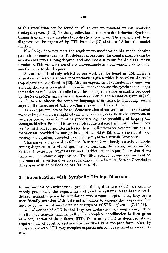
Fig. 1. The STD for property 1
Figure 1 shows the STD for the first property. Every STD describes allowed valuations of visible interface objects of a design over time. The graphical description of every property consists of three parts. On the left side in figure 1 the interface variables which are constrained by an STD are listed together with their data-types. In figure 1, we have just one variable DEAD of type BOOLEAN. An STD consists of symbolic waveforms representing the valuation of interface variables over time. Different phases of the waveforms are annotated with predicates over these variables. Waveforms are worked off from the left side to the right. The valuation of interface variables and thus of predicates is influenced by the dynamic behavior of a design. If a predicate changes from TRUE to FALSE, the next predicate on the right side must evaluate to TRUE. Otherwise, the STD is violated. The conjunction of the predicates in every first phase gives the activation condition of an STD. In figure 1 we have the activation condition that DEAD equals FALSE. The activation mode of an STD is either "initial", meaning it must hold in the initial state of the design, or "invariant", meaning it must hold every time the activation condition becomes TRUE. The activation mode for the diagram in figure 1 is "invariant". The arc in the diagram denotes that the predicate DEAD equals TRUE must eventually become TRUE, thus specifying a liveness property. The informal semantics of this diagram is that whenever DEAD equals FALSE a state will be reached where DEAD equals TRUE.
220
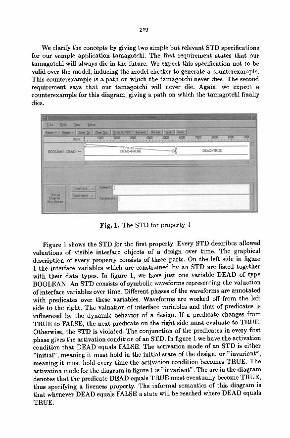
Figure 2 shows the STD for the second property. This time the only waveform is the one for the BOOLEAN variable ALIVE. The waveform of this "invariant" STD constraints the valuation of ALIVE over time by three predicates. The activation condition is satisfied when ALIVE evaluates to FALSE. When ALIVE becomes TRUE, the STD "steps" into the next phase. The last predicate FALSE cannot be evaluated to TRUE meaning that the STD can only be fulfilled if ALIVE stays TRUE forever, hence this STD specifies a safety property. The informal semantics of this diagram is that once the tamagotchi is alive, it will stay alive.
Fig. 2. The STD for property 2
3 K e y F e a t u r e s o f STATEMATE
In this section an introduction into key features of STATE;MATE is given. First, the different languages of STATE;MATE are described together with an overview on the available set of tools. In the following subsection interesting points concerning semantical issues are pointed out.
3.1 STATE;MATE Toolset
The STATEMATE; toolset [11,12, 14] captures the phases of specification, analysis, design and documentation of real-time embedded systems. To cope with the complexity of real life applications, a system under development (SUD) may be described graphically from three different viewpoints within STATEMATE;. They cover the structural, the functional and the behavioral aspects of a SUD.
A designer can create a model of a SUD describing physical components and their interconnections within Module-Charts. Activity-Charts specify a SUD as a collection of hierarchically and parallelly composed activities and data- and control-flows between activities. This is the method to model a functional decomposition of a SUD. Activities that are not further refined may be described by Statechavts. Statecharts essentially represent finite state machines enhanced

221
by concepts of hierarchy, orthogonality and a broadcasting mechanism. Inside a Statechart an arbitrary number of state machines can work in parallel. They communicate via a broadcasting mechanism. A state machine can only be active ff and only if its parent is active. Statecharts describe when and how activities in a SUD react to external stimuli. They are intended to implement controller behavior. Designers can use two time concepts in Statecharts. Actions may be scheduled into the future and the reaction on events may be delayed for some amount of time. Within STATEMATE the real-time behavior of a SUD is evaluated relatively to a virtual simulation clock. Several semantics for the above mentioned languages are supported by the tool (see subsection 3.2).
Referenced elements within the three modeling languages have to be defined in a data-dictionary. Three classes of elements exist. Events are instantaneous elements. They live exactly one step before they are consumed. Conditions and data-items retain their values over time. Conditions are the STATEMATE variant of boolean variables. Data-Items can have more complex types like bit, integer and real. Every data-item may also be structured as an array, record, union or as a queue.
Within STATEMATE an interactive analysis can be done on the design with a simulator. A dynamic test tool can be used to check simple properties of the model. Code generators for software and hardware modules are available to produce prototyped code for the model. The remaining tools are for the purposes of documentation, requirement traceability and revision management.
3.2 S e m a n t i c s o f STATEMATE
In the past several semantics for Statecharts have been investigated, for instance [13]. STATEMATE also incorporates several semantics for its languages. We can distinguish between the synchronous simulation semantics or step semantics, the asynchronous simulation semantics or super-step semantics and the semantics of the generated code for C-, ADA-, VHDL- and Verilog. Informal explanations of these semantics can be found in [12]. Our toolset handles the step and the super-step semantics. A rigorous and formal definition can be found in [6].
In the step semantics the SUD accepts an external stimulus to trigger the modeled reactive system. Then all active components of the design perform exactly one step synchronously to come to a new state configuration and a new valuation of variables. Every step costs a fixed amount of t ime for every parallel component. After termination of a step, the SUD accepts new stimuli. The step semantics is mainly used for clocked designs.
The basic idea of the super-step semantics is, that after having given an external stimulus to a SUD being in a stable state, it starts a chain of steps until it reaches a stable state again. Stable means, that further steps are impossible without new external stimuli. A large number of reactions are possible until a stable state is reached again. A complete chain is called a super-step, while every single computat ion is called a step. In contrast to the step semantics, the steps in such a chain do not consume time. All computations between stimulation of such a SUD and returning into a state of equilibrium are performed infinitely

222
fast, hence the virtual simulation clock is not incremented before a super-step has been finished. After completion of a super-step the clock will be advanced to the next relevant point in time. A point in time is relevant, if a scheduled action has to be executed, if a timeout event has expired or if a SUD is triggered again by a new external stimulus. This semantics constraints the interaction of the environment with a SUD to super-step boundaries, but all activities inside a SUD work synchronously and communicate after every step. A prerequisite is, that all activities have completed their actual step. If one activity diverges, e.g. by executing an unbounded loop, then the actual step cannot be terminated and the super-step is unbounded. The super-step semantics is mainly used for asynchronous designs.
This overview shows that the step semantics is much simpler than the super- step semantics. In the step semantics the SUD is stable after every terminated step, time increases uniformly and the environment can influence the valuation of variables on every step. In contrast, the super-step semantics needs additional bookkeeping to indicate stability. Only in a stable state the system can increase timers and can accept new stimuli.
4 A STATEMATE E x a m p l e
In this section the concepts of STATEMATE are clarified by introducing a tamagotchi as a sample application. The STATEMATE design consists mainly of an Activity-Chart and a set of parallel automata that are described by a Statechart. The Activity-Chart defines the environment and the interface of the application, the Statechart controls the state of the system and reacts on environment actions.
Fig. 3. The Activity-Chart for the tamagotchi
The state of the tamagotchi consists of a set of counters. These counters cover the levels for saturation, liquid, wellbeing, fitness and healthiness. The changes of every counter over time are controlled by the above automata. In every
223
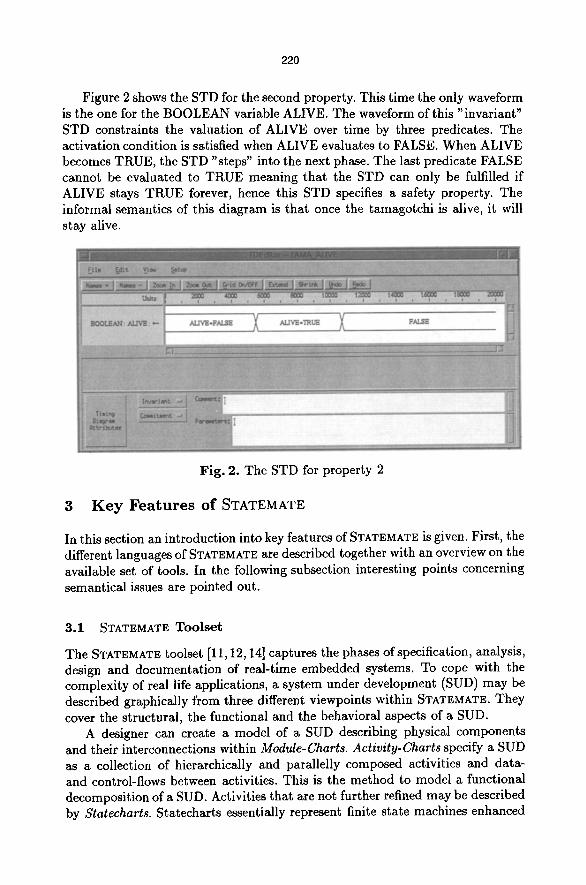
step the counters for saturation, liquid, wellbeing and fitness are decremented by one. The counter for healthiness is decremented depending on the levels for wellbeing and fitness. If the level for wellbeing is zero, the counter for healthiness is decremented by 3; if the level for fitness is zero, it is decremented by 4. If a counter falls below a certain threshold, the tamagotchi outputs a corresponding message. This message is reset when the counter raises again and reaches another threshold. As soon as one of the counters for saturation, liquid or healthiness becomes zero, the tamagotchi dies. To prevent this, the environment (the owner of the tamagotchi) can influence the counters by several actions. In every step one and only one of the actions eat, drink, stroke, play and 'giving an injection' can be performed. These actions increase the corresponding counters by 2,3,15,12 and 7 until upper bounds are reached. The tricky task is that in one step all counters can be decremented, but only one of them can be incremented by an environment action. By interpreting the outputs of the tamagotchi, the next action can be chosen.
Fig. 4. The Statechart for the tamagotchi
224
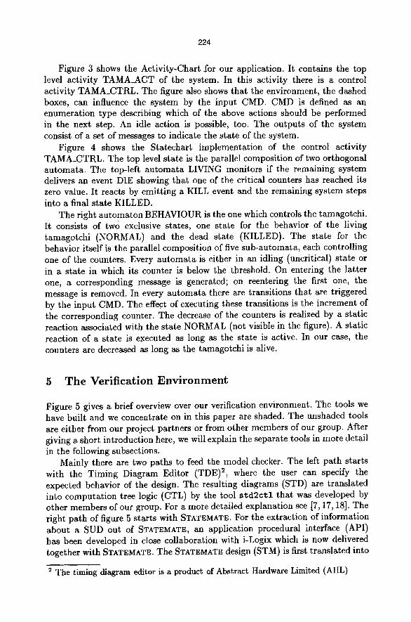
Figure 3 shows the Activity-Chart for our application. It contains the top level activity TAMA_ACT of the system. In this activity there is a control activity TAMA_CTRL. The figure also shows that the environment, the dashed boxes, can influence the system by the input CMD. CMD is defined as an enumeration type describing which of the above actions should be performed in the next step. An idle action is possible, too. The outputs of the system consist of a set of messages to indicate the state of the system.
Figure 4 shows the Statechart implementation of the control activity TAMA_CTRL. The top level state is the parallel composition of two orthogonal automata. The top-left automata LIVING monitors if the remaining system delivers an event DIE showing that one of the critical counters has reached its zero value. It reacts by emitting a KILL event and the remaining system steps into a final state KILLED.
The right automaton BEHAVIOUR is the one which controls the tamagotchi. It consists of two exclusive states, one state for the behavior of the living tamagotchi (NORMAL) and the dead state (KILLED). The state for the behavior itself is the parallel composition of five sub-automata, each controlling one of the counters. Every automata is either in an idling (uncritical) state or in a state in which its counter is below the threshold. On entering the latter one, a corresponding message is generated; on reentering the first one, the message is removed. In every automata there are transitions that are triggered by the input CMD. The effect of executing these transitions is the increment of the corresponding counter. The decrease of the counters is realized by a static reaction associated with the state NORMAL (not visible in the figure). A static reaction of a state is executed as long as the state is active. In our case, the counters are decreased as long as the tamagotchi is alive.
5 The Verification Environment
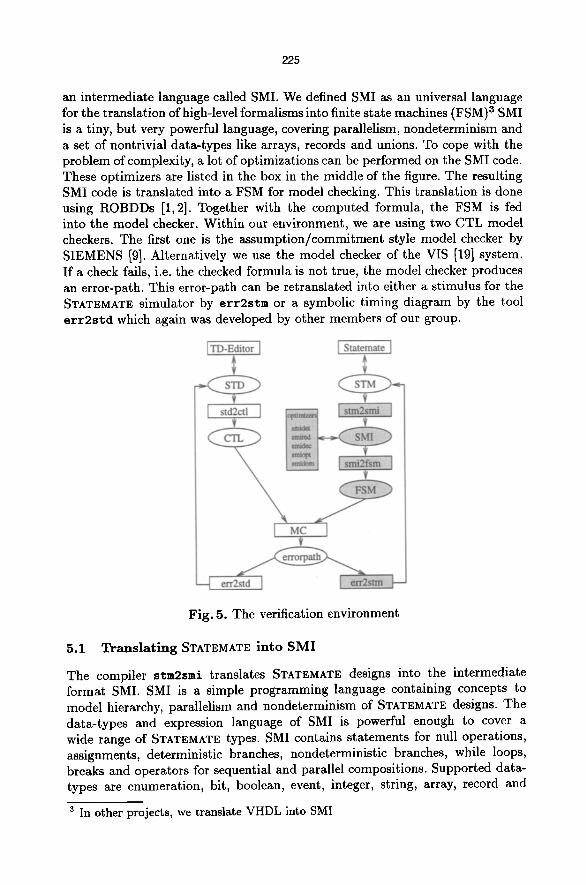
Figure 5 gives a brief overview over our verification environment. The tools we have built and we concentrate on in this paper are shaded. The unshaded tools are either from our project partners or from other members of our group. After giving a short introduction here, we will explain the separate tools in more detail in the following subsections.
Mainly there are two paths to feed the model checker. The left path starts with the Timing Diagram Editor (TDE) 2, where the user can specify the expected behavior of the design. The resulting diagrams (STD) are translated into computat ion tree logic (CTL) by the tool s t d 2 c t l that was developed by other members of our group. For a more detailed explanation see [7, 17, 18]. The right path of figure 5 starts with STATEMATE. For the extraction of information about a SUD out of STATEMATE, an application procedural interface (API) has been developed in close collaboration with i-Logix which is now delivered together with STATEMATE. The STATEMATE design (STM) is first translated into
2 The timing diagram editor is a product of Abstract Hardware Limited (AHL)
225
an intermediate language called SMI. We defined SMI as an universal language for the translation of high-level formalisms into finite state machines (FSM) 3 SMI is a tiny, but very powerful language, covering parallelism, nondeterminism and a set of nontrivial data-types like arrays, records and unions. To cope with the problem of complexity, a lot of optimizations can be performed on the SMI code. These optimizers are listed in the box in the middle of the figure. The resulting SMI code is translated into a FSM for model checking. This translation is done using ROBDDs [1,2]. Together with the computed formula, the FSM is fed into the model checker. Within our environment, we are using two CTL model checkers. The first one is the assumption/commitment style model checker by SIEMENS [9]. Alternatively we use the model checker of the VIS [19] system. If a check fails, i.e. the checked formula is not true, the model checker produces an error-path. This error-path can be retranslated into either a stimulus for the STATEMATE simulator by e r r 2 s t m or a symbolic timing diagram by the tool e r r 2 s t d which again was developed by other members of our group.
Fig. 5. The verification environment
5.1 T r a n s l a t i n g STATEMATE i n t o S M I
The compiler stm2sms translates STATEMATE designs into the intermediate format SMI. SMI is a simple programming language containing concepts to model hierarchy, parallelism and nondeterminism of STATEMATE designs. The data-types and expression language of SMI is powerful enough to cover a wide range of STATEMATE types. SMI contains statements for null operations, assignments, deterministic branches, nondeterministic branches, while loops, breaks and operators for sequential and parallel compositions. Supported data- types are enumeration, bit, boolean, event, integer, string, array, record and
3 In other projects, we translate VHDL into SMI
226
union. The expression language contains common boolean and numeric operators and selection on arrays, records and unions.
In the translation process stm2smi performs several tasks. It maps used data- types of a design onto the types of SMI. In addition the state configurations of the Statecharts are encoded by SMI variables. Therefore, stm2smi defines variables to encode data and boolean variables, events and the control information of a design. With every variable in SMI we keep some additional information for back-annotation including the original name, its data-type, its mode (in, out, local) and its origin in a design (data, condition, event, timer, control). These information are mainly used if the model checker produces a counterexample for a given property.
In [6] a compositional semantics for STATEMhTE is given. This means, that the semantics of a model contains all possible behaviors of its environment. For the generation of compositional models, some additional variables are introduced. These variables indicate stability and divergence of the model and its environment.
In STATEMATE, all active activities perform a step synchronously, then new stimuli are accepted and the next step is executed. To represent the cyclic behavior of a reactive system modeled as a STATEMATE design, we embed the generated code for a design in a never terminating while loop. The code inside the loop describes one step of the whole system, depending on the valuation of the variables and the state configuration. Depending on the chosen semantics (step, super-step) timers are incremented always or only after the model has reached a stable state again (termination of a super-step). Similar, acceptance of new inputs and setting of auxiliary variables for compositionality depends on the chosen semantics. In the step semantics, after every execution of the body of the loop the model is stable and ready to synchronize.
While translating a SUD a data-flow analysis is performed to compute an interface for a given design. Used objects can be either of mode input, output or local. Only inputs and outputs are included in the generated interface.
The readable format of SMI allows to validate easily the translation process, to perform optimizations, to apply abstractions and it simplifies the generation of ROBDD based finite state machines compared with a direct encoding of STATEMATE designs.
A wide range of STATEMATE concepts for Activity-Charts and Statecharts are supported. Currently, on the graphical level, we disallow the usage of generic charts and combinational assignments in general. In Statecharts, deep-history connectors are not supported. Not supported data-types are real and queue. On the textual level, we do not allow implicit events on structured data. Time units in timeouts and scheduled actions must be constant. The usage of pre-defined functions is limited to a subset.
5.2 Translating SMI into FSMs
The translation of SMI. generates functional BDDs instead of relational ones, because they are more efficient during the generation of FSMs and while model

227
checking. For every bit of the state space a characteristic function representing this bit has to be computed. The state space consists of the variables defined in the SMI program. There are no additional variables needed for representing the location within the SMI program because one step of the FSM is one complete run thru the nonterminating outermost loop of the SMI program. For every SMI variable a set of ROBDD variables is needed for the representation. The encoding of the variables is done in the usual way, resulting in a minor overhead representing arrays and records (an array with 3 elements of the subrange 0 to 2 is encoded by 3 * 2 = 6 bits, but the 3 * 3 * 3 = 27 possible values of the array can be mapped onto 5 bits). Because we are using functional FSMs we have to add additional input variables to cope with the nondeterminism of SMI. These 'choice' inputs are choosing between the possible runs thru the SMI program and resolve the nondeterminism.
Loops inside the SMI program can be handled in two ways. First, the compiler computes a fixed point for a loop. This technique is capable to detect nonterminating loops, but in practice it is very slow for most applications, because of the necessary usage of the very costly BDD substitution. Alternatively, the compiler unrolls a loop until the condition gets false. This technique cannot handle endless loops and does not stop in these cases. But in practice unrolling is much faster than computing a fixed point, because our technique prevents the usage of BDD substitution.
5.3 O p t i m i z a t i o n s o n t h e SMI C o d e
Every compiler produces overhead, resulting in unnecessary instructions and variables. But especially model checking or even the FSM generation can get impossible due to this overhead. A set of optimizers for SMI code were developed to cope with this problem. At present, the following set of optimizations can be
performed on SMI code:
smidet (Make SMI more deterministic) In some cases unnecessary instructions for nondeterministic executions within the SMI code are produced during the translation from STATEMATE into SMI. These instructions result in additional 'choice' inputs within the FSM. The tool smidet detects this overhead and deletes/replaces the instructions in the SMI code.
smired (Reduce SMI) With this tool, unused inputs can be determined and eliminated.
smidec (Decompose ASYNC signal) Using the super-step semantics of STATEMATE we get a special signal ASYNC that is represented by a very complex ROBDD. The tool smidec bypasses th i s problem by splitting up this signal into a set of signals that can be represented by smaller ROBDDs.
smiopt (Optimize SMI) This is the most powerful tool to optimize SMI programs. The tool can be run in order to do one or more of the following tasks:
228
1. Perform a data flow analysis and delete unused and constant variables 2. Delete code parts that are unused because they can never be taken due
to the values of the variables 3. Reduce the SMI program to the set of variables that is needed to verify
a given property. This set is computed by building the transitive closure of the data flow graph of the variables used in the property
4. Freeing variables: allows to turn a variable into an input, thus performing a safe abstraction of the original behavior
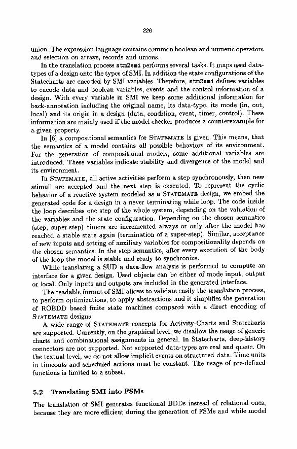
staidom (Generate an optimized domain for ROBDD generation) The size of the ROBDDs depends very heavily on the ordering of the ROBDD variables. Even though reordering techniques are used during the ROBDD generation, the initial ordering of the ROBDD variables is important. This tool tries to find a good variable ordering for the ROBDDs before any ROBDD is computed. It analyses the data flow within the SMI program and determines the dependencies between the SMI variables and thus between the ROBDD variables. Using special heuristics we developed, the tool produces an initial ordering that is taken by the compiler from SMI to FSM.
mput bits
tamagotchi 26 11 + smidet
+ smiopt 11 + smired 8 + smidom 8
state bits timelBDD nodes
75 0.67s 2677 75 0.58s 1801 60 0.35s 1741 60 0.32s 1735 60 0.29s 982
Table 1. Results of the optimizations
Table 1 shows the effect of using the above optimizers on the size of our sample application and the time to generate the FSMs 4. Each line adds one optimizer to the FSM generation and gives the corresponding results. We see that the number of ROBDD variables and the size of the model decreases dramatically using the optimizers. Other tested case studies gave similar results.
5.4 Retranslatlon of Error-Paths
The tools err2std and err2stm retranslate a produced error-path into a timing diagram or into a stimuli for the STATEMATE simulator. The STD shows the evaluation of the interesting variables over time, the simulator shows the dynamic behavior of the system until the faulty state is reached. Up to now, only error- paths produced by the the SIEMENS model checker can be retranslated.
6 E x p e r i m e n t a l R e s u l t s
In this section we present some results we got applying our tools on some STATEMATE designs. We concentrate on the generation of the FSMs and on
4 All results in this paper have been computed on an Ultra Spare 1 with 143 MHz
229
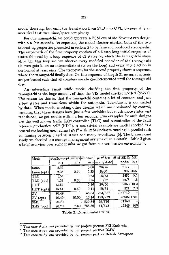
model checking, but omit the translation from STD into CTL, because it is an uncritical task wrt. t ime/space complexity.
For our tamagotchi, we could generate a FSM out of the STATEMATE design within a few seconds. As expected, the model checker checked both of the two interesting properties presented in section 2 to be false and produced error-paths. The error-path of the first property consists of a 6 step long initial sequence of states followed by a loop sequence of 52 states on which the tamagotchi stays alive. On this loop we can observe every modeled behavior of the tamagotchi (it even gets ill on an intermediate state on the loop) and every input action is performed at least once. The error-path for the second property shows a sequence where the tamagotchi finally dies. On this sequence of length 21 no input actions are performed such that all counters are always decremented until the tamagotchi
dies. An interesting result while model checking the first property of the
tamagotchi is the huge amount of time the VIS model checker needed (8627s). The reason for this is, that the tamagotchi contains a lot of counters and just a few states and transitions within the automata. Therefore it is dominated by data. When model checking other designs which are dominated by control, meaning that these designs have just a few variables but much more states and transitions, we got results within a few seconds. Two examples for such designs are the well known traffic light controller (TLC) and a controller of the fault tolerant production cell 5 (HDT). A non-trivial example we model checked is a central car locking mechanism (ZV) 6 with 12 Statecharts running in parallel each containing between 3 and 20 states and many transitions [5]. The biggest case study we checked is a storage management systems of an aircraft 7. Table 2 gives a brief overview over some results we got from our verification environment.
Model stm2smiloptimizers[smi2fsm [ # of bits in s I in s[ in s[input/state
0.66 0.35 0.23 0.15 O.26 0.11
45.64 13.14
829.84 786.39
26/75 s/6o 18/33 11/27 26/50 10/32
223/327 1147710 123/279 28602 99/720 21358 44/643 15249
# of BDD MC nodes in s
2177 - 982 8627
2485 5.i 1278 1.8 2363 10.2 521 2.3
1785
966
tama 2.35 tama (opt) 2.35 0.70 TLC 1.51 TLC (opt) 1.51 0.60 HDT 15.51 HDT (opt) 15.51 0.60 ZV 10.49 ZV (opt) 10.49 10.00 SMS 20.79 SMS (opt) 20.79 7.60,
Table 2. Experimental results
5 This case study was provided by our project partner FZI Karlsruhe 6 This case study was provided by our project partner BMW 7 This case study was provided by our project partner British Aerospace

230
The table shows times for the generation and the resulting sizes for five different case studies. Also, the times for model checking of some special verified properties are listed. For every study, the FSM has been computed with and without applying the set of optimizers. We see that the generation of the FSMs could be performed for all studies, but the sizes of the resulting FSMs differ very much depending on the optimizations. While model checking is possible on all optimized FSMs, model checking cannot be performed on the unoptimized FSMs in three cases. The times to generate and optimize SMI are almost linear in the size of STATEMATE design and thus not critical. The critical times result from the translation from SMI into FSMs and especially from the model checking itself. We can observe that the times spent for optimizations are covered by the improved times for model checking, e.g. 0.6s for HDT optimizations leads to 7.9s speedup in model checking. In addition, the table shows, that the time for verifying the tamagotchi is much greater than the times to verify the other studies, although it is a small design.
7 C o n c l u s i o n s a n d F u t u r e W o r k
In this paper a powerful environment for the verification of STATEMATE designs against symbolic timing diagram specifications has been presented and its usability on a sample application was demonstrated. Also some results on two industrial sized designs were given. Within our environment, almost all features of STATEMATE are supported and we are still working on expanding this set. Even though a set of optimizations can be performed during the verification task, we know that there is still a lot of space for further improvements. We expect to be able to verify much bigger designs in the near future. Even though the STATEMATE concepts of timeouts and scheduled actions are already supported, we still use timing diagrams without time annotations and therefore a normal CTL model checker. We are working on a time annotated extension of timing diagrams [8] in order to perform real-time model checking. Another direction for extending our work is abstraction.
Acknowledgmen t . We thank our project partners AHL, i-Logix and SIEMENS for providing the tools and for discussions. Furthermore we thank our project partners BMW, British Aerospace and FZI for the case studies. Special thanks to Hans Jiirgen Holberg for heavy testing of our toolset and to Werner Damm for constructive critics on this paper. Last but not least we thank the members of our group for helpful discussions and tools.
References 1. S.B. Akers: Binary decision diagrams. In: Transactions on Computers, No. 6 in
Vol. C-27, IEEE (1978) 509-516 2. K. S. Brace, Richard L. Rudell and Randal E. Bryant: Efficient implementation of
a BDD package. In: Proceedings 27th Design Automation Conference, Orlando, Florida, ACM/IEEE (1990) 40-45
231
3. J.R. Burch, E.M. Clarke, K.L. McMillan and D.L. Dill: Sequential circuit verification using symbolic model checking. In: Design Automation Conference ACM/IEEE (1990)
4. J.R. Burch, E.M. Clarke, K.L. McMillan, D.L. Dill and Jim Hwang: Symbolic model checking: 1020 states and beyond. In: Proceedings of the Fifth Annual IEEE Symposium on Logic in Computer science (1990)
5. W. Damm, U. Brockmeyer, H.J. Holberg, G. Wittich and M. Eckrich: Einsatz formaler Methoden zur ErhShung der Sicherheit eingebetteter Systeme im KFZ. VDI/VW Gemeinschaftstagung (1997)
6. W. Damm, H. Hungar, B. Josko and A. Pnueli: A Compositional Real-Time Semantics of STATEMATE Designs. In: Proceedings of COMPOS 97, edt. H. Langmaack and W.P. de Roever, Springer Verlag, to appear 1998
7. W. Damm, B. Josko, R. SchlSr: Specification and verification of VHDL-based system-level hardware designs. In: E. BSrger, editor, Specification and Validation Methods. Oxford University Press, (1995) 331-410
8. K. Feyerabend and B. Josko: A Visual Formalism for Real Time Requirement Specifications, Transformation-Based Reactive Systems Development. In: Proceedings of 4th International AMAST Workshop on Real-Time Systems and Concurrent and Distributed Software, ARTS'97, edt. M. Bertran and T. Rus. Lecture Notes in Computer Science Vol. 1231. Springer Verlag (1997) 156-168
9. T. Filkorn, SIEMENS AG: Applications of Formal Verification in Industrial Automation and Telecommunication. In: Proceedings of Workshop on Formal Design of Safety Critical Embedded Systems, (1997)
10. D. Harel: Statecharts: A Visual Formalism for Complex Systems. In: Science of Computer Programming 8, (1987)
11. D. Harel, H. Lachover, A. Naamad, A. Pnueli, M. Politi, R. Sherman, A. Shtull- Trauring and M. Trakhtenbrot: STATEMATE: A working environment for the development of complex reactive systems. In: IEEE Transactions on Software Engineering, (1990) 403-414
12. D. Harel and A. Naamad: The STATEMATE Semantics of Statecharts. In: ACM transactions on software engineering and methodology, Vol 5 No 4 (1996)
13. D. Hazel, A. Pnueli, J.P. Schmidt and R.Sherman: On the Formal Semantics of StateCharts. In: Proceedings of First IEEE, Symposium on Logic in Computer Science, (1987)
14. D. Harel and M. Politi: Modeling Reactive Systems with Statecharts: The STATEMATE Approach. i-LOGIX INC., Three Riverside Drive, Andover, MA 01810, Part No, D-1100-43 (1996)
15. E. Mikk, Y. Lakhnech, C. Petersolm and M. Siegel: On Formal Semantics of Statecharts as Supported by STATEMATE. In: Proceedings of BCS-FACS Northern Formal Methods Workshop, (1997)
16. S. Owre, N. Shankar and J.M. Rushby: A Tutorial on Specification and Verification Using PVS. In: Computer Science Laboratory, SRI Int., (1993)
17. R. SchlSr: Symbolic Timing Diagrams: A visual formalism for specification and verification of system-level hardware designs. In: Dissertation (to appear), Universit/it Oldenburg, (1998)
18. R. SchlSr and W. Damm: Specification and Verification of System-Level Hardware Designs using Timing Diagrams. In: EDAC-EUROASIC, (1993)
19. VIS: A system for Verification and Synthesis. The VIS Group. In Proceedings of the 8th International Conference on Computer Aided Verification, Springer Lecture Notes in Computer Science, Vol. 1102, Edited by R. Alur and T. Hen~inger, New Brunswick, NJ (1996) 428-432
![Modellbasiertes Testen vs. Testgetriebene Modellierung bTabX]V RP] QT caTS bA aWAe bWT BCTaT]RT AU QcVa Qcb ] ... • Integration$mit$ Testwerkzeugen. ... Rational$Statemate/ Rhapsody](https://img.dokumen.tips/doc/110x75/5b2a8fe47f8b9a6b3c8b552d/modellbasiertes-testen-vs-testgetriebene-modellierung-btabxv-rp-qt-cats-ba-awae.jpg)