Embed Size (px)
Citation preview

AD-A264 371
-W A, 'ID-CP-522
A&GARD4 ADVISORY GROUP FOR AEROSPACE RESEARCH & DEVELOPMENT
7 RUE ANCELLE 92200 NEUILLY SUR SEINE FRANCE
DTICE LECTE
AGARD CONFERENCE PROCEEDINGS 522 MdAY 1 41993fl
TacSats for Surveillance, CVerification and C31(Les Satellites Tactiques (TacSats)pour la Surveillance, la Wrification et la C31)
Papers presented at the Avionics Panel Symposium heldin Brussels, Belgium from 19th-22nd October 1992.
7:3!E- A
_ - NORTH ATLANTIC TREATY ORGANIZATION
Published February 1993
Distribution and Availability on Back Cover

AGARD-CP-522
ADVISORY GROUP FOR AEROSPACE RESEARCH & DEVELOPMENT
7 RUE ANCELLE 92200 NEUILLY SUR SEINE FRANCE
ii7;(' TAjS
AGARD CONFERENCE PROCEEDINGS 522d
TacSats for Surveillance,
'- - / --
Verification and C31 Ud•,,,7,
(Les Satellites Tactiques (TacSats) A-WfciD,)Ity Codespour la Surveillance, ]a Wrification et la C31) D ,1 djor
Papers presented at the Avionics Panel Symposium heldin Brussels, Belzium from l9th-22nd October 1992.
_ North Atlantic Treaty OrganizationOrganisation du Trait6 de I Atlantique Nord
I.

The Mission of AGARD
According to its Charter. the mission of AGARD is to bring together the leading personalities of the NATO nations in the field,of science and technology relating to aerospace for the following purposes:
- Recommending effective ways for the member nations to use their research and development capabilities for thecommon benefit of the NATO community:
- Providing scientific and technical advice and assistance to the Military Committee in the field of aerospace research anddevelopment (sith particular regard to its military application):
- Continuously stimulating advances in the aerospace sciences relevant to strengthening the common defence posture:
- Improving the co-operation among member nations in aerospace research and dce elopment:
-Exchange oi scici:.:ic and technical information:
- Providing assistance to men,;er nations for the purpose of increasing their scientitic and technical potential:
- Rendering scientific and technical assistance, as requested. to other NATO bodies and to member nations in connectionwith research and development problems in the aerospace field.
*The highest authority within AGARD is the National Delegates Board consisting of officially appointed senior representativesfrom each member nation. The mission of AGARD is earned out through the Panels which are composed of experts appointedby the National Delegates. the Consultant and Exchange Programme and the Aerospace Applications Studies Programme. Theresults of AGARD work are reported to the member nations and the NATO Authorities through the AGARD series ofpublications of which this is one.
Participation in AGARD a.tivities is by invitation only and is normally limited to citizens of the NATO nations.
The content of this publication has been reproduceddirectly from material supplied by AGARD or the authors.
Published February 1993
Copyright C AGARD 1993All Rights Reserved
ISBN 92-835-0700-2
Printed by Specialised Printing Services Limited40 Chigwell Lane, Loughton, Essex IG1O 3TZ

Theme
The recent Desert Storm operations underscored the essential need for space systems to fight and win a theatre war. Anemerging concept for space systems currently receiving widespread attention for the 90s is characterized by the term -TacSats"(also called Cheap Sats, Light Sats, Small Sats etc.). These satellite systems are characterized by relatively low costs andlightweight satellites with performance capabilities focused at meeting theatre command requirements. This is in contrast withcomplex. heavy satellites focused on meeting national requirements. The TacSats concept may be particularly appropriate forthe ct'rrent environment of declining defence budgets and conventional force reductions. These systems offer capabilities whichcan be purchased incrementally in contrast to traditional space systems which require future expenditue. Ithey can be launchedby smaller, less expensive launch vehicles, perhaps controlled by the local theatre commander.
TacSats may offer a flexible economical solution for NATO's surveillance, communications, and command and control needs inthe 90s. In an environment of reduced forces, it becomes more important to know precisely where potential enemy forces arelocated, what is their strength, where they are going, etc. This is vital in order to operate effectively with smaller forces. Spacesystems offer an effective and perhaps the only maeans of performing these functions. Affordable TacSats developed for NATOmay offer a way to counter a changing threat in an environment of reduced budgets and force structures.
The Symposium addressed the following topics:
TacSats Svstems- NATO architecture and system engineering- Payload concepts and designs- Spacecraft bus concept and designs- Launch vehicles for the SATS- Mission control and user equipm..nt
Space System Technologies of the Future- EHFR SHE UHF antennas, receivers- Optics and electro optics components- IR detectors. focal planes, coolers- Materials and structures- Communication and telemetry- Data processing, on-board processing- Power systems. solar cells, batteries- Built-in test and non destructive testing- Propulsion technologies.
iii

The~me
Les operations ricentes ((Tempite du De6sertz. ont souligne le besoin vital de se doter de systemes spattaux susccpubles de meneret de gagner una guerre de th~tre. Un nouveau concept de syste'mes spariaux pour les annees 1990, qui suscite beaucoupd'interit a l'eure actuefle, est caract~ris6 par Re terrne oTacSats* (appele aussi CheapSats. LightSats. Sm"ai~as etc.). Cessyst~mes sont caracterisds par des coilts relativement modiques et des satellites legers avec des performances etudices pourr~pondre aux besomns du conunandement du th~tre, par opposition aux satellites lourds et complexes desrines ýt satisfaire auxbesoins nationaux.
Le concept iTacSatso parait particuli~rement adapte au contexte actuel de compression des budgets de defense nationale et dereduction des forces armides. Les capacit,&s offertes par ces syst~mes peuvent &tre acquises de faqon progressive. contrairementaux syst~mes spatiaux classiques, qui sont toujours accompagmis de cotits additionneis. En outre, ils peuvent etre mis sur orbitepar des vehicules de lancement plus petits et moins co~teux. commandes eventuellement par le commandant du thckire local.
Les TacSats semblent offrir une solution 6conomique et souple au probleme des besoins de I'OTAIN en matenel de surveillance.de tdl~commut-dcations et de cominandement et contr6le pour les ann~es 90. Dans une situation de forces red uites. ii importe desavoir oii les forces ennemies potentielles pourraient ýtre situees. quel est leur nombre. quelle est leur route etc. (Cs informationssont indispensables ý tout d~ploiement efficace d'un nombre r~duit de troupes. Les systemnes spatiaux offrent peut-ecre lki 'eulepossibilit6 d'ex~cuter ces fonctions d'une maniere efficace. Dans cc cas. des TacSats ddveloppes pour l'OTAN. ai un pnixabordable. permettraienr de contrer une menace q'ui ývolue, dans un monde Cu les budgets CI ICS Structures des forces sont endiminution.
Le symposium a traite des sujets suivants:
Systemes <(TacSats)>-Architecture et ingeni~rie des systcmes OTAN-Concepts et etudes de ]a charge utile
Concepts et 6tudes des bus pour v~hicules spatiaux-Lanceurs SATS
Technologies de demain pour systemes spatiaux- Antenxses et recepteurs EHF. SI-F et UHF- Composants optiques et electro-optiques- D~tectcurs IR, plans focaux, refroidisseurs- Structures et mat~riaux- Telcommunications et teleme'tric- Traitement des donnees et ordinateurs embarques- R~seaux d'alimentation. cellules solares. batteries- Disposififs de test integres et essais non destruciffs.
iv

Avionics Panel
Chairman: Eng. Jose M.G.B. Mascarenhas Deputy Chairman: Colonel Francis CorbisterC-924 Cored 21 Log Wingc, o Cinciberlant Hq Quartier Roi Albert ler2780 Oeiras Rue de la Fusee, 70Portugal B- 1130 Bruxelles
Belgium
TECHNICAL PROGRAMME COM MITTEE
Chairman: D)r Hugo RuggeVice President
I ab Operations Development (GrpThe Aerospace CorporationPO. Box 92957Los Angeles. CA 9)01009-29i57United States
Programme Committee Members
Dr John Butterworth 1)r WoIfg-ang KeydelManager. Military Satellite Communications DirectorC.R.C., 3701 Carlinig Asenuc DLRStation H. Ottawa, Ontario. K2H 8S2 Institut fur HochfrequenztechnikCanada D-80311 Wessling Oberptaffcnhoten
GermanyDr Ing. Luigi CrovellaAentalia Dr Ron W MacPhersonGruppo Sistemi e Teleguidati Directorate of Scientific Policy10072 Caselle (Torino) National Defence HeadquartersItaly Constitution Buidine, 7th Floor
305 Rideau StreetMr CD. Hall Ottawa. Ontano K 1 A OKK2Marconi Space Systems Ltd CanadaAnchorage Road
PortsmouthHants P03 5PUUnited Kingdom
PANEL EXECUTIVE
LTC R. Cariglia, IAF
Mail from Europe: Mail from US and Canada:AGARD-OTAN AGA RD-NATOAttn: AVP Executive Attn: AVP Executive7, rue Ancelle Unit 2155192200 Neuilly-sur-Seine APO AE (19777France 93-10603
Tel: 33(1)47 38 57 68Telex: 610176 (France)
Telefax: 33 (1) 47 38 57 99
93 5 04 9

Contents
Page
Theme iii
Thime iv
Avionics Panel and Technical Programme Committee v
Reference
Technical Evaluation Report Tby C.E. Heimach
SESSION I - TACSAT CONCEPT AND NEED
Military Requirements for a Tactical Space System Itby R.M. Broussard, R.H.Tate III and DA.Tyson
The Italian Approach to Tactical Use (f Space 2°by F. Borrini
Tactical Satellites 3by F.H. Newman
Evolution or Revolution - The Catch 22 of TacSats? 4by C.J. Elliott
SESSION I1 - TACSATS - ASPECTS
Paper 5 cancelled
TacSat Ground Control and Data Collection 6by C.G. Cochrane
Paper 7 cancelled
TacSat-Spacecraft Bus Concept and Design: Application of a Multimission Bus for 8TacSat in LEO (English and French)
by G. Richard
A Model to Comparatively Assess Alternative Satellite Communications Systems Options 9*
by J.E. Brown
SESSION III - TACSAT APPLICATIONS - SYSTEMS
Systeme de Navigation par Satellites a Couverture Europeenne 10par H. Baranger, J. Bouchard et T. Michal
Tactical Satellites for Air Command and Control I Iby M. Crochet. J. Cymbalista and L. Levtxue
Concept of Small Surveillance Satellites in the Context of an Overall Space System 12*by U.M. Erich, W.A. Kriegl and K.-L. Bitzer
Concepts of Sensors and Data Transmission for Small Tactical 13*Surveillance and Verification Satellites
by K.-L. Bitzer, H.Otl, K.H.Zeller and S. Craubner
t Not available at time of printing.Printed in Classified publication CP522 (Supplement).
vi

Reference
SESSION IV - PANEL DISCUSSION
SESSION V - COMMUNICATIONS CONCEPTS
Considerations for NATO Satellite Communications in the Post-2000 Era 14by A. Nejat Ince
Paper 15 cancelled
Advanced Technologies for Lightweight EHF Tactical Communications Satellites 16by D.R. McElroy. D.P. Kolba. W.L. Greenberg and M.D. Semprucci
Synchronization Techniques for Medium Data Rate EHF MILSATCOM Systems 17by G. Boudreau and M. Schefter
Terrain and Coverage Prediction Analyses for Non-Geostationary 18Orbit EHF Satellite Communications
by MT. Ahmed
SESSION VI - LAUNCH SYSTEMS
Launch Vehicles for Lightweight TacSat Deployment 19bv C.L.Whitehair and M.G. Wolfe
Spacecraft and Launch Systems for TacSat Applications 20by C. Shade. G.D. Rye and R.H. Meurer
Optimisation de Lancements Multiples 21par L. Zaoui et B. Christophe
SESSION VII - SPACECRAFT BUS
QuickStar - System Design, Capabilities and Tactical Applications 22of a Small, Smart Space System
by T.P. Garrison and N.T. Anderson
Attitude- and Orbit Control Subsystem Concepts for TacSats 23by H. Bittner. E.Bruderle. M.Surauer and M.Schwende
Electric Propulsion for Lightsats: A Review of Applications and Advantages 24by G. Perrotta and G. Cirri and G. Matticari
SESSION VIII - ADVANCED TECHNOLOGY
An Overview of DARPA's Advanced Space Technology Program 25by E. Nicastri and J. Dodd
SESSION IX - RADAR CONCEPTS
SAR Sensors on TacSats: A Feasiblity Assessment 26by G. Perrotta
A TacSat SAR Concept 27by C.D.Hall. CJ. Baker. G.E. Keyte and L.M. Murphy
Low Cost TacSat for NATO Surveillance 28by C.S. Hoff
vii

Reference
Microwave Applications of Small Satellites in Low Earth 0. ý:t 29*1y N. Lannelongue. E. Lansard and M. Collomby
SESSION X - ELECTRO-OPTICS CONCEPTS
Optical Reconnaissance Tactical Satellite 30"by J. Cymbalista. G.Cerruti-Maori and C.Carton
Cost Effective TacSats for Military Support 31by M.T. Brodsky. M.D. Benz and J.T. Neer
TacSats for Regional Surveillance 32*by M.C. Chapman
TacSat Meteorological Payloads 33by D. Hickman
SESSION XI - PANEL DISCUSSION D
"Printed in Cla•sified publication CP522 (Supplement).
Vii

i*1
TECHNICAL EVALUATION REPORT
Charles E. HeimachConsultant
30543 Rue de la PierreRancho Palos Verdes, California, USA 90274
SUMMARY Weather - good information, but the data
The symposium was highly successful in that it disseminanon was poor.
brought together a broad spectrum of the NATO space Navigation - great, but not enough receivers.technical community with quality papers on themissions, applications, and technical aspects of Imagery - a controversial subject. While there wasTACSATs. The main topics centered on surveillance not enough surveillance, it was actually viewed asand communication systems, and the issue of n enough seiaue , it wsculewsdetermining requirements. At the completion of the a failure because of dissemination problems.symposium, it was clear that state-of-the-art totalsympostems coud b s bult that wouldabe- responsv totae As a result, the overall space rating can be viewed assystems could be built that would he responsive to the flostheater commander at a reasonable cost. While thelevel of technical detail varied; that is, more emphasis Capability - greaton the satellite options than the ground systems, there Payload tasking - moderatewas sufficient detail to make the case for the validity of Dissemination - terriblethe TACSAT concept as discussed in the symposiumtheme. He went on to emphasize that the reason for this "card"
The output from this symposium will be the central rating goes back to what the warfighter wants. Fie
point of departure for the Working Group 16 efforts on wants: continuous availability, flexibilityTACSATs for NATO. In this regard, the symposium availability to the end use.. Put another way, from awas an outstanding success. combat perspective the warfighter will ask:
- Can I get what I want when I want it?TECHNICAL CONTENT - Can I distribute it to my forces?
The symposium was opened with an address by Robert In closing, Gen. Dickman challenged the symposiumDickman, Brigadier General, USAF, who is the Deputy to focus on the deficiencies.Chief of Staff for Plans at Air Force Space Commandin Colorado Springs, Colorado, USA. His perspective I. Improve distributionwas from the warfighter's point-of-view within whichhe challenged the audience of mostly scientists and 2. Improve data streams.engineers to focus on the needs of the user;emphasizing, that if TACSATs are to be a part of space 3. Develop new space systems: but, avoidin the future, they must be measured in terms of If, ir uniqueness, concentrate on intcroperability, andunique contributions to mission success. ensure that we can exercise as we fight.
To make his point, Gen. Dickman expressed the belief The challenge for TACSAT will be:that space will be a dominate factor in any futureconflict; and, as a resc:ht, will have to improve, not What are the needs?decrease, in the future. He emphasized that while this What are the options?belief is widely accepted, in an age of decreasing What is possible now?resources, requirements and affordability must come What are the "measures of effectiveness?"together. Therefore, the developer must seek out theview of the warfighter in an effort to identify critical Session I - TACSAT Concept and Needspace deficiencies. In this regard, the developer will bedealing with a customer who is smarter, who will The intent here, was to "set the stage" - WHAT AREdemand more from space, and who will insist that the WE TALKING ABOUT?.space capabilities be there during hostilities.
In this session, as with almost the entire symposium,To emphasize these points, Gen. Dickman gave a space two mission areas received the most attentioi -"report card" on Desert Storm. surveillance (imagery) and communications. Of those
two mission areas, surveillance took the "lion s share"Communication - never enough, not mobile of the group's attention, with most of the discussionsenough, and the terminals were inadequate, centered on resolution.

From the four papers. there were several areas of bus, and a model for assessing various COMSATconsensis, two areas of divergent opinions, and one options,outstanding issue.
While not giving specific answers to TACSATConsensus command and control, the session stressed the
importance of this area and ho v such answers might beTotal system designs must provide for flexibility, addressed in future analyses. In the "bus" area, theresponsiveness, on-demand support. and high point was made that such bus's have been flown in arevisit times, R&D mode and that reasonable bus's could be provided
for TACSAT low earth orbit missions.That TACSATs can be used in tandem with coresystems by: raising mission area responsiveness. Session III - 'rACSAT Applications -
selecting orbits to match the threat, concentrating Systemson a specific geographic area. and filliig in for afailed primary system. A wide variety of mission areas was discussed;
however, the greatest emphasis was in navigation,They must generate a field useablc product communications and surveillance. In general, the(surveillance orientation), technical emphasis was on techniques for moderate
capable systems with upper limits on spacecraft weight
Any new design must be compatible with current and reduced complexity. Of particular note, was theterminals and allow for realistic training. overwhelming attention to limiting the warfighter
,support to specific geographic areas rather than globalAffordability must be paramount through or continental support. These views can be seen in thecommonality, a common bus approach. using following distillation of the output from four papersitems off-the-shelf. and controlling requirements. presented in this session.
While it was generally agreed that TACSATs fall Navigationin tne wcight regime' of 300-7(AX) kg, the validityof continued use of this definition b,-came an area A concept was discussed that used four to nine satellitesof divergent opinion, at geostationary orbit versus the medium earth orbit of
GPM In keeping with system simplicity. lawer costDivergent Opinions (through lighter weight), and limited geographic
coverage, the concept had the following features:Within this session, and as the symposium progressed.there was continued discussion concerning two Equivalent GP- capabilityopinions. While there was no consensus on theseopinions, it was agreed that Working Group 16 must Ground based atomic clock for lighter weightlook at them further. They are: and simpler spacecraft
I. Large systems can be considered as TACSATs Coverage limited to Europe, the Nlid-cast, adif data dissemination and payload tasking can Africabe more responsive to the warfighter.
Three satellites launched simultaneously on2. TACSATs do not necessarily have to be Ariane.
launch-on-demand systems: they can also bestored on orbit in a dormant state ready for Communicationsrapid activation and repositioning.
The discussion here centered mostly on comsatIssue applications as they relate to Air Command & Control.
Of particular note was the point that TACSATs areThere was one issue - how do we come to grips with a needed in all areas and that their configuratiors shouldformal statement of the need. Imbedded in this issue is include:whether a statement of need is necessary for TACSATor if TACSAT is a technical option whose "time has Bi-directionalcome" and it is now ready for consideration in relation Broadcastingto a broader sphere of needs. Ground to ground
Ground to airSession II - TACSATs - Aspects
However, communication type TACSATs were seen asThis session covered a broad range of TACSAT a primary means for alleviating the problem of Airconcerns ranging over the areas of data collection, Tasking Order dissemination.system control functions, viability of a multimission

While the discussions in this area presented new Session IV - Panel Discussionthinking in how COMSATs could contribute to the aircampaign and, to some degree, ballistic missile defense; The objective of this session was to engage themore analysis is needed to determine the value of audience in addressing any issues and concerns that mayTACSATs as a specific class of satellite. This is have come up in the prior sessions. Four major issuesconsistent with the issue raised in Session I concerning were discussed, although no resolutions were agmcdthe use of large satellites as TACSATs. upon. The issues were:
Surveillance - How are requirements to be established?
This area received the most attention in this session, - Should TACSAT be strictly theater orientd?appearing in three out of the four papers.
- Will TACSAT be complimentry to the majorAs with communications, surveillance satellites were space systems?presented as key elements in developing the AirTasking Order and in supporting ballistic missile - What launch strategy is appropriate?defense. The function of surveillance satellites wasconsidered prime in detecting airbase activation, Wid These issues will oe a prime concern of Workingdetection, launcher detection, detection of missile Group 16.launch preparation, -'nd missile launch detection.Hov ever, specific requirements that allow for the use of The value of this session was not in the discussions,TACSAT class satellites have yet to be defined, but in the bringing forth of these four key issues.
Some time was spent on the potential roles TACSATs Session V - Communications Conceptsmight play from a systems point-of-view. It wasemphasized that surveillance TACSATs could: In this session the emphasis was on technology and
how it might lead to TACSAT type communicationReduce system complexity satellites. The main emphasis was on EHF; although
there was some discussion of SHF.Enhance observation capabilities (more fromquantity than quality) The flow of the session was part.cularly well done with
Dr. Ince leading off with a discussion of WorkingAchieve high revisit of specified sites Group 13's efforts on NATO Satellite
Communications, which was started in 1986. In theProvide a quick concentration of resources. discussion, he reminded the audience that our past
emphasis was oriented to the strategic mission whereHere again are the points that TACSATs play best in the systems had to be highly survivable, easureactivities that are geographically localized and that continuity of service, provide ECCM, and provide lowrequire quick reaction to a situation, capacity communication for emergencies.
At this point, came the first discussions of the But times have changed. Dr. Ince emphasized thattechnical and operational viability of certain levels of satellites should be smaller and cheaper, with launchresolution, orbital altitudes, spacecraft weight, and flexibility by employing systems such as clusteredsurveillance techniques. satellites. He also emphasized some movement from
SHF to EHF. Most importantly, Dr. Ince provided aResolutions seemed to fall in the 3-5 meter listing of NATO actionsregions, with some excursions to 1.4 meters.
- Define NATr and National requirementsThe orbital altitudes ranged from 280 km to600 km. - Develop and agree on an architecture
The spacecraft weights were in the 600 to 750 - Define the technologieskg range.
- Encourage companies to join togei'- -
Surveillance techniques included electro-opticaland synthetic aperture radar (SAR). The remaining papers discussed the technologies that
will make smaller EHF satellites possible and some ofAt issue in this area was the acceptable resolution. As the problems that might be expected at thesealways, the user asks for the best; however, it was frequencies. In general, the emphasis was to providegenerally agreed that best in surveillance means large, technologies that would allow more users to takeexpensive, and limited in quantity. This item remained advantage of the AJ characteristics of EHF whileas a contentious issue throughout the symposium. operating at medium data rates rather than low data
rates. The technology emphasis was on variable (1) Max 500 kg LEObeamwidth antennae, frequency synthesizers, and (2) Max 1500 kg LEOprocessors. In the case of the antenna technology, the Max 500 kg GTOobjectives were for easier operation in elliptical orbitsand for ease of switching geographic locations for Therefore, smaller TACSATs can have multiplesatellites in geostationary orbits. For frequency options where as the largc TACSATs (particularly tosynthesizers and for processors, the emphasis was on GEO and elliptical) must be stored on orbit or settle forsignificant weight and power reductions that would 20 to 60 days turn-around.allow for payloads in the 100 kg and 290 w regime'swith terminal capacities of 27 LDR channels at 45 It was generally agreed that it would be prohibiuvelykbits and 17 MDR channels at 3 mbits. expensive to convert MLV-3, Delta II, Atlas 11. and
Ariane to turn-around times that are commensurate withOther discussions included MDR EHF synchronization Pegasus and Taurus. On the other hand, the MLV-3,techniques for minimizing acquisition times and an Delta 11, Atlas I1, and Anane will be cost compeutiveexamination of interference from mountains and for store-on-orbit because of their ability to launchfoliage, more than one TACSAT; the issue being, will the
military situation at a given instant allow for such anEssentially, this session verified that the technology is approach? Working Group 16 will have to address thisavailable for TACSAT type communication satellites, issue.particularly at EHF. The question remained concerningthe adequacy of such systems for military needs. Session Vll - Spacecraft BusCertainly, the capacity of such systems can now bedefined with great confidence and no doubt the same can The question of building a common bus with thebe said for cost. The question is, is the terminal appropriate attitude control was addressed in thiscapacity described above cost effective under a range of session. In general, the papers confirmed that low costscenarios? common spacecraft buses can be built, although it w-as
also recognized that some penalties would be realzexlSession Vi- Launch Systems from over optimized or sub optimized subsystems.
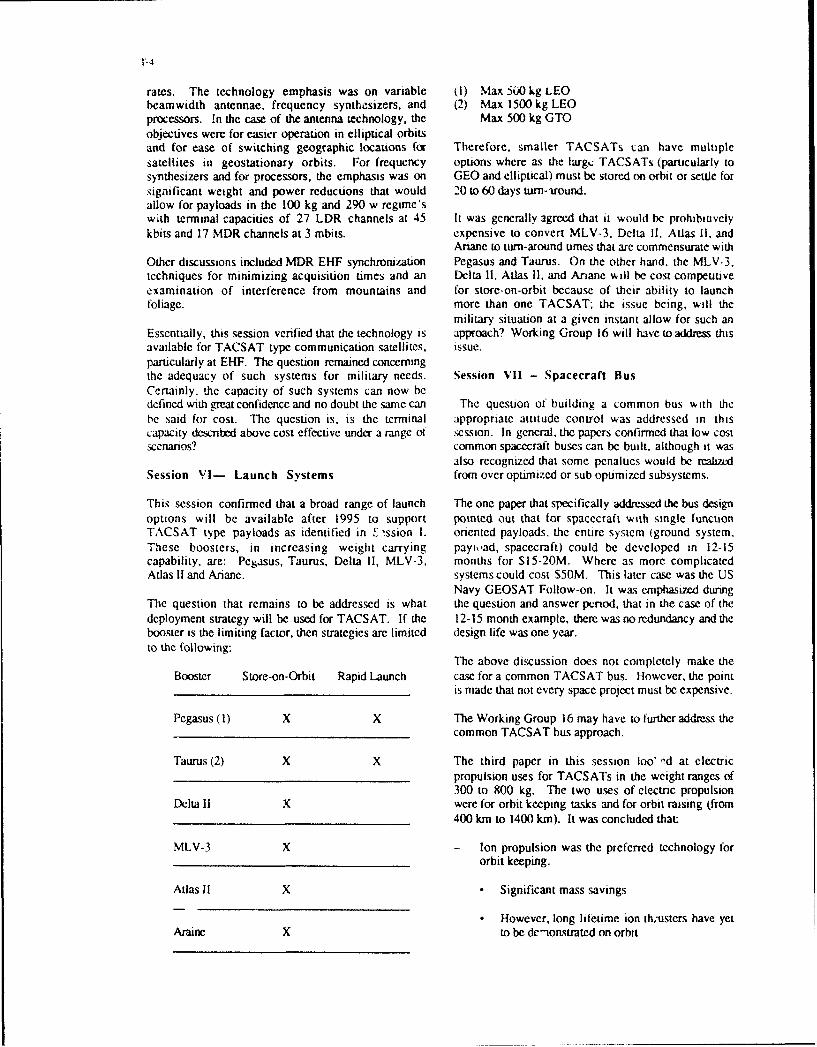
This session confirmed that a broad range of launch The one paper that specifically addressed the bus designoptions will be available after 1995 to support pointed out that for spacecraft with single functionTACSAT type payloads as identified in ' ýssion 1. oriented payloads, the entire system (ground system.These boosters, in increasing weight carrying payviad, spacecraft) could be developed in 12-15capability, are: Pegasus, Taurus, Delta 11, MLV-3, months for S15-20M. Where as more complicatedAtlas 1I and Ariane. systems could cost S50M. This later case was the US
Navy GEOSAT Follow-on. It was emphasized duringThe question that remains to be addressed is what the question and answer penod, that in the case of thedeployment strategy will be used for TACSAT. If the 12-15 month example, there was no redundancy and thebooster is the limiting factor, then strategies are limited design life was one year.to the following:
The above discussion does not completely make theBooster Store-on-Orbit Rapid Launch case for a common TACSAT bus. However, the point
is made that not every space project must be expensive.
Pegasus (1) X X The Working Group 16 may have to further address thecommon TACSAT bus approach.
Taurus (2) X X The third paper in this session loo' !d at electricpropulsion uses for TACSATs in the weight ranges of300 to 800 kg. The two uses of electric propulsion
Delta 11 X were for orbit keeping tasks and for orbit raising (from400 km to 1400 km). It was concluded that:
MLV-3 X - Ion propulsion was the preferred technology fororbit keeping.
Atlas II X . Significant mass savings
. However, long lifetime ion th.-usters have yetAraine X to be dc"ionstrated on orbit

T-5
- Low power arcjets are the best candidates for orbit of the region of concern (2000 x 2000 kin), which intransfer and raising. turn reduced the duty cycle (5-30%) which reduced the
weight and, to some extent, reduced the size of the
In general, more work is needed for electric propulsion; antenna. Other spacecraft parameters fell into thehowever, it should be supported and examined for following areas:introduction into any TACSAT program.
X-bend or C-bandSession VIII - Advanced Technology 300 to 500 km altitude
200 to 400 mbit data rateThis session was divided into two discussions - the 6 to 8 satellite constellationDARPA (USA) space technology efforts and CAMEO. Phased array antenna
4 x 2 meter antennaThe DARPA technology discussion told of significant 2-5 meter resolutionstrides being made to reduce the cost of doing Jusiness 30 images per passin space. It is more appropriate for the reader toexamine the paper than to present a detailed summary There was a unanimous call for a demonstration flight.here. However, a brief summary is appropriate. The overall feeling was that a SAR spacecraft, built toThis program includes: the above specifications, is state-of-the-art.
- Pegasus Additional papers were presented that discussed- Taurus lightweight, store and forward microwave applications,- DARPASAT a maritime application of a SLAR and an altimeter to- Optical technology for light weight systems determine wave heights.- Submarine laser communications technology- EHF technology Session X - Electro-Optic Concepts- Satellite subsystems- Common buses This discussion followed the pattern seen in the SAR
session. In general it was believed that state-of-the-artAn example of the progress being made can be seen in E-O TACSATs could be built according to thethe EHF technology work. This technology is on its following:way to lowering spacecraft weight and power by >50%. 1-SM resolutions
250-450 km altitudeThe overall program will use smaller satellites to 350 to 650 kg spacecraft weightquickly validate technologies so large satellites can be 200 to 300 mbs data rateprocured using more advanced technology.
Three additional points were made: (1) the groumdA description of CAMEO was presented. Its objectives station could be air transportable; (2) a convincingare: demonstration could be conducted for $50- 100M; and
(3) a $50M price per satellite is achievable.- Multi-spectral small satellite- DOD/civil environmental and weather As with the radar SAR, the group felt a demonstration
- Direct downlinking of data was absolutely necessary to get something into the- Use of a common bus hands of the user.
During the question and answer period, the status of Session XI - Panel DiscussionCAMEO was requested. The answer was that fundingwas deferred by Congress even though it had the full This session reviewed the outputs from each sessionsupport of DOD. followed by questions and answers with the audience.
The discussions centered on three themes - can weSession IX - Radar Concepts achieve the TACSAT objectives, how much resolution
can we expect from surveillance systems, and how doAs with the following session, this session addressed a we identify requirements.specific technique for battlefield surveillance - usingradar in the synthetic oper-ture mode. The papers were RECOMMENDATION:in-keeping with the general approach of TACSAT. thatof supporting theater operations. This point was From the content of the papers, it appears thatshown as pivotal in allowing a reasonable weight TACSAT type spacecraft for surveillance ardspacecraft so that it fit the smaller class satellite communications could be of great value to NATO.category. In general, the spacecraft weights fell in the While such systems will be more affordable than larger500 to 800 kg regimes. In the past, most radar more capable systems, they will not be procured by anyspacecraft weights were in the 5000 kg class; so why one member nation and therefore should be apprachedthe difference? Basically, the difference was in the size as a joint international effort.

T-6
These are thiee specific recommendations: (1) Thesepapers should be used as the foundation for theWorking Group 16 efforts. (2) The results of WorkingGroup 16 should then be briefed to the member nationsand NATO headare•rs. (3) A NATO tam should beestablished to develop technical and operationaloptions, with costs, to be reported out to NATO byearly 1994.
3-I
TACTICAL SATELLITESF.H. Newman
The Aerospace CorporationP.O. Box 92957
Los Angeles, CA 90009
ABSTRACT DISCUSSION
The concept of a Tactical Space System, "TACSAT" The purpose of this paper is to put into context theis a means to provide a rapid, on demand, role of the tactical satellite and present some sampleaugmentation of the backbone U.S. military space applications in order to provide an introduction tosystems. Such augmentation would be valuable to the more detailed design and operations papers totemporarily replace lost capability or in times of crisis, follow. The Tactical Space System, commonlyto accommodate surge demands. Because referred to as TACSAT, was envisioned asaugmentation needs are not always known a-priori, it providing a space capability directly under thewould be desirable to be able to rapidly constitute control of the military field commander. Whenthe appropriate payload-satellite bus combination to needed, the spacecraft can be quickly assembled toaccommodate the need for a specific space provide the required mission capability and quicklycapability. To do this, one can envision a standard launched or repositioned in orbit to provide thebus capable of accepting a variety of payloads, or required coverage. The system would bebetter yet, a single spacecraft designed to perform compatible with, and operate within the larger inseveral different missions. Both options are place space architecture, or as a stand aloneconsidered. A number of potential missions exist in capability. In either case, however, its operationthe areas of surveillance, navigation, environmental would be transparent to the user; that is, the usersensing and communications. Of these, two are would be able to use the same ground terminalspresented as strawman concepts; surveillance and already in use for interaction with the largercommunication. For surveillance, an electro-optical backbone satellite systems. The need for apayload is described that could be used for missile TACSAT can arise from several circumstances. Firstsurveillance, theater targeting or weather data using would be to augment the existing spacethe same optics, focal plane and processor. The infrastructure in order to accommodate changes insatellite orbit selected dictates which mission is requirements that could be caused by changes inperformed. For communication, both SHF and EHF the military alert posture, e.g., as we go from peacepayloads are defined to provide theater coverage to crisis to war. TACSAT could also be deployed iffor the tactical user. The advantages and penalties areas of military instability shift from onethat accrue to the use of a common bus are also geographical location to another. It may, in fact,explored. In addition, launch options are identified become necessary to cover several geographicaland a comparison made between "launch-on- locations simultaneously. During Desert Storm, fordemand" and "launch-on-schedule" strategies. example, space assets were repositioned to supportPotential timelines for rapid launch are shown based operations in the Persian Gulf. Had a crisis or conflicton parallel processing and checkout of spacecraft occurred in a different part of the world at that sameand launcher. This technique is compared with time, we would have been hard pressed to supportlaunching satellites on a routine basis and storing operations in both theaters. As I will show later inthem in orbit. Energy requirements for this paper, space launch systems are not veryrepositioning these stored satellites after they are responsive, nor are satellites stored in orbitactivated in time ca need are defined, generally designed to be maneuvered rapidly. If a
failure occurs in one of the backbone spacesystems, then TACSAT could be used to provide aninterim capability until that backbone constellationcan be restored. This situation occurred severaltimes in the U.S. military space program, particularly

3-2
when we have gone from one model satellite to a be possible to launch into the inclination of interestredesigned or upgraded one. If one looks at an and thereby obtain pertinent data on the first orbitalactual supply/demand curve it can be seen that for pass. Another means of obtaining responsivenessthe sake of economy, most space systems are requires the capability to reposition satellites alreadydesigned to provide a nominal capability. In general, in orbit. This is a particularly attractive option forthis capability is less than the peak demand satellites in the geostationary belt.requirements. Also, as mentioned earlier, thecapability may be reduced due to system failures. Of all the TACSAT characteristics, the one that isWhen a crisis occurs, the shortfall between demand absolutely essential is affordability. If a low unit costand supply could be quite significant, can be achieved the TACSAT concept can be an
attractive option especially in this era of limitedFor TACSAT to fill this gap, it must possess three defense spending. TACSATs can be incrementallymain characteristics; flexibility, responsiveness and acquired allowing the user to purchase the capabilityaffordability. The first criteria for TACSAT, flexibility needed at present and then add to that capability asmeans that it must be capable of supporting multiple the need arises.mission areas. These mission areas are generallydefined as surveillance, communications, navigation One method of achieving affordability is to maximizeand environmental monitoring. As I will discuss later design commonality across the spectrum ofin the paper, there are several ways to design a missions to be performed. In the ultimate, onesystem that is capable of performing more than one would desire to have a single satellite designof these missions. If we can achieve this flexibility, capable of performing any mission. This, of course,the number of TACSATs to be built will be is not possible. This paper will discuss, however,maximized, and accordingly, the unit price will be combining similar missions. A second level ofminimized. Another element of flexibility, alluded to commonality would be to have a common bus andearlier, is compatibility with the existing bus subsystems such as power, attitude control,infrastructure. From the logistics and well as an and thermal protection. In this concept, theeconomic standpoint, no TACSAT specific data payloads would be different for each mission. Thereceiving or processing equipment should be least degree of commonality would be achieved byrequired. This is true not only for the user having a ccmmon bus with subsystems andequipment, but for the facilities required to control payloads tailored to the individual mission. Anyand monitor the space systerns as well. The final amount of commonality will result in a larger unit buy,flexibility criteria is launch resiliency. Currently, the thereby amortizing the RDT&E costs over a largermilitary space launch strategy does not include base and taking advantage of the production"launch through failure". When a launch failure learning curve to reduce the unit cost. Second,occurs, a significant downtime is generally affordability can be achieved by using the existingexperienced in order to troubleshoot and conduct infrastructure. Operating with TACSATs should bethe analysis necessary to determine the cause of transparent to the user: it must use the same groundthe launch failure. Failure is rarely accepted in terms terminals as the backbone space architecture. Also,of its statistical probability but rather, because because TACSATs will tend to be smaller and morespacecraft and launch systems are expensive, the proliferated than the backbone system, it will befinancial risk attendant to the next launch warrants a necessary to make these systems morethorough failure investigation. The TACSAT autonomous thereby reducing the need for satelliteconcept, on the other hand, is premised on quick control and the costs attendant to that function. Forresponse and low cost. those systems employing the rapid launch option,
satellite to launch vehicle integration and test willResponsiveness is the second characteristic that a have to be simplified to allow operation by militaryTACSAT system must possess. Responsiveness personnel without contractor support. Finally, thecan be achieved in two ways. The first is to store largest cost driver to space systems are thespacecraft and launch vehicles on the ground and requirements themselves. As mentioned earlier,then launch rapidly when the need arises, the TACSAT concept will allow the user the optionDepending on the location of the launch site, it may to buy only that capability that is needed; the more

3-3
capability bought, the higher the cost. Other factors infrared sensor to detect tactical missiles and after-that will tend to reduce cost are limited coverage burning aircraft in a 2000 x 2000 km area. Within that(theater rather than worldwide) reduced lifetime, and target area, the system is capable of processing upa minimum of extras, such as heroic survivability, to 1000 potential targets and, after processing,
tracking up to 100 real targets simultaneously. ForA number of potential TACSAT missions were ballistic missiles, both launch and impact points canstudied. These included surveillance, be predicted. These predictions could then becommunications, environmental sensing, nuclear used to initiate a counterforce strike or cuedetonation detection, space surveillance and space defensive systems,experiments. The first two missions were chosen to A single sensor that could do both the theaterbe discussed in further detail in this paper because surveillance and tactical missile tracking missionsthey illustrate two levels of commonality than can be was conceived and is shown in Figure 1. Theachieved. The use of a single satellite design to sensor has common optics for both missions and aperform two different surveillance missions, theater dual focal plane array to accommodate both the widesurveillance and tactical missile tracking, was field of view and the high resolution requirements.explored. Although these missions have different The payload was compact in oesign and weighedrequirements, it will be shown that by selecting the approximately 100 kg. It was now possible to satisfyproper orbits, both missions can be met with a one of our affordability criteria; a single satellite thatcommon payload design. Theater surveillance could do more than one mission depending uponinvolves looking at relatively small target areas in the orbit into which the satellite was deployed.order to do target location and then bomb damage Once the spacecraft and its payload had been sized,assessment. These parameters are also required to a study was conducted to determine whether theallow the user to monitor the battlefield in order to spacecraft could do missions other than those fordetermine deployment and strategies. To do this which it was designed. Figure 2 shows that thewith reasonable size optics requires that the satellite missions of multi-spectral imaging and space objectbe flown at relatively low altitude. A 500 km circular surveillance could also be done from a satellite in aorbit was chosen for this application. Tactical missile 500 km orbit and that the mission of cloud andtracking, on the other hand, requires coverage over ocean imaging could be done from geo. Thea larger area and the ability to detect and track imaging missions would utilize both the IR andmissile launches from the infrared signature given visible spectrum at the discretion of the useroff by the rocket plumes. For this application, depending upon the operational and environmentalsatellites in geostationary orbits were postulated, conditions at the time. The surveillance of space
objects from space would be done solely in theThe theater surveillance system uses an electro visible band. To summarize the potential foroptical payload in the visible region for imaging of commonality in the surveillance area, preliminarythe selected target areas. At 500km altitude, the analysis has shown a minimum of five missions thatpayload would be able to acquire targets within an could be accomplished by a single satellite design.area of 2000 km in track and 1000 km cross track. It is expected that a more detailed analysis couldWithin this acquisition basket, the payload would be surface even more potential missions.directly commanded by the user to image targetareas up to 9 X 9 km. The data taken by the satellite As noted earlier in this paper, a second level ofwould be transmitted directly back to the user who commonality would be to have a common buswould have the capability to do data exploitation in capable of accepting irterchangeable payloads. Tonear real time. It is envisioned that the entire explore this possibility, a second mission area,process from tasking of the satellite, acquisition of communications, was selected for study. The studythe data and downlinking to the user would take a developed conceptual designs of satellites sized tominimum of 15 minutes. The maximum timeline is provide direct communications support to tacticalgoverned by the revisit time and is a function of the commanders. Design concepts at both SHF andnumber of satellites in the constellation and the orbit EHF were formulated. The tactical users haveinclination. The theater missile tracking system, identified the need for small portable grounddeployed in a geostationary orbit, uses a scanning terminals that are lightweight, relatively inexpensive,

3.4
rugged and easily operated. This need for small probability of call delay, approximately 400 to 500ground terminals drives the satellite design to the user terminals can be supported by this 36 channeluse of high powered transmitters and high gain system. The resulting payload weighsantennas. The SHF satellite was configured as a approximately 120 kg and requires 245 watts ofbent pipe in which little processing of the signal is power.done on board the spacecraft. The communicationspayload simply receives the signal, shifts carrier In the previous section, we sized 3 payloads; afrequency and retransmits it towards the earth. The single payload that can accomplish two surveillanceEHF system, on the other hand, does much more missions, an SHF communications payload, and aprocessing of the signal on the satellite. The signal EHF communications payload. Payload weightscoming into the satellite is taken off of the carrier and ranged from 84 kg to 118 kg and the powershifted down to baseband where the bits the of requirements were from 225 watts to 300 watts. Ifdigital message are available. The digital bits are we now try to design a common bus, one thatrouted to their destination, shifted up in frequency, accommodates any of the three payloads, we findput on the carrier and retransmitted to the ground. that the payload governing the design is that of EHF
communications. It is the heaviest payload, has nearThe SHF bent pipe system utilizes two maximum power requirements, a 10 year life andtransponders each having a nominal capacity of 80 requires 45 kg of maneuver propellant (the reasonMHz. A 61 element multi-beam antenna provides for which will be discussed later). The resultantanti jam nulling on the uplink and a 19 beam multi- spacecraft weight, including payload, is 635 kg. Inbeam antenna shapes the downlink coverage comparison with a unique spacecraft designed forpattern to the theater. In addition, a spot antenna each specific mission, the common bus spacecraftand an earth coverage horn are included in the represents approximately a 30% weight overdesigndownlink. Three solid state powered amplifiers are for the theater surveillance mission and a 7 to 8%incorporated in the design to provide redundancy. overdesign for the theater missile tracking mission.The spare power amplifier can be switched into This basically comes about irom the differences ineither of the two active channels. The resultant satellite design life which governs the amount ofpayload weighs approximately 84 kg and requires propellant that must be carried for station keeping.225 watts of power to allow link closure with man In addition, the theater surveillance mission isportable terminals having an antenna on the order of conducted from lower orbit and does not require the0.6 meters in diameter. A capacity of approximately 45kg of maneuver propellant. In comparison to a2000, 2.4 kbps channels would be possible using satellite specifically designed for the SHFthose man portable terminals, communications mission, the common bus design
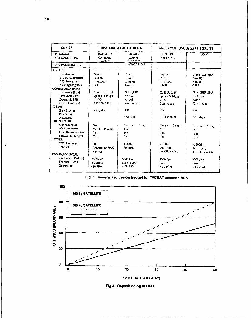
represents a 27% over design. This is mostly due toA 36 channel EHF payload was also sized. This the lighter SHF payload weight and reduced powerpayload was designed to support EHF man portable requirement. Penalties of this order of magnitudeterminals. The payload consists of 32 low data rate must be accepted to take advantage of a commoncommunications channels and 4 channels for noise bus design. Not only does commonality achievecharacterization/acquisition. The sample payload cost reductions as a result of an increasedhas a 61 beam multiple beam antenna with a nulling production buy and corresponding learning curveprocessor on the uplink. The fully autonomous leverage, but it promotes the use of standard testoperation of the processor represents the only procedures and test equipment. Payloads can bedesign area that may be pushing the state of the art. handled as black boxes and thereby, integration andThe downlink includes a 19 element MBA, a spot test times can be reduced. It is clear, however, thatantenna and an earth coverage horn. The design the more the payload weights and missionfeatures fully redundant travelling wave tube parameters diverge, the larger the penalty that mustamplifiers. Assuming there is one user per terminal be paid by using a common bus.and an average call duration of 4 minutes, thenumber of terminals that can be supported can be The surveillance and communications missions werecalculated using message switching theory. With a then used to define the more complete set of bus5% probability of call cancellation or a 20% design parameters shown in Figure 3. As expected,

3-5
these parameters vary both as function of mission vehicle until the launch can actually take place is 24and orbital parameters. In the area of Guidance, days for an Atlas II and 7 days for a Delta IL. ByNavigation and Control (GN&C) the most stringent streamlining the process, it may be possible torequirements (pointing and jitter) are dictated by the reduce this time down to 7 and 5 days respectively.electro-optical mission from GEO. This mission also Add to this the travel time to orbit and the spacecrafthas the largest communications data rate demand. checkout time once orbit has been achieved and it isThe requirement for autonomy falls under the not clear whether the GEO based satellites can begeneral heading of Command and Data Handling responsive enough using a launch on demand(C&DH) and can be up to 180 days. To achieve this, strategy to meet user requirements. On the otherit is thought that connectivity with the U.S. Global hand, for the low altitude satellites launched on aPositioning System (GPS) would be required to Taurus, it appears that, with judicious satelliteprovide ephemeris updates. The propulsion design, response times on the order of 24 to 48requirements are driven by the need for orbit hours may be possible. It should be noted thatreconstitution (on-orbit maneuvering). This will be modifying the launch vehicle alone is not sufficientdiscussed later in this paper. Finally, the bus will for rapid response. Today's spacecraft can requireneed to be protected from the natural space days or weeks of checkout after they achieve orbit.environment as a minimum. It is recognized that a If surveillance data is to be obtained in the first orbit,truly common bus design may compromise these for example, design features such as blowdownrequirements but to determine the extend of such focal plane coolers and optics contaminationcompromise will require more detailed study. avoidance systems must be incorporated.
For the GEO based satellites, an alternate means ofTwo launch strategies have been considered for providing responsiveness has been studied. In thisTACSAT application; launch on demand and launch strategy, the satellites would be launched whenon schedule. To understand the implications of available or on some predetermined schedule andthese strategies, the launch vehicles available to the stored in orbit. The satellites could be stored in aTACSAT must be examined. In the current fleet of dormant condition and activated when needed,United States launch vehicles, the medium launch thereby, minimizing satellite life degradation. Thevehicle (MLV), i.e., Delta 7925, is the one that satellites could be stored at a convenient point incomes closest to satisfying the TACSAT the GEO belt and repositioned to the area of interestrequirements. With a solid propellant kick motor, it is as the need arises. Figure 4 shows that a 600 kgcapable of placing approximately 900kg into a class satellite could be shifted up to 300 per day withgeosynchronous orbit. This represents a 40% over the expenditure of no more than 45 kg of fuel. It iscapacity for the 635 kg TACSAT described. An doubtful, however, that it several satellites areAtlas class MLV, will place approximately 1500 kg stored in this manner, there would be a requirementinto GEO allowing TACSATS to be launched two-at- for this high rate of orbital shift. It seems morea time if such a launch strategy is deemed to be reasonable to anticipate maneuvers on the order ofadvantageous. For low altitude satellite 50 per day considering that crises or conflicts do notdeployment, the Pegasus lift capability is about 400 normally occur instantaneously but rather developkg; somewhat shy for the satellite discussed in this over some period of time. Under these conditions,paper. The Taurus, which is essentially a Pegasus the 45 kg of propellant could provide 4 to 5 suchon top of a Peacekeeper first stage, appears ideally maneuvers per satellite without affecting satellite lifesuited to this application. This vehicle is, however, on orbit.still in the development stage.
In summary, this initial study has shown thatResponsiveness is a characteristic generally TACSATs can be used to augment the existingassociated with TACSATS. The capability to rapidly backbone space architecture by providing adeploy the satellite to the area in which it is needed capability that currently doesn't exist, such as tacticalis essential. When examining the responsiveness surveillance, or by adding to an existing capability,of our current launch fleet, however, the nominal such as communications, in times of crisis or conflict.time from the mating of the spacecraft to the launch In this manner, it could also be used to provide an

3-6
interim capability should one or more of the deploying and operating space assets, one thatbackbone satellites fail. In order to make the gives the user direct control and the ability to receiveconcept practical, however, the systems must be critical data in a direct and timely manner.affordable. One method of achieving suchaffordability is through maximization of commonality.It has been shown that commonality can beachieved at least on two levels; a single satellite thatcan perform more than one mission or a commonbus with interchangeable payloads. Respon-siveness, which is another key element of theTACSAT concept, can also be achieved in severalways. For low altitude satellites, rapid launch ondemand is possible while for GEO satellites, storingon orbit and on orbit repositioning appears to makemore sense. To make either of these strategieswork requires that the system has a low infantmortality, i.e., when you turn it on, it works. Finally,the system must be responsive to user demands.This means user control of the asset and directtransmission of data to the user terminal.
In conclusion, the timing is right for theconsideration of a TACSAT capability. With therecent geopolitical upheavals, the focus shifts fromthe anxiety of global nuclear war to regional, tacticalareas of conflict. Such a shift leads to increaseddemands for information and capabilities that canonly be achieved from space. Furthermore, theareas of operation, although limited in size, are likelyto be worldwide. The ability to bring assets to bearrapidly will be of paramount importance. Recentexperience in Desert Storm has attested to thissupposition. The value of space assets forsurveillance, communications, weather andnavigation was clear. System shortcomings, such asthe inability to get some data directly to the user wasalso evident. Desert Storm also demonstrated theimpact of a cooperative, coordinated, multinationaleffort. This trend is likely to continue in the futureforcing requirements to be specified on a universalrather than a national level. These commonconcerns and needs, along with the severe militaryspending cuts that are facing individual nations,provide a greater opportunity for internationalcooperation in the development and use of spacesystems. The TACSAT concept is particularlyattractive in this regard by providing the means ofacquiring incremental capability on an as neededbasis. If the degree of commonality andinterchangeability discussed in this paper can beachieved, the TACSAT can provide a new way of

Optics - 45 cm aperture
Focal - Visible and lRPlane * Wide FOV focal planeArrays . 30 x 0.501
Ff7 off-axis- High resolution focal plane
- 0.160 x0.160
- F/15 on-axis
-Pointing and - Reactionless drivesScanning -± 450 conical field of regard
- Wide area coverage in 30 swaths
Envelope - 70 x 100 x 100 cmWeight * 112 KgPower - 370 w (600 w peak)Downlink - 0.03 - 308 Mb/SData Rate (Mission dependent)
Fig 1. Multi-mission sensor
Multi- Cloud/ TacticalTheater Spectral ISpace Object Ocean Missile
Mission Surveillance Sensing Surveillance Imaging Tracking
Orbit, kmn 500 500 500 35750 35750
Spectral Various VariousBands, g.m 0.45-0.90 Commandable 0.45-0.90 Commandabie 2.7
0.4-10.0 0.45-10.0
Field of view/ 1.60 x 1.60 30 x 0.10 swath 3600 swath 180 x 18,, 30 x 301scan rate, data 2.501sec 1 .80/sec So/sec 80Isec
rate 274 Mbps 274 Mbps 20Kbps 70 Mbps 20Kbps
ContinuousRe-visit 12 Hours for one satellite -over Area 2 sec
of Interest
F11 2. Multi-mission sensor performance
3-8
ORBITS LOW-MEDIUM EARTII ORBITS GEOSYNCIIRONOUS EARTII ORBITS
MISSIONS / ELECn0.O OlIIER ELEC'I'RlO COMMPAYLOAD TYPE OI'ICAL COMM OIfICAL
___________________________ < low u) (I~. 1I1A1 lum
BUS PARAMETERS NAVIGATION
GN&CStabilization 3-axis 3-4ixs 3-axis 3-axis, dual spinS/C Pointing (deg) .5 to .01 .5 to .1 .2 to .U .5 to-02S/C litter (deg) .1 0O. ,001 .5 to.U2 .1 to .0001 .5 to.03Slewing (deg/sec) 3.0 Nonc None None
COMMUNICATIONSFrequency Band S, X. SlIF, El IF S, L, UI IF X, SI IF. -IiF S. X, SHF, EFIFDownlink Rate up to 274 Mbps 4K1bps up to 274 Mbps 10 MbpsDownlink BER < 10-6 < 10-6 <10-6 <10-6Contact with grd 2 to 12X /day h11ncimitcnt Continuous Continuous
C &DHBulk Storage 2 Gigabits No No NoProcessingAutonomy 1lt0 days I - 3 Monhs 90 days
PROPULSIONStationkeeping No Yes (+ - .10 deg) Yes (+ - 10 deg) Yes (+ - 10 deg)Alt Adjustment Yes (+- 25 nmi) No No NoOrbit Reconstitution Yes No Yes YesMomentum Mngmt Yes Yes Yes Yes
POWEREOLAve Watts 600 < 1000 < 1300 < 1000Eclipses Frequent (> 50(X) lrCtluent lnfrequent Infrequent
cycles) ( -3000 cycles) ( - 3000 cycles)ENVIRONMENTAL
Rad Dose - Rad (Si) <o500} 50(yr 2y00 / yI 20 0 0 /yrTheinal Req's Stressing Mod to low Low LowOutgassing < 50 PPM < 50 PPM < 50 PPM < 50 PPM
Fig. 3. Generalized design budget for TACSAT common BUS
100
450 kg SATELLITEso
680 kg SATELUTE
~60
404
, Ul
0 ,,
0 10 20 30 40 50
SHIFT RATE (DEG/DAY)
Fig 4. Repositioning at GEO
Discussion
Question: To meet stated requirements for area coverage,how many spacecraft will be needed, given a 9km X9km IFOV? The issue is whether the total constellationsize needed will drive costs beyond affordability.
Reply: A single satellite takes 9 X 9km snapshotsanywhere in the acquisition area. The number of areasto be imaged and the dwell time on each target area,as well as the revisit time requirements and the orbitalaltitude, will dictate the number of satellites required.Tradeoffs have not been conducted to assess affordabilityas a function of requirements, but, as you observed,the requirements must be kept under control oraffordability will be lost.

.-1-
EVOLUTION OR REVOLUTION - THE CATCH 22 OF TAC3ATs?
by
CJ. ElliottSmith System Engineering
Smith Associates Ltd
Surrey Research ParkGuildford GU2 5YP
United Kingdom
I Introduction technology and. taken with the planning delays, means that
The potential exploitation of TACSATs is limited by a spacecraft are built with obsolete components. Largevicious circle in which users do not specify reuirernents projects need large launch vehicles which, when combinedwhich they believe to be inteasible and the space irdustry with the lack of competition and the need for high
does not offer radically new solutions because it perceives reliability, means that launch is expensive-no demand. This is the Catch 22 of the title. Large projects also reqtire large payloads and justify a
iarge (and expensive) ground infrastructure. LargeThis paper aims to show some of the Fossibilities if we break payloads bring a twist of their own. The space systems areout of that vicious circle. A private civilian Earth too big to be built by a single contractor and it is necessaryobservation mission iSeaStar) is adopted as a bas,ýlire. Inordr t ilustatewha miht e pssile.miltar ,o invoke a complex (and k.xpensive) managementorder to illustrate what might be possible. military structure, One consequence of this is that it is difficult topayloads for surveillance, verification and C31 are perform optimisation trade-offs between components of thesuggested, derived from land or air based systems that either system because of the rigid contractual boundaries, Thisalready exist or are known to be under development. It results in non-optimum designs built, as argued above, withmust be appreciated that these arc not presented as proposed obsolete components, which leads to very poordesigns. merely as a kind of "existence proof" for high -performance per kilogramme. Here is the first vicious spiraperformance and low cost satellites. because poor performance T, cr kilogramme requires even
bigger payloads.
It is possible, on the basis of this "existence proof". to
explore some of the operational consequenc, of the moregeneral use of TACSATs. _ _ _ _
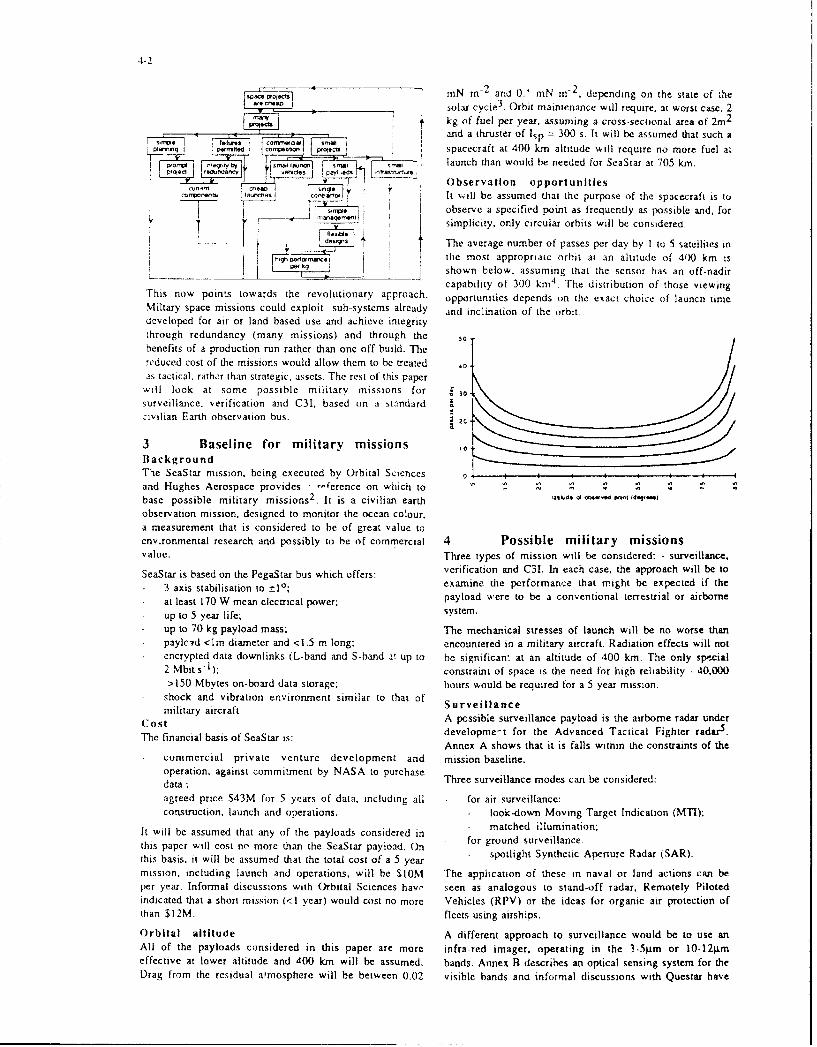
2 "Traditional" space thinking ______
There has been a development in the space proie,-s carried ,I..
out in the USA and Lurone from the early days of simple. L--
dedicated and inexpensive missions, through to the present , L _J _ 9 _•__"___
position where most missions are complex. multi-purpose__,. °,i"* ,and expensive.
This is a result of a positive feedback mechanism1 whichsystematically forces space missions to become morehIexpensive, take longer to execute and fail to satisfy the"'needs of their users. The positive feedback mechanism starts P.with the belief that space projects are expensive. The -consequence of this belief is that there will not be mary When all of these arguments are brought together, theprojects. Few projects mean that: resulting vicious spiral reinforces the opening premise:-
they must be planned carefully to get the best out of "'space projects are expensive'. Any perturbation. like athem; launch vehicle failure. causes more passes around the spiral
they must be reliable; which reinforces the premise and the costs climb further.
they need to he large to achieve a lot from each It is important to recognise that there is no malicious act in
project; this spiral, It is a consequence of reasonable decisions beingtaken at each stage of the design and planning of these
there will be little competition (nct onjy commercial projects. TBat is why revolutionary changes in thecompetition between suppliers but there is also little procedures., practices and thinking are needed to reverse theroom for competition of ideas). cost drivers.
Each of these brings consequences for the conduct of the What could happen if all of these changes in approach wereprojects. Planning causes delays. High reliability when not to occur? If it is assumed that space projects are cheap, abuilding many systems means that integrity must achieved different p<ositive feedback picture emerges, a virtuousby design This precludes the use of the latest, unproven spiral.
4-2
nmN m-2 and 0.' mN m-2. depending on the state of thesolar cycl 3. Orbit maintenance will require. at worst case. 2
, kg of fuel per year. assuming a cross-sectional area of 2m 2
l and a thruster of Isp = 300 s. It will be assumed that such aspacecraft at 400 km altitude will require no more fuel at
Sma syrx" ,, - launch than would be needed for SeaStar at 705 km.
*- C) __) d'-- Observation opportunities* w•''si i •It will be assumed that the purpose of the spacecraft is to
observe a specified point as frequently as possible and, for' (simplicity, only circular orbits will be considered.
14,The average number of passes per day by I to 5 satellites in
the most appropriate orbit at an altitude of 400 km isshown below, assuming that the sensor has an off-nadircapability of 300 km 4 . The distribution of those viewing
This now points towards the revolutionary approach. opportunities depends on the exact choice of launch timeMiltary space missions could exploit sub-systems already and inclination of the orbit.developed for air or land based use and achieve integritythrough redundancy (many missions) and through thebenefits of a production run rather than one-off build. Thereduced cost of the missions would allow them to be treated 0
as tactical, rather than strategic, assets. The rest of this paperwill look at some possible military missions for 30surveillance, verification and C31. based on a standard Icivilian Earth observation bus. 2
3 Baseline for military missions ,oBackgroundThe SeaStar mission, being executed by Orbital Sciences 0and Hughes Aerospace provides -erence on which tobase possible military missions 2
. It is a civilian earth " ' "' i'q..
observation mission, designed to monitor the ocean co!our.a measurement that is considered to be of great value toenvronrnental research and possibly to be of commercial 4 Possible military missionsvalue. Three types of mission will be considered: - surveillance,
SeaStar is based on the PegaStar bus which offers: verification and C31. In each case, the approach will be to
3 axis stabilisation to ±1'; examine the performance that might be expected if the
at least 170 W mean electrical power; payload were to be a conventional terrestrial or airborne
up to 5 year life; system.
up to 70 kg payload mass; The mechanical stresses of launch will be no worse thanpayled <lm diameter and <1.5 m long; encountered in a mili:ary aircraft. Radiation effects will notencrypted data downlinks (L-band and S-band at up to be significant at an altitude of 400 kin. The only special2 Mbit s-): constraint of space is the need for high reliability - 40.000>150 Mbytes on-board data storage; hours would be required for a 5 year mission.shock and vibration environment similar to that of Surveillancemilitary aircraftSurv•iIian e
Cost A possible surveillance payload is the airborne radar under
The financial basis of SeaStar is: developme-t for the Advanced Tactical Fighter radarS.Annex A shows that it is falls within the constraints of the
commercial private venture development and mission baseline.operation, against commitment by NASA to purchase Three surveillance modes can be considered:data ;agreed price S43M for 5 years of data. including ali for air surveillance:construction, launch and operations. look-down Moving Target Indication (M7T);
It will be assumed that any of the payloads considered in matched illumination;
this paper will cost no more than the SeaStar payload. On for ground surveillance:spotlight Synthetic Aperture Radar (SAR).
this basis, it will be assumed that the total cost of a 5 yearmission, including launch and operations, will be SIOM The application of these in naval or land actions can beper year, Informal discussions with Orbital Sciences havc" seen as analogous to stand-off radar, Remotely Pilotedindicated that a short mission (<1 year) would cost no more Vehicles (RPV) or the ideas for organic air protection ofthan $12M. fleets using airships.
Orbital altitude A different approach to surveillance would be to use anAll of the payloads considered in this paper are more infra-red imager, operating in the 3-5gtm or 10-12itmeffective at lower altitude and 400 km will be assumed, bands. Annex B describes an optical sensing system for theDrag from the residual atmosphere will be between 0.02 visible bands ano informal discussions with Questar have

4 3
indicated that art lR version of the 12- telescope is being io he air expensive optiton lli'c esr. iti should hie seen in
considered. A 256 element linevr detector array would [tice conicest 01 the orsis it eons entioitial w~ocijlartc asset,
allow imaging a strip -2-5 kin wide with - 10 in spatial tich as staind off trsiIlie alut I!i 1 i. 1 is Gto
resolution in thc 3-5ltni band. This would allow detection aprprorpriate to crinjipare dirlet.Oi I.- of I~ ii A( S Al's aridof. for example. thermal signatures on runways where aireral I sine ithes ri N ffr diffecrenti ipabi itilos hij
aircraft have taken off or the detection of hot spots on surveillance aircrafi ilulusrate tfnC stints of MOIi v tries tha
arnmoured vehicles caused by the heat of their engines. he allocated it) tactical stroflnte ntriii i C;
V erife at ion The cost of operating a survedinare air ralit I, oft tile ortrcl
Space-based verification systemis may be ul~ed ito cue of S5OIXI pei hour. Thius. the cost it 'Aisir -,et rot one
ground or overflight inspections. A systemn with moderate .%ar woutld be oItihe order of ShIMN l I,i h nis t itiis added
spatial resolution but with the flexibility to image [ti etfecirse cost ot tile talite ;rrrrrtrith;s ma iic alerrrcali
frequently and without warning might he art effective ma,, he lost due it) eneuri .i. irtr
deterrent to breaches of a treaty.Acriilaotit *tti es.tldps eOsrnin
The Optical Sysiem described in Annex H would allow 2 km nines per laant rod rtic Ire ITk 10 hirii it .1 o t ii Or cnitirni..
"sur "iaes tit any pioint to hec obtained with a spatial io- air missiles at a cost of no more than Strok for one 'erresolution of I i. rhis IS adequate for the detection oft all The Imnarcial case otr satellites is stronger if ihe operation is
antt recognition of most itypes of target,. Tihe satellite mtay required to continue tor longer thant one %ear For example,he tasked with a iisi ot points of interest andi can then A drugs interdiction support operation could use 3 satellites
autononmiously collect thle inraces anti either broadcast them ro) view Central America andi thle northern coast of South
to a local receiver or store itle m on borard indl dowrn Ioad A rICTerta more tbhan I" wtneN e ft!Ia\ i .i cost oft $300 li i.*
when next passing over headquarters. [here are several cadr.oppirortunities per darv to imlage the point oft Interest isrbi"ýtcrnuncto i itIei rt cpeei
roesatllie.res oluitionary change ,ir the opicraiisiai irtaria genrent oh
C3 1 space assets,. It rccornises; that [ACSATsir ta~ctmical4 asses. it,
Tre re are rnait wit cpcts to C 11 111tic11 ni i gt beC Addressed I'\ b iic Cfiloved and e sploriti undotOer 0"t ci 'frio of Itýt lctical
inleans of satellities . Antics C ronstiders the leasthilitt anid orinni antlers arta logo us it) kiri othen iacr cr1 a,ýcpterformnance ot a1 radar [SM sssieii t eiled: 'itdtect andi It i., ok~oncershi tihle at iM JSpice asset s ticd b onsideredidentify, litile andi CW inittiers Thle b~aseltiuc \5steml tactical unless thev wcre nmuchi cheaper to purchase andKestrel, is designcd bI,, uirborne use anti can offer o perate than than current ,trdicgt, a~sset However. it issignificant' tactical capability. particuiarlI if the satellite ix act1 IIthis approach. which tiulld leaid ito production runsSers tio itt the mult11-p~O r t ant'enna has hicgher gain ithran that o sateillites comparable r it)itise of, for csarnpie. lighter
einplottvr' in thle airbomnte erstion- airrcraft., that would c~ause the %pace assets tr be hchaper.
)ne possible use tof this sy stern woruld be tac ticai LISN [lie
s'stem %Itn board the satlilite sotitld clud itetttile cipabtlri'. Co ncIus Uio flslit) deinterlease ainrd track ratdar emnitters tinf \oitlrl ['lie argurireni has run full ncitec Thisý paper has presented
brirdcar is tack abl frssilv tcluiti rata! in approach it, the prov-isioin oft Tti(S Al\' based tin threeilertilif ration)toli tactical f ield unitus kiltult[MrnliMthoug ESMtrentisescisc s .tit es.titmate of thle elirectitin tit the thlre at 1fromt [the
,eceiver hut not its rang cc, [iIe rapril mnotion (it f(the salcItile thle risc iot an milten~ltvisc si aintard cibit.
1tti4hit ria ke it poissible tii lorcate the tIarisnititer 1w pavlitails using itiiliarv subt 55-steis.airiandattort as the satelitie passes. Tihe uise (itt two tin Moirre
satllites. has nioii been c-tns idererl lie r ihut I car% fthis I irec t comntirol a nti tasking (i tIihe satelliIte fro m lactic al
ettUlt prir idC inore ittMIiteliate intld tiihlc locatiton cit andncriter in telie tt'l
Nnr even imore potwi'rtI' svav rif tisniri rA~it satellites It' these three rules arc ailipicil. it iS .irlttet that it will be
cooiperatively woutld he tri conmpare thre little of auris al if' possible to break iout of the (arc I 2- aind achieve
intlisvidual pulses at( each satellite rather thatn to compare inexpensive riperalitonal [AC SA ,.\[ hitch convev
the characteristics of pulse trains. Tlits w iruld not horwever ignificant initltarv advantage
he %4i rthin the c apahi Iit itt a on yentinnral I airbOTIrr ESMN
sysiern like K estrel 7 A ck n ovvIed gernietits an dri-ferences
5Operational implications Acknowledgements:Thre porssibhle military itrissirris suiggestedl indictate wshit irhe authotr wourld like to tharnk ire tfollowing Irir their
Iiii t i hb e liii 5th I. lie re ire twit timpor tan iorpe rat io(nal a issi stance with [11e preparatiton 41 thlbis pialer:
trrpi licatos: International [Defence Reviesi. ('K.
it is assunmetd that thre satidt~es, ss tili he latiineheif til Gusrbial i Acenospc ( tnoraitriti. n ISA,
dlemand it fprouvitde ciover oI specific potints oI interest. Oritesar SieCc,;rratrrnhiSrtin A; S
tlie saitcllites sita Lllilr7ntriit tcil directly rirli Ilick1 Racal Radar D~efense StitsLtd. U K
units. iloiwing tile diata tha~t Is cirllcclei it) bie relayecIf Rererences:in real trite to risers antd .llotsiirgv tlie users (oi task intl Ref I FElliott C.I. "irst dlrivers Ahlv (fto comnventionalcintrilil the satellites. stitelhfres cost so much'i". Svmpsttiutin ton "Systems aiid
L~aunch on demand of a Li nstelhtitnt ott SateleIirecs iiiav seem serivices torr sttill steln. CN US. Are tc bun. June I1492.

.4-4
Ref 2 Lyon K G and M R Willard, "Ocean color remotesensing data for the 1990s", First Thematic Conference onRemote Sensing for Marine and Coastal Environments.New Orleans. Louisiana. Juite 1992.
Ref 3 Walterscheid R L, "Solar cycle effects on theupper atmosphere: implications for satellite drag". JSpacecraft 26, 6. Nov-Dec 1989. pp 439-444.
Ref 4 Wertz J R and W I Larson. "Space mission analysisand design", Kluwer Academic. 1991. ISBN 0-7923-0971-5. pp153-155.
Ref 5 Beal C and W Sweetman. "Fighter radar in the1990s". International defense Review 8/1992. pp 744-747,Ref 6 Gjessing D T. J Hjelmstad and T Lund, "A multi-frequency adaptive radar for detection and identificationof objects-. IEEE Trans AP 30, 1982, pp 351 36-5.
Ref 7 "'Minimum resolved object sizes for imagery
interpretation". STANAG 3769, Change 1.
Ref 8 "Electronic support measures equipment forrotary and fixed wing aircraft - Kestrel Mk If", Ref DRI 133Issue 3. Racal Radar Defence Systems Ltd, Chessington UK.

4-s
Annex A Radar system iSna ysis%latched illumination uses modulation schemes matched to
A. 1 Background the characteristic dimensions and resonances of the target.
It is possible to establish the feasibility in principle of This has been used to identify specific aircrait types6 . No
operating a radar on a TACSAT. by examining in outline trials have been reported of the use of this technique to
the power budgets and hence signal/noise ratio that might reject ground clutter but the selectivity shown in the
be achieved using an advanced airborne radar. The model identification trials suggests that it might be effective.
that will b,. used here is the Advanced Tactical Fighter (;round surveillance(ATF) radar currently under development. A description 0t Ground surveillance to detect and locate vehicles could bethe this developmenc programme 5 included the following carried out using spotlight SAR. Typical performancequotations: would be to form a SAR image of a single 15kmn diameter
region tcorrespondirg to the beam width) on each satelliteThe USAF has pursued X-band AESA [Active pass. A synthetic aperture of 15 km scorresponding to 2 s ofElectronically Scanned Array) technology since the illumination) would allow a SAR image of I in resolutionearly 1980s for three main reasons: power/weight ratio, to be constructed.agility and reliability. With more than a thousandtransmit/receive (TMR) modules, each capable of Current real-time SAR processors capable of this level of
generating around lOW of power. the F-22 has a peak processing have a mass and power consumption suitable for
power in the megawatt range, should that be required. airborne use and might feasibly be carried on-hoard thesatellite. Alternatively, the raw -ita Lcould be broadcast for
Ultimately, a maintenance-free life of 200)0)1 h - the ground processing.
lifetime of the aircraft . is possible.
Synthetic aperture radar tSAR) ... is not in the baseline
but the hardware can do it
A.2 Radar equationThe following assumptions w ill be made:
number of T/R modules: 4000
module power: l0W
square array, half-wave element spacing
wavelength: 30 mm
This indicates an antenna gain of -39 dB and an effectiveantenna area of - I m2 . If the spacecraft is at 400 kmnaltitude and a target of cross section Im2 is located 300 kmfrom the satellite track, then the received power will be-165 dBW. If a receiver noise figure of 5 dB and detectionthreshold of 10 dB are assumed, then the integrating timewill need to be - 3ms.
The beam width will be - 15 km at 500 km range. An areaof 500 km square will comprise of the order of 100l0resolution cells. A transmitter power of 40 kW andintegrating time of 3 nis per cell will require - 0(.1 MJ oftransmitted energy. The total energy available to thepayload is of the order of 50 MJ per orbit.
A.3 Operational modesAir surveillanceAny look-down radar suffers from ground clutter and thesystem described here will be particularly badly affectedbecause of the relatively wide beam width. Two techniquesthat might be employed to improve the detectability ofairborne targets are:
Doppler MTI;matched illumination.
Doppler MTI may be employed provided that the radar isdirected across track to detect targets with a significant"velocity component towards the satellite. The performanceof MTV with the wide beam of this radar needs further

4-6
Annex B Optical system the spacecraft to fly 64m (8Sms)
B.1 Background s is the sensitivity of the detector (480 nV )-I)
This design explores what might be achieved using existing N is the detector noise level (200 gV RMS)space or military quality subsystems to build a highresolution imaging system. The spacecraft has a space- The signal/noise ratio is thus - 1000.qualified version of a commercial telescope mounted suchthat it can be rotated about an axis aligned within - 1P of The detector pixels are approximately 25prm square. Thisthe direction of travel. A linescan imager is mounted at the requires the focal length of the optical telescope to be 10m.focus of the -lescope, aligned so that it sweeps a swath A secondary lens will be needed but this does not have toalong the d;.,ction of travel (pushbroom). be of particularly high optical quality. The type of lens
used as a x2 teleconvertor for 35mm SIR camiseras wouldThe design presented here can provide 2 km square images probably be suitable.with a spatial resolution of I m. The image region isselected by rotating the telescope for the across-track B.3 Navigation and positioning;dimension and selecting the time of recordtng for the B. aiain ad pstoigalmensiongrack d ection. the poitio of h aelditg msthbe If it is assumed that the nominal 2km square image must bealong-track direction . T he position of the satellite M ust be c n r d o h a g t p s t o i h a c u a y o 0 mdetermined to - 50 m in all three dimensions and the it is necessary to know the orientation (if the telescope to anorientation of the telescope to - I mrad in three directionsto permit the centre of the image ic he selected to an iccuracy of the order of 0.5 mrad.accuracy of-0.5 kin. Navigation information 'ws ill be derived from a GPS
receiver ,and orientation is onbtained from a star sensor.B.2 Telescope and sensorThe primaiy optical system is a space-qualified version If possible implementation ot the ('S receiver is to carrythe\ possible Qmpesenaao 12" tohes pe. Tcce ks paaetr carrythe standard Questar 12' telesc ,pc. The key arrameters 01 out the signal acquisition and processing in software withinits specification are: the on-board processing system. A baseline design using a
Sresolution: 0_38 arc sec ,inile transputer exists and would meet the requirementsf ewith a power consumption of -).SW It is likely that a morefocal length: -1.572mm
aperture: 305mm appropriate processor could he used to reduce this.
dimensions: -ain long, -350mm diameter The star sensor is mounted on the teiescope to ensure thatmass: -55kg there is a constant angle between the two. If it is assumedvibration tolerance: I Og that the properties of the star sensor are:
material: invarprice: -S200k field of view: 25'
It is understood that this telescope has b-en used on US number of stars for reliable fix: 6
military spacecraft. (hence need to use stars of 5th magnitude)spacecraft roll rate: 10 mrad s-
The baseline design is to use the Reticon RA2048J charge I- revolution every 10 minutes)coupled device (CCD) detector operating in time delay integration time: 50 msintegration (TDI) mode. It has to be configured so that itslong axis of 2048 sensors is perpendicular to the track of deteux or 5 th an dtud ist : a. Reti-on abovdetector sensitiviry and noise: ts Reticon abovethe spacecraft and the clock frequency in the transverse(short) axis of 64 detectors is synchronous with the velocity sensor aperture: 40 mm diameterof the spacecraft, detector array: 500 x 500 elements
then it will be capable of meeting the target of 0.5 mradThe signal/noise ratio of the detector, D, is given by: accuracy if it is possible to interpolate to one half of a pixel
D = r a A T s/N with a signal/noise ratio of around 70. This is considered towhere: be well within the performance of current interpolation
r is the radiance of the Ear-h. assumed to be of the algorithms.order of I00Wm 2 sr I (This figure is sufficientlycons:rvative to include large sun zenith anglesencountered at high latitudes.)
a is the area of ground magped onto one pixel of thedetector (assumed to he Im-)
A is the solid angle subtended by the telescopeaperture (0.45 x 10 2st at an altitude of 400km)
T is the integrating time. defined as the time taken for

4-7
Annex C ESM system operation. In intermittent operation with no forcedcooling. it is estimated that the average temperature of theCA Background equipment will rise by - l°C per minute. If the maximumCAnie amigt pcontinuous operation is for 10 minutes. the temperatureAn airborne ESM system might provide a suitable basis for variations will not exceed lO°C.a tactical communications or radar monitoring satellite.The baseline that will be assumed here is the Kestrel Mk H1 If this variation in temperature is not acceptable, it wouldmade by Racal 8 . This is a radar ESM, capable of detecting, be necessary to improve the thermal coupling between thedeinterleaving and tracking radar emissions between C and heat-generating elements of Kestrel and the rest of theJ band. satellite. Heat pipes might be considered or it might be
reasonablc to cutntain the Kestrcl :t a sealed andC.2 Detection capability pressurised container and to use forced air to redistributeKestrel employs a six port amplitude comparison receiver the heat.to measure signal bearing. The standard antennas give 3600coverage in azimuth. 250 coverage in elevation, a typicalpulse sensitivity of -60 dBmi and bearing accuracy of 4.50RMS. This would detect the main lobe of a 10 MW ERP C-band radar at a range of 500 km. It would also be possibleto locate the radar to an accuracy of approximately 50kmby tracking the bearing of the radar as the satellite passes.
Antennas with greater gain could be used at the cost ofsacrificing the 3600 capability. This would be more easilyachieved at higher frequencies and it might be appropriateto replace the Band 3 antenna (I to J band) with a multiplefeed horn and reflector. A reflector of the order of 5(X) mmin diameter might be expected to give 20 dB improvementin sensitivity and a factor of 10 improvement in bearingaccuracy but would not add greatly to the mass or cost ofthe system. This would allow the system to detect sidelobesof pulse radars and to locate them to an accuracy ofapproximately 5 kin.
Deinterleaving and tracking of repetitive pulse trains andidentification of emitters is strongly dependent onfrequency measurement. The worst case doppler shift causedby the satellite motion will be - 1 MHz and hence withinthe frequency resolution of the receiver.
C3 Mechanical and electricalconstraints
The three main building blocks of Kestrel. other than theantennas and receivers, are a parameter measurement unit(PMU). a data processor unit (DPU) and a man-machineinterface (MMI). The PMU would need to be on-board thesatellite, the MMI is clearly on the ground and thefunctions of the DPU could be distributed between thesatellite and the ground. There would be merit inmaximising the fraction that is on-board the satellitebecause it is likely that there would be many users for onesatellite, each of whom would require the ground-basedelements of the DPU.
Kestrel is specified to meet the military temperature rangeand its vibration and acceleration tolerances are adequatefor a PegaStar vehicle at launch. The total mass of Kestrel isapproximately 50 kg and the power consumption,excluding cooling but assuming that all of the DPUfunctions are included, is approximately 500 W.
If it is assumed that the system is operational for - 10minutes per orbit, the average power consumption is - 55W. within the PegaStar capability. In continuous operation.Kestrel requires forced air c.ooling for continuous

6-1
TACSAT Ground Control and Data Determination of technical and costCollection drivers influencing the form and cost
of ground installation and logisticby issuesC.G. Cochrane Integration of TACSAT facilities andMaa CcrconiS e Uservices with other communicationsand surveillance systems available to
Anchorage Road the Tactical CommanderPortsmouth
Hsmpshire P03 5PU - Investigation of techniques toUnited Kingdom minimise the ground control and datae Kcollection overhead
Abstract
This paper will address the concept of a Introductionsatellite based system serving the needs oftactical users for direct access to All TACSAT Systems are designed tocommunications and various forms of provide a Tactical Commander with shortsurveillance. Such a system must take term operational data in addition to thataccount of the most effective methods for available via strategic resources. Thisdeployment and maintenance during its paper discusses the interfaces between theintended period of operation, space and ground segments of such
systems. Because there is such varietyIn terms of the mission need the Tactical amongst the various TACSAT systemsSatellite System (TACSAT) is required to concepts, it is only possible in a briefprovide the services for tactical users over paper such as this, to discuss thea relatively small region of maybe some ground/space interface in general terms.1000 - 2000 km diameter. Also the Nevertheless offering a generalisedconcept is likely to involve relatively short structure around which specific conceptsperiods of operation of about 3 to 6 can be detailed is thought to be useful,months for a typical oneration scenario, especially where the concepts are unlikeThe paper therefore addresses a system those of other types of space system thatconcept in which the emphasis is placed designers may be more familiar with. Theon reducing the scale of the logistics paper therefore focuses on TACSATinvolved in the deployment of TACSAT system concepts that are not like classicalelements and simplifying the ground geosynchronous or sunsynchronousoperations and facilities necessary for the missions.users to gain access to the servicesprovided. Mission Definitions
The paper will address a number of issues For tactical operations any systemwhich arise such as: employed must be able to support the
mobility requirement and operate from- The need for 'launch on demand' unprepared and unsurveyed sites.
Communications in difficult terrain, suchThe possibility of launches being as mountainous regions, coupled with thedirectly under the control of the area need to co-ordinate ground, air and seacommander forces, presents a complex array of tactical
communication needs and information- Operating concepts for TACSATs, exchange requirements in a variety of
comparing the approach of launch- forms, particularly for an extensivevia-residual-mass as part of a larger tactical theatre of operation.mission, not dedicated to theTACSAT mission with the approach Tactical Imaging missions will beof dedicated, launch-on-demand. targetted on small, mobile platforms (eg
aircraft and tanks) as well as other keyIdentification of information flow targets (eg bridges, harbours). Multiplerequirements for TACSAT integrity sensors will be most helpful in penetratingand status evaluation and for camoflage of these targets. For Tacticalsurveillance data recovery Communications Systems, voice and data

communications, point to point, point to large spacecraft. "Spare" transponder(s)multipoint and netted arrangements may on such under-utilised strategic comsatsbe all required. The End Users may wish can then be operated as a virtualto call upon any or all of these services at TACSAT. Finally, it is sometimes theany time. In the tactical situation the case that "spare" launcher payloadunpredictability of the operational capacity into polar orbit becomesenvironment dictates that available because spacecraft designcommunications must be instantly constraints were too conservative for theavailable, reliable and trustworthy (in actual launcher performance achieved interms of a low probability of detection), a parallel development, and smallhave a high probability of timely TACSATs can be launched into similarconnection, and have an appropriate level polar orbits with this spare capacity. In allof information security, these cases the ground/space interface is
similar to, if not identical to, the parentIt is evident that the introduction of system. In some further cases, verycomplex procedures for terminal similar mission concepts are chosen foroperation, access constraints and rules purely tactical reasons. However, inrequiring a high degree of user skill to general, different mission concepts tendunderstand and implement will detract to be favoured because of the tacticalfrom the usefulness of the system as military requirements for TACSATperceived by the tactical user community. systems, for example:
TACSAT systems can be classified aspro-iding either image data derived from Flexibility under unsophisticated,spaceborne sensors or relay local controlcommunications channels between siteson the ground, or both. Classically these Low costrequirements are met by standardisedsystems architecture as follows: Minimum revisit times
Image Data - High resolution, Localized area of interestSun-synchronous,polar, circular Surprise
- Geostationary Secrecy
Communications - Geostationary but, most of all.
As has already been stated, it is not Ease of use.particularly useful here to analyse theground/space interface within such Other papers in this series illustratearchitectures, beyond stating that instances of this tendency. Here, a typicalTACSAT applications in similar "novel TACSAT" mission may bearchitectures are possible, principally summarised as:because of excess capacity becomingavailable for tactical purposes withinstrategic systems. For example, "spare" Intermediate orbit inclination,capacity sometimes becomes available optimised for target area coverage.when a spacecraft suffers a partial failureand can no longer meet the full strategic Low altitude, for maximum resolutionrequirement. When it is replaced by a and/or link margins.new spacecraft of the standard design, thedegraded spacecraft can then be operated Elliptical orbit, minimisingas a TACSAT. In another case, a geodynamic drag.standardised design of geosynchronoussatellite has been deployed to three (or Highly. manoeuvrable spacecraft tomore) stations in the geosynchronous arc maintain orbit alignment with respectto provide a global system but strategic to the target area.communications requirements on one (ormore) of the stations do not call for such a Pre-programmed payload operation.

Ground Control military staff and cypher distributionchannels will be preferred For accurate
During the full novel TACSAT mission early orbit determination, these rangingthere will be the following, distinctly stations would be on a long (> 1000 km)different, phases of operation. baseline and must pass ranping data sets
bv communications links to a CentralLaunch Preparation Phase Control facility equipped to compute the
initial orbit. It will be convenient toIt is possible that there will be a choice of arrange for this Centre to also computeLaunch Vehicle configuration. For each, necessary manoeuvres, predict thethere will be a complex trade-off between subsequent orbit evolution and, mostorbit parameters (especially orbit probably, execute the manoeuvreinclination), payload mass (or sequence in a manner consistent with anyfunctionality) and target area revisit requirements for payload deploymentuperiodicity. There will also be a complex activation/calibration. To effect thetrade-off for the phasing of any particular manoeuvre/activation sequence, Tracking,orbit between spacecraft constraints (eg Telemetry and Command (TT and C)sun angle at injection), operational access would have to be provided viacoverage requirements and spacecraft fuel several, well-distributed Ground Stationsconsumption during orbital manoeuvres. if this phase is to be completed withThere may be a military requirement to minimum delay. In short, this entiredeceive a sophisticated enemy, able to phase could be under the control of theidentify and track novel TACSAT launch site, provided with support from alaunches, as to the nature of the intended network of appropriately equippedtactical support, especially phasing over Ground Stations.the target area. Finally, there may be arequirement to defend the TACSAT However, in view of the militarysystem against jamming sensitivity of TACSAT missions, it is
more likely that all Ranging, Telemetry,The trade-offs must be resolved and the Manoeuvre Computation andlauncher/spacecraft configuration Telecommand functions would befinalised (including programming of exercised by a suitably equipped andon-board computers) early in the Tactical military-staffed Facility. For reasons ofDeployment when the Tactical Staff will compatibility with Launch Site andhave many other pressures to finalise back-up orbital support, TT and Cdeployment plans and logistic support. functions could be conducted at S-BandHowever, since it cannot be assumed that using the Space Ground Link Systemthese staff will be familiar with spacecraft (SGLS) standard, but with encryptionoperational constraints and speedy enabled shortlv after successful injectiondecision making may be of the essence, into initial orbit. Ranging, Telemetry andprevious in-depth training in system Telecommand functions could beoperation will be a pre-requisite of exercised by a 19 m S-Band Telemetry &successful TACSAT operations. Command Station (TCS), supplemented
by relatively small (3 m) S-Band terminalsLaunch and Early Operations (LEOPS) co-located with selected permanentPhase Ground Stations. Alternatively, the entire
TT and C support could be exercisedLaunch services would be provided by a within the X-Band channel allocations forspecialist supplier requiring minimum Milsatcom and Earth Resource Downlinkinteraction with the Tactical Users. The channels. In either case, TT and Cboosted ascent and spacecraft separation baseband connectivity during the periodswill be pre-programmed. However, of TACSAT visibility must be provided.determination of the initial orbit by for example via orderwire channelsranging during first apogee will be within permanent communicationsnecessary from appropriately located and accesses.equipped ground stations. Note that thespacecraft ranging transponders may wellneed to be protected by encrypters fromranging, and/or from jamming, by enemyground stations: hence digital ranging,

6-4
TACSAT Operations Phase Automated Library of FlightOperations Control Plans,
The TACSAT system is seenin this paper Planning including Anomalyas supplementing strategic C-I resources, Contingency Plans.particularly where communicationsrequirements peak or imaging data are Computer Assisted Executes actualneeded at short notice. The opportunities Operations control via Trackingto use TACSATS to best effect can Stations.therefore only be recognised locally andshould put into effect by a local Control Adaptive Training Creates andCentre. evaluates training
sessions.The Control Centre must be able to assessthe effects of orbital manoeuvres, execute Network Control is also required in themanoeuvres promptly and quickly confirm case of a TACSAT communicationsthe achieved new orbit. As has already mission. It can be assumed that thebeen said, speedy and accurate orbit communications transponder will bedetermination can only be achieved with accessed only by in-Theatre forcelong, ie out-of-Theatre, baselines, elements, using locally-assigned cyphers.Certainly for imaging missions, perigee In order to provide communicationswill be over the tactical theatre; for services compatible with the needs ofcommunications missions this may also be tactical End Users, the way in which thetrue. network is managed and user access is
granted and controlled must involve aThe out-of-Theatre character of the minimum of "overhead" workloadcontrol function for some missions is imposed on the End User. This can rangereinforced by the need to manoeuvre near from avoiding the need to point theapogee, where manoeuvre fuel usage is antenna on his terminal precisely, to theminimised and visibility to ground stations simplicity of operation of the equipment,is maximised. The Control Centre may to a means of establishing user confidencealso have to call on spacecraft equipment in the integrity of the system, and to itsdesigners and test configurations to ability to provide the services required.resolve spacecraft performance Optimum use of the TACSAT capacityanomalies. All of this tends to suggest will be most easily achieved by a mixturethat the responsibility for TACSAT of frequency assignment and timelineControl could be assigned to a Military planning issued by in-Theatre signalsSpacecraft Control Centre supported by a staff. Somr types of TACSATglobal tracking network but with an store-and-forward communicationsexcellent co-ordination interface to mission will require quite complexin-Theatre tactical operations staff. This space/ground protocols which must belatter requirement could be met by transparent to the End User. Someassignment of several specialists (with classes of TACSAT will provide imagerrecent spacecraft operations experience) or transponder configuration options thatto provide a 24-hour service at the are selectable by $round command. TheTactical HQ. The Control Centre used in-Theatre specialist TACSAT operationsduring the earlier Phases could be used to staff will be best equipped to make theexecute spacecraft control. However, a appropriate option selections, which couldknowledge-based system located be implemented either by a localin-Theatre is likely to provide faster telecommand uplink or by a centralisedresponse and more consistent operations. Control Centre. In the case of in-Theatre
jamming attacks, the former is likely toThis could be automated to minimise the provide a far more successful ECCMnumber of operations staff and provide response than the latter, provided it canconsistency during 24-hour operations. It counter any enemy jamming of thewould consist of the following elements: telecommand uplink.
Automated Mission Builds timeline The final stage of the TACSAT supportPlanning options will be disposal of the spacecraft, either
into a higher parking orbit or a burn-upduring re-entry. Once the in-Theatre

authorities have confirmed that TACSAT adequate operations and planning tools.support is no longer required, they need Both must depend on comprehensivehave no further involvement in the mission simulations for the Launchmanoeuvre sequence. At this stage Preparation and TACSAT Operationsexecution and monitoring of the Phases.TACSAT disposal could be turned overto a central Control Centre.
ConclusionData Collection
Clasically, Tactical Commanders haveModem spaceborne imagers produce very succeeded where they have made best usewide bandwidth data rates which quickly of the time available before tacticalsaturate available spaceborne storage deployment and thoroughly prepared todevices. Hence direct-to-Theatre undertake the type of operation to whichdownlinking is very attractive for small they were actually assigned. The greatTACSAT missions where data timeliness advantage of TACSATS is that they areis of the essence. These downlinks must, very flexible so it is not necessary to detailfor obvious reasons, be encrypted. in advance the type of Tactical supportBecause of the very high burst rates, required beyond a broad characterisation.spread spectrum downlink jamming However considerable expertise isprotection is not practicable; the onlv required to op'ýrate any Satellite systemfeasible protection methods are Downlink and any TACSAT Mission is likely to failUser Terminal (DUT) location and unless an adequate control system isminimisation of DUT antenna sidelobes. created and worked up to a high state ofSome on-board storage buffers would readiness before the Tactical situationallow greater flexibility in the deployment, develops. An automated knowledge-and reduce the numbers, of in-Theatre based system, including appropriateDUTs. These DUTs must be connected simulation, will be essential to the successby telecommunications links of various of TACSAT support, which in turn iskinds to End Users. On-board likely to be decisive on future tacticalpreprocessing can be used to reduce the battlefields.downlink bandwidth and reduce thecomplexity of the in-Theatre imageprocessing functions. However, someon-ground processing, including fusion STATEMENT OF RESPONSIBILTYwith other data sets, will be an essentialelement of the image assessment chain. Any views expressed are those of the
author(s) and do not necessarily representIn the reverse direction, the flow of those of HM Government.information from the End Users for targetselection must converge on at least oneTelecommand Uplink facility. Instrumentsettling times dictate that, for efficient useduring each perigee, these telecommandsmust be uplinked out-of-Theatre duringapogee.
Simulation
From the above discussion it is clear thatdeployment of a TACSAT system is acomplex undertaking requiringwell-trained operators and well-briefedoperations staff. Although the classicmilitary process of reducing complexitydown to the minimum number ofStandard Operating Procedures (SOPs)will no doubt be applied, this must becomplemented by realistic training for allspecialist staff and the provision of

6-6
LuLUAc
00%A
z
I.-0
00zz
zz
LL.Lu
w 0
zLU t
!5 LU
0V
00
I -
Cl)F
II-
00
< 14
U)Ua. LU
C)-
'AA

TACSAT-SPACECRAFT BUS CONCEPT AND DESIGN:APPLICATION OF A MULTIMISSION BUS FOR TACSAT IN LEO
by
Georges RichardMatra Marconi
Espace/ Direction des Programmes MilitairesZ.I. du Palays-Rue des Cosmonautes
31077 ToulouseFrance
FROMI A FEW LARGE SOPHISTICATED - then for a given budget, number ofSATELLITES ... operational units decreases
c - a limited number of spacecrafts leads topusch for mission optimisation with :
- an increase of in orbit life timne and reliabilityBefore describing the way, a low earth orbit i
multimission Bus for tactical application isdesigned, it is convenient to analyse in some - the need to group several missions on the
details what is a tactical satellite as far as such same spacecraft
satellites are very often associated with the -technical sophisticationnotion of cheap small satellites.
conservative approach including meticulousdevelopment and complex vcrifications
For 30 years the size, the mass. the complexity, - no risk approach. as the unit cost of eachand the cost of the satellites have been satellite is such a high stakeincreasing. Space programmes, especially in the
defence area, tend to use heaw and costlysatcllites in a too small number of specimens All these points lead to unit cost increase andcompared with the needs of users. they have bring back to stage a in the inflationist spiral.
then to continuously monitor priority conflictssuch as :budgetary conflicts to decide whichprogramme has priority, operational use ..,TO CONSTELLATIONS OF NUMEROUSconflicts when programming the missions of so CHEAP LIGIITSATSfew spacecrafts.
To break this spiral, some experts suggcst aIn the today context of budgetary constraints, "Smart small cheap lightsats" concept. Theirraising a gain is the well known syndrome "one main idea is to drastically decrease the unit costaircraft. one tank, one satellite as unique future of the spacecraft in orbit, this cost including theequipment for defence", satellite recurring cost itself, the launch cost and
the ground segment and operations costs.
The spacecrafts number limitation is theconsequence of an inflationist spiral which can This concept is consistent with a systembe described in three stages architecture using constellations of numerous
a - unit cost increases satellites of limited in orbit life time and low

s 2
reliability periormances, both of these concept is technically relevant in fulfiling thecharacteristics should, in theory, reduce strongly requirements of a given set of missions.the recurring costs of the spacecrafts. However, with the payload beeing shared
between a large number of small satellites, we
Such a concept is reinforced by advances in can assume that the total in orbit mass of these
technology in *he fields of performances and satellites to fulfil a mission would be obviously
miniaturisation : these advances are made larger than the total mass when the classical
possible by the research and development approach using heavy satellites is followed ;programmes led by DARPA and SDIO,these grouping different payloads or a single satellite
programmes are also based on high always saves mass.
technologies developped out of the spatial area.For example: As a consequence, a "Smart small cheap
lightsats" approach using satellites with an in-digital computers orbit life time 5 to 10 times shorter than in a
classical approach leads to place in orbit a total
- mass memory mass more than ten times heavier than the total
- ASIC with availability of dedicated algorithmes mass necessary to fulfil the same mission on afor digital processing big satellite.
- silicium and Ga As microelectronics facilitieswhere heavy investments for civilian or military For a mission on a given period of time Fig. 1airborne applications give new olpportunities for shows the evolution of the launch cost andspace applications such as : optical detectors, satellites costs with respect to the targetted inradiofrcquency MIMIC which are usuful to orbit life time for each satellite of thedesign phase array antennas for communication constellation.satellites or s,.,actic aperture radarinstruments.
- etc ... For a constant launch unit cost, the total launchcost (curve 1) is the inverse ratio of the in orbitlife tinc.
The potential advantages of such a "Smart smallcheap lightsats" concept are very attractive forthe users, this is particulary true for tactical The satellites total cost (curve 2) is consistentapplications in low earth orbit with the Smart small cheap lightsats'
approach : when the in orbit life time decreases,you save more money from the satellites unit
-repetitivity of the passes cost decrease than you loose from the increasein the number of required satellites, the net
- flexibility in the choice of the orbit pa'aimeters result is that the total cost decreases. (this
- share of risks of failure of each spacecraft and conclusion is less valid for a very long in orbitlower %ulnerability of the overall system life time and is no more valid for a very short
- flexibility in the '%ay to use the system. In orbit one).
means are fitted with the level of crisis with acontinuum from str-tegic use to tactical use With a launch unit cost of the same order of
- dedicated satellite for a given mission magnitude than each satellite unit cost (curvesin continuous line) the overall cost (curve 3)
- satellite programing and use decentralized to decreases when life in orbit increases. Aton the field theater users evidence th-. optimum is to improve the
- etc... (list not exhaustive) reliability and the in orbit life time: it is the
present trend.
At this point we will not discuss if such a A "Smart small cheap lightsats" approach would

only become pertinent if very cheap launch costs [ES FOR THE BUS DESIGNare proposed (curves in dotted line).
A coherent way to decrease the launch costs isto aim for a "Smart small cheap lightlauncher" Due to the reduced number of satellites for aconcept cutting down the launch cost fo. t Kg in given application, the reduction of the
orbit by at least ten times. spacecraft recurrent unit cost is no more the keyelement to reduce the overall cost.The costreduction has to be more focusscd on its non
Unfortunately the cost per Kg in orbit for reccuring part than on the recurring one.present or near term heavy launchers is very farfrom this goal, for small launchers of thePEGASUS class with a cost per Kg 2 to 3 times As a consequence, mass production savings willgreater than the one of the ARIANE V/TITAN not be gained from only one mission, but willclass heavy launchers it becomes more and have to be gained from a multimissionmore difficult to achieve, approach.
A WISER APPROACH Assuming that the smaill satellites potential
applications arc not ained at replacing the
present heavy and complex satcllitcs systems,
With the lack of emergence of vcry cheap the overall performances required from the
launchers, constellations of numerous cheap spacecraft BUS would be moderate. This is verylightsats with short in orbit lifo- lime are neither convenient with a modular multimission BUS
for the short term nor for the medium tern. concept based on :
To open the way to new missions -especially n - standard payload interfaces
the tactical area - the only driving force of oversized ressourccs for each module (for easeinterest is, for a given mission, a moderate the sake of a good standardization)overall cost. consistent with the performancesoffered for a set of sufficiently high priority - flexible aceomodation of the different module•objectives, on the BUS allowing on request modules
addition
In other words. the todav raisinv of Fig. 2 showks the modular mulimission BUStechi ological breakthrough in performance and concept designed jointly by MATRAconceptsaio wilgne jbite use illATRAs ominiaturisation will be used in two ways to MARCONI SPACE and its north american
partner FAIRCHItLD-
I - enhance again the p~resent lperfOrmances of In order to reach some non recurrent cost masslarge satellites which will remain heavy and production savings through several applications.sophisticated. This is typically the case in the it is possible to add to this modular approach ar- )nnaissance feld w%'here users Put new development plan concept based oncontinouslv more : tringent requirements. concurrent engineering.
2- open the door to new missions, able to satisfy Fig 3 shows the iOg-ic of SYSTEMAeconomically new needs through the use of SYSTEMA is a concurrent enisincering satellitespatial means. New missions types will be design tool develol dcd by MATRA MARCONIoffered while reducing the mass. the size and SPACE. At the center a common data basethe overall co.st of satellite in orbit. This appears contains the current configutation of theespecially pertinent for tactical missions, satellite becing desibiied. At the periphery

specific tools for each main areas of engineering the launch site. A programme conducted in a
design are shown. They can be concurrently call very short time for a very competitive cost.
on demand by the different experts working inparallel for trade off or validation on different
fields : electrical, thermal, mechanical , orbit CONCLUSIONenzironment, attitude and orbit control,
dynamic , propulsion, payload accomodation,mission, satellite programmation, etc .The approch presented above is far from a
revolution. It is only an evolution.
Presently, SYSTEMA is used primarily in thefirst part of the development process (fig 4), To be efficient such concurrent engineeringfrom phase A proposals, mission and satellite tools need to be validated and calibrated bylayout trade-offs to the end of phase B with
detaledsan.-Iite esin otimsatin ad u toreference to the data gathered during previousdetailed satellite design optimisation and up todelomntetorurginrbtoioig
propsal fo a haseC ativty.development tests or during in orbit monitoringproposals for a phase C activity, of operational spacccrafts. In that sense such an
approach capitalises the whole experience
If additional risks caused by eventual flaws or acquired by MATRA MARCONI SPACEthrough previous or current lo~w earth orbit
bugs in numerical simulations are accepted -
these risks are assumed to be affordable for programmes : SPOT 1,2.3 - ERS 1 and 2.HELLOS - SPOT 4 and Polar Platform.
small tactical satellites with not very.
sophisticated missions -, phase C validation bymeans of such concurrent engineering only tools The SYSTEMA use built-in flexibility gives thewould save not only the major portion of theenvionmntaltess cots theralvacum, unopportunity to quickly update a current designenvironmental tests costs (thermal, vacuum, sun, and thus allows to follow evolutions of
vibrations) but also would reduce the schedule a nd or a cl o mo a new availabletechnologies or accomodate a newly available
induced costs. equipment.
SYSTEMA allows a short reaction time and a
Such an approach has demonstrated its quick accomodation on the satellite as soon asefficiency through the SSOT programme (fig 5). emerging requirements are formulated by theS80T is a microsatellite launched this summer users.as a companion of TOPEX - POSEIDON
SPACECRAFT on ARIANE. S80T hasbe:iefited from an intensive use of SYSTEMIA lllustrations tor this Nection appear immediatehl
from the first stage of design to the delivery at after the French translation.,

S-5
IDES GROS SATELLITES EN NOMBRE Iregroupement de plusicurs missions stir tne
LIMITE... scu! satellite
.complexification technique
Avant d'aborder la fa~on de concevoir une .m~trhodes de d~veloppement conservatricesplate-forme multimission pour des base de v~rifications complexes et minutieusesapplications tactiques en orbite basse, ii est. cudepnr esiqe evt1'juutile d'analyser de plus pr~s la notion de qerel eprdendre des~ ristaies de cant lenesatellites tactiques qui est souvent associde satelliteaujourd'hui 1 l'idde de petits satellites paschers.
ce qtii cntraine l'augmentation dti coc~t
Depuis 30 ans on constate que la taille, la unitaire et lotis ramene au Point "a "..etc
masse, la complexit6 et donc le coca dessatellites croissent. Les programmes spatiaux .. AUX CONSTELLATIONS DE PETITSet plus particuli~rement dans le domaine de la SATELLITES BON MARCHIEdefense tendent ý utiliser des satellites lourdset cofitewc: en nombre jugd ntkessairement
troplimte pr ds itillateus qi doentPour sortir de cette spirale certains proposentg6rer en permanence des conflits de prioritd:ueapoh Satsr. ha ihsasconllits budgdtaires pour decider quel dotine approch "Smarte esent. chea lihstatdeprogramme mener en prioritd mais aussi domnte dacratistiqu etile esse n itielees deconflits de priorite en utilisation daeiminer da ueen obtc ot Iccomt unitaire cduopdrationnelle pour programmer l'emploi des -tre d satellienorite, cc co~t compreanc et, lecot
moyens.coat du maintien ýi poste par Ie centre decontrule.
Dans le contexte actuel des compre sionsbudgdtaires on voit ainsi renaitre le syndromebien connu 1 AVION I CHAR ISATELLITE comme seule dotation A terme Cette approche est cohcdrcnte avec tinepour Ia defense. architecture syst~me basde stir des
constellations de nombreux satellites dont Iadurde de vie en orbite est !imitde et dont Ia
Cette limitation du nombre de satellites est Ia fiabilitd petit 8tre plus faible (droit A Iacons~qtience d'une spirale inflationniste que panne), ce qui en thdorie permet de r~duireV'on petit ddcrire en trois dtapes : fortement les cofits r~currents des satellites.
a - ugmntaiondu c~t nitireUne telle approche se trouve confortte par lesa - ugmntaiondu c~t nitireavancdes technologiques en performances et
b - A budget constant diminution du nombre miniaturisation qui alimentent aujourd'hui led'exemplaires opdrationnels spatial au travers des programmes de
c - Zi faible nombre d'exemplaires optimisation Recherche et Ddveloppement mends par lade la issionDARPA oti la SDIO, mnais egalemencrt parde I mision:synergie avec Ia haute technologie dcdveloppde
pour des applications autres que spatiales.
recherche d'une grande durde de vie et d'une Citons :
haute fiabilitd - le doniaine du calcul digital
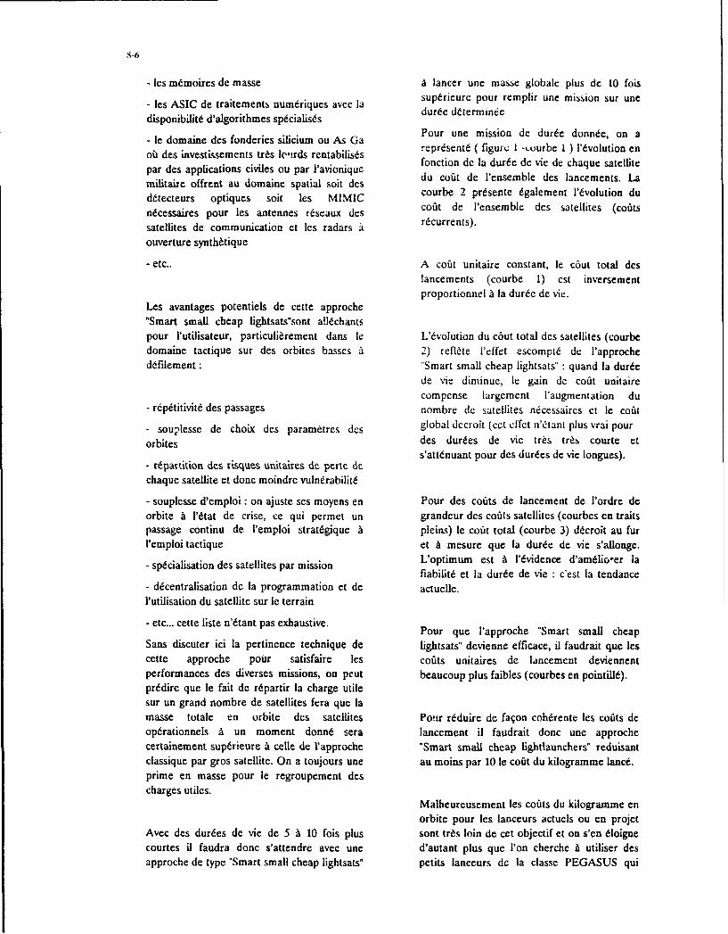
-les m6moires de masse A lancer une masse globale plus do 10 foislsAIdetraitements nudiusae asupdrieure pour remplir uric mission sur uric
disponibilitd d'algorithmes spdcialistds dredtri
le drnane es orierie siicirn u A GaPour une mission de dur~e donn~e, on a
oii des investissements tr~s loc,!rds rentabilisds fopsnctinde (a diUlte de viue Ie cha u saltellitepar des applications civiles cii par l'avionique du cton o a e P deseb desved hancemsaellts. e
militaire offrent au domnaine spatial soil dcsducadeVnmb eslcmnt.Ld~tecteurs optiques soit les, MIMIC courbe 2 presente dgalement l'tvolution du
n~cessaires pour les antennes rdseaux des coazt de l'ensemble des satellites (coatssatellites de communication et les. radars Ardcurrents).
ouverture synth~tique
-etc.. A coait unitaire constant, le c~iut tota deslancements, (courbe 1) est inversementproportionnel A la durdc de vie.
Les avantages potentiels de cette approche"Smart small cheap ligiitsats'sont alldchantspour I'utilisateur, particufi~rement dans le L'6volution du c6ut total des satellites (courbedomaine tactique sur des orbites basses A2) reflte 1'efl'et escomptd de l'approcheddrilement: "Smart small cheap lightsats" : quand la durde
de vie diminue, le gain de coat unitairecompense largement I'augmentation dui
- rdpdtitivitd des passages nombre de satellites ndcessaircs et le coat
- souplesse de choix des param~tres des global dccroit (cet cffet ii'itanh plus vrai pourorbites des durdes de vie tr~s tr~s courte et
- repartition des risques unitaires, de perte de satnatpu e udsd i oge)
chaque satellite et done moindre vulnerabilitd
- souplesse d'emploi : on ajuste ses moyens en Pour des coaxts de lancement de l'ordre doorbite a I'dtat de crise, ce qui permet un grandeur des coats satellites (courbes en traitspassage continu de l'emploi stratdgique A pleins) te coat total (courbe 3) dt~croit au furI'emploi tactique et A mesure. quo la durde de vie s'allonge.
-spdcialisation des satellites par mission L'optimumn est A l'dvidence d'amdlio-'er lafiabihitd et la durde de vie :c'est la tendance
-d~centralisation de la programmation et de actuelle.l'utjlisation du satellite sur le terrain
- etc... cette lisle n'dtant pas exhaustive. Pour que l'approche "Smart small cheapSans discuter ici la pertinence technique de fightsats" devienne efficace, il faudrait que lescette approche pour satisfaire les coats unitaires de lancement deviennentperformances des diverses missions, on peut beaucoup plus faibles (courbes en pointill).pr~dire que le fait de. rdpartir la charge utilesur un grand nombre de satellites fera que lamasse totale en orbite des satellites Pour r~cduire de fa~on cohdrente les coats deopdrationnels A un moment donn6 sera lancement il faudrait doric mne approchecerlainement supdrieure a celle de Vapproche "Smart small cheap lightlaunchers" reduisantclassique par gros satellite. On a toujours une au momns par 10 le coat du kilogramnme Ianct.prime en masse pour le regroupeinent descharges utiles.
Maiheureusement les coats du kilogramme enorbite pour les lanceurs actucls ou en projet
Avec des durdes de vie de 5 A 10 fois plus sont tr~s. loin de cet objectif et on s'en dloignecourtes Ul faudra done s'attendre avec une d'autant plus que P'on cherche A utiliser desapproche de type "Smart small cheap lightsats" petits lanceurs de ]a classe PEGASUS qui

8-7
affichent un cofit au kilo de 2 A 3 fois reduction des coOtis doit porter plus sur le nonsupdrieur A celui des tr~s gros lanceurs de la r~current que sur le recurrent.classe ARIANE V ou TITAN.
En corollaire, l'effet de strie n'ttant plusUNE APPROCHE PLUS RAISONNABLE suffisant sur une seule mission, les r6ducitions
de cofit lies aux effets d'dchelle doivents'obtenir en jouant sur l'aspect rnultimission.
Faute de voir dmerger des lanceurs A1 trts bascofit, les constellations de nombreux petitsAupadeprfmncs n lmsr osontelites pousl court naipurle ayden dermie.n les applications envisagdes sur petits satellites
sontni ourle our ni ourle oye teme.n'auront pas la pr6tention de remplacer lessyst~mcs actuels utilisant des satellites lourds
Le seul crit~re rdellement dimentionnant Pour et complexes, l'enveloppe des performancesvoir dmerger de nouvelles missions et demanddes A ]a plate-forme doit 8&re plusparticuliarement dans; le dornaine tactique moddrde. Ccci rend particuliremcntsera plus certainement d'avoir un cofit global pertinente une approche modulaire mettant ende possession raisonnable pour des oeuvre:performances jugdes suffisamment prioritaires
- des interfaces standards avec la charge utileDit encore autrement, les avancdes . une surabondance des ressources pourtechnologiques en performance et chaque module autorisant une bonneminiaturisation que l'on voit poindre standardisationaujourd'hui poussent dans deux: voies:
- un amdnagement souple favorisant l'ajout demodules compidmentaires, A la demande.
- Amdliorer encore les performances actuellesdes gros satellites qui resteront lourds ctcomplexes. C'est typiquement le domaine oi Cette approche madulaire est reprdsentdeles besoins exprimds par les utilisateurs vont typiquement par les concepts de BUStoujours croissant. Par exemmle la MULTIMISSION dtudids conjointement parreconnaissance. MATRA MARCONI SPACE ct notre
partenaire nord amdricain FAIRCHILD(figure 2).
- Ouvrir la voie vers de nouivellcs missionspour satisfaire dconomiquement de nouveauxbesoins au moyen de syst~mes spatiaux, en Toujours dans le but de rechercher un effetoffrant des performances nouvelles et en d'dchelle entre plusieurs applications pourrfiduisant ]a masse, la taille et donc le cofit de r~duire les co~ts non rdcurrents, il y a lieu
possession en orbite d'un satellite. Ceci est d'adjoindre A cette approche ML.-ilaire uneparticulifirement pertinent pour des nouvelle conception du plan de
applications tactiques. d~veloppernent basde sur une ingenierieint6grde.
CONSEQUENCES SUR LA CONCEPTIONDES PLATES-FORMES jLa figure 3 prdsente Ia logique de l'outil
SYSTEMA utilisd A MATRA MARCONISPACE en ingenierie satellite.
Compte tenu du nombre rn~cessaicmcnt rdduitde satellites pour une application, la rdductiondu cofit unitaire r~current nWest plus I'didment Autour d'une base de donnede d~crivant laclef pour r~duire Ic co~t global. L-'effort de configuration courante du satellite t6tudil. un

certain nombre d'outils spdcifiques permettent phase de conception jusqu'A la fin dude mener les 6tudes. d'ingenierie de faqon d~veloppement a permis de mener ccintdgrde dans les grands domaines classiques programme A bon terme en tr~s peu de tempsdans ]a conception de satellites :analyses et pour un co~it trds attractif.dlectriques, thermiques, m~caniquesd'environnement en orbite, contr6lesd'attitude et dynamique, propulsion, CONCLUýSIONimplantation des charges utiles, analyse demission, programmation, etc...
Aujourd'hui, figure 4, ces types d'outils L 'approche prdsentde ici est loin Titre une
d'ingenierie intdgree sont utilis6s revolution, c'est seulement une dvolution.
principalement dans la premiere partie d'und~veloppement depuis la proposition, les trade Elle capitalise au trivers des outilsoff mission, la phase A , les compromis d'ingenierie int~grde tout I'acquit des plates-d'amdnagement jusqu'A la phase B et les. formes multimission ddveloppdes par MMS auoptimisations fines de la configuration. travers des Programmes SPOT 1, 2, 3, ERS I
et 2 , HELIOS - SPOT 4 et plate-forme
Pour rdduire encore les cofits non r~currents, polie.
et A condition d'admettre les risquescomplementaires d'imperfection d'une Ces outils d'ingenierie intdgrde ne prennent ensimulation numerique - risques acceptables effet toute leur efficacitd qu'A l'aune despour des applications pas trop complexes de cpine cusse e nlssmnepetits satellites tactiques - la validation par exorsendes d cqie s p et ets anaayres mexperse
simulation de la configuration en utilisant ders cosmp eortements en vol.exeris
l'outil en phase C devrait permettre de r~cduirede oprmntenvl
encore trts fortement non seulement le coatdes essais globaux (vide-soleil, mecanique, Une telle approche, par sa souplesse de miscdynamique ... ) mais surtout Ies temps de en oeuvre auterise dgalement une conceptiondeveloppement. ouverte A l'dvolution technologique et A Ia
prise en COMpte Tapide des nouveautes.
Cette apprrche a dejA Wt testde avec succesau travers de S80T (figure 5) microsatellite Elle permet de rdagir au plus vite auxlance A l'dtd 92 en compagnon du satellite nouveaux besoins (ou A leur adaptationTOPEX POSEIDON par ARIANE. rapide) das qu'ils sont exprimds par lesL'utilisation intensive de SYSTEMA depuis la utilisateurs.

8- 9
1 - CONSTELLATION LAUNCHES COST
2 - CONSTELLATION SATELLITES COST
3 - GLOBAL COST
33
II1|
IN ORBIT LIFE TIME
FOR EACH SATELLITE OF
THE CONSTELLATION
GLOBAL COST OF THE CONSTELLATION FOR A MISSION
ON A GIVEN PERIOD OF TIME
FIGURE I

SPACECRAFT FEATURES
THRUSTER (6) LANI TANK (2) SUN SENSOR (4. RF ANTENNA (2)
71
AFT DECK
PAYLOAD MODULE
MID DECK
SOLAR ARRAYP:ANEL. (14) @ 0-____-EARTH S- N-SOR
0 11 P%%
j , "+,'41 (,\+ t + -riJtri ~t :in t;cl
\ -- BU S M O DU LE Q3} 0 (+'~ rl <tllill+ll
SHELL * Mcil ni , Win• e
Class II multimission spacecraft The FAIRCHILD/MATRA MARCONI SPACEspacecraft is a light weight, low-cost structure designed
CAPABILITY: to accomodate a wide range of scientific andoperational payloads. It provides a simple, efficient
Mission life: 3 to 4 years power system with a super-NiCd battery and aOrbit altitudes : 200 - 1000 km modular solar array that con be adapted to variousPayload available mass : up to 200 kg orbit geometries and payload demands . The centralPayload available power: 100 W mean, 200 W peak data processor unit includes an embedded solid-stateBattery capacity: 9 or 18 Ah recorder and generous margin for growth . TheVoltage : 28 +/- 4 V attitude determination and control system and theAttitude pointing accuracy: -/- 0. 15 deg propulsion system are both designed for flexibilityData storage on board : 5 GigabitsData transmission : 2 to 8 Kbits/sec and long life.Encryption : optional
SATELLITE BUDGETS:
Mass PowerPayload 62 Kg 110 WattPlatform 180 Kg 60 WattHydrazine 8 Kg( 4 years mission )
Total: 250 Kg 170 Watt
FIGURE 2

SINDA PTA
EjSATANfo
T)YNRiAUO
SYFTMIMEIGN .L<A
FIGURE 3

S-12
744
lb2- '.
. ... ... ... ... ... ... .. ... ... D

FIGU-RE 5
1 0-1
SYSTEME DE NAVIGATION PAR SATELLITES A COUVERTURE EUROPEENNE
H. Barangier, I. Bouchard, T. MichalOffice National d'Etudes et de Recherches. Airospatiales
B.P. 7292 322 Chitillon Cedex
FRANCE
1. SOMMAIRE Les risultats prisentes dans cette communication concernientL'objet de cette prisentation est de proposer un systime de une premiere analyst de la faisabilit6 d'un tel systeme, et ennavigation fonictiannant soivant le me'me Principe que le particulicr Ia capaciti i d~ploycr ct maintenir en service Iasystime GPS mais qui offrirait on service permanent en constellat; n de satellites utilisic.Europe A l'aide d'un nombre limit6 de satellites.
Tout d'abord. nous rappellerons briivement le Principe deLa constellation presentie ici ne nicessite que 4 satellites fonctionnement do systeme de navigation GPS. Puis nauscomprenant un g~ostationnaire et trois satellites sur des pr6scnterons les principales caractiristiques de Iaorbites giosynchrones d'inclinaison et dcexcentricit6 faibles. constellation a 4 satellites retenue pour cetct itude. Lea deuxCette constellation permet de coovrir totalement lMurope, Ie chapitres soivants sont consacres respectivement a la misc aMoyen Orient et l'Afrique. En outre. loutilisation de satellites paste et au maintien a paste de cette constellation.relativv.ment simples est envisageable. En effet, taus leasatellites itant visibles en permanence depuis on maine 3. FONCTIONNEMENT DU SYSTEME GPSpoint du Globe, il est possible de laisser au aol Ihorloge Le systeme amiricain de navigation par satellites GPSultra-stable qoi fournit la rifirence de temnps pour les (Global Positioning System) permet a tout osager. disposantmesores de distance usager-satellite. do ricepteor adiquat. de diterminer Presque instantan~ment
sa position. sa vitesse et I'leure locale. Ces calculs son(
Cette constellation apparaissant comme prometteuse. une effectoes avec one precision inigal6e jusqoai present par leaanalyse plus poussie est en cours afin de joger de Ia autres systames de navigation. Le Principe de navigationfaisabiliti6 doun tel syst~me. En particulier. Ics problames utilisi. par triangulation gaomitrique redondante. impose aposds par Ia misc et le maintien k poste doune telle tout osager du systemc detre en visibiliti simultanee d'auconstellation ant d'ores et diji 6t analysis. On prisente ici mains 4 satellites de Ia constellation. Dans sa versionplusieors solutions envisageables pour Ia misc ý poste, avec complete. celle-ci cat composie de 24 satellites 6voluant surlancements uniques 00 multiples, ii partir d'orbites de des orbites circulaires inclinies d'une pdriode de 12 heures.transfert standard oo non. Afin de fournir une premiareivaluation do coat de maintien A poste. l'influence des Rappelons bri~vcment It principe de fonctionnement duprincipales perturbations d'orbite sur Ie service fourni a it systirme. Chaque satellite de Ia constellation GPS imet enanalysie. Quelques exemples de maitien ii poste sont permanence on signal vers Ia Terre. Cc signal cod6 contientegalement fournis. la date exacte de dapart do signal. qui est ditermindc par
one horloge atomique embarqoee. et des dphamrriides qoi2. INTRODUCTION permettent de connaitre tres precisiment Ia position et IaLea performances do systime amiricain de navigation par vitesse do satellite at cet instant. Airsi on recepteursatellites GPS (Global Positioning System) sont d~sormais appropri6. doti (lone horloge. pout diterminer Ia distancebien cannues et ses applications potentielles qoi It separe do satellite i partir de 1*6cart entre lea dates departiculiarement nombreuses tant dans le doinaine civil que depart et d'arrivac do signal. La vitesse radiale do satelfitemilitaire. Bien entendo. lobtention de ces performances par rapport au ricepteur pout 6galement Wte d~terminic par(couivertore mondiale quasi permanente) n~cessite Ia misc mesure de l'effet Doppler sur lc signal. En principe, avec:en oeuvre d'un nombre important de satellites complexes. trois satellites en visibilit6 soos on site minimal de 5',
l'usager poorrait daterminer par triangulation sa position et11 noos a donc paro intaressant d'examiner s'il eat possible sa vitesse.de concevoir des systames de navigation fonctionnantsuivant Ie maine Principe que GPS, inais avec on nombre de Un systeme de contr~le au sol permet de inaintenir onesatellites beaucoup plus riduit. Le service offert ne excellente synchronisation des horloges de grande precisiondiffererait de celui fourni par tIPS que par latendue de Ia des satellites. Par contre. I'horloge de lousager est beaucoupzone giographiqoe cooverte par ces systaines. Nous nous momns stable. En l'absencc de recalages friquents. Ie teinpssomines plus particuliarement intiressis i des constellations qu'elle indique finit par diffirer notablement do temps deoffrant one couverture de l'Europe. rifirence GPS. cc qoi introduit one forte en-cur dans la
datermination des distances osage r-sate Ili tes: celles-ciLes risultats doune premiire 6tude ant montre qo'il est deviennent alors inexploitables.possible d'assurer on service permanent de navigation sur lamajeore partie de J'Europe. It bassin miditerranico et L'errcur sor la distance eat Ia maine poor taos les satellitesl'Afrique. avec one constellation de 4 satellites, nombre observis au maine instant. Elle pout done etre estimee aminimal reqois POor one navigation de type GPS. partir d'une inesore sur on satellite supplaimentaire. Ainsi. si
on usager do systeine fait des mesores sur 4 satellites i on

10-~2
instant donne. ii peut determiner a la fois son biais d'horloge en est une particulikrement int~ressarne qui permet dc(par rapport au temps (PS) ses trois coordlonn~es reahiser utte couverture permnanente de ITEurope ct deg~ographiques. et tdvenwuellenent kes trots composantes de l'Afrique avec sculeinent 4 satellites (voir figure 1). cc quisa vitesse. Par la suite, il peut determiner sa position et sa cst le noinbre minimal requis. ('cite constellation estvitesse avec 3 satellites seuletnent pendant la courte pi~riode constitu~c dun satellite g'Oslationnatre et de trois satellitesdurant laquelle son hiais d'hortoge reste quasi constant. situis sur des orhites gcosynchrones inclin~es (i=19,3') et
faiblemene excentriques (c=0,19).En definitive, on considi~rera qu'un usager doit atre en La couverture permnanente de cette constellation representevisibilit6 simultan~e dCat moins 4 satellites pour pouvoir 15% de la surface terrestre.calculer sa position et sa vitesse instar~taniecs. (2cst unecondition stricte qui assure une exploitation correcte des Les quatre satellites ýtant constammient visihlcs de toutsignaux 6mis par les satellites, quelle que soit Ia qualit6 de point de Ia zone couverte, ccla permet decnvisager tinI'horloge de l'usager. systeme dc navig~ation stmplifii utilisant tine Isorloge
atomiquc au sot. les satellites c~ant alors inunis d'un simplelin usager est capable de determiner sa position exacte s'il rdp~tcur.connait la distance geomi~trique (m~me hiaisiiel qui les~pare de Ia position diffus~ de ehaque satellite. La mesure . Vde cette distance est entach~e d'une erreur resultant desimperfections du traitement du signal. de Ia propagation iIii W___
atmosphirique et des iph~m~rides des satellites. Si IcsIerreurs; de mesures pour les diffkrents satellites utilis~s sontindipendantes et (Ie mime niveau. la precisionl de 13localisation 3D, caracti~riside par Ntcart type de lcerrcurd'estimation de la position. est e aIc aui produit de 1'ecarttype des mesures e, du PDOP'' (Position Dilution ofprecision). Le PDOP est une quantit6 sans ditmension tic36dd~pndant que de Ia geometric relative usagcr-satellitcs.
Le PI)OP permet d'6tudier la pr~cisioi1 dc localisation (Iette ontlain de navigation du type (iPSEl
ind~pendairnnent de la precision tdes inesures.' Aitisi oinconsidi~re usucllemetit que lc service de navigation estassurd ii un instant et en un point doritns si 4 satellites sontvisibles et si le PDOP. caiculI en cc point. est infi~ricur at 6.
4. CONSTELLATION OPTIMALE A 4 SATELLIATEVsDants une premi~re 6tude[ 21. nous avons recherchd des~constellations at faible noinhre de satellites (entre 4 et 9)permtetant d'assurer un service de navigation du type (iPS .Žs . . ..* . \ ."4 -------...
sur une region limitde de la Terre.
A nombre de satellites fixiE. nous avons cherch6 at iaximis'erl'aire de Ia portion de Ia surface terrestre a Yintitrieur de Figure 1: Couverture nomninale de Ia constellationlaquelle le P1)0? est en permanence inf~rieur a 6. Cc critere Indisponibilit6 journali~re (inn)pr~sente de tres nombreux maxima becaux. c'est pourquoinous avons utilisý une m6thode d'optimisation globale dont 5. MISE A POSTEIe principe est une recherche al~atoire adaptive: Adaptive La misc a poste d'un satellite est I p ration qut permet de leRandom Search tARS). 11 s'agit (lune m~thode initialemnent placer sur son orhite de service ii partir dc Ia surface de lapropos~e par Bekey ct Masri en 1983,(31141. E-Ile ne Terre. Efle est g~niralcment r~alisie en deux etapes. s'jrtoutn~ccssite que Ie seul calcul critere et non celui de son dans le ca, d'orhites 6levies qui nous eoncerne dans cettegradient. titude:
Les parametres optimisis sont. pour chaque satellite. 5 des 6 - un lanceur injecte Ie satellite stir une orhite interm~diaireparametrcs ind~pendants definissant son orhite: cxcentrieitý. qui difficre de l'orbite finale souhaitie.inclinaison. argument dut perigee, ascension droite du nocud Icl satellite effectue un transfert de l'orhite iritermediaire atascendant el anomalie moycrnne. Eno effet, nous avons choisi I'orbite finale au moyen d'un moteur qui lui est propre.pour demi grand axe celui de l'orhite g~ostationnaire (42164 kin). Dc Ia sorte, Ia zone survoluje par chaquc satellite Dants Ie cas d'une constellation de satellites. oin peut utilliser
est entiirement cantonnie a l'intirieur d'une fraction de la des lancements multiples afin de ricduire le coi~t global desurface de Ia Terre. cc qui est particuli~rement intiircssant Ilop~ration: Ia premii~re u6tapc est faite simultanement pourpour rc-tenir uti service de navigation r~gional. En deux. satellites oti plus.definitive. Ic nombre de paramietres optimis~s est comprisentre 20 et 45. Le transfert d'un satellite a partir de l'orhite intermi~liaire a
toujours 6t d~termini dans cette 6tude de faqon it minimiserParmi les constellations obtenues it tissue de cette diude. it Ia quantitit d'ergots n~cessairc at Iop~ration. at masse finale

10-3
du satellite fix~e. Aucune contrainte n'a iti6 prise en compte.En particulier. la poussee du motcur est supposee Iihremcin a) lea satellites sont inject~s ýnitialctncnt sur une orhite GT()orientable. ýses caracteiristiques soot cclles inddquccs au paragraphe
pre~ccdntit.Les manoeuvres ont ~tit6 rnod~li~s~es par des inipulsions.Dans ces conditions. [a masse d'ergols me consommee par b) ils soot injeettCs sur une orbite dci~dtc a letir mnisc a poste:un transfert s exprime simpiement par: il s~agit d'une orbite de parainetres orbitaux identiqucs a
ceux d'une (iTO. Zi 1'exception de Fiiiclinaison. egale a
AV l'irclinaison de lorbite finale,
m, = in,. eV.~ - ) is sont injectis sur une orbite deditie a leur mise a poste,L les parametresdce lorbite somtdt~terminis dc faqon a cc
qu'e~e iterecteles3 orite finles chauetransfer stavee: realisd -u moyen d'une impulsion unique effectuic en 'Lin
nm. : masse finale du satellite: C'est la de ces points.masse a l'issue du tratisfert. masse duinoteur comprise. d) ils soot injectks sur une orbite &d~de at leur misc a paste.AV: somme des variations de vitesse du dont les parametres sont totalement optimis.~s; plussatellite imprimfies par Ics diverses pricisdmcnt. on optimise conjointemencrt ]a trajectoire deimipulsions du transfert. mont~e du lanceur et ics impulsions permettant de rialiser leV : vitesse d'6jection du moteur. transfert.
Minimiser ia quantiti d'ergols consotmm~e est donc P'our Ics deux premieres solutions. nous avonsiiquivalent itminimiser la somme des variations de Vitesse 'ýtudic6 deux procedures de misc a poste.AV, Ce dernier crit~rc pr~sente Fintiir& cl'tre induipcndaiisdes performances du moteur (V,) et de la masse du satellite. chunds3atlieetijcisifrmn prnCest donc lui qui a effectivement 6t employý. cancur drpes aeltsetijet .a~etpru
Dans cette 6tude, chaquc transfert est supposti r~alis6 au Pour Yun des satellites. on detcrmine alors Ic transfert hi-moyen de 2 unpulsions. cc qui est Ic nombre minimal requis musonlptalqiercde asrde'rbcpour un transfert quelconque (entre des orhites non dimpulsionael'opbtc imale Eni ermeltde. paF rdorbite 'netosicantes).dijtinilrbtfiaeEnraic.lriedjeto
niest pas entii~rement dtifinie: l'ascension droac i-0de son5.1 Mise i poste du satellite giostatiormairc oneud ascendant peut prendre n'inporte quelle valeur sclon
On suppose que le satellite giiostationnaire sera mis a pot linstant de fir. La detcrmination du transfert optimal doit
par la procedure standard suivante: lonce tre faite pour tro.tcs les valeurs de i~k comprises entre0 et 27c. On peut alors tracer la courhe d'ivolution du coCa du
- un lanceur ARIANE injecte le satellite sur une orhite GTf( transfer( en fonction de %~. Ott en di~duit la valeur optimale(Geostationary Transfer Orbit) dont lea parainetres orbitaux Lie £Qo qui co;duit au tratisfert "optimum optimorum".
sontapprximtiveent cs uivats:Pour les deux autres satellites, lea courbes se diduisent de laDemi grand axe: 24 372 kmi pr&cýdentc par un simple d~calage cit 1-0 Ce d~calage estI-Accntricit6: 0.3 Ligal a 1'ýýart a ngulaire qui existe entre le nocud ascendantloclinaison: grdu premier satellite et celui du satellite considiir-. EnArgument du ps~rig&e 180' particulier. le transfert 'optimumn optimorum" a le mime
cofit pour les 3 satellite- Plour pouvoir l'utiliserAscension droite du noeud ascendant: non raxe effectivement. il suffit d'ajuster pour chauiw .atellite Iacclle eat fonction de l'instant de lancer, ent) valeur de flo par le biais de l'ittatant de lancement.
- Ic satellite est placi sur l'orbite finale au mayen d~une - Ics 3 statci.:tes sont injeetes N&.nultaniment au mayenimpulsion unique effectu~e it I'apog~e de l'orbite (iTO. 11 d'un laticcur unique.i'agit de son seul point d'intersection avee l'orbitegi~ostationnaire. Avec lea valeurs fourities ci-dessus, le co~t li nexiste alors qu'une seule orbite d~injection pour les 3clu transfert est: satellites. caractirisie par un 10donne. 11 nest done pas
AV= 1509 m/s possible d'utiliser le transfert 'optimum optimorum" pourchactin d'eux. La consommation d'ergols est pa: consiquent
Pour une vitesse dedjection usuelle V=3000 m/s, le toujours superieure ou igale it celle du cas pr~cidecic. Ontransfert necessite, done une quantiti d'ergols tigale ii: ben~ficie par contre: d'un coOt de lancement infirieur.
65% die Ia masse finale. Plour toute valeur de ý-1 on peut deduire de Ia cousbcobtenue dans le cas ptics~dcnt Ie coOt du transfert optimalpour chacun des 3 satellites. Ces 3 co~its pertnettent de
5.2 Misc a paste des autres satellites calculer un coOt global pour les 3 transferis: nous avonsEn cc qui concerne Ia premiere 6tape de [ai mise a posie. choisi le AV du transfert unique qui consomxncrait unequatrc solutions ont 6tienvisagies: masse t6gale at Ia masse totale d'ergols des 3 transferts. pour

10-4
placer sur orbite la rn~me masse finale (3 fois la masse d'un irit~rcssante apparait pour 3 valeurs de Q() 59--. 179-. 29'satellite apres misc a poste). La valeur de cc critere dipend C-est dans ces cas que le Plus grand des 3 AV est minimal.de la vitesse d'ijection des moteurs: nous avons choiSi la Les AV des 3 iransierts soot alor. regroupcs au maximum ctvaleur Ve=3000 mis. valent:
Pour Its deux dernieres Solutions. scul le 2160 m/s, 2160 n-is et 1990 nislancement simultan6 ucs 3 satellites a cýt6 ituaie.
Traduits en masse Jergols consommnwe. les resultats
5.2.1 Trans./eris depuis une GTO dvenn epcieet
La courbe de ]a figure 2 represente le co~t minimal (AV) du 105%. 105q( et 94% de Ia massr finale d'un satellite-transfers bi-impulsionnel optimal depuis une orhite GTO. en
fonction dc lascension droire L20 du nocud ascendant de (7es chiffres sont suffisamnment voisins pour qu'on puissccette orbite. envisager de dimcnsionner dc la rni~mc la~on le systeme
MIS propulsif dc chaquc satellite.3200. -~Imis
3200.
2800.02228000
2400400
22000
1600. 2000
1600 .
1200.0 . 90. 180. 270. 360 1200degre 20 6
0. 90. 180. 7. 30
Figure 2 CoOt du transfert d'un des satellitesd green fonction dle Iascension droite du naeud Figure 3ý Co,31 des 3 Aransier~s el col~fl globalascendant de l'orbite d'injection (OTO) en fonction de 'ascension droite du noeud
ascendant de l'orbite d'in jection (GTO)La courhe prissente deux minima s~parl~s de 165' en £kj Lcplus petit est atteint pour Q0=106'~. soit une valeur pro~cl La valeur de '20) depend de linstant de tir du lanceur. Onde celle de lascension droite du nocud ascendant de l'orbitc pourrait donc perser que celui-ci doit ýtLre choisifinale (102.3W16). Le coOt correspondant est de: convenablement pour que les transferts puissent at~re rialisis
dans Its conditions particulierement interessantes que I'on1484 rn/s vient dc mentionner. En r~alit6. ce ncs!t pas le cas paree que
les valeurs. ahsolues tie l'ascension droitc du nocudI" mpukiion 5mis ascendant des orhites finales n'ont pas d'importance: seules
2 eme impulsion: 1469 in/s leurs valeurs relatives sont fix~es. Or ces valeurs relatives
sont respectees dans toutes les co~nfigurations reptesent~esAvec une vitesse d'6jcction du moteur de 3000 mis. la inasse ,ur Ia figure 3. Donc dans lec as d'un lancement simultan6d'ergols consomm~e strait alors de 64% de Ia masse finale des 3 sitellites., la r~alisation des transferts n'impose donemisc ii poste. Ces r~sultats sont tr6s voisins de ccux du aucune contrainte sur l'instant de tir.transfert g~ostationnaire effectu6 dans Its m~mes conditions(1509 m/s, 65%). 5.2.2 Trans ferts depuis une GTO rnodiifii
Tous les resultats relatifs ai cc cas sont visualisis sur laPour pouvoir effectuer chaque transfert pour Ln coOt de figure 4. qui est l'analogue de Ia figure 3: Ic ~AV de chaque1484 m/s. il taut imperativement utiliser un lanceur pou~r transt~.rl. ainsi quc le AV global, sont repr~sent~s enchaque satellite. L'instant du premier Iancement n'a pas fonction de l'ascension droite %2 du tiotud ascendant ded'impoicince pour Ia mise ii poste. tPar contre, les deux lorbite d'injection.lancements suivants doivent Etre faits a une heure,particuliere de la journ&e (qui d~pcnd de Ia date de Yann~e)- Dans le cas d'un lancement individucl de chaque satellite. It
transfers peut ýtre moins co~teux que si lorbite d'injectionSi Its 3 satellites sont inject~s simultaniment par un lanceu Ir est one GTO standard. Larre relative .'1 chaque transfertunique. on dvite ces contraintes de temips ddlicates a pr~sente en effet on mninimunm unique (au lieu de 2respecter. La figure 3 repr~rent e Ictout des 3 transferts. rcdnm t.do lAVe:ainsi que Ie coOt global, en foniction de l'ascension droite £0 p~demct.dn csVetdu nocud ascendant d'une GTO unique. 11 apparait que Ic 1292 m/scoOt global cit quasi constant, et qu'il ne permet done pas dcd~partager les solutions. Par contre, les coOts individucis cc qui correspond k une masse dergois consomm~e d- 54%varient fortement. tine situation particulierement de Ia miasse finale.
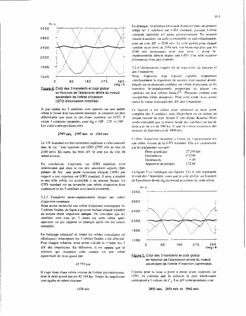
10-5
3200 E n pratique. on pourrait ctivisa~er d irio.cter dan.si in preinier3200 . > ~.temps lcs 3 satellites ýur (jl( standaid. puisquc I orbiile
2800 . 1 ~~optimale idcntifi/e est quasi Ceainar.l~seralenit2800 crisuite transferes sur ccile-ci enseinhkc ou individucilcmcrit.
/ ~pour un eo~it AV = 1530 in/,, Le .o/it global pour chaique2400. ateitie scrait done dc 2054 ni/s. soun tsaucoup plus quc Its
2160 rn/.s iiecessaires pour uric inis a. posk hi-
2000. 7 , im puisionneliledireecicdcpuis unc (.i 1. I'i iieicl solution
1600 - . .5 2 4 Oplanisalion coupie (t lal in rayc'~iv~re dIu Linceur el
-... .... des 3 frrnsferrs
1 200 Nous disposons d'un logiciel capahle d'optimiser
0. 90 . 180 270. 360 imultati~mcnt la trajectoire de montEe d un ianecur donoc.deg re plaqant un ou plusicurs smelhitcs sur orbite d injection. et Ics
Elg~Ure 42 CoOt des 3 transfefts et co~t global transferts hi-iiTpulsInionels permettant de placer ccsen fonction de I'ascension drofte du noeud satellites sur leur orhites ftnaksI5 Plulsturs cotecrcs soflI
ascendant de l'orbite d'ifjection %usceptibles d /ýtre minjinises flour ccltc etude. nous avons(GTO d'inclinaison moditti~e) choisi la valcur maximalc des AV des 3 Iransfe~rt%
Si par contre les 3 satellites sont mInjc sur une m~rme ('e loicll a ete iitilisc pour aepluimler la misc posteorbite ii tissue d~un lancement multiple. la situation est plus complete des 3 satellites. dins lliypothese ou on utilise undi/favorable que dans lec as d'une injection sur GTO. 11 unique lanceur du type Ariane 5. tire depuis Kourou. Nousexiste 3 solutions optimales. pour 14) = 108". 228' et 348. avons consird/r que la masse tinale des satellites en tin dcL~es co/its correspondants sont: inisc a poste est de -5001 kit. et que la vilesse U ciecenon des
moicurs de transtert esi de 3000 rn/s.2797 m/s, 2797mn~s et 1315m/ns
I ;mi ic d'inrje tion idcnt it ia F issue dc I optiai s atio n Cst
Le t.V maximal est tres nettement superieur a celui cotmstat/ une orhite voismne de Ia GTO standard, Idlle est tearact/riscedani leceas 'une injection sur OTO (2797 rn/s au lieu de par les parametres suivailts,2160 mis). En outre. les tLrois AV tie sont pas du tout du Demi grand axe: 27 266 kmnmime niveau. lixcentrciete: 0.7291)
Inclinaison: 6 45'En conclusion. ['injection sur GTO niodifike necst Argument du perigee. 172.94'interessante que dans le eas des lancement s/pares. Idlepermet de fair une petite 6conomie d'ergols (16%) par L~a figure 5 cst l'analogue des figure% I ct 4. Oel represcrnterapport a une injection sur GTO standard. If rcste a 6tudier le co/it des 3 transferts, ainsi que lec out global. en fonictionsi une telle orhite est accessible a un lanceur Ariane. La de ['ascension droite i1o du nocud ascenidant de cette orhite.OTO standard est en revanche une orbite d'injection hicnsup/necure sitles 3 satellites sont lane/is ensemble. m/ S
3200.
5.2.3 Transferrs ninow-imapulsionneLT depuis unt' orbits'd'injection commune 2800.
Nous avons recherchai une orbite d'injection ititerceptanit les3 orbites finales. de faqon a pouvoir r/aliser chaque tratisfert 2400.- '
au moyen d'une impulsion unique- On considere qlue Ics *..'
satellites sont tous les 3 situ/s sur cctte orhite apres\.injection. cc qui suppose en pratiquc qu'ils ont /i/ lance/s 200-ensemble. * *\
1600. +-
[In balayagc exhaustif de toutes les orbites (circulaires onelliptiqucs) intereeptant les 3 orhites finales a 06/ effectu6- 1 200 .-
Pour ehaque solution. nous avons caltulii Ia s'-nme des 3 0. 9 8 7 6AV des impulsions. En d/finitive, il est appars que Ia. deg T esolution qui minimise cette somme est tine orhite/quatoriale de demni grand axe: Figure 5* Co~t des 3 transferts et co/il global
en fonictton de Iascension drorte du noeud
42 755 kmn ascendant de I'orbite d'in jection (optimnis~e)
11 s'agit done d'une orbite voisine de l'orbite it/ostationnairc. ('omme pour Ia misc a poste a partir du ne injection surclont le demi grand axe est 42 1M4 km.'Toutes Ics impulsions (iTO, on constatc que la solution Ia plums intcressantesont 6gales et valent chacunc: correspond a 3 valeurs dc tl) Les AV correspondlants, sont:
1124 m/.s 2031 rni/s, 2031 m/ts et 1942 rn/s

10-6
Pour Itc alcul die la presion de radiation. les
Cest dlans cc cas que la valeur maximale des 3 AV est Ia caracteristiques physiques retenues pour les satellites sont
plus petite. Cest clans cc cas igalcment qu'ils sont les plus k~s suivantes.voisins Ies uns des autres. Ces risultats corresponident a desmasses d'ergols consommies valant respectivement: surface cxpos~e: 3 m2
massc: 500 kg
97%. 97% et 91% de la masse finale d'un satellite. coefficient thenno-optique global 1.2Par rapport it une mist a poste utilisant une ('ITo standard,on observe une reduction d'environ 8% die ia mnasse d'ergois 6.1. LI tigranon du mouri bnen! des soii'llites
maximale. L'analyse die [usury des orbites sous Finfluenice desperturbations naturelles a it r~alisee en utilisant un premierlogicicl d~veloppý ii lONEiRA 4ui pcrmect unc integration
6. MAINTIEN A POSTE rapide et fiable do mouvetnent orbital. Cc logiciel utilise ItL'analyse die performance qui a permis die proposer la formalisme des parainctres centres toil parametres moycos)constellation itudide a it ri~alisic sans prendre eni coinpte qui permet de supprimer les perturbations a haute fr~quencc,
Ies principales perturbations naturellcs agissant Sur Ies qui n'ont que peu d'influence Sur 1'ývolution a long terme diesatellites de la constellation, La prise en coinpte de cciles-ci ['orbite. Ucla autorisc ainsi lutilisation de grands pas
est en effet inutile pour analyser la performance du systerne Jznt~gration (typiqoement de lordre dec la ptinode orbitale.
sur one durie de 24 heures. Cependant. i1 est clair que It SOIt 24 heurcs ici). au lieu die quelques minutes si I'on uttltse
service fourni par It syst~ne envisage na dlift~rt que si les elemncits oscolateors dic l'orhite tsIkments instantanes)
celui-ci est disponible pendant une durie nominale ('ettc technique permet doiic de reiliser rapidemcnt dess etendant sur plusieurs ainndes. Hl convienit die vdrifier que Ia integrations die longue dur~e.constellation proposde est viable vis a vis die cc critcere, etquecn particulier les perturbations subies par Ics satellites Pour analyser I Evolution de la pertornwme~ do svstrn~c souscomposant la constellation nfimposent pas des mnanoeuvres ['influectic des perturbationts naturelic,. les parametresdie maintien a posit trop friqoentes ou trop cotctuses. iorhitauIx des, trois satellites conzide& ~ton integres avec Ic
logiciel prdcddemment di~crit Perioditlemicrit on rcleve Ia
L'6tode dlu maintien a poste a done iýtý rtialis~e en deux valcur deC ces parametres et on ICS AIItitC pour di.ltrrnincr la
temps: tout d'abord. Ics principales perturbations agissatit nouvelle couvertore do sysicie apres lieriurbation d'orbite.
sur lts satellites ont dtit simok~es. et lintlucrnce des Ein pratiquc. Ics caleuls die couverture o ii ie rIaISdS tow.
digradations d'orbite sur la performance do systeire a etcr les 7 jours; et Ia dortie globule darialyse conisecutive cst die 66valode. Dans on deuxiirme temps, pour tin cycle JI: mois. La (late de ddpart dec lanalyse a etic fixec au I lanvicr
correction d'orbite choisi au vu die [analyse pr&&c~lntQ. ties 1993. (ette date a one influence directe sur le resultatmanoeuivres die maintien a poste ont dt6 di~terininties et Ie puisqu'elle fixe la position relative tIc la Terre ci des autrescoca global die maintieni a poste a titi evaluti. istresý pertorbateurs. l!ie analyse plus poossec devra done
Zýtre realistie. poor 6valuer notaniment [Iinfluence de Ia dateLe satellite giostationnaire n'a pas tittir pris en comipte poor Lie lanecinent.cette analyse pour Its i-aisons suivantes: coinme il a 6indiqui en introduction. la charge utile tIe navigation 6.1.2 Calcul de la cou uerturepropreinent dite sera d'un volume et d'une mnasse liinitde. cc Afin die pouvoir eomparer correcteincent la couverturc die laqui autorise son adjonction sur on satellite gtrostatiotinaire constellation "perturb~e- avec la couvcrture nominale. il addvolu a one autre aetivit6 principale (06ldommunicatioo cte procudtid tIc Ia mnaniecr soivatite:par exemple). Dans ces conditions, le inaintien a poste d~e ccsatellite sera fix6 par les exigences tde position nement fin do - Le contour die Ia zone die coovertore nominale asatellite dle ldldeommunication. Par ailleurs. si [~on envisage 6t6 modelisii approx tin ativenincn par on polygoned'utiliser on satellite gdostationnaire puremeot dirdiid l a sphdrique. que l'on peoit Observer sur Ia figure I.mission die navigation, I encomnbrement die I orbitegiostationnaire imposera ii celui-ci one fen~tre de - tn ruiseau de points sitocs a la surf ace dec lastationnement limitie. Le respect die cette fenetre Terre a 6t6 defni a lintericur tIe cc polygone. (Cesndcessitera on maintien it poste d'un niveao comparable ii points soni rtipartis Siir des paralleles tdisposd-s touscelui d'un satellite girostationnaire die tirldeommunication. Ies 2' en latitude. Sur ehaque paralkle. les pointssnit environ 50 rn/s/an en terme de vitesse caractdristique. sont eqoi-repartis en longitude ct [eur nombre est
choisi de telle faqon qoc la densite surtaciqoc die6.1 Usure naturelle des orbites points soit approximativement constante SurCompte tenu de la nature des orbites, les pert urbations lecnsemble do reseau.principales qu'il convient die prendre en compte soot Icssuivantes: - Lanalyse de couvertur- est riralisde en intigrant
Ia constellation sor 24 heures Ipiriode die-dissymdtries do potetitiel gravitationnel terrestre, recouvretnent die Ia constellation nomitale) et en-attraction gravitationnelle de Ia Lone et do Soleid. testant toutes Its 5 minutes Ia valcur do PDO)P enpression de radiation solaire tdiecte. chaqoc point do rtrseau- On de6termine ainsi It
pooreentage des points oi leI service tIc navigationIxe potentiel terrestre a 6t6 modilis6 en prenant en compte est accessible en permanence sur Ia durireIts termes zonaux et tessdraux jusqu'i l'ordre et Ic degrir 8, d'intigration. L~e service est dii accessible a on
instant donni si il y 3aus moins 4 Satellites visibles

itcet instant. et si he IP[X)P est inf~icur a 6. Plus aucune regioni ne blrifoicic d'un scrs ike permanent etCompte tenu de la rtepartition des poiints du reseau. la zone ha plus privilkgice ýiihit des pcriodesce pourcentagc est aussi le pourcentage de la d'indisponihilit6 journahiere pouvant aticindre 4 heures [-.i
surface couverie. 11 est exactement de 99,6% piour ioutre. les re~gions Furopecinc,; sintitirc-, vile privecs de[a constellation nominale. La performance dic ha service.11 cst donc chair qu'un mainticil a pouatc relativernent
constellation d~grad~c a toujours 61 chiffr-ice au friquent estr ntccssaire,moyen de cet indice.
6.2 Strategic et co~it de maintien it poste6.1.3 Risu~iras de i'ancat vseLa figure 6 rcpr~sentc levohution du pouicentage tic Ia 6 2. 1 Fr.ýqience (it nui intien a poste
surface du polygone couverte par la constellation en L~e premier parametrc a choisir plour 6'alucr he coiit dcfoniction du temps (exprimti en semainesi. inaintien a poste eat ha trequencc des corrections. Phusýicurs
% ( sur f ace) tactcurs pcuvenit influce sur sont choix.
le niveau de dcti.radahton toherabie pour ha zone dccouvusrture.
h5 a durce d'indisrombiihiti Liu service: les
manoeuvres rendent tres certainerent he systemetemporairement inutilisahhe d a precision de
50 localisatioin des satehlites est alors trop faihle pourpermeitrre une navigiation de quahiiuf.
IC L061 global dU Maintien a postc. la frequenee
25. d es iiianocuvrcs pcut dma ne 1C cri'ainc rnesureintluer stir cc coit6 e ciias tic non himearite du niveau
dhes pertiirhations en olicuio Liu wicips.0.
0 6 .12 flour cctic premiere anahyse. imu~s astins duccide~ de proctiders m a un recalare des orbites ties sjiechhics iouitcs lcs 9 semaines.
Figure 6: Evolution naturelle du pourcentage de L~a figure 8 permet de juger de ha deg~radation de ha
couverture en fonction du temps performance ohtenue apres un ete delai sans recahage. Onpeut constaler que he service ,.eat essenit~ehllcnent digradti auSod. et que IhEurope reste ciirrecteinent ciuverte. ILe choix
('etic figure montre que ha catoverture dantino crhetcnicnt el cAs 8 ,cmnaincs semible constitucr un hon compromis: uneprogressivement pendant 6 semaines. puis cette diminution duri~e plu~s longue conduit a tne pcrte de couverture timp
s'acciekre pour ahoutir a une disparition complete dle la timportance sur Fl~uriipe. ailrs quuric tr6quencc decouverture apres 4 mois eniviron. manoeuvre plus c..hv~c diininucrait fortement la
hisponihihitti dui service.ILa figure 7 reprsesinte Ia couverturi. die ha cionstelhation a icc[
instant.
X..
360
X,'
Figure. 8@ouverture do la constellationFEigure 7 Couverture de la constellation apres 4 mois apres 8 semaines
Indisponibihite journaliere (inn) I ndisponibihite hournahiere (mit)

10-8
I'aplatissement tie Ia rTetr qui attenit eniviron 0,8' apres, 8L'analyse du codi de maintien 1 po~sle doit ýIrc rcahisee en scinaincs. necst bien cntendu pas corrig~e puisqluil 4uffit dedeux temps: tout d'ahord. ii convient tie determiner quels modifier l~gercmcnt It denta grand axe initial lef, orbitessont les pararn~crs qu'il est absolument n~cessaire die pour que la lo~ngitude des nocuds ascendant,; par rapport a ]a
goner: ii est en effet possible quc la sensibiliti~ die certains trerselx.Dsmneve ec yeefcueparametres sur le service soit suffisaminent taihlc pour qlue toutes lea 8 setnaines permettent d'as-urer une couvertureIon puisse se permettre die ne pas les corriger %ur toute la qui reste toujours supEricure a 9014 de ia Louverture inittaledurce do service. lEnsuite. It co~t des corrections a r~aliser pendant lts 7 annees tic durce dic vte envisagces pour Itdoit W~e calculi. Pour cela. It If g iciel tioptitnisation tie Nystemc.mianoeuvres bi-impulsionnelles. deja utilis6 pour lorde dela niise ý poste. a de nouveau ýt mis en oeuvre. 6.2.3 LCotil du mauinoien 6 poste
Comme on vient de Ic voir. It maintien a poste envisage6.2.2 Maznoeuvres de inainhien d posre riticessite tic cormger Ia toalitt des paramescres orbitaux.tine etude exhaustive des poasibilit~ de mnaintien a posit tie N~iantooitis. la correction ties nocuds ascendants ayantIa constellation a rtit r~alis~e. en testant successivement Ia uniquement pour hut tie matintnir Ia disposition relativeni~cessild de corriper chacun des parametres orhitaux. inotiale des plans d'orhite. il suffit tie inanoeuivrcr deuxCompte tenu de la volonti de r~aliser des satellites simples satellites sur les trois pour rt~aliser ceite operation. L'identit6ct peu coriteux, les prcini~rcs analyses ont to pour but tie ties satellites a manoeuvrer peut atre choiste dc diff~rcroesverifier s il 6tait possible tie se contetiter tie Inanocuavres- l.qots. pour cette premiere ainalyst, 2 scenartos die maitotteneffectuces scion ]a vitesse du satellite. ou 1 Ia rigueur dans a poste ont 6t6 envisagcs:Ie plan dc lorbite. Le hut 6tait d'6viter si possible desmanoctjvres de modification du plan die l'orhiie. qui sont a) oin permute r~gulicrcincnt le satellite quitinecoiteuses et qut imposeto une plate-fotme plus comiplexe ilattoeuvre pas.pour le satellite. h)on manoeuvre lea satellites qut perinetteni de
mionitniser la somnine totale tie variation tingulatre aCes tests ont malheureusemerit monlrc que cela necst pas r~aliser.possible. La figure 9 represente 1l6volution tie ]a couveriuredi. systeme dlans l'hvpothisc die correctiot,; dans le plan tic Pour tcster chacurit tic .es oplions. l'enuisetil ties logictelsl'orhitc seulement (correction du tiemi grand axe. die tinentionnes jusqu Ia present a cim6 uttlts&Ilcxcentruicitý. tie ['argument do pcrig~c ci tie l~anonialievraic de l'orhite). (On constate une perle progressive LiC la - integration en 0lm6nents centr~s ties orhites die lacouverture nominale: celle-ci tiest pas totaleoteoit rt~cuptinrte Constellation.a ['issue tie chaque mianoeuvre et la situatiotn tie tail - caicul tie la pert ormnance avant et aprcs les(lu'etpirer avec It temps. toianocuvres tie correction.
.calcul do C061t minimoal dies manooeuvres tic%(surface) correctotn.i, nodfulisties par ties transferts hi-
1 00 - .tonpulsionnels.
94 -Dana le calcul effectuti. It co~it ties inant-wuvrca de phasage
contiu qu il eat possible d'obtenir It phasage disiri en89 H it~alisant one 16gcre modificationt du tiemi grand axe de
I~ lorhite. pla~ant ainsi Ie satellite sur une orbite de dirive.83. - K lne secontie inanoeuvre. faite en sens inverse die Ia
premiere. permet die re-stabiliser Ic satellite une fois It78. *~ tiphasage souhait6 ohtenu. Le co~t sIc cette manoeuvre
d~petid hien entendu dce Ia durde toldr~e pour l'obtention du________________________________ phasage. Les premie~res 6valuatiotis r~alis~cs ont montri
72. ~ I P qu'un dclai tic 24 heures permel die rentire Ie coOt du0. 21 . 42 . 62 83 . 104 . phasage nm~gligcable visa via du co~l ties autres
s emai n e manoeuvres. c'est pourquoi cc coal n'a pas 06i pris encol"pte par Ia suite.
Eigure 9 Evolution du pourcentage de couvertureen fonction du temps. Aprcs avoir lestil Its deux scenarios tie inatnhten a posteCorrections dans le plan de l'orbite. m6voquda precildenrunent, il s'avcre logiquement que le
11 a avere done n~ccssaire (IC rtialiser migalcinent ties second cat It plus ilconomique. D~e plus. cest celui qutcorrections 'hi plan tie lorhite (inclinaison et ascension assure Ia mneilleure rc~partition ties masses decrgolsdroite dhi nocud ascendant). IEn cc qui cor.cerne cc dernier cotisormmees par les trois satellites.param~tre, lea manoeuvres realisces se contentent tiassurerqlue lea 3 plans d'orbite conservent Ia disposition relative Le coat total tiu mainlien i poste a 616~ ilvaluil en rilalisantquils avaient initialement. En effet, sous I'influence des Line simulation complete aur 7 ans. Leas risultats obtenustermes tessilraux du potenliel gravitationnel terreatre ct sous figurent dans It tableau tie Ia figure 10.celle de ['attraction luni-solairc. Ia vitesse de rotation tiesplans d'orhite differe suivant lts satellites. En revanche. Ia On constate. que Ic coi~t teic nainlien a poste s'avirerotation d'ensemble des plans d'orhite, due cisentielleinent a relativement plus dlevil que celut d'un salit

101-9
geostattonnatre (85 rn/s/an contre 50 pour un economic moxleste t8%, en massei.#ostationnaire). Cc cout reste neaninoins tok~rable, 11conviendra de verifier s'il necst pas possible. par un choix lDans le cas ouj les satellites mont iripectes sur GMTadliquat de la position des nocuds ascenrdants initiaux. de individluelleinent. Ic coiit du transtert est tres voisin de celuilimiter le niveau des perturbations diffircrntielles affectant Sun satellite geostiontraire. (ine teldc procedure de misc ales plans d'orbite et de r~duire ainsi le co~it glohal dc poste est cependant d~licate car elle impose I heure dc tirmaintien it paste. des deux dernilers satellites lances.
Satellite 1 2 3 Ldttudc du inaintien ai poste a neccessiic dans un premierI ~temps d'analyser Vivolution de la couverture du service dc
Co~t nnue 85 5 78navigation sous linfluence des perturbations naturelles.Coat nnue 85 5 78Cate analyse a permis de montrer qu'un maintien a paste
(Jmis) relativement frequent srimpose (toUteS le 8 semnaineSCoa~t total 592 592 546 environ) pour assurer 1, permanence d'une couverture
(m/s) convenable.Masse totale d'ergols 22 22 20
(% mase fiale)Le coat des manoeuvres de maintiien a paste necessau-e aensuire ýt ivalui sur Ia base d'une duree de vie des
Figure 10: Coat du maintien aposte sur 7 ans satellites de 7 ans. Cette premierc analyse semhle indiquerque le co~it annuel des manneuvres s'61eve a environ 85 mis
7. CONCLUSION (contre 50 m/s pour un satellite gcostationnairej.Le but de l'itude prisenitic dans ect article ctiat dc realiserune analyse de la faisabilitti d'un systemne dc navigation Pour parachever [analyse dc mis,ýion d un tcl systeme. ilfonictionnant suivant le principe du systeme UPS et assurant conviendra disormais de virifier s'il est possibh. .t; localiserune couverture permanente de ['Europce t de l'Affique a' de tels satellites avec une precision suffisanic pour foumnir['aide de 4 satellites seulement dont un geostationnaire. une precision de navigation acceptable.
Les pamiuantres orbitaux initiaux de cette constellation sont X. REFERENCES B[BLIOGiRAPHIQUESissus d'une itude antirieure1 21 consacr~cii l a recherche dcconstellations it faible nombre de satellites. La constellation III D. Kromer, J. Landis, J. Dobynepr~sentee ici pr~sente plusicurs caracteristiques "Navstar Global Positioning System (UPS)intdrcssantcs: System characteristics -Preliminary Draft-
STAN AG 4294. Draft Issue L. 1 August 1990.- tris faible nombre de satellites (4 satellites est leminimum requis pour assurer un service de 121 H. Baranger. H. Piet-Lahanier, J. Bouchardnavigation du type UPS). "Global Optimization of UPS Type Satellite- tous lea satellites sont visibles en permanence de Constellation"la meme station de contr6le: il eat amnsi possihie Papier IAF-91-369.utiliser lea satellites comme de simples repeteursd'un message de navigation ilabord au sol. 131 (;.A. Bekey, S.F. Nlasri- orbites relativement "classiques". "Random search techniques for optimization of
non-linear systems with many parameters"L'm6tude de faisabilitd pr~sent~e ici s'est surtout attach~c a Math. Comput. Sitnul.. 1983. 25. pp. 210-213.analyser lea problkmes poses par la mise et le maintien ýipaste d'une telle constellation. 141 L. Pronzato, E. Walter, A. V'enot,
J.F. LebruehecLitude de la mise a poste a 6tte faite en consid~rant diverses "A general-purpose global optimizersolutions: implementations and applications'
- lancement individuel de cliaque satellite. ou Ian-Mah optSiu.14.2.p.1222
cement couple des 3 satellites non g~ostationnaires. 151 L1. Zaoui, B. Cristophe- injection prfliminaire sur une orbife GTO standard "Optimisation de lancements multiples(Geostattonary Trransfer Orbit) d~fivrt~e par un Ian- Agard Symposium (Tacsats f-or surveillance.ceur Ariane. ou injection sur une orbite &di~die a la verification and C311misc a poste de ces satellites de navigation. Bruxelles. 19-22 Octobre 1992.
11 eat apparu que l'orbite GTO standard Ariane cotistitue untr~s bon choix pour l'orbite d'injection. surtout si les 3satellites non ginstatinnnaires sont mis it poste a l'aide d'unlanceur unique. Dana cc cas. le co~t de chaque transfer( necd~passe pas 2160 m/s en vitesse caract~ristique. 11 eatcependant heaucoup plus flcvi que celui d'un satellitegdostationnaire (1500 m/s). L'orbite d'injection qui permetde minimiser )a consommatinn d'ergols des transferts demisc a poste finale diffcre peu de Ia GTOý elle conduit ii une

10-10
Discussion
Question: Please provide the definition of TACSATas intended in the paper presentation.
Reply: TACSAT is understood to be a theater satellite,that is to say, a system available where you wantand when you want. This leads to consequences notonly on the space platform but also on the groundsupport equipment.

Tactical Satellites for Air Command and Control
M. Crochet - J. Cymbalista - L. LevequeAEROSPATIALEEspace & Defense
BP 2 78133 Les Mureaux Cedex France
This paper is divided in three parts corresponding to the c. Adverse satellitesfollowing items: A theater commander has to know the locauon and
coverage of the adverse observation satellites.- air command and control functions and defficiencies, Today this function is performed by the Air Force and- contribution of TACSATS to air command and the satellites tracks are not included in the RAP, because
control, this information is considered as a basis for threat- operational improvements due to TACSATS. evaluation or intelligence.
There is a requirement for the European countries to beable to fulfill this function with independent means.
1. AIR COMMAND AND CONTROLFUNCTIONS AND DEFFICIENCIES
1.2 Resources managementAir command and control functions are divided in fourthemes: Resources management is divided in three themes:
- surveillance, - force management,- resources management, - airspace management,-air activity control, - C2 resources management.- intelligence.
a. Force management1.1 Surveillance Force management includes the knowledge of our ownSurveillance includes the generation and dissemination forces state, the planning and tasking of air operations.of the Recognized Air Picture (RAP). Three key issues The key issues about this function are the interfacesare linked to this function, the detection of low obser- with a multitude of other systems, the Air Task Ordervables and low flying objects, the ballistic missiles (ATO) preparation and dissemination and the weatherproblem and the adverse satellites tracking. forecasting.
a. Detection of low observable. low flying obiect In order to plan the air operations, a theater commanderThe current solution to detect low flyers is to use the has to gather a multitude of informations coming fromcontribution of radars on aircraft (AWACS). This type different systems like:of platform may maintain its position during abouteight hours, and you need four to five of them to - the ennemy Order Of Battle (ODB) generated bymaintain a round the clock surveillance capability, intelligence system,The detection of low observables objects is solved bydeveloping a sensing net, using different frequency range - his own forces state generated by Army, Navy and Aircapability (visual, acoustic, infrared or electromagnetic) Force systems...and different angle of presentation versus the possibletarget. This leads to a costly multiplication of sensors This leads to a requirement of connection with athat must be in position on every possible penetration multitude of other systems and the correct interpretationcorridor, of the data collected by these systems.
b. Ballistic missiles Once this process has been performed, the TheaterThis new threat has to be included in the RAP. In order commander has to elaborate and disseminate the ATO toto do so, we have to detect the missiles in flight as soon all the relevant units. These units are scattered on theas possible and track them during their flight. Theater and may be connected by National means orA ground system like the PATRIOT has a limited Allied systems.detection capability coherent with the interceptorguidance. The planning function supposes for all the militaryA current satellite like DSP (Defence Support Program) operations that you are able to forecast the ennemywas designed to detect a long range ballistic missile operations, your own operations and the weather. Forcoming from a well known area. It has limited capa- this purpose you need adequate informations on thebility against a short range ballistic missile coming weather on the Theater and also outside the Theater.from a country involved with missile proliferation.

11-2
b. Arspace management 1.4 IntelligenceAll the air operations use a common mean that must be Intelligence function is in charge of ennemy ODBshared, it is the airspace. In order to do so you must be assessment and forecasting and damage assessment. Thisable to collect all the requirements in airspace coming supposes the gathering of all types of information:from the different units (Air Space Request) and disse- visual, electromagnetic ..., the fusion of these differentinmate the Airspace Coordination Order (ACO) to all informations and the dissemination of the relevantthe relevant umits. information to operating centers or units spread all
along the Theater.This airspace planning is coordinated with the ATOplanning and distributed three to four times a day to theunits, this represent a hudge amount of messages spread 2. CONTRIBUTION OF TACSATS TO AIRall over the Theater. COMMAND AND CONTROL
c. C2 resources manapement 2.1 SurveillanceThe air operations are performed using operators, For surveillance function, TACSATS may provideground-air-ground coimunication nets, consoles... queuing to the current sensor net by different means.All these C2 resources must be allocated according to First ELINT or COMINT satellites may provide infor-the current ATO corresponding to the Air Directives. mations on ennemy airbases activity and trigger theThis supposes a hudge information exchange between AWACS take-off.the different C2 entities. The process of these informa- If these informations are not available, radars or electro-tions, and the planning of the best C2 resources optics satellites may provide ennemy raids early detec-allocation according to the Air Directives. tion in order to alert the Theater sensor net and activate
the relevant sensors.
1.3 Air activity control For the special case of ballistic missiles, launchersdetection may be provided through radars or electro-
Air activity control is divided in two functions: optics satellites. Missile launch preparation may bedetected through the use of ELINT or COMINT
"- air traffic control, satellites picking-up the corresponding electromagneticsignals. In last ressort, missile launch detection may be
- air mission control. detected by infrared satellites picking-up the plumes ofthe incoming missiles.
a. Air traffic controlAir traffic control supposes first a flight regulation, that 2.2 Resources managementis to say an allocation of the corresponding airspace and For resource management, meteorological satellites mayC2 resources to the traffic requests. This supposes the provide the relevant information in order to process thecollection of all the flight requests, the process of 24 to 48 hours forecasting necessary for the planning ofallocation in coordination with the airspace management air operations.function and the dissemination of the flight autorisa- Broadcasting TACSATS are a good mean to disseminatetions to the relevant units, the ATO message (force management) and the ACO
(airspace managememit) to all the units widespread on theIn aiditif,-, -. i trol is in charge zi Ccarcb And Theater.Rescue (SAR) operations, mainly based on the accuratelocation of the friendly crews. Ground-to-ground TACSATS are a good mean to solve
the operational requirements of:b. Air mission controlOnce an air operation has been planned according to the - other systems database interrogation (force manage-ATO, this operation has to be controlled by air mission ment),controllers, this supposes a good coordination betweenforce management and air mission control function, that - Airspace Control Means requirements diffusion (air-is to say a hudge amount of information exchange. space management),
There is also an issue linked with radioelectric propaga- C2 assets availability (C2 resources management).tion phenomena, it is control of low flying aircrafts.This supposes a hudge amount of antennae wide spread The technical involved consideration are the quantity ofalong the theater to offer the communication means to information exchange and the widespread on the Theaterair mission controllers. of the different units involved in these functions.
Once a mission has been performed, the mission report 2.3 Air activity controlmust be prepared at the unit level and disseminated to Navigation TACSATS (signal location type) is thethe relevant operation centers for intelligence gathering most efficient solution for aircraft localization, which isand force managemient planning function, the major defficiency of search and rescue operations.
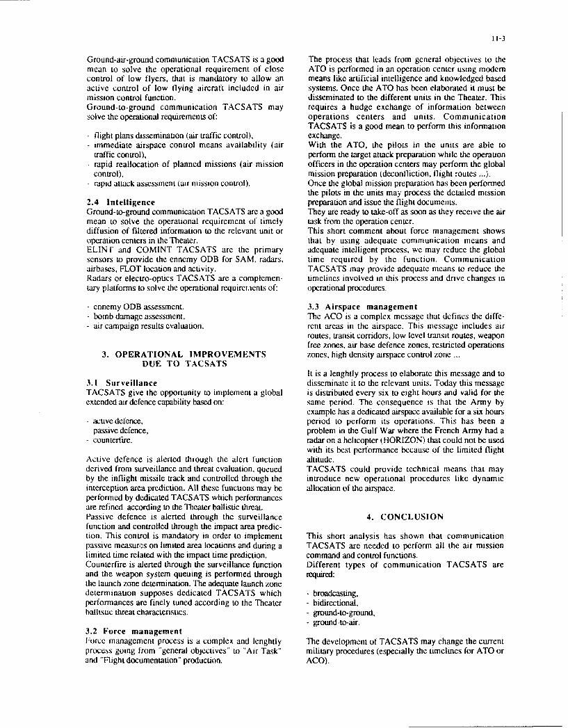
11-3
Ground-air-ground communication TACSATS is a good The process that leads from general objectives to themean to solve the operational requirement of close ATO is performed in an operation center using moderncontrol of low flyers, that is mandatory to allow an means like artificial intelligence and knowledged basedactive control of low flying aircraft included in air systems. Once the ATO has been elaborated it must bemission control function. disseminated to the different units in the Theater. ThisGround-to-ground communication TACSATS may requires a hudge exchange of information betweensolve the operational requirements of: operations centers and units. Communication
TACSATS is a good mean to perform this information- flight plans dissemination (air traffic control), exchange.- immediate airspace control means availability (air With the ATO, the pilots in the units are able to
traffic control), perform the target attack preparation while the operauon- rapid reallocation of planned missions (air mission officers in the operation centers may perform the global
control), mission preparation (deconfliction, flight routes ... ).rapid attack assessment (air mission control). Once the global mission preparation has been performed
the pilots in the units may process the detailed mission2.4 Intelligence preparation and issue the flight documents.Ground-to-ground communication TACSATS are a good They are ready to take-off as soon as they receive the airmean to solve the operational requirement of timely task from the operation center.diffusion of filtered information to the relevant unit or This short comment about force management showsoperation centers in the'lheater. that by using adequate communication means andELIN f and COMINT TACSATS are the primary adequate intelligent process, we may reduce the globalsensors to provide the ennemy ODB for SAM. radars, time required by the function. Communicationairbases, FLOT location and activity. TACSATS may provide adequate means to reduce theRadars or electro-optics TACSATS are a complemen- timelines involved in this process and drive changes intary platforms to solve the operational requirei.ients of: operational procedures.
- cnnemy ODB assessment, 3.3 Airspace managementbomb damage assessment, The ACO is a complex message that defines the diffe-
- air campaign results evaluation. rent areas in the airspace. This message includes airroutes, transit corridors, low level transit routes, weaponfree zones, air base defence zones, restricted operations
3. OPERATIONAL IMPROVEMENTS zones, high density airspace control zone ...DUE TO TACSATS
It is a lenghtly process to elaborate this message and to3.1 Surveillance disseminate it to the relevant units. Today this messageTACSATS give the opportunity to implement a global is distributed every six to eight hours and valid for theextended air defence capability based on: same period. The consequence is that the Army by
example has a dedicated airspace available for a six hours- active defence, period to perform its operations. This has been a- passive defence, problem in the Gulf War where the French Army had a- countertire. radar on a helicopter (HORIZON) that could not be used
with its best performance because of the limited flightActive defence is alerted through the alert function altitude.derived from surveillance and threat evaluation, queued TACSATS could provide technical means that mayby the inflight missile track and controlled through the introduce new operational procedures like dynamicinterception area prediction. All these functions may be allocation of the airspace,performed by dedicated TACSATS which performancesare refined according to the Theater ballistic threat.Passive defence is alerted through the surveillance 4. CONCLUSIONfunction and controlled through the impact area predic-tion. This control is mandatory in order to implement This short analysis has shown that communicationpassive measures on limited area locations and during a TACSATS are needed to perform all the air missionlimited time related with the impact time prediction. command and control functions.Counterfire is alerted through the surveillance function Different types of communication TACSATS areand the weapon system queuing is performed through required:the launch zone determination. The adequate launch zonedetermination supposes dedicated TACSATS which - broadcasting,performances are finely tuned according to the Theater - bidirectional,ballistic threat characteristics. - ground-to-ground,
- ground-to-air.3.2 Force managementForce management process is a complex and lenghtly The development of TACSATS may change the currentprocess going from "general objectives" to "Air Task" military procedures (especially the timelines for ATO orand "Flight documentation" production. ACO).

11-4
I TACTICAL SATELLITES FOR AIR COMMAND AND CONTROL
AIR COMMAND AND CONTROL SYSTEM FUNCTIONS (1)
AIR COMMAND AND CONTROL SYSTEM FUNCTIONS (2)
TACSATS FOR SURVEI LLANCE
TACSATS FOR RESSOURCES MANAGEMENT
TACSATS FOR AIR ACTIVITY CONTROL
TACSATS FOR INTELLIGENCE
OPERATIONAL IMPROVEMENTS FOR SURVEILLANCE
OPERATIONAL IMPROVEMENTS FOR FORCE MANAGEMENT
OPERATIONAL IMPROVEMENTS FOR AI RSPACE MANAG EM ENT
CONCLUSION
VU-GRAPHO
(AIR COMMAND AND CONTROL SYSTEM FUNCTIONS (1))
FUNCTIONS KEY ISSUES
LOWOBSERVABLES, LOW FLYING OBJECTSAIRSPACE SURVEILLANCE BALLISTIC MISSILES
ADVERSE SATELLITES
FORCE MANAGEMENT INTERFACE WITH THE OTHER SYSTEMS (INTELLIGENCE.ELECTRONIC WARFARE...)
AIRTASKORDER PREPARATION AND DISSEMINATION
WEATHER FORECASTING
AIRSPACE MANAGEMENT "REALTIME"ALLOCATION OF THE AIRSPACE
"AVAILABLE'AIRSPACE DISSEMINATION
C•2 RESSOURCES MANAGEMENT
E RAINFORMATION EXCHANGE WITH C2 ENTITIES
VU-GRAPH I

(AIR COMMAND AND CONTROL SYSTEM FUNCTIONS (2))
FUNCTIONS KEYISSUES
FUGHTS REGULATION
AIRTRAFFIC CONTROL COORDINATION WITH AIRSPACE MANAGEMENT
SEARCH AND RESCUE OPERATIONS
INTERFACEWITH FORCE MANAGEMENT
ACTIVE CONTROL OF LOW FLYING AIRCRAFTSAIR MISSION CONTROL
MISSION REPORT PREPARATION AND DISSEMINATION
i ENNEMYORDER OF BA1TLE ASSESSMENT
DAMAGE ASSESSMENTINTELWGENGE
DISSEMINATION OF THE RELEVANT INFORMATION
VU-GRAPH2
TACSATS FOR SURVEILLANCE )
DEFFICIENCIES OPERATIONAL REQUIREM ENTS TACSATS TYPE
AIRBASES ACTIVATION ELINTANDCOMINTLOW OBSERVABLES,LOW FLYING OBJECTS
RAIDS EARLY DETECTION RADARS OR ELECTRO-OPTICS
LAUNCHERS DETECTION RADARS OR ELECTRO-OPTICS
BALLISTIC MISSILES MISSILE LAUNCH PREPARATION ELINT AND COMINT
MISSILE LAUNCH DETECTION INFRARED DETECTION
COMMUNICATION SATELLITES
ADVERSE SATELLITESOBSERVATION SATELLITESCOVERAGE ' H
VU-GIRAPK3
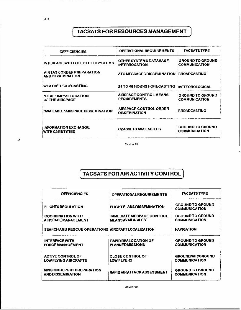
S1-6
f TACSATS FOR RESOURCES MANAGEMENT
DEFFICIENCIES OPERATIONAL REQUIREMENTS TACSATS TYPE
OTHERSYSTEMS DATABASE GROUND TO GROUNDINTERFACE WITH THE OTHER SYSTEMS INTERROGATION COMMUNICATIONAIRTASK ORDER PREPARATIONANDIRTASKORDER PREATO MESSAGES DISSEMINATION BROADCASTINGAND DISSEMINATION4
WEATHER FORECASTING 24T0 48 HOURS FORECASTING i METEOROLOGICAL
'REALTIME"ALLOCATION AIRSPACE CONTROL MEANS GROUND TO GROUNDOFTHE AIRSPACE REQUIREMENTS COMMUNICATION
1 • AIRSPACE CONTROL ORDER".AVAILABLE'AIRSPACE DISSEMINATION AISPEMCON O BROADCASTING
DISSEMINATION
INFORMATION EXCHANGE C2ASSETSAVAILABILITY GROUND TO GROUNDWITH C2 ENTITIES COMMUNICATION
VU-GRAPH4
(TACSATS FOR AIR ACTIVITY CONTROL)
DEFFICIENCIES OPERATIONAL REQUIREMENTS TACSATSTYPE
GROUNDTOGROUND
FLIGHTS REGULATION FLIGHT PLANS DISSEMINATION COMMUNICATION
COORDINATION WITH IMMEDIATE AIRSPACE CONTROL GROUNDTOGROUNDAIRSPACE MANAGEMENT j MEANS AVAILABILITY COMMUNICATION
SEARCH AND RESCUE OPERATIONSI AIRCRAFT LOCALIZATION NAVIGATION
INTERFACE WITH RAPID REALOCATION OF GROUNDTO GROUNDFORCE MANAGEMENT PLANNED MISSIONS COMMUNICATION
ACTIVE CONTROL OF CLOSE CONTROL OF GROUND/AIR/GROUNDLOW FLYING AIRCRAFTS LOW FLYERS COMMUNICATION
MISSION REPORT PREPARATION GROUNDTO GROUNDAND DISSEMINATION RAPID AIR ATTACK ASSESSMENT COMMUNICATION
VU.(vMAIH5

11-7
(TACSATS FOR INTELLIGENCE3
DEFFICIENCIES OPERATIONAL REQUIREMENTS TACSATSTYPE
ELINTANDCOMINTENNEMY ORDER OF BATTLE SAM. RADARS. AIRBASES. FLOTASSESSMENT LOCATION AND ACTIVITY
RADARS OR ELECTRO-OPTICS
BOMB DAMAGE ASSESSMENT
DAMAGEASSESSMENT AIR CAMPAIGN RESULTS RADARS OR ELECTRO-OPTICS
EVALUATION
DISSEMINATION OF THE TIMELY DIFFUSION OF GROUND TO GROUNDRELEVANTINFORMATION FILTERED INFORMATION COMMUNICATION
VU-GRAPH6
(OPERATIONAL IMPROVEMENTS FOR SURVEILLANCE)3
INTERCEPTION AREA IPREDICTION i"
iALERT
PREDICTION DETERMINATION,,
SREAL EXTENDEDAIR DEFENCE CAPABILITY
VU,-GRAPH7
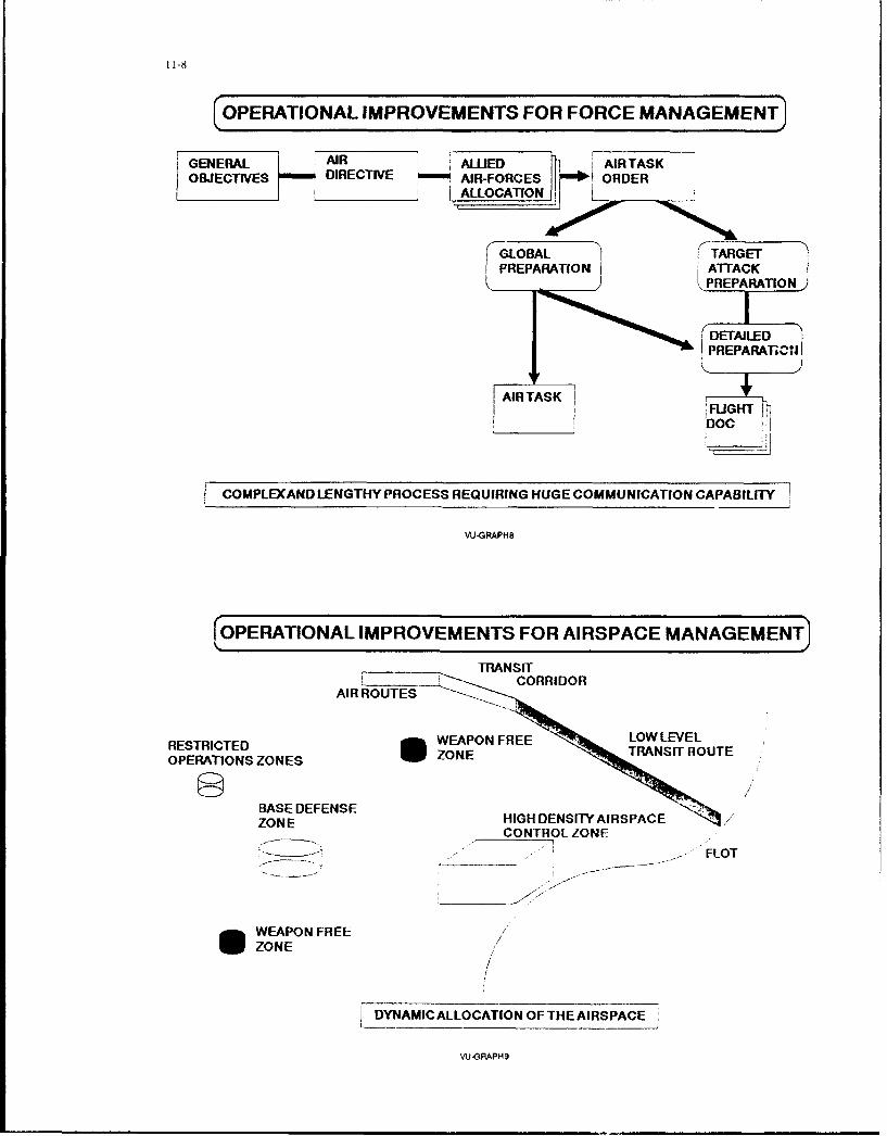
11i-8
(OPERATIONAL IMPROVEMENTS FOR FORCE MANAGEMENT)
GENERAL AIR ALLIED AIRTASKOBJECTIVES DIRECTIVE AIR-FORCES I ORDER
__________ iALLOCATION
GLOBAL TARGETPREPARATION ATTACK
S PREPARATION
DETAILEDPREPARAr"CjI
AIRTASK .
FLIGHT I________DOC
COMPLEXAND LENGTHY PROCESS REQUIRING HUGE COMMUNICATION CAPABILITY
VUGRAPH8
(OPERATIONAL IMPROVEMENTS FOR AIRSPACE MANAGEMENTJ
TRNICORRIDOR
AIR ROUTES " CORIDO
RETITDWEAPON FREELOLELOPERATIONS ZONES ZONE TAI UTE
BASE DEFENSE IGH T SPACZONE HIGH DENSITY AIRSPACE
CONTROL ZONE
FLOT"- ------__ ------ .. - F O
WEAPON FREEZONE
/
_DYNAMIC ALLOCATION OF THE AIRSPACE
VUGRAPH9
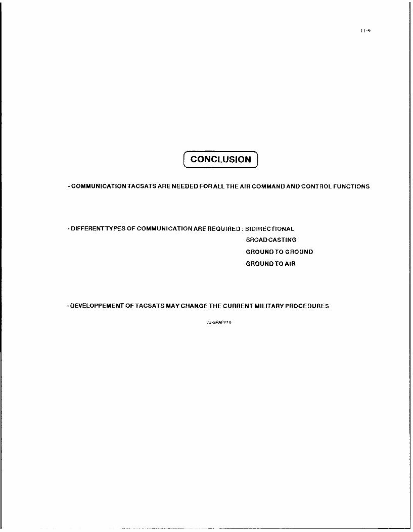
CONCUSION
- COMMUNICATION TACSATS ARE NEEDED FOR ALL THE AIR COMMAND AND CONTROL FUNCTIONS
-DIFFERENTTYPES OF COMMUNICATION ARE REQUIRED: BIDIRECTIONAL
BROADCASTING
GROUND TO GROUND
GROUND TO AIR
- DEVELOPPEMENT OF TACSATS MAY CHANGE THE CURRENT MILITARY PROCEDURES
AJ.GPAPH tO

14-1
CONSIDERATIONS FOR NATO SATELLITE COMMUNICATIONSIN THE POST-2000 ERA
by
A. Nejat InceMarmara Scientific and Industrial
Research CenterP.O. Box 21
41470 Gebze-KocaeliTurkey
i.The National Delegates Board of AGARD, upon vulnerability and does not provide communications for the
recommendation by ti;e Avionics Panel of AGARD. approved in polar region and submerged submarines The system
March 1988 the establishment of WG-13 to study satellite development in the past has been based on successive
communications for NATO under the direction of Prof Or- Nejat discrete steps in capability and spending and each
Ince of Turkey. procurement has contained an important cost element of R&DThere has been a minimum of joint national R&D and use of
2.Some 14 scientists/engineers, from research and industrial the NATO system which resulted, among other things, in
establishments of Canada, France, The Federal Republic of considerablL interoperability problems
Germany, Norway, Turkey, the United Kingdom, the UnitedStates of America as well as from International Military Staff of It was agreed that what was required for the coming decades
NATO and SHAPE Technical Centre, participated in the work of which may be characterized by 'uncertainty" and "shrinking
WG-13. military budgets' was a very flexible, modular SATCOM systemwhose communication capacity and resilience to ECM and
3.T h 1. spaper is a b r i.e f summarny physical threat can be modified when operational requirements
of the studies carried out by the group in the change. however, without having to undertake excessive R&D
period 1988-1990 on the type of satellite communication and total replacement of the space segment
systems which NATO can have in the post-2000 era includingthe critical techniques and technologies that need to be 6For the development of system architectures to achieve
developed for this purpose. flexible and highly cost-effective SATCOM options for NATO. atechnical survey has been made and information collected on
4.In accordance with the Terms of Reference, the Group the satellite system concepts being considered nationally
considered.a time period beyond NATO IV and other national (Canada, France. FRG, UK and USA) and internationally (ESA,
systems now in the implementation or planning stage, which Intelsat, Eutelsat. INMARSAT) for both civil and military
would cover a time span of 20-30 years, i.e. 2000-2030. It was applications as well as on related technological R&D activities
recognized that the earlier part of this period would be and operational aspects regarding threat and environmental
constrained by the existing and planned assels but the later factors such as propagation and the usage ol frequency
part would be, and should be, more technology-driven. The spectrum.
following assumptions are made which take into accountperceived trends and desirable attributes for future SATCOM 7.The status of the following techniques/technologies€ and
systems: concepts which appear feasible and exploitable by futureSATCOM systems and which are consequently being
i) The area of interest for NATO will remain as is to-day and investigated nationally and internationally have been described
will include the polar region in the report.
i) multi-beam/phased-array antennas with adaptive spatialii) The use of SATCOM will be more pervasive particularly nulling and multiple transmit spot beams.
for small mobile users (aircraft, land-mobile, Ships andsubmerged submarines) to support general purpose and ii) ECCM techniques,modern C31 structures.
iii) flexible and programmable on-board signal processingiii) SATCOM will be integrated with the future ISDN networks and switching technicques and devices,
now being planned and implemented in the nations andNATO. This may require SATCOM to have improved iv) multi-frequency payloads,
effective performance with respect to such parameters asdelay and echo. v) multi-satellite systems to create spatial uncertainty for the
enemy.Iv) The need for increased survivability against both physical
and jamming threat will continue. vi) use of tethers in space,
v)The use of frequencies in the EHF and optical bands for vii)laser and millimetre-wave communications forgreater capability (e.g. AJ capability and communications inter-satellite links,with submerged submarines) and smaller terminals areforeseen, viii) blue-green lasercom for submerged submarines,
vi) The future SATCOM systems will be required to be ix)application of superconductivity, artificial intelligence,
cheaper and more affordable, neural networks, robotics and of space-borne
computers/software for signal processing and for manualvii) There will be the usual need for interoperability. and autonomous control of spatial and terrestrial
resources,
5.The Group agreed that the above attributes could be taken as x)power generation in space,
tnpits and goals for the system architectures to be developed
for a future NATO SATCOM. In fact, these attributes were xi) spacecraft propulsion systems,
derived from the deficiencies of the present system which isnot flexible enough with respect to growth in capacity and xii) launch vehicles and space transportations,capability, and has a high degree of electronic and physical xiii) nuclear effects and hardening techniques.
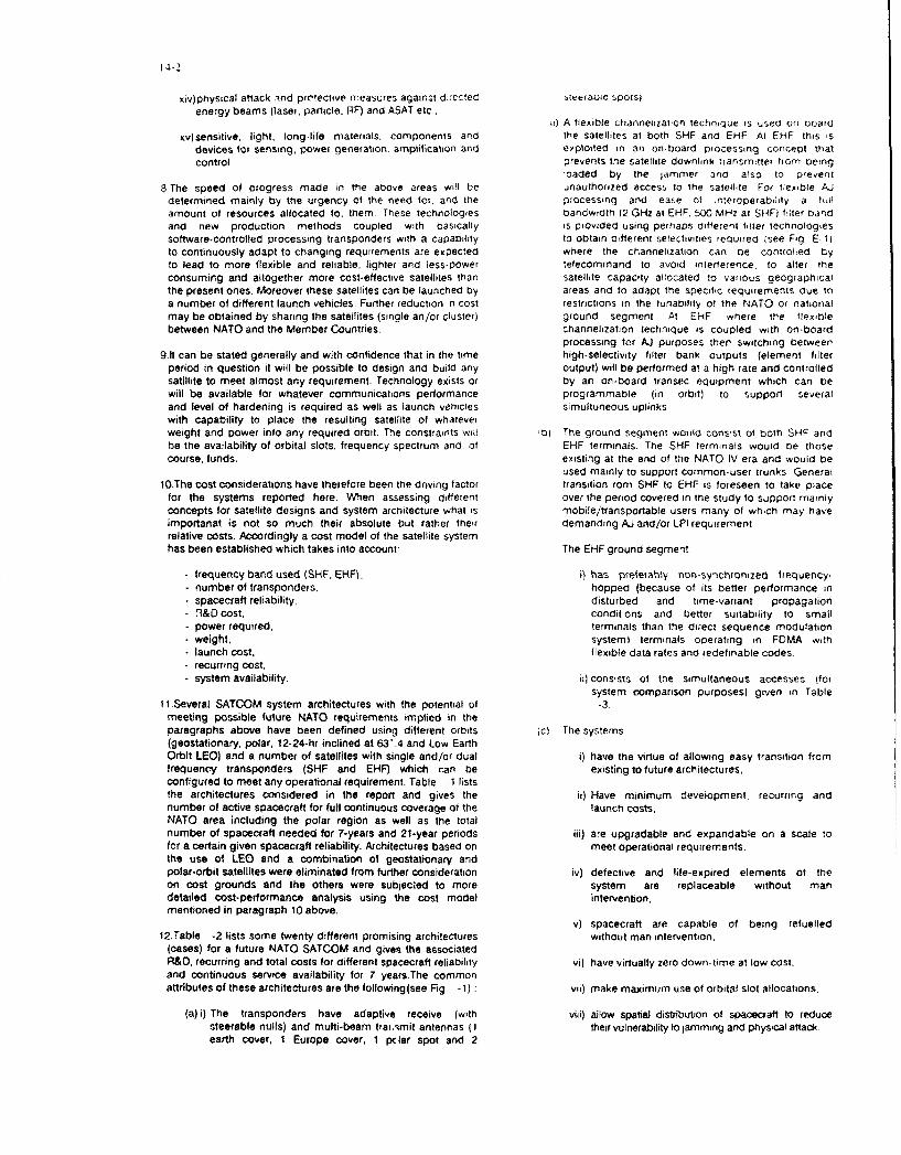
14-2
xiv)physical attack ind protective r,.easLres again~t d:l;cced 'teefaoue spotslenergy beams (laser, particle. RF) and ASAT etc.
ii) A flexible channehizatton technique is u;ed ori board
xv)sensitive, light, long-life materials, components and the satellites at both SHF and EHF At El--F this isdevices for sensing, power generation. amplification and exploited in an on-board ptocessing concept tnatcontrol, prevents the satellite downhnk transmitter from being
loaded by the jammer and also to prevent
8 The speed of progress made in the above areas will be unauthorized access to the satellite For tlexible AJdetermined mainly by the urgency at the need for, and the processing and ease of *nteroperaniiity a lull
amount of resources allocated to, them These technologies bandwidth (2 GHz at EHF. 50G MHz at SHF) filter bandand new production methods coupled with basically is provided using perhaps different fitler technologiessoftware.controlled processing transponders with a capability to obtain different selectivities required (see Fig E 11)to continuously adapt to changing requirements are expected where the channehization can be controlled byto lead to more flexible and reliable, lighter and less-power telecommand to avoid interference, to alter tieconsuming and altogether more cost-effective satellites than satellite capacity allocated to various geographicalthe present ones. Moreover these satellites can be launched by areas and to adapt the specific requirements due toa number of different launch vehicles. Further reduction in cost restrictions in the tunability of the NATO or nationalmay be obtained by sharing the satellites (single an/or cluster) ground segment. At EHF. where the flexiblebetween NATO and the Member Countries. channelization technique is coupled with On-board
processing for AJ purposes then switching between9.1t can be stated generally and with confidence that in the time high-selectivity filter bank outputs (element filter
period in question it wilt be possible to design and build any output) will be performed at a high rate and controlledsatillite to meet almost any requirement. Technology exists or by an on-board transec equipment which can bewill be available for whatever communications performance programmable (in orbit) to support severaland level of hardening is required as well as launch vehicles simultuneous uplinkswith capability to place the resulting satellite of whateverweight and power into any required orbit. The constraints wull 01 The ground segment would consist of both SHF andbe the availability of orbital slots, frequency spectrum and. of EHF terminals. The SHF terminals would be thosecourse, funds. existing at the end of the NATO IV era and would be
used mainly to support common-user trunks General10.The cost considerations have therefore been the driving factor transition rom SHF to EHF is foreseen to take place
for the systems reported here. When assessing different over the period covered in the study to support mainlyconcepts for satellite designs and system architecture what is mobile/transportable users many of which may haveimportanat is not so much their absolute but rather their demanding AJ and/or LPI requirementrelative costs. Accordingly a cost model of the satellite systemhas been established which takes into account: The EHF ground segment.
frequency band used (SHF. EHF). i) has peetrably non-synchronized frequency-number of transponders, hopped (because of its better performance inspacecraft reliability, disturbed and time-variant propagation9&O cost, conditions and better suitability to smallpower required, terminals than the direct sequence modulationweight, system) terminals operating in FOMA withlaunch cost, flexible data rates and redefinable codes.recurring cost,system availability. ii) consists of the simultaneous accesses lfor
system comparison purposes) given in TableI1 .Several SATCOM system architectures with the potential of -3.
meeting possible future NATO requirements implied in theparagraphs above have been defined using different orbits tcl The systems(geostationary, polar, 12-24-hr inclined at 63'.4 and Low EarthOrbit LEO) and a number of satellites with single and/or dual i) have the virtue of allowing easy transition fromfrequency transponders (SHF and EHF) which r-an be existing to future architectures,configured to meet any operational requirement. Table -1 liststhe architectures considered in the report and gives the ii) Have minimum development, recurring andnumber of active spacecraft for full continuous coverage of the launch costs,NATO area including the polar region as well as the totalnumber of spacecraft needed for 7-years and 21-year periods iii) are upgradable and expandable on a scale tofor a certain given spacecraft reliability. Architectures based on meet operational requirements.the use of LEO and a combination of geostationary andpolar-orbit satellites were eliminated from further consideration iv) defective and life-expired elements of theon cost grounds and the others were subjecied to more system are replaceable without mandetailed cost-performance analysis using the cost model intervention,mentioned in paragraph 10 above.
v) spacecraft are capable of being refuelled12.Table -2 lists some twenty different promising architectures without man intervention,
(cases) for a future NATO SATCOM and gives the associatedR&D, recurring and total costs for different spacecraft reliability vi) have virtually zero down-time at low cost,and continuous service availability for 7 years.The commonattributes of these architectures are the following (see Fig. - 1) : vii) make maximum use of orbital slot allocations.
(a) i) The transponders have adaptive receive (with viii) allow spatial distribution of spacecraft to reducesteerable nulls) and multi-beam trai.,mit antennas (I their vulnerability to jamming and physical attackearth cover, I Europe cover, 1 pcIlar spot and 2

14-3
It should be noted that the data ir, Tables -2 (a) and architectures. it can be concluded that(b) are for a 7-year period. During the 21-year totalperiod, three stages of complete space segment r Provided NATO can accept the coveragereplacement are expected to occur, which would allow provided by a geostationary only system offor an update for changes in traffic or other satellites, Architecture A is the lowest costrequirements. For dual frequency systems solutiondevelopment cost will be incurred at each stage.Singlefrequency systems will not incur such costs since the ii) If polar coverage obtained by leasing from thesame designs of spacecraft would be used throughout USA. costs less than Cost (H.A) or Cost (I-A)the 21-year period; only the mix of EHF and SHF types then Architectures A or 8 plus Polar leasingwould change. Provided military components are used would provide the next lowest cost options.in the design of the spacecraft it should be possible to Option B gives improved availability and AJmaintain full availabilty over the 21-year interval, capability but at 33 % higher cost than the cost
of A
13.An examination of the data shows that:iii) The lowest cost architecture which provides full
a) For geostationary operations the cost of coverage is Architecture H at a cost increase ofinterconnection of spacecraft is of the order of 3 % , 50 % over geostationary only (Case B).and is not more than 4.5 % for the inclined orbits(Tundra as the most expensive case).lnterconnection iv) For a further 5 % increase in cost, anprovides significant improvement in service availability improvement from 0.95 to 0,98 in operationalprobability, ranging from 0.14 at the lower inherent availability and an enhanced AJ capability canspacecraft probabilities to 004 at the high end. be obtained by using Architecture 1. This
architecture is probably the most cost-effectiveb) Increasing the space segment availability by the option of those considered, to all of the
amount given in (a) above without, however, using assumed future NATO requirements.Inter-Satellite Links ISL would require launching moresatellites and this would increase the system cost by 15 It is likely that cost will be the driving factor in determining theabout 25 %. hoice of a future SATCOM architecture and it is therefore
appropriate to consider the three dominant cost factors (R&D,c) Operation in inclined orbits costs about 50 % more replacement and launch costs) and indicate what steps could
than the geostationary case for the same service be taken to bring about cost reduction in each case.availability, but gives full NATO coverage including thepolar region. -A) Economy in R&D costs could be obtained through
NATO/National collaboration and by adopting ad) The geostationary case 1 corresponds to the NATO IV modular approach to system eversification and
satellite as far as coverage and the number of evolution. An effective way of achieving the lattersatellites and reliability are concerned. It is interesting would be to develop at the outset separate SHN andto note, however, that the 7-year system cost of Case EHF spacecraft and use them, in GEO and TUNDRA1 and that of NATO IV (about 400$M) are almost orbits alike, in a mix determined by the changingidentical even though Case 1 satellites have requirements,considerably more capacity (in SHF and EHF) andsignificantly greater resistance to jamming (on-board b) The use of smaller spacecraft, even though more ofsignal processing in EHF and adaptive nulling them may be needed, could lead to lower systemantennas), costs because of the economies of scale. Such
economies of scale would be further enhanced rf thee) The system cost changes significantly with the 7-year same spacecraft types are used at all stages of system
service availability probability. How many satelittes evolution over a period of. say, twenty years. They willwould be needed for a 21- year period without having also be enhanced if the same spacecraft types areexcessive capacity would depend on this as well as on bought for national as well as NATO use.what residual capacity would remain at the end ofeach seven-year period and how the change in c) Launch costs can be minimized by reducingrequirements is introduced- abruptly at each 7-year spacecraft mass, in particular through the exploitationperiod or progressively during the 21-year period. In of new technology. It is also important to maximizethe latter case, some reduction in the total number of compatibility with the largest possible range of launchsatellites required and hence in total cost would be vehicles.expected.
d) Interconnection of spacecraft increases system14.The architectures which appear cost-effective and promising reliability and therefore tends to reduce the total
are given in Tabie -4. number of spacecraft that need to be launched.
The following comments can be made about these e) Finally, long-term planning is the key to achievingarchitectures: reductions in both R&D and recurring costs.
a) An adequately wide range oef architectural options 16.The NATO SATCOM systems so far acquired have beenare presented from which the architecture best suited based on national developments adapted to NATOto the requirements, as they will be known nearer the requirements and the continuity of service (not necessarily fulldate of system implementation, can be selected. service ) has been obtained by sharing or borrowing capacity
from national systems. The national systems, in turn, haveb) Based on the assumptions made regarding possible relied for continuity of service on the availability of capacity on
future NATO requirements, reliabilities of future the NATO system. Each procurement has contained anelectronic systems and costs per kilogram of important element of R&D costs and since successive systemsPayloads, Spacecraft Platforms and Launches which have been developed almost independently of each other.have been used consistently for all of the candidate R&D costs have been, like the replacement cost, also recurring

14-4
There has been a minimum of joint national R&D and use of are common to military and civilian satcoms some
the system and each procurement has been preceded by others which are specific to military, are likely tO belengthy negociations on production sharing which has not, in common to both national and NATO systems and yetgeneral, satisfied, at least, some of the member countries. As a another category of topics will oe NATO-specific itresult of having independent NATO and national systems there would therefore be necesarry to make a more detailedhas been considerable interoperability problems assessment of the R&D topics and determine where
R&D is a prerequisite and either can be relied uponIt is believed that this trend, based on successive lumps in present/future civilian developments or carried outspending and capabilty with a minimum degree of general jointly by member nationsnational participation should be and can be changed to meetthe needs of the coming decades which may be characterized 18.The following areas appear as lrst candidates for a NATOby uncertainly and shrinking military budgets requiring R&D effort because they would provide solutions to problemsaffordable and flexible systems. which are NATO-specific and can be made available within tIe
time-frame considered for NATO SATCOM systemsThe member countries have adequate experience within NATOand Europe and know that under these circumstances it is a) On-board flexible anti-jam signal processing whichnecessary to resort to joint R&D, procurement and use of the can be controlled by software to meet AJsystem while ensuring effectiveness and competitiveness for requirements generally and to adapt to nationalkeeping the costs down. modems and new modems introduced during the
lifetime of the satelliteIs)17 What needs to be done jointly are:
b) Adaptive nulling AJJ receive antennas tailored to NATOa) To define NATO and national requirements for satellite needs and to keep costs down
communications.cl Autonomous control of the spacecraft and O&M
b) To develope and agree on a system architecture generally using techniques of artificial intelligence.neural networks and roootics
c) To delineate those technological areas which arecritical and require R&D. By sporing R&D activities, limited to payload technology, in the
member nations even on modest scale. NATO can expect tod) To encourage and support companies and R&D get a better insight into and to make an impact on current
establishments to form research partnership for technology developments carried out for civilian and militarydevelopment and production to be carried out in a purposes.competitive manner.
19i.t is believed that the collaborative approach outlined aboveIt is believed that the architectures evaluated and for SATCOM acquisition in NATO give tasks to all the existingrecommended in this report form a good foundation bodies in NATO such as NACISA. STC. ORG, IEPG, AGARD.for (b) above and ensure also that the satellite designs etc.. and would probably not necessitate creating newoutlined that are flexible need not change basically structures. Cost and benefit anlysis carried out in the reportover a period of some twenty years or longer thus show that the architectures recommended can bekeeping the R&D and recurring costs to a minimum. implemented in the manner suggested above and could lead
to systems which are considerably cheaper and much moreThe report outlines also certain critical technologies for effective tha, those we have had so far(c) above which need R&D. Some of these R&D topics
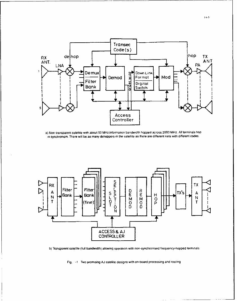
STransec
Code (s)
ANT. LNA ' PA ANT
4A-
5L
a) Non-transparent satellite with about 50 MHz information bandwidth hopped across 2000 MHz. All terminals hop
inl synchronism. There will be as many dehoppers in the satellite as there are different nets with different codes.
Fi g 1t w ro sitn a
B ank E n c I
5L
Acces
a) Nntransparent satellite ulanwidth ablout5wMzingfoprmation bnwidth n-ynhropped acrossuen0cy~-hpA" terminals ho
insynchro ism. Ther wil berosm asny AJ o p rsi h satellite de ig s w th er n ar ed iffroessn t net routhi ffrntgod s

14-6,
TABLE -1Number of Satellites
Required for different SATCOM Architectures
Features No of Active S/C Comment No of S/C Total No offor full continuous for 7 years S/C for
Architecture Coverage 21 years
(a) Proliferated LEO 240 > 240 > 500
(c) Inclined Elliptical Orbit
(cl) LOOPUS 9 27 81
(c2) MOLNIYA 3 x 12 - hrs 9 27
2 x 24 - hrs 6 18
(c3) TUNDRA 2 x 24 - hrs 6 18
(d) GEO 1 Baseline 3 9
(e) Systems of Satellites in more than one Orbit
(el) GEO + Polar 1 GEO + 6 Polar S/C in GEO are 3 GEO 9 GEO
dual frequency single + +
in Polar orbit 18 Polar 54 Polar
(e2) GEO +24-hr MOLN IA
(a) Dual freq S/C in 1 GEO GEO S/C have 3 GEO 9 GEO
GEO+single in + 2 inclined EHF and SHF + +
Inclined Orbit Inclined EHF or SHF 6 inclined 18 inclined
(b) Single freq in 2 GEO GEO S/C are air 6 GEO 18 GEO
both orbits + 2 inclined of EHF and SHF + +
Inclined EHF or SHF 6 inclined 18 inclined
(f) CLOUDSAT Receive S/C Numbers wil depend 60 GEO 180 GEO
with 10dB ECCM 20 GEO. 20 Inc. on jamming threat 60 Inclined 180 inclined
advantage TX S/C:- at the time 6 GEO 18 GEO
relative to (e2)b 2 GEO+2 Inc 6 inclined 18 inclined
(g) MEWS The basic concept applies to all case (c) thro' (f)
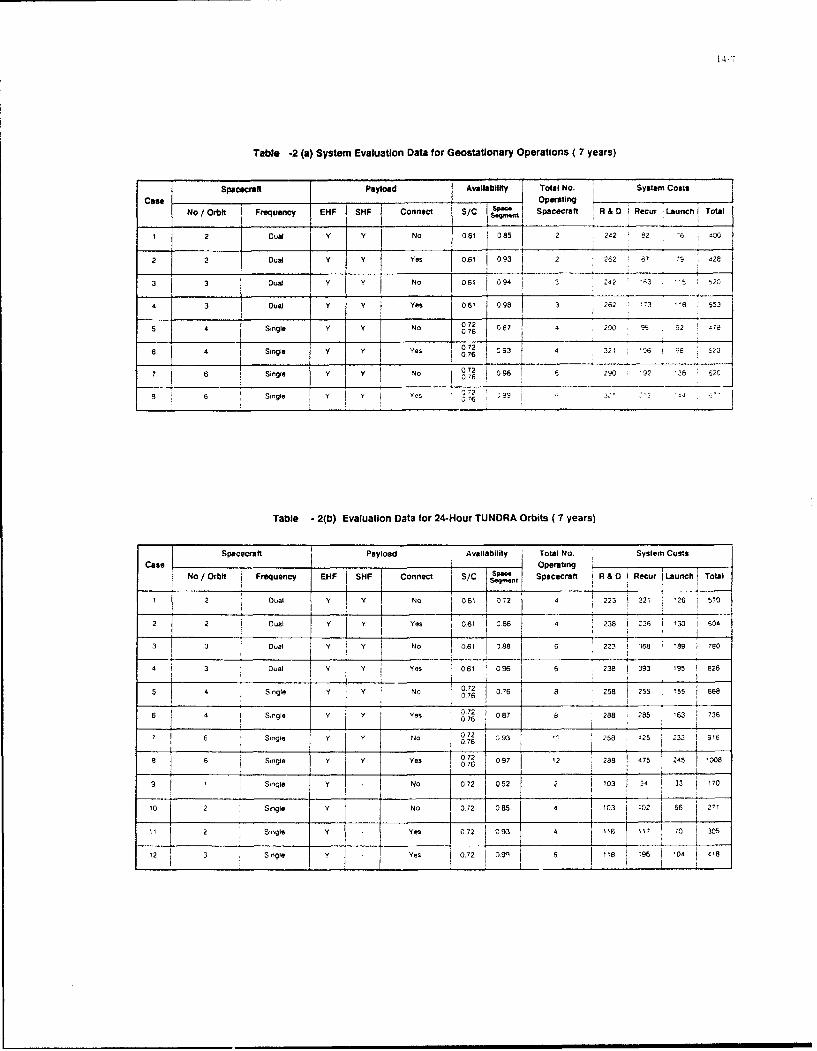
14-7
Table -2 (a) System Evaluation Data for Geostatlonary Operations ( 7 years)
Spacecraft Payload Availabilty Total No. Systam CostsCas =eI Operating
No/Orbit Frequency NHF sHF Connect S/C i Sp-me Spacecraft R& D Recur i Launch Total__ _ _I _ _ _ _ __ __ _ _ _ __ _ _ _ _ _
2 Dual y Y No 060 085 2 242 ý2 ? 6 i ,
2 2 Oual Y Y Yes 0.61 093 2 262 d7 -9 426
S 3 Dual y Y No 061 094 1 3 42 ";3 1-t
3 DuaJ y y Yes 06,1 098 3 262 '73 '8 553
5 4Single Y y I o08 90 32 478
6 4 Sine Yes 02 093 4 32 M 6 5230 6 g0
SY No 072 6096 290 '92 2 -9 26 Single Y 0 762 -
6 6 Single 2 e 076D ' ~ 22 i
Table -2(b) Evaluation Data for 24-Hour TUNDRA Orbits (7 years)
Spacecraft Payload Availability Total NO. System CostsCase___ OperatingNof Orbt Frequency EI4F 1SHF I Connect SyC Spa- DRcr oa
rb I ~~eq~ Spacecraft ft&0IRcrLaunchToa
2 Dual 9 y No 0.1 0721 4 2232 1 " 26 570
t IJ I0 7
2 2 Dual Y V Yes 0.6 086 4 238 1-6 1 30 604
3 3 Diual V Y No 061 089 6 221 1 368 689 790
4 3 Dual Y ()6 096e 6 2381393 '95 626
- 4 4 { I. ________
Single V No 072 0ý76 8 i 58 5 1S i551668
Single Y Yes 8 86 288
7 1 62 9g. V Y No 072 7 9 323 Z 9,62Y YC 07 6 4 238 2
Single Y I Yes 6 1 8 10721?~ ~ t076~5t 0
9_ .1 Single YNo 072 03 . ..70
11 2Single Y No 1072 085 4 03 1 102 66 211
4 2 Single .ZY Y Yes 072 093 6 8 96 '9 02
12 _ _ i _ _ _ _ _ _ I t ___ 0
1g 3 Sog Y NoYe 072 05229 3 34'33 ••

14-8I
Table -3: The EHF Ground Segment Assumed for System Comparison
Type of Antenna T. . Transmission Number of simul -Terminal Dia. (in) .'N1 Rate (Baud) taneous accesses
Ship- Borne 1.0 0.1 2400-9600 20
Aircraft 0.5 0.1 2400 10
Submarine 025 0 1 100-240)0 1
Land transportable 50 10 4x6001
2.0 05 4 x2400 30
MFn-pack 0.5 [0.01 75 30
()16 1(Z/s cooecs (adaptive Sub-band coding) exist today with quality which equals that of the 64 kb/s PCMV It is expectei3 that in the
1llrneframe considered In this report there will be 8 kb/s or even lower - rate codecs available for use in SATCOM with qualities comparable
to that of 64 Xb/s PCM voice
TABLE - 4
COST-REUIABILITY COMPARISON OF CANDIDATE ARCHITECTURESFOR A SYSTEM LIFETIME OF 21 YEARS
Cases No Total No of No of Payload Orbit /Freq. Service Cost (21-year) (sm)
Architecture operating - -Availability
T GEO spacecraft EHF SHF T GED R&D0 Recur. Launch Total
A - 1 2 2 2 - D 085 2,4 1,2,33- 200726 246 228
6 - 0 08 326Z - 31.73- 3. 118-786 !i9 354
c 2 - 4 I4 0 086 3,3 3.4 6 -a '90
D 4 - 6 6 K' o 1- 096 3 238-3 393 195 2478865
E 6 - 8 4 14 E.S 1087 288 950- 2: 40- 6 2219,15 : ~ 99
F 812 6 6 E.S 097 288 6 5 '34 2637
G 12 3 E 097 118-7866- 665 - 5 9 313.354.904 44 647
H 12 7 i2 9 3 E ES 052152 -- 28
1 12 6 12 9 I3 E E ES 0396 32096 %, '43 2
!8 9 6~ E' 9 366 2 c

16-1
ADVANCED TECHNOLOGIES FOR LIGHTWEIGHT EHF TACTICALCOMMUNICATIONS SATELLITES*
David R. McElroy, Dean P. Kolba, William L. Greenberg, and Marilyn D. SemprucciLincoln Laboratory, Massachusetts Institute of Technology
P.O. Box 73Lexington, MA 02173-9108 - USA
1. ABSTRACT variation in beamnwidth can be achieved, while 19 uplinkThe communications capabilities provided by EHF satel- feeds give a 5-to-I variation. By incorporating both phaselites can range from low data rate services (75 to 2400 bps and amplitude control in the beamforming network andper channel) to medium data rate links (4.8 kbps to 1.544 including a processor, the variable beamwidth antenna canMbps per link) depending on the payload configuration. also include autonomous nulling [5].Through the use of EHF waveform standards, the EHFpayloads will be compatible with existing and planned 4. LIGHTWEIGHT SIGNAL GENERATORSEHF terminals. Advanced technologies permit the devel- In order to provide effective interoperability, it is impor-opment of highly capable, lightweight payloads which can tant for all the EHF payloads to work with the same typebe utilized in a variety of roles. The key payload technol- of user terminals. Standard EHF transmission formats andogies include adaptive uplink antennas; high speed, low dynamic access/configuration control are important fea-power digital signal processing subsystems; lightweight tures in providing this interoperability. The standard EHFfrequency hopping synthesizers; and efficient solid-state waveform requires the dehopping and demodulation oftransmitters. The focus in this paper is on the signal communications signals on-board the satellite. As shownprocessing and frequency generation technologies and their in Fig. 2, lightweight frequency hopping synthesizers canapplication in a lightweight EHF payload for tactical be implemented using direct digital synthesis techniquesapplications, along with high-speed, hybridized bandwidth expansion
circuitry. These advanced frequency generators yield2. INTRODUCTION almost an order of magnitude reduction in weight overA motivating factor for the transition to EHF communica- frequency synthesizer subsystems of the early 1980's whiletions (i.e., 44 GHz uplinks and 20 GHz downlinks) is the also requiring significantly less than half the power.requirement for improved interference protection withsmall mobile and transportable terminals for tactical and The key design criteria for a payload frequency synthesizerstrategic users. Emerging technologies allow EHF corn- are a low power configuration which has the ability tomunications systems, which can support both low data rate generate signals with low spurious frequency content while(LDR) and medium data rate (MDR) services, to be imple- meeting the frequency switching speed requirement. Thesemented in lightweight, low power configurations. Stan- factors are key in selecting the bandwidth expansiondard EHF payloads, utilize both advanced antenna systems approach as shown in Fig. 3. A switched filter bankand on-board signal generation and processing techniques approach is a straightforward implementation. However,to improve performance and protection. A payload which filter size limits the number of frequencies (N) which canutilizes these features for a theater coverage application is be selected for mixing with the direct digital synthesizerdescribed in this paper. The application of advanced (DDS) output, thus impacting the amount of bandwidthsignal generation and processing technologies to this light- which must be generated by the DDS. This adverselyweight payload result in a payload which can be incorpo- affects both the power and spur constraints by requiring arated into satellites of many sizes, ranging from large, higher power DDS and by generating larger spurs. Themultiple function satellites to small, augmentation satellites alternative approach shown in Fig. 3 was selected for the[1-4]. payload frequency synthesizer. This approach utilizes a
high speed phase-locked loop to generate the set of N3. ANTENNA OPTIONS frequencies which are mixed with the DDS output toAdvanced antenna features for tactical applications can expand the bandwidth. The wide bandwidth of the loopinclude the ability to provide a variable coverage uplink allows N to be large, thus requiring a smaller DDSspot beam pattern, an autonomous nulling capability within bandwidth. The reduced DDS bandwidth allows the usethe uplink spot beam pattern, or both. Variable beamwidth of a low power, CMOS based DDS and results in lowerEHF antennas can be utilized in a variety of applications spur levels. The key technology challenges in implement-as shown in Fig. 1. For payloads in elliptical orbits, a ing the wide bandwidth loop are the high-speed countervariable beam width feature can be utilized to maintain an and the custom voltage controlled oscillator (VCO).essentially fixed coverage area independent of satellitealtitude [4]. In a geosynchronous orbit application, the Some of the test results from a breadboard synthesizerbeam variability can be used to satisfy different coverage which utilizes the wide bandwidth loop for bandwidthand gain requirements such as in supporting tactical expansion are shown in Fig. 4. The breadboard synthesiz-theaters of varying size and capacity requirements. One er meets the switching speed requirement by settling toapproach to obtaining the beam variability is by employing within 7.5* of the final phase in a little over 0.8 gisec.multiple feeds in the antenna. These feeds are combined The goal for spur levels is also met by the breadboardwith a variable power combiner network before going to synthesizer, A typical output spectrum is shown in Fig. 4.the receiver. With 7 uplink feeds in the antenna, a 3-to--I
5. HIGH-SPEED SIGNAL PROCESSORS*This work was sponsored by the Department of the High-speed digital signal processing advances can be uti-Army, the Department of the Air Force, and the Defense lized to provide lightweight, low-power demodulators andAdvanced Research Projects Agency under Air Force signal processing subsystems capable of supporting manyContract F19628-90-C-0002. LDR and MDR channels. In the early 1980's. the use of

16-2
combined analog and digital processing technologies 6. EXAMPLE EHF PAYLOAD FORprovided the most efficient implementation '(-r demodulat- GEOSYNCHRONOUS ORBITSing the LDR uplink waveform. As shown in Fig. 5. the An example ElF payload, which utilizes a pair of variablefrequency demodulation was performed by a surface beamwidth spot beam antennas and both LDR and MDRacoustic wave (SAW) demodulator followed by a digital signal processing, is shown in Fig. 9. For this examplecommunications and acquisition processor. Now however, payload, the uplink spot beam antennas utilize 7 feedsthe progression of digital technology has advanced the each and the downlink beams are formed using I feedstate-of-the-art to the point where an all digital approach each. Both LDR and MDR channels are supported in theis more efficient. The development of application specific spot beams. In addition, the payload provides LDR earthICs (ASICs) which process the standard EHF waveforms coverage service through a pair of earth coverage horns.will contribute significantly to the reduction in weight and The LDR processor supports 16 communications channelspower required by these subsystems. For further reduc- in each of the beams using the El-IF common transmissiontions in weight and power, the ASIC devices can be format. The MDR processor provides a total of 4 chan-integrated into multi-chip modules to achieve the benefits nels of service in the spot beams with any mix betweenassociated with a wafer-scale level of integration as shown the two beams.in Fig. 5. In this comparison of an LDR signal processorusing multi-chip modules with an LDR signal processor The main considerations in selecting a spot beam size arefrom the early 1980's, an order of magnitude reduction in the required gain and the coverage area provided by theweight is obtained while the power is decreased by more beam. The 10 to 30 spot beam size in this example pay-than half for the same number of channels processed. load, along with the 6 W solid state transmitter, will
support 2.4 kbps service to a small terminal (2'/2W) whileThe digital Fast Fourier Transform (FT) demodulator is in the wide beam mode and will support I Mbps links toimplemented with two ASIC designs shown in Fig. 6. The a medium size terminal (4'/12W) while in the narrowsampled signals are first preprocessed before the actual beam mode. The payload in Fig. 9 is estimated to weightransform is performed. In this FFT preprocessor chip, the about 200 lb and require about 290 W (these estimates in-signals are windowed, coherently integrated for adjustment clude 20% margins).of frequency sample spacing, and stored in memory. Theheart of the demodulator is the in-place FFT chip shown The 6 W transmitter and the 20" spot beam antennasin Fig. 6. The data is stored in memory, the FFT butterfly provide sufficient EIRP to support both LDR and MDRoperations are performed, and after the transform is links in a variety of modes and data rates with the totalcompleted, the I and Q samples are converted to magni- throughput for the payload depending on the mix of LDRtude values for further processing by the uplink processor. and MDR terminals in a scenario. An example loadingThe FF'T chip is designed for use with data or acquisition scenario is shown in Fig. 10. For this example, threechannels and car, perform a transform of up to 256 points, types of terminals were assumed: a 6', 25 W ground
terminal; a 4', 12 W transportable terminal: and a 2', 2 WThe ASIC for the in-place FFT, shown in Fig. 7, has been portable terminal. The ground terminal is supported by thedesigned, fabricated, and tested. The FFT ASIC is earth coverage beam in the example. The portable anddesigned to meet the primary requirements for a space transportable terminals are supported in the spot beams.application: radiation hardness, high performance, low One of the spot beams is set to a 3' beamwidth (aboutpower consumption, and high reliability. A significant 1200 mile diameter coverage at the subsatellite point)design feature in this chip which enables high performance while the other spot beam is set to a 1' beamwidth (aboutin a low power configuration is the use of on-chip memory 4W0 mile diameter coverage at the subsatellite point). In(RAM and ROM) for the data being processed and for the This example, 27 LDR networks and 17 MDR links arecoefficients used in the FFT. The amount of memory supported for a total payload throughput of 3277 kbps.required is minimized by employing an innovative in-placealgorithm using dual port RAM. A range of payload capabilities can be implemented using
the variable beamwidth antennas, nulling processors. andThe FFT chip, the preprocessor chip, and a communica- the other key technologies described briefly in Fig. I andtions uplink processor (CUP) ASIC can be configured into 2. These technologies can be used to implement smalla communications demodulator, which is capable of EHF payloads as in the example presented here. However,processing up to 16 channels, as shown in Fig. 8. These the same technologies can also be used in secondary anti-ASICs, along with the supporting chips (A/D converters, jam payloads or multiple function anti-jam payloads onCUP RAM, and mission ROM) can be packaged into a large satellites as shown in Fig. 11. In addition, many ofmulti-chip module which is about 2" x 3" in size. the same signal processing and frequency generation
technologies are applicable for improving EHF terminalsFor MDR channels, similar ASIC technology is expected as well.to yield efficient implementations for these higher data ratechannels as well. A preliminary design for a four channel 7. SUMMARYMDR subsystem requires three individual ASIC designs. A key feature for the flexible use of the EHF payload is toFour demodulator chips are utilized in conjunction with a provide the ability to configure the payload to provide aclock generator chip and an MDR processor chip to form variety of services. Supporting either LDR, MDR, or boththe four channel MDR subsystem. The designs for the types of channels in a variable beamwidth antenna helpsclock generator chip and the MDR processor chip allow provide this son of flexibility to meet a broad range ofcascading to support additionai MDR demodulators for user requirements. Development of the critical technolo-payloads with more than four channels. gies for use in these types of payloads has been initiated.
The technology areas include variable beamwidth antennas,lightweight frequency synthesizers. and high speed signalprocessors for both LDR and MDR channels.

16-3
8. ACKNOWLEDGEMENTSThe concepts which are presented heme were developedthrough the MILSATCOM concept and technologydevelopment efforts of the lightweight EHF payloadprogram at MIT Lincoln Laboratory. We thank theindividuals who have contributed to this work. Weespecially thank John Drover for his work in developingthe FF1' ASIC and David Maternat for his work in leadingthe design of the frequency synthesizer.
9. REFERENCESI1. D. P. Kolba, L. L. Jeromin, D. R. McElroy, and
L. N. Weinerý 'Complementary Robust MILSATCOMService: A Significant Role for Lightweight Space-craft," Project Report SC-79, MIT Lincoln Laboratory(28 March 1989).
2. D. R. McElroy, D. P. Kolba, M. D. Semprucci,"Small EHF Military Satellite Concept for Augmenta-tion and Restoral," in AIAA 13th Int. Comm. Sat.Systems Conf., Los Angeles, CA, (I11- 15 March1990).
3. D. P. Kolba, William L. Greenberg, D. R. McElroy,and M. D. Semprucci, "Advanced EHF Technologiesfor Light- weight Augmentation / Restoration Com-munications Satellites," in 40 AI4AAISU Conferenceon Small Satellites, Logan, Utah, (27-30 August1990).
4. D. P. Kolba, D. R. McElroy, and W. C. Cummings,"Lightweight EHF Satellites for Augmentation ofAnti-Jam Comrntunications," in 1 4 1h AIAA Interniation-al Communication Satellite System Conference.Washington, DC. (22-26 March 1992)
5. D. R. McElroy, W, C. Cummings. and D. P. Kolba."Lightweight Adaptive Antennas for EHF Payloads,"in MIILCOM '92, San Diego, CA, (11-14 October1992).
DARABOLIC
EEI+ -InýHEX A47ONA~ SEAM FEEDCONFIGURATION
To POWER
PECkHVE; COMNINER FA
QEOSYNCHRONOUS ORBITS 0 FEEDS FOR 3 VARIATION. ELLIPTICAL OPBIrS
SATISFY VARYING COVERAGE. 19 FEEDS FOR 5 VARIATION MAINTAIN rIXE-0C'tR;
GAIN REQUIREMENTS JREA INDEPENDENT nF&IMPLEMENTATIONS CAN INCLUDE. SATELLITE ALTITIJDE
NULL IN G
Figure 1. EHF Variable Beamwldth Antenna

Figure 2. Frequency Synthesizer Reductions
SWITCHED FILTER BANK PHASE-LOCKED LOOPFILTER REFERENCE
BANK FREQUENCY
8 SINGLE PHASE 00 URT
j FRO DEýTECTOR FLE ou
DRIVE COUTT
'<F Fa-E
CONTROLRO 4R
"* STRAIGHTFORWARD IMPLEMENTATION - LARGE N - SMALLER ODS 8W
"* MMIC SWITCHES: SMALL/LOW POWER - LOWER POWER DOS- SMALLER SPURS
"* FILTER SIZE LIMITS N - LARGER DDS 8W -LRELO ADIT- HIGHER POWER DDS *LRELO ADIT- LARGER SPURS - VERY HIGH SPEED COUNTER
- POWER PENALTY
-CUSTOM VCO
Figure 3. Bandwidth Expansion Implementation Options

16-5
SYNTHESIZER PHASESETTLING TRANSIENT(Max to Min Frequency)
7 50
-200 800 1800
TIME (ns)
TYPICAL OUTPUT SPECTRUM10
46 dB-J I,W -30> I GOAL -40 dB
w -50Uj
0.- 70
-90 I
10.075 10.085 10.095
FREQUENCY (GHz)
Figure 4. Breadboard Synthesizer Performance
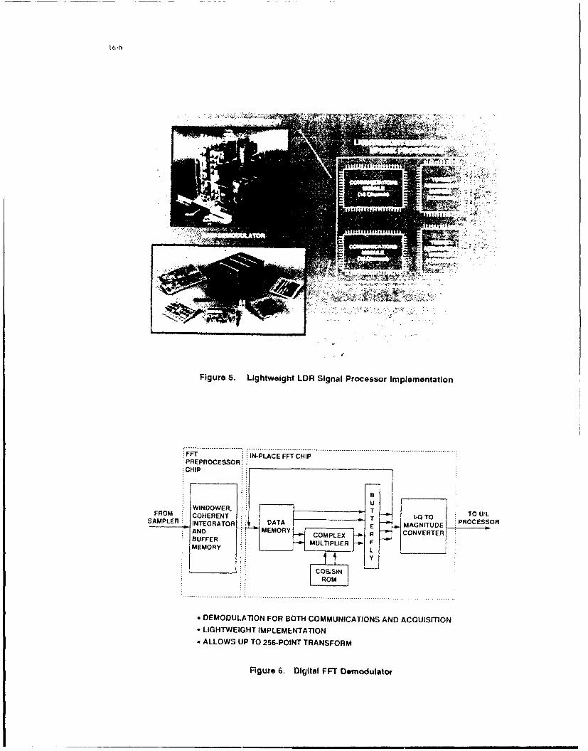
Figure 5. Lightweight LDR Signal Processor Implementation
FFT :.IN-PLACE FF1 CHIP:PREPROCESSOR::
SMLR INTEGRATOR DAAE MAGNITUDEANDMEMRY COMPLEX R CON VERTER}
BUFDEMOUATO FRBTCOMUNTICATION ANF CUSTOMEOR LIHWIH LMLMNTT
* ALOWS P TO256-OINTTRANFOR
Figre . ~gial F1Demdulto
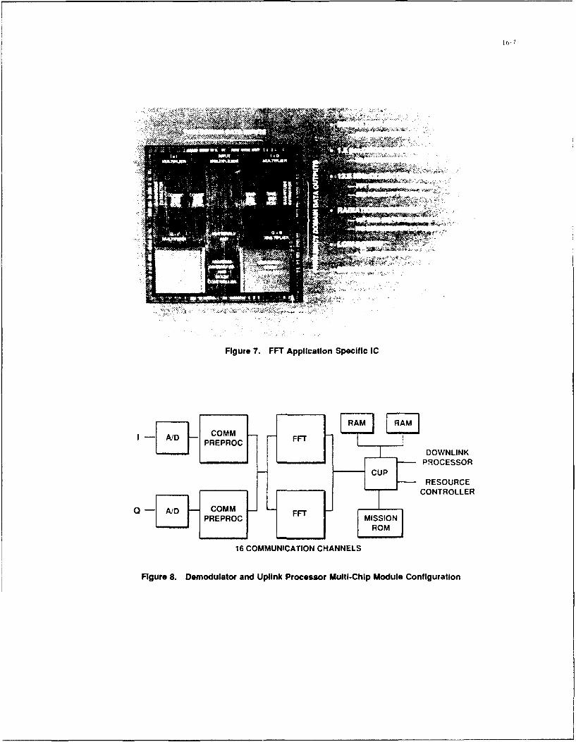
Figure 7. FFT Application Specific IC
PREPROC DOWNLINK
PROCESSOR
RESOURCECONTROLLER
Q Com _COM FFT _PREPROC MISSION
ROM
16 COMMUNICATION CHANNELS
Figure 8. Demodulator and Uplink Processor Multi-Chip Module Configuration

16-8
GEOSYNCHRONOUS ALTITUDE ORBIT
VARIABLE BEAMWIDTHANTENNAS
1.0-3.0 deg "O 2.0 deg (HPBW)
U/L R D/L SPOT BEAMS
SPOT BEAM PROCESSOR
1.0-3.0 deg LDR 48 LORU/L RCR CHANNELS
SPOT BEAM 6 W SSPA
4MOR DPSK TX S
CHANNELS w.TS
EARTH LDRCOVERAGE RCVR
U/L EARTH
COVERAGE
SYT. COMMAND,CNRL YNT.
TRANSEC
PAYLOAD SIZING
EHF ONLY -200 lb -290 W
Figure 9. Example LDRPMDR Payload

16-9
EARTH COVERAGE BEAM
GROUND TERMINAL (W, 25 W) I x 2.4 kbPsGROUND TERMINAL (f, 25 W) 4 x 150 bWe
3 SPOT BEAM
PORTABLE TERMINAL (2', 2 W) 4 x 2.4 kbpsPORTABLE TERMINAL (2', 2 W) 6 x 600 bpsTRANSPORTABLE TERMINAL (4', 12 W) 4 x 16 IipTRANSPORTABLE TERMINAL (4', 12 W) 4 x 2.4 kbps
* SPOT BEAM
PORTABLE TERMINAL (2', 2 W) I x 2.4 IdbpsTRANSPORTABLE TERMINAL (4', 12 W) I x 1.024 MbpuTRANSPORTABLE TERMINAL (4', 12 W) 2 x 512 kbpsTRANSPORTABLE TERMINAL (4', 12 W) 4 x 256 kbpsTRANSPORTABLE TERMINAL (4', 12 W) 6 x 16 kbps
TOTALS
27 LDR NETWORKS, 45.0 M"p17 MDR UNKS, 3=222 •kps
Figure 10. Example LDR/MDR Loading Scenario
• MULTIPLE FUNCTION 4I ,11111AJ PAYLOADS -'
/
/ -/•'
/ .SMALL SATELLITES/ ,FOR AUGMENTATION
RESTORATION OFAJ SERVICE
*$ECONDARY
WITH SIGNIFICANT
CAPABILITIESIMPROVED EHFTERMINALS
Figure 11. Technology Utility

SYNCHRONIZATION TECHNIQUES FOR MEDIUM DATA RATE EHFMILSATCOM SYSTEMS
G. BoudreauM. Schelter
MPR Teltech LtdSuite 2000, Tower A, 320 Queen Street
Ottawa, Ontario, Canada, KIR 5A3
SUMMARY PDMoD demodulator BERPDMs BER at output of diversity combiner
In the area of MILSATCOM, considerable effort is P," BER of DPSK modulationcurrently being expended on the development of systems PPA(DL) probability of false alarm on DLoperating in the EHF frequency bands and employing PPA(UL) probability of false alarm on ULonboard processing. Two of the principal advantages of P5 probability of overall synchronizationemploying these features are that the MILSATCOM R, hop ratesystem will be capable of increased throughput and will R, coded burst symbol ratepossess increased immunity to jamming and other channel TDMA Time Division Multiple Accessimpairments. Most of the previous research and TOD Time of Daydevelopment in EHF MILSATCOM has concentrated on TDL error in DL timing estimateLow Data Rate (LDR) waveforms, for data rates up to 2.4 T worst case group delay variationkbps. In order to meet the requirements for increased T®.., UL hop timing mismatchthroughput, Medium Data Rate (MDR) waveforms are TUL residual error in UL timingbeing developed. These systems include data rates up to UL uplinkand including T1. This paper examines the constraints thatcommunicating at MDR data rates places on I INTRODUCTIONsynchronization and provides an overview of some of thevarious techniques and algorithms that can be employed As is well known, utilizing the Extremely High Frequencyfor both spatial and time acquizition as well as tracking. (El-IF) band for Military Satellite (MILSATCOM)Both channel and equipment impairments affecting communications offers several advantages over moresynchronization are examined. Robust open and closed conventional military satellite communications bands suchloop acquisition and tracking algorithms are examined in as X-band or UHF. The EHF frequency bands centered atconjunction with onboard processing techniques. 45 GHz on the uplink and 20 GHz on the downlink (DL)Performance is discussed in terms of SNR, acquisition allow the use of higher gain directed antenna beamtime, probability of correct acquisition and probability of patterns, which provides greater immunity to potentialfalse acquisition. Tradeoffs in a MILSATCOM system uplink jammers and allows a greater capacity on thedesign based on various user requirements are also downlink [1]. This is due to the narrower antennapresented. beamwidths that can be attained at EHF frequencies.
permitting the rejection of jammers either through nullSYMBOLS beamsteering or sidelobe rejection. These features are
advantageous in a tactical scenario, in which satellitedB decibel communications coverage is desired for a small theatre ofDL downlink operation. A second major feature that is desirable in aEHF Extremely High Frequency MILSATCOM system is on-board processing at theShop energy payload. This feature prevents uplink (UL) channelE. coded burst symbol energy impairments such as fading or jamming from degradingFDMA Frequency Division Multiple Access the satellite transponder and degrading the downlink asGHz GigaHertz well as the uplink. The majority of current research andGT Ground Terminal development of EHF M1LSATCOM systems has been forkbps Kilobits per second Low Data Rate systems supporting user data rates from 75kHz KiloHertz bps up to and including 2.4 kbps. Such data rates may beL diversity level sufficient for limited voice or low capacity datan. number of downlink TDMA slots communications within a theatre of operation, however.ns nanoseconds higher data rates supporting more robust voiceP,(DL) probability of detection on DL communications and a higher volume of data traffic wouldP,(UL) probability of detection on UL be required for a theatre command center. For such

17-2
scenarios, MDR type data rates up to and including TI Table I: MDR System Parameters
would be required.Speccatio
Synchronization is one of the key areas of l .-centialvulnerability in the design and operation of a UL frequency 44.5 GHz
MILSATCOM system. In order to meet operational DL frequency 21 GHzrequirements, an MDR EHF MILSATCOM system mustprovide a synchronization capability that is at least as UL frequency 2 GHz
robust as the communications capability it supports. bandwidthSynchronization consists of both acquisition and trackingprocesses. These processes involve adjusting the critical DL frequency 1 GHz
parameters of spatial pointing, frequency and timing, at the bandwidth
ground terminal. It will be assumed that the payload is thesystem reference with regard to frequency and timing, and modulation DPSK
that the ground terminal must match its timing and Hopping rate slow frequency hopping
frequency to the DL received signals. Similarly it mustensure that the UL signals arrive at the payload matched Data Rates 32 kbps to TI
in time and frequency to those of the payload. This paperexamines the system design considerations for Processing functions - coding: block or
synchronization of EHF MDR systems utilizing Tactical convolutional
Satellites (TACSATS). The emphasis of the discussion diversity
will be on performance capabilities to meet theatre -interleaving
command requirements. - time permutation
satellite orbits - arbitraryThe paper is organized as follows. Section HI examines .....
some of the system characteristics and assumptions which payload antenna 2* - 5* beamwidthimpact the design of the synchronization process. Sections 26-34 dBi
HI, IV, and V examine the design of spatial, time andfrequency synchronization algorithms, respectively. Section payload amplifier 5 W SSPA
VI examines parameters and performance measures for an
overall synchronization algorithm. Section Vil provides a ground terminal antenna up to 1.8 m
conclusion to the paper. ground terminal up to 20 W
2 MDR EHF SYSTEM CHARACTERISTICS amplifier
2.1 Waveform and Operational Considerations
The assumed key waveform and operational characteristicsthat are pertirent to the discussion in this paper areoutlined in Table I. These characteristics were consideredby the Canadian Department of National Defence for the
current MDR EHF MILSATCOM system design 12]. Asdiscussed above, the uplink bandwidth is 2 GHz centeredabout 44.5 GHz, whereas the downlink bandwidth is IGHz centered about 21 GHz. Frequency hopping is
employed to combat jamming, with the hopping rate beingon the order of kHz. A typical system configuration isillustrated in Figure 1, in which a ground terminal (GT) ina given theatre of operation communicates with a GT in
the same or different theatre. A theatre of operation isdefined by the satellite antenna beam pattern coverage.The satellite antenna can either be a fixed or steerable spot
beam, or a multi-beam antenna that can be dynamicallysteered from one theatre to another on a hop to hop orframe to frame basis. In order to accommodate multiusers Figure 1: System Configurationand variable data rates, a hybrid FDMA/TDMA framestructure is employed on the uplink as illustrated in Figure
2. Users are assigned capacity in terms of an access which purposes of this discussion is DPSK. No pulse shaping hascan be one or more nonconcurrent subframes in one or been assumed, although recent studies indicate that thismore user channels. The downlink employs a single may be useful for MDR applications (3. M-ary FSK couldchannel TDMA structure. The modulation assumed for also be considered, however given that slow frequency

17-3
S@... . Table 11: MDR System Impairments
R:EOU4CY Impairment Magnitude
CHNE~e. .. Additive Noise channel dependent
Ci•.NELSr s Scintillation channel dependent
TIME Doppler . 'S OkHzSUBFRAME #1 SUBFRAWEN Dple
Clock Drift I x 10'Figure 2: UL FDMA/TDMA frame structure Group Delay 40 ns
Variationhopping is assumed (i.e. the hop rate is less than the datarate), a DPSK type modulation is more amenable to Frequency Response +/-3 dB
attaining the MDR data rates. Variation
2.2 Impairments Jamming channel dependent
In order to combat various channel impairments such asadditive noise, fading, and scintillation as well as jammingthreats it is assumed that communication data processingtechniques such as FEC coding, interleaving, diversity and magnitu,.e of the errors in the initial GT estimates oftime permutation of data hops are implemented in the payload pointing, frequency and timing.system. In addition to the above channel and ECM threatsthe system must be capable of operating under system and 2.4.1 Timing Estimateequipment induced impairments such as doppler effects The error in the initial time estimate is determined by thedue to the relative motion between the payload and the availability of an accurate time reference and the relativeGT, relative payload to GT clock drift, RF group delay rate of drift of the time standard maintained by the GTvariation, and RF frequency response or the hop-to-hop with respect to the reference time standard in the payload.amplitude variation as a function of frequency. These With the availability of single boaro GPS receivers, animpairments are listed in Table II along with the assumed MDR terminal can easily maintain time accuracies on thevalues for the purposes of discussion in this paper. The order of microseconds. If GPS or similar time referencedoppler effect is negligible for geostationary orbits, systems are not available, the initial error in the estimatehowever for non-geostationary, elliptical type orbits such of the time error would likely be on the order ofas Tundra or Molniya, the doppler effects can be as severe milliseconds. Given the current level of technology, anas documented in Table L. These orbits would be required MDR terminal can easily accommodate a rubidiumin a tactical theatre of operation at northern latitudes, standard. A typical value of relative drift rate for aparticularly in the Arctic. rubidium standard is 5 x 1002 per day. The resulting error,
even after several days of uncalibrated use would still be2.3 Link Budget Requirements less than a microsecond. For purposes of discussion, anFor a TACSAT EHIF system, it is assumed that a 5W initial timing error is 50 milliseconds is assumed.SSPA is employed on the payload. Larger amplifierswould require the use of a TWTA, which would impact on 2.4.2 Spatial Pointing Estimatesthe available size and weight of the payload. The antenna The accuracy of the initial spatial pointing estimate isis assumed to be a spot beam with a 50 beamwidth. For dependent on three principal parameters, namely, the errorthis size of amplifier on the payload, typical receive C/N, in the GT's estimate of its own location, the initial timinglevels at the ground terminal will vary from 50 to 60 dB- estimate, and the accuracy of the GT's ephemerisHz for a geostationary orbit in clear sky conditions. It algorithm. The dependency on the time estimate resultsshould be noted that the link budget must also from the fact that the GT's estimate of the satelliteaccommodate rain fade margins on the UL and the DL. position is an output of the ephemeris algorithm, whichDepending on the desired fade margin this could employs the current time estimate as an input. If GPS ispotentially restrict the DL burst data rates under given available, both the initial time estimate, as well as thechannel conditions. GT's position will be known to a high degree of accuracy.
Furthermore, if the MDR base station is fixed in a tactical2.4 Initial Acquisition Estimates theatre of operation, the location of the GT will typicallyThe complexity of the acquisition phase of the be known to within 10's of meters. either from survey orsynchronization process will depend significantly on the navigational aids and an accurate time standard can be

17-4
safely assumed. In either of the scenarios described above, acquisition would only need to consist of the fine spatialthe only effective error will be due to the accuracy of the acquisition stage. The most common algorithm employedephemeris algoridtm. A very conservative estimate is that is a conical scan tracking loop about a I dB contour. Such
the error component in spatial pointing due to the loops can rapidly acquire in AWGN in the order of
ephemeris algorithm will be known to within 0.1 in seconds from initial pointing errors within the 3 dB
which case spatial acquisition may not be necessary. If contour of the antenna. This is sufficient for most MDR
GPS or similar time standards are not available and the EHF antennas as discussed above.location of the GT is not precisely known, the contributionof the spatial pointing error due to the error in the estimateof the GT location will become significant. In a tactical
field scenario the GT location will typically be known to Table Ill: Typical EHF Antenna Characteristics
much better than 10 km., resulting in a contribution to thespatial pointing error of less than 0.1". Thus the total anten 1de odegPointpointing error should be less than 0.2. Diameter j(degrees) (degrees)
2.43 Frequency Estimates 0.14 DL 2.2 3.8
The initial error in the frequency estimate will be due to 0.14 UL 1.0 1.75a combination of the accuracy of the ephemeris algorithmin estimating motion induced doppler effects and the 1.0 DL 0.3 0.53relative frequency drift between the time standards of thepayload and the ground terminal. For the orbits referenced 1.0 UL 0.14 0.24
in section 2.2, the worst case unresolved doppler error will 1.8 DL 0.18 0.3be on the order of 1 to 2 kHz. Again assuming thepresence of a rubidium standard in the GT, the frequency 1.8 UL 0.09 0.18
error due to relative clock drift will be negligible for
purposes of hese discussions. 2.4 DL 0.13 0.21
3 SPATIAL ACQUISITION 2.4 UL 0.06 0.1
To achieve spatial synchronization, the ground terminalmust be capable of acquiring and tracking the pointing ofthe antenna typically to within an angle corresponding toa 1.0 dB loss in gain. In an MDR system there are several if the initial pointing error exceeds the 3 dB contour of thefactors that will impact on the spatial synchronization antenna, or if jamming or scintillation is present, it may bealgorithm to be selected. If the initial spatial pointing necessary to employ a coarse acquis:'+on search. Spiral orerror is relatively large, such as on the order of one to two stepped searches may be cmployed. hcvever there is an
3 dB beamwidths, spatial acquisition will likely have to additional consideration for an MDR terminal. If theconsist of two phases, a coarse spatial acquisition phase, pointing error is outside the 3 dB region, it is pos-'ble that
and a fine spatial acquisition phase. The coarse spatial the spatial search may point to a sidelobe at the payload.acquisition phase can consist of a stepped or continuous In a high SNR environment a detection may occur,search pattern, normally in steps of one 3 dB beamwidth, resulting in a false locking of the spatial pointing on aout from the best initial estimate as provided by the sidelobe. One solution is to collect statistics from, 'iephemeris algorithm, possible search regions, however this impacts the
acquisition time. An alternate approach is to employ aSince in MDR the DL is capacity limited, it is desirable to gimbal scan about a larger contour than that employed for
have an antenna with as high gain as practical. However the conical scan. The processing would be identi,.al. If thehigh gain antennas have narrower beamwidths, resulting in contour of the gimbal scan is judiciously chosen withlarger attenuations for the same error in spatial pointing, respect to the overall search region, the gimbal scan willTypical UL and DL antenna beam characteristics for EHF always encompass the mainlobe of the antenna. Otherfrequencies are given in Table HI as a function of antenna considerations include the increased sensitivity of the,'iameter. As discussed in section 2.4.2, the initial pointing conical scan to pointing errors due to the higher slope oferror for an MDR terminal is usually less than 0.1", in the beamnshape in high gain antennas, as well as the effectswhich case a coarse spatial search stage is not required. of frequency flatness variation on the stability of theFor example, it can be seen that for a 2.4 meter antenna, conical scan processing.
that a pointing error of 0.1" corresponds to the 3 dBbeamwidth. For a tactical environment in which largerinitial pointing errors may be incurred, the antenna size 4 TIME ACQUISITIONwill typically be smaller, on the order of 1 meter. In such
a scenario the pointing error of 0.2" discussed in 2.4.2 will 4.1 Overviewfall within the 3 dB beamwidth. In such cases spatial Time acquisition is divided into two stages; namely, DL

17-5
and UL time acquisition. Due co the tactical requirement Similar values can be obtained for a jamming environmentthat the MDR EHF system have a multiple access Detection of the coarse DL synchronization hops can thuscapability, it is necessary for the payload to dynamically easily be made based on energy measurements. The formatassign data hops and theatres. Since a GT in a given of the coarse synchronization hops need not be complex,theatre does not have knowledge of which hops have but should be selected to allow a high probability ofactual data until after acquisition has been completed, DL detection (P.), and a low probability of false alarm (PA).synchronization is accomplished through the use of This is a common radar problem, and numerousspecialized synchronization hops. These hops must occur waveforms can be selected(4]. A simple example is ain known locations in the downlink datalink structure. DL modulated CW tone.acquisition is achieved by detecting the presence of thesynchronization hops which are periodically transmitted to Fine DL time acquisition is necessary to obtain the DLeach theatre of operation. Since the detection of these hops timing to within a symbol period, as well as to recover thecannot take place unless the antenna is pointing at the symbol rate clock. The DL timing accuracy is affected bypayload, the time acquisition process is performed the following factors, satellite motion induced dopplerconcurrently with the spatial acquisition procedure effects, relative clock drift between the payload referencedescribed in section 3. As for spatial acquisition, the DL clock and the GT clock, group delay variation introducedacquisition process consists of a coarse and fine stage. The by the channel or the equipment, and the timing jittercoarse stage synchronizes the DL timing to within 1 DL introduced by the synchronization process itself. Ashop, providing the ground terminal knowledge of the discussed in section 2.4.3, the unresolved doppler can becorrect point in the frequency hopping sequence relative to up to 2 kHz, resulting in a timing variation on the order ofthe GT time-of-day (TOD). A second fine stage of DL 100 nsec/sec. Furthermore, the group delay variation cantime acquisition is required to attain the DL timing to be on the order of 40 nsec. Given the TDMA nature of thewithin a DPSK chip or symbol period. MDR downlink, and data rates up to TI, the burst symbol
rate of the DL will typically be on the order of 10 Mlz toIt should be noted that the use ol time permutation to 100 MHz, depending on the number of slots. In thecombat partial time jamming adds complexity and delay to example given above the symbol period would be 40 nsec.the acquisition process. The position of the permoited Fine timing on the DL can be achieved by sending finesynchronization hops must be calculated based on the synchronization hops consisting of a unique word whichestimated TOD and the hopping pattern. The additional can be correlated at the GT. The number of finedelay will be on the order of the period over which the synchronization hops and the period between arrival of
permutation takes place, for example a frame. fine synchronization hops is dictated by magnitude of thetiming error that accumulates between synchronization
4.2 Coarse DL Time Acquisition hops. The number of DL synchronization hops must beSince the DL is in a TDMA format, the SNR in a hop is sufficient to allow for all theatres of operation to berelated to the required symbol SNR by the following visited. The principal source of timing error that will berelationship removed by the fine synchronization hops is the
unresolved doppler error as well as clock drift error. Oncefine timing has been obtained on the DL. the GT must
track the DL timing. Doppler and ctnck drift must be
E_ . R-, (1) tracked in order that the DL and UL timing of the GT canNo No R1 be adjusted to compensate for these effects. The Liming
jitter induced by the synchronization algorithm is afunction of the complexity of the feedback loop design and
in which E.,/N 0 is the hop-energy-to-noise-spectral-density can be separately minimized.ratio, E/No is the coded-symbol-energy-to-noise-spectral-density ratio, R, is coded symbol rate of a single channel, 4.3 DL Time Trackingn, is the number of downlink TDMA slots corresponding In addition to tracking doppler and clock drift, each DLto the number of uplink channels, and RI, is the hop rate. data hop must be compensated for the effects of groupFor data communications the specified value of EJN0 is delay variation. At the MDR burst symbol rate, the groupfixed by the required bit error rate, and the hop rate is delay variation from one hop to the next can be one ortypically fixed for a given system. Thus as the number of more symbol periods as discussed in section 4.2. Thusuplink channels and/or the channel data rate is increased, each data hop must be resynchronized to the DL timing tothe level of EF/No must be increased to maintain the same ensire that no data symbols are lost or that the symbollevel of E,/N0. Since MDR systems must support data rates timing of the receivea symbols is not misaligned. This canup to TI, the resulting E,/N, is high. As an e7. mple be achieved by encoding a known preamble at the start ofsuppose a MDR system has 8 channels, rate 1/2 coding, a each data hop. The GT will correlate the receivdhop rate of 10 kHz and a TI data rate. For a typical preamble against the transmitted preamble and align therequired system error rate between lO•' and 10', the timing to within half a symbol period by detecting therequired value of E.,/N, is roughly 7 dB. For the values peak of the correlation process. The length of the uniquenoted above, the resulting EFNo will exceed 40 dB. word selected for the correlation process is a function of

17-6
the SNR that is required to obtain the desired P, and P,, time at which the UL transmissions occur must be adjusteJof each data hop. It should be noted that these values do to ensure that the data hops arrive at the payload withinnot have to be overly stringent, since in fact the the processuig window for the UL hop.. This is bestprobability of synchronizing Ps is driven by the required achieved by a closed loop process in which specializedBER performance (5]. If the preamble in a given hop is synchconizationprobes are transmiaed in known waveformnot properly correlated, on average half of the symbols in locations to the payload. The payload detects the positionthe hop will be in error. Thus the probability of error out of these hops relative to the nominal locations andof the GT demodulator is given by the following transmits specialized responses to the GT that contain theexpression required adjustment of the GT UL timing in order to
ensure that the UL hops transmitted by the GT arrive atthe payload with the correct timing. As is the case for theDL timing, the UL probes will contain unique words that
p=M= " pwu " P, + 0.5 ( 1 - Ps) (2) should be judiciously chosen to allow for an optimal valueof P0 and PpA, relative to the size of the search window forUL timing.
in which P,,, is the probability of bit error at the output After UL time synchronization has been achieved, theof the demodulator, and pw. is the probability of bit error accuracy of the UL hop period matching is consuamed toof a DPSK modulated signal. If the demodulator isfollowed by diversity combining, the value of P. can be Tm.t - V + T + T* ) (4)poor, and yet still allow robust performance. For exampleassuming a basic majority logic combining approach, inwhich hops are diversified the BER at the output of thediversity combination circuitry will be given by in which T, is the UL timing hop mismatch, TO is the
error in the DL timing estimate, T, is the worst case groupL 1 ,• delay variation, and T,,, is the residual error in the UL
pz~v• = Pj'" ( 1 - P. )L-, (3) timing from the previous UL time estimate. The residualUL error Tu. is no worse than the accuracy provided bythe coarse or fine DL synchronization responses. For MDRsystems, T.. will exceed the period of a DL symbol,
in which Pra is the probability of bit error at the output of requiring that the UL data hops have preambles withthe diversity combination circuitry. Plots of Pray versus unique words to permit hop-to-hop correlation of theEs/No are given in Figure 3. It can be seen that even with timing. The size of T,".- will dictate the size of thea modest diversity of L = 11, that a BER of less than 0.02 processing window in the payload and the size of guardcan be obtained at low E,1N 0 even for P, values as poor as bands in the UL hops.0.7. This PER into a good FEC will give an overall BERof less than 10'. In an operational system, other more An additional consideration in the design of an UL timingrobust diversity combining techniques may be employed, and tracking protocol is the placement of the probes in the
UL frame structure. Probes can be assigned on either a4.4 Unique Word Selection channel basis over the entire frame, or on a TDMA timeThe probability of false alarm in the detection of an slot basis, spanning some or all of the available chanrnels.erroneous preamble is dictated by the size of the sidelobes Both of these approaches have advantages andof the unique word. Unique words with ideal correlation disadvantages. UL probes assigned on a channel basis willproperties such as Barker type codes can only be found for provide more throughput to an assigned user, however, thea few shorter length sequences, where ideal correlation of payload must possess separate front-end processing toa unique word of length M shall is defined as M for detect probes from one theatre of operation white itperfect alignment and +/- I elsewhere. By shortening the processes data channels from a separate theatre ofdecision window of the unique word and considering only operation. In contrast, if probes are assigned on a TDMAsidelobes within the defined window, it is possible to time slot basis, the payload can detect probes from oneattain a higher processing gain for the unique word. The theatre while receiving data communications from anotherwidth of the window must be long enough however, to theatre all within the same frame, with no additionalac-ommodate any potential group delay variation and hardware. The disadvantage to this approach is that theaccumulated clock drift. amount of probe capacity available to the GT is more
restricted than in the FDMA approach.4.S UL Time Acquisition and TrackingWhen the GT initially begins acquiring, the total time 5 FREQUENCY ACQUISITIONuncertainty is dominated by the error in the estimate of therange to the satellite and the error in the position of the The principal degradation in system performance due toGT. Acquiring the DL timing resolves one of these frequency error will be due to the accuracy of the bitparameters. In order to resolve the second parameter, the timing in the DPSK demodulator of the MDR receiver. In

17-7
an MDR system, the coded symbol rate will be greater synchronization processes. These values are a function ofthan twice the TI rate, or 3.2 MHz, for rate 1/2 FEC the number of detected synchronization hops thatcod;ng. Based on a relative frequency error on the order of constitute an overall detection (i.e. a choose m out of n1 to 2 kHz, the resulting normalized bit timing error at the detection criteria), the SNR at which they are received,receiver will be less than AfT = 0.001. The resulting and the channel conditions. Due to the spatial searchdegradation in a DPSK modulator for this range of bit algorithm and the frequency flatness variation over thetiming error is negligible. Thus frequency acquisition and hopping frequencies, the received carrier power itself willtracking is not required for an MDR system. vary with frequency and spatial pointing. The flates
variation results in a uniformly distributed received signal6 SYSTEM SYNCHRONIZATION ALGORITHM level with frequency, whereas spatially, the received signal
level is a function of the antenna beamshape and the sizeIn a tactical environment it is paramount that the overall of the spatial search region.synchronization time be kept to a minimum whilesimultaneously providing capacit3 to synchronize many In equation (6), the first term can be neglected, since it isusers at once. This goal can be accomplished through a extremely unlikely that the UL will successfully acquire ifcombination of judicious design of the initial parameter the DL is not properly synchronized. The dominant tamestimation capabilities of the GT, selection of a robust in the overall process is the second term, which is thesynchronization algorithm and optimization of the probability of false synchronization of UL timing given theparameters of the synchronization algorithm affecting DL is correctly acquired. The third term is small insynchronization time. The availability at the ground comparison to the second term if Pp,(DL) and PP,((UL) areterminal of accurate TOD information, and an accurate reasonably chosen. It should be noted that even though theephemeris algorithm will greatly reduce the spatial- first term is negligible, a large value of PA(DL) willtemporal search region, allowing rapid acquisition. significantly impact the acquisition time, since the DLHowever the algorithm must be robust in the sense that if acquisition process will be dependent on the UL processaccurate initial estimates are not available, the GT will still to detect false alarms, which is obviously a poor design.acquire the payload. In addition to minimizing theacquisition time, the algorithm must also simultaneously In order to be robust i, )resence of jamming, theminimize the probability of false synchronization. coarse and fine sync detection processing will require aConsidering the DL and UL acquisition processes verification stage. The verification stage in general will beseparately, the overall probability of correct an m choose n type of decision, in which m of n expectedsynchronization and FaLoe synchronization are given by sync hops will have to be detected in order for the given
stage of the detection process to be declared valid. ItPb - PD(DL) • P. (L) (5) should be noted that a high P, and low PpA for the system
does not necessarily imply a requirement for high a P, andlow PPA on individual coarse or fine DL sync hops. For
and example, if the system requires rapid acquisition, then theP -A = PFA(DL)'PO(UL) + PO )P-A(U) + (6) values of P. and Pp. for the individual sync hops must be
PA(L)P(DL) P(UL) close to the PD of the overall system, to ensure that thereare few false detections, otherwise the synchronization
process will expend time verifying false detections. Thisin which P0(DL), P J(UL), PA(DL), and PvA(UL) are the would require m and n chosen to be large. Such anprobabilities of detection and false alarm for the DL and implementation would limit the number of sync hops thatUL synchronization processes. Figure 4 illustrates a the system could support relative to its data capacity, orsimplified state diagram of the overall synchronization limit the number of theatres that the payload could provideprocess. The design af the synchronization algorithm synchronization hops to. On the other hand the overall P.involves choosing the values of PJDL), PD(UL), PpA(DL), and PPA could be met by lower values of m and n, whichand PPA(UL) so as to minimize the acquisition time under would result in more false alarms and verification steps,the desired tactical operating conditions. and potentially a longer acquisition time. The design
chosen will depend not only on the capacity of the datalinkFor the overall probability of detection defined in equation structure to support the algorithm, but the size of the(5), the detection requirements can be equally partitioned terminals. Acquisition by larger terminals in clear skyto the UL and the DL as a starting point in the design. conditions can be supported by an algorithm with low mHowever, it may be desirable to have a higher P0 on the of n, however smaller terminals will require longerDL and a lower P0 on the UL under certain operating acquisition times, particularly in a TACSAT environmentconditions. A DL receive only mode of operation is an in which the DL SNR is limited.example of such a scenario. The DL detection processitself is composed of the coarse and fine spatial and time 7 CONCLUSIONacquisition processes described in sections 4 and 5 above.Thus PJDL) can be partitioned into a function of the This paper has examined the system design considerationsvalues of P0 and PPA for the individual coarse and fine for synchronization of an EHF MDR system employing a
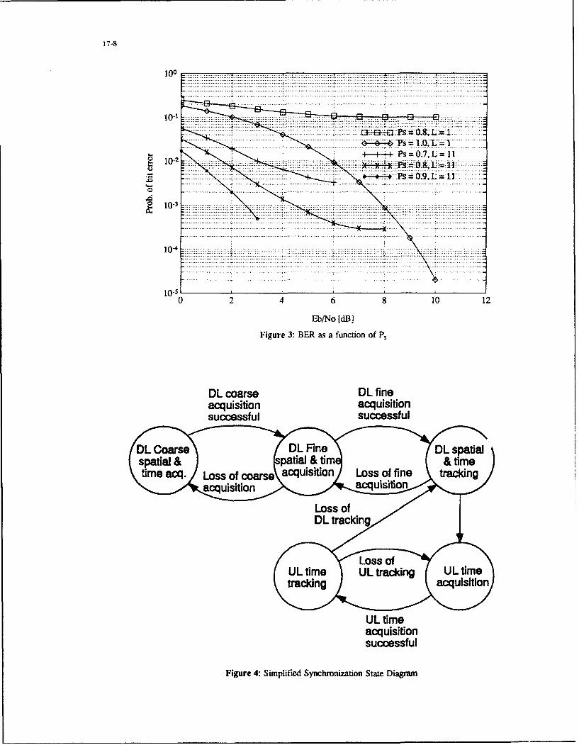
17-8
100 .. .1...j
10-10..2.4.6....0.1............... o .. ...... .... ........... ... ........ ....... ... ........
........Figur 3: B.. ..... a fu.to of.. .- P..... ..-..
....... c o rs ... fine..... ... ............. ...acquisition acquisition.. ------ .......
..uc c....ss f ....l . ............... e ........... ... ..
U s=time =110-2 ................ .acquisition..
Fiur-: Simplif.ed Sync.roizatio S.a.e Diag...........m..
11-9
TACSAT payload. Spatial and time synchronizationalgorithms have been presented and the tradeoffs in theoverall acquisition and synchronization performance havebeen discussed. Based on the tactical requirements of thetheatre of operation, the system designer must judiciouslychoose the parameters of the algorithm to ensure robustoperation while simultaneously minimizing the acquisitiontime.
REFERENCES
1. Pravin, C. J., "Architectural Trends in MilitarySatellite Communications Systems", Proceedings ofthe I.E.E.E. July 1990, pp. 1176-1189.
2. Boudreau, G. B., and Keightley, R. 3., "FASSET: ADevelopment Model for a Canadian EHFMILSATCOM SYSTEM", Canadian Conference onElectrical and Computer Engineering, 1990.
3. McGuffat, B. F., Clarke, K. C., "Waveforms forMedium/High Rate EHF Satellite Communications",The 14th International Communication SatelliteSystems Conference and Exhibit, March 22-24, 1992,Washington. pp. 53.
4. Barton, D. K., Modem Radar Analysis, Artech House1988.
5. Correspondence with A. Malarky of Corn Dev Ltd,Canada
ACKNOWLEDGEMENTS
I would like to acknowledge the help of Mr. R. Keightleyand Mr. W. Seed of the Defence Research EstablishmentOttawa for reviewing this paper and providing suggestionsfor its improvement.

18-1
Terrain & Coverage Prediction Analyses for Non-Geostationary Orbit EHF SatelliteCommunications
Dr. M. Jamil AhmedMPR Teltech Ltd.
8999 Nelson Way, Burnaby, B.C., Canada V5A 4B5
I SUMMARY For tactial reasons, there is a need for communication
This paper examines communication, coverage from five that is available continuously, is secure, has lownon-geostationary satellite orbits. These orbits are probability of intercept, has nuclear survivability, iscircular inclined synchronous, GPS, Molniya 12 and 24 immune to EMP, has anti-jam features, and is reliaole.hour, and Tundra orbit. It also shows the increase in Reliability is determined by system availability (99.99%propagation loss due to irregular terrain and the foliage etc.) and is defined by the system specifications.lossatmm waves, aswcll asthecombined effectof terrain Although atmospheric a.bsorption loss, effect of rain.and foliage on satellite view duration. It concludes that nuclear event, jamming, etc. are included in the "fade"coverage calculations for EHF satcom earth terminals margin, the effects of terrain and vegetation are usuallyneed to take into account terrain and foliage losses, ignored. Inclusion of terrain, obstruction and vegetation
losses will make the system specifications more complete,2 LIST OF SYMBOLS so these losses are examined in this paper.
m degree 4 NON-GEOSTATIONARY ORBITS* minute
AMSL above mean sea level the TACSATS may use polar orbits, inclined circularCIS circular inclined synchrcnous orbits (e.g. circular inclinod synchronous), and inclinedft feet elliptical orbit (e.g. Molniya and Tundra). The elevationGPS global positioning system angle and its variation is determined by orbit and locationkft kilo-feet (1000 ft = 304.8 m) of the earth terminal. 'The elevation and azimuth and itskm kilometre variation with time for the above orbits are presented fornii mile (5280 ft = 1609.34 m) Seal Rock, Washington, UA.Moll2 Molniya 12 hour orbitMo124 Molniya 24 hour orbit 4.1 OrbitsTundr Tundra orbit The five non-geostationary orbits considered bore areWA Washington State, USA listed below:
3 INTRODUCTION * Circular Inclined Syncnronous (CIS)
Geostationary satellites are expensive, afford poor * Global Positioning System (GPS)visibility and degraded performance in the northern zones * Molniya 12 flour (Moll2)and may be not have coverage over a specific theater.Lightweight satellites tactical satellites (TACSATS) in * Molniya 24 Hour (Mol24)non-geostationary orbits for use over a specific theater are * Tundra (Tundr)an alternative.
To determine the size, shape, orientation relative to earthSatellite "footprint" estimation invariably ignores the of an inclined orbit, and the position of a satellite in itseffect of terrain on coverage and communications1 '"-` " orbit. 6 orbital parameters are required. For the five orbitsThis is justifiable when the earth terminal is in a barren listed above these 6 paramet,ýrs are given in Table 1.flat terrain, and the satellite elevation angle is high.However, there may be considerable effect of the 4.2 Elevation Variationsurrounding irregular terrain (mountains), in particular Variation of elevation over a 24 hour neriod of thewnen the satellite elevation angle is small, on satellites in different orbits as viewed from Seal Rockcommunications with a manpack, a shiphorne or a Washington State. USA are shown in Fig. 1. The Molniytransportable terminal. This paper will examine the effect Washon State, US a n inrFig e olniy
24 hour orbit rises to an impressive elevauion ofof terrain and foliage on communications coverage of approximately 89'. Thc maximum elevation angle is 36'earth terminals with non-geostationary satellites.

18-2
TABLE 1ORBITAL PARAMETERS
Parameters Values for Values for Values for Values for Values forCircular GPS-012 Orbit Molniya 12 Molniya 24 Tundra OrbitInclined Orbit Orbit
SynchronousOrbit
Catalog Number cis gps-012 mo~l12 mol24 tundrEpoch Time 78/06/20 89/02/25 78/06/20 78/06/20 78/06/20
21:36:00 UTC 01:41:49 UTC 21:36:00 UTC 21:36:00 UTC 21:36:00 UTCElement Set 1 2 3 4 5Inclination 40.00 55.12940 63.4* 63.40 63.40RA ofNode 3450 216.24300 275* 650 200
Eccentricity (e) 0.0 0.0090905 0.73 0.73 0.374Arg of Perigee -9Oo 180.3094' -900 -900 -900
Mean Anomaly 0.00 t79.65270 0.00 0.00 Q0.0
Mean Motion One 2.0 1388764 Two One One(Rev/Day)Decay Rate, 0.Oe+00 1.500e-07 0.Oe+00 0. oe +00 0.Oe+00Drag, (Rev/Dav2)Epoch Rev One 17 One One OneSemi-Major Axis 42164 km 26487.80 km 2656 L';89 km 42164 km 42164 km(a)__________________ _________ ________ _
100
90
8) 0
fl70
S60
S50
MolriivaI2~j
20 A
0 L- 91A;^ý ... brrrrlAI0 1 2 3 4 5 f)6 7 8 9 10 iO II 12 13 14 15 16S 17 ;01 9 20 21 22 23 24
Time (H-ours)
Fig. 1 . Elevation angle variation for different orbits.

Fig. 2. The Tundra orbit has an eccentricity of 0.374and inclination of 63.4 degrees.
90
900
O(O hrs 15303Ohrs
30
2345 hrS 3
0830 hrs 2245 hrs- 20304 hrs92700 .....
1800 -'0Azimuth
Fig. 3. Azimuth and elevation variation for the Molniya 12 orbit.

18-4
for Molniya 12 hour orbit. 33' for the Tundra orbit, 39" 90 azimuth to East, etc.). Radial terrain data centered atfor the GPS orbit, and 12" for CIS orbit. Of the five orbits Seal Rock, WA for 0", 15%, 30', ..., 345" azimuths everyMolniya24 and Tundra are particularly attractive because 0.1 mi was extracted from a 3 arc-second data base.elevation angle is > -30 for 12 hours. From Fig. 3, it can be seen that the azimuths 305'±15'
The Molniya and Tundra orbits are known for their high and 50'±_15* are relevant for the Molniya 12 hour orbit.
degreeof eccentricity0.73 and0.374 respectively, and an Terrain elevation variations 'ft. AMSL) along 300' andinclination (63.4"). Theirkeybenefitsarecoverageofthe 315' azimuth radials are shown in Figs. 7 and 8northern latitudes and a prolonged hang-time at the respectively. From these rodials, assuming barren terrainapogee. A trajectory and a view ofthe earth foran inclined (absence of foliage), the terrain elevation argle is - 10"orbit are presented in Fig. 2. from Seal Rock. WA, Thus. if the satellite elevation angle
is > 10" there is no effect of barren terrain on coverageNot only the elevation variation but also the azimuth duration.
variation needs to be considered for coverage and antenna
pointing purposes. For a unity ranie (assumed), theazimuth and elevation variation for the Moiniya 12 hourorbit are shown in Fig. 3: note that the diagram is not to The effect of barren terrain on coverage is shown in Fig.
scale and it is included to exhibit antenna pointing only. 9 at 30 GHz. A representative satellite elevation of 20'and terrestrial antenna elevation of 1 ft AMSL (e.g. for a
5 EFFECT OF TERRAIN submarine terminal) were assumed. Radial terrain dataas described above was used. Each curve is an equi-ficld
5.1 Selection of Site stL' gth contour: the labels of the contour are relativevalues in dB's; the absolute value is meaningless.
To study the possible impact of terrain on coverage Seal Bullington method was used to compute the obstructionRock was chosen foi analysis •-or the following reasons: loss. The path loss is determined by the degree to which
* It is representative of the West Coast of North obstructions penetrate the Fresnel zone. Effect of theAmerica and Northern Europe mountains (Olympic Peninsular) to the north-west of Seal
* The site has water, flat ter'ain, and mountainous Rock on propagation and coverage is evident from Fig. 9.
terrain (Olympic Peninsular) in its vicinity Fig. 10 is similar to Fig. 9, except that the antenna height
Terrain dt(ahas been increased by 60 ft. A comparison of -120 and-114 dB signal contours in Figs. 9 and 10 respectively
The coordinates of Seal Rock, WA are 47':43' N and shows that signal level at given distance increased by122":53' W. A map of the area in the proximity of Seal approximately 6 dB with the increase in antenna height.Rock, WA is shown in Fig. 4, and a two-dimensional As expected there is no relief in propagation loss in thetopographic plot with contours is shown in Fig. 5. north westerly direction.
The field computations in Figs. 9 and 10 do not includethe effects of multipath or foliage. The signal probability
A 3-dimensional plot of the area (17x20 mi2) shown in distribution will depend on the earth terminalFig. 5 presented in Fig. 6. The north-west view shows surroundings. Indeed it is conjectured that as the satelliteconstant - elevation above mean sea level (AMSL) begins to come into view and rises the signal statisticscontours. (Note that the vertical scale is in feet, and the will change from log-normal shadowing to Rayleigh tohorizontal scales are in miles.) From topological plots of Rician probability distributions.Figs. 5 and 6 it can be seen that there is water with a fewislands to east of the site, but land and steeply rising To summarize, the distant irregular barren terrain even
mountains to the west. The highest mountains lie to the when it is steep has an elevation of 10" only and does not
northwest of Seal Rock, WA some of these are over 6000 reduce the satellite angulai (elevation) view. The
ft high. irregular terrain however introduces an obstruction lossas shown in Figs. 9 and 10. More important are the terrain
5.3 Terrain Radials and foliage characteristics in the immediate vicinity ofthe terrestrial antenna, effects of these are considered in
For the purposes of propagation analysis it is more following sections.appropriate to examine the terrain data for the relevantazimuths. (Note 0"or 360" azimuth corresponds to North,
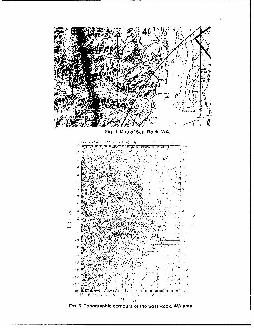
'~ ~ 48.
A81
Fig. 4. Map of Seal Rock, WA.
13
000
'12
-13 0
-9 - ( 6 - 2 0 1
Fig. 5. Topographic contours of the Seal Rock, WA area.

18-6
C)
0
r7 7 Tf/ loe
9909 646c 08
7 49 -,-U

t8-7
6
5
,5,-
2
00 5 10 15 20 25 30
Distance from Seal Rock. WA mriles)
ýe. rrtr, e Iev,--tJoi Ifl 1 2.rnt

"NI I .
F /4
o .00i 11, Al_
--00
ý2.50
Fig. 9 0. Equi-field strength contours; antenna 11 AMSL (..sbmrn)

6 EFFECT OF FOLIAGE Incidentally, the requirement to set up the terminal in aclear area could compromise covert operation under battle
6.1 Foliage Penetration Loss conditions.
There is a paucity of data on propagation loss throughfoliage at millimeter waves. Some information is 6.4 Comments
availablel. 7-10. In general the propagation loss through To recapitulate:foliage increases with frequency' reaching formidablevoliae ia se with G ofr-5 uAttenrachiongduet formidable * In barren environment the useable elevation angle isvalue at 30 GHz of'-5 dB/m. Attenuation due to foliage unaffectedl
is given by':* Distant mountainous terrain does not significantly
a = k f0.75 dB/mn reduce the useable duration of the satellite
where, k is in the 0.25-0.50 range * Presence of vegetation, trees specifically and
fis the frequency in GHz particularly in the vicinity of the terrestrial terminal,reduce the useable duration of the satellite
* Tree covered mountainous terrain exacerbates the
The propagation loss due to foliage depends on the height effect of trees by reducing the useable duration ofof foliage and its distance from the terrestrial antenna as the satellitethese factors determine the path length through thefoliage, which in turn determines the minimum useable * Manpack, transportable and land-mobile terminals
elevation angle of the satellite orbit. The foliage loss are affected by terrain and trees, but the airborne
produces a loss (depression) in the useable elevation terminals and shipborne terminals at open sea z znot
angle. A plot of loss in useable elevation angle vs.foliage affected
attenuation that can be tolerated is shown in Fig. 11 with * In the presence of trees the fading might change fromfoliage height as parameter at 30 GHz. log-normal shadowing to Rayleigh to Rician as the
From Fig. 11, itcan beseen thateven with avery generous moving satellite comes into view and rises
margin of 10 dB for foliage loss only -2 m of propagation * Effect of foliage of different kinds and heights needspath length through foliage car be tolerated, furthermore to be studieda =2" depression in view angle below the tree tops issufficient to consume the margin! That is, reliable 7 SUMMARY & CONCLUSIONSpropagation at mm waves can be achieved only when the * Elevation angles for satellites in 5 different orbits atsatellite is visible above the tree tops. Seal Rock, WA have been examined. Expectedly
the visibility of the satellites in the 5 orbits is notidentical. CIS and GPS elevations angles are low
The combined effect of foliage and irregular terrain can and the satellites are available for shorter duration.be substantial; particularly if the foliage is tall and the Molniya 24 has high elevation and it is visible for aterrain rises sharply in the vicinity of the terrestrial substantial part of the day.terminal. Near the west coast of Canada and USA thefoliage L.onsists of coniferous trees =100 ft tall, and the Terrain and coverage prediction analysis has been
terrain is mountainous, done by extracting terrain from a 3 arc-sec data baseand using the Bullington method for computing the
The elevation view angles of 60 ft high foliage at 30 ft. field. Effect of terrain on propagation loss as well45 ft, 60 ft, 75 ft and 90 ft distances from the terrestrial as the effect of raising (/lowering) the antennaterminal are 63'. 53%, 45%, 39' and 34' respectively on a elevation has been shown.flat terrain. However, if the foliage is on terrain with 5'grade, the view angles are 68%. 58' 50% 44' and 39 at 'There is a paucity of propagation loss data in general
distances of 30 ft, 45 ft, 60 ft, 75 ft and 90 ft respectively, and through foliage in particular at mm waves.Measurements need to be made to determine the
The combined effect can be to limit the unobstructed probability distribution of the signals. Knowledgesatellite useable view to elevation angles of>45"! This of the statistics of the signal will aid in establishingsuggests that satellite orbits that provide high elevation realistic fade margin that is neither onerous nor tooangle be used, the terminal be used only when the satellite low.elevation angle is high, and the terrestrial terminal be setup far far away from foliage i.e. in a clear area.

co
N k ý U)
ae CD .-
LL ca
LL L0 L
C.a)
a) .0)
a) aD (n)
'0U \D
0 CA 0
C.)2
11) ( D
I~ 0 0 .. U.
tO~ ~~~ 00A 001
CV, CMl CY
(8p) e~!ilodj a_ nC] uo!ileueflV T _

* Much work has been done to dete-'mine theeffect o [ 191'i. Robert D, Dyer, F.B.. and Currie, NC..
rain on EHFpropagation, but the effect o terrain and 11-15 October. 1976, "Backscattcr from Groundfoliage togetherhas not been studied. There is a need Vegetation at Frequencies Betwcen 10 and i14)to augment the traditional 'footprint" estimauon GHz," in AP-S Internatonal Swmpp.fium. IFEE,with propagation prediction using topographic and URSI), AP-S Session 3, pp. 91-96.foliage data t101 Hayes. Robert D.. 9-11 October. 1979, '95 GHz
Pulsed Radar Returns." in EASCOV `79. IEEE7.1 Impact on Earth Terminals and Satellites Electronics& AerospaceSvsremsConference. Part
The earth terminals will have GPS or some other 1I. pp. 353-356.subsystem to determine the position. which can becommunicated to the satellite. The incorporation of 3 1111 Hirsch ler-Marchand, P. R.. Bcrglund. C. D., and
arc-second terrain data base along with data on Stevens, M. L., 1980, "System design and
vegetation and man-made structures in the satellites % ill techr-t.ogy dcvciopment Icr an FHF beam-h-opped
aid in determining a suitable time-window for satellite downlink,'" NC. pp. 17 5.1 - 17.5.7.
communications. At the very least consideration of [121 McElroy, D.R. andEaves, R, E_,Apnl21-24, l9s().terrain and vegetation losses in link budget (EIRP, data "EHF systems for mobile users.' AIAA 8'thrate, etc.) will make the system design more complete and Commurucatons Satelite Sw.teas Conference.thus improve reliability of TACSATS. AIAA.80-0561 -CP. pp. 509-5 15.8 REFERENCES I131 Matheson K L. Auszusi, Stellite acuca
1I1 Ahmed, M. J.. Nov.. 1988. "Secure satellite communicatons a[ high altitudes," Pr~weeanis c'7the ,'9,4 SmPfo.lum ,)n `hlitar'v Spacecommunications,' Canadian Cognferencen iiCmmunications and Operations. Colorado: U SAFElectrical and Compwter Engineerinm., Vancouvcr.
B.C. Academy.
[2] Ahmed, M. J., 16-19 October. 198(), "1 actical EHF f1-4 Niessc ti, C. W., 1983, ".llsatco5 trends," ICC.
Satellite Communications for NATO Employing
Non-Geostationary Orbits." in "'actacaic. 151 Ruddy. ., ,M., June. 1981. "A novelApplications of Space Systems". AGARD CP 401. non-gcostationary satellite communicationsPaper 39. system." Confert'nce Record Internationa;
3] AhmedM. J.. June. 1989,"EHFSATCOM System Conference on Communications, Colorado, pp.
Design," Canadian Satellite User Conference 1989. 54.31-5.3.4.
Ottawa, Ontario. [161 Turner. A.E. and Price, K. MN. June 1988. The
[4] Allan, R. R., November. 1969, "The operation of- potential in non-geosynchronous orbit," Satellite
Molniya communications satelites," 'Technicui Communlcations. p. 27-31.
Report 69266. U.K.: Royal Aircraft Establishment. 9 ACKNOWLEDGEMENTS
151 Bhartia, P. and Bahl, I1.. 198.4, Millimeter Wave The author would like to proffer thanks to MPR TeltechEng:ieering and Applications. New York, John and Drs. Alan Winter and Norman Toms for support toWiley & Sons, (ISBN 0-471-87083-8), pp 153-186. present the work, is grateful to Mr. Dennis Ro~enwuer for
[6] Collins, J., Deslauriers, E., Matheson, L., and Ohrt. providing the computer programs for orbit computations.J., 1983, "Tactical military communications by and is indebted to Mr. Donald R. Heywood forcontinuous
ratellite relay at high altitudes," AGARD-CP-344 support and numerous helpful suggestions.
[71 Currie, N.C., Dyer, F.B., and Martin, E.E., 11-15October, 1976, "Millimeter Foliage PenetrationMeasurements," in AP-S International Symposium,(IEEE & URSI), AP-S Session 18, pp. 575-579,
18] Cummings, W. C., Jain, P. C., and Richardi, L. J.."Fundamental performance characteristics thatinfluence EHF MILSATCOM systems," IEEETrans. Comm., vol. COM-27, No. 10, pp. 1423 -1435.

19-1
lAUNCH VEHICLES FOR LIGHTWEIGHT TACSAT DEPI)YMENT
Chester L. Whitehair and Malcolm G. WolfeThe Aerospace Corporation
PO. B1ox 92957
IA)s Angeles. California. USA IXXNW-2957
I. SUMMARY National launch System (NLS) however. planning I,[he need for tacsats is discussed and typical tacsat mission liunch tacsals as single payloads on small launchers (tLxOd,requirements are identified. A spectrum of potential tacsat rclchatable. or mobile) is not ncccssarily the most cost-.effec-launch systems is identified and characterized, including Tive optionboth US and non-US systems. and ranging from existingoperational vehicles to very advanced vehicles that - ill not Instead of separately designing and developing the orhitingbecome available until weil into the next century the six vehicle system, which is later inigrited with a separatelybasic launch system design drivers, performance, cost. opcr- designed and developed spae maunch sstcm. the taosatability, launch responsiveness, launch flexibility, and surviv- option opcns up torconsideration the concurrent design andability are discussed as they relate to• tacsat launch dcvciipment t a singie system or which the irbiting vehiclerequirements. I'he launch systems that are described are .ind the L;iunch vehicle are merciv m,xiut,r elements [ hecategorized into: (a)mainlne launchsystems. (b)small fixedi concept of using the launch venic:c upper svaie as a space-relocatable/mobile launch systems, (c) ballistic mis- Craft bus is not new and was used successiullv hb !Ai A inedinsile-derived launch systems, and (d) far-termo launch systems. their Agcna program I here o come evidence tor believingIhe impact of the US/CIS Strategic Arms Reduction ILtiKs nat such weapon systems ais Nike mnd the air-cruise missiles(ST.'\RI) agreements on the availability (if surplus ballistic tre inherently more operable ,han onv- nnonal spacemissiles is discussed. [rhe availability and utility of a wide :aunch systcms. If the design phillosophyddescribed ah-ove (toselection of global launch sites are also examined. It is con- consider the orhiting subsystem and the launch subsystem aseluded that the general tacsat mission is a viable concept. and Clements of a single. integrated system , is adopted. it may bepossibly satisfies a very critical future need. It is demon- possihle to improve the operahility and iower the cost of sat-strated that the tac_,at launch services needs into the foresee- sfying lhe s;ant tactical mission requirements by the histon-able future can be supported by US current and planned cally conventional parallel system development aporoach Itlaunch systems launched from existing US launch sites. is coniectured. for instance, th t a vanetvof missions couldHowever. numerous other options are available and slhould lie satisfied by selecting and i.ssemhling different systemsbe investigated by the tacsat system dcsigner/planner for from a limited inventory of standardized (modular),orbitingviability and cost effectiveness, vehicle and launch vchicle subsystem elements.
2. INTRODUCTION ,\lso included as candidate launchers are the strategic ballis-The North Atlantic Treaty Organization (NAT(-O) alliance tic missiles that will be retired its a result of the emergingmust respond to the change from a fairly stable geopolitical SIAR F treaty agreements Special limitations on the con-environment, with a well-defined adversary, to a very verson of hallistic missiles tospacc launchers applyand need
dynamic envronment where the adversary and the theateriof it be consideredoperations could change several times during the lifetime otsome of the culrrent tactical satellites and where conflict It is evident that the tatesat concept intr(i•uccs t number otcould arise in mofe than one theater at once. The evolving complex new issues that need to be addressed and that mustworld situation also suggests that there will be a need for less be placed in the context of a total cost--effective system solu-emphasis on new strategic systems and more emphasis on tion to a dynamically evolving threat. However. this papernew tactical systems. It has be,.-n proposed that what have does not propose to resolve these broader issues but isbeen called "fightsats" or "cheapsats." but what are termed intended todescribe the launch vehicle options for launching"tacsats" in this paper, could be candidates for satisfying new lightweight tactical satellites to satisfy a variety of potentialevolving tactical mission requirements. Such satellites would missions. Fhe potential missions and the general character-place new requirements on space launch services, which his- istics of tacisats that might satisfy these missions are deln-torically have evolved in response to requirements for larger eated. The important factors in the identification of candi-and larger payloads on orbit, whether their mission is tactical date launch sysvems for these missions. i e.. weight. dimen-orstrategic. I Use of the current (IS mainline launch vehicles. sions, orbits and constellation architecture of the satellites:for instance. would entail launching tac-satseithcr as multiple and performance. cost. operability, launch responsiveness.payloads, or as auxiliary (piggyback) payloads on a flight launch flexibility, and survivability of the launch system, arewhose primary payload is a conventional large satellite. In characterized. Requirements for launch responsiveness andcurrent practice in the US. the latteroption would not gener- launch flexibility are not well defined, but a spectrum ofally he available on D)epartment of DIefense (DOI)) flights options is discussedsince DOD payloads aie normally designed to utilize the fullpayload capability of the launch vehicle. Conventional ['he launch systems are grouped into (a) mainline launchscheduled flights w'ould have to be re-planned to fly systems; (b) small fixed, relccatable, and mobile systems.off-loaded in order to permit tacsat payloads to be added if a (c) ballistic missile-derived systems, and (d) far-term systems.sudden crisis generated an unscheduled need. The establish- The primary focus is on (IS launch vehicles and launch fromment of such a policy could impact the payload requirements the continental I IS, but the capabilities (if other nations'for upgraded Medium launch Vehicles (MI.Vs) (r the new launch services and launch sites are also described. This is

19-2
because it is unlikely that the I S. or even NAlO. will take Ficsat weights cant range tromn less than it) lb (23 kg). in themilitary action that would involve unilateral full-scale use of case of the D~efense Sciences International IN-itrosat. to thethe taesat concept as discussed herein. Although resisting 150) lb (68 kg) Macsats which wt~re used with success by USlocal despots needs single-minded leadership. and only indi- Marine units during the Pecrsian Gulf War, to 1.500 lbvidual governments can trul ' provide that, the US and (OM4) kg) Iridiumn-like satellites%, i arbitrary definition ofaNATVO miusi coordinate otfensive action with internatioinal tacsat is that it should weigh less thain 2,2W~l I (1.000 kg) andorganizations such as the European Cormmunty (EC). the be launched for less than $20,M. alathough some commercialU~nitedf Nations jUN). thle Western European Union iightsats have already been launched for well under SIM). AIWELII), the Conference on Security and Coo~peration in- hettergotil might be aweightof less than 1.5(X) lb(Oh1 kg)andEuorop tCSCE). and %ith other nations, including the sev- a launch cost of$ I 5Meral ex-Soviet Blofc nations that are indicating an interest injoining N~klH) or the EC for mutual military and economic iable I showsit potential set ot iacsat laiunclh requirements.secu rity. [be gliibal market for. and utility of. tacsats must [he missions include at broad range of capabilities thata fieldalso, be examined in) the light oft the tpnSkies' treaty commander needs, including communications, weather.signed on the 25 March 1992. in which 25 countries. includ- land and ocean surveillaince. theater surveillance, and missileingatll the 10 NA:l?) countries. J East European cx-meinbers. warning. In most cases. the- iacsatsi wiiuld serve to augmentof the Wairsaw Pact, and Russia. U kraine. 13clonissia, tand the larger conventional sateilucs, by providing the field com-Georgia agreed to permit airborne kvertlighlt of their manders with dedicated assets. aind may be used to reconsti-ierritorv. lute unexpectedly failed satellites on at temporary basis.
Treatv monitoring is included. although this may be more a3. lAUNCII SYSTEM SELECTION CRITERIA support t -unction to. for instance, the I nited Nations Secu-
rity Council than the battlefield commander.Liesats can either be- launched on demand, launched onschedule ats primary payloaids, or launched as payloads of Table 1 Potential Tacsat Launch Recluirementso~ppoxrtunity (auxilia~ry payloadis flown piggyback on rcizularlv,ched.iei fllgbts) [he iaý%at mission raises thec Nsu, tiis '.'. -
tving laiunch system design requirements trat ntav poissibly-have not been satisfied oremphaISII'Cd inl the rA2t. IrAdition- :','il launch and missile svstenti design drivers cart he ri uilvh "'"".v '
divided intto six cilegiirics: (ti) performance. (b) cost. .,,, ,*-
(c) operability. (dl launch responsiveness. lce L~iincn tliesh I-Iltv. tind (f) survivabtlity. [ he members ot the three ni~iqor.,-.tam'2C li f otMainline US5 expendable liiiunvn vhicles, Atlas .... :
I )lta, and litan, are examples ot peiriorm aince-driven ,,~
designs. Phe t.1 !S'pact; Shuttle wkas piannc6 to he ai ..Lcost-tIriven system hut, in common with all launch systemsdeveloped up ito the present, did not achieve its Poaf 4l low- ;~:cost ticcess to spaice. I hie I N Advanced l aunch Svstenc. .
(.AI..S). now replaced by the INI S. v~as conceived as biihoth tin iipertiilatv.r Invert and at cost-drtven svstent. I hesolid propellant ballistic missiles, such ats the US MiinuteraniiIll (MIM-Ill). are exaimples of launch rcspo~nsivcness-drivensvstems and therefore any space launch derivativeý (if btillts-lic missiles will inherit this design charaicteristic. Dhe It is seeni t inom I'lihI I that thc, orhits 1,Or the various missionsair-mobile systems. such ats the U S Pegasus and the proposed ,ill into two genertil categories. (a) geosvncbronous (GEO)
ornmonwralth of Independent States (CIS) Spatce Ctipper. i)r bighty clliptic for continuous uCrtiN~e mtissions: andrepresent systems that provide the launch flexibility to select ;h) low it-tb orbit (LEO) suin-svnchrono'us for all inclina-ýtbeneticial locatiton for it specific mission and an al-aziitiuth itons (Ito cover any plotential targe~t area) for Earth sur-
launech capability. %eilltincc m-issions i ligh attitude satel clites would probably bestored on orbit prior ito hostilities. An aittempt is made to
Survivability is an additional design driver that has histori- quantify latunch respo~nsiveness requirements. Satelliteetilly been of importance to weapon delivery systems. -%t %kcights are based on very preliminary tacsat designs, andpresent. survivability does not appear to be important to file- should in no way be ecinsidered firm requirements.sat launch system-,. but this factorcould become more imrpor-ttint in the future as more developing nations gain access to 4.2 Constellationssophisticated offensive weapions. Jiesat constellations can range from single satellites to com-
plex multiple satellite global constetllitions, such ais an4. REQUIREMENTS Iridium-like global communications constellation that
inicludes 77 satellites in 7orbit~tlplaines. Since there could be4.1 Mlissions scenariros where multiple tacsatts need to be launched at one[ he overall tacsat mission is characterized by the tneed to time, potential launch options cannot necessanly be con-;iugment capital spacee assets during tines of crisis. the need fined to small launch systcms. Opportunities for payloadto surge at thecoutbreak if a major conflict. aind the need to manifesting must be examined in order tointprove cost effec-reconstitute space systems that haive been daimaged or tiveness. It is conceivable, for instance, for a whole plane ofdestroyed. llRsats satisfy ia militairy need to provide -space I I Iridium-like Itiestits to be deployed on ti single mainlinesystems that are dedicaited to support itacticail commatnders liunch vehicle.without inflicting ai heavy (igisticatnd administraitive respon-sibility. Idealtly. the battle commanders need the operational 4.3 Payload Manifestingcontrol to task saitellites ats their own assets to ensure direct Fo r constellations with a large number of snmall satellites in aand timely access to real-time daita and information from large inumber of orbital plaines, manifesting on mainlinespace. U se of the space systems should be tin intrinsic part of launch vehicles is an tsttractive option. At low-to-mid inclina-routine peacetime military training exercises and not lions, the most effective means of distribution is ito use orbitalbrought into play only to respo~nd to tin actual war-fighting regression. Spacecraft are launched into a park orbit sepa-emereeny. rated itl ifoude from the mission orbit Earth obtatencss

P4-3.
causes it naturalI drift. or regression. of the orb its. and t he rate .5.1 C'urrent and Ntar- Fermof drift is a fu nction of the altitude (and inclinationt of the 5. 1.1 1 iiid fuStae U'Sorbit. Thlus the differential regression rates biet~cen the twAo Ihle current I iS mainline la~inch sv-steni families include thecorbits permit a phasing of the orhits to take place okcr time. Alm Della. and Titan lan.''ein.s 1w "as~,i Della. anuAt the appropriate time. wsith planes aligned. a spacecraft Ititan 11 are medium launch %Vhil2t-!. -.oin payload capahifi-destined for a certain ring performs an inter-orbit transfer tiso bewe 0,WOM and MAWfl lb (2.72S and 9.lY)t kg) tointo its respective mission orbit Regrsionm rates, however. L EO, I Ieavicr lift capability is provided by the ('nimmrcialire reduced at high inclination and, in fact. arc /zero for Titan IIl and the Titan IV'vwhich can lift'close to 48AM~ lbpolar orbits. Thlus, for high inclination constellations, this (2'88kg t ro.LOaipproach is not practical.kg
Ibhis group of launch vehicle,, is the most viabhle for the highA\ second strategy is to launch the space~craft into the samec energy tatcsat missions, riot only because of pay load ca pa-altitude as the mission orbit, but at a lower inclination, thus oility, hui because the suggested store-on-orbit 'stratcgy forestablishing a iclative regression rtite based oin the differen- ihe (it:() satellites is consistent with their current lowtiat inclination. Ibe planre-change maneuver to inject the response times Thle Titan 11 can currently be f14or1 onlys~pacecraft into the mission orbit is a high energy maneuver, from the west coast launch site at vandeniberg Air Force Ilasehowever, and the energy required increases rapidly its the iVAFIIl) in ('alifornrit ! he lDclta If can deliver 2. IME lbmagnitude of the planec change increases. Thle plane-change: {91i1kvl ,nd the Atlas 11. 3 IM lb (TIt) ~kg) to (.ijE( Furimaneuver implies the use of propellant. which ret. ices the *LIEX) lb (45-5 kg) satellite,itthis translates in to aboiut 25 M piernumber of satellites that can be manifested oin a single payload launched twom at a time on D~elta or three at a time onlaunch. A balance between plane change and ateeptable \tlas. %knife for I.5W lb W4~2 k 'v) satellites. these numbersregression time must be established to make effective ue oit become aibout $50 Mi for a single sitellite on Dlcltaand $44) \ithe launch system. performance. -:tell for two satellites oin Atlas I he viabilitv (it !:unehirnc
multiple satellites ito OE( ) ould hake to be astsessed hs' the.4.4 Launch Responsiveness 'er-s. outiit vkould wpicpar to be ;i reaso nable approach sinceA further consideration is thle launch systenm respi Insises .:icrc ire three t l( rD )inssio ns identified- and. in ziny (-uoe.I1 r tacsat missions. there is arn imatplicaition of hei a. 11 is--jnt 1,ircs tCan he dcoi~ioed it 'umctwrnt excess too "rclv of the satellite system,. both on the ground aind on1Ce it is in .i ciiteisýi- :;c benetit o1 conitroihins, siilcite weicehi.
o)rbit. Intdiint %ucnn h is aelierpdy hr iihom ini mpromirsing nivsion c~tihilitv. is apparent.is the issue oft lau nch repetition rate requiremeCt)s (the need
torelioad the wsiml Tb'hs IMIV be Sovd t ait SmilO t I cur am ii a r lies ithe pa. loaid cipý61ihiitics of the currentstolrage. test andL Ia iineb pad ftirt iitets. or raipitd reeveim Of miSTT-jamUn Wd l~iri~c nmainine espndahle laiuncn kehiti'Csthe pad. or most prohihlv at conihinatmon of both. In cserv io %iiriou iits iol interest aind several oither charactcrisitio..case, the more rcsponsivitv required. the highecr the -uch ;is payloadl accom nin-lation. rt iabilitv, an cost pI
non-recurring cost for facilities and equipment and the 1ihi I iunch rite capaicity circa 1995 is also shiiwn.higbcr recurring cos.,t fir matnpot)er and minteincniice. T'rad __________________________studies need to he rnatde \%hen launich rcsponsisemiissrequirements are bt-wter defined.
IBal list ic missile-dc rivatives ioffe r the I ~ossihijtN ( it 1f iaunchingin at matter of seconds if they aire maintained oin ailert status awith the satellite in the samei state oftreadiness. Ihisdtoes nut -
seem to he a necessany requirement for tactical situations, atleast in the near-term, since there is it low priibabilitv of the c~4ASSS1rapi6 couniterforce attack assumed in the ease of strateee ' j!K owballistic missiles. A more reatsonable tipproach would he to?,t.'lO - .'4'
store the vehicles under eindiimons that would allow- theta to ~I~ ~ .
hex- hrought into a state of launch readiness in ii maitter (it 04~ -.
days; t hey coulId be lau nched on dieminand in a mna tter oif ho u rss ~ a.- , J.
if desired- 4YLOAo ACZQýiORI ,4'1
-1 '1;AC
From the ultimate tesponsivitv oit the ballistic missile- . MI I 1-:m. LL
derivatives, the next Most respo~nsive systems are the small,~m 0 1 ,
fixed, rclocatable. or mobile launch systems. It is anticipated - k,that t hese syste ms coulId he launrched m na mnatter of daysw-it h- 1' 1out at huge investment. Finally, thie current medium andlarge launch vehicles have long callup times because they arenot designed for high responsis'ity hr recycle times. Ihere-fomre it would take a large investmenit in launch site facilities iti Frgure 1 Current US Ma 'line Launch Systemsbsring their rcsponsivity intii thle )nc iii two week range. 5111131 iil ft'oI~
lIme DeltaI to fani itof~ vehicles %vits ic rived f riom the Ilb 'r5. MAINLINE LQINCII1 SYSTESMS Intermediate Range Ballistic Mfissile (1RPM) by addingscv-There are presently four naiuimn-SttitcS that offer routine eralsnall Solid Rocket Motors (SR MsI and the lbelta secondglobal mainline space launch services tile U nited States, stage. IDelt,is. are used to launch payloads into (lEG andFu rope. the C ommonweailth oif IndepiendentitStates, and] the L EO frm Eastern lest Rin;mge t~l:RI liunch complexes['eoples Republic( China. Jcbnicailly. Japan also has a I C-I7A and I E- 1713. and to polar orbit from the Westernmainline launch system. the li-I. Hlowever. this vehicle is lecst Range (W1R),spaee launch comiiplex SIC(-2 1he capa-currently being ph~ased iiut in favor oif the 11-2 and made it,; hilitmes iiave grown through a series ofupgrades the primeClastflignt in February. 192 When the 11-2 becomes opera- contractor for the Delta family of vehicles is Mcl~onneciltional. five nation-stlaes will he able to provitde mainline Douglas. H untington Rleach. California.launch services. H oweve r. dIifficultlies being experiencedwith the 1,F-7 cryogenic first-stage enigine could delay the Theli Delta It was selected ats the Air Force Medium Launchpredimcted 1991 initil lauIIalnch capability ditict. Vehleci, f MI lV-I) aind is current ly us ed for ltu nchi n g thle

19-4
N:AVSTAR Global Positionng Satellite (GPS). Space trom 9W lb to2,971f lb (450 kg to 1350 kg) to 1. ) at.25 _5 degDefense Initiative Organization (SDIO) experimental pay- on launches of primary payloads]mds. NASA scientific payloads, and commercial payloads.The initial version (Delta 6925) first flew in February. 1989. 5.1.1.3 l'itanfamiy ofvehrclesfollowed by an upgraded version (Delta 7925) in November. The Titan family of vehicles is a series ot Air [orrcc vehicles1990. Delta 7920 has nine Graphite Epoxy Motor (GEM) that has evolved from the litan I('BM sysecm over the paststrap-ons and supports the heavier weight of current GPS 35 vearsý Three main launch vehicle conhiguranionspresentlysatellites. Atwo-stage version exists tor each Delta IL: )elta exist: Titan 11 Space Launch Vehicle (SIN). Titan III Com-,920. which iscapable of placing8.8(X) lb(4.(XX)kg)into LEO mercial. and Titan IV. with variations oi each All t-.ive v,,iduceast:and D)clta7920.which iscapahleofplacing 11.100hb core stages using liquid propclants. fhe last tIK) use sCg-(5.045 kg) into LEO due east. The main difference between mented SRMs for the initial stage to enhance perlormancethe D)elta 11 vehicles (6920 versus 7920) lies in the use ofCas- Composite-case SRMs (designated SRMIJ )•ill soon replacetor Solid Rocket Motor (SRM) strap-ons (steel cases) versus the steel-cased solids to provide increased performancethe use of GEM strap-ons (graphite epoxy cases) The Delta Additional proposals for increased performance include the792_5 provides performance to transfer orbits and uses a third use: of liquid cryogenic propellant boosters, more and longerstage. r'his third or upper stage is a modified PAM-D. with a SRMs. and more liquid engines with stretched ancLdor largerStar-48B solid motor mounted on a spin table to spin-up diameter core stage tankage [he prime contractor for thethe stage/payload combination bef )re deployment- Incor- litan family of vehicles is Martin Marietta Corporationporation of this third stage provid;.s the capab'itly to deploy .Astronautics iroup, Denver. Colorado.4.010 lb (1,820 kg) of payload into GTO (without the thirdstage. only 2,800 lb (1,270kg) can be deployed into (G0O) An litani 1. The Titan 11 space launch vehicle was conceived byadditional spacecraft kick motor is required for gcosynchro- l)(I) to utilize an existing resource and, at the same time.nous orbits. augment the dwindling Atlas E launch vehicle inventory for
launching smaller payloads it) polar orbit. [he fitan I15.1.1.2 Atlas fazmily ofvehicles %ehiclcs (like the Atlas E vehicles) are lormer ICBIM weapon
' vsiCniS thtli ha•,t. been deco•mmisstioned. re'moved tromThe .\tlas is a former Air Force Intercontinental lalhstic %silos rhith edeomied itned, acetfed fr
Missile (ICBM) weapon system converted for use ais a snace
launch vehicle. The Atlas 1) was man-rated and flew tour 'pace thght [here were originally 55 tit~i ICIMs in inven-successful missions during the Mercury program, including tory, and the Air Force has a continuing program to modif,the first U. S. manned orbital flight by John (ilcnn [hc sys- and launch these vehicles as required. [he initial launch ca-
term concept. now over 30 years% old, has gone through it pahiitv ol the litan II was achieved in September. 1988. The
senesof modernizations and upgrades, which have enhanced ,-itan 1 can place up to 4.2fX) lb 1,91) kg in I.E) polarorbit
Its payload performance capability considerably. [here are Irom space launch complex SIt.-4 (West) at VAFT) Proptos-several Atlas versions. existing and planned, hut common t fls for upgrading Titan Ii ptrtormance include dceveloping a
vall is the use of one anda halfeliqid propellant stages. cmoth ('ape Canaveral capability, long duration circularization,alleis theuseof"ne and "a " halfliqdarc ignted on the ground burns with added pr(opellants..and SRM strap-ons. The addi-"stics igoosie an tsustrinnd tlion of ceght Castor IVs. for example. would launch h.900 lband burn in parallel. After the b(x)ster engines are jetti- (4.045 kg') to LEO polar. Configuration studies inclu le thesorted. the sustainer engine continues burning to orbit [he (4.1)4 kg) to 10 poar sonfgrtion strdie .n tprime contractor for the Atlas family of vehicles is ( cneral iddition ot up to t0 EM solid roket motor strap-ons
l)ynamics Corporation. San D)iego, C'alifornia. ritan It. in its ballistic missile configuration, can be launched
with less than one minute ofwarning since propcilant can beAtlas E. The Atlas E is a 11OI) launch vehicle presently used left for long periods of time without deterioration of the fue!to launch smaller payloads to low polar orbit from space tanks or the propulsion system.launch complex SLC-3 at Vandenberg Air Force Base(VAFB). The vehicles are former Atlas ICBMs that have C ommercial uitan I/[ The ( ommrc Fial in Ill is derivedbeen decommissioned, refurbished, modified, tested. and trom the T-itan 341) with a stretched second stage and a ham-certified for space flight The Atlas Eis primarily used tosup- merhead (largcrditamcter)shroud for dual or dedicated pay-port the DOI) Defense Meteorological Satellite Program loads. The first commercial l'itan Ill was launched in(DMSP)and the National Oceinicand AtmosphericAgency l)ecember. 1!989. and can launch 32.0M) lb t14.5410 kg) into(NOAA)satellites. Itcan place 18001b(880gkg)into lowpolar L.EO. It is compatible with the McDonnell t)ouglasorbit. Only a few vehicles remain in inventory. PAM-t)I[. the Marlin Marietta r'anstagc. and the Orbital
Sciences Corporation Transfer Orbit Stage ([OS) upperAtlas I/. The Atlas If is used for communication satellite stages to provide GTO capability of 4080 lb (1.850kg). 9500 lblaunches such as the [)efense Satellite Communications Sys- (4.320 kg). and I .(X)0 lb (5.(M0 kg), respectively. Perform-tem (I)SCS-ITl). It was selected as the Air Force Medium ance to GEO is approximately 5.500 lb (2,500 kg) using aI.aunch Vehicle II (M1V-Ii) and is designed to perform LEO spacecraft kick motor. Martin Marietta has examined aand (iTO missions. It consists of the booster and a ('entaur number of payload deployment schemes for launching smallupper stage and can place 14.1(X) lb (6.411) kg) into IEO due payloads, both as auxiliary payloads and as multiple primarycast, 5,9(X) lh (2.080 kg) into (0TO. or 3.I(1) lb (141f) kg) into payloads. but these design options have not been exercisedGEO using a kick stage. ritan 1V lhc T )( ))'s Titan IV development w-as begun ;is a
complement to the Space Shuttle, but following the Chal-lhe Atlas contractor is offering four versions of the Atlas: lenger accident, the program was expanded to accommodate
Atlas 1. Atlas 1, Atlas IIA, and Atlas IIAS for launching critical DOll payloads. rhe program A-s further expanledNASA and commercial payloads. I'he Atlas IIA.S is an in- in 1987 as the full impact of the Shuttlh delays and cancelia-proved version of the Atlas IT that has solid strap-ons and in lion of the Shuttle-Centaur program becamc clear.which the Pratt and Whitney Ri,-I1} engine in the Centaurtipper stage is increased in thrust from 16.5(X) lh to 20.800 lb the Titan IV uses either a 7-segment SRM or a 3-segment(7.500kgto9,450kg). TIheAtlas tIASpayload to i(OI willbe SRMI[, It is now capable of delivenng l.10.000lb(4.550 kg) to7.700 lb (3,490 kg). GEO with the current 7-segment SR Ms. When the SMRU I
boosters now under development are available. the Titan IV.Genreral D)ynamics Commercial L.aunch Services has pro- ('entaur will be able to launch 12.700 lb (6.350 kg) to G-Opo)scd carrying sov-callcd "companion' satellites ranging lie litan IV/I IJS is currently operational and is capable ot

delivering 5.2503 lb (2.3%)1 kg) ito (iE( .A itan IV` with no 5.1.4 Acopkes Republit. of ( Ywin i /'Rupper stage is used for launching into polar and high nerilina- Fhe PRC is represented by the I sing March family o(Ition orbits. This configuration can deliver YOMNX lb vechicles China's space launch servics decprids (n at number-(17.700kg) ito LEO due east, or 311MM) lb (14.0t) kg) it) a of interacting organizations. each. of A~hich is responsible for1IM rim (185 kin) polar orbit. Thel itian IV could. in theory, part of the launch servces package I he China (jr-cat Wallfly auxiliary payloads but this is not at very practical option Industry Corporation ((GWIC) is responsible, under thesince its primary payloads normally use full payload capabili- Minisirv of Nstronautic~s. for coordinat ion betweent foreign
tv. customers and the other elements (if the launch servicesorganization. [Ihe launch capabilities oft the I Aing March
55.1.2 E'rp family are sum marized in IFigure c
Europe is represented by the Ariane 4 family. which provides 52 I eeomn n lnea range of payloads from 81MMX) to 2141MM lb (3,63N~) ito .)nDvIpnn n ln9-545 kg) to LEO. There are six versions of .- rtane 4. with a Ibhree nation-states, the IU.nitedl States. Lurope. and Japanmix of liquid and solid propellant strap-on boo~sters. 1[here have clearly laid out plans to cxtend their mainline expend-Lire two subsatellite services, the SPELDA (Structure Por- able launch vehicle fleetteuse Externe rkiur Lancement D~ouble .- riane). D~edicatedSatellite Service (51)5). and the Ariane Structure for .- uxil- 5.2.1 Umted Siates!ary Payloads (ASAP). plus different versions of ihe Medium Launch 14/itcl 3 IMI.I _.. I he I. 'SAir Force plansSPELDIA, payload fairing. In this way, it caters ito a wide ito award at contract during fiscail \,ear 100t3 for the Ml V-3.range of payloads. The vehicles are launched from a launch which wouuld bccome available in 1996 and hats, ats itsprimar\site at Kourou. French Guiana: at launch azimuth range of mission. the launch of GPS IWo-ck [TR 1be MIV-3 is in-104dcgtspo)ssible fro~m349.5to93.Sdeg Fhecostpertlight tended ito bridge-the-gap" until the NI -S is avaitable, andfor a single (iTO launch is between O)iM and S95M. any performance improveCments will be tinanced by pnivate
tindustry [*bis procurement could contlict with the procure-
F ifty satellites have been launched usingz tlte SYLD (Sy. , ninotc laddciii ss-ac oemdei~ntemede Lnceent ~oule :riant o SPE~l)\ (l-il crss ito select one or the other Alihouctn no characteristics,
launch capability, which hats resulted in at satellite dcIv ) the NIl V-ll I are releasanlhi it ttis time. the proicurementmetrt fabo~ut 12 per year. up from 7 i)8 launches per colprvdanpoun tpi t isctnryux-
year previously. [he launch limit for the .\riane 4 is set at . paii epomnIll flights pecr year. which tlo~ r delavs or probletits Natir)cl Lman~ir S.\vNt,,m r.l I lie N I S is using an evolu-Ibhree coimmercial microsatellutes have beet 0o~n using the
ASARand s mny i.,;six SAP ttahmen ponts an ionar% approach for the developmecnt ot a tamily of launchand s mny S si ASP atacmentpoits art vehicles and operational infrastructure sith the capability ito
eaccommodae mutiple ASPsatelltesupe in ahou reere lb for1 place a wkide range of payloaids into orbit at a fraction of cur-each [h enire SAPstrctur ca beresevedfor rent costs. [he operability goals of NI-S are to make space
between $710.IMX) and SSIX).(XX). In order to satisfy custom- liunch activities as rout ine is those oit a long-haul truckingers* demands. it shortened version if SPEED.)A, named SO' )5an(Spelda D~edicated Satellite) is being built by British Aero- copn-space ito accommodate a satellite in the 2.7WM lb (t).IMMI kg!) [li N I -S chicles currenitly serving ats -siints of referenceclass, plus an additional satellite of up to8IM) kg. Ihecapahil- -
ities of the Ariane 4 are summarized tn Figure 2. range from at small, two-stage vehicle capable oif placingapproiimate ly 20.1M) lb MOM 9(kg) into I .1-) (the immediatefocus). to at tinc and oine-half stage vehicle utilizing a Shuttle
rAriancspace. the commercial consortium that operates .- ri- Exrternal link (ET) derived tank section (common core) forane. predicts the minisatellite market (commercial and mdi- mi~xlerate sized payloads lit I F(). md capable of beingtary) to reach 20) per year by 1993, and its aoal is to capture upgraded to a twko and one-h-ilf st-ice %chicle (by adding an50ý oif the market. upper stage) with (iE( cap'ability. ito a ievy lift conligura-
tiiin usunit ASRMs as siran-on boo~stcrs, the common core.
5.1.3 (optirionwealtlz oflindepridezit ,Siates to 'IS and a cargo transter vehicle ( \ or cargo delivery' toIhcaailhiltvoex-Svie Unon aunh sytem isompin- Space Station Freedom (SSF) A nec NI ýSupper stage. used
I'ea,,tlibliyifx-ovc[Jioliuchvscmicop-. with the one and one-half staize vehicle for ClEO missions, isfactdthatthe political changes that arc tatking place and the also being considered for use ats the finail staige of the 20OXM) lbfattaIspace astarnolonger controlled by itsingle au- (900k)(IS3 eil ofurther provide commonality
thority. At least five space agencies (three in Russia) appear Vehicles with increased payload capability, attained via mod-_to be emerging and at least three members of the Common- uWar growth to meet heavy lift requirements up to 124,0(X) lbwealth (Russia. Kazakhstan. and Ukrain) are laying clainto ( 56,30~) kg), are also under study. Payloaid estimates for thethe potential benefits of marketing space technology to the various members of the NU.S -family meet bioth NA.SA andworld, ['he distribuhtion of the major ('S space assets are D)OD requirements- The primary in'terest of the DOD1 in theshown in Figure 3. oine and one-half'stage is to place 50.OfiX) lb (22.730 kg) into an
90 x 150) nm ( 148 x 278 km) orbit: NA-S/Vs interest is to use it toRussia appears to have control oif most of the ex-Sovrietarse- deliver 55.0M) lb (2.5.0M) kg) of net payload to the SSE Thenal of launch systems, including the Energiailluran. the Kos- D)01 plans fto use the two-stage vehilcl to deliver 20.000 lbmos. the Proton. the 'Bylklon. and the VostoklStiouz./MoI- (9091 kg)to an 80x 150 nm( 148 x278 km)orhbit. 400illlb(I.818niya. However, the Zenut. which is the only ex-Soviet vehicle kg) toU(EO. or 8.000 lb (3.636 kg) to (iTO. NASA would usebuilt specifically for commercial launch and may possibly be it to deliver 18.000 lb (8.182 kg)o~f net payload to the SSE Thelaunched from the proposed Cape York Space Port in two) and one-half stage vehicle would deliver 97.00 lbOucensland. Australia. is built by Yuzhnoye NP() in the (44,09) kg)tothe80x l5Onmýl48x278kmlorbitor 15.000bU~kraine. The Yuzhnoye Decsign Bureaut is also proposing (6.818 kg) to (lEO: it could also deliver 83.1M)O lb (37,730 kg)the air-launched Space Clipper, which is discussed later. The iifgross payload to the 5SF The HL1.1V option. could deliverlaunch capabilities of the ex-Sovict unmanned launch sys- 135,000 lh(6I.360 kg)to the 80x 150 nm (148 x 278km)orbittems are summarized in Figure 4. or 124.000 lb (56.36 kg) of gross payload to the SSF

19-6
to N
NAME RIANE4 ARINE 4 RIANE j ARANE 4 ARIAN 4 I rIAE4 AIN
DEINAME O ARIANE 40 ARIANE 4P ARIANE UP ARIANE 421 ARIANE 44L ARIANE 441 ARIANE
RESPONSIBLE AGENCY ARIANESPACE ARIANESPACE ARIAESPACE IARIANESPACE ARIANESPACE ARIANESPACE IARIANESPACE
PRIME CONTRACTOR CNES CNES I CNES CNES CNES I CNES C4E SPERFORMANCE ADb lug) t
LEO POLAR $.W M39001 41600 (4.800 12,100 (8.500 13.000 (59m0) 14.500 (6.600)1 l.900 (77001 T00
LEO DUE EAST 10560014.900) 13.400 (6.10DO) 15,200 (6.9001 16100(7.4001 18.300 (8.300) 2 21,100 (9600) TOD
610 4,190 (1,900) 5.730)(2,600) I6.610 (3,000) I7.050 (3,2001 8.16013.700) 9 260J4.2001 15 000 (6 1001
GEO I_____
RELIABILITY (successarate) I1 MI _____ 64 ] 3W . NAPAI LOAD ACCOMMODATION
D(AMETER - It m) 12.0(3.71 12.0 (3. 7) 12.0(3.7) 12.0(3.7) 120(3-7) 1 20(37) 1 2013. 7)
CYLINDER LENGTH - it(ml 13.1 (4.01(TO 13.1 (4,0) T0 13.1 (4.0) TO 13.1 (4.0(70O 1,3.1 (4.0) O I (A 031 To 13 1(4 01TO25.6 (7.8) 25.6(7.81 25.6(7.811 25r6 i7.8) 25.617.81 I 256(70) 1 256178)1
CONE LENGTH - ft(m) 1S. 1 f4.6) t5.1 (4.61 15 1(461 15 1(461 '5 1(4 61, '51f4 6) 15 1146)
INITAL LAUNCH CAPABILITY '990- 1 1950 199X ¶99X ! 988 '989 1995LAU1ICN SIrTE ELA-2 KOUAOU I ELA-2 KOIJROU ELA-2 KOUROU I ELA-2 KOUROU I EI.A-2 KOUROUJ ELA-2 KOUROU I ELA-3 KOURO1JLAUNCH CAPAB)IYlly 12 12 f2 12 t 2 12 ?250B
RSOSTMEMEDIUM MiEOMEIUM MEDIUM MEDIUM__________RESPONSE _______ TIME___ EDIUM MEDIUM MEDIUM MEIU
COSTIFLT .491 M 60-70 j 62-72 65-75 85-95 90-100 110-120 100-110
Figure 2. Current and in Deve!opmeni European Mainline Launch Systems
E¶2
iSTONIA MOSCOW REGIONN ý.(ATrVIA I A•
TEMPPOJL MOSCOW PLESETSK
MOL;SAVtA R0
UAXRAiNE ONNZI
A VPATORI"A 0NfUKUYBYSHEV /-,.ETROPAVLOVSKI
KAMCMATSKI
GOGA0KAPLJSTIN YAPRUSIARMENIA XOLRASNEOYAS
A TURKMEISTAN AKNR0ULNU
SoFACILIT SPACEO CEWS DeemerREAU 1
Figure 3. Distribution of May-r CIS Space Assets

' 44
_... .. . .2_
11' .A.. .. .... .
N4AME X 1LL LO OSO MIXMIYA SO'UZ PROTONt PROO I ZEN
DESGNATION S4 SL-" S4 SL-3 53.4 514 S1.142 I 1
RE SP0*SIOLE AGENCY GLASKOSUOS I GLAW4OSMOSIGLAVKOSMOS GLAIKOSMO! GLAV6OSMOSI tLAVKOSMOS I GLAVKOSOS I AYKOSMIS
PRIME CONTRACTOR T10 MA K YA K NGALGI L M K V OR•YtS00V P KO4OL6VI$ P KROV S P KORL00 I S P ORO.EV I MNOOS 4*0
PERFORMANCE 91- Ak6i 1 -LEO POLAR ;six,]10,I
LEOOUE EAST 3 OW 0 1 3I4I.01 111 w I '0014 31 4SaI 44 I032OinI 30013 740i
GT0 - 2 Do. Soo -1I '2556 65401
GEO I - 4 &W 12 2M 3311 i2 MqI -RELIABILT .6f , 8o101s V3711 v94625 845 I 5S9764.54 22176'.4
PAYLOA• ACCOMOD1ATIONO : 3
DIAMEKTER -6 IT .3(211 9(24 1 .3 3III va, 37 0112ý lat 121 3 370ht6 7323j3 3'i '9:331
23LINj0ER LENGTH - fIti, 5 Ii 234, I 909 1 6 U 6Yl 5' S T02',':) TO4I
COME LENGTh•- fl;5 691.01 8612 2SI a 927 1 161271 2;2 1 -9 i06i24 26 '9 6 .71 •t1INITIAL L AUNCH CAPABILITY '964 .9-A '"59 . 1 It 6 6 4"s
LAUNOCH SITS PLESETSK KAPUSTS4 . B6AIA19 NU 36 SAIR 6034AKOUP f4066 6516035.1 86604456 SAMONR0441J6U
VAR IYURATAN I L.ESETSK !6ESETS6 PLESETSK D eESE'SK I i 95 6096 l0'6664
LAUNCH CAPABIU'( .7-?1t '- i '' ,0 'C a2
RES-ONSA TIME LOW 90EDIUM , EIUM 9MEDIUM MEDIUM ME 93U VE0UM ME DIUM
:OSTLT-IU -591 M TOD 's 1$.70
Figure 4 CIS Manhine Expendable Launch Systems
CURRENT PRODUCTION IN DEVELOPMENT
ASROAUIC ASRNATC ASRNATC ASRNUTC STOAMS SRNATSAS 6N
I
NAME LONG MARCH LONG UARCH "LONG MARCH jLONG MARCH iLONG MARCH LONG MARCH LONG MARCH
DESIGNATION CZ.2C CZ.3 CZ.4" CZ.2E ..... , ....."CZ.ID CZ.3A CZ-2U..40
RESPONSIBLE AGENCY MINISTRY OF MINISTRY OF MINISTRY OF MINISTRY OF MINISTRY OF I MINISTRY OF MINISTRY OF___________________ STRONAUT'I(b ASTRONAUTICS ASTRONAUTICS IASTRONAUTICS !ASTRONAUTtCSJ AS;TRONAUTIC ,ASTRONAUTICF
"PRIME CONTRACTOR CGWIC CGWIC CGWIC CGW1C i CGWIC CGWIC CGWICPERFORMANCE -Ib (kg) *
LEO POLAR 3,860(1,750) -- 1210(550)LEO DUE EAST 7.040(3,200) 11.000•(5.000) 8,900 (4.000) 20,300 (9,200) 1.630 (740) 15.00 (7.200) 29.900 113,600)GTO 2.200 (1,000) 3,300 (1.500) 2.430 (1,110) 7.430 (3.3701 440 (200) j ,500 (2.5w) ,9009(4.00)GEO 86013901 -.. ¶ 17301 1,220 (552) 3,300 (1,5001 22011001 2.700I1.2301 2 4950 Iz2z•l
REUABILITY (success rate) TO TOD TOD TBO TBD TOO TBOPAYLOAD ACCOMMODATION
DIAMETER - f (m) S1; 10.2 (1.8:3,1) 7.6; G.1(2.31 2.7) 7.9:9,9(2.4: 3.0) 12.5 (3u 6.6(2.0) 9.9: 13.2 13.0; 4.0) 125 (3.8)CYLINDER LENGTH-II (m) 0.0; 6.8 (0.0: 2.0) 5.6;8.6(1.7;2.6) 3.3:9.9(1.0;3,0) 20.0(6.0) 5.3(1,6) 113.2; 21.4 (4.0; 6.5) 19.8(6.0)CONE LENGTH - tI (m) .9; 1l.5 (3.0; 3.5) 6.2.9.2 (2.5; 2.9) 7.3; 10.3(2.2v 3.2) 18,1 (s.5) 791212,41 11.2i 1,513.4; S.0) 661 (5.S)
INITIAL LAUN4CH CAPABILITY 1975 1984 1988 19 .. 1991 1992 199JLAUNCH SITE JSLC XSLC TSLC XSLC .JSLC XSLC XSLCLAUNCH CAPABILITY -ftwyr TOO 8TD Too TeD TOO TBO TO0RESPONSE TIME HIGH HIGH HIGH 4 HIGH MEDIUM H. NIGH HIGHCOSTIFLT -691 M 20 33 TBO 40 ..- 10 T1O TOO
Figure 5 PRC Mainline Launch Systems

I9-8
NIS launch capabilities will be first implemented at the CURRENTPRODUCTION INOEVELOPMENTNASA Kennedy Space Flight Center (KSC), using theShuttle Vehicle Assembly Building (VAB)and Launch Corn- iplex 39 (LC-39). Next. NLS will be implemented at Cape " ICanaveral Air Force Station (CCAFS) with a single launchpad and processing facilities compatible with the Integrated - iiTransport Launch (ITL) concept. NLS evolution planning I 4,envisions additional launch capabilities at Canaveral. .I WYE,•t• .,,Ot -N 1 .0,"
D LE IGN_____r ___L___-1 -_____ $. .* ''R*SK)3tL Afl*Cy *SAS A30A 'S" NS"W
In April. 1991. the NIS Program was reviewed and approved PRUECOIACTOR RMAMN, MIW 011 ,M.1,11 "
by the US National Space Council as a major initiative for PI"* ..bi- .fulfilling national space transportation lift capability, oper- LEOpot•AR X051 11 I'Miia MI
ability, and cost reduction needs. Presently, its future is being Gro r, ,,, ." Mi ,W 2W02161 ,debated again in Congress. _ _ _ _ ,_ M, , W'"If t I . -,
PAYOA t Atll 01r 0 0• tokl •
3.2.2 Europe 0 1.0 :EALIN O) ?11. 4( a4(i I 1 1; Is 3 r4goCYIORE L NGrA - R ( IN 4!L201 It ) j,! ( .4I R 'l( ' • Ifl
Europe is currently developing the Ariane 5 as a successor to s1t MA, LAUNCH ,APA8,,Y "m 'M i ,
Ariane 4 but using a completely new design. Its objectives ______ , f ?ArEW4UA
are to deliver into GTO one or more satellites having a total U JJ2 M - + _
mass of 15.000 lb (6.800 kg) or to deliver the Hermes space- OST., I ,, V
plane weighing 48,500 lb (22.000 kg) into a 50x 250 nm (93 x463 kin) transfer orbit at 28.5 deg. Currently the Hermes pro-gram is under review. Figure 6. Current and Planned Japanese Launch Systems
Ariane 5 is an ESA development, but it is intended to satisfy TARGET INCLINATION ORBITS SUN-SYNCHRONOUS ORBITS
the commercial and non-commercial markets into the nextcentury and will be assigned to Arianespace about a year rARGET
after first flight, which is predicted for 1995. Following on the AAA.REA
success of the Ariane 4. it is conceived as a family of vehicles. .
A new deployment system. SPELTRA (Structure Porteuse ON
Externe Lancement Triple Ariane) and standardized pay- A A' PE
load support structures will be available to accommodatesingle, dual . and triple satellite launches and to accommo-date small piggy-back payloads. The capabilities of Ariane 5are listed in Figure 2.
5.2.3 Japan (a)(b)
The first launch of the H-2vehicle was originally planned for1992, although problems with the development of the I.E-7 Figure 7 Low Aitude Suiveilance Mission OrbitsLH2/LOX engine will now delay this event. The H-2 is 6.1 Current and Near-Term, Planned and Proposedexpected to be offered for commercial launches. Its charac-teristics are shown in Figure 6. 6.1.1 United States WUS)
Table 2 shows the characteristics of a number of small fixed
or rclocatable US launch vehicles that exist or are in develop-6. SMALL FIXED/RELOCATABLE/ MOBILE LAUNCH ment. The Scout I, which. in any case. is currently out of pro-
SYSTEMS duction, can only deliver 400 to 600 lb (181 to 273 kg)Small fixed, relocatable, or mobile launch systems are a cate- payloads to the low Earth orbits of interest. The Scout 11 andgory of launch systems intended to launch relatively small the Pegasus air-launched booster have apprommately thepayloads (and particularly commercial payloads) at low cost. same payload capability to LEO in the 600 to 900 lb (273 toBecause their operational procedures are simpler than the 409 kg) range. The Pegasus has the advantage of flexiblemainline systems. their response times tend to be shorter and launch point location and all-azimuth capability. The Cones-their launch flexibility to be greater than the mainline sys- toga family of space launchers provides a range of payloadtems. Sincetheyhavethesecharacteristics.andtheirpayload capabilities by adding strap-on boosters to the basiccapabilities are compatible with launching small payloads to four-stage core vehicle. It should be pointed out that the onlylow energy orbits, they are strong candidates for performing configuration that has flown is Conestoga 1, which success-the low altitude tacsat missions. Figure 7 illustrates two types fully flew a sub-orbital mission in 1980. The Conestoga IIAof orbits that satisfy the low altitude surveillance missions to version offers 2 to 3 times the payload capability of thesun-synchronous or target inclination orbits. Figure 7(a) Scout I at the same price ($10--12M), according to the man-shows the condition where the satellite is launched from ufacturer. The Taurus, which is under development by Or-Cape Canaveral at an inclination equal to the latitude of the bital Sciences Corp (OSC) for the Defense Advancedtarget area. This has the virtue of passing over the target on Research and Planning Organization (DARPA), providesthe first pass, and, because the orbit is almost parallel to the considerable payload capability to LEO. In many eases onlytarget latitude, the target will stay in view for several revolu- one satellite per ring is required, but several rings properlytions. Moreover, by placing several satellites in the same in- spaced to achieve extended coverage may be needed. If thisclination, but spaced around the globe from the original or- is the case, the additional capability of the Conestoga or thebit, significant view time of the target can be achieved each Taurus may be used to permit carrying excess propellant in.day. In contrast, Figure 7(b) shows near polar orbits say, one of two satellites to boost it to a higher altitude and(sun-synchronous) where each satellite overpasses every tar- different inclination in order to generate a differential nodalget on the globe twice per day. By having several satellites in regression between the two satellite planes. Nodal regres-orbits with the same inclination but spaced apart. a target can sion of a satellite plane is due to forces exerted on the satellitebe viewed in daylight at several different times a day. caused by the Earth's oblateness. These forces tend to make

Table 2. Current and Planned Small US FixediRelocatable/Mobile Launch Systems
LAUNCH VEHICLE SCOUT I SCOUT2 PEGASUS PEGASUS XLTAURUS 1 CONESTOGA I CONESTOGAIIA lIlA
RESPONSIBLE AGENCY NASA NASA DARPA j USAFINASA DARPA NASA NASA
PRIMECONTRACTOR LTV LTV OSC OSC OSC EER EER
PERFORMANCE (b) [ 1LEO DUE EAST
•0 mnm CIRC 600 1160 740 940 2800 1400 1900300 nm CiRC 500 925 540 760 2500 1250 1500
LEO POLAR I100 nm CIRC 460 820 560 720 2300 1200 1550300 nm CIRC 400 750 390 570 1900 i 1050 1350
GTO 120 240 620-1100 1
RELIABILITY -% 95 -
PAYLOAD ACCOMMODATION 3 8 1DIAMETER - ft 2.5; 3.2 2.5 TO 2.8 038 38 so 41 At
CYLINDER LENGTH - ft 2.8:4.0 237 TO 40 30 39 1 8.0 6.9 89CONE LENGTH - ti 1.3: 2.5 12 TO 3.5 3.3 3 90 3.3 3.3
INITIAL LAUNCH CAPABILITY 1960 1990 1990 1993 J 1993 i "20 mo '20 mo(Outi O FROM FROMrod, G04HO-AHEAD I GO-AHEADSproducion)
COST/FLIGHT- $91 M 10-12 15 0 13-14 1 15 10-12 12-1i
• Corjesioqa I iw s jb.iw.l . 1980
the orbital plane effectively precess about the polar axis of ment of a ground mobile launch capability. A response timethe Earth. When the plane of the second satellite has of 72 hours trom alert to launch is the goal.achieved the desired separation from that of the first. a sec-ond burn of that satellite's propulsion can he used to return (Coaestoca, bhis is a commercial development of Space Ser-the satellite to the same altitude and inclination as the other- vices Incorporated (SSt). which is now a division of EER. AIn thi. case. the excess boxst capability oftheTaurus might be NiNASA-funded effort entitled the ( omniercial Expenmentused to launch a silent spare. It should be pointed out that Transporter (COMET) using commercial business practicesthe'Taurus system is being designed to be relocalable for sur- is underway at Westinghouse Electnc Corporation to dem-vivability reasons since it was proposed for Space Defense onstrate the economical development of a reliable launchInitiative (SDI) use. The SDI-postulated requirement for the and payload recovery system. SSI is providing the launch ser-system was to be able to establish a launch site in five days vices segment of the program and is using rocket technologyand launch asatellite three days later. A convoy of trucks car- developed by Israeli Aircraft Industry (IAI). rather than sur-rying the appropriate equipment provides this capability. plus IiS government motors, to increase reliability andFurther study is required to determine if this capability is of reduce insurance costs. [he familyot vehicles is designed forany benefit to the tacsat mission. cvolutionary growth.
Scout I. The NASA Scout vehicle became operational in Conestoga 11 delivers a payload of 700 lb (318 kg) to 250 nm1960; as of July 1991 only four vehicles remained. It is a (463 kin) polar orbit. or 41) lb (IS2 kg) to 400 nm (740 kin)four-stage, solid propellant, series burn rocket. 'The Scout polar orbit. ('onestoga IV delivers payloads of 2.0(X) lhcan deliver 146 kg to a sun-synchronous polar orbit. 44) lb ()(19 kg)and 15•) lb (682 kg). respectively. The vehicle family
(220 kg) to a LEO polar orbit (launched from Vandenberg). Is designed to use a relocatable launch site. Launch is nomi-
or5701b(259kg)toaneasterly(37.7deg)orbit launched from nailv from Wallops Flight Facilitv. VAFI). or White SandsWallops Island. Virginia. The Scout is essentially phased out Missile Range. In addition, the vehicles arc also designed to
as a US launch vehicle although it is anticipated that the Ital- be compatible with proposed Hawaii. Florida. or ('ape Yiorkians will support an enhanced (Scout 2) program in co-opera- spaceports.tion with US industry. The Italians will launch from SanMarco, off the coast of Kenya, Orbital Eýtpress. A contract has been awarded to Internation-
al MicroSpace. Inc. for launch services for the SDIO's Mima-
[he minimum Scout launch vehicle-only cost is quoted at ture Seeker Technology Integration (MSTI) progi .ii.
$10M, which increases to $12-13M for full launch service. international MicroSpace. of Herndon. Virginia, is offerng
This translates to $25.0(X) to $37,300 per lb($55.00 to $82.000 its Orbital Express ground-based launcher to deliver a pay-
per ke). which does not cimpare favorably with the current load of 4(X) lb ( 182 kg) into a sun-synchronous orbit. Thepndusry averagdes nof 510,X) topa favo8 perlbly with ,e crto ( )rbital Express has a (astor IVb first stage. Castor I second$26.0(X) per kg) for delivering large commercial satellites to stage. Star 31 third stage. and a Star 20 fourth stage. It is( pITc c expected to be operational in late 1993. and is one memberof
a planned family of vehicles.
Scout 2. An upgraded version (Scout 2) has been studied that Pegasus. The US Pegasus is the only system currently avail-can double the payload capability of Scout 1. Strap-on solids able that provides a mobile. all-a7imuth launch platform andand an apogee kick motor added to the existing core vehicle therefore has the potential to satisfy any launch flexibilityyield the enhanced performance. requirements of the tacsat mission. The development pro-
gram is a privately funded joint venture by Orbital SciencesTuntis. Taurus is a DARPA development of a Standard Corporation (OSC) and Hercules Aerospace (CompanySmall Launch Vehicle (SSI.V) based on the Pegasus wAth the Pegasus is a three-stage. solid-propellant. inerlially guided.addition of a Peacekeeper first stage. It will deliver 3.010 lb all composite, winged launch vehicle based on Trident and(1.304 kg) to ILEO or 80) lb (364 kg) to (EO. Taurus will be Pershing motor technology. Flights that have been made soground-launched and will demonstrate the rapid establish- far have utilized a I3cing 11-52 to level-flight conditions at
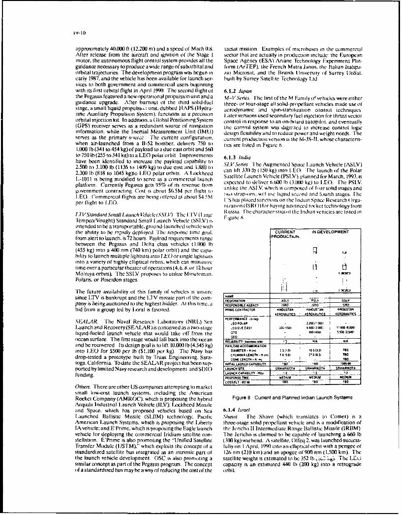
19-|0
approximately 400J00 ft (12.200 m) and a speed of Mach 0.8. icaat mission. Examples of microbuses in the commercialAfter release from the aircraft and ignition of the Stage I bector that are actually in production include: the Europeanmotor, the autonomous flight control system provides all the Space Agency (ESA) Ariane 'l'echnology Expenment Plat-guidance necessary to produce awide range of suborbital and form (ArTEP), the French Matra Janus. the Italian Italspa-orbital trajectories. The development program was begun in zio Microsat. and thc British I Inversity of Surrey UoSat.early 1987. and the vehicle has been available for launch ser- built by Surrey Satellite Technology ltd.sices to both government and commercial users beginningwith its first orbital flight in April 1990. The second flight of 6.1.2 Japanthe Pegasus featured a newoperational propulsion unit and a l-V Sernes. The first of the M Family of vehicles were eitherguidance upgrade. After burnout of the third solid-fuel three- or four-stage all solid-propellant vehicles made use ofstage, a small liquid propulsio,. unit. dubbed HAPS (Hydra- aerodynamic and spin-stabilization control techniqueszinc Auxiliary Propulsion System). functions as a precision [Laterversions used secondary fuel injection for thrust vectororbital injection kit. In addition, a Global Positioning System control in response to an on-board autopilot, and eventually(GPS) receiver serves as a redundant source of navigation the control system was digitized to increase control logicinformation, while the Inertial Measurement Unit (IMIJ) design flexibility and to reduce power and wseight needs. Theserves as the primary surcc. The current configuration. current production version is the M-3S-Il.whosecharacteris-when air-launched from a 1B-52 bomber, delivers 750 to tics are listed in Figure 6.1.000 lb (341 to 454 kg) of payload to a due east orbit and 560to 750 lb (255 to341 kg)toa LEO polar orbit. Improvements 6.1.3 Indiahave been identified to increase the payload capability to SLVSes the Augmented Space Launch Vehicle (ASLV)2.500 to 3.100 lb (1136 to 1409 kg) to due cast and 1,88(1 to2.300 lb (818 to 1045 kg)to LEO polar orbits. A L ockheed can lift 330 lb (150Vkg) into lEO. tlhe launch of the Polar1.,-1011 is being modified to serve as a commercial launch Satellite I.aunch Vehicl (PSIV). planned fi)r March, 1993, isplatform. Currently Pegasus gets 95% of its revenue from expected to deliver wh.ich1 ib (3.Xs) kg) to sEO. the PSLnV.government contracting. Cost is about S6.5M per flight to unlke the ASLV, which is composed of four solid stages andLEO. Commercial flights are being offered at about $4 5M :mo strap-oms. will use liquid second and fourth stages. Iheper flight to IEO. ( S has placed sanctionson the Indian Space Research Orga-
ni/ation ( ISR() )lr buying advanced rocket technology from
1.7VStandard Smpall launttch t{'/iiclc (SSI.ý-) I'he LIV0 (Russia. Fhe characteristics of the Indian vehicles are listed in
"Iempco/Vought) Standard Small launch Vehicle (SSLV) is FigureS.
intended to be a transportable. ground-launched vehicle withthe ability to be rapidly deployed, The response time goal. CURRENT IN DEVELOPMENTfrom alert to launch. is 72 hours. Payload requirements range PROOUCTiuN.between the Pegasus and Delta class vehicles (1.(W0 Ih(455 kg) into a 400 nm (740 km) polar orbit) and the capa-bility to launch multiple lightsats into I.EOorsingle lighisai.sinto a variety of highly elliptical orbits, which can maximizetime over a particular theater ofoperations (4,6.8. or 12 hour IIMolniya orbits). The SSI.V proposes to utilize Minutenman. , ALIPolaris. or Poseidon stages. "
The future availability of this family of vehicles is unsure . --
since LTV is bankrupt and the I;V missile part of the corn- NAMEDESIGNATION ASLV PSLV GSLVpany is being auctioned to the highest bidder. At this hme. a RESPONSIELE AGENCY !SR 50O SRO
bid from a group led by IA)ral is favored. PRIME CONTRACTOR OINDUSTAN HINDUSTAN HINDUSTANAERQNAUTICS AER0ONAVMiS AERONAUTICS
PERFORMANCE .4b (kgSFIEAIAR. The Naval Research I.aboratory (NRL) Sea LEOPOLAR - 2.W.101Launchand Recovery(SEAlARR)isconceivedas a Iwo-stage L.EODio EAST 3o01 i 6i 6 000013 Qo0 17,600liquid-fueled launch vehicle that wouuld take off from the GT0- 990 14w sm 502,500)GEOocean surface. The first stage would fall back into the ocean REL0ABIL" .(ucemaW•50 N A WAand be recovered. Its design goal is to lift 10,0W0 lb (4,545 kg) PAYLOAD ACCOMMODATIONinto I.EO for $500 per lb ($1.100 per kg). The Navy has DiAMETER -RI[.1 33100 10,o.2•5 Too
CYLINDER LENGTH - RimW 992.f301 270(631 Teodrop-tested a prototype built by Truax Engineering, Sara- CoNE LENGTH -,f,1) - T0otoga. California. To date the SEALAR project has been sup- INmAL LAUNCH CAPABILffY 1907 99"2 1•46.ported bylimitedNavyresearchanddevelopment andSI)IO LAUNCH srTE SRiIHARiOTA SAisARiKOTA SRI9ARI(0A
funding. LAUNCH CA TryI -ft", .2 ' .2 . '.2
RESPONSE TIME MAEDIUM MEDIUM MCOS•IFLT -191 M TrO D D TED
Others. There are other US companies attempting to marketsmall low-cost launch systems. including the AmericanRocket Company (AMROC). which is proposing the hybrid Figure 8 Current and Planned Indian Launch SystemsAcquila Industrial Launch Vehicle (ILV); Lockheed Missileand Space. which has proposed vehicles based on Sea 6.1.4 LIraell.aunched Ballistic Missile (SLBM) technology; Pacific Shavit. The Shavit (which translates to Comet) is aAmerican Launch Systems, which is proposing the Liberly three-stage solid propellant vehicle and is a modification ofIA vehicle: and E'Prime. which is proposing the Eagle launch the Jericho Ii Intermediate Range Ballistic Missile (IRBM)vehicle for deploying the commercial Iridium satellite con- The Jericho is claimed to be capable of launching a 660 lbstellation. E'Prime is also promoting the "Unified Satellite (300 kg)warhead. A satellite. Offeq 2.was launched success-"Transfer Module (IJSTM),'" which exploits ihe concept of a fully on I April. 19)0 into an elliptical orbit with a perigee ofstandardized satellite bus integrated as an intrinsic part of 126 nm (210 km) and an apogee of 900 nm (1.500 km). Thethe launch vehicle development. OSC is also promoting a satellite weight is estimated to be 352 lh , iA.- ky). The LEUsimilar concept as part of the Pegasus program. The concept capacity is an estimated 440 lb (200 kg) into a retrogradeofa standardized bus may be a way of reducing the cost of the orbit.

19-11I
6.1.5 Brazil claimed that the combustion products of the Space ClipperVLS. The VLS launch system is a conventional solid propel- are non-polluting. Yuzhnoye also builds the 7Zenit commer-lant four-stage system developed from tlhe family of Sonda cial launcher. The Space Clipper concept is illustrated insounding rockets. It is designed to deliver 220 to 440 lb (100 Figure 9.to 200 kg) payloads into circular orbits ranging from 135 to540 nm (250 to 1,000 kin) at various inclinations. The nomi- PEGASUS_(USAnal payload is 150 kg into a 750 km circular equatorial orbit.
6.2 Future Planned and Proposed ____ _________ -___ ,
6.2.1 AustraliaA consortium of Australian companies led by British Aero-space. Australia. Ltd is engaged in supporting a joint venturebetween Auspace Pty Ltd and Hawker de Havilland Ltd todevelop the Southern Launch Vehicle (SLV) (sometimes re- SPACE CLIPPER (CIS)ferred to as the Australian Launch Vehicle). The SLV is seenas a carrier of small satellites into LEO with payloads up to1.5 tonnes. The Association of Australian Aerospace Indus- .: . - d.- iJ .J, '.r-,es has also suggested the development of a lightsat plat- --form based on the proven British UoSat microsatellite tech-nology. Initial launches would be made from Woomera. butif the Cape York facility is developed, launches could takeplace from there too. Eight to 10 launches per year are Figure 9. Air-Borne kMc•.;!e Launch Vehiclesprojected.
7. BALLISTIC MISSILE-DERIVED lAUNCllSYSTEMS
6.2.2 United KingdomlNorway As a result of the [JS/(CIS Strategic Arms Reduction TalksLittleLauncherforLowEanhOrbit(LittLEO). The commer- (START) aigreemcnts. the use of surplus strategic ballisticcial LittLEO program is being undertaken by General Tech- missiles for launching tacsats needs to he considered. Therenology Systems Ltd and the Norwegian Space Center(Norsk are, of course, many issues that must be addressed in deter-Romsenter) to offer a low-cost and reliable means of placing mining the practicality and advantages of this option. Thesmall payloads into both polar and sun-synchronous orbits factors include the latest trends in the arms reduction talks in
um a AEuropean launcii site. The LittLEO is a solid propel- terms of determining the types and numbers of strategic bat-lantvehiclecapableofplacinga 1.3201b (600 kg) payload into listic missiles that might become available and any treatya 243 nm (450 km) polar orbit or 1,547 lb (703 kg) into a restrictionson theiruse asspace launchers: the payloadcapa-162 nm (300 km) polar orbit. It would be launched from the bility to typical orbits of interest and the payload compart-Andoya Rocket Range (69 deg 17 min N. 16 deg 01 min E). ment d "iensions: and estimates of the non-recurnng andMore than 400 sounding rockets have been launched from recurri costs. With respect to launch responsiveness, thethis site. LittLEO could also launch 2,006 lb (912 kg) into a land-based ballistic missile on alert status represents the ulti-162 nm (300 km) polar orbit from Italy's San Marco launch mate. with response times in the order of seconds. The costsite. and other issues related to maintaining this type of capability
presents the limiting case of launch responsiveness.
6.2.3 Spain The trend in the strategic nuclear warhead reduction talks isCapricornio. The Instituto Nacional De Tecnica Aerospacial for both the US and the CIS to go in two phases from the cur-(INTA) has announced a new rocket development, the rent total count for all three legs of the Triad of somewhatCapricornio. which is intended to provide low-cost space more than 10.000 warheads to 3100-3.500 warheads by thetransportation for the scientific and communications coin- year 2003. Tl'he first phase reduces the total number of war-munity. It is a three-stage all-solid rocket capable of placing heads to 3,800-4,250 in seven years or less from the execu-l10 to 220lb (50 to 100kg)intoa324nm(600km)polarorbit. tion date of the treaty Within these overall Triad limits,Tests will be conducted from El Arenosillo (Huelva). and there are specific limits placed on the Intercontinental Ballis-there are plans to budd a future launch complex in the tic Missile (ICBM) and Sea Launched Ballistic MissileCanary Islands. (SLBM) forces. At the end of the first phase, the number of
ICBMs cannot exceed 1.200. and the number of SLBMs can-not exceed 2160, for the second phase these limits are 1,200
6.2.4 Conmmonwealth of Independent States (CIS) and 1.750. respectively. In the second phase there is also aSpace Clipper. Yuzhnoye NPO, based in the Ukraine. is pro- requirement that all the remaining ICBMs carry only oneposing an air-launched commercial launch system, spaceclip- warhead each, while the SI.BMs can continue to carry multi-per. which is planned to be available in 1994. The system pIe warheads.consists of an An-124 earner aircraft and a choice of severalthree- or four-stage solid propellant launch vehicles (derived 7.1 United Statesfrom the SS-24 missile) that are launched from the cargobay Within the limits outlined above, there are still a large num-of the An-124. A choice of six different solid rocket launchers ber of possible distributions of specific missile reductions andhas been proposed. The baseline system is capable of deliv- therefore of their availability for space launch. However. asering 1.100 lb (500 kg) to LEO and is modularized to provide far as US missiles are concerned. Table 3 shows a generallysix different versions of the vehicle and adapt to a wide van- accepted retirement schedule and indicates that, betweenety of orbital requirements. The maximum takeoff weight is now and the year 2000-2003. the Minuteman !Is (MM-IIs)392 tonnes, and the system is claimed to be able to operate and the Navy Poseidon C-3 and Trident C-4 missiles will befrom any airfield capable of servicing a Boeing 747. To avoid retired and may be available for other applications. Aftertechnology transfer restrictions, the installation of the pay- that time period, the Treaty will require Peacekeeper missilesload can be performed on-board the Antonov at the custom- to be retired because of Multiple Independently-Targeteder's airfield. Yuzhnoye plans to modify two An- i24 aircraft. Reentry Vehicle (MIRV) limitations and specific de-MIRV-and there are more than 100 SS-24s in inventory. It is ing rules. The exact number of Peacekeepers that would be
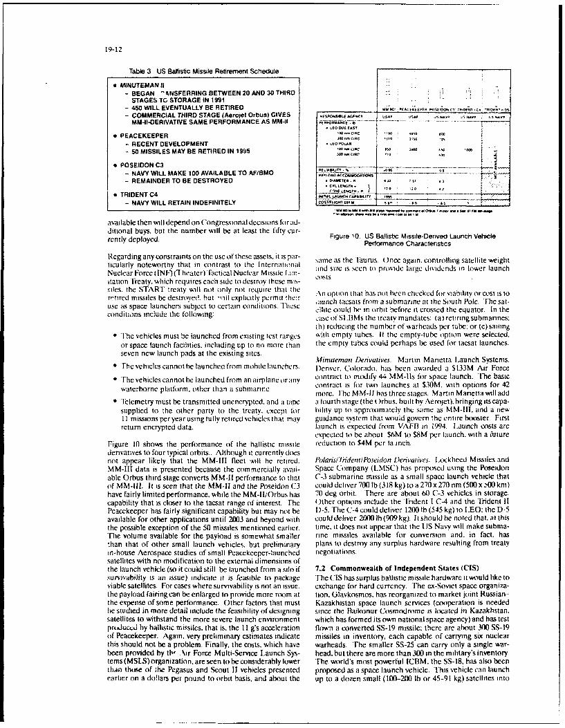
19-12
Table 3 US Ballistic Missile Retirement Schedule
0 MINUTEMAN II- BEGAN ' ANSFERRING BETWEEN 20 AND 30 THIRD
STAGES TC STORAGE IN 1991- 450 WILL EVENTUALLY BE RETIRED poccru . .. c, !*,O;,, ! 0, . 5
- COMMERCIAL THIRD STAGE (Aerojet Orbus) GIVES s ., , *, ,MM-I-DERIVATIVE SAME PERFORMANCE AS MM-Il 1ioosu....
.2 DUO E EAST
* PEACEKEEPER "*, c- RECENT DEVELOPMENT to- 50 MISSILES MAY BE RETIRED IN 1995 W , "PC . .
* POSEIDON C3 • --
- NAVY WILL MAKE 100 AVAILABLE TO AF/BMO PAYLOAD A- j. 0 o) S •,- REMAINDER TO BE DESTROYED * oWT2-. ,2 4
S.... .EG . } 2 2 ". *
T R I D E N T C 4 CO ME _ _ _ _ _ _ _ _
- NAVY WILL RETAIN INDEFINITELY ICOSTtIGM It, M s ,0 ,1
available then will depend on Congressional decisions for ad-ditional buys, but the number will be at least the fifty cur-rently deployed. Figure 10. US Ballistic Missile-Denved Launch Vehicle
Performance Charactenstics
Regarding any constraints on the use of these assets, it is par- same as the Taurus. (nce again, controlling satellite weightticularly noteworthy that in contrast to the Internatonal and si-u is seen toa prosid large dvtrldlnds i lower launch
Nuclear Force (INF)l'heater) Tactical Nuclear Missile l.an- c,•sis s
itation Treaty, which requires each side to destroy these mis-
siles, the START treaty will not only not require that theretired missiles be destroved. but -oll explicitly permit the:r .\noption that hasnot heenchecked forviabilityorcost isto
e as s e - iaunch tacsais from a submarine at the South Pole. The sal-use as space launchers subject to certain conditions. l'hfli cllitc could he in orbit before it crossed the equator. In theconditions include the f'ollowing: case ot SIMIlMs the treaty mandates: (a) retiring submannes;
(h) reducing the number of warheads per tube. or (c) saiing"* The vehicles must be launched from existing test ranges xith empty tubes. If the empty-tube option were selected.
or space launch facilities, including up to no more than the empty tubes could perhaps be used for tacsat launches.
seven new launch pads at the existing sites.Minuteman Defivatives. Martin Marietta LIaunch Systems.
"• The vehicles cannot be launched from mobile launchers. Denver. Colorado. has been awarded a S133M Air Force
"* The vehicles cannot be launched from an airplane orany contract to molify 44 MM-lls for space launch. The basic
waterhorne platform. other than a submarine. contract Is for two launches at $30M. with options for 42more. [he MM-11 has three stages. Martin Manietta will add
T eizlemetry must be transmitted uncncrypted. and a tape a fourth stage (the )rbus. built hy Aerojet). hnnging itscapa-supplied to the other party to the treaty, except for hility up to approximately the same as MM-Ill, and a new11 missions peryearusing fully retired vehicles that may guidance system that would govern the entire booster- Firstreturn encrypted data. launch is expected from VAFIH in 1994. L.aunch costs are
expected to be about $6M to $8M per launch, with a futureFigure 10 shows the performance of the ballistic missile reduction to $4M per la rnch.denvatives to four typical orbits.. Although it currently doesnot appear likely that the MM-Ill fleet sinll he retired. Polans/TndentiPoseidon I)envatives. L.ckheed Missiles andMM-Il data is presented because the commercially avail- Space Company (LMSC) has proposed using the Poseidonable Orbus third stage converts MM-Il performance to that (C-3 submarine missile as a small space launch vehicle thatof MM-111. It is seen that the MM-Il and the Poseidon C3 could deliver 700 lb (318 kg) to a 270 x 270 nm (500 x -NM km)have fairly limited performance, while the MM-IliOrbus has 70 deg orbit. There are about 60 C-3 vehicles in storage.capability that is closer to the tacsat range of interest. The Other options include the Trident I C-4 and the Trident IIPeacekeeper has fairly significant capability but may not be D)-5. The C-4 could deliver 1200 lb (545 kg) to I.EO; the D-5available for other applications until 2003 and beyond with could deliver 2000 Ib (909 kg). It should be noted that, at thisthe possible exception of the 50 missiles mentioned earlier, time, it does not appear that the UJS Navy will make subma-The volume available for the payload is somewhat smaller rine missiles available for conversion and, in fact. hasthan that of other small launch vehicles, but preliminary plans to destroy any surplus hardware resulting from treatyin-house Aerospace studies of small Peacekeeper-launched negotiations.satellites with no modification to the external dimensions ofthe launch vehicle (so it could still be launched from a silo if 7.2 Commonwealth of Independent States (CIS)survivability is an issue) indicate it is feasible to package The CIS has surplus ballistic missile hardware itwould like toviable satellites. For cases where survivability is not an issue. exchange for hard currency. The ex-Soviet space organiza-the payload fairing can be enlarged to provide more room at tion. Glavkosmos. has reorganized to market joint Russian-the expense of some performance. Other factors that must Kazakhistan space launch services (cooperation is neededbe studied in more detail include the feasibility of designing since the Baikonur Cosmodrome is located in Kazakhstan.satellites to withstand the more severe launch environment which has formed its own national space agency) and has testprtducAtd by ballistic missiles, that is. the II g's acceleration flown a converted SS-19 missile: there are about 300 SS-19of Peacekeeper. Again. very preliminary estimates indicate missiles in inventory, each capable of carrying six nuclearthis should not be a problem. Finally, the costs, which have warheads. The smaller SS-25 can carry only a single war-been provided by th, Air Force Multi-Service Launch Sys- head, but there are more than 300 in the military's inventory.tems (MSLS)organization. are seen to be considerably lower The world's most powerful ICBM. the SS-18, has also beenthan those of the Pegasus and Scout 11 vehicles presented proposed as a space launch vehicle. This vehicle can launchearlier on a dollars per pound to orbit basis, and about the up to a dozen small (100-2X0) lb or 45-91 kg) satellites into

19-13
orbit for less than $30 and is claimed to have all-weather would be focused (in building a prototype operationalcapability, There are estimated to be more than AX) SS-18 rocket-powered SSTO vehicle.missiles in the CIS. START calls for a 1lX)% reduction inthat force. 8.1.2 Tio-Siage-lb-Orbit (T.STO)
Several US contractors have presented plans for developingThere is concern on the part of the I IS commercial space a t•'o-Stage-lo-Orbit (TSTO) system wherc •ither one orlaunch industry that the ex-Sovict surplus space hardware both stages arc fully reusable. Although such concepts havewill be dumped on the world market. This may justify a US been under study since the early 1960s. they are presentlyaigreement to convert the ex-Soviet surplus ballistic missiles only contractor Independent Research and Developmentthat are not destined for destruction into space launchers (IR&D) programs in the very early concept explorationthat are held in reserve and only launched in the common phase of acquisition.interest of world peace. in rcsponse to critical theaterwarfareneeds. 8. 1.3 National AeroSpace Plane (NASP)
[he NASP Program has the overall goal of providing the7.3 Europe technological basis for future hypersonic flight vehicles for7.3.1 United Kingdomn (UK) application to both civilian and military systems Currently.Malcolm Rifkind. a defence secretary in the llritish Ministry because of budget constraints, funding is being focused on
of l)efence. announced on June 15. 1992. that the only nu- power plant technology. The N.A.SP propulsion systems are
clearweapons Britain will retain will be a handful ofWE-177 to be largely air-breathing. consisting of combined ram-
gravity bombs (as part of its commitment to NATO) and its jet-scramlet engines fueled by slush hydrogen. The X-30 isstrategic Polaris missiles. There is a debate over what, if any- not a prototype of any specific military or civilian system butthing. should be done about the Polaris-replacing trident will be used to demonstrate the requisite technology for suchprogram that is scheduled to carry 128 nuclear warheads on PCture systems, including arplanes ,ith hypersonc cruise16 Trident missiles. If the Trident program is continued as capability and fully reusable launch vehicles for payloadpresently scheduled, it is possible that some surplus British delivery to orbit. these vehcles will use conentional run-Polaris missile components will become available. although ways br takeoff and landing . Nationai \croSpacc Planethey will probably become part of the lIS inventory (NASH Derived Vehicle (Nj)V) woauld be an operational
follow-on to NASP An Interim NASP that would fly opera-
7.3.2 France tional sub-orhital advanced taesat missions has been sug-gested as a candidate for supporting tlesat missions that
France has not released a policy statement on the future ot could evolve in the next century The NASP concept is illus-any French surplus ballistic missiles. irated i Figure Il.
7.4 OthersIt is possible that both China and the CIS could, in the future. HOTOL(UK)market ballistic missiles to developing nations. [he futurewill probably see a proliferation of ballistic missiles through-out the world. China. for instance, has a large inventory.which it has shown no inclination to reduce. Other smallercountries that feel threatened by their neighbors are morelikely to add to. rather than reduce, their inventory of ballisticmissiles. The wide availability of these weapons couldencourage the rise of dangerous despotic regimes anywherein the world, and establishes a strong case for conducting NASP (USA)detailed tacsat studies.
8. FAR-TERM lAUNCH SYSTEMSI'hc emphasis of this paper is on current or near-term launchsystem options. However. tacsat studies also need to look Figure 11 Representative Horizontal Take-off Single Stageinto the next century. when the need for such systems may Launch Vehiclesintensify. A number of advanced systems are being investi-gated that may have application to future tacsat missions. 8.2 Europe
Several European nations are investigating advanced fully or8.1 United States partially reusable launch vehicles that may eventually need8.1.1 Single-Stage-'lb-Orbit (SSTO) to be considered as space launchers for tacsat missions.A single-stage-to-orbit vehicle has long been the desire of the major ones being France. Germany, and the Unitedmany space transportation planners because of its potential Kingdom.for reducing operational complexity and cost, and providinglaunch-on-demand capability for critical military systems. 8.2.1 GermanyThe SDIO has examined a number of sSrO configurations Sanger. The Sanger is a reference concept for the Germanto satisfy postulated SDIO mission launch requirements. and Hypersonics Technology Program. Currently the vehicleselected the McDonnell Douglas D)elta Clipper for further concept is a two-stage fully reusable system. The programstudy. Fhe Single-Stage-Rocket TIechnology (SSRT) Pro- was initiated in 1988 and will be executed in several consecu-gram is now underway at McDonnell Douglas to validate tive phases. The current Phase I is planned to continue untilsome of the critical technologies. A sub-orbital flight from the end of 1992. with a possible extension of two to threeWhite Sands is planned for 1993. years. The results of the program so far have confirmed the
reference Sanger concept theoretically and experimentally.lhe generic SSTO concept hassome technological aspects in Only one change has been made to replace the expendablecommon with the National Aerospace Plane (NASP) pro- cargo version of the second stage by a reusable unmannedgram described below. However. the long-term NASP effort version. The program is increasing the participation of inter-(the X-30 program) is focused on building an air-breathing national partners. which should lead to a program proposalSSTO technology demonstrator, with plans for a to ESA. Benefitsofthe Sangerconcept are that it would pro-NASP-derived operational vehicle, whereas the SSTO effort vide a launch capability from continental Europe. and its

19-14
mobility would permit it to take advantage of equatonal flight of a hydrogen-lueled scramjet engine. [he test flightlaunch of the final stage. The Sanger concept is illustrated in was of a missile-like vehicle powered by a conventionalFigure 12. rocket engine to an altitude of about 16 nm (30 km). A ramjet
engine then Ignited and accelerated the vehicle to a speed ofMach 6. During the flight, superomnic combustion occurred.
•N-i21NTERIM IIOTOL (UK/ClS) Attempts are being made to market ex-Soviet resources toother nations, such as the US. France. Germany, and Japan
.- Several other nations, including France. Japan. and Indiahave examined advanced reusable vehicles, both twto-stage
.. and single-stage. The world-wide decreasing space budgets, vwill make international cooperative ventures most likely in
-. -7- -- -.. the future.
9. IAUNCII SITE CONSII)ERATIONSThe orbit requirements for the GEO and LEO missions dis-"cussed earlier can be met by launching from the two mainSANGER (Germany). launch sites in the IU S, Cape Canaveral in Flonda, and Van-
- -•-_ ._- • . .-. denberg in California. Figure 13 shows the orbit inclinations
that are achievable from each of the two sites. All targets atinclinations equal to or less than 57 deg can he reached fromCape Canaveral, while the higher inclination orbits , includ-
Figure 12. Repfesentatve Horizontal Ta-f Ing polar and sun-synchronous. are accessible from Vanden-
Two-Stage Vehicles berg. The Atlas or D)elta bxosters %,isu id launch the G EO sat-ellites due east out of Cape Canaveral. while single I.EO
8.2.2 United Kingdom satellites could be launched on the small launch vehicles orballistic missile-derivatives from either launch site. LoargeHorizontal Take-Off and Lndins cHOetOL). The -rigi na multi-satellite constellations, such as Iridium-like concepts
ambitious HOTO. program is currently unfundedD lta or tlas out t Vandenberengine concept for the HOTOL developed and patented byAlan Bond has been declassified. but the Rolls-Royce \n Atlas II padisbeingbuilt at Vandenberg Fortheballistic
d ie inmssile-derivatives. the launch site at Cape Canaveral ,wouidRB5454 design is still held proprietary.. I he engine is a have to be re-activated, and dedicated launch sttes wouldpre-cooled, air-breathing rocket that utilizes air entering need to he established at Vandenberg [he estimatedthrough a V-wedged intake. The air is shocked down to sub- cost for an alxwc-ground balhstic missic-dcnvatie spacesonic speeds and passed through a series of beat exchangers launcher pad is about $S5M. [he air-mobile Pegasus offersand turbocompressors until it reaches rocket chamber pros- launch platform survivability and the maximum flexibiliiy nsures. Liquid hydrogen and liquified air fuel the first phase of launch site location and orbit nclhnathon. An advmantage 1tengine flight up to Mach 5.5 at an altitude of 98.4301 ft (3110k) the Pega.sus s that for target.ares at latitude. lower than theOnboard liquid oxygen and hydrogen is used for the remain- the deg (u iape Canaveral. launching at icinations equal toder of the flight. HOTOL shares technology needs with the the target latitude provides an laruit that inclinathe satelliteUJS NASP but its future is uncertain. It is illustrated inFigure b ifrmore consecutive passes over the target than the two timesFigure 1 . per day achievable if it were launched from Cape Canaveral
It should be noted that a cost penalty is incurred to exploit8.3 United Kingdom/Russia this advantage.Interim HOTOL A joint British/Russian development to flyan interim version of the British HOTOI, on the Russian Iable 4 lists the crwdinates of most of the space launch sitesAntonov-225 "MPIR" heavy lift aircraft is underway Succes- that exist(or i some eases are planned or are iactie) i ihesful wind-tunnel tests at simulated speeds of Mach 110.5 and whorld, and Figure 14 shows their distibutton. [he fluid14 have been conducted at the Central Aerohydrodyvnamicts global environment that is hound to exist in the future andInstitute(FsAGI)intheirF-28windtunnelinMoscow. [he the fact that tacsat mission will most likely he multinationalthree organizations have signed agreements among them- in nature (and perhaps a UN responsibility) require the con-selves as well as with their respective governments. British sideration of sharing launch facilities. [he Italian site at SanAerospace is defining the Acrospaceplane and airborne Marcos. off the coast of Kenya. the French site at Kourou.support systems. limited resources are available, but the French Guiana. and the Brazilian silte at Alcantara are inter-European Community Commission has been approached by esting because they afford the direct launch inclination orbitsBritish Aerospace for support since the commission has said for lower latitude targets. The relocatable Iaurus would be ait would entertain joint European/Soviet (now (IS) aero- candidate for using non-US launch sites but, again, aspace ventures, cost-effectiveness analysis would need to be carried out. The
U.S. Pegasus, the proposed (IS Space Clipper commercialThe vehicle is planned to carry a payload of 15.4(X) to orbital injection system, the IjKCIS Interim I )TOL. and17.600 lb (7,0WX to 8.000 kg) into LEO after being launched the German Sanger could also be launched from multiplefrom the An-22i at an altitude of about 29.5W) ft (9km). The launch sites.An-225 requires the addition of two extra Soviet D)-18engines. Rolls Royce replacement engines were considered 10. CONCIUSIONS/RECOMMEN DATIONSto avoid installing additional engines but was rejected as not While it is next to impossible to predict with certamty thea cost-effective modification. The concept is illustrated in Whileit is ne tt oe t ped certaintyFigure 12. environment of the future and what peacekeepig militar*
capability will be demanded in that environment . there are
8.4 Others some things that, in the long-term, appear inevitable:
The ex-Soviet Union has conducted advanced partially andfully reusable vehicle research and testing for many years. In * There will be a proliferation of high technology weaponNovember, 1991. for instance, the Cen:ral Institute of Avi- systems around the world in the hands of nation-statesation Motors. Moscow. claims to have conducted the first test that had not previously had access to such weapons.

VANDENBERG AIR FORCE BASE KENNEDY SPACE CENTER Table 4 Global Fixed Space Launch Sites
I8 -A SITES "'I6~3..'b
UTIfSCN C*! RA06GI
*1 3155 lST 5*05 MCCSSOoNAUTAT . St -C ]
' .I(ST .. If
36 'SIC * ELOSAACm I+~ "WAI. I ". mt 1S" t
. tA0~ TEST l"C -I . SA-APS S "J * : " 1*
F*u e i UInNCULSc h S te , (1*,,-• . + + - a.•"' ' " " I+
C 4TIC6#6.~~~ i~ ICES LATS 5,34 sa ~ A
ZiMACC ASO CS6 ZCA. s 4
I
Nc . .. ..... .I
Thllty to deliver devices of mass destruction. i c , chCClC sooetu "UNC"
c a l , *)i ol o g i clt . a n d. n u c l e a r d eI flA O AI' .11.( 1 tC
"" M ny oi the c ountries that h a t"
such wc i ns '%%l haw - .
n attio na~lJ mlis that are in ondilct v,+ih thc:mttcret, si. i ihw,,,+-+, :..., _ m _.+..
I':S. its. N..\IR ,tlhcs. and oth e'r riatnonrt ickfica;tc kl !,I ,o+ .+-., ••+ .m
.)(,m e (it th eQ countrir•s Ah oC h a such A(illon N '6%1C1 h.
,tedicatcd to vo+trld te+trnmr.•, ;n;, oitrni.'' oI[.C n 0.1f -P7vtm-l•+ ,": . " "
th eir n e.ightkir• anod. I r inte.rnal civil .,trueL ,.tru ,:Ii% c' i, • ,,.,...,...,,, ,.o -.... • .
t h e i n t e r e s t s ( it i, % or l d p e aI c e " • + " " " ' ' ' " " ' + " ' +
9 0 3 0 6 0 9 0 1 2 0 I S O 1 8 0 IS O 1 2 0 9 0 F O 3 0 09 0
.- URAT- v- V-- - - - -
W O OW
A•LO PS
•
C"6 * # 4
-30 ho giM,1cal. anI nucENEr dI, It ,CANSVER 30
X E9 AN T K NGA I T OW
It t Dsbt oG bla hCe
ManyAIKTA K1tecutre hthvesc URossi Ois U .~SS 3 1
national ~ SA MARl th Cei itit~hte'trstii1'*S.2US C t~I~~ ~~ U.isNl lis n te ain idi~ts t C3
S ,1
.SS '~ 44
S A N M A R C OC C U S A 5U-4AC 6 *
0 0 5 0 12 53a 50 10 9 00 -30
90c9
60 30 90 AS Wm20 1 50. so IO It0 0 a
EIHN CONGITUDEL
Fgue1 DsrAEAibto of GlbJLunhSe

*Not only will such countries possess threateningi mIlitary Commercial 'loan Inc., PO Niux 179., Denver, (C)capabilities, they will also (eventually) po;ssess the sur- 801202. USAveillance and reconnaissance capabilities to observe US 10. Iiian IV Users HIandbook. June 1987. 1 itan IV Spaceand allied activities and be able to deliver tluir weaporns Launch Systems. Martin Marietta. Decnver Aerospace.at long range with precision. PO. BOX 179. Decnver. Ct) 81)201. 1 1SA*
* T'ie response to unwarranted aggressive behavior. in or-der to be effective, will have to be very rapid multina- 1 1.. InltC/'itia Space l)itrecorv (Previously Jane's Spaceeflighttional action, resulting in severe coordination prob- D~irectory) 1991-92. Editcd by Andrew Wilson. Jane'slems tn command, control, communication, mntelli- Information G;roup. Sentinal Hlouse, 163 Brightongence-gathering and distribution, and treaty and arms Road. (7Oulsdon. Surrey ('R5 2NFI. UJK.
controlverifiation.12.. Interiaitional Reference Guide to Space L~aunch S ' ,re~ns.f~hse hanin enirometalconitons whchare conjec- 191YI Edition. Prepared by Steven J lsakowitz in coolyer-
tured to evolve over the next thirty years. place increasingly, 1'chnwithl ComtteeA./ Spubised Fanddistribute bysthemdemanding requirements on tactical orbital systems and Amerhican Institute ofbliAeroatc and Aistronautidcb.hhence on responsive launch services. T-he integrated need eAmericpan " Insi nter 370 A ernauisand P orom nadeicsW.for launch services, ranging from small current launch 'hAeopcCntr37 :ni PmnaeSvehicles, such as Scout, to advanced future launch systems, Washington. DC 2(X)24-25 18. USA.-such as NASP, must be assessed in the light of the expected 13.. Fl'lglievina. Robin, ct al. "Survey ot Foreign Launchnear-term and far-term tactical mission requirements. "'[his Vhce" ASR 25JfesnDvsHgwypaper characterizes the range of launch services that could Arlington. VA 2220)2. Space kechnology D)ivision Not Iesatisfy tacsat needs and documents the best available I nfor- S'FDN 91-17 October 1W91mation on the corresponding launch systems. It is concludedthat the tacsat missions identified herein can he adcq~uatclv 4.i rinane 4 A.'rianespacc. Inc. 1747 Pennsylvania Avenue.suppoirted by US launch vehicles launched fromn the conti- N W.. Suite 875. Washington. l)C21XXW6, Ariane Launchriental US. i loutvvr. numerous other options are available Vhidecs, rue St ijenitsyns. 9I 0(X) Evry. France.and need caretul study by the tacsat designer or planner. Abibliography is provided to identify additional source inatcri- i5 ,Sovi'i( l.aunchcr Prntoni ( ilavco~isro, 1(0303(0, MoscowýAl on some of the launch systems. Krasniiproletarskas'a str . 1), Russia.
11. Bibliography P) . 'i.imion Plunnien Manual, Proton Commercial L.aunchI.- ~esorsofite--istpa(-ll~. Iicrviapac~arets Vehicle. Space C'ommerce Corporation. 69th Floor.
I.. 19 1.eonot/elitSaearItrviSpcMrks Suite 6r900. 'Ii~xas Commerce liwer. olMI 'Iravis Street.4;1991.Houston, FX 77(X)2.
2- Newman. Frank. "FIictical Satellitcs". Presented at thc 17 I~i Mu~ l'dzilv of l.awitLh /i 'Uiicles. China (GreatNorth Atlantic 1'rcatv t )rganization (NAP( 3)Advisorv Wall Industry Corporation. 319 Palos Verdes Blvd 1318.Oroup for Aerospace Research and D~evelipment Redondo Reach. CA '.fl277. I JSA. China Great Wall(AGARDI) Avionics Panel Sym posiumotn lAt'S.'llSfio Industry C'orporation. No. 17. Wenchang Hutong Xi-Suirveillance. Verinfication andI ('3f. Brussels. Belgium. dlan. P6). (lox 847. Beijing. Peoples Republic of China.19-23 Oct. l'ý,'.
IS., 1/4I and If-Il Rocket NNASIA External RelationsG.(ipson, Melinda, and Richard IWunncke. Jr. M~icro- lDcpartment. 'World TFrade C'enter Building. 4-1 Hama-space Renaissance Pasha Publications Inc.. 1616 N. Ft. matsu-cbo-2-chome. Minato-Ku. 'lbkyo 1(05, Japan.Myer Dr.. Suite l(MX. Arlington, VA 222M9-3 1W). 1992.
19 Nationial Launch ,Si.itini (NI.S) Pan'Ioad Planning Hand-4.Files. WV S_. '1nited States Air Force Space Systems hook. Volumes [-VI. Prepared by I Awkheed Missiles
Division L~aunch Programs.' Paper IAF-92-0825. ;id nd Space ('ompany. Inc. Space Sys-tems D)ivision. POCongress ofi the International astronautical Federat~on. Pox 350)4. Sunnyvale. CA. 940389-35(04. Report No.Washington. 1) C. USA. 28 Aug-5 Sep. 1992.. I.MSC-P024791. 17 April 1992,
5. MV Litnh Sratgy tud Finl Rpor Prpard b 21.. Scout Pla,,,irini Guide. May 1986 l1AY Aerospace.TFhe Aerospace Corporatiion Space Launch Operations Vought Missiles and AdvancedI Programs Dirvision. P(.Programs Group for Space Systems Division. Air Force Box 6500)3. Dallas. FX 75265 -(XW)3. U SA.Systems Command. Aerospace Report No ''l'OR-92(2468fl. I5 April 1992. 21.Lockheed Standard L~aunch 1ý/ncle Mission Planning
(;uide. 20 December 1988. Prepared by Lo~ckheed Mis-6.. Aflas Mission Planners 61uide. Rev 1. March 1989. Gen siles & Space ('ompany, Inc. PO. Box 350)4 Sunnyvale,
eral Dynamics Commercial L~aunch Services. Inc.. 94.44 CA 94*3M-35034Balba Aenue Sute (K).Sanl~igo. A 9123 ISA 22. egasiss Payload Users Guide. Advanced Projects Office.
7. t~nrered Deta I Uier anul. uly 989 Mcon- Orbital Sciences Corporation. 12500 [Fair Lakes Cicle.nell Douglas Commercial Delta. Inc.. _5301 lBolsa Aye- -iraA203.U .nue. Huntington Beach. CA 92647. USA. 23.. Kniffen. R. J. and K. J. Flittie. American Rocket Com-
party. Camarillo. CA. I ISA. "I he D~evelopment of a8.. Payload Users Guide Tritan 11 Space L~aunchi Vehicle. 200.00 lb 'Ihrust Hybrid Roc.ket Boo~ster". Paper No.
August 1986. 'litan It Space Launch Vehicle Program, IAF-91-205. Presented at the 42nd Congress of theSpace Launch Systems D~ivision, Martin Marietta Cor- International Astronautical Federation, Montreal.poration. Denver Aerospace. PO. Blox 179. Denver, CO Canada. Oct. 5-I1. 1991.80201. USA.
24.. Liberty Launch Vehicle. Pacific American Launch Sys-9 'Titan Ill ('ommerrial Launch Services Cuslornur Hand- tems, Inc.. 10 'F'win D'olphin IDr.. Redwood City. CA
book Issue No 1. Deccember 1987. Martin Marietta 940)65

25., NPO "Yuzhnoye" Spa,:e Clipper. Contact: Y A, 28, lindlcy. C A. and I Penn. Ihc Acrospacc Corpora-Smetanin. Knvorozhskaya Sir 3, Dnetropetrovsk. lion. El Segundo. CA USA. "Combined Exo,Endoat-320059, Ukraine. SSR. lel: (0562)42 20 21. l'Iex: mospheric-lhansport Alternatives" Paper lAF-924W(3127 404 OREKH SU,. Fax: (0562) 42 20 21, 43rd Congress of the International astronautical Feder-
ation. Washington. 1) C. USA. 28 Aug-5 Sep 199226.. Space (.Cippe•i Commercial Orbital Injection System.
Principal ITechnical Characteristics. 'Yuzhnoye" 29. Wertz. James R and Wiley J. Larson (editors). SpaceDesign Office. 1991. Mission Analysis and Design. Kiuwer Academic Publish-
ers. Dordrechtlklston,,london. 1991.27.. Neiland. V. Ya., Central Aerohydrodynamics Institute
(TsAGI). Zhukowski. Russia. and R. C. Parkinson. Brnt- 30.. Space l'ansporralion Analists and fl).,n AerrApaceish Aerospace Space & Communications Ltd.. Steve- Corporation Report No. TIOR-92(2464 -I Prepared bynage, UK. "The An-225iIntenm Hotol Launch the AEROSPACECORPORATION, EiScgundo.CAVehicle. Paper No. IAF-91-197. Presented at the 42nd 191245-4691. 7 August 1992Congress of the International Astronautical Federa-tion, Montreal, Canada. Oct. 5-11. 1991. 31. National Academry, of Sciences. Nav'y 21 Study.

20-1
SPACECRAFT AND LAUNCH SYSTEMS FOR TACSAT APPLICATIONS
Chris Schade
Gilbert D. Rye
Robert H. MeurerOrbital Sciences Corporation/Space Systems
14119 Sullyfield CircleP.O. Box 10840
Chantilly. VA 22021
1. SUMMARY (4) high levels of responsiveness and flexibility for all systems:The abilityofa tacticalsatellite (TACSAT)space system to fulfill (5) situational awareness on a non-linear battlefield; (6) maneu-its mission application with the desired capability, responsive- verability; (7) coupling of national and theater levels of corn-ness. reliability and survivability, while at the same time achiev- mand. control, and intelligence: and finally (8)joint internationaling low cost objectives, is a tremendous challenge that can only operations.be met if all of the system segments - launch, space and ground -contribute to meeting mission unique requirements. The emerg- Some of our first insights into this new world of tomorrow'sing concepts for the development, deployment and operation of conflicts come from analysis of results of the Gulf War. One ofcost-effective TACSAT space systems are especially dependent the most dramatic was the importance of space systems to allon the flexibility and operability of their launch vehicle and aspects of the planning, execution, and success of this warspacecraft bus systems. Orbital Sciences Corporation (OSC) has Current space systems. which had evolved in support of the coldprivately developed two flexible yet cost-effective space launch wvar and strategic requirements. were called upon to providevehicles - Pegasus® and Taurusrm - with significant and unique direct support to tactical warfighters. Many htgh-*evel militaryoperational capabilities that enable TACSAT space systems to and civilian leaders characterized the conflict as the first "spacemeet these challenges. The Defense Advanced Research Projects warf - a war in which space systems were absoluiely essential toAgency(DARPA)hassponsored the first launchofboth systems. both the execution of the conflict and its success.with follow-on launches scheduled in support of U.S. Air Force,
NASA. SDIO and commercial programs. In addition. OSC has Thecapabilitiesof these current space systems to support a broaddeveloped a flexible, cost-effective, spacecraft bus - PegaStar"1 spectrum of tactical warfare mission areas was impressive con-- that makes common use of the Pegasus or Taurus final stage sidering their heritage, but in many cases, their lack of flexibilityavionics and structure in an integrated systems approach. thereby and responsiveness impeded their performance. If the six monthsoptimizing the mass and volume available for payload sensors. prior to the conflict had not been available to significantly adjustPegaStar spacecraft for the Air Force and NASA are now in and modify their space-based architectures and ground systems.engineering and production, the level of support would have been significantly degraded.
Also. if the conflict had extended in tune. some space assets
2. INTRODUCTION would have probably needed immediate replacement - whichThe world today is a different and changing place, characterized would have been very difficult due to the responsiveness andbydramatic andrapidly evolving newgeopolitical, economic and availability of spacecraft and launch vehicles.national security structures and relationships. In response, theUnited States' and its allies' national military strategies and These and other lessons from the Gulf War on space systemsnational security infrastructures that support them must now support to the tactical user will be the stimulus for the entiredepart from the principles that have shaped them since the end of national security community to re-evaluate the warfighting re-World WarII. These strategies and infrastructures, which evolved quirements for future space systems and the infrastructure neededtocontainthespreadofCommunismanddeterSovietaggression, to meet these requirements. The resulting future space systemsmust now shift dramatically to focus on regional crises and wars. will no doubt include TACSAT systems that will emphasize
flexibility, responsiveness and cost-effectiveness in meeting theThe threats of this new world can be best characterized as changing U.S. and Allied national security requirements. Many
unpredictable andcomplex - where will theyoccur, how fast must of the other papers in this symposium will probably address thebe the response, what will be the sophistication level of the architectures, requirements. sensor system, ground systems andweapons, who are the combatants, what are the political and employment strategies for these systems. Orbital Sciences Cor-
military goals, etc? The United States' military force structure for poration has developed two launch vehicles and a spacecraft-busemployment against these threats will be characterized by fewer that will provide flexible, responsive and cost-effective launchin number, more cost-effective systems, fewer forward-based and on-orbit performance for future TACSAT systems.elements, and much lower active-duty manpower.
3. PEGASUSThe operational imperatives to be addressed in the employment ofthese forces will be characterized by: (I) "come as you are" 3.1 Introductionconflict scenarios; (2) response to rapidly unfolding crises with The flight-proven Pegasus air-launched space booster (Figure 1)a few critical engagements; (3) long-range application of power: provides a cost-effective, reliable, and flexible means for deliv-
Presented at the AGARD Avionics Panel's Symposium on "TACSATS FOR SURVEI.LANCE. VERIFICATION and C31".Brussels. Belgium. 19 • 22 October. 1992.
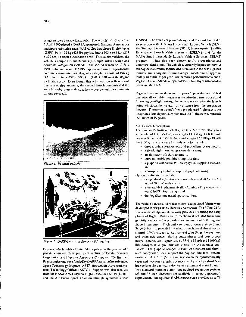
20-2
cring satellites into low Earth orbit. The vehicle's first launch on DARPA The vehicle's proven design and low cost have led to5 April 1990 placed a DARPA sponsored. National Aeronautics its selection as the UI.S. Air Force Small Launch Vehicle (SLV).and Space Administration (NASA) Goddard Space Flight Center the Strategic Defense Initiative (SDIO) Experimental Satellite(GSFC) built 192 kg (423 lb) payload into a 505 x 685 km (273 Expendable Launch Vehicle system (ESELVS) and for thex 370 nm)94 degree inclination orbit. This launch validated the NASA Small Expendable Launch Vehicle Services (SELVS)vehicle's unique air-launch concept, simple, robust design and program. It has also been chosen to fly intemaUonal andhorizontal integration methods. The second launch on 17 July commercialmissions. The vehicleiscurrendyinproductionwith1991 delivered seven DARP/. sponsored small experimental ten payloads currently manifested for launch in the next eighteencommunication satellites, (Figure 2) weighing a total of 196 kg months, and a targeted future average launch rate of approxi-(431 lbsI, into a 352 x 500 km (190 x 270 nm) 82 degree mately six vehicles per year. An increased performance versmon,inclination orbit. Even though this orbit was lower than desird Pegasus XL. is under development with a first flight scheduled todue to a staging anomaly, th,. second launch demonstrated the occur in late 1993.vehicle's robustness and capaoility to deploy multiple commnuni-cations payloads. Pegasus' unique air-launched approach provides unmatched
operational flexibility. Pegasus is mated to the carrier aircraft andfollowing pre-flight testing, the vehicle is carried to the launchpoint. which can be virtually any distance from the integrationlocation. The carrier aircraft flies a pre-planned flight path to thedesignated launch point at % hich tine the flight crew commandsthe launch tf Pegasus.
3.2 Vehicle DescriptionThe standard Pegasus vehicle i Figure 3) is 15.2 in (50 ft) long.hasa diameter ol 1.3 in 050 in), and weighs 19.000 kg (42.000 Ibm).Pegaus XI. i 17.4 in (57 ft) long and weighs 22.600kg (49.800
hini. Maior compontents for both vehicles include:* three graphite composite. solid-propellant rocket motors.
a fixed, high-mounted graphite delta wing.
an aluminum aft skirt assembly,* three moveable graphite compos,,ite fins.
Figure 1. Pegasus inflight. • a graphite composite avionics/payload support structure,and
.i a two-piece graphite comtpolite payload fairing.U O)ptional subsystems include.
tWo payload separation system,,. 51, cm and 98.5 cm) 23 3V6 4q~~i in and 38 8 in) in diamet er.
A . a restartable I lydrazmne, NIl 4) Aaxiliary Propulsion Sys-"tem ilIAPS). fourth stage and
* the PegaStar integrated spacecraft bus.
'Mite vehicle's three solid rocket motors and payload fairing wereAA , developed for Pegasus by Hercules Aerospace. T'he 6.7 m (22 ft)
span carbon composie delta wing provides lift dunng the earlyphases of flight. Th1ree electra-mechanical actuated foam coregraphite composite fins provide aerodynamic control throughoutStage I operation. Pitch and yaw control dunng Stage 2 andStage 3 burn is provided by eleciro-mechanical thrust vectorcontrol ('IVC) lctuators. Roll control alter Stage I separ.xion,and three-axis control during coast phases and post orbital
Figure 2 DARPA rnirosatsflown on F2 mission- insertion maneuvers. is provided by 55 N (12 5 lbhf and I10 N (25lbf) nitrogen cold gas thrusters located on the avionics sub-
Pegasus. which holds a United States patent, is the product of a system. The graphite composite avionics structure and alumi-privately funded, three year joint venture of Orbital Sciences num honeycomb deck support the payload and most vehicleCorporation and ilercules Aerospace Company. The first two avionics. A 1.3 m (50 in) outside diameter pyrotechnicallyPegasus missions werefunded by DARPA as partof its Advanced separated two-piece graphite composite clainshell payload fair-Space Technology Program (ASTP) through the Advanced Sys- ing i.ncloses the payload, avionics subsystem, and Stage 3 motor.tems Technology Offices (ASTO). Support was also received Two standard marmon clamp type payload separation systemsfrom the NASA Ames Dryden Flight Research Facility (DFRF) (23 and 38 inch diameter) are available to support spacecraftand the Air Force Space Division through agreements with deployment. The optionallIAPS, fourth stage provides up to73

'0)-3
Second/- Third Stage Carrier Aircraft
Avionics Separation Joint AttachmentsSection
Flexseal Thrust CablePayload X Vector Control - CableInterface Can/ -lS.... ./// , f .... . • , .... Channel
Col Ga / 1/ \
old Gas , Interstage Fin ActuatorsThrusters (6) - Stage3 \ Separation SeodFirst/S Mtorg • Joint Second Stage Stage 1 Motor
N2 Tank- Motor . Separation JointPayload Fairing Stage 2 Motor
Figure 3. Pegasus cutaway.
kg (160 Ibm)of N,1l1. for orbit raising and/or adjustment. Whencombined with the Pegasus standard on-boardGlobal PositioningSystem (GPS) receiver, tHAPS provides autonomous precisionorbit injection capability. The PegaStar integrated bus will bediscussed later.
The Pegasus avionics system is simple, robust, and reliable. Thevehicle's flight computer has two processo, s. A Motorola 68020Central Processing Unite (CPU) commands all flight events andexecutes the vehicle's autopilot program. A Motorola 68000CPU supports the autopilot processor and processes all vehicletelemetry. An inertial measurement unit (IMU) provides vehicleattitude, velocity and navigation information. All remote avion- WSJics units, which include Pyrotechnic Driver Unites (PDUs),Telemetry Multiplexors ( MUXs), Thruster Driver Units (TDIJs),and Thrust Vector/Fin Actuator Controllers, have integral micro-processors and communicate with the flight computer usingdigital RS-422 communication lines, All significant vehicle Figure 4 Horizontal vehicle and payload integrarion.performance parameters are transmitted to the ground duringflight using a single 56 kbps S-band telemetry channel. The six 3.4 Launch Operationschannel GPS receiver provides continuous position and velocity Pegasus launch operations combine launch vehicle and aircraftinformation to minimize the effects of IMU gyroscope drift and operations, with emphasis on simplicity, flexibility, and opera-accelerometer bias enrors. tional discipline. The launch location flexibility inherent in
Pegasus can significantly increase payload capability and orbital3.3 Vehicle Integration flexibility by eliminating many of the launch azimuth restrictionsFinal integration for Pegasus requires a minimum of ground often imposed by fixed launch sites. After integration, mating tosupport equipment (GSE) and facilities. Prior to being delivered a B-52 or L- 1011 carrier aircraft and pre-flight testing, the vehicleto the field integration site, all components are integrated and is carried to the launch point, which can be virtually any distancetested to the highest possible levels. The vehicle is integrated from the integration location. For launch, Pegasus is carried to ahorizontally (Figure 4). at a convenient working height which nominal level-flight drop condition of 12.200 m (40.000 ft) atallows easy access for component installation, inspection, and high subsonic velocity. After release, the vehicle free falls totest. Articulated transportation dollies eliminate all requirements clear the carrier aircraft, while executing a pitch-up maneuver tofor lifting motors in the field. Integration and test procedures achieve the proper attitude for motor ignition. After Stage Ienable vehicle components and subsystems to be thoroughly ignition, the vehicle follows an autonomously guided. lifting-tested before and after final flight connections are made. Several ascent trajectory to orbit. Future missions will incorporate GPS"fly to orbit" simulations which exercise all actuators and pyro- into the tracking and guidance system of Pegasus resulting in antechnic initiation outputs are conducted prior to launch. autonomous range capability.

20-4
3.5 Payload Capability and InterfacesPegasus' payload capabilities to polar orbits (assuming a 36 Pegasus' omn-inclination launch capability tespeciallv usingdegree launch latitude) are summarized in Figure 5. Information OSC's autonomous range concept) provides unique flexibility toregarding payload performance to elliptical and other incluiation meet mission requirements and eliminate doglegs. thus improv-orbits, payload services and payload environments can be found ing payload performance to orbit. This capability also providesin the Pegasus Payload User's Guide. The standard payload for first pass coverage of any point on the earth. Also of keyfairing (Figure 6) can support payloads as large as 2.21 m (87 in) operational importance is the minimal impact of weather onlong and 1.1 m (44 in) static diameter. The fairing can be Pegasus launch system availability. Other than typical aircraftextended in length 15cm(6in)incrementsupto60cm(24in)and flight limitations, flight to the drop point above most weatheraccess doors can be repositioned or added as optional services, systems is possible with a flexibility to adjust to new drop points
in real time. There are also no trajectory limitations due to upper3.6 Pegasus Operational Flexibility for TACSAT Applica- air winds, thus the Pegasus launch system readiness rates fartilots exceed ground launched systems.The Pegasus air-launched space system is unique in its capabili-ties to enable truly flexible, responsive, cost-effective access to The Pegasus launch system provides national security spacespace. These enabling capabilities, when combined with a system strategists and planners with unique capabilities ,%hich
modular spacecraft bus such as PegaStar and evolving sensor when combined with evolving small spacecraft bus and sensorconcepts, offer dramatic new possibilities in meeting the evolv- technologies, can enable flexible, responsive. co, -effective and.ing national security requirements of tomorrow's world. The in some cases. undreamedof suppon to the warfighters in meetingPegasus system can be integrated and operated from remote new and evolving national security requirements.secure airfields anywhere in the world due to its simplicity andminimal facilities and manpower needed. Dispersal of several 4. TAURUSPegasus systems over a wide geographic area could also providesurvivability levels unachievable by current launch systems. 4.1 Introduction
"The TaurusTM space booster has been developed to provide aWith pre-planned positioningof vehicles and facilities. a Pegasus capability to quickly and efficier-tly integrate a launch vehicle andlaunch could be called up in hours - not days - to support new payload for the rapid launch of small satellites from either aoperational needs or reconstitution of an on-orbit asset. Since no remote or fixed launch site. This ground transportable launchpad refurbishment is required, quick turnaround in hours - not system is erectable within five days of arrival at a "dry pad"
months-isalsopossible. Usingmorethanonecarrieraircraftaand launch site and. after set-up, respond to a launch-on-demandintegration facility would allow surges of multiple launches in a requirement within 72 hours. Initial launch capability of thesingle day if required. All of these scenarios for operational Taurus launch system will occur in the first half of 1993. Thefirstemploymentcouldbeaccomplishedbysmallmilitary orcontrac- flight of the laurus Standard Small Launch Vehicle (SSIV) istor teams.
800
750 Standard
"70 Standard & HAPS700 - - -........
" "...... XL6 5 0 .. ....................
60 XL & HAPSg 600
550
"C) 500
a" 450t1t
400
350 90 Degree Inclination
300 I I I i I I i 1 I 1 1 I 1100 150 200 250 300 350 400 450 500 550
Circular Altitude (nm)Figure 5. Pegrasus performance options to 90* inclination-

2o-5
sponsored by DARPA and will deliver a DoI) payload to a lowE-arth orbit. The launch vehicle and system developed to satisfy
Wo these DoD requirements has also been designed to respond toHarness Stayout Zone commercial launch service applicationsrequaxing better response
Pigfuals Clamp/Separation to meet market opportunities and with less bottom line impactCoSystem More capable Taurus configurations are being developed forComponents introduction in 1994.
90" 270' OSC has endeavored to develop user-finendly electrical andmechanical payload interfaces which facilitate integration of awide variety of payloads. The Taurus vehicle's simple, robustdesign ensures maximum reliability and significantly reduceslaunch site manpower testing and support infrastructure require-ments. Hlorizontal integration methods greatly simplify vehicle
1800 assembly and payload iitegratlon.038" Payload Separation System
Stayout Zone The Taurus space booster launch systeos currently in develop-mient as the SSLV for DARPA ;ý a four-tuee solid-fuel designcomposed of the flight-proven Pegasus motor stack and avionics
Fainng mounted on top of a [hiokol [1 J-903 l'cacekeepcr) solid rocketDynamic mnotor. IA "hiokol Castor 120 motor. •o" in test, will be used onEnvelope the commercial'"raurus . I'he 'Taurus .SI.V vsictn is composed
of a flight vehicle and ground suppxrt cquipment designed foreasy transportability and rapid setup and launch frorm an unim-
proved concrete pad or from a modest fixed gantru. All propul-(3 0 :3 3 ) sion elements of the DARPA Taurus senicle have been flight-
proven on the Pegasus or Peacekeeper programs [he remainingX Fairing Taurus subsvstems are virtually idcnt,:ai tIo those successfully
flown on the Pegasus vehicle.
The standard vehicle design, shown in Figure 7. incorporates six
tmajor elements: four solid fueled stages, a payload fairing and an.. avionics assembly. The Pegasus-derived motors retain their
Payload Stage 1. 2 and 3 designations from that program: the Thiokol87 O0 [Access
Cutout Castor 120 is designated Stage 0. TIhe vericle is designed to be
10(13.00 X integrated and tested at a launch site integration facility afterRCS 5.81) completion of all stage-level assembly and testing at the factory
47,00 Stayout This procedure is less complex and more cost-effective than the
25.00 0procedures required for larger ground-launched vehicles which5proceed through a full integrated factoo syiterr test followed by
ý disassembly into stages for shipment and subsequent reassemblyand second integrated systems test at the launch pad. With final
S-integration and testing only at the launch integration site. theTaurus approach minimizes the handling of the solid rocketmotorswhile simultaneously streamlining the vehicle acceptancetest process. Extensive factory testing by bith OSC and its vedorsensures that all hardware is ready for flight once it reaches the pad.®• Payload Interface Plane
Pegasus Station X: +584.93 A complete set of standard and optional services is available to(For Payload Separation System A20066) support specific payload requirements including: inertial orien-
(a Payload Interface Plane tation prior to separation: direct down-link of critical payload
Pegasus Station X: +580.98 telemetry during prelaunch operations and launch: electrical(For Non-separanrng Payloads) power for payload heaters and other payload components during
prelaunch operations: payload fairing access doors and Radio(0 38' Avionics Thrust Tube (22.00' Long) Frequency (RF) windows: filtered, conditioned air and dry
nitrogen for purge of the payload environment during launch
integrations.Figure 6. Standard and XL payload fairing dynamic envelopewith 38" diameter payload interface. For launch, Taurus is transported to the launch site using a wide-
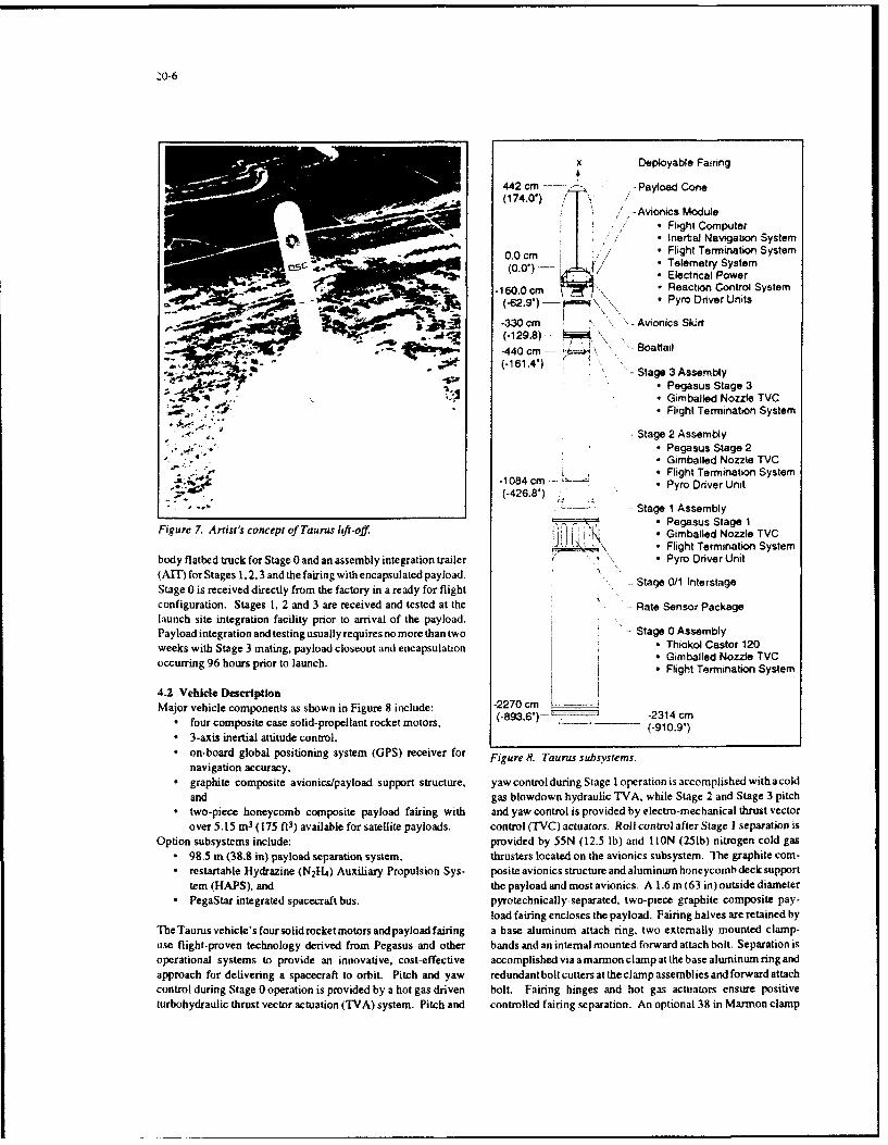
20-6
x Deployable Fairing
442 cm Payload Cone(174.0) ",- Avionics Module
S ,,/ Flight Computer"-/ * Ineral Navigation System
00 cm,/,* Flight Termination System(0.0") - * Telemetry System- Electrical Power
- ; , -160.0 cm , Reaction Control System(-62.9) Pyro Driver Units
-330 cm Avionics Skirt(.129.8)- L ,oatta\-440 cm '" • Boattail
• -*--- .- 440 cm -- ,
(-1814) "-Stage 3 Assembly* Pegasus Stage 3
. Gimballed Nozzle TVC- Flight Termination System
Stage 2 Assembly" Pegasus Stage 2- Gimballed Nozzle TVC
" ""084c m ,Flight Termination System
(-426.8') c Pyro Driver Unit
* -" -- Stage 1 Assembly- Pegasus Stage I
Figure 7. Artist's concept of Taurus lift-off. -L * Gimballed Nozzle TVC_ \_ - Flight Termination System
body flatbed truck for Stage 0 and an assembly integration trailer ' Pyro Driver Unit(AlT) for Stages 1, 2,3 and the fairing with encapsulated payload.Stage 0 is received directly from the factory in a ready for flight Stage 0/1 Interstageconfiguration. Stages 1, 2 and 3 are received and tested at the - Rate Sensor Packagelaunch site integration facility prior to arrival of the payload. S 0Payload integration and testing usually requires no more than two Stage 0 Assemblyweeks with Stage 3 mating, payload closeout and encapsulation . Thiokol Castor 120
- Gimballed Nozzle TVCoccurring 96 hours prior to launch. • Flight Termination System
4.2 Vehicle DescriptionMajor vehicle components as shown in Figure 8 include: -2270 cm
"• four composite case solid-propellant rocket motors. (-893,6)-- _ _ _-2314 cm(-910.9')"* 3-axis inertial attitude control."* on-board global positioning system (GPS) receiver for Figure 8. Taurus subsystems.
navigation accuracy,"* graphite composite avionics/payload support structure, yawcontrol during Stage I operation is accomplished with acold
and gas blowdown hydraulic TVA. while Stage 2 and Stage 3 pitch"* two-piece honeycomb composite payload fairing with and yaw control is provided by electro-mechanical thrust vector
over 5.15 m3 (175 ftW) available for satellite payloads. control (TVC) actuators. Roll control after Stage I separation isOption subsystems include: provided by 55N (12.5 Ib) and l ION (251b) nitrogen cold gas
* 98.5 m (38.8 in) payload separation system, thrusters located on the avionics subsystem. The graphite com-* restartable Hydrazine (N 21-4 ) Auxiliary Propulsion Sys- posite avionics structure andaluminum honeycomb deck support
tern (HAPS), and the payload and most avionics. A 1.6 m (63 in) outside diameter* PegaStar integrated spacecraft bus. pyrotechnically-separated. two-piece graphite composite pay-
load fairing encloses the payload. Fairing halves are retained byTheTaurus vehicle's four solidrocketmotors and payload fairing a base aluminum attach ring, two externally mounted clamp-use flight-proven technology derived from Pegasus and other bands and an internal mounted forward attach bolt. Separation isoperational systems to provide an innovative, cost-effective accomplished via amarmon clamp at the base aluminum ring andapproach for delivering a spacecraft to orbit. Pitch and yaw redundantbolt cutters at the clamp assemblies and forward attachcontrol during Stage 0 operation is provided by a hot gas driven bolt. Fairing hinges and hot gas actuators ensure positiveturbohydraulic thrust vector actuation (TVA) system. Pitch and controlled fairing separation. An optional 38 in Marmon clamp

payload separation system is available. 'Ihe optional I1APS 4.5 Payload Capability and Interfacesprovides up to 73 kg (160 lb) of N2 114 for orbit raising and PayloadcapabilityoftheDARPATiurusvehicle to some typicaladjustment. When combined with the Taurus standard on-board orbits is shown in Figure 9. The Taurus XL configuration uses theGlobal Positioning System (GPS) receiver, IIAPS provides au- Pegasus XL stretched motors and the ('astor 120 whereas thetonomous precision orbit injection capability. The optional Taurus XL/S adds two strap-on rocket motors to Stage 0. FigurePegaStar integrated spacecraft bus will be discussed later, 10 shows performance to a 90" orbit from Vandenberg- Specific
infcrmatuon regarding payload perfnomance to other orbits can beTheTaurus avionics system is simple, robust, and reliable. All of determined by contacting OSC's Office of Business D)evelop-the hardware components are identical to those used on Pegasus. mient. [le standard payload fairing can support payloads as largewith the exception of the addition of a reate gyro package to the as 2.82m ( 110 in) long and up to I 38m (54 in) in diameter (Figurebase of Stage I and harness modifications to accommodate Stage 1 ). Funded studies are in progress to address increasing the0. The software programs arc identical except for the addition of fairing diameter.Stage 0 function and mission peculiar modifications.
4.3 Vehicle Integration OrbitDARPA TaurusTaurus field integration is straightforward and requires a mini- Capabilitymum of launch support equipment (LSE) and facilities. All of theLSE is transportable and capable of setup at remote austere sites. 250 nrm, 280, 2450 lbsThe vehicle is integrated horizontally at a convenient working (Orion 38 Stg 3) (1114 kg)height which allows easy access for component installation, tc.,tand inspection. The use of standard serial RS-422 cominunica- Geosynchronous 860 lbstion protocols throughout simplifies vehicle wiring, streamlines Transfer (STAR 37 PKM) (391 kg)aviomcs testing and integration and significantly reduces test and ... ..custom LSE requirements. The integration and test proceN.s F'iurc V DARPA 'Ttm capabhl'vensures that all vehicles components and subsystems are thor-oughly tested before and after final flight connections are madeSeveral "fly to orbit" simulations exercise all actuators andpyrotechnic initiation outputs. Taurus integration activities are 1600
controlled by a comprehensive set of Work Packages (WPs) anid 32Procedural Guides (PGs), which describe and document in detail "every aspect of integrating the vehicle and its payload. 2 26400
4.4 Liaunch Operatiorns ; 800Taurus launches can be conducted from either of the D~epartment So160oof I)efense's Eastern or Western Ranges )FR/WR) as well as (.from the National Aeronautics and Space Administration I NASA) 400 . .Goddard Space Flight Center's GSFC) Wallops Flight Facility 880100 400 700 1000 1300 1600 1900f WFF) Range in Virginia. The first Taurus launch for DARPA is 54 216 378 540 702 864 1026scheduled for the first half of 1993 from Vandenburg AFB onto Altitude (km/nm)the Western Range using only a simple concrete pad to set up IIOSC's transportable launch support equipment. OSC's comner- Fiiure 10. Taurus conftiurotions pcrormarise to 9)Ocial Taurus launch service will be conducted utilizing a modest inclination.fixed gantry with a rotating service structure. OSC's primarycommercial Taurus launch facilities will be established at launch The Taurus vehicle offers a number of standard services. lhesites optimum for the particular mission being supported . standard l 6m (63 indiameterTaurus payload fairing offers overVandenburg AFB, CA: Wallops Island. VA and Cape Canaveral 5.15m 3 (175 ft3 ) for payload use. The fairing is designed toare likely locations. encaipulate the payload in a payload integration facility follow-
ing checkout. A class 10.000 environment can be maintainedA Taurus payload interface checkout facility is available as a inside this encapsulated cargo element (i-CEl at all times fromstandard service at OSC's Fairfax, VA engineenng facility for encapsulation through FCIF transpoxrt. vehicle integration and upinitial payload to launch vehicle functional test and checkout until launch. As a standard service. OSC provides one 12-inchI lousing an engineering test model of the laurus avionics assein- square access door in each half of the fairing. located to thebly and a complete set of avionics and payload test equipment, requirements of the payload. These doors provide all the access.this Vehicle Systems Integration ILAB (VSIL) will be used for the including late access on the gantry, to the payload once encapsu-development of mission peculiar launch vehicle software, quali- lation is completed. As an option. OSC can reposition the accessfication of mission peculiar avionics services and validation of doors, provide larger or additional access doors or RF-transpar-payload integration procedures and flightchecklists. The facility ent panels. The payload mechanical]y mounts to the standardwill also be equipped to conduct launch vehicle mission simula- Taurus separation system via 60 fasteners about a 38.81-inchtions with payload hardware and software in the loop. diameter bolt circle.

20-8
I - 10' --
63"'.
54'
Payload Dynamic
Payload Interface Envelope
0 860 0.25 Inch Fasteners(NAS 1351C4
View A-A
Figure 11. Taurus payload fairing dimensions.
The Taurus payload electrical interfaces are established through All of the at ive capabilities can support LEO as well as GEOthree connectors - power and signal, pyro. and RF. The power and missions. These Taurus launch system unique capabilitiescan besignal connector provides six payload passthroughs (prior to exploitedtodevelopandsupportinnovative.flexible.responsivelaunch), eight payload discrete commands, four payload discrete and cost-effective space systems to meet the new world require-talkbacks and a payload separation sensing breakwire. The ments of future space systems.power and signal connector also supports an optional payloadRS-422 telemetry stream. The pyro connector can initiate up to 5. PEGASTARTMfive redundant payload pyrotechnic events, In addition, the RFconnector supports payload RF transmission via the existing 5.1 Introduction
Taurus antenna system. Detailed information on payload ser- In 1989. OSC began work on several low-cost, multi-purposevices and payload environments provided by Taurus can be found spacecraft projects. One of these, the PegaStar integrated space-in the Taurus Users Guide available on request from OSC. craft bus is designed for use with Pegasus and Pegasus-derived
launch vehicles, including Taurus. PegaStar is a key element of4.6 Taurus Operational Flexibility for TACSAT Applica- the company's ability to offer comprehensive space launch andtions satellite services. Using many of the same systems that operateThe Taurus launch system, has attributes for flexible, responsive the Pegasus vehicle. PegaStar is being built around the third stageand cost-effective launch far beyond existing launch systems. of Pegasus (minus the motor which is separated after attainingWith its ground mobility and compatibility with air transport. orbit) to provide the "house-keeping" services necessary toTaurus can provide significant levels of survivability through support OS. or customer-provided instruments. communica-dispersal. This is greatly enhanced by the fact that Taurus can be tions devices and other sensors on-orbit. In early 1991, OSClaunched from an "unimproved, dry pad" - i.e.. the end of a entered into a contract with the U.S. Air Force Space Testrunway. The Taurus system has been designed and will demon- Program for the production of a sun-pointing PegaStar spacecraftstrate meeting DARPA's requirements for a launch site and to support several Air Force scientific experiments, as well as anvehicle set-up of less than five days and launch-on-demand environmentai monitoring datacontract with NASAGoddard for
within 72 hours afterset-up. The vehicle can be maintained in this the provision of ocean color data using an instrument mounted on72-hour launch ready cJndition for months if required to meet a nadir pointing PegaStar spacecraft,..ystem operational requirements. Turnaround time to erect andlaunch another vehicle is measured in days. not months, provid- 5.2 Vehicle Descriptioning significant surge capability. Finally, the Taurus fairing OSC's PegaStar integrated satellite (Figure 12) approach pro-encapsulation system allows for flexible pre-launch payload vides for a more efficient use of the volume and mass available
integration and the capability to store the encapsulated payload from a Pegasus orTaurus launch compared to a separable satellitefor long periods awaiting the launch. design. By eliminating the weight and cost necessary to provide
separate avionics, control, structural and data systems on both thepayload and launch vehicle. PegaStai will enable a user to place

20-9
heavier, payloads into orbit for the same or lower launch cost thanwould be otherwise required. This performance advantage (typi- Spacecraft APEX SeaStarcally 15% to 20%). makes one or more design enthancementspossible: additional payload mass, additional system redun- Launch Year 1993 1993dancy. less complex system packaging, reduced fuel require-ments. increased margin of reserves on launch, or a combination Mass 247 kg 245 kgof these benefits. The PegaStar concept increases packagingefficiency, thereby reducing cost and improving the throw weight Power Peak 375w 500wcapacity of the Pegasus or Taurus launch system. A typicalPegaStarspacecraftdrymassis 173 kg (3821bm), with a payload Attitude Control 3 Axis, 0.50 3 Axis, 0.10capacity of up to 143 kg (315 lb). PegaStar's modular design and 1.23 mradflexible avionics architecture enable the support of a wide varietyof sensor and mission applications. Our first two PegaStar Knowledgespacecraft. the USAF APEX mission and the NASA SeaStar Transmitters S Band 2 S Band
2 L Band
Propulsion None N2H4
Orbit GPS AutonomousDetermination GPS to w/in
1 00m
Lifetime 1 Year Design 5 Year Design,3 Year Goal 10 Year Goal
Notes DoD HDBK Fully Redundant343 Class C 1.25 GBit Data64 mBit Data RecorderRecorder 2.6 Mbps Down-
link
In Test In FabricationFigure 12. Nadir poinling PegaStar spacecraft.
mission, are scheduled for flight in 1993. A summary of each ofthese mission spacecraft is shown in Figure 13. Figure 13. PegaStar spacecratt capabilities.
5.3 PegaStar Operational Flexibility for TACSAT Applica- to the total system design of future space systems. Workingtlions closely with the sensor designers to develop standard and corn-The modular design flexibility of the PegaStar spacecraft bus patible interfaces, these new approaches to sensor/spacecraftenables the integration of sensor systems with a broad spectrum integration could have dramatic payoffs in the development andof system capabilities. Structural design flexibility allows for the deployment of flexible, responsive and cost-effective space sys-incorporation of the sensor and its systems onto separate, modi- tems to provid support to the warfighter.fiable panels which can be integrated independently but in paral-lel with the spacecraft subsystem. The distributed microproces- 6. APPLICATIONSsor bus communication system enables the straightforward inte-gration of sensor peculiar systems as well as the reconfiguration TACSAT systems can provide important benefits in militaryof the basic PegaStar spacecraft attitude control and "IT&C engagements ranging from covert operations to regional andsystems to meet the unique sensors requirements. Also modular global battles. Three examples are now provided for the use ofin design approach is the spacecraft power system, which can be flight-ready TACSAT technologies in a relatively inexpensiveconfigured with fixed arrays, sun-tracking arrays, body arrays, tactical surveillance system. a commercial TACSAT communi-choice of silicon cells or galiium-arsinide cells and electrical cation network and a complementary TACSAT fleet that wouldpower supply configurations to support power levels from 100 work in concert with existing military satellites to collect impor-watts to 1000 watts. tant theater meteorology data.
The design flexibility of the PegaStar accommodates a wide 6.1 Surveillancerange of sensor suites to enable new and innovative approaches Tactical surveillance satellites intended primarily to support

:O-jO
theater commanders have been discussed for at least the last five ing discussed within the services and DoD) Desert Storm high-years. Fromthesediscussions, ithasemergedthatsuchTACSATs lighted a need for deployable field communications for theshould have the following operational characteristics: rapidly mobile forces. Field logistic< nersr.nel needed a better
" Im-rov-d 'emporal resohttion compared to current sys- waytop!,cemateiilordersandt',receiveconfirmationofstatus.tems. that is short revisit times over areas of interest made It is reported that millions of tons of material were doubledpossible by a distributed satellite constellation; ordered and shipped to Saudi Arabia because of the absence of
"* Adequate spatial resolution to be operationally useful, communications capability that could operate easily over a verywhich generally translates into a ground-separation dis- wide area. Tracking of shipments provided for a sull largertance scale of a few meters; logistic problem with supplies someumes in theatre, but their
"* Targeting authority delegated to the ultimate users; exten- location was unknown to the user. ORBCOMM's two-way.sive on-board processing of surveillance data: and pro- pocket-portable, operate-anyplace system will provide the miss-cessed data distributed directly to such users, often with ing link in the supply chain.real-time and/or simultaneous downlinks to several loca-tions; In addition. GPS showed its tremendous operational value in
"* Peacetime daily availability for training exercises and Desert Storm. For the first time, field units knew very preciselyother routine purposes; their location in an environment with few geographic reference
"• Short satellite lifetimes (3 to 5 years) so that new capabili- points. Now, with ORBCOMM. we are ready to go a step fartherties and technologies can be rapidly introduced: and by allowing those field units to easily transmit their locations and
"* Relatively low cost to build, launch, operate and permit unit numbers plus other critical data back to the commanders atrapidestablishment/augmentationofconstellations in times any organizational level desired. We are working with manufac-of crisis or war. turers of GPS receivers to build in the capability to GPS equip-
ment for the command structure to request automatic transmis-Current technology makes it possible to build passive optical ,ionofthelocationofplatoonsormechanizedequipmentandforsurveillance satellites weighing around 363 kg (8001b) and active the field units to report their locations and other vital informationsynthetic aperture radar satellites weighing 680 kg (1.500 Ib) for on demand. The marriage of G PS and ORBCOMM capabilities$20-30 million per satellite. With the advent of Pegasus and may also address, in part, the problems of friendly fire casualtiesTaurus. it is already possible to launch such satellites for $10-20 and significantly enhance the search precision and probability ofmillion and to do so with the necessary degrees of responsiveness success of downed pilot recovery.in initial launch and replenishment.
6.3 MeteorologyThis is not to imply that a single TACSAT network will solve all Finally existing military satellites could be supplemented by athe warfighter's intelligence and surveillance needs. Operational network of TACSAT systems to enhance our knowledge of thecommanders will continue to rely on support from larger space environment. Efforts to clear up the 'fog of war' have beensystems, as well as on an array of battlefield surveillance systems. shown to be crucial to battle success for centuries For example.Nevertheless, there is assuredly great value in such a tactical one constellation of 24 TACSAT GPS receiver platforms couldsurveillance system in the new defense environment of the provideseveral tens of thousands of randomly-distributed occul-1990's. For instance, as was dramatically reinforced in the Gulf ration measurements per day of the properties of the atmosphereWar, the operational cycle of target selection, planning, execu- from the troposphere to the ionosphere. These measurementstion and datadelivery was about three days with existing surveil- would provide research data on greenhouse gases and producelance satellites. Substantially improved time responsiveness of 'weather maps" of the ionosphere to better understand the linkpoint and area space surveillance to operational commanders' between the sun and our climate, Alternatively. small imagingneeds would be of very high utility in a crisis period, payloads in the visible regime could provide an overhead look at
target areas providing a pre-fli ght estimation of cloud cover prior6.2 Communleatlons to committing a fleet of bombers to a mission. Such payloadsBy the mid- 1990's commercial, TACSAT like, data communica- would not require the resolution required of surveillance systems.tions networks will be operational, followed later in the decade byvoice networks. Already, a TACSAT voice and data telecommu- 7. CONCLUSIONSnications system has been demonstrated for worldwide applica-tions. Today, OSC's Orbital Communications Corporation sub- This paper provides a description of several innovative launchsidiary is building a constellation of 26 small satellites to provide vehicl, and spacecraft systems and offers brief examples of theiromnipresent two-way message and data communications, flexibility and capability to cost-effectively meet the uniqueORBCOMMTm, as it's commonly known, will provide high warfighting requirements that must be addressed by evolvingservices availability virtually every place on Earth at low, con- TACSATsystems. The timing and extent to which these systemssumer-level equipment a d service costs. Its two-way packet will become integrated into the infrastructure of military forces isdata communications services will be available to military users driven by a number of factors.without the requirement for Government funded development ofa unique communications system. The euphoria which exists in the governments of Western na-
tions, brought on by the breakup of the Soviet Union. will likelySeveral promising military applications of ORBCOMM are be- continue to have an effect on the defense spending of these

20- I1
countries for several years. Coupled with sluggish economic capacity to addres;nworldwide hot.spots is available from respon-conditions, the U.S. is curtailing military expenditures at unprec- sive space systems like PegaStar. Pegasus and Taurusedented rates. From a "good news/bad news" perspective, the badnews is this will likely reduce significantly the funding available Finally, as with all new warfighting capabilities, the introductionfor any new system development and production. But the good of novel approaches to meeting the requirements of the battlefieldnews is TACSAT systems were conceived in part to meet the have often met with some resistance - such has been the case withchallenge of declining military budgets and therefore do not TACSATs. Now that a few systems have been flown and morerequire significant investment to bring them to fruition. It is in importantly now that the commercial market is finding applica-fact arguable that these TACSAT systems might well flourish in tions for such systems, the introduction of TACSATs into thedifficult economic times. national security system architecture will rapidlyexpand. Whereas
prior to the Gulf War such TACSATs could be ignored asSecond, the widely distributed threat environment of today and unproven, now there is documented evidence of the value of thesetomorrow strengthens the case for systems which are responsive systems and the users are beginning to identify additional appli-to new tactical and strategic realities. TACSATs providenotonly cations where an augmentation in capability, or an entirely newthe focus needed for regional conflict and monitoring. but the function. can be fulfilled with a TACSAT. Just as the battle tanklow-Earth orbits common to such systems permit an orbit-by- and the airplane needed to be proven, so ttxo must the TACSATorbitreallocationofassetstoaccountforeverchangingpriorities. earn its place on the battlefield. Hlaving earned that place.The pace of technology is such that both the capability and TACSATs will become essential components of future military
infrastructures and strategies.
Discussion
Question: OSC said that the corporate goal is topenetrate the commercial market. Of the 76 PEGASUSorders, how many are governmental and how many arefree market?
Reply: Until now the priority is governmental (85%),but in the future OSC believes it can increase thecommercial percentage.

OPTIMISATION DE LANCEMENTS MULTIPLES
par L. ZAOUI et B. CHRISTOPHE
Office National d'Etudes et de Recherches AMrospatiales.BP 72, 92322 Chitillon Cedex. FRANCE
RESUME1 INTRODUCTION
Puisque les futurs lanceurs permettront 1'emport d'une charge Puisque les futurs Ian, !urs - comme Ariane V -auront lautile de plus en plus lourde, ii est possible d'imaginer des possibilit46 deamporter de plus en plus de charge utile. onlancements de plusietirs pehits satellites sur des orbites petit imaginer des lancements multiples de petit~s satellitesdiff~renites. Cependant. pour diminuer autant que possible le sur des orbites diff~rentes. En particulier. le lancementeoiir des manoeuvres de transfert de ces satellites, il est simultane de plusieurs satellites d'une constellation deessentiel de d6termincr l'orbite d'injectiort optimale qui radiolocalisation. ou de dcux satellites aux missionsminimise par exemple Ia masse d'ergols nicessaire ý ces diffdrentes stir leurs orbites respecu1ves. pcut constituer unetransferts. solution intrecssante malgri Ic cofit probablement im-
portant des manoeuvres de transferts aprcs l'injection.La m~thode utilisde pour ri~soudre ce probl?~med'optimisafion complexe est l'algorithmc du gradient En cons&~qucnce. il est essentiel de determiner l'orbiteprojeti g6ndralisd. 11 permet de Lrouver Forbite d'injection d'injection qui minimise les masses d'ergols oti lesoptimale et la trajectoire ascensionnelle correspondante qui incrdmcncs de vitesses n~cessaires aux transferts desminimisent Ie co~it tout en respectant les contraintes satellites stir leurs orbites.impos~es i Ia trajectoire de mont~e et aux transferts.
La m~ithode utilisde pour rdsoudre cc probImre complexeDeux exemples d'application seront exposies. Le premier est d'optimisation fonictionnelle et paramdtrique estloptimisation d'un lancement double vets deux orbites l'algOrithme du gradient projetd gdndralisd 11]. Cetted'inclinaisons diffdrentes, le second concerne Ia minie ý mcthodc. ddveloppec k l'ONERA. perinet de favoriser laposte d'une constellation positionnie stir des orbites de satisfaction des contraintes lors des itifrations. et donc denoeuds ascendants diffdrents. trouver une tLrajectoire optimale les respectant mime si la
trajectoire inifiale en dtait loin. Ces contraintes peuventiarre courantes (flux thermique maximal). intermidiaires
A.D.IST A.CI (retomb&e d'un dtage) oti finales (param?±tres orbitaux).d'6galitd aussi bien que d'in~galit6. En outre, tine fonictioncotit est minimisde comme Ia masse d'ergols oti les
Since future launchers deliver more and more payload mass. Inr en dIvtse eesie u aoursdit is possible to imagiir.. multiple launches of small irnscrnt~s des saelites. Ls lcssis es cota ux laneUr aindisatellites into noticeable different orbits. Yret, so as to tase e aelts e osd o~~cd acu is
decrease possible high cost of satellite transfers, it is que dez parvm~tres portant stir la trajectoire de mont~e et stir
essential to determine the optimal injection orbit that lsmaoursds atlissnt ptsss Csminimizes for instance the ergol mass necessary to these manoeuvrcs peuvent etre mono ou bi-irnpulsionnelles ettransfers. dlles induisent leurs propres contraintes.
The method used to solve this complex optimization La premiire partie concerne Ia repr~sentation utilis&e pourproblem is the generalized gradient algorithm. It allows to cc problime physique: mod~lisation du mouvemnent dufind the optimal injection orbit that satisfies the lanceur et des satellites, lois de contr6lc et pararnetresmiscellaneous. constaints applied to the launcher and its tra- optimists, coajt i minimiser et contraintes i satisfaire. Lajectory, and tsa minimizes the cost function. At the same dc. uxiime partic illustre les potentialit~s de loutiltime control laws and parameters of ascent phase andI doptimiSarion: lancement double vets des orbites dec mimetransfers are optimized. altitude mais d'inclinaisons diffdrentes; misc i poste d'une
constellation dont les orbites ont des noetids ascendantsdiff~rcnts. Dans chaque cas. I'int&&t de lVoptimisation de
This method application will be shown on two examples. lorbite d'injection sera de~montri.the first concerning a dual launch on two differentlyinclined orbits; the other one concerns a constellation ofdifferent ascending node positions.

11-2
2 POSITION DU PROBLEME logic de ces evenernents est a priori inconinue. Pour traitercL's discontinuirds, il est rieessaire de considerer des
2.1 Mouvemnent du lanceur et des saitellites sectionls de trajecloires. Le passage d'une section i lautreeSi d~itermin6 par lec hangement de signe d'un certain
2.1.1 Mock! isation du nwuvement du lanceur crii.rC. diffdrent suivant let evenements.
2.3 Fonet~on coat
Si R et V representent la position et la vitesse par rapport1un repcre inertiel. les equations du mouvemrent du centre de Etant donind que 1Ics caiactcristiques du lanceur. let
gravitd sont: conditions inifiales et les elements orbitaux finaux toniconnus. si Ion n~glige le temps de reponse du syst~me de
-i -4contr~le d'attitude du lanceur. le problkme consiste aR V sleterminer Ics lois d'assiette et d'azirnut optimales
prc*n leI coC~t minimal tout en respectant lesV g Fa+ contrainics.
m=-q z3. Espression dia codi
oii m esi la masse instaniande du lanceur. Let coiti a minimiser peut Eire linricrment total de vitEsses iifournir pour pcrmettre let transferts:
g Cst l'aCeeleration gravitatiornnelle (avee prise encompte de la perturbation due au J,) VO Av
-4 -4*Fa el F sont les forces acrodynamique ct propulsive
q est le debit instantane d'ergols. ou At esc limipulsion du iýcNtiie
Let vecteur ddtat X(t) est de la formec X(t) = kR. V, iT On petit aussi choisir dc nhminimser l'imputision maximaledes moteurs d apogee de cliaquc satellite:
Les lois de commande choisies pour determiner'orientation du lanceur sont lassiette 0 et lazimut V, V0 = Max IAVi i
exprims~s dans un repi~e inertici- On suppose quc le lanceur
vole sans d46rapage. l'angle dc roulis 0 est donc fonction dc Dans cc cat. le programrme tend Zi cealer ics diffdrentes9 ct y~. 11 est elair que la connaissance de loricrntarion du inipulsions de transfert.lanceur permet la ddetermination compltc de la direction ctdo module des forces acrodynamique cc propulsive. En cc qui La fonction peut aussi coneerner les masses d'ergolsconcemne la phase atmosphdrique. le vol s'effeciuc a azimut necessaires pour effecluer les transferis d'orbices. La masseinericil constant et ii incidence quasi-nulle aprits Ie dergols requise pour Ia iýmc ntanioeu'.'r est:basculement du lanecur. Le mouvement du lanceur dansFatmosph~re est done di~terminid par trois paramecres:azimut inertiel. vicesse de haseulement ct duree du (Wbasculement. 11ergi =miexP ,golsp) i
Le systi~me diffifenciel prdcddcnt peut done se meitre tout Iaforme suivante: ott mi est la masse finale du 1cme satellite.
Isison impulsion sps~ifique. exprimce en secondles.X(c) = f(X. U, A. t)
Let caraec6ristiques du moicur d'apogiee correspondlant.oii U est le VCCrteUr de commande et A le vecteur constant des capable de fournir cetec impulsion grite as sa masse d'ergols.paramn~trcs opcimisables. seront cellct de la garnre de moteurs MACE Clap de 310 s).
En OULTre afim dc simplifier Iecealcul de ]a masse s~che do2.1.2 Modilisation du mouvemtept des saiellites MOteurT. on considi~rera ucs coefficient dle structure constant
de 10% (rapport de Ia masse sizehe sur la masse dfergols).Le mouvement. des satellites est entii~cment d~termin6 parlet six parani~ircs orbitaux suivanit: Ic demi-grand axe rot6i Cornme precedemment. Ie co~tT pout Etre expfim6 par:a, 1'excent~ricit*6 e. l'inelinaison i, l'argument do nocudascendant (i, l'argumeni do pdrigee o) ct lanomalie vraie v. Vo XMergi ()u V, = -"la ( Niergi)Ces parami~tres obeissent aux Ittis de Kepler.
2.2 Chronologle
Le 'ol do lanceur est 46maill6 d'une s~rie d'6v~nemcnts Intdressons-nous maintenant lecealcul dec limpulsion departiculiers eomme le largage des etages vides no de Ia vitesse dans le cat de manocuvret mono ou bi-impul-coiffe, introduisant des discontinuiids clans la matte et les sionnelles.forces propulsive ct at~rodynamique. De plus, Ia chrnno-

2.3,2 Calcul des manoeuvres Le satellite est injecte en M I depuis Forbiecf dinjcction turtine orbite intermedjaire secante a forbite finale. Au point
*Manoeuvre mono- impulsiontnelle d'intersec(ion M2. tine seconde imnpulsion est donrice pourplacer le satellite sur son orbtte finale (voir figure 2).
Afin de dLcerminer o6 s'effeccue ]a manoeuvre sur l'orbiled'injection. un parami~re suppl~mentaire a optimiser est Afmn de ddfinir completement cc transfert. trois paramnetrs1,ris en compte: le temps sdparant linjection de la stint optimms~s:manoeuvre.
Orb~~ii fial n parazn~tre donnani )a position de NI stir Yorbited'irjection. On choisit l'ascension orbitale vraie. qui est
VFn angle bris6:YI =ill ±twi +vl
oýi L21 est la longitude du noeud iscendant.wu1 est.AV Ilargument du pdrig~c, et vl l'anomalie vraec du
Ifin satellite sur l'orbite d'injecuion.
- tin parainitre donnant la position de M2 stir Forbire
finale, W2
orbit.ed'mieditio*un paramuetre dtiterminant la forme de lorbite
intcrm~diairc. joignant MN1 et NM2. Par deux points nonaligni6S 3 lvec ccntre dc la Ten-ce. passe sculement uneorbite KUpkdrienne de paramn~re fixd p[. Pr sera choisi
- Figure I- comme troisiimc pararnetre.
lijet 'fin sont reSpecuivement les vecicurs inclinaisons stir Deux autres parainetres pourront aussi &re pris cn comptelorbite d'injection et finale. cin Vfin soft (s'ils nc sont pas contrainis): l'argument du p~rig&e cc durespectivement les vitcsses sur lorbite d'injection CL stir nocud ascenidant de lorbite finale.l'orbite Finale aui point de manoeuvre M (voir figure 1). oaisnlapitndeIv tN1etepra rxp-,i
Pour assurer qae le point M appartient pT~cistdment A l'orbite CSt possible dc dctermincr les autres 616ments de l'orbitefinale dd~irde. deux contraintes suppldmcntaircs doivent intcrmddiairc, necssaires pour le calcul des vitesses V 12 et8tre ajoutdes concerrnant laltitude et ]a latitude de M, Si V2 1 , respectivement aux points \41 ct M2. En particulier.elles ne sont pas satisfaites, l'orbite finale est modifide de il existe dcux solutions iT et -iT Pour le vecteur inclinaisonmaniire h pouvoir calculer Ie coCit (voir §2.4.1). de l'orhite intcrmddiaire, correspondant atix deux sens de
parcours. ct done changeant V12 ct Vi I en leurs opposis.A~ris Ia modification dventuelle de l'orbite finale, la La solution adusptde scra celle conduisant i tine impulsion devitesse Vfin et done A~V sont facilement calculables. vitesse minimale.
* Manoeuvre bi-impulsionnelle 2.4 Contraintes
Contrairement it la manoeuvre mono-impulsionnclle. tine Lea contraintes it respecter concernent aussi bien lamanoeuvre bi-impulsionnelle est toujours possible. mais trajectoirc de montee quc Ics diverseý manocuvres. Ellesrequiert un plus grand nombre de paransitres ai optimiser. sont done de diffdrents types.
V22 Owie 2.4.1 Contraintes finales
oeofe V1 M Contrisintes stir Ic lanceur
Leq contraintes finales stir Ie lancetir perrnettent d'assurerque l'orbite d'injection est atteinre aui temps final (didtcrnin6par 1'6puisement des ergols). line prCmi~re concraintedin~galittd Porte stir laltitude du pdrigie de l'orbite
V12 d'injection afin queclle soit viable pendant plusietirs
Vil K41revolutions (h. Z! 200 kin).
*Contraintes stir les satellites
Un -jeti de contraintes dd'galitiE impose Ie respect des
N ecldments orbitaux finaux (a. e. i et ventuellement W. (i0 etv) des diffdrents satellites.
-Figure 2 - Des contraintes dindgalit6 supplemcniaircs sont active~essclon le type de manoeuvre.

21-4
Dans le cas d'un transfert mono-impulsionnel. deux 3.1 Lanceement doublecontraintes sont ritcessaires pour assurer que les orbitesd'injection et finale sonE sicantes au point de manoeuvre M. Considcrons deux satellites dont les caracttristiques sontcontraintes portant stir Ialtitude et la latitude de ce point. les suivantes-
Ssatellite I masse: 2.506 kg (moteur d'apogee compnrs)Si h.A est laltitude de M, hpF ct haF respectivement otbite visee 700f700/98*I'altitude du pA-rigie e de lapogee de lorbite finale, on doit -satellite 2masse: 1000 kg (moteur d'apog& compris)avoir: orbite visee 700t7O0/80*
hpFS 1hm< haFLe lanceur considdri est Ariane 44LP equip>6 de sa coiffe
Si cette contrainte n'est pas respectee. Ialtitude du pdrigee longue (815 kg), du support cxterne Spcltra (420 kg) et de
est modifi~e comme suit: l'adaptateur Ariane (50 kg).
hpF 2(F-R) -hm (ý R es lerayo teresre) Plusicurs solutions peuvent atcr envisagees pour effectuer
Si 6M est ]a latitude de M, iF l'inclinaison finale, on doit cc lancemcnt double.
av Or: La premiitre consiste a injectcr directement Fun des
satellites sur son orbice finale et d'effectuer tine manoeuvre10l: iF (Ou tiCml 5 n-iF Si iF Žý ir/2) pour le second. Dans cc cas. Ia masse necessaire pour ceute
manoeuvre peut d~passcr les capacitds decmport des moteurs
Si ýa n'est pas le cas iF est modifitie en iF* =10%1 d'apogee existant acwuellemcni.
(ou iF= n1t-IMI Si iF ý: n/2) Une auirc solution petit donc ýtre d'injecter les deuxsatellites sur une orbite do transfert et d'effectuer tine
Dans le cas d'un transfert bi-impulsionncl. seule uflc manoeuvre pour ctiaquc satellite. Ceticx orbite d'injectioncontrainte d'indgalitd est ajout~e pour assurer Ia viabilitE d,; cauimse.usn unca preepe amnlorbite interniddiaire (altitude de p~rigi~c supt~rieure ai 200 misacion des masses d'ergols ddpenses.,kin).
2.4. Coarantescouani:.ý3.1.1 Or bite d'injechion Jixiee
Puisque les orbites visces do chaque sateljiit 01 et 02 OntUne seule contrainte courante sera prise en compte. Elke mi~me altitude (700 kmn). limpulsion do vitesse necessaireporte stir ]a tyajectoire ascensionnelle du lanccur. CL assure au transfert d'u;:, orbite ýi lautTe requiert uniquement tinquc le flux thermique maximal c~tu par ]a charge utile apres rtrpaed ýnio e1' osrsreqel
le lrgae d la oife nexc~ pa 115 W/2 .Le lux manoeuvre ait ;, u a Yun des nocuds. La valeur minimale dethermique est moddlis6 de faqon simplifide par: l'impulsion eat dans cc cas 2350 rn/s. On suppose que les
deux satellites aunt ýquipes du mi~me type de moteur
0= 112p V3 d'apogde dont les caracwtristiqucs sont basses stir celles dea Ia garnme MAGE (Isp = 310 s. rapport de la masse siche sur
ofi p ess ]a denszt6 atMospherique .Zt Va la vitesse la masse d'ergols dc 10 %).
ai~rodynamique du lanceur.La table I donne les masses necessaires ý mettre 'a poste stir
2.4.3 Contraintes inzert,e-dia ires l'orbite d'injection pour les deux types de manoeuvres (01vers 02 et 02vera 01 ) compares avec les performances
Les contrairttes intetmcdiaires prevucs dana Ic code. telle d'Ariane 44LP.que la contrainte de retombde d'un 6tage ([2]), ne scront pasprises en compte dans les cas dtudids v-fin de simplifier le orbite d'injectionproblbmc _____________ _____
Masses (kg) Ol (98*) 02 (800)
3 RESULTATS Speltra + adaptateur 470 470
L'outil pr~sent46 pr&c~demnment permet de ITouver la Stliepston 5010".1meilleure" trajeetoire de montde tau sons d'un cofit) ainsi Stliepston 5010
que les "meilleures" manociuvres. grTice a tine optimisationcoupkec Do plus. il eat possible de considdrer la misc k Satellite a positionner * 1000 2500
poste simultanee de plusicurs satellites stir des orbites dif-fdrentes. Masse d'ergols nbccssaire 1165 2910
La capacit6 du code 'A traitor des probi~mes variuis sera Masse ii linjection 5135 6880d~montrde stir les deux exf-mples suivants: Ic premierconeerne deux satellites ka injecter sot des orbites Performance Ariane 44LP 5520 )6d'inclinaisons diffirentes et lc second Ia mise a poste d'une --
constellation de troik satellites Stir des orbites de mc'me comprenant Ia masse s&he du motcur d'apogtecinclinavion mais dont les noeuds ascendants sont sdpaxes de120*.
-Table I
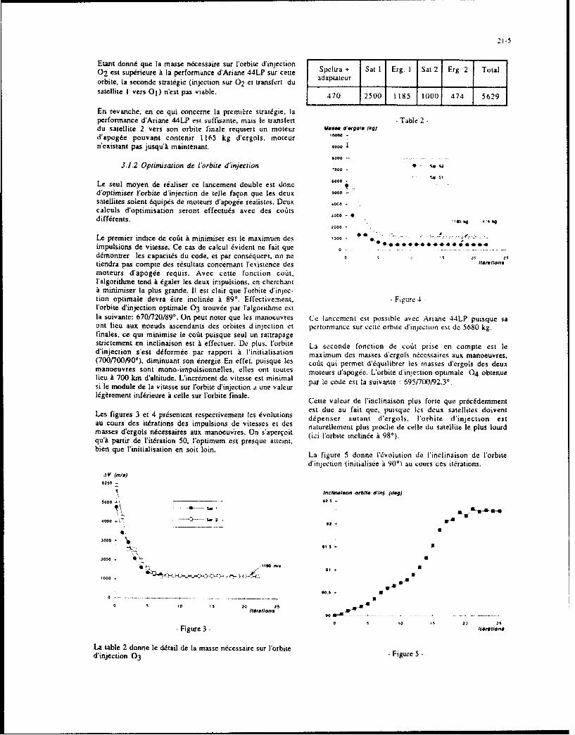
21-5
Etant donn6 que la masse nicessaire sur V'orbice d'injection + I Eg a02 est superieure a la performance d'Ariane 44LP sur eerie peya+ Sat I EgISa2 Erg. 2 Totalorbite. la seconde strategic (injection sur 02 et transfer[ du adaput~cursatellite 1 vers 01) n'est pas viable. 470 2500 1185 1000 474 5629
En reva~nche, en cc qui concerne la premi~re strat~gie, laperformance d'Aria~ne 44LP est suffisante, mats le transfert -Table 2diu satellite 2 vers son orbite finale requiert un maccur MaswW dff9Os fkg)d'apog~e pouvant contenir 1165 kg dcergols. moteur 00
n'existant pas jusqu'l matinteniant. 90
3.1 .2 Optimisation de b7orbite d~injection '0
6000Le seul mayen de ritliser ce lancement double est doned'optimiser Forbite d'injection de Iedle faqon que les deux Wsatellites soient dqui*~ de moteurs d'apogee realistes. Deux 4000
calculs d'optimisation seront effcctu.~s avec des co~ats 30
diff~rents. '
2-000
Le premier indice de cofit 1 minimiser est Ic maximum des 1o -*0****0**
impulsions de vitesse. Ce cas de calcul dvidcnt ne fait qucd~montrer les capacitds du code, cc par conscquer't, on netiendra pas compte des resultacs concerniant l'existence des I6alnmoceurs d'apogde requis. Avec cette fonction cout,l'algoritlime tend a 6galer les deux impulsions, en cherchant1 minimiser la plus grande. 11 est clair que lorbite d'injec-lion optimale devra Eire inclinde iL 89'. Effectivernent. -Figure4
l'orbite d'injection optimale 03 trouv~e par l'algorithme citla suivante: 670/720/89*. On pout noter que les manoeuvres Cc lanccmcnt cit possible avec Artane 44LP puusquc saoft lieu aux nocuds ascendants des orbites d'injection cc performance sur cctte orbite d'injection cit do 5680 kg.finales, ce qui minimaise le cofit puisque soul un rattrapagestrictement en inclinaison est i effectuer. Do plus, l'orbite La seconde fonction do cotat prise en compte est ledinjection s'est diforMde par rapport i l'initialisation maximum des masses d'ergols necessaires aix manoeuvres.(700/70,90), diminuant son energie En effet. puisque les cofit qui per-met d'iquilibrcr les masses d'ergols des deuxmanoeuvres sont mono -impul sionnelle s, dlles ont touds moteurs d'apogee. Lorbite d'inje'tion optimalc 04 obtenuelieu it 700 kmn d'altitude. L'incr~ment de vitesse cit minimal prI oeetl uvneý657O9.'si le module de la vitesse sir l'orbite d'injection a une valcur pa codcsIauint 69702..Itdg~rement inffrieure A celle sur lorbite finale. Cette valeur de l'inclinaison plus forte quo prt~ciddcment
Les igues et4 p~setcn resectvemnt es volcios ct due au fait quc, puisque les deux satellites doiventLes figures d es itrationse des ipulsions envtes ccS delUis d dpenser autant d'ergols. l'orbite d'injecCion estau cursdesitiatins es mpulion devitssc etdes naturellement plus proche de celle du satellite Ie plus lourdmasses d'ergols necessaires aix manoeuvres. On s'apcrqoi't (ici l'orbite inclino~e 198*).qu'I partir dc Ijitdration 50, l'optimum cit presque atteint,bien que l'initialisation en soit loin. La figure 5 donne idvolution de linclinaison de l'orbite
d'injectiin (initialis~c a 90') au cours Get iterations.'I V (mis)
6000-
Indinalsoe, orbit* d'ln. (deg)
30000 ~ 0
2000 - ----- s2@-
1000
200003
0 S 10 'S 20 25
0 ' '5 20 2S
- Figure 3 - 116,Itiont
La table 2 donne le d6tail de Ia masse necessaire sur l'orbite - Figure 5 -d'injection 03-

21-6
Les figures 6 et 7 montrent reSpeCtivemersr les 6volutions Dans le cas du lancement double. loptimisatior couplo~e dedes masses d'ergols et des impulsions; de vitesse. la trajcctoire de monide et des manoeuvre:ý a conduit it une
orbite d'injection qui pcimet de mettle 'a poste les deux
MaLSs. d'agols kq satellites avec des masses d'crgols rdalistes.
'0000 -3.2 Lancement d'une constellation
8000 -- Considdrons unc constellation de radiolocalisation (3)'000 - * 5 St compost~e dc trois satellites. de, 500 kg chacun. dont les
S. S2orbites finales ont pour 6ldments orbitauxa =42164 km
0000 e = 0,191 (hp =27733 km et h, =43840 km)
4000 i 18,34503000 -' w =254,887'
10500- "~.- ~~_ _- plus une diff~rcricc de nocuds ascendants de 1200 entreleo orbites.
0 5 10 520iforatlons Le lanceur UtiliSd POUr cc lancement triple est Ariane V,
6quipid de la coiffe courte (1870 kg) et du support externeSpeltra (900 kg). Les transferts sont de ty~pe bi-impul-
- Figure 6 - sionnel et ]a foniction cofit 'a minimiser est Ia somme desimpulsions de vitesses des trois manceuvres. Commeprecedemment. on consid~rcra tout d~abord une les transfents
'3V (na a partir d'une orbite d'injection fix~e qui scra Iibdt6e par Ia$000 suite afiro d'observer les amrdliorations apport~es par Ie
code. Enfin. dans les deux cas. une contrainte suppld-0000 - mentaire poun'a etrc activde afin d'assurer un bon equilibre
Sm i massique enire les satellites, La satisfaction de cctte4000>,. 2 contrainte moteur permet de limiter 'a 5%,' Idart entre les
masses d~ergols ndcessaires a chaque satellite et Icur valeur
300 moyenne.
2000 a 3.2.1 Orbile dinjertion fix&f
SL'orbite d'injection considerde est une GTO classique- * .. * * * inelinee ý 7* d'altitude pdrigdc 280 kmn ct d'apogee 'a 35786
kin d'aLtilude.
0 2 1 0 2 '4 Choisir unc orbite d'injection dcj'a inclinde 'a 18,3450 peut116rations sembler au premier abord plus intdresoant en terme de coat.
puisqu~il Tic resterait plus qu'un rattrapage de noeud
- iue7 -ascendant 'a effeetuer. N~anmoins, leo changements de- Figre -nocud ascendant entraineraient obligatoirement des
modifications d' inclinaison (sauf pour )c satellite dontA l'initialisation. Ico masses d'ergols niicessaires dtaient de l'orhite finale a le ms~me nocud ascendant que l'orbite9500 kg pour le satellite I et de 5650 kg pour le satellite 2. d'injection), cc qui conduirait ii un coiit trds important.Grice 'a l'optimisation de l'orbite d injection. ceo valcursont Wt considdrablement riduites pour arriver ka des masses Cette orbite GTO servira d'initialisation pour leorialistes (700 kg). optimisations suivantes.
La table 3 fournit le ddtail des diffdrentes masses our l'orbite Deux calculs ont dtd mends pour la misc 'a poste ii partir ded'injection 04, cette orbite d'injection. ]a contrainte moteur n'dtant activde
- - que dans on deuximcm temps. Bien entendo. le cofot cot plus
Speltra + Sat I Erg. 1 Sat 2 Erg. 2 Total important dans cc cas (707 dJs contre 6631 m/s).adaptateur La table 4 donne Ics r6c,ultats de l'optimisation dans le cas
- -. - - ou aucune contrainte nest imposce sur les masses d'ergols.II cot 'a noter quc leo valeurs des nocuds asc2ndants ne sont
470 12500 1700 1000 1700 15370 que relatives. En effet. Ic temps initial correspond arbi-
- - - - - trairCMcni au moment obt Y50 passe 'a Greenwich. Pourmodifier le nocud ascendant dc l'orbite d'injection. il ouffic
- Table 3 - done d'ajuster Ihleure tde tir.
La capacitd demport d'Ariane 44LP pour cette mission cotde 5512 kg.

21-7
Les masses d'ergols pour les trois satellites sont tr4sdiffirentes, Pour c&tter ces 6carts, on active la contxaince It#~ration 0 iteration 300
moteUrS. i injection ()7 13.8
p(o() AV (mis) Masse d'ergols Q injection (I)1O 147.3(kg) ________
_____________U - -(finaux () 9/129/249 28/1481268Orbite dinjection ISO - ________ _______
Orbtefial 1 133 41 A (m/s) 1833/2363/2435 1737/1355/2842
Masse d'ergols 414/588/614 385,280/773Orbite finiale 2 129 2363 588 (kg) II
coat (m/s) 6631 5934Orbite finale 3 249 2435 614 _______________ ______
-Table 6-- Table 4 -
Les figures 8 et 9 fournissent pius de ddtails sur lesLa table 5 resume les modifications induites par lactivation changements intervenus au cours des itdrations. Ellesde cette contrainte. prdsentent respectivensent les 6volutions des nocuds
____________ ascendlants et des inclinaisons des orbites d~injection.
C1 (o) A.V (m/s) Masse d'ergols nem iarstLal.
(kg)Afg. No~fud ASCandont (dog)
300
Orbite d'injection 180 - -
Orbite finale 1 9 2278 558200
Orbite finale 2 129 2355 585 0 W3
Orbite finale 3 249 2438 614 0S
-Table 5- 50- 0"___
Du fait que les masses d'ergols des deux derniers satellites 0---- - - -
6taient du mime ordre de grandeur. l'algorichnie n'a fait quc 50 s 00 '50s 200 250 3JC2
d~grader le cosit de la manoeuvre du premier satellite. iomln
3.2.2 Optimisation de Uorbite dinjection-Figure 8 -
SContrainte moteurs di~sactivde
Le point de d6part de V'optimisation est r~sum6 dans la table ft , 2--1-
4. En particulier. la somme des increments de vitc55 ocsise di Jn6cessaires aux transferts depuis une GTO 70 est de 6631 2Ssn/s. Aprý-s 300 itirations, elle est passie a 5934 m/s. et S~
i'inclinaison de lorbite d'injecction est passie i 13X8 et 2l'argument du nocud ascendant A 147,3*. De plus. Idnergiede lorbite a augmenti les altitudes de p~rig~e et d'apogeepeassant respectivement de 280 km A 611 kmn et de 35786 '
kmn 140586 kin.
On peut noter qu'au cours des it~rations. 1'6cart relatif des ...-- 1
noeuds ascendants des orbites finales demeure 6gal ý 1201. ' ~ *
cette contrainte restant satisfaite par la suite.
La table 6 compare les orbites entre l'initialisation et Ia 0 so 1o (0 so 2o 00 5z0 3*00convergence.
- Figure 9 -

Ces figures montrent qukl la convergence, les orbites I~rto 0 trto 0interm~diaire et finale du satellite 2 ant pratiquement m~me trio30 Iisin60
inclinaison et noeud ascendant, contrairement & l'ini-tialisatian. La figure 8 montre en particulier que ce noeud i injection ()13.8 6,4ascendant camrnun aux orbites interm~diaire et finale estaussi ccliii de jorbite d'injecuion. ce qui explique le faible il injection ()147.3 171.2cofit des manoeuvres effectu~es par le satellite 2. Letransfert est en fait quasi mono- impuIs ionnel (l14e S) fiaux () 28/1481268 -19/1001220impulsion: 1278 mi~s, 2nde impulsion: 77 mi's), la premi~er _________________
impulsion perinettant tin rattrapage global en 6nergie et en17/35/82 0527823inclinaison. AV (ru's) 17715282 09/7/23
Pour le satellite 1. on constate une dvolution relativement Masse ergols (kg) 3 85/280/773 496/524/549minimne des orbites finale et intermidiaire entre -les rit~drations 0 et 300. aussi biers en terme de noetid ascendant Coait (mis) 5934 6526que d'inclinaison. Comme pour le satellite 2. le transfert eStquasiment mono-impulsionnel (1Ure impulsion; 1662 mIs,-Tal7-2nde imupulsion: 75 m/s).Tal7
Enfin. les dcarts en inclinaison et en noeud ascendant entre La figure I I donne les Avolutions des masses d'ergols deles orbite d'injection. interm~diaire et finale du satellite 3 ehaque satellite au cours des iterations.ont sensiblement augment6 au cours des it~rations. Pa On note que seules 50 it~rations sont n~cessaires it laconsdquent, cc transfert est beaucoup plus cofiteux que les satisfaction de la contrainte moteurs. Ics masses d'ergolsdeux autres (773 kg d'ergols requis contre 385 et 280 kg requises gardant quasiment les rn~mcs valeurs par la suite.pour les satellites I et 2). L'volution des masses d'ergolsest illustrde sur la figure 10. On observe la diminution des PASS. c-Ergois (kg)masses d'ergols dui satellite 2 permettant une aimdlioration $00du cofit, ainsi que la d~gradation de la manoeuvre dui satellite
Amas". dergolS (kg)Soo 40
700oo 303 ________
600 200 so- ____ so____ I___
SOO~1003
00* 300 320 340 360 35. 400 420 404 414 904
200 +
100 -Figure I1-
0 -----.- _________--------
50 00 50 00 250£grations Les figures 12 et 13 d&crivent respectivement les
dvolutions des noeuds ascendants et des inclinaisons desorbites d'injection, intermddiaires ct finales.
- Figure 10 -
* Cotraice mccur actv~eArg. Notud Ascondant (dog)Containe mocur actvde400
Les risultats pr~c~dents montrent une sensible diminution vwwwwunm- --- 4- 0 IM,
du cofit global, mais au d~triment de 1Edquilibre entre IeS 300 -*-0
masses dcergols des diff~rents satellites. Pour assurer la 0 f.2 isym~ftrie de ]a constellation, i partir de l'itdration 300, tine 2so -6fs~rie de 300 it~rations suppl~mentaires a it6 effectude en 0* ft Ie~** ------ ( I
activ ant la contrainte moteurs. zoo--.-. 0 M42
La table 7 compare Ics rdsultats des deux convergences0suivant que la contrainte moteurs est active oti non. Comme 'o **4----.- 94
on pouvait le privoir. le respect de cette contrainte entraine Stine augmentation du cofit total. Cette valeur obtenue est hcomparer Ia avec celle correspondant au cas de lorbite 0 ----------.-------d'injection fix~e i tine GTO 70, contrainte moteur active 300 350 400 450 So(§3.2.1), ofi I'on constate une nette am~lioration, Ie cofit 1ai
passant de 7071 mis i 6526 in/s.- Figure 12 -
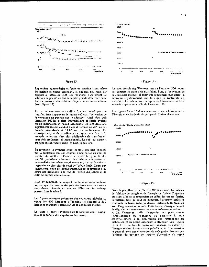
*.1 -~-~-- o --- '---~-- 03 IV towa (Mis)
lcIni1f Col rd~j)as- 7000 -
18,345**,a
- -L~.'.-'-'- - -0000-
4000 -
10 ~3000
300 350 400 aso So0 0 --
i4rtdfions 0 GOo 2120 300 .00 IOU 600l1olmdlons
- Figure 13 - - Figure 14 -
Les arbites interm~djaire et finale du satellite I ant m~me Ue coait ddcroit regulicrement jusquki l'it~ration 300. tautesinclinaisan et nocud ascendant.. et ant tr~s peu vari6 par les conltraintes etant do~jý sarisfaices. Puis. i l'activation derapport it l'itdration 300. En revanche, l'incrdment de la contrainte moteurs. il augmente rapidcment puis delcrokitvitesse a augmen6d du fait de la plus grande diffdrence entre nouveau rcguliicrcment une fois que la contraince eatles inclinaisans des arbites d'injection et intermeddaire satisfaite. La valeur trouvee apres 600 itdrations est. bien(vair Figure 13). cntcndu supericure io celle de Yitidrauon 00.
En cc qui concemne le satellite 2, 6tant donnt~i que son Les figures 15 et 16 donnent respectivement 1l6volution detransfert 6tait auparavant le mains cotiteux, l'activation de l.nergicet de I'altitude de perigee de l'orbite d'injectian.la cantrainte ne pauvait que le ddgrader. Ainsi, alors qu iili tiration 300 les orbites intermediaire et finale avaicntmime inclinaison et nocud ascendant, les 300 ittirations ngldoiCbtdioco k)supplimentaires ont conduit i une diffirence de 72' sur les nr.deabl dicto(i)
noeuds ascendants et 12.80 sur les inclinaisans. Enconsiquence, et de maniere i Tattrapper ces 6carts. la 2SOO*0 *Ug.U44g
seconde impulsion Tnest plus n~gligeable (le transfert cot 200*
CCEte faiS reellement bi-impulsiannel). Lc coati du transfertest donc micux re~parti entre les deux impulsions. 20000
En revanche. la symi~trie entre les trais satellites impas~e 15000par la cantrainte mateurs canduit 1 une baisse du coat detransfert du satellite 3. Comme le mantre la figure 12. &is 10000 A0U .1
lea 50 premieres itdrations, les orbites d'injectian etinterrnidiaire ant mime noeud ascendant, qui par la suite se $0000rapproche de plus plus de celui de Vaorbite finale. Quant auxinclinaisans, celle de lor1bite interni~diaire se rapproche. au 0~ -----. . -
cours des itdratians. it la fais de l'orbice d'injectian ct dc a 100 200 IO0 .00 S00 600
celle de l'orbite intermddiaire. It~,ations
Bien evidemment, le respect de la cantrainte mateura iue1impose que les masses d'ergals des trais satellites soient-Fiue1sensiblement identiques, camme l'illustrent les valcurs Dn apein ai d t30i~ain) e aerparties dans la table 7. asl rm e ate(e0130idton)lsvaus
de l'aluitude de perigtee et de lNnergic de larbite d'injectiancroissent afin de se rappracher de celles des orbites finales,
Lea figures suivantes pr~sentent des dvalutians glabalcs au permettant ainsi au coait de dirninuer. Loraquaon active lacours des 600 itdrations effectudes. Ie raccard 4 300 cantrainte moteurs, Id6nergie dccroit fartcment. en parallileitdratians marquant l'activation de la cantrainte mazeurs. avcc l'augmentatian du coAit. Cctte baisse d'6ncrgie permet
dc ddgradcr lea manocuvres lea mains caiiteuscs (satellites ILa figure 14 ddcrit l'dvolutian de la fonictian coait (ccstaý- et 2). Cependant. cdie necmpeche pas pour autantdire de la samme des impulsians de vitesse). l'amdlioratian du transfert du satellite 3. due
essentiellement it Ia diminution des rattrapages eninclinaisan et en nacud ascendant ii effectuer (vair figures12 et 13). Une fois la cantrainte satisfaite. la valeur derd6nergie revient a san niveau prdcddent. et laoptimisationSe pourSUit avec une diminutian du coat glabal. Natans quel'altitude du pdrigde de l'orbite d'injection n'a cease

21-10
d'augmenter au cours des iterations, I'avorisant ainst une Pour le lancement de la constellation, on a pu gagner. gricebaisse du coit, au ddtriment de la masse totale de charge a loptimisation, entre 7 et 10% par rapport i la mise kutile plac~e sur cette orbite. poste deputs une GTO 70 classique.
Alt. doe P~rtgo de )Orbit* d'Inj. (kmJ Gricce a b, diversite des contraintes -facilement activables-,00, et aux nombreuses fonctions coots, un grand nombre de cas
-0 sign peuvent Etre traitds par le programme. Llintdrit de cettemthode d'optimisation repose sur le fait qu'elle peut grer
S00 .n un grand nombre de parametres (particuh&ement dans le cas
700- des manoeuvres bi-impulsionnelles), dvitant ainsi un
800 - ,0wau *" balayage fastidieux de toutes ]es combinaisons possibles.
400 •
4000-•"•:• Aclivallor 0* 0• cono~ain:. 1004UfS
300
200
00 -- REF RENCE
0 ,00 200 300 400 Soo1]30 C. Aumasson, Ph. Landiech: "MWthode itdrative deIt4retions type gradient projete gencralise pour loptimisation
parametrique et fonctionnelle de sys imes- Figure 16 - dynamiques soumis a des contratntes.'
N.T. 1988-9 ONERA
4 CONCLUSION [2] Ph. Landiech. C. Aumasson: "Mont&e optimale dulanceur Ariane V-L5 avec contrainte de retomboe du
Ces deux exemples ont montre l'intdr&t d'optimiser de faqon premier 6tage."couplie la montie et les manoeuvrcs dans le cas de R.T. n' 21/6115 SY - ONERA 1986lancements multiples.
13] H.Barangcr, J. Bouchard. T. Michal: "Syst~me deDans le cas du lancement double, l'optimisation a permis navigation par satellites ii couverture europdenne."d'effectuer la mise A poste de deux satellites d'observation au Cor~mmunication AGARD 1992, Bruxelles Sessionmoyen de moteurs d'apogde rdalistes. WI: TacSat applications- Systems
Discussion
Question: My question concerns the equivalence constraintyou use in order to limit to 5% the gap between eachsatellite propellant mass and their average value.Is it possible to minimize the maximum value of thepropellant masses instead of activating this constraint?
Reply: The cost index (i.e., minimizing the maximumof the propellant masses) may be considered as itis presented in the paper, and could have been usedin this case instead of trying to minimize the criterion(sum of the delta v) while activating the equivalenceconstraint. Never the less, the 5% margin allows arespective balance between the three satellite masseswithout making them exactly equal (which might betoo strong a constraint in this complex system wherethe launcher ascent phase and three bi-pulse maneuversare simultaneously optimized).
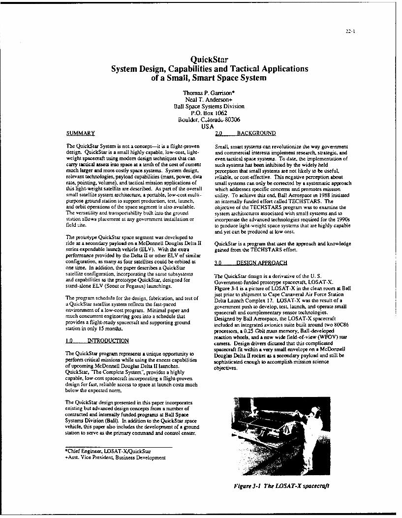
2-21
QuickStarSystem Design, Capabilities and Tactical Applications
of a Small, Smart Space System
Thomas P. Garrison*Neal T. Anderson+
Ball Space Systems DivisionP.O. Box 1062
Boulder, C.loradu 80306USA
SUMMARY 2.0 BACKGROUND
The QuickStar System is not a concept-it is a flight-proven Small, smart systems can revolutionize the way governmentdesign. QuickStar is a small highly capable, low-cost, light- and commercial interests implement research. strategic, andweight spacecraft using modem design techniques that can even tactical space systems. To date. the implementation ofcarry tactical assets into space at a tenth of the cost of currant such systems has been inhibited by the widely heldmuch larger and more costly space systems. System design, perception that small systems are not likely to be useful,relevant technologies, payload capabilities (mass, power, data reliable, or cost-effective. This negative perception aboutrate, pointing, volume), and tactical mission applications of small systems can only be corrected by a systematic approachthis light-weight satellite are described. As part of the overall which addresses specific concerns and promotes missionsmall satellite system architecture, a portable, low-cost multi- utility. To achieve this end, Ball Aerospace in 1988 initiatedpurpose ground station to support production, test, launch, an internally funded effort called TECHSTARS. Theand orbit operations of the space segment is also available, objective of the TECHSTARS program was to examine theThe versatility and transportability built into the ground system architectures associated with small systems and tostation allows placement at any government installation or incorporate the advanced technologies required for the 1990sfield site. to produce light-weight space systems that are highly capable
and yet can be produced at low cost.The prototype QuickStar space segment was developed toride as a secondary payload on a McDonnell Douglas Delta I1 QuickStar is a program that uses the approach and knowledgeseries expendable launch vehicle (ELV). With the extra gained from the TECHSTARS effort.performance provided by the Delta 11 or other ELV of similarconfiguration, as many as four satellites could be orbited at 3.0 DESIGN APPROACHone time. In addition, the paper describes a QuickStarsatellite configuration, incorporating the same subsystems The QuickStar design is a derivative of the U. S.and capabilities as the prototype QuickStar. designed for Government-funded prototype spacecraft. LOSAT-X.stand-alone ELV (Scout or Pegasus) launchings. Figure 3-1 is a picture of LOSAT-X in the clean room at Ball
just prior to shipment to Cape Canaveral Air Force StationThe program schedule for the design, fabrication- and test of Delta Launch Complex 17. LOSAT-X was the result of aa QuickSrar satellite system reflects the fast-paced government push to develop, test. launch, and operate smallenvironment of a low-cost program. Minimal paper and spacecraft and complementary sensor technologies.much concurrent engineering goes into a schedule that Designed by Ball Aerospace, the LOSAT-X spacecraftprovides a flight-ready spacecraft and supporting ground included an integrated avionics suite built around two 80C86station in only 15 months, processors, a 0.25-Gbit mass memory, Ball-developed
reaction wheels, and a new wide field-of-view (WFOV) star1.0 INTRODUCTION. camera. Design drivers dictated that this complicated
spacecraft fit within a very small envelope on a McDonnellThe QuickStar program represents a unique opportunity to Douglas Delta I1 rocket as a secondary payload and still beperform critical missions while using the excess capabilities sophisticated enough to accomplish mission scienceof upcoming McDonnell Douglas Delta [I launches, objectives.QuickStar, '"he Complete System". provides a highlycapable, low-cost spacecraft incorporating a flight-provendesign for fast, reliable access to space at launch costs muchbelow the expected norm,
The QuickStar design presented in this paper incorporatesexisting but advanced design concepts from a number ofcontracted and internally funded programs at Ball SpaceSystems Division (Ball). In addition to the QuickStar spacevehicle, this paper also includes the development of a groundstation to serve as the primary command and control center.
*Chief Engineer. LOSAT-X/QuickStar Q+Asst. Vice President. Business Development
Figure 3-1 The LOSAT-X spacecraft

22-2
4.0 LAUNCH SYSTEM OVERVIEW Spacecraft equipment is mounted inside of the spacecraft orattached to the exterior structure within the envelope
As with the case of LOSAT-X. QuickStar is launched as a provided (Figure 4-1). Equipment attached to the spacecraftsecondary payload on a Delta 11. The secondary payload exterior includes three avionics modules, three solar arrayconcept is shown in Figure 4-1. The QuickStar spacecraft is panels, reaction wheels, torque rods. two patch antenna sets,attached to the Delta second stage through a payload adapter trickle charge and test connectors, and a separationsystem positioned between the second stage guidance section fitting/connector. Internal equipment includes aand the vehicle fairing, well outside and below the primary communication transponder, gyro. battery, and payload.payload envelope. Depending on the excess launch Figures 5-4 and 5-5 illustrate both internal and externalcapability of the particular Delta/ 1launch, up to four component general arrangements.QuickStars could be carried into space on a single launch.The merit of not requiring a dedicated launch substantially Structure/Mechanisms Subsystemtodu.4 i;tc'h %.obts and providca niv,, iawuio.ii oppurwki~i...to the user. However. if required. QuickStar is easily The QuickStar spacecraft structure is approximately 49adaptable to other launch vehicles because of its small size inches long by 36 inches wide and 12 inches deep. The upperand light weight. deck doubles as solar panel substrates and is covered with
solar cells providing approximately 12 square feet of solar5,0 SPACECRAFI SYSTEM array area on three panels. The lower deck assembly
provides mounting surfaces for all electronics boxes andQuickStar is a free-flyer. Design life is six mondts with a gcal pacecraft components. The upper and lower decks armof up to one year. QuickStar is a small highly capable. iow- connected by four yoke assemblies forming the spacecraftcost, light-weight satellite system using modern design bus enclosure.techniques. The QuickStar spacecraft is a 3-axis stabilizedvehicle that uses three reaction wheel assemblies, three A separation attach fitting is externally mounted on the lowermagnetic torque rods, a star tracker, and a .,-axis gyro deck. The attach fitting mates with the launch vehiclepackage to maintain attitude control and determination. separation mechanism. Separation mechanisms and ordnanceFigure 5-1 is a system concept summary and illustration of consisting of four arrayed explosive bolt/spring assemnliesthe QuickStar spacecraft. The QuickStar satellite are provided on the launch vehicle side of the separationperformance exceeds typical small satellite capabilities interface.(Figure 5-2).
Theirmal SubsystemA functional block diagram of the QuickStar flight systemshown in Figure 5-3 illustrates the extent that the spacecraft The thermal subsystem provides the capability to maintain allis under software control. Through the use of an integrated spacecraft components to within prescribed temperaturecentral processor, as compared to most satellite systems that limits. Thermal control is accomplished by passive meansare a combination of dedicated hardware control units and using high emissivity/low absorptivity finishes, and thermalsoftware processors, QuickStar is able to improve reliability isolating hardware. The spacecraft design does not requireby replacing hardware with software at the same time the use of multi-layer insulation blankets, louvers and/orreducing volume, power, and weight requirements. In active heaters. Telemetry provides temperatureaddition, with the integrated central processor, extensive measurements from thermistors located near or on varioustesting of all spacecraft systems and control modes is possible key components and payload equipment.on the ground providing the confidence that it will functionthe same way on orbit.
TUd STA
I I PAM........ .
S - t~g.tJtot
S~Mc~onnell Ocuglas Clelta •aun.ci• VehiclO with OPS SpaceciatliOu'ckStar'
Figure 4-1 Integration of QuickStar to the Delta 11 Launch Vehicle

22-3
GENERAL ARRANGEMENT KEY FEATURES
"* Delta 11 compatible
"* Spacecraft Mass =150.0 Ibm (68.2 kg)
"* PayloadMass =70.0 Ibm (31.8 kg)Volume - 1.7 ft'(0.05 in
3)7 Extended Vol. = 0.8 ft'(O.02 m)
- 3-axis stabilization
"* Power- 130 W (average)- 214 W (peak)
"* SGILS compatible communication links- U~plink I Kbps- Downlink
- Payload: 1.0 Mbps- Spacecraft: 1.6 or 32 Kbps
- Encrypted links, if required
"* Integrated avionics
"* Passive thermal control L 1
Figure 5-1 QuickStar spacecraft system concept
CHRCEITC USUAL SMALLSAT QUICKSTAR COMMENTSCHAACTRISICLIMITATIONS CAPABILITIES
Prime structure Custom structure Honeycomb decking/ inexpensive and simpletrusawork box to build.
Polnting/stabillzation Inertial spinner or All-pointer (3-axis) Controlled by threegravity gradient 1 N-in-a reaction wheels.
Pointing conirol 1-3 deg 0.1 dog
Attitude knowledge 0.25 dog 40.1 dog
Slew rates No capability 5 deg/sec (3-axIs) 10 deg/sac maximum.
Peak Power <100 watts 214 watts GaAs solar arrays.
On-board processing 500 KIPS 2 MIPS 80386 processor
Data storage 100 Mblts 1 -2.5 Gbits Solid state memory.
Down:Ink data rate 32 KbIts/sec 1 -5 MbIts/sec All links encrypted, If req'd.
Propulsion Rarely considered or Available. AV . 200-300 ft/sac.
available as an option.
Figure 5.2 QuickStar key subsystem capabilities

22-4
-I PAYLOAD jA* Po
iLaw
~ PawTranun*
Attitude, Telemetry & Command oft IosvIJcVW~IProcessor (ATCP) - N
Power Lawe
PowerPoe
a.U0 T Oh6 C
Pow.,rry Spumo
LS 001
Figure 5.3 QuickStar spacecraft functional description
Battery (2) - Trnansmtter 1 ' Buffer Box-Sun Sensor, Pitch
dE ~ - Star Camera
AftMarienas (2)
- PAYLOAD VOLUME
Sun Sensor, Roll Gyro______
Aeseeiver -h / j Propubun Elec: (Optional)
Figure 5-4 QuIckStar internal component general arrangement

22-5
Whee Driver Elee - Tea Connectom -• - Mma Memory
I W
1Hydilaine Tank , :2..• ,.Thrutner (Optional) -___'r•:I•
..- -- - . - ep o , (4)
Torque Rods (3) --. POu - PocesorReaction Wheels (3) -
Figure 5-5 QuickStar external component general arrangement
Electrical Power Subsystem In keeping with the concept of integrated avionics, QuickStarhas replaced the separate boxes for each major on -board
The electrical power subsystem provides electrical bus power function (i.e.. command and data handling, atut-tdeto energize spacecraft loads in all phases of the orbit. It determination and ccrrol, and telemetry, track, and control)provides regulated power to the payload, power switching for each typically with its own power supply, packaging.non-essential components, and undervoltage and overcurrent connectors, and cable harness with a 80386 central processor.protection for the spacecraft bus. The QuickStar spacecraft memory, and architecture technologies.uses a GaAs solar array for power collection and a battery forenergy storage. The electrical power subsystem consists of The attitude, telemetry, and command processor (ACTP) 1/0three solar panels, a 6 Amp-hour NiCd battery (or an optional provides for 32 analog inputs and 4 outputs. 32 parallel inputs12 Amp-hour battery), dclde converters, charge control and and 32 outputs. 4 serial inputs and 4 outputs, and 32 relaypower switching relays. The power subsystem operates at a driver outputs. The special functions interface contains anominal 28 volt dc. The system is designed to provide an serial I/O DMA controller, torque rod drivers, sun sensoraverage of 130 watts to the spacecraft system inoluding a 15- preamplifiers, momentum wheel tachometers, transponderwatt reserve, interface, and real-time clock circuits. The memory devices,
built with CMOS technology, are packaged using state-of-Bus undervoltage levels ("yellow" and "red") are ground the-art memory module manufacturing techniques, mountedselectable. When bus voltage drops below the "yellow", non- to four printed circuit wiring boards using surface mountessential components are switched off including the payload, technologies, and architected into the avionics suite withmass memory, and spacecraft transmitter. The receiver, error detection and correction circuitry. The result is aflight processor, gyro, PDU, reaction wheels and drivers are processor box that can recover from single event upsetsmaintained on the essential bus. In the event of a "red" (SEUs), is iatchup free, and can tolerate high radiation levels.undervoltage, only the spacecraft flight processor, powerdistribution unit, and receiver are left powered. This Command. Telemetry, and Ranging (C.T&R) Subsystemconfiguration is sufficient to safe the spacecraft until a plan isgenerated by the satellite operations crews to analyze the The CT&R subsystem provides for the communicationanomaly and command disconnected equipment back on. between the spacecraft and the ground-based stations inProtection is also provided should an overcurrent condition addition to providing an interface with all spacecraftoccur. Components on the non-essential bus are switched off subsystems. Omnidirectional uplink capability is provided bysimilarly to the bus undervoltage situation, the fore and aft L-band patch antenna sets. a communications
transponder, and the spacecraft attitude, telemetry andAvionic command processor (ATCP). The command uplink rate is 1
to 2 Kbps. Downlink capability is provided by the ATCP.The concept of an integrated avionics suite is borrowed from data memory assembly (DMA), transponder. and fore and aftcurrent developments for fighter aircraft where all the S-band patch antennas. Downlink rates include I Mbps formonitoring, control, housekeeping, and processing functions the payload data and real time 1.6/32 Kbps for spacecraftare integrated together, not only for the synergistic effct, but health and status.also to reduce cost and improve reliability andmaintainability.
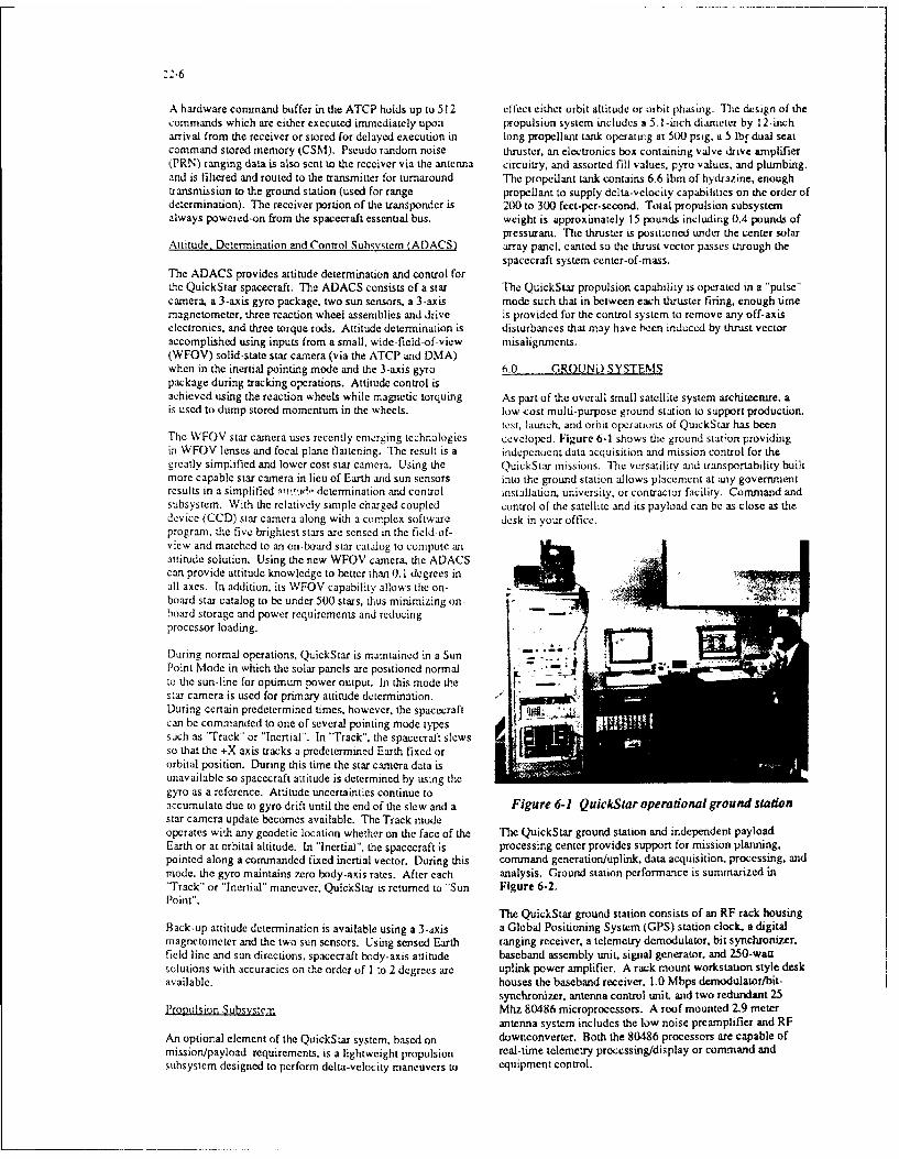
22-6
A hardware command buffer in the ATCP holds up to 512 effect either orbit altitude or orbit phasing. TMe design of thecommands which are either executed immediately upon propulsion system includes a 5. l-inch diameter by 12-incharrival from the receiver or stored for delayed execution in long propellant tank operatuig at 5X) psig, a 5 lbf dual seatcommand stored memory (CSM). Pseudo random noise thruster, an electronics box containing valve drive amrtplifier,PRN) ranging data is also sent to the receiver via the antenna circuitry, and assorted fill values, pyro values, and plumbing.and is filtered and routed to the transmitter for turnaround The propellant tank contains 6.6 Ibm of hydrazine, enoughtransmission to the ground station (used for range propellant to supply delta-velocity capabilities on the order ofdetermination). The receiver portion of the transponder is 200 to 300 feet-per-second. Total propulsion subsystemalways poweied-on from the spacecraft essential bus. weight is approximately 15 pounds including 0.4 pounds of
pressurant. The thruster is positioned under the center solarAttitude, Determination and Control Subsystem (ADACS) array panel, canted so the thrust vector passes through the
spacecraft system center-of-mass.The ADACS provides attitude determination and control forthe QuickStar spacecraft. The ADACS consists of a star The QuickStar propulsion capability is operated in a "pulse"camera, a 3-axis gyro package, two sun sensors, a 3-axis mode such that in between each thruster firing, enough timemagnetometer, three reaction wheel assemblies and drive is provided for the control system to remove any off-axiselectronics, and three torque rods. Attitude determinaLion is disturbances that may have ,een induced by thrust vectoraccomplished using inputs from a small, wide-field-of-view misalignments.(WFOV) solid-state star camera (via the ATCP and DMA)when in the inertial pointing mode and the 3-axis gyro 6.0 GROUND SYSTEMSpackage during tracking operations. Attitude control isachieved using the reaction wheels while magnetic torquing As part of the overall small satellite system architecture, ais used to dump stored momentum in the wheels. low-cost multi-purpose ground station to support production.
test, launch, and orbit operations of QuickStar has beenThe WFOV star camera uses recently emerging technologies developed. Figure 6-1 shows the ground station providingin WFOV lenses and focal plane flattening. The result is a indepenuent data acquisition and mission control for thegreatly simplified and lower cost star camera. Using the QuickStar missions. The versatility and transportability builtmore capable star camera in lieu of Earth and sun sensors into the ground station allows placement at any governmentresults in a simplified •:i'ud, determination and control installation, university, or contractor facility. Command andsubsystem. With the relatively simple charged coupled control of the satellite and its payload can be as close as thedevice (CCD) star camera along with a complex software desk in your office.program, the five brightest stars are sensed in the field-of-view and matched to an on-board star catalog to compute anattitude solution. Using the new WFOV camera. the ADACScan provide attitude knowledge to better than 0.1 degrees inall axes. In addition, its WFOV capability allows the on--board star catalog to be under 500 stars, thus minimizing on-hoard storage and power requirements and reducingprocessor loading.
During normal operations, QuickStar is maintained in a Sun - aPoint Mode in which the solar panels are positioned normal " •-to the sun-line for optimum power output. In this mode the .star camera is used for primary attitude determination. -ADuring certain predetermined times, however, the spacecraft _can be commanded to one of several pointing mode typessuch as "Track" or "Inertial". In "Track". the spacecralt slewsso that the +X axis tracks a predetermined Earth fixed ororbital position. During this time the star camera data isunavailable so spacecraft attitude is determined by using thegyro as a reference. Attitude uncertainties continue toaccumulate due to gyro drift until the end of the slew and a Figure 6-1 QuickStar operational ground stationstar camera update becomes available. The Track modeoperates with any geodetic location whether on the face of the The QuickStar ground station and independent payloadEarth or at orbital altitude. In "Inertial", the spacecraft is processing center provides support for mission planning,pointed along a commanded fixed inertial vector. During this command generation/uplink. data acquisition. processing, andmode, the gyro maintains zero body-axis rates. After each analysis. Ground station performance is summarized in"Track" or "Inertial" maneuver, QuickStar is returned to "Sun Figure 6-2.Point".
The QuickStar ground station consists of an RF rack housingBack-up attitude determination is available using a 3-axis a Global Positioning System (GPS) station clock, a digitalmagnetometer and the two sun sensors. Using sensed Earth ranging receiver, a telemetry demodulator, bit synchronizer,field line and sun directions, spacecraft body-axis attitude baseband assembly unit, signal generator. and 250-wattsolutions with accuracies on the order of I to 2 degrees are uplink power amplifier. A rack mount workstation style deskavailable. houses the baseband receiver, 1.0 Mbps demodulator/bit-
synchronizer, antenna control unit, and two redundant 25Propulsion Subsystem Mhz 80486 microprocessors. A roof mounted 2.9 meter
antenna system includes the low noise preamplifier and RFAn optional element of the QuickStar system, based on downconverter. Both the 80486 processors are capable ofmissionlpayload requirements, is a lightweight propulsion real-time telemetry processing/display or command andsubsystem designed to perform delta-velocity maneuvers to equipment control.

PARAMIETIER GROUND STATION The complete workstation incorporases additonjal 80486PERFORMANCE microprocessors and off-the-shelf equipment in a distributed
processin; environment providing mission planning and orbitTelemetiry Acquisition deternination support. as well as off-line data processing and
-Frequenc~y SGLS. STON a2, OdSN cirarneli analysis. Ground stations processors are networked viaMoNdulator. Types PM. 8PSK, OPSi( (NRZ L.N.S) Ethernet links and are separately connected to the incomingDOata Rates. 1 .5 Mbps. t.6 32 Kbps
*Unk Margin *3,2 c18, 1 Mbps @5" Elevation telemetry data and command lines via RS-422 high speedCom~wdL~iik 14.8 d8. 32 Ktipg @j V Elevation serial interface boards. Each works tation is provided with a
Comn FeUp~ink~aim ulSL oerg 16 o14 ~) printer for local Control of telemetry snaps, systemn messages.NASA STONIDSN (20251to 2120 NI-i) and status printouts. All incoming telemetry data are
-Cmii Rate 1, . zA 10 Kbps archived redundantly on digital 2.3 Gbyte: 8-mm, tape drives.*Ternary Cmrd Uplink SGLS CTOR-50) or STON nompautiba Telemetry data is first buffered in ground processor memory*Unk Margin -IS.1 B(250 W Upinkr4 Tran~smitter) and then subsequently stored off to either disk or tape.
Ranging A, SGLS (TOR-59i of STON compatubleOr*Deaiinto 1.0 Km ofetr r(Otcitia~Ng As backup, QuickStar can provide its own Mission Unique
Antenna System Equipment (MUE) in the Consolidated Space Test Center*Gain -34 OBI(9.5 toot deia) (CSTC) of the Air Force Satellite Control Network (AFSCN)-ownoeloT / 7 ~ *lId0K z much like Delta Star and LOSAT-X (F.,:Ure 6-3). Data from*Poiraing Capability -Az - 0to 360W the spacecraft is seilyrue hog h S oCT
E6-O01 180" NIUE where it is put on tape (still encrypted) and routed toAccuracy . 0,5 to Track the Quick Sar ground station for processing and review.
Operations iIntrace* STOL Syntax Duplicated The AF'CCN can suppori QuickStar missions through the*RTntm Displays *User Defiriable Tabuiar)Graohics DsolayCnsldedSaeTtCnerCS )adiswodwd*Tim Urmits Checks Data Base Definabie Raw Tim unirs ChxCnoiatdSaeTetCneiWT)adit olwdOpDerator Alerf Mg *Providedfor Lmits, Cmd 6 system Eror netwo~rk of Remote Tracking Stations (RTS). This has theData Caotiieilauality *Frame Sync. Mafor a Minor Frame Courti benef it of providing QuickS tar missions l,% ih satellite
-Printoul Catiatlility Provided by Operator or Procedure Call-rimn Simulator Ma~or. Minor Frame, Suocom & FiSd 7nm command and data coverage at selected passes on a 24-hourCmd Echo Validation Ternary Cme Turnaround & S/C rim EcnD pCr day basis A 9600 bps modem interface provides
communication to and from the mission unique equipment
Figure 6-2 Ground station and control center (MUE) in the CSTC enviromrstent and also remote telemetryperfomancedisplay capability to other non-colocatled PCs. The MUE and
software are ideitiucal to the comnmand and control system
QuickStar
sitsi RTS
"iRTS
sitIRTS
iRS
AFSCNTracking& ats USERSupport GROUND STATtON
L . H.IftCse,. CSTCNOF
*s C. cAA
Figure 6-3 QuickStor ground system provides worldwide AFSCN S(;IS coverage

22-8
used in the QuickStar ground station. The MUE receives alltelemetry data from DSM via an RS-422 serial interface. Di- CUCKSTARbit commands are generated in the MUE for throughput to the CARAC RIS CADILMESRTS network. The overall MUE approach was selected topreclude having to develop DSM related software, command.and telemetry da:a bases. Although, the approach still allows Pointing stabilization All-pointer (3-exls)use of standard DSM services for network control, data Pointing control 0.1 deginterfaces, tracking, and orbit determination.
Attitude knowledge -c0.1 degOrbit determination is performed at the QuickStar groundstation. At the ground station. digital ranging data (without Slow ratee 5 dee/sec (3-axis)range rate) is collected and a single site solution is generated Payload power 40 W (orbit &ve.)using the Microcosm 80386 based orbit determination Payload data rate 4 Mbyte/secsystem. Payload weight
70 Ibm
7.0 TACTICAIIPAYLOAD APPLICATIONS Payload volume 1.7 cubic feet
The QuickStar configuration is tailored for small payloads of Optional volume 0.8 cubic feetvarious configurations and its subsystems provide impressive On-board processing 2 MIPScapabilities to the tactical payload (Figure 7-1). Although Data storage 1 GbitQuickStar offers an optional propulsion zapability, the weightof adding the propulsion system reduces the payload Downlink data rate 1 MbIts/seccapability by approximately 15 pounds.
The QuickStar payload cavity has a volume of 1.7 cubic feet.The volume consists of three nearly equal cubes as shown in Figure 7-1 QuickStar payload capabilitiesFigure 7-2. The bulkheads forming the cubes can bepenetrated to form a single volume to accommodate larger Small. smart systems can contribute to many tactical supportinstruments. In addition. 0.8 cubic feet of volume, located in missions in ways that are only beginning to be understood.front of the forward bulkhead, is also available for Before these systems can become an integral part of the forceinstruments longer than the payload cavity. However, the use structure, convincing mission analyses and utility assessmentof this volume is contingent on the particular primary payload must be performed. A number of potential tacticalbeing flown on the Delta 11 and must be negotiated on a case applications for a small, smart space system are identifiedby case basis, such as Earth observations/remote sensing, surveillance,
communications, and technology demonstrations.The capability to penetrate the bulkheads of the payloadcavity allows a wide variety of instrument configurations to Battlefield Surveillancebe integrated into the QuickStar. Various "real" instrumentconfigurations being installed into the spacecraft are shown in Tactical commanders need to reliably and accurtrz!y detect,Figure 7-3. Section A of the figure shows several small characterize, and target enemy forces. Advancing armor.instruments being integrated into the payload cavity, with surface-to-air (SAM) sites. airfields, supply depots,aperture penetrations for each sensor through either the headquarters units, etc., all need to be located and delt with.forward bulkhead or through the solar array substrait. A wide variety of battlefield conditions need to be monitored.Section B shows how the internal bulkheads are penetrated toaccept a long. small diameter instrument. Section C&D showother instrument and electronic module configurations thatalso can be integrated into the QuickStar.
Negotiable Apertures(Also Opposite)
Bulkhead(3 Places) •<
Negotiable External
Extenson (Delta-,l .220 (01T. "214"84)Primary-Payload diaDependent) , .,
', / : --.- i='. .. /7 3 :• •. 236( 9 3),- 31 ý2) 4 '
"". L -. ." I -.42 (10.05,).
25,4 02 u.0) 2 .a (9lu )
Figure 7-2 QuickS far payload volume

22-9
Protonelectron, solar cosrnic my andgalactic X-ray sensors Surveillance Sensor
RF Payload Multi-Spectral Earth Observation Sensor
Figure 7-3 Four possible payloads that are compatible with QuickStar
Figure 7-4 depicts a smalL smart space system carrying an Tactical Sirnal Collectionclectro-optical sensor. Reasonable size sensors at altitudes of300 to 500 km can sweep selected regions of a battlefield Battlefield RF signal collection is similar to battlefieldwith ground resolution of between 1.5 to 3.0 meters electro-optical surveillance: the payoff to the tacticaldepending upon altitude and viewing geometry, sensor commander is very high. Although the tactical commanderperformance, size of the focal plane array, etc. Multi- has organic signal collection assets, they must normally bespectral and day/night capabilities are also possible. A wide put at risk to be used and they suffer from range limitations.variety of targets can be detected, recognized, and even A space-borne directed search capability under the control ofidentified. Multi-spectral capabilities offer the potential for the tactical commander would complement the ground, sea,detecting camouflage, concealment, and deception usage by or airborne assets.dhe enemy. Photon counting focal plane technologies candeny night-time cover. Direct wide-band data links to tactical A typical mission scenario is shown in Figure 7-5. Considervans can provide essentially real-time imagery for target the need for a strike against a deep airfield or supply area;identification and selection. Needless to say that while the space-borne assets can contribute. Small highly-capablescenario depicted in Figure 7-4 reflects a ground battle, many spacecraft with high gain, narrow beamwidth antennas can beother scenarios are possible. As a directed search system, it directed by the tactical commander to scan the desired areascan monitor harbors, naval bases, airfield, trainyards, and slowly, dwelling on detected emitters if necessary. Duringfactories--again both day and night. the pass, the space-borne assets can view the desired areas for
several angles and for periods up to 10 to 15 minutes.The capability to view a single site with a single satellite Detected signals could be processed on-board and relayedshould not be the criteria upon which a space system should directly to the tactical users. Stored command and databe judged. Viewed within the content of broad area capabilities would allow over-the-horizon operations.surveillance in a 90-day war, the system could provide theinformation on thousands of sorties. A small, affordable Gap-Filline. Recongstitution. and Special Communicationspace system would be both highly mission and cost miionseffective, This is doubly true if combined with other tacticalsupport missions such as tactical and weather monitoring. FLTSATCOM, DSCS M. and the future MILSTAR and UHF
Follow-On Programs are capable, long-lived systems.

22-10
-Puc: *Tactclrm dtetihoncharacteiaion, and targetig
*Realtiume. tactical user control
*Wide-ban~d downlink to tactical vans
SENSOR On-board storage for limnited over the horizon operation
PIXEL RESOLUTIO2N
-5 2799T-U
Figure 7-4 Electro-optical battlefield surveillance
CPI I~ O MMN DSN - Detect identify , geo-location ta ctical ernmiiers
CONCEPT
DOWNIN~sSmall satellite with high gatn ateerable antennaMTTERTYPE- Stare and slow scanAND LOATION- Sidelobe intercept
USER VAN *Tactical user tasking control
*On-board signal processing
DOirect down-link
SAM'S On-board storage tor over the horizon operations
FiuePi acia sgi

:2-il
Should any UHF. SHF. or EHF satellite be lost due to launch maintained on orbit. JCS guidelines for timeliness and refreshor on-orbit failure, the nation's ability to replace them quickly are not being sausfied. Also, the DMSP sensors are notis severely limited. In short, we have essentially no adequate to support the ocean front observation requirements.capability to augment, gap-fill, or reccrstitute our military The Navy currently relies upon a five-band Advanced Verycommunications capability. High Resolution Radiometer (AVHRR) on NOAA's TIROS
satellites. This data is key to many naval operationsModest communication capabilities at UHF. SHF, and EHF including anti-submarine warfare (ASW). The TIROS data iscan all be implemented on QuickStar/Pegasus/Scout class unencrypted and used by the Soviets; in time of conflict itspacecraft (ref. Figure 9-1). These spacecraft can be will most likely be turned off. Finally, as a low altitudelaunched by Pegasus or Scout boosters. With high satellite. DMSP is subject to conventional laser, and nuclearperformance orbital transfer systems they can achieve ASAT attack. It ii not rapidly reconstitutable. Its loss wouldMolniya and Geo-synchronous orbits (Figure 7-6). Payloads severely impact the war fighting capabilities of nearly allwith antenna/transponder weights of 60 to 200 lb are tactical commanders.possible. Continuous electrical power of 40 to 100 W to thecommunications payload is available. Essential meteorological data car. be obtained by a single
instrument. specifically the five-band AVIIRR. It is arelatively small instrument weighing approximately 75pounds. It can be easily carried by small spacecraft andprovide direct downlinks to tactical users. The concept is to
MOLNTISA add small satellites to the DMSP constellation improving thef 12 HR) systems timeliness and refresh capabilities. These satellites
would mimic the DMSP downlink thus ensuringinteroperability with existing ground and sea-based receivingstations. Information vital to naval operations would be"provided by military spacecraft with encrypted downlinks.Rapid reconsttution by small booster is both feasible andaffordable.
Research and Development Suppnort
2796T-u Organizations that need to test experrnents or prototypesystems in orbit are faced with a problem. Either they can
GeO-SYNC procure small satellites with limited capabilities for several24 KRI million dollars or they must group missions together to be
MISSION able to afford larger and much more costly spacecraft Eithera user paid 52M for an inadequate spacecraft or S40M for a
Augment, gap-till, back-up complex, long lead-time spacecraft. The lack of anDSCS or MILSTAR affordable middle ground has inhibited the use of space by
CONCEPT the research and development (R&D) community.
Small, limited channel QuickStar provides a low cost R&D platform that cansatellites launched on-demand accommodate a wide range of payload configuration, orbits.
attitude stabilization requirements. power levels, andGEO-synchronous and Molniya communication links. Much improved capabilities overorbit options current systems are possible using today's technologies.
• Compatible (transparent) to 8.0 FLIGHT HISTORYexisting ground terminals
On July 3. 1991. the prototype to QuickStar was successfullyo 90 to 180 days autonomous launched into low Earth orbit as a secondary payload aboarda McDonnell Douglas Delta UI 7925 launch vehicle. The
* Small ground control vans primary payload aboard the Delta II was the Air Force GPS-TS.2.9 11 spacecraft. To minimize risk to the primary payload, the
QuickStar prototype was completely inert (powered down) atFigure 7-6 UHFISHF/EHF communications liftoff, placed into orbit by the second stage and activated at
separation, well after the GPS vehicle had been deployed.Reconstitutable Weather Support
At separation from the Delta, the QuickStar prototypeThe Joint Chiefs of Staff have defined needed meteorological powered-up all subsystems and payload, nulled body-axessupport in terms of a number of critical issues: rates, maneuvered to the required attitude, and approximately
34 minutes later performed a crucial element of the mission."* Timeliness: Delivery time from observation to user Accomplishment of a mission event so soon after spacecraft"• Refresh: Interval between observations of a given area separation represents atypical early orbit operation since most"* Ocean fronts: Improved observations of fronts and spacecraft require lengthy checkout periods before auempting
eddies any type of payload operations."* Cloud type: Distinguish cloud types The low-cost SGLS compatible ground station and CSTC
The current Defense Meteorological Support Program mission unique equipment operated as designed. The(DMSP) provides the primary weather support to the DOD. Boulder site supported 5 passes per day in addition to allIt is a capable system with direct downlinks to selected engineering data analysis, mission planning and commandtactical users. However, since only two spacecraft are generation.

22-12
9 _.0 COMPATIBILITY WITH OTHER LAUNCH 10.0 CONCLUSIONSYSTEMS
The QuickStar is not a concept-it is a flight-provenThe QuickStar system is also compatible with other small spacecraft design. The spacecraft and supporting subsystemslaunch systems. Figure 9-1 illustrates a reconfigured including ground station can be delivered to a user within 15QuickStar spacecraft bus suitable for launching on the Scout to 18 months depending on user required modifications andor Pegasus launch vehicles. The new spacecraft bus payload interface complexities. The program scheduleconfigurations contain the same QuickStar flight-proven (Figure 10-1) for the design, fabrication, and test of thesystem elements referred to earlier in the paper. The Scout QuickStar satellite system reflects the fast paced environmentbus configuration is sized for multiple launchings: two copies of a low-cost program. Subsequent spacecraft could beof the new configuration with modest payloads fit within delivered in 4 to 12 months if key component/subsystemeither the Pegasus or Scout fairings and are within their purchases are initialed d&ring the procurement of the firstpayload-to-orbit capabilities. spacecraft.
QUICKSTAR SCOUT CLASS PEGASUS CLASS
Spacecraft Family
Carrying Typical
Payload 1 " .-.,
Solar array Fixed Deployed i Articulated Deployed I ArticulatedDesign lifelgoal (months) 6/12 6,12 12/36Stabilization Three-axls Three-axis Thiee-axlePointing accuracyfknowledge (dog) 0.1/0.1 0.1/0.1 0.1/0.1Me" at separation (kg) 100 141 388Array power (BOL. W) 214 542 S"8Downlink rate, maximum lKtpa) 1,000 1,000 1,000Payload masa, maxImum (kg) 15 to 32 50 to 100 170Payload volume, maximum (m3) 0.07 0.25 1.0Payload power, orb average (W) 25oSO 5010100 100
Figure 9-1 A family of Smalisat buses using QuickStar subsystems
Months ARe 11 2 13 14 51 6 17 8 9 1011 i121314
Major Milestones N7___IV VATP PDR I CDR Start Integration
ICDs .[ Payload Available
Program Planning System Engineering Definiton i
Subsystem/Component Preliminary Design
Detail Design
Procurement
Fabrication
Component Test
Bus Structure Assembly
Com:ponent/Subsystem Integration and Test . .-
Experiment Integration and Test [ - - -
Space Vehicle Test i -
ShipFm a s p shdl
Figure 10-1 A fifteen month QuickStar satellite system program schedule
23-1
Attitude- and Orbit Control Subsystem Concepts for rACSATS
H.Bittner, E.BruderleM.Surauer, M.Schwende
DASA/MBB
Space Comm. and Prop. Syst.Div.D 8000 MUNCHEN 80. P.O.Box 801169
1. INTRODUCTION
The technical performance specifications and .Modularity of the AOCS in terms of type and ar-requirements for Attitude- and Orbit Control rangement of equipment (sensors. actuators),Subsystems (AOCS) for satellites are dictated by a control laws and operational sequences (OBC-capa-large number of boundary conditions: city and algorithms) therefore has to be a predo-
The payload requirements (e.g. pointing accura- minant feature. It is expected that the flexibility forcy, LOS-stabifity) adaptation ýo specific mission requirements and theThe perturbation environment, both externai modularity of the AOC subsystem ervisaged willand internal, i.e.: contribute to a low cost but still hiehly efficient"* Gravitational-, solar pressure-. air drag-, ma- tactical satellite system.
gnetic disturbance torques"* Reaction jets, wheel wobble, payload opera- On the basis of experience in Attitude- and Orbit
tion Control System design. analysis, acceptance testing,Ease of operability (command structure aind se- and in-orbit operations support for communicationquences) satellites (INTELSAT V. TV-SATTDF, TELE-X,Onboard autonomy (command-. data and corn- DFS-KOPERNIKUS. EUTELSAT II), earth obser-munication links) vation satellites (,MOS-1. ATMOS), and scientificOperational life time / reliability satellites (ROSAT. EURECA. ASTRO-SPAS),Maintainability, storabiltv and so on suitable AOCS-concepts are discussed in the paper.
For the class of spacecraft under discussion here.mass limitations, which will not allow major orbit 2. REQUIREMENTS AND CONSTRAINTSchanges, and the different types of payloads forsurveillance, verification and C31 as well as strate- In addition to services already generally available,gic aspects call for extremely high flexibility of the tactical satellites of the type in question here areAOCS-concept to enable: supposed to provide on short notice and particular
"Last minute " selection of the operational or- request improved and efficient services in at leastbits according to the actual need one, preferrably several of the following five mis-Adaptation to the requirements of different sion areas:types of payloads (passive: Optical, infrared; communications, e.g. from. to and betweenactive: L.-wave) mobile units on ground or between satellitesCompatibility with a large dynamic range of weatber i.e. detailed actual weather conditionsplant parameters (e.g. large / small solar arrays and prediction in definite local areas
and structural flexibility depending on electricalpower requirement)
23-2
missile warning e.g. against tactical ballistic sun-synchronous orbit of (about) 570 km altitudemissiles, to possibly improve the efficiency of and 97.6 dcg :,lInation will have an orbit pe-defensive acti,,ns riod of 96 mm and pass over the same areanavigation to contribute to the provision of every 15`' revolution. 16 orbits per 24 h (orbithighly accurate navigation data period of 90 min) would even allow to revisit theobservation, surveillance and verification. e.c. to same target every 12 hours (in the descendingcheck disarmament treaty violation or - in a N/S and ascending SIN orbit crossing) but requi-battle field scenario - to monitor force deploy- re an altitude of 275 km (inclination 96.56 deg)ments and to provide target reco nition, theater and the SIC would experience significant airtargeting and verification drag as will be discussed later (fig. 2.1-3, Annex
As a consequence of the general mission objectives 1).outlined above, operational and performance re- A number of payloads can provide large rangesquirements. environmental conditions and con- of "side looking" capability, enabling observationstraints are imposed on the Attitude- and Orbit of a local area under different aspect angles inControl System. which are subsequently outlined to successive orbits. Except when phased arrayestablish the general frame for the AOCS. antennas are employed this generally requires
mechanical slewing of optics. mirrors and/or2.1 Mission and Payload Requirements reflectors and in turn may given rise to signifi-
cant internal torques and associated attitudeFor various reasons like launch cost. mass in ,rb~ii. perturIbations.image resolution or power requirements of obser- Selection of low inclination orbits instead otr-ation payloads the spacecraft under discussion quasi-polar orbits with inclination angles cove-will be injected into relatively low earth orbits ring the range of geographical latitude of parti-(about 300 to 1000 km). In general near polar. sun- cular interest.synchronous. cirular orbits are preferred, which are Placing a sufficient number of satellites intocharacterized by the condition that the product of appropriately inclined, mutually svnchronizedthree orbit parameters, i.e. orbit semi-major axis. orbit to ensure the desired coverage probability.excentricity, and inclination has a specific numeri-cal value. entraining the orbit node to rotate 'ith The relationship between the number of satellitesone revolution per year. For optical observation required to ensure continuous coverage from anypaylaods "dawn orbits" are particularly suited. In point on the earth under a local elevation angle ofthis case the S/C will always view the surface of the at least 10 deg as a function of circular orbit altitu-earth at any given latitude at the same local time de is shown in fig. 2.1-2 (ref. 2 ) of Annex 1. Pro-(see e.g. ref. 1, p. 68). A graphical representation per selection of orbit inclination and phasing of theof the orbit parameters "inclination' (in deg.), the orbiting satellites is required. Particular examples of"orbit period" (in minutes) and the 'S:C velocity Low Earth Orbit (LEO) Communication Satellite(in tnusec) as a function of altitude (in km) ,"or Systems c.g. MOTOROLAAIRIDIUM or TRW-circular sun synchronous orbits is given in figs. ODYSSEY requiring 77,'12 satellites at 795/103502.1-la to 2.1-ic of Annex 1. respectively. km altitude are schematically indicated in this figu-For such orbits the revisit period of specific terre- re. The number of satellites decreases, of course ifstrial locations in equatorial regions or at low earth polar coverage is not required. In any case orbitlatitude for a single S/C may be unaccetably long inclination and phasing of individual SIC formingfor tactical earth observation requirements. where- part of a satellite system have to be retained oras the revisit period in mostly uninteresting polar respectively corrected in case of deviations fromregions in principle equals the orbit revolution nominal during operational life time.period. This situation can be improved as follows: For the assessment of the amount (mi) of mono-
propellant hydrazine required to maintain a circular- For observation of a particular region on earth orbit of given, relatively low altitude, reference is
the S/C is launched into a dedicated orbit, the made to fig. 2.1-3 (Annex 1), where the drag factorrevolution period of which is an integer fraction (f) per day (d) and unit cross-selectional area (0)of 24 hours. The revisit time will then be at of the SiC is plotted. The propellant mass is thenleast once or even several times a day. For in- given bystance (ref. figs. 2.1-la and -1b) a satellite in
23-3
f 0 d cooling of the detector arrays (e.g. liquidhelium dewers) and/or
When liquid bipropedlant engines providing higher * microwave payloads (SAR) with large areaspecific impulse are used, the propellant mass is (w-wavefeed or phased array) antennas sulfi-about 25 % lower. In addition to altitude correc- cientlv extended in long track directiontions inclination corrections may have to be perlor- are expected to be the design drivers, Somemed. The inclination drift at altitudes between 2.0 square-shaped. modular central body truss struc-km and 390 km amounts to about 0.2 deg/ycar and ture with triangular, rectangular or hexagonairequires approximately 27 nvsec velocity increment cross-sectional area seems to be principly ade-for correction. quate and will provide the necessary free surfa-
ces for the housing the folded solar arrays and2.2" Spacecraft Physical Characteristics cnsure unobstructed field of view for attitude
measurement sensors and free space for attitudeIt is, of course not the objective of this paper to and orbit control reaction jets.elaborate on TACSAT mechanical. structural. Quite a number of existing desings (e.g.LAND-power and payload design features. In view of the SAT o - ref.3. MOS-1. see section 3.2) arefact, however, that the AOCS is the SC ,ubsstcm cquipped with a single wing solar array givingwith the largest number of functional and hardwka- rise •o largie ,solari disturbance torques andýe interfaces with other subsystems as %kell as sat,2i i isturto.tce torque changes durine Lciipse tran-iAtc operational procedurcs. it is retardcd ncccssa- ,,tions. due to the unsvmmctricai contfiuration.rv to establish at least a roug-h frame of thexrxcc- From the ACS point of view a -,mmctricalwcd SC physical characteristics: con1R ttration as genncraiiv adopted for geosvn-
F he S;C mass targcted for consitcratiton ;i chronous communication satellites is of courseTACSAT missions is between 200 and 70) kie hitghlv dcstrable. In view ot the required tlexibi-i.e. within the payload rtine ot dedicated laun- litv tor free selection of the orbit inclinationchers like PEGASUS. TAURUS etc. accordintg to the tactical requirements the solarOnboard electrical power generation capability array is assumed to be orientable not oniv asof about I kW is regarded necessary to ,Lllow usual around its axis oit symmetrv. but also aboutfor an axis perpendicular to the first axis of rotation."* half orbit eclipse periods and Motor driven deployment mechanisms as for"* operation of microwave payloads (SAR tvpi- instance implemented in EUTELSAT II can be
cal average power W. peak power about easily modified to allow servo-controlled articu-10 kW/pulse) lation of the solar array at the ' vke junction to
Consequently a solar array surface area ot enable orientation of the solar array surface toabout 8 to 10 m, will be required correspondinti the sun for a large range of orbit inclinations.to a mass contribution of about 10 to 20 kg, if a Moreover by controlling the solar array rotationtypical weight factor of 2 k'm : and use of con- about two axis. solar pressure torque compensa-ventional silicon solar cells are assumed. GaAs tion techniques can be appiied to improve attitu-solar cells providing about 30 "b increase in de control performance and onboard angularpower output per unit surface area will have it) momentum management.be excluded for cost reasons. In tie. 2.2-1a (Annex 1) such a variable solar arrayS/C geometrical configurations are gencrally configuration capability is schematically indicated.determined bv the constraints imposed byv Unsymmetrical deflection ot opposite solar arrays"* the launcher cargo bay dimensions, shape w.r.t, the sun direction will generate solar pressure
and acceleration load, torques about an axis perpendicular to the sun"* the payload requirements (including power . incidence plane. counter-rotation as shown in Fig.If the fundamental configuration shall be retai- 2.2-1b will give rise to "%,,ind mill torques" actingned for the different mission applications as around the sun line.outlined under section 2. the geometrical requi-rements associated with* optical observation payloads i.e. telescopes
of sufficient focal length, operating in thevisible and infrared region. and requiring

23-4
2.3 AOCS Operational and Performance Re- operation support activities for communicationquirements satellites, extensive experience has been gained in
solving related control dynamics problems likeFrom the mission and payload requirements the stabilization of structural flexible modes, activedetailed functional and performance requirements damping of undamped oscillations via inertial coup-are derived. ling or handling varying instability conditions ofTypical attitude control accuracy and line-of-sight sloshing propellant masses. In table 3.1-1 (Annex 2)stability requirements for the missions out-lined in a review of the S/C under discussion here, 24 ofsection 2 are summarized in table 2.3-1. which are presently operational is given togetherFurthermore AOCS related Data Management and with their launch dates. Table 3.1-2 (Annex 2)Control (DMC) tasks have to be performed, in summarizes their specified AOCS performanceparticular: figures and essential characteristics of the control
Surveillance and control of subsystems like ther- concepts.mal- and power monitoring and control - The 3-axis stabilization technology for commer-Fault detection, isolation and recovery cial geosynchronous communication satellitesMission- and operational telemetry and tele- using the bias momentum principle was firstcommand data handling established with the French-German experimen-
Operational tasks to be covcred by tc AOCS are tal technology satellites SYMPHONIE. Bothfor instance flight models operated successfully for more
provision of complete onboard autonomy during than 5 years. The S/C was spin stabilized inperiods of no ground station contact, transfer orbit and during (liquid bipropellant)orbit corrections on time tagged commands. apogee boost and despun by yo-yo. Normalupdating and p,-ipagation of orbit model para- Mode (NM) attitude stabilization in GSO wasmeters and correlation with instantaneous atti- performed with onboard closed loop pitch con-tude data. trol using Infrared Earth Sensor (IRS) and fixed
momentum wheel (FMW), roll/yaw corrections3. ATTITUDE- AND ORBIT CONTROL by cthruster pulses commanded from ground.
SYSTEM CONCEPTS Closed loop attitude control during orbit correc-tions was based on sun and (IR-) earth refe-
Subsequently the characteristic features of conven- rence and modulation of 10 N liquid bipropel-tional AOCS for communication- and application lant thrusters.satellites will be outlined, alternative equipment The series of 15 INTELSAT V S/C. developed,and concepts for attitude measurement and control manufactured and launched in the period fromwill be discussed and their feasibility for appiica- 1976 to Jan. 89 was also spin stabilized in trans-tion in TACSAT missions will be assessed. fer orbit and during (solid propellant) apogee
boost. Roll/yaw NM control is based on IRS3.1 Typical Conventional AOCS Characteristics (roll-) reference and the WHECON principle,
using monopropellant hydrazine thrusters. Atti-AOCS technology and concepts of most S/C pre- tude control during orbit corrections was perfor-sently operational or in production are very simi- med as established in SYMPHONIE with sun-lar. In particular the three-axis attitude stabiliza- and earth reference and thruster modulation.tion principle is generally applied, primarily in view Two S/C were lost due to launch vehicle failures,of the growth potential of the onboard power sub- all others are still operational. partly alreadysystem. For ease of reference the discussion of exceeding their design life (7 years) by a factorconventional AOCS characteristics to follow will of 2. Dedicated, automatic sun acquisition andbe based on satellite families, for which the AOCS safety modes and concepts for stabilizing solardesign authority was with DASA (Deutsche Aero- panel structural flexibility effects have beenSpace AG). developed.
- A significant progress in AOCS technology has3.1.1 Commercial communication satellites been made during development of the direct
television and broadcasting satellites TV-SAT!-Within more than 20 years of AOCS design, manu- TDF and TELE-X. Apart from new designs offacturing, qualification, testing and early in-orbit attitude measurement equipment (sun-, earth

23-5
sensors, gyros) incorporated in the AOCS, the • A S1W safe mode for minimization of outage3-axis stabilization technology for transfer orbit duration in GSOoperations and during (repeated) apogee boost • An optimum Nutation and Angular Momen-maneuvers has been established, using for the tum Control concept to ensure higher yaw ac-first time a unified liquid bipropellant propul- curacy (as compared to WHECON) in pre-sion system for attitude control, orbit control sence of high disturbance torques (NM roU/-and Apogee Boost Maneuver (ABM). Further- yaw control)more these S/C are equipped with a coarse • The capability to perform orbit correctionsbody control and an additional antenna fine with yaw reference from gyro, i.e. any timepointing system based on RF-sensing and con- per day (also in colinearity regions)trol of the TX-antenna beam orientation w.r.t. • High pointing accuracy during station kee-a ground beacon to an accuracy better than = ping maneuver (SKM) transients0.025 deg each axis. Special reacquisition con- In-flight recording of the thruster firingcepts in case of attitude loss or battery failure history for propellant budget monitoring(recovery after eclipse) have been incorporated.All attitude measurement, data updating. for- 3.1.2 Eanh observatton and scientific applicanonmatting, monitoring, mode sequencing and satellitescontrol functions, except antenna (structuralflexibility) stabilization have been implemented World wide a larec variety ot low earth orbit satei-in a central. digital internally redundant onbo- iitcs for ail types of terrestria and environmentalardcomputer. TV-SAT FMI had to be deor- Observation as well as scientific and research pur-bited because one solar array wine failed to poses have been designed. developed and launcheddeploy in GSO and simultaneously blocked de- within the national programs of the respectiveployment of an antenna reflector. The robust- countries or by international agencies (e.g. LAND-ness of the AOCS design operating then under SAT. SEASAT. SPOT, ERS etc.). They are equip-most abnormal conditions, was. however, un- ped with dedicated, optical, infrared, multispectralintentionally demonstrated, as well as its flexibi- or microwave payloads, their AOC being tailoredlit, offered by in-orbit reprogramming of the for the individual requirements. Subsequently a"aboadr Lomp.,ter. whcn for different attempts short review of the typical AOCS characteristics ofof rescue maneuvers, additional control modes this type of S/C will be given on the basis of satelli-and sequences have been implemented. te examples, the attitude and orbit control subsy-
stems of which have been developed under DASADFS-KOPERNIKUS a smaller class S/C family responsibility.of different geometrical configuration ("rabbit- Table 3.1-3 gives a review of these satellites, theirear" antenna arrangement, liquid bipropellant development period and launch schedule. Tabletanks in ABM direction) is 3-axis stabilized in 3.1-4 summarizes their attitude control conceptsTO and GSO, the solar arrays being fully de- and performances characteristicsployed already in transfer orbit and during(repeated) liquid bipropellant Apogee Boost The AOCS for MOS-1. the ftirst Japanese Mari-Maneuvers. For this operational mode the ne Observation Satellite was designed and deve-AOCS design has to cope with panel oscilla- loped up to and including the level of develop-tions and propellant sloshing phenomena in ment model hardware implementation and clo-overlapping frequency bands, the sloshing dyna- sed loop subsystem functional- and performancemics experiencing pole-zero inversion during testing in a joint GermanJapanese developmentthe maneuver. Concepts and provisions for in and training program. Engineering- and flightorbit gyro calibration have been incorporated to model manufacturing and acceptance testing hasalso ensure compatibility with midnight launch then been performed under responsibility ofconditions. Mitsubishi Electric Cooporation. The S/C wereAs compared to the previous communication launched into about 900 km circular sun syn-
satellite in the EUTELSAT U AOCS the folio- chronous orbits. Orbit correction capability (andwing innovations have been incorporated: back-up wheel unloading) is provided by a set of• The capability to acquire the earth any time hydrazine thrusters. Normal mode control is
of the day performed by two momentum wheels in V-confi-
23-6
guration. Wheel desaturation is nominally per- package, a high precision star sensor, a GPSformed using magnetic torquers in quarter orbit receiver and a set of cold gas thrusters. Similiarcycling, to the ROSAT mission two principle modes ofROSAT, developed within a German, UK. US operation can be performed:scientific satellite program operates in a 570 km 0 In pointing mode the telescope is orientedcircular orbit, inclined by 53* w r.t the equatori- into ground selected orientationsal plane. Attitude reference is established by * In scanmode earth atmosphere observationshigh precision star sensors and a set of 4 inte- are performed where the earth referencegrating gyros (one skewed). A coarse sun sen- information frame is obtained from the GPSsor assembiv with 4wr FOV providing two axis receiver.attitude reference is used for initial and emer- As in ROSAT. in both modes inertial attitude isgency sun acquisition. For the scientific mission obtained from star sensor measurements andtwo operational modes are foreseen: star catalogues."* In scanmode the SiC rotates about the sun
line and the telescope mounted perpendicu- 3.2 AOCS ,Mternatives. Trade-ofls and Trendslar to the axis of rotation performs within nmonths a complete sky survey for detection When discussin, :\OCS alternatives for TACSATof new X-ray sources lippiications. the aspcets associated with attitude
"* In pointing mode the telescope is rotated to r.,ierence ucneration. lorce- ind torque generationdirections sciected by the groundstation ior and attitude controi concepts including the relateddedicated source observation cquipment and software have to be adressed.
In both modes of operation inertial attitudereference is derived from star sensor measure- 32.1 Attitude reherence generanon equipmentments and star identifications with an onboardstored star catalogue. A set of 4 reaction wheels The general request for low cost solutions impliesin skewed arrangement generates the necessary that attitude measurement equipment should becontrol torques. A three axis magnetometer and used, which just satisfies the subsystem performan-3 magnetic torquers are used respectiveiy for ce needs. In view of the large variety of missiondetermination of the earth magnetic field vector objectives and associated performance requirementsand wheel unloading. Due to equipment failures (see table 2.3-1). however, equipment of equivalentemergency strategies for attitude generation measurement quality standards (and costs) has., tofrom magnetometer measurements and an be selected. Consequently the AOCS concept mustearth magnetic field model onboard of the SC provide the necessary flexibility to tie-in differenthad to be developed and implemented. kinds of measurement devices as requested by theEURECA, the EUropean REtrievable CArrier. appfication case. The types of equipment in que-developed by DASA under ESA contract. shall stion are of course Infra-Red earth Sensors ( IRS).be the platform for 5 different scientific mis- Precision Sun Sensors PSS). STar-Sensors (STS)sions. where the first mission (launch and 7e- and Rate Integrating Gyros (RIG). Apart fromturn by shuttle) performs experiments under ,,-g conventional design performance characteristics.conditions. The AOCS (a cooperation between new designs are of particular interest. For the tvpi-DASA. MATRA, GALILEO, LABEN) is able cal performance data. refcrence is made to tableto perform orbit change maneuvers (boost-up, 3.2-1.boost-down, inclination correction) sun andearth acquisitions with a hydrazme thruster 3.2.2 Force and torcue generatton technoiogysystem and is sun oriented in normal operationwith a low level cold gas system supported by Spacecraft directly injected into target orbits withmagnetic torquers. limited orbital accuracy demands and/or or relati-ASTRO-SPAS is a reusable satellite platform vely short operational life time may not requirebuilt by DASA under DARA contract, which orbit corrections and consequently also no propul-shall fly once per year, beginning in 1993. It will sion subsystem. In general, however, orbit correc-be launched with the US Space Shuttle, set free tions will be necessary to achieve and maintain thein orbit and also berthed from the same shuttle. desired operational orbit. In view of aspects likeIts ACS is equipped with a rate integrating gyro inherently different propellant utilization effici;ncy,

23-7
the burn-out (or dry) mass and subsystem compoe- storage devices i.e. reaction- and momentumxiy, the most appropriate solution primarily wheels. Fig. 3,2-4 gives a small selection only ofdepends on the total velocity increment to be possible whee! arrangements and combinations forgenerated for the mission in question. generating (internal) control torques about one orIn tables 3.2-2 and 3.2-3 characteristic parameters several S/C axes and/or bias momentum perpendi-of catalytic, monopropellant hydrazine- and liquid cutar to the orbit plane. As already mentioned withbipropellant thrusters respectively are summarized, the typical AOCS concepts of section 3.1 the biasFor ease of reference, again equipment available momentum principle offers particular advantages iffrom DASA its-house manufacturing has been used attitude reference about all three SiC ax.is is notas a basis of comparison. The parameters of the continuously available. Therefore momentum-/reac-liquid bipropellant reaction jets refer to 'second (ion wheel combinations are expected to cover mostg'eneration thrusters. They differ from previous applications. A summary of characteristic parame-and conventional design in that the combustion ters of off-the-shelf equipment (manufacturer:chamber is made of Platinum-Rhodium alloy, TELDIX) is given in table 3.2-4 of Annex 2.which allows hipher operational temperatures andbetter efficiency than the classical regenerative 3.2.3 Feasibilitv assessment of control concepts forchamber cooling principle. High pulse reproducibi- TACSAT misstonslitv is ensured by the swirl atomizer injection in-dtcad of c)ne iniection principie used. From the previous discussions ot mission objectives.Fhe diarams of figures 3.2-i and 3.:-2 ' a hove oritrol ,:ncLrpts. aitcrnati-.es and equipment trade-•pecific impulse and impulse bit size respecitvc1V .,tfs and the AOCS retuircients as summarized inof the DASA ION and 4N 2 zeneration thrusters ,able 2.3-1 it becomes obvious thatin pulsed mode of operation as function of thruster thc classical bias momentum system with two-ON-time in comparison to conventional reaction axis attitude reference and WHECON controljets. Small minimum impulse bit size tand accurate can only satisfy the needs for communicationreproducibility) are particulariy important features missions. where no particularly stringent require-from the AOCS point of view. ments are imposed on the Line-of-Sight (LOS)Figure 3.2-3 shows the graphical representation of stability.trade-off results, performed to identify the benefit In the case of weather satellites, for the limitedof liquid bipropellint propulsion subsystem totai periods of scanning or picture-taking adequatemass including tanks, propeilant, piping, and thru- LOS-stability must be ensured. absolute attitudester system for a satellite with 8 small AOCS-thru- pointing accuracy is not so criticalsters as compared to mono-propeilant technology. For earth observation missions, depending onIt turns out that the liquid bipropellant technololy the observation payload concept (push-broom.is alway superior and offers increasing mass benefit detector array, scan mirror, multi-spectral de-over monopropellant systems for increasing total composition) and around resolution both accura-impulse (Ns) to be generated. te pointing and LOS-stability become increa-While during orbit correction maneuvers thL di- singly important. Payload operation will have tosturbance torques encountered during Av-genera- be interrupted during orbit correction and tran-tion due to S/C centre of mass offsets are usually sient periods. In normal mode wheel controlretatively hivh and necessitate counteraction by about Al three axes accompanied with high(the same) thruster system in ON- or OFF-modu- precision attitude reference has to be foreseen.lated operation. external toroues for attitude con- Surveillance and %erification being also earthtrol or momentum management in normal opera- observation tasks necessarily impose at least thelion may also be generated by mavneto-torquers. same requirements on the AOCS partly even inThe relatively high magretic field strength of the presence of payload-induced perturbation envi-earth at low orbit altitudes is particularly suited for ronment. p.-wave payloads additionally requiremagnetic torquing. highly accurate orbit data IGPS), LOS stabilityTable 3.2-4 summarizes the most important para- and accurate attitude reconstitution over longmeters of torque rods as manufactured by ITHA- periods (minutesl) Payload data processing andCO High performance attitude control and stabili- payload/attitude data fusion is generally requiredzation of all S/C axes in the necessary dynaniic entraining high demands on onboard computa-range is best accomplished by angular momentum

23-8
tional and storage capacity and TM-priority ly the attempt is made to define a sensor configu-during ground station contact. ration, which could cover all situations, but inevita-
bly imposes restrictions on the system lay-out.4. AOCS BASELINE CONCEPT It is assumed that TACSATS on request of strate-
gic demands shall operated in between near polarIn the past SIC design has often been performed (sun synchronous) down to near equatorial lowwith the emphasis placed primarily on mechanical earth orbits, the sun incidence angle with respect toand structural configuration aspects without taking the orbit normal also possibly varying between zerointo account the impact on other subsystems to the and 90'. If it is furthermore assumed that the arraynecessary extent. As far as the AOCS is concer- design provides the double axis orientation capabili-ned, it is of course understood that its SIC internal ty discussed earlier, an orientation of the solarand external communication- and access capabii- array axis of rotation approximately parallel to theties can provide the necessary flexibility for adapta- direction of motion is favourable (see fig. 4.1-1a)lions to a given environment but disregarding for very low altitude orbits (< 500 kin) due tocertain demands from the AOCS on the Si'C bus air drag (see fig. 2.1-3)and equipment configuration would entrain the if the sun is in a reion around the normal tonecessity to establish a dedicated AC)CS-concept the orbit plane isay - 45 des)and make a special design for each mission obicc- for low inclinations of the orbit plane w.r.t. thelive and associated payload under discussion acre. :sqUalorThe approach outlined subseouentlv aims at ma- An orientation of the S.A. axis ,nf rotation perpen-king best possible use of the inherent flucabiiitv dicular to the direction of SiC motion (parallel tofeatures of the AOCS for the benefit of the overall the earth surface) is more favourable (see fig. 4.1-system and is expected to meet the different mis- Ibtsion requirements without major modifications. for high altitude. higlh inclination (near polar)General features of the concept in question are: orbits
The AOCS shall be designed to incorporate for low sun incidence angles w.r.t. the orbitsensor and actuator equipment alternatively or planein combination as required to meet the pointing The hichest flexibility would be eL,•uied. if - forand LOS stability performance of table 2.3-1. respective application orbits - the S/C orientationThe Data Management and Control (DMC) w.r.t. fliplht direction could be selected either wayfunctions of section 2.3 shall be integrated with and the payload (pointing in nadir direction) alter-the AOCS (Integrated Control and Data Mana- natively rotated by 90 degrees around its line ofgement System - ICDS). sight in the SIC.Data transmission within the S/C shall be per- A feasible arrangement of all (optical) attitudeformed by means of a digital serial data bus. measurement equipment, is schematically indicatedH/W and S/W implementation shall be based. in fia. 4.1-2. The SIC axes are denoted by x, y, zThe capability of performing orbit corrections (roll. pitch. yaw), where the yaw-axis is alwaysshall be provided. nadir-pointing. The schematic of optical sensorPayload data management (and preprocessing), arrangement on the S/C body surface of fig. 4.1-2which may necessitate extremely high computa- shall not postulate that all sensors indicated have totional and storage efforts is regarded as a task be available simultaneously in the same S/C. Forcompletely separated from the ICDS. communication nissions e.g. the expensive sensor is
not required, in high performance missions with4.1 Sensor Configuration stellar-inertial reference on the other hand the IRS
is obsolete.It is understood that the whole scale of missions The conical scan IRS points into S/C y-directionunder discussion here can be best served, if the (or opposite to it. depending on the sun incidencehighest performance attitude measurement equip- angle w.r.t. the orbit), which ;s the direction ofment is selected, i.e. precision star sensors and rate motion in the case of fig. 4.1-la and scans the earthintegrating gyros in strapdown mode of operation. underneath under a 45 deg cone angle. The starThis will, however, also be the most expensive sensor is mounted on the -z face (away from thesolution and represent an overdesign for less ambi- earth) inclined into the y-direction (or opposite totious, e.g. communication applications. Subsequent- it) scanning the sky as the S/C rotates around its x-

axis during orbit motion. The sun is assumed to be is qualitativeiy the same tor these two thruster sets.around the x-axis in a cone up to about 70 deg or with other words. the 3x4 torque matrix T. has(about 45 deg =23.5 deg inclination, polar orbit always the formcase). Two double ax~is fine digital sun sensors with
:t64 deg mecasurement range (both axes) arce -
mounted in the S/C x/y plane with their optical- '- -
aLxes inclined w.r.t. the x-axi's by W0 deg. 1In the case of fig. 4.1-lb the S/C is rotated aroundits z-axis by +90 deg, the x-axis then being the where t.., t-1, t, arc the nonzero absolute values ofdirection Of mTion,11 the IRS and STS turned away the torque levels around the S:C x-, y-, z-axis. Theyfrom the sun direction, which then may be close to will be optimized according to system requirementsthe S/C orbit plane. (eeg. ,expected disturbance torquei. by an appro-
priate choice of the placement, ice. the lever arm4.2 Actuator Configuration w~r.t. COG and orientation of the thrusters.
For idealiy mounted thrusters even the numericalFollowing actuators will be used values of t_,, -~., t are identical, iue to the ,ým-
mnetr': rropcrtv_ 1`111 tact has the- consequence That4 .N reaction )ets for attitude control an.~ ortltt !: case o1 failure t tine thruster ot set A (or set B.correction maneuvers re-stn. `te double jiave thruster confizuration trcr-
- Nomeiitum wheels and reaction wiveeis :or rnits to choose trne thruster )! ,:t 13 (or -ct \,attitude control Fes p.) Avith the ýIamc number to aý-_.ure the rcdun-
dancv. Aiterrijtiveiv It car, toc ý,,%-chvd dircctiv toThe arrangementw and the torque~ torcu Loencratiori the r.eathyv thruster set B (or set A-. resp.iconcept of the different actuators is described sut-sequently. TorouL t eneration
The re:Iatiou betv.-n the torque vector -~ and the-1.2.1 Rcaction Jets thruster activation vector aI Is requested to be
The attitude control and orbit correction mancu- diaca T.~ avers are performed by 12 double valve thrusters.see fieue 4.2-1. The following notation for the dif- where m is the modulator outout vector with itsferent thruster sets is used for the subsequent dis- elements consisting of 1.. 1. i.e:. there are 27cussion. where each individual thruster is denoted values of M.by a number and a character: Usine the singular aledecomnosition ot the lor-
(lUe marixSet A (IA. 2.A. 3A. 4A)Set B lB1,21,313.413) .
Set AB OA, :B, 313, 4A)Set B/A :=(lB. 2A. 3A, 413)Set C =(IC,2C, 3C, 4C it follows
Table 4.2-1 gives an overview of the thrust levels a= T!' diae F,,.tri C, Ciarnd the principal1 orientations of the different thru-ster sets. with the pseudoinverse Ti. The constant c will beNote that the 4 thrusters ot set A- or set B are chosen such that all elements of a are , 1).
placed and oriented symmetrically w...t. the COG The solution of this equation for all 27' combina-and the principal axis, respectively. This arrange- tions of the modulator output siganai results in thement implies, that the relation between the 4xI values of t0.0.5.1 for the elements ot a. The value 0,5thruster activation vector a and the 3x1 torque vec- will be realized "on the average' by 0 erating thetor - applied on the SIC correspondinig thruster over half the modulator
Output time increment.T, a tI course, the above equation will not be solved on
board, but the solutions. i.e. the correspondanes

23-10
between the modulator output m and the thruster rements of the different payioads. The amount ofactivation a are stored in the on board computer payload data to be transmitted to around withinmemory according to table 4.2-2. short ground contact intervals will furthermore
necessitate direct priority link to the telemetryForce Generation system. Subsequently only the AOCS part of theAccording to figures 4.1-1. ihere are two different ICDS concept, which then can be regarded largelySIC orientations in orbit. For both cases, table 4.2- independent from the payload data management3 summarizes the nominal and redundant thruster system will be shortly outlined.sets. which are used for orbit corrections tn normaland tangential direction. Hardware
4.-.2 Momentum and -'eaction wheels Fig. 4.3-1 shows the ICDS hardware configurationIwiihout redundanciest i.e. not only the AOCS-, but
The preferred wheel arrangement as shown in fie. also the DMC hardware units are represented.4.2-2 consists of The functional sharinu of these units and comments"* Two flvwheels in a V-confieuration in a plane on the notauons within fiature 43-1 are listed in
rotated about the v-a.s bv an anale n table 4.3-1."* Two reaction wheels alone the x- and i-axes Thc ,,rial GfBDl Data B3us is the link within aIn the nominal contiuratton onlv onie .,.h ncj nodular cxpandable At\).S.ieither FMW I or FMW 2) and bhol reacuon \.s lar as newiv d(veioeOd cuuipment .an sinaiwheels arc in operation. aU runnin, at bias sneees ,unditionie .:ecctronics are concerneci tcg. sunsuch that a residual bias angular momentum vector -cnsor ciectronics. UPSE), the interfaces are de-is nominally perpendicular to the orbit plane. iazncd such as to directiv match the data bus IFin case of a failure of one reaction wheei the rest- requirements. The stgnal conditionine for classical.duai reaction wheel and both flywheels vill be off-the-stielf equipment carth sensors, gyros.u.ed. wheels, star sensors) to the OBDH data bus formatIf on the other hand the "nominal' flywheei fails. is performed in the Platform Interface Unitthe cold redundant fixed momentum wheci is 1cui- PFICU).vated. The central component of the ICDS hardware is
the On Board Computer Unit (OBCU). It has4.3 AOCS H/W and S/W Implementation functional interfaces with the round segment and
all on-board S;C subsystems for the distribution ofPresently, based on a cooperation aercement bet- commands and the acquisition of data. Figure 4.3-2ween DASA. Acrospatiale. and Alenia Spaiaojoint shows the blockdiagram of the OBCU. Theefforts are being undertaken to develop and ouaiifv functional units are:an 'Integrated Control and Data Management Processor Module t PMN)System' (ICDS) for next generation communication * 16 bit processor. MIL-STD 1750 A instruc-and application satellites, within the so-called 'Spa- tion set architecturecebus Improvement Progam' (SIP). This program • processing power at least 1000 kips tor DAISalso incorporates development and qualification ot MIX (Ditcital -\eronautics Instr. Setadvanced components like the precision sun sensor 2OMHi'H(table 3.2-1), second generation liquid bipropellant • RAM 128 kwords of 16 bitsthrusters (table 3.2-3) and in particular also a po- • ROM 96 kwords of 16 bitswerful Onboard Computer Unit (OBCU) and the Telecommand Decoder Module (TC)associated operational and application SAV. The Felemetry Module (TM)ICDS in question (see ref. 10) is to the largest Reconfiguration Module IRM)extent directly suited or easily adaptable for the • supports autonomous satellite failure detec-case under discussion here. The main difference to tion. isolation and recovery (FDIR)the concept favoured for communication S/C ap- . functional elements: Alarm Level Manage-plications consists in that for TACSAT missions a ment, OBCU Reconfiguration Commands,"two computer solution" instead of a one central OBDH-bus Reconficuration Commands.compute approach is regarded absolutely necessary Thruster On-Time Controlin view of the flexibility- and computational requi- - Safeguard Memory (SGM)

23-1t
* contains the HAV system configuration data ard autonomy of fundamental operational functionsand dynamic SiW parameters is extremely important. Automatic acquisition.
Precision Clock Module (PCLK) reacquLition and safety procedures ensuring initialPower Converter Modules IPCV) orientation and S/C survival (power & thermal"° provides necessary voltages for the OBCU conditioning) in case of attitude loss are such fun-
modules damental functions. Classical, well proven concepts"* provides central on board reference time consisting in a reorientation of a preferred S/C axis
counter (and the active surfaces of the solar arrays) to thesun are also applicable here and will therefore not
Software be discussed in detail (see e.g. refs. 4 to 10).The complete AOCS and related DMC-,oitware(SW) will be executed in the redundant ICDS-on 4.4.2 On-orbit control loopsboard computer and runs fully automatic andautonomously under normal circumstances. In classical satellite attitude and orbit control con-Before the mission, the S]W will be (pre-) stored cepts clear distinction is made between attitudein the PROM and copied into the RAM after its control during orbit correction maneuvers and infirst activation in the orbit. This allows mudifica- normal mode (NM, these modes of operationtions - as far as the application S1\V is concerned - ='mnlovina essentiallv different control principlesat any time via telecommands i'memory Load _Li: '. reaction et control ind NM khieel controii.
is also possible to adapt important system tbih:i For the ICDS concept under discussion here aand the SAV confiauration from ground. crmmon control approach is regarded superior.Telemetry and telecommand SW parts are impic- File most ob',Ious advantages are:mented according to the ESA standara rpacKi,:i Inherent back-up capabilities using differentTMiTC". types of actuators if required.A central role within the on board SW piavs the Modular 3-axis attitude measurement estimationMOSES II operating system. an updated version ot and reference generation principle throughout.the MOSES operating system used in the shuttle Smooth transitions between different operationalpallet satellite tSPAS'-proeram. It is cspeciaily conditions due to continuous state propagationdesigned for the o)f estimation and control variables.
management of parallel processes and asvchro- Activation of combined actuators e.g. for feed-nous events under real-time conditions forward compensation in case of heavy predicta-
but can also meet the requirements of ble (payload) disturbances- strictly synchronous operation modes, e.g. scn- A schematic blockdiaeam of the on-station attitude
sor data acquisition, activation of the UPS. control mode is shown in fig. 4.4-1.The maintainability and adaption capability of the The raw sensor data from sun sensors and earthSAV-system necessitate a transparent modular ýensors (in case of low accuracy performance mis-functional structure, hierarchically organized and sions) or star sensors and rate integratinm g."ros [orproperly defined interfaces not only within the high performance missions are processed to genera-operation system, but also to the application SW te attitude information ((h", R', *'). Based onmodules. system models orbit parameter updates trom*The application S/W-parts (jobs) are divided into ground and additional measurements (wheelone or several tasks. Additionally, there are spe- speed, optimal cstimates of svstem state variablescific error tasks, which can be attached to a H, (prop. *i). H. (prop. •), 8. wo,, Ca w, ; prop.job/task. They will be activated autcmaticailv hv u)ý, H., H, and 8 are generated. In applicationthe operating system in case of a failure (exception cases, where attitude reference is generated fromhandling). earth and sun sensors only, during eclipse regions
yaw attitude is propagated by means of the obser-4.4 Attitude- and Orbit Control Loops ver equations of the angular momentum in orbit
coordinates suppressing the nutation by adequate4.4.1 Acquisition control filtering.
Under normal mode conditions attitude stabiliza-Because of the short visibility periods of low earth tion is performed by controlling the fly-wheel andorbiting S/C from individual uound stations onbo- reaction wheels in torque mode. In order to corn-

23-12
pensate for the impact of limited resolution in the 5. CONCLUSIONtorque commands as well as unknown internalwheel friction torque, contribution of cross-axis On the basis of more than 20 years of experience inangular momentum components and external di- AOCS design and development for communication-sturbance torques under eclipse conditions, a mo- and application S/C in the paper under discussiondel following loop is incorporated to match the here the attempt has been made to identify thewheel control torques to the corrrect values. This configuration, the equipment and technology of antechnique as used for closed loop AOCS dynamic AOCS, which can provide the necessary flexibilitybench testing with real hardware at DASA is well for .,erving the large variety of TACSAT missionproven. In view of the fact that in the wheel con- objectives and the associated performance require-trol concept in question here the wheel speed ments.variation exceeds the usual range considerably, anonlinear friction torque compensation loop is 6. LIST OF REFERENCESadditionally superimposed. In order to improve thepointing accuracy and stability to the level requi- [I] J.R.Wertz: 'S/C Attitude Determination andred, disturbance torque estimation and compensa- Control", Kluwer Academic Publishers, 1978tion is applied. These estimates furthermore ensu- [21 DASA-Studv: Networking Requirements forre, that the necessary yaw attitude prediction accu- User Orientced LEO Satellite Systemsracy during eclipse passage is achieved. ESTEC Contract No. 73Z19ANLREStellar-inertial attitude referenc generation when 3J E.W.Mowie et.al.: The LANDSAT-6 Satelli-using rate integrating gyroscopse in strap-down te: An Overview. IEEE AES Systems Ma-mode and updates from gyro drift computed by gazine. June 1991onboard Kalman filter using observed star transit [4] H.Bittner et.al.: 'The Attitude and Orbittimes has to rely on up-to-date satellite ephemeris Determination and Control Subsystem of theand reference star catalog data stored in the onbo- INTELSAT V Spacecraft", ESA AOCS -ard computer. These data have to be periodically Conference. Noordwijk. 1977-ESA SP-128uplinked together with corrections of the onboard [5] H.Bittner et~al.: 'The Attitude and Orbittime reference. A typical example of a star identifi- Control Subsystem of the TV-SATjTDFIcation pattern over a period of 12 min. as for in- Spacecraft". Proc. of the 9th IFAC Symposi-stance encountered during ROSAT mission in scan um on Automatic Control in zpace, Noord-mode is shown in fig. 4.4-2. In case of large payio- wijkerhout, July 5-7, 1982ad-induced disturbance torques feed-forward con- f6l W.Schrempp et.al.: "Design and Test of thetrol has to be applied to ensure the necessary ROSAT-AMCS", IFAC 10th Trienneal Worldpointing stability for high performance missions. Congress. Munich. FRG. 1987. pp 81-88
171 P.Bourg et.al.: "The Attitude Measurement4.5 Prehiminary AOCS Mass and Power Budget and Control System of EURECA", IFAC
l0th Trienneal World Congress. Munich.For the AOCS concept and implementation appro- FRG, 1987. pp 49-56ach outlined above preliminary mass and power [81 H.Bittner et.al.: 'The Attitude and Orbitbudgets for the individual H/W-items have been Control Subsystem of the DFS KOPERNI-summarized in table 4.5-1. Assuming that for a KUS". 10th IFAC World Conaress. Munich.particular mission not all but only the necessary 1987equipment will simultaneously be integrated into [91 H.Bittner et.al.: *The Attitude and Orbitthe S/C (at principly the locations indicated in fig. Control Subsystem of the EUTELSAT-24.1-2) the total AOCS budgets for respective ap- Spacecraft". 11th IFAC Symposium on Auto-plication cases can be composed, matic Control in Space. Tsukuba. Japan. JulyFor typical mass of a propulsion system depending 1989on the total impulse to be provided reference is [101 M.Surauer et.al.: "Advanced Attitude- andmade to figure 3.2-2. The burn-out mass including Orbit Control Concepts for 3-Axis-Stabilized12 four Newton bipropeLlant thrusters, tank, piping, Communication and Application Satellites',residual Helium in a blow-down system amounts to 12th IFAC Symposium on Automatic Controlapproximately 18.5 kg. in Aerospace, Sept. 7-11, 1992, Ottobrunn.
Germany

23-13
oI , 1IIIIllll 1
Altitude (k) 2..
, ,,K° • .3,"ose ii. ti li! i0li liii*+ U 1 i IW I l i2 Ia I_ .,So, ,o'W 111!!1 1 1Wli 11t 11!1
S0 i2i5 10000 10T00 1i
IS ISO 2 -i .0.5NIS IWI 1 w lw 110 It 130 I
0.14 . ..
tAltitude (kin) Fg. -1-,.. Number of LEO sat-i-le i f
, - J i i i I
Fis. 2.1-la-2.1-c•: 006 --
Parameters for sun-synch~ronous orbits
. .. . . . ,I I , ! t i z , ! I Ij
'80 3(4 320 340 360 380 4W~ 420 4Q0 44AW 410 5200 , 540 560 590 6W1 620Aitttudc Ik-I
Fig. 2.1-3: Drag factor versus altitude
SUN System Mass (kg)
200-
100- wmSse g
.1 a .ono-1oo. Syst m i44)-BPMP. Reg jkgl
EART4
Impulse ON$)
100000 200000 3100000 400000 500000 630000
Figs. 2.2-lajb: Principle S/C-solar array Fig. 3.2-3: Trade-off motio-ibipropellant thrusterconfiguration
eFficicnct versus total impulse

MSS4N fthbTh...g.,
Use~~~~~ 1- AA .ý1 1,1
046 __ __
ltU IN1i41Th6-o
MPRlf h.?.,oflh W
O.146 46 6T6.
/ LA VVg i3o/1IA FR-h
21,190
I o- o
to
Fig.3.21: pecficig.ls o 3 22-4 Exgpeneato ofiqi Foe ecio. wheel arrangembitso "gnrainlqi

23-15
Y " -
iI -, "
ýy
ztz
/ vIIEcTION 4A, 3
Fig. 4,1-2: Schematic of optical sensor arrangement Fig. 4.2-1: Location and orientation of reaction jets

232-16
HLCI ALCS-HLC2 ýk: M-CI HIC1 HtLC FtC I
Lt-iE a, j" V7 AM7 sm-
A~~-I.C-.NL PFU #4,C2 AOCSRCI -HLC2 4 W' "30ms;
________________ OCSSeral Data Bus a I
* 6.,.5 I I .. . ..~ ie
I-fLC1
- - ~ - CDMU HCHLC2
tK e, "nf fio HCX Tx-
TCR
Fig. 4.3-1: ICDS principle block diagram for separated AOCS and pay aod DM
TC lITA S**.. I*6 1.4 li flhnt.t ON
CV 1 (M) 3~}I*AtstnVt..~
r-~---~0 30H POOLOK
IT l Ii "I ___i_
(M (M) M (M (M) (M) 01 l()2 M
I rI
F V I R -T4 I.A.
MPC1 TC TM 8 ) lL~
CV V iCRIa I
sI &A .*
Pei K. P-. .. I- ,Ct -
Z. 04. IttI
Fig. 4.3-2: Block diagramn of the OBCU

23-17
IkXr7.a att~con'Wt,
Sensor Est Control cz EeaettJo-Regulator &Dcui __RatJt
STSData mation,
Up- Algo-
dan Wheel Wheel Desa- Magneo-
i-w
WheelC,2777W TTw,2 2
Fig. 4.4-1: Schematic block diagram of on-orbit control loop
4_
2 -- -- .... ......
-2 ... ....... .. ...........................
60 63 66 69
star dentification in scan mode
.stars in on-boar-I catalogue+ stars not in on-"ard catalogue"
Fig. 4.4-2: Fig. 4.2-2:;Star identification pattern in mROSAT) can mode Momentum- and reaction wheel arrangement

23-18
Pointing accuracy Required Rate AccuracyMission Operational Mode [deg] [dev/sec[
half cone Yaw x-as J y-axis z-axis________________ ~~RolL/Pitch _____ ____I____
Operational Phase 0.03 0.10 .. .1..Communication Orbit Correction 0.15 0.35 .. .. ..
Scan Phase 0.03 0.10 0.002 0.002 0.002Weather
Normal and SK-Mode 0.10 0.30 .. .. .
Normal Mode 0.03 0.05 0.002 0.002 0.002Environmental
Monitoring Re-Positioving 0.05 0.15 .. .. .
Normal Mode 0.007 0.02 0.0005 (}.0005 0High Resolution t
Re-Positioning 0.05 0.15
Table 2.3-1: Typical AOCS performance requircments
Geostationarv Communication Satellites Devel. AOCS Launch DatesFM Qual.
SMYPHONIE 2 flight models 1968 - 1970 A: 19.12.84,B: 27.08.75
INTELSAT V 15 flight models 1976 - 1987 FMI : 7.12.9013 Satellites in operation, FM2 : 24.05.81
FM 9 & FM 14 lost due to launcher failure FM3 :15.12.91
FMI5: 27.01.89
TV-SAT 1, 2 2 flight models 1980 - 1987
FM 1: one SG failed to deploy, deorbited FMI : 21.11.87FM2: 08.08.90
TDF 1, 2 2 flight models 1980 - 1987FM1 : 28.10.88FM2 17.07.90
TELE-X 1 flight model 1987FM 1 29.03.89
DFS-KOPERNIKUS piotoflight model 1983 - 1989FM2, FM3 PFM :05.06.89
FM2: 1707.90FM3 12.10.92
EUTELSAT 2 PFM = F'MI 1986 -
FM2, FM3, FM4, FM5. FM1: 31.08.90FM2 : 16.01.91FM3: Dec.91FM4: 10.07.92
Table 3.1-1: Review of geostationary communication satellite examples

23-19
Control Accuracy Control Concepts
Half Cone Yaw [degi_del
INTELSAT V 0.12 . ,52 - Wheel control un Pitch NM- Whecon control in Roll/Yaw (fixed bias momentum wheel)- Spi-stabilized apogee boost maneuver
TV-SAT. 0.22 1.2 Wheel control in Pitch (NM)TDF . Coarse body control in Roil/Yaw (Whecon with fixed bias
momentum wheel)TELE-X Beam Pointing - Fine antenna pointing system using RF-sensorsTx < -- Antenna -- > R - Three axis stabilized apogee boost maneuver with partially
0-035 0.07 deployed solar generators
DFS 0.07 0.3 - Wheel control in pitch- Whecon body control in Roll'Yaw (fixed bias momentum wheel)- three-axis stabilized apogee boost maneuver with fuUy deployed
solar generators
EUTELSAT II 0.05 0.15 - Wheel control in pitch NM- Fine body control system NAMC (Optimum Nutation & angular
momentum controll for normal mode RollYaw- Three-axis stabilized apogee boost maneuver with partiallv de-
ployed solar gecnerators
Table 3.1-2: Communication satellite AOCS features & performance (DASA-AOCS)
Low earth orbit Obseivatioa/Scientific Satellites AOCS Development & Launch dates
Qualification
MOS-1 (Marine 1 engineering model 1983
Observation Sat.) 1 flight model FM1: 1987FM2: 1990
ROSAT (Rontgen- 1 engineering model 1984 - 1986 01.6.90
Satellite) 1 flight model 1988
EURECA (European 1 flight model 1988 - 1990 31.7.92
Retrievable Carrier)
ASTRO-SPAS (Shuttle 1 flight model 1988 - 1992 June 93, early 94
Pallet Satellite)
Table 3.1-3: Review of low earth orbit satellites (DASA-AOCS)

23-20
Control Accuracy Normal Mode Control Concepts
MOS-1 (Marine Pointing Direction: 0.1° Two bias momentum wheels in V-Observation Satellite) Stabi.it: 0.001°;0 zec arrangement with magnetic unloa-
ding of accumulated angular mo-mentum
ROSAT Pointing mode: Reaction wheel control with ma-(Rontgen-Satellite' Meas.Accuracv: 10" gnetic unloading of accumulated
Scan Mode: 3' anguiar momentum
ASTRO-SPAS Pointing mode: 5" Rigid body control with cold gas(Shuttle Pallet Satellite) Scan Mode: 80" Use of GPS for Earth ref. frame
I Idetermination
EURECA 0.9' each axds for Cold gas control supported bynormal mode magnetic control with disturbance
torque compensation
Table 3.1-4: Earth/scientific satellite A(iCS t'Laturtes and performance (DASA-AOCS)
Sensor tVpc apphcation- Tvpicai accuracs ',,ezmht Ikel PFwer iW( \ianulacturermeasurement (hI)range _
Gyro floated rate ' 'sec resolution: 1 1t' 1 - I j 2 i:- FERRA.INTIinetrc ate I n:andom drift:axs) o 00oI, b
IR-Earth Sensor conical scan (2 100 km to geu- LEO: IV I } lTtLACOaxes) svnch , altitude GEO: 0 05-
4-ff Sterad. 2"" A°ithin Zx ý0.2*_ ' .-t 2 '1 2 PD
Stz-Sensor (SS) (2 axest) 20" of LOS .a), GALILEO
Fine digital t f4
, 0.015, 9 86 DASA(2 axes)
Star-Sensor CCD simultan. 6* x 5' 1' pointing (7 . 5)= 1 6 DASA(STS) 3 star meas. (magnitude 0 17) 5' scan rate w o baltic I
•5/'see ____ _________
Magnetometer flux gate spherical (alutu- 0.1 de, 05-11 5 0 0 7 ITHACO(3 axes) de:< 1000 kin) (earth dinole dir) I FOERSTER
") inclurhin Electronics") ideal orbit and time relerence
Table 3.2-1: Typical characteristics of attitude measurement equipment
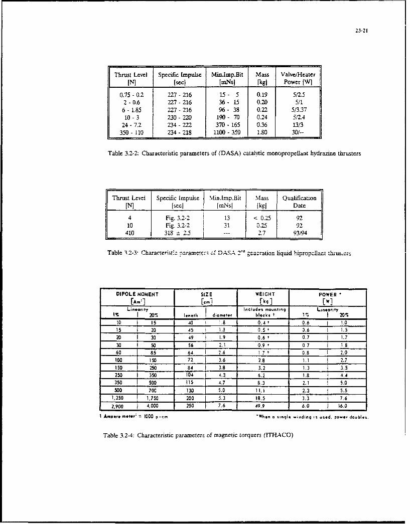
23-21
Thrust Level Specific Impulse Mindmp.Bit Mass Valve/HeaterIN] [secl [mNsJ [kgj Power [W]
0.75 -0.2 227-216 15 - 5 0.19 5/2.52-0.6 227-216 36- 15 0.20 5/1
6 - 1.85 227 - 216 96 - 38 0.22 5/3.3710-3 230-220 190- 70 0.24 5/2.4
24-7.2 234-222 370- 165 0.36 13/3350 - 110 234 - 218 1100 - 350 1.80 301--
Table 3.2-2: Characteristic parameters of (DASA) catalytic monopropeilant hydrazine thrusters
Thrust Levei Specific Impulse Min.lmp.Bit Mass Qualification[N] [secl f [rnNsI [kgi Date
4 Fig. 3.2-2 13 < 0.25 9210 Fig. 3.2-2 31 0.25 92
410 318 t 2.5 2.7 93/94
Table 3•2-3: Characterist:U -rametr-; 6.f DASA " ;eanration liquid 1bipropcilart
DIPOLE MOMENT SIZE WEIGHT POWER
[A.-] [,.I _ k_ _ _ [w]Linearity lnciudes mounting Linearity
IJ 20% lenoth diameter blacks t 11 . 20%
10 L 15 40 1 1,8 0.4 t 0.6 j !.015 20 AS 1.8 0.5 + 0.6 1 1,520 30 49 1.9 0.6t 0.7 I 1.7
30 50 56 2.1 09 t 0.7 1 860 85 64 I 2.6 1.7 10.8 0 2.0
100 ]SO 72 3.6 2.8 1.1 j 2.7150 250 84 I 3.8 3.2 1.3 3,5250 350 104 4.3 6,2 1.8 4.4
350 Soo 115 4.7 8.3 2.1 5.0
Soo 700 130 5.0 I,.I 2.3 5.51,250 1.750 200 5.3 _ 18.5 3.3 _ _7.6
2.900 4,000 250 7.6 49,9 6.0 1 16.0
1 Amoere meter- 1000 p-cm 'When o single windinq is used, power doubles.
Table 3.2-4: Characteristic parameters of magnetic torquers (ITHACO)

23-22
Wheet oiameter CM20 1 2 5Sl
Angt uiar montm range Nmne IA ... 6.5 5.0..20 14..80 50-100Max. reaction toroue NM 0.2 0.2 0.2 0.2Soeso.. *jMin 6000 ~ 6000 6000 600LMwo w &I Mua~mx. SPeOG) Nrn -0.012 ,c0.0 13 --0.015 -C0.0=2Powo consumotion:- $1sow dstate (do"enornq W 2 ... 7 2 ... 8 2 ... 10 3..I
an Speed)-max. power rating W <60 < 80 ~ 100 %150
Dimenswon:- diarneleA mm 203 260k 3W0 500
- heqtit8 mm 75 ass 120 150Weign kg 2.7_3.4 3.5...5 .a 5.0...8.0 75 ... 12
Environmentai coflabofls:
- operAunq temoeraiure-vibration I sinuso.*) suitantel tor satellites comostoe with launriers
- vibration tranoomi ISUMn aS AFIANE Or Soace ShuMe- linear acceweation
I lFAMi o ,w-aw-- -Mww nw~ai waa. wo at fea-si nw~it.no r eWwU ci mnwwwa" ~wo sa*wv* zWS2
Table 3.2-5. Characteristic parameters of momentum and reaction wheels (TELDIX)
Thrusters Thrust Orientation LocationLevel
Set A 4 N tilted in the S/C (x-,y)-plane on the corners of the ceL-- > zero z-component tral cube
Set B 4 N tilted in the S/C (.Yy)-plane on the corners of the cen---> zero z-component tral cube
Set C 4 N pointing in t K-direction on the edges of the S/C.-> zero y- and z-component parallel to the S/C y-axis
Table 4.2-1: Thrust levets, thruster locations and orientations

23-23
thruster activation thrusterno. 1 . 4
torqae re- I"I half modu- 2"' half mo-quirement lator time in- dulator time
crement increment
.1, -1, -1) (0,1,1,1) (0,1,1,1)0-1, ooo1) (0,0.0J)
-1. o1. (0,o,1,) (0,1.1,1)
1. ,0 (0,0,1,1) 0,0,1,1)0, 0. 1) (0.0.0).1 (1,.1u )
1( 0 1 -) (,0.1.,1) (0.1,0O)10 0.) (0,0,1,0) U1,0,1,1)
( ) o,.1 (u.io.) (oU a),11
(0,-1 0. , (()1.0.01) ( 1.1,0.1)
0, -1, 1) (00.1.0,1) (1,1 ,01)
0. 1, 0) (0,1.010)1 (0,I,10)
, (0,10.0,) (0,0,0,0)
0 , 1, -1) toolO) ,,,o0 , 1, o') (1,0,t,)(10 ,.)
IO. I. mu.().,00 (110:11)
I,-i-I) 0,10,0) (OAOO)1, 0) (0,1.0,0) (1,1,0.1)
____.-I _ ,1 (I.1.0.), (1,1.0,i)
1, 0, 0) (1,1,0.0) (t,1,100)
1, 1. 1ý LýA.Ao), 1i.o0.0o0
Table 4.2-2: Correspondance between torque requirements and thruster activation
SIC in orbit orientaton I SC in orbit o icrntation
Orbit normal Orbi! tan0entta Orbit Norma I Orbit tanientiai
Nominal Set A or Set B Set C Set C Set A Set B
B, Bckup Set Set AiB Set BiA Set A,!B or Set 2 remaainmn 2 remanamfltfB/A or Set C thrusters cl set A thriuters ot set B
re.sidual pitch distutbance torque compensated by set C
Table 4.2-3: Thruster activation for orbit corrections
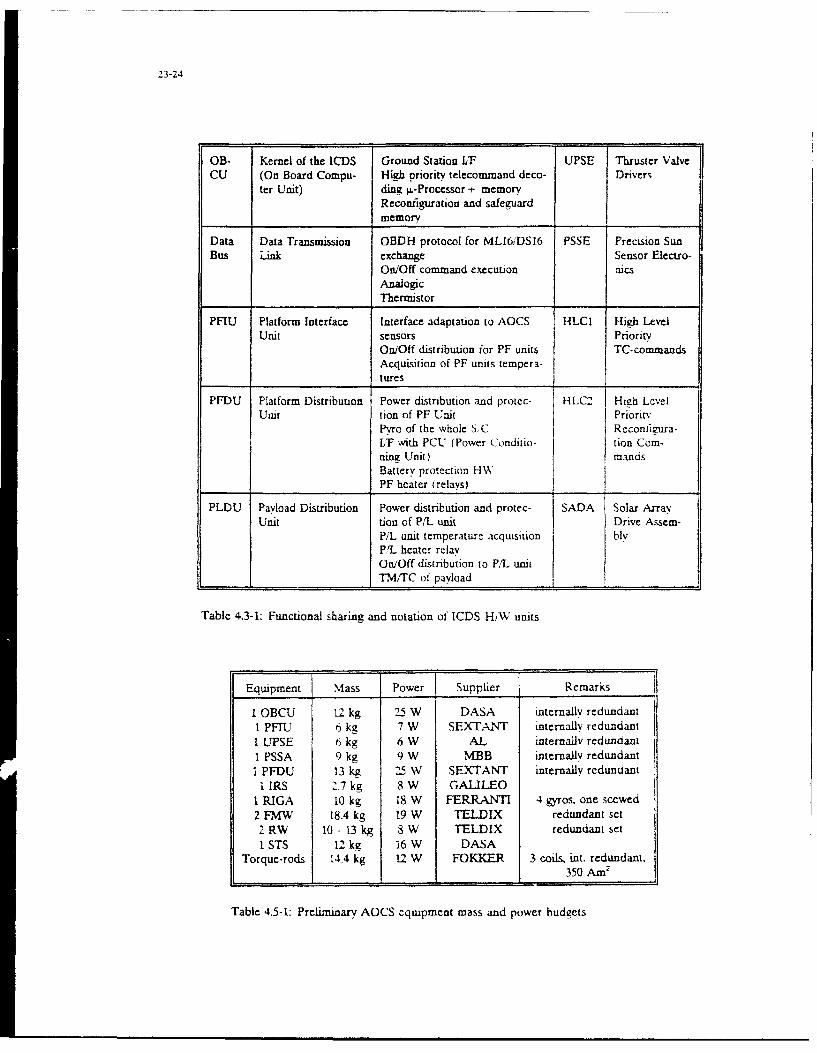
23-24
OB- Kernel of the ICDS Ground Station ILF UPSE Thruster ValveCU (On Board Compu- High priority telecommand deco- Driver-
ter Unit) ding wL-Processor + memoryReconfiguration and safeguardmemory
Data Data Transmission OBDH protocol for MLI6iDSI6 PSSE Precision SunBus Link exchange Sensor Electro-
On/Off command execution alcs
AnalogicThermistor
PFIU Platform Interface Interface adaptation to AOCS HLCL High LevelUnit sensors Priority
On/Off distribution for PF units TC-commandsAcquisition of PF units tempera-tures
PFDU Platform Distribution Power distnbution and protec- HLC2 High LevelUait tion of PF Unit Priority
Pyro of the whole S, C Reconimura-I/f with PCU (Power Conditio- tion Com-nina Unit) mandsBattery protection HWXPF heater (relays) _
PLDU Payload Distribution Power distribution and protec- SADA Solar Array
Unit tion of P/L unit Drive Assem-P/I unit temperature acquiMsition blvPL heater relayOn/Off distribution to P/L unitTM/TC of payload
Table 4.3-1: Functional sharing and notation of ICDS H/A units
Equipment Mass Power Supplier Remarks
I OBCU 12 kg 25 W DASA internally redundant1 PFEU 6 kg 7 W SEXTANT internally redundantI UPSE t kg 6 W AL internally redundantI PSSA 9 kg 9 W M]BB internally redundantI PFDU 13 kg 25 W SEXTANT internally redundant
. IRS 2.7 kg 8 W GALILEO1 RIGA 10 kg 18 W FERRANTI 4 gyros. one scewed2 FMW 18.4 kg 19 W TELDIX redundant set
2 RW 10 - 13 kg 8 W TELDIX redundant setI STS 12 kg 16 W DASA
Torque-rods 14.4 kg 12 W FOKKER 3 coils. int. redundant.350 Am2
Table 4.5-1: Prelininary AOCS equipment mass and power budgets

24-1
Electric Propulsion for Lightsats:A Review of Applications and Advantages
G. PerrottaAlenia Spazio S.p.A.
Via Saccomuro 24, )131 Rome, Italy
G. Cirri, 0. MatticariProel Industrie
V.le Machiavelli 29, 50125 Firenze, Italy
SUMMARY
The paper reviews the advantages and The paper reviews the key features oflimitations of electric propulsion for electric propulsion in the specificlightsats characterized by a launch mass context of DC-power limited iightsatsin the 300 to 800 Kg range. The considered characterized by a launch mass range insystems include ion propulsion, arcjets, the 300 to 800 Kq, which is mostand stationary plasma thitusters for appropriate for a number of 'professional'different applications such as draq applications, including civil and defensecompensation, orbit raising, line trimming ones.of orbital parameters, and various orbittransfers. 2. ELECTRIC PROPULSION FOR LIGHTSATS:
MOTIVATIONS A!ND CONSTRAINTSElectric propulsion provides substantial
mass savings and turns out to be an The main reason to consider electricenabling technology for certain lightsat propulsion is to reduce tne totalmissions. The constraints resulting from subsystem mass for propulsion-relatedDC power limitations onkx:ard small tasks, thus maximizing the payload tosatellites are discussed, along with the launch mass ratio while staying within theimplications on candidate technologies and launch mass bounds stated above. However,system solutions. A review of near term electric propulsion can be a viableprospectives of low power ion thrusters, approach only if the power requirementsfor lightsats applications, concludes the are also compatible with the DC powerpaper. limitations, considering thit the lightsat
power plant is normally designed to1._INTRODUCTION support the payload operation in normal
mode. We will limit our considerations toRecent advances in electric propulsion three E.P. technologies: ion propulsion,have finally led to consider its use for Stationary Plasma Thrusters, and arcjets.commercial geostationary communicationsatellites stationkeeping. For such In the low-power range of interest forfunction, ion thrusters, stationary plasma lightsats, typical performance are giventhrusters (SPT) and arcjets are currently in Table 2.-1 which envelopes thebeing planned on board several new characteristics of a number of existingsatellites. The main attraction of devices. Two main Electric Propulsionelectric thrusters lies in their high applications are considered:exhaust velocity which is several timesthat of conventional chemical thrusters. - orbit keeping, which includes dragThe major benefit is represented by the compensation, fine trimming of orbitpropellant mass reduction for orbit parameters and, for lightsats incontrol tasks. synchronous orbit, station-keeping. These
Electric propulsion is also being propulsion tasks are normally concurrentconsidered for other near Earth propulsion with payload operation. Therefore E.P.applications, see e.g. [1], in particular applications are mainly power limited,for orbit transfer and manoeuvering of besides being also mass limited in orderlarge spacecraft; and for scientific and to result competitive with chemicalinterplanetary missions, propulsion. To exemplify, we will assume
to allocate 30 Kg and 30C W to such E.P.For what concerns the electric propulsion functions;applications to lightsats, some initialwork results from the open literature, see - orbit manoeuvering, whi'h includes orbite.g. [2], but no specific plans are known raising, circular to e1liptical orbitto the authors about actually implementing transfer, and orbits circularization.electric propulsion onboard lightsats. These propulsion tisks ire performedThis is quite surprising because, in view outside payload operation. Therefore theof the specific constraints of small full lightsat DC power, norsally used tosatellites, electric propulsion may he supply the payload in normal mode, can beconsidered an 'enabling' technology made available for Electric Propulsion,without which a number of applications Typically, one may allocate 60 Kg and upwould be almost unfeasible. to 1200 W of DC power to E.P. functions.

24-2
E.P. Isp Spec.pwr Spec.mass ThrustTechnol. (sec.) (W/mN) (Kg/MN) (mN) With ion propulsion the applied thrustlevels are close to the drag force
averaged during one orbit period, i.e.from 3 to 15 mN for a typicdi smiil ARIon 2600-3400 25-30 2-3 2-60 satellite intended to 1, 1SPT 1400-1800 19-20 1., ?-so saelt itne o[y 'at orbitaltitudes as low as 300 Fm hrusts of
Arcjet 500-600 8-9 0.15 150-250 this order can be modularly aichieved by
Table 2.-1 Typical characteristics putting low power l 10 m.N) -on thrustersof three E.P.technologies in parallel and implemlenting throttling q:
in the low-power range on-off modulation iccording to therequired duty.
Considering typical values from Table2.-l, it can be seen that , for orbit- Orbit Crag t.ce Celta-V 2elta-V
keeping tasks, arcjets are severely power height avgd. over f Mo. 5 years
limited and are further penalized by the (Km) I orbit(mN) :m/s) fm/s)
poor Isp value. SPTs are good contenders a) b) a) b) a) b)
to ion thrusters, in that they can providehigher thrusts for the same DC power at alower mass, but the lower Isp value can be 275 30 15 1'55 385 11550 3852
critical for long-duration missions. For 300 21 10.5 `15 272 3150 2721
orbit manoeuvering the available DC power 350 14.2 7.1 551 134 5508 1840
is just at the limit where arcjets become 400 11.7 5.9 457 iý2 4752 1522
interesting; but SPTs also appear to be 450 8.9 4.4 ?.7 ii" 1 452 1152
good candidates, in view of the better Isp 500 7 I.5 :0 , " 700 902
they can offer. Other considerations, suchas the time to transfer, must then be Assumptions:
taken into account, in the system trade- * case a): SiC crcssectisn 4 m'2,
offs, to choose the right technology. drymass 400 Kg;• case b): SIC crossection Z -'2,
3. TYPICAL E.P. APPLICATIONS TO LIGHTSATS drymass 600 Kq:• worst year sun activity;
3.1. Drag compensation for Observationsatellites Table 3.1-1 Drag tcrces vs. altitude and
required delta-ve-locities for
Cost-effective observation missions can be their ccmpensatlonconceived with individual satellites,launched on-demand, or based on smallsatellites constellations carrying SAR (3)or optical sensors. In both cases the Table 3.1-2 gives propellant mass and DCmission requires very low orbit altitudes, power requirements of ion propulsion vs.say in the 280 to 600 Km range, to orbit altitude for a prospective small SARenhance the optical ground resolution or, satellite. For the considered thrustin the SAR case, to reduce the transmitted levels, the DC power requirements arepower compatibly with the limited compatible with spacecraft allocations. Inresources available on a small satellite, conclusion, ion propulsion has to be
considered an enabling technology toAt these altitudes the residual implement long duration observationathmospheric drag becomes th. limiting missions in very low Earth orbits.factor for the mission duration. Evenassuming a slender platform design and an Nevertheles, the operating time, of theorientation of tle appendages (i.e. solar order of 40000 hours, is of concern andarrays, antennas) such as to exhibit a should be properly iddressed by furtherminimum cross section in the direction of developments. Efforts to further improvethe flight path, the delta-velocity the efficiency of low power thrusters arerequired to counteract the residual drag also strongly reccomended.becomes .apidly unmanageable with chemicalpropulsion for mission durations greater Orbit Propell. Thrusters 1'/ Avge DCthan a few months: see Table 3.1-1. which height mass avge orb.duty poweris relevant to two typical lightsat (Km) (Kg)(1) (W),(2)configurations. The determining factorbecomes the propellant mass, given thelaunch mass limits. 275 90 2*8mN/0.94 450
300 62 2*8mN/0.66 320The high specific impulse of ion 350 41 SmN/0.88 240propulsion allows reducing, by a factor of 400 34 814N/0.74 200about 10 w.r.t. chemical propulsion, the 450 25 8mN/0.55 150propellant mass required to impart a given 500 20 SmN/0.44 120total velo!ity increment. As aconsequence, aission lifetimes of 5 years Note 1): based on 2800 s. Ispcan be achieved, which is instrumental to Note 2): based on 30 W/mNimplement small satellite constellationsfor 'permanent' observation missions. In Table 3.1-2 Drag compensation ioncomparison, the other E.P. technologies do propulsion requireients fornot perform well in this application system h) of Table 3.1-1characterized by very high requiredvelocity increments.

3.2 Fine trimming of constellations Table 3.3.-1 gives the essentials of anorbital parameters initial concept for a high performanceasmall geostationary satellite. BasicAn increasing number of small satellites features are the low power/low thrust ion-constellations is being proposed [4] for thrusters, the resulting overall low E.P.advanced communication and remote sensing system mass, the high achievable payloadapplications: most constellations have to satellite launch mass ratio, themultiple satellites in one or multiple absence of any kind of .chemicalorbital planes; low altitude orbits, propulsion.typically 400 to 1500 Km, are normallyenvisaged, with a few cases consideringaltitudes as high as 10000 Km. * Satellite launch mass (Kg): 600
* Payload mass (Kg) : 240Managing these complex systems will * Payload/launch mass ratio 0.4require copying with the launch systems * Orbital lifetime, years : 15orbit injection dispersions, as well as * Rqrd. total velocitymaintaining the satellites relative increment(m/s) Ni-S/S.K.: 700phasing during the orbital lifetime E-W/S.K.: 70against external disturbances. The * Ion thrusters number ' * 0 to 12quantization of these effects, in terms of * Thrust levels(mN) N-S/S.K.: 8mN (2*4mN)propellant mass, depends strongly from the E-W/S.K.: 4mN (2"2mN)launch vehicle characteristics, orbit type * Total prop.mass (Kg) : < 18and mission duration, and will not be * Avge dayly thrusting timeattempted here. The push towards launch N-S!S.K.: 2.66 hourscost reduction might probably imply, in E-W/S.r. 22 min.the near future, the use of less accurate * E.P. system mass (Kg) 3 20 (est.)L.V. and greater injection dispersions. * E.P. peak DC power 240There is also a clear trend to require Dayly energy needsrK;•h : 0,7longer orbital lifetimes. * Fea,}ihe control tornues
in pitch,roil,yaw 8*10-3 mBoth factors will tend to increase thepropellant mass allocated for orbit Table 3.3-i Main features o: a smallcontrol: this will impact negatively the geostationary satellite usingsystem economics, also in view of the small ion thrusteromultiplying effect due to the large numberof satellites In these constellations.Electric propulsion may be considered in 3.4 Circular orbit raisingalternative to chemical propulsion for thepotential mass saving it can provide, Several small launch systems are becomingspecially in presence of high orbit available, capable of direct injection ininjection dispersions and long orbital L.E.O. of spacecraft with launch masses inlifetimes. Constellation phasing is not a the 250 Kg to one ton rnrYe The L.V.time-limited propulsion task, which will payload carrying capability decreasesenable using low thrust, high specific rapidly, however, wilth circular orbitimpulse, E.P. systems. Suitable strategies altitude injection: therefore it may befor constellation phasing maintenance can preferable to inject in a rolatively lowbe conceived, possibly aided by autonomous orbit a more massive payload, comprising anavigation systems, to fully exploit the satellite and a boost motor, using theE.P. characteristics, latter for orbit raising. Typical cases
3may be represented by a coplanar orbit3.3 Stationkeepins of smallgeosynchronous raising from a 400 Km initial orbit to asa-teIlites final circular orbit of 800 to 2000 Km:
the resulting velocity increments areSmall satellites in geostationary orbit given in Table 3.4-i.can perform usefull communication,meteorological and observation missions. Chemical boost motors are normallyClusters of two to four spacecraft can envisaged for cost and technology maturityform a distributed satellite system having reasons, but their mass constitutes aenhanced performance w.r.t. a single significant fraction of the L.V. payloadsatellite of an identical total mass. and will reduce, in proportion, the
Assuming the availability of a launch satellite mass and its payload.
vehicle capable of directly injecting the Electric propulsion can be considered insatellites in synchronous orbit (such as, alternative, also because during orbite cg. the Russian Proton rocket) smaln raising the payload is not operative: thespacecraft relying exclusively on E.P. can full satellite DC power is, thus, inbe conceived. principle available for E.P., with the
The absence of a bulky apogee motor constraints given by earth eclipses.
greatly expands the spacecraft design Continuous thrusting is therefore assumedfreedom, including the positioning and only during 50 % of the orbit period, withorientation, or canting angle, of the E.P. the thrust vector tangent to the orbitthrusters. Spacecraft incorporating plane. Table 3.4-1 compares approximatelyseveral small thrusters may implement both estimated values for propellant mass andorbit control and external torques orbit tranfer times for the candidate E.P.compensation for attitude control. technologies w.r.t. a chemical one.

24-4
Final orbit altitude (Km) (1) First, very high delta-velocities are800 1400 2000 required, see Fig. 3.5-1. Second,
commercial communication satellites"* Delta-V.(m/s) 217 510 772 injected in elliptical orbits can be"* Prop.mass planned and launched well in advance of(Kg),(2): the need date. Long trip times are, thus,
- chemical (4) 48 120 190 relatively unimportant but mission- ion (5) 4.6 11 17 complexity, costs, reliability and- SPT (6) 8.2 19.5 29.6 operational considerations may put an- Arcjet (7) 26.5 64.6 100 upper bound to the maximum acceptanle trip* Trip time time.
(days) (3):- chemical <i < I <i Electric Propulsion alternatives to- ion 76 178 270 chemical are SPTs and arcjets, with the- SPT 51 120 180 same characteristics given in Table 3.4-1.- Arcjet 21 50 75 Simplified computations for transfers of a500 Kg spacecraft in transfer orbit from1) 400 Km initial circular orbit; an initial 400 Km circular orbit to three2) 600 Kg spacecraft destination elliptical orbits of 8, 123) thrust levels: ion= 40 mN; and 24 hours periods -ere performed.
SPT= 60 mN; Near-ideal transfer was simulated byarcjets= 150 mN; firing thrusters for I/4 of the orbit
4) Isp=280 s; 5) Isp=2800 s; period about the perigees until the final6) Isp= 1600 s; 7) Isp=500 S; apogee was reached, then tiring the
thrusters for 1/4 of the orbit periodTable 3.4-1 Electric Propulsion systems until the final perigee was also reached.for Orbit Raising Propellant 7ass rezuirodhy ýPTs and
arcjets are reported in ~ble 2.5-1.
Table 3.4-1 shows that low power arclets 5est nat'*nroit :1)are good candidates ror high altitude a) DJ c)differentials, providing good mass savingswith reasonable transfer times. On the ** Ideal Tranter:contrary, ion thrusters and SPTs are - Delta-V.marginal and can be only considered tor (m/s): 2350 2150 3450small altitude increments, otherwise too - T.O.mass!long tranfer times will result. In propell.massconclusion, low thrust electric propulsion (Kg) (2):can be considered for circular orbit chemical 1157.'657 1243,743 1714/1214raising of small satellites when a short arcjet n00/30.3 332/332 996/496transfer time is not mandatory. SPT 579/79 586,/86 620/120
When orbit raising must be implemented in ** Non-idual Transter, Arciet:a very short time, as for example with - T.O. mass/satellites launched on-demand, then propell.masschemical propulsion is still the preferred (Kg) (3) : 858/353 898/398 1105/605approach. - Trip time
(days) 363 -94 5303.5 Circular to elliptical orbit transfers _
Cnaracteristics or Zest.,naticn Orbits:Elliptical inclined orbits are being a) Apogee:32430 Fm; Periiee:8107 Km:considered wit-, Increasing interest for Period: 3 hours;numerous applications, and there are plans b) Apogee:45150 Fmn teriqee:-968 Ym;to realize small satellite constellations Period:12 hours:exploiting the particular features of such c) Apogee:59030 Km; Perigee: 25298 Fn;orbits. However, the injection capability Period: 24 hours;of small launchers in elliptical, high Note 1) Starting orbit: circular, 400 Km;energy, orbits is normally rather poor, " 2) Satellite drymass: 500 Eqand one has , again, to rely on boost " 3) Including Delta-V increment (15%)motors to implement the final orbit for non ideal transfertransfer, for which two importantconsiderations apply. Table 3.5-1 E.P. alternati';es to chemical
propulsion tor circular tothe. .elliptical orbits tranfers
For the arcjet case, .3 non-ideal transferwas also simulated, ind the propellantmasreopue tiniInto account a 15%,mass recomputed taking
-ý worsening in the delta-velocity requireddue to :he non-ideal tranter conditions.As can be seen the trip times are quite
34 0' high in all cases: a 30 % reduction can be" achieved increasing the arcjet thrust to
*. . $ 8.i RA O's 18 ..6.. 220 MN, which would nevertheless imply theavailability of 1.8 Kw DC power. This
. ......... . . might necessitate an auxiliary array inthe E.P. boost section, impacting costs.

There are several additional positive and and logic should be set as near termnegative factors, to be taken into development objectives. Isp values betteraccount, which may affect the trip time; than 3000 sec., and very long lifetimes,but in conclusion the feasibility of using of the order of 40000 hours, are alsolow power arcjets in power limited primary requirements;lightsats for low altitude circular toelliptical orbits coplanar transfers has - low power arciets in the 1 to 1.2 Kwtbell consideoredtstlprlemartic.sfs h range, for orbit manoeuvering tasks. Forto be considered still problematic. such devices efforts should be devoted to
3.6 Orbits circularization possibly bring the Isp closer to 600 sec.for thrusts in the 150 to 250 nN range,
This propulsion task refers to satellites, with an overall specific power better than
injected in elliptical transfer orbit by a 8 W/mN including power supply.
L.V., whose final destination orbit iscircular with a radius normally coincident On the other hand stationary plasmawith the T.O. apogee. Typical cases are thrusters do not seem to have a clear rolegeostationary orbits and medium altitude for lightsats, at least in their presentcircular orbits of about 10000 Km as power and tbr' - level range. Scaling down
envisaged, for example, by TRW's odyssey SPTs to low chrust values (say below 10and ESA's MAGSS-14 constellation [5]. mN), while keeping unchanged theirexcellent performance, in particularElectric propulsion is compared to efficiency and simplicity, is yet unprovenchemical in Table 3.6-1. for these two but might be worth being investigated.typical missions. Arcjets are found toperform acceptably well in this case, 5. NEAR TERM TECHNOLOGY PROSPECTIVES OFsince trip times around 200 days can be LOW POWER ION THRUSTERSachieved along with significant mass For the considered thrust range, newsavings w.r.t. a chemical propulsion device basedeon theEctron nalternative. The better mass saving devices based on the Electron Cyclotronachievable with SPTs is, instead, paid(ECR) are presently under
with an excessive trip time duration, evaluation, aiming to further improve theion thruster's performance.
** T.O. characteristics:- Perigee (Km) 6678 6778 The ECR technique allows cperating over a- Apogee (Km) 42164 16728 wider thrust range by changing the mass** Destination Orbit flow rate in the discharge chamber
characteristics: enhancing the electrical efficiency and- Radius (Km) 42164 16728 gas consumption over a wider pressure- Velocity increment, range than the conventional RF and Kaufman
ideal transf.(m/s): 1476 1174 technologies. ECR appears particularly** T.O.mass/propell.mass indicated for small size ion thrusters,
(Kg) (1) (2) : for which it is also easier to achieve the- chemical 844/344 760/260 optimum static magnetic field necessary- arcjet 700/200 655/155 for resonance.- SPT 555/55 544/44
* Trip times (days): The ECR technique consists in applying a- chemical <1 <1 static magnetic field , orthogonal to the- arcjet 227 182 direction of an oscillating RF field, so- SPT n.a. 453 that electrons are forced to rotate within
the thruster's discharqe chamber, aroundNote 1): Satellite drymass 500 Kg; the magnetic field lines at a cyclotron
"2): Including a 1i increase in delta frequency given by: Fc= eB/27m. The meanvelocity due co non-ideal tranfers energy per collision, transferred to an
Table 3.6-1 E.P. alternatives for Orbit electron, is:
Circularization Wc= (e*E'/4m) (l/(4Tr (F-Fc) (I/'-')), with:
B= magnetic field; e= electron charge;
4. REVIEW OF SYSTEM NEEDS m= electron mass; E= applied electricfield peak amplitude; T= mean time between
From this overview two E.P. technologies two consecutive collisions, inversely
appear to have a future on power limited proportional to gas pressure; F= frequency
lightsats: of the applied RF field.
- small ion thrusters for drag At resonance F=Fc, and the quantity Wccompensation, limited orbit raising, orbit assumes its maximum value: Wc - feEK)1/4m,circularization and fine trimming of which depends only on collision interval
orbital parameters of small satellites, and electric field peak value. Clearly the
The required thrust levels are in the 2 to maximum benefits cf the ECR effect is
10 mN range. a modular approach enabling achieved in the low pressure range, being
parallel operation of thrusters ir also the collision frequency proportional to
required. Full thrust control, over a 30% the operating gas pressure.to 120 % range of the design thrust level,is an important design requirement. An For a ion propulsion system in theoverall specific power of 40 W/mN maximum millinewton range a RF excitation in the
(30 W/mN as a goal), and a specific system VHF range proves advantageous for themass of less than 1 Kg/mN maximum (0.7 following considerations:Kg/mN as a go~l), including power supply

- it is possible to use a low level static - The ECR technique .s speciallymagnetic field to reach the resonance advantageous for ion thrusters operatingcondition, e.g. 36 Gauss for resonance at at low thrust levels ( 2.10 mN) where it100 MHz. A lower thruster mass can be thus reduces considerably the instabilityachieved; phenomena inside the plasma. Low thrusts
are related to small chamber dimensions,- since the wavelenght is much higher than which simplifies the realization of athe chamber dimensions, problems arising uniform magnetic field in the dischargefrom energy propagation into plasma can be vessel, and requires less DC power.avoided. In case of VHF excitation, plasma A -,all chamber also requires smallgeneration is infact achieved through a electrodes for electromagnetic energy"near field" mechanism so that no cut-off transfer, with lower losses due to EMfrequency exists; irradiation and vessel walls absorption.
- it is possible to use coupling Furthermore, for constant average beamelectrodes, for the VHF RF field, outside current densities, thruster throttling isthe discharge chamber, due to the limited accomplished keeping the mass flow ratepower losses for itradiation and to beam area ratic constint. A reducedabsorption in the chamber walls, compared flow rate is associated with a pressureto the usefull power transferred to the regime within the discharge chamber whereplasma. ECR proves more efficient and stable than
other traditional excitation techniques.considering a thrust level in the 2 to 10mN range, and a cylindrical discharge - The grid extraction system can 7echamber of 3 to 5 cm radius, three designed and optimized on the basis of theconditions are required to fully exploit enhanced plasma characteristics typical ofthe ECR benefits: the ECR technique. In this direction PPOEL
is investiqatinq ilso new technologiesI) F >> l/T, '.e about 2 MHz considering !patent pendinq) tor the realization C!a pressure of 10-4 Torr and an electron grids with i geotetry nvving a highenergy of 13eV. This condition ensures transparency 'actor to Ions, whilethat electrons turns around the magnetic maintaining good mecnan~lac resistance andfield many times between consecutive the capability to survive to sputteringcollisions; erosion.
2) R < 1 cm, where R is the gyration The use of a high meiting point refractoryradius of the electron in presence of a material, coated wIth cuitablemagnetic field directed along the chamber antisputtering protection layer, is theaxis. This condition ensures that the solution to long lotetime requirements.electron trajectories are contained in thedischarge chamber: 6. CONCLUSIONS
3) EM field wavelenght >> 3+5 cm. This Electric propulsion, and in particularcondition avoids propagation problems in advanced ion propulsion, 's an enablingthe plasma, technology tot the leasibility of very low
Earth orbit missions, In power-limitedIn summary, the ECR technique is expected lightsats, where Irag is the dominantto provide substantial improvements in low effect.power ion thrusters performance, enhancingthe advan~tages of traditional RF techniqes Furthermore, low power 0on thrusters are ain combination with others typical of the good system alternative 'or propulsionKaufman technology. The main features o0 tasks requiring the steady 3opplication ofthe ECR technique are summarized os low thrust levels over extended periods offollows: time to implement a given velocity
correction. Nevertheless very long- ECR sources do not have components lifetimes, of the order of 20000 to 40000subjected to wearout, as cathodes or hours, must be reliably demonstrated.accelerating electrodes, in the plasma Improvements in mass and power efficiencychamber. of such low power thusters would also
benefit the lightsats design.
Problems of sputtering erosion inside the Low power arcjets, in the 1 Kw range, havechamber are thus eliminated, impacting also promising applications for certainpositively the thruster lifetime, orbit manoeuvering tasks, and theirMoreover, it is possible to realize the development should be further pursued.discharge vessel with materials havinghigh secondary electron emissioncoefficients, scarcely sensitive toerosion and capable of reducing electronlosses from plasma towards the vesselwalls.
- The plasma produced by the ECR is highlyuniform, both in density and temperature. REFERENCESAchievable electron densities are of theorder of 10^12 electrons/cm^3 at pressures [1] j. Reale "A low altitude ion-propelledin the range of 10^-4 1 10-5 Torr, thus remote sensing spacecraft "; 22ndfacilitating beam extraction optimization. IEPC; Viareggio, October 1991;
[2) G. Perrotta, M.Biaconi, A. Bicci, [4] G. Perrotta " Emerging new conceptsM.Capacci,G.F.Cirri,G.Matticari: " Orbital for non-GEO satellite networks: a review";control and manoeuvering of lightsats / ICCC '92; Genoa, October 1992:synchronous satellites: assessment of newion propulsion technologies based on the [5] J. Senedicto, J. Fortuny, P. RostillaElectron Cyclotron Resonanc. phenomenon to " MAGSS-14: a medium altitude globalimprove the performance of thrusters in mobile satellite system for personalthe milliNewton range"; 22nd IEPC, communications at L-band"; ESA JournalViaregqio, October 1991; Vol.16 N" 2, 1992.
[3) G. Perrotta " SAR sensors on tACSATS:a feasibility assessment"; thisconference;

25-1
An Overview of DARPA'sAdvanced Space Technology Program
Col E. Nicairi 1 and J. Dodd
2 *
1. Defense Advanced Research Projects Agency 2. The Aerospace CorporationAdvanced Systems Technology Office Suite 79003701 North Fairfax Drive 955 L'Enfant Plaza. S.W.Arlington. VA 22203-1715 Washington, D.C. 20024-2174
1. INTRODUCTION enhance support to operational commanders byIn the three decades that have elapsed since the beginning developing and applying advanced technologies that willof the space age. satellites have increased in performance provide cost-effective, timely, flexible and responsiveand capability by orders of magnitude. Demands for more space systems. Fundamental to the ASTP effort is findingcapacity have, in many cases, been met by merely new ways to do business with the goal of quickly insertingincreasing the size and weight of the satellites, with more new technologies into DoD space systems while reducingchannels for communication or more memory or more cost. In our view, these methods are prime examples ofprocessing capability, but still representative of the what may be termed "technology leveraging."existing state-of-the-art. In general. the size of satelliteshas grown significantly over the early trail-blazer The ASTP is a multidisciplinary technology developmentversions with their admittedly limited capabilities. Yet, effort aimed at quickly exploiting advanced technologies.there are indications that we still have a long way to go Included in the program are:before the ultimate limits are reached in "making thingssmall." Sponsorship of the initial launches of the
Pegasus Air-Launched Vehicle (ALV) and theIn the present economic climate, it appears certain that development of a Standard Small Launch Vehiclethere will be significant cutbacks in most areas of the (SSLV):defense budget, including military space systems. TheDepartment of Defense (DoD) and the defense industry will - Development of enabling technologiesbe expected to design and field more advanced and more subdivided into satellite support subsystems,efficient space systems. These newer systems must, and satellite payloads and communication terminals;will, make even more use of miniaturized, high technologycomponents than are incorporated in our current stable of - Development and launch of small satellites forsatellites. Using this philosophy, future systems can be demonstration to and evaluation by the military.expected to have equal, if not greater, capabilities than Services. Included in this area are the Multiplemost of the current systems on a unit weight basis. Upon Access Communications Satellite (MACSAT)implementation of this philosophy of reduction in the size program and the Microsat program;and cost of both satellites and their booster rockets, wewill have made major steps toward synergistically . Development of a standardized. multimissionsatisfying emerging national needs for responsive and common bus under the Advanced Technologyreconstitutable space systems. Standard Satellite Bus (ATSSB) program: and
The Defense Advanced Research Projects Agency (DARPA) Development of two advanced technologyis the central research and development organization of the satellite demonstrations scheduled for launch inDoD and, as such. has the primary responsibility for the the mid. 1990s. The Advanced Satellitemaintenance of U.S. technological superiority over Technologies for EHF Communication (ASTEC)potential adversaries. DARPA's programs focus on program will develop and launch two EHFtechnology development and proof-of-concept payloads. The Collabora'ion on Advanceddemonstrations of both evolutionary and revolutionary Multispectral Earth Observation (CAMEO)approaches for improved strategic, conventional, rapid- program will develop and launch a multiple-use,deployment and sea power forces and on the scientific remote sensing, multispectral payload.investigation into advanced basic technologies of thefuture. DARPA can move quickly to exploit new ideas and The ASTP has initiated over 50 technology projects, manyconcepts by working directly with industry and of which have been completed and transitioned to users.universities. The objectives are to quickly qualify these higher risk
technologies for use on future programs and reduce the riskFor four years, DARPA's Advanced Space Technology of inserting these technologies into major systems, and toProgram (ASTP) has addressed various ways to improve the provide the miniaturized systems that would enable smallerperformance of small satellites and launch vehicles. The satellites to have significant -- rather than limited --advanced technologies that are being and will be developed capability. Only a few of the advanced technologies canby DARPA for small satellites can be used just as easily on be described here, the majority of which are applicable tolarge satellites. The primary objective of the ASTP is to both large and small satellites.
* The authors wish to acknowledge the valuable contributions of LTC Robert 1. Bonometti. DARPA. and John Draim.Space Applications Corporation.

.25-2
2. ENABLING TECAINOLOGY PROGRAMS this project include a star pattern recognition algorithmthat eliminates the need for an initial attitude acquisition
2.1 Subsystems sensor (i.e., no sun or earth sensor is required) and genericA significant portion of the ASTP effort is devoted to the applicability to all thrce-axis. stabilized spacecraft.development of satellite subsystem technologies.Subsystems such as power supplies, attitude determination."and control devices, communications, computer ' c_..processing and memory storage, propulsion units for -' "stationkeeping and repositioning are, of necessity,present on virtually every satellite (whether "light" or"heavy"). All of these items contribute to the weight of N"" -'
the satellite on-orbit; thus, major reductions in weight and,ost not only benefit the satellite, but also aid in reducingthe size and cost of the booster vehicles that put them inorbit. The ultimate objective is to minimize the size and -e-maximize the efficiency of launches vehicles and thesatellite bus so that the "business end" of the the spacesystem -- the payload -- comprises a much more significantfraction of the overall satellite weight.
2.1.1 Lightweight Reaction WheelThe Lightweight Reaction Wheel (LRW) is a magneticallysuspended reaction wheel with redundant electronics that Figure 1. Miniature GPS Receiverwill provide five times the momentum of existing units atthe same weight, with growth potential to ten times the 2.1.4 Inflatable Torus Solar Irrav "hchnoloeymomentum, by using magnetic bearings in lieu of ball Solar arrays typically provide spacecraft power. Atbearings and faster rotational speed. The LRW requires ,.resent, as the amount of power required increases, the site25 percent less power and can be used on all satellites; its and weight of the solar arrays increase -- a situation thathigher speed and reduced bearing vibration potentially can necessarily constrains the capabilities of payloads onbenefit operation of onboard sensors (e.g., less "blurring" small satellites. The ASTP's Inflatable Torus Solar Arravof a sensor's image). This effort is aimed at the design and Technology (ITSAT) project aims to make possible spacedelivery of a prototype LRW for testing and subsequent use missions that are otherwise impossible by providingon a satellite. The prototype LRW will be flown on an increased available power while maintaining small launchupcoming Air Force Space Test Program flight, volume, and weight. An inflatable, self-rigidizir.g tonus
structure supports the solar ceil blanket. The modular2.1.2 Miniature Global Positioning System Receiver desipn -'lows for easy insertion of new solar cellThis effort is a technology development project to design, teel- including thin film arrays. The current ITSATfabricate, develop, deliver and demonstrate, in an under development has desigi goals of 100 watts/kg andoperational environment, a space-qualified. multichannel 120 waits/m 2 .Global Positioning System (GPS) receiver than can be usedto support autonomous navigation onboard spacecraft 2.1.5 Miniaturized, Low-Power Parallel Processor(Figure 1). The GPS receiver will enable the simultaneous The basic goal of the Miniaturized, Low-Power Parallelreception of multiple GPS navigation signals, thereby Processor technology development project is theproviding greater position accuracy in comparison with reduction, by an order of magnitude, of onboard processorcurrently available receivers that sceuentially receive the size. weight and power consumption tor space-basedmultiple GPS navigation signals. The use of gallium sensor systems. Such processors must employ massivelyarsenide (GaAs) technology has enabled this more parallel architectures with large numbers of processing"powerful" receiver to fit in a much more compact package elements in :der to aciieve the high throv"hputs required(one-tenth the size of previously space-qualified (up to tens of billions of operations per second or more).receivers). The GPS receiver is scheduled to "fly" on The approach for achieving this goal is to use three-several space missions beginning in 1993. dimensional, hybrid wafer scale interconnect and
packaging technology. In this concept, individual2.1.3 Attitude Determination, Control and Navigation modules with multiple, unpackaged semiconductrr chipsSystem are compactly interconnected into a high density packageA single, fully integrated guidance, navigation and control with substantial weight and power savings over existingsystem is being developed under the Attitude packaging approaches (Figure 2).Determination, Control and Navigation System (ADCNS)project. It will use low cost star trackers, fiber optic 2.1.6 Magnetic Disk Mass Memorygyros, generic VHSIC space-borne computers and the Rotating disk memory subsystems have been a leadingASTP-developed GPS receiver (see paragraph 2.1.2). The technology product for many years. Although not widelystrap-down star tracker is designed to determine attitude by applied to space applications, they represent ztate-of-the-recognizing star patterns via an acquisition search pattern art for high density, mechan~cal memory subsystems.(a slow attitude change maneuver) and maintain that They are less complex and have fewer potential mechanicalattitude determination in any orientation via nearly failure points than traditional spaceborne tape recordercontinuous star tracking. Low cost, highly reliable fiber systems. The objective of the Magnetic Disk Massoptic gyros provide attitude determination during high Memory project is to develop a magnetic rotating diskslew rate maneuvers, smoothing between star sightings memory subsystem that will provide up to I Gigabyte ofand rate stabilization. Spacecraft autonomy is maintained high-speed data storage. The effort will review availableby using the GPS for navigational updates. Advantages of optical and magnetic disk equipment, determine the

25-3
radiating aperture. Feedhorns are arranged with equalspacing on a concave spherical surface adjacent to the
Substrate Holder HWSI Substrate dielectric sphere. To form an electronically scannedEiastcmenc antenna, any one of a large number of feeds is excited
Heat Sink -- through an interleaved, switched tree network. which cancombine clusters of horns to perform complex nulling or
, can be used for simple switched beam operations. The size- - of the lens depends on the minimum gain requirement
.0 -(e.g.. for 25 dB minimum gain. the lens would measure,", approximately 2.5 inches in diameter at a frequency of
A.f E , 44.5 GHz). The estimated size of the antenna (lens./ horns and switch tree) is 12-inch diameter cylinder and
73mm 10 inches long." 57mm--"'
2.2.2 U1IFThe most widely used and, unfortunately, most vulnerable
Figure 2. Miniaturized, Low-Power Parallel Processor military satellite communication (MILSATCOM) trequencyUsing 3-D HWSI band is UHF. The Multiple Path, Beyond Line-of-Sight
(MUBL) Communication effort is aimed at providingphysical and environmental requirements for operation interference-resistant voice communications amongaboard a spacecraft, and design and fabricate an enclosure affordable, handheld UHF terminals having approximatelysuitable for space flight. 5 watts of RF output. The concept provides a single-hop
capatility (as seen by the user terminal); it may be thought2.2 Payload Technologies of as an amplifying ionosphere. No satellite crosslinkingIn addition to providing more room for payloads on is contemplated. When more than one satellite is in viewsatellites, we intend to increase the number of bits or of the communicating terminal pair. there are multiplepixels per pound for communications and optical propagation paths. The modulation and coding system ispayloads. Several projects have been initiated to do just designed to support this and resist interference from otherthat. In this section, we discuss some of our EHF. UHF and satellites. In addition to satellites. MUBL can be mountedlaser communication initiatives and several of our optical on high altitude balloons, mountaintops or unmannedtechnologies initiatives, aerial vehicles. Successful implementation of these
concepts could substantially alleviate shortcomings noted2.2.1 EIIF in the recent Desert Storm operations.
2 2.1.1 Payload Concept 2.2.3 Satellite/Submarine Laser CommunicationsThe most promising, new, near-term technology for Initiativesprotected communications employs the EHF band A number of laser communications studies and(approximately 44 GHz uplinks and approximately 20 GHz demonstrations are underway or have been completed bydownlinks). The ASTP has several technology projects the ASTP. Their common objective is to develop reliable.underway that synergistically complement and support two-way laser communications systems. For submarinesother DoD work in the EHF arena, including the having expanded operational depth and speed envelopes.application of advanced technologies that would laser communications provides the potential for timelysignificantly reduce the size, weight, volume and power message delivery at useful transmission rates. Currentrequirements of existing EHF systems. We are striving for submarine communications can be enhanced through thea 65 percent reduction in required power compared with the use of blue-green laser technology. Submarine laserpresent technology base. Within five years. further communications systems will require smaii. lightweight,technology advances should provide an additional prime power efficient lasers and narrow spectral band, wide30 percent reduction in weight and power. Presently, our field-of-view optical filters. The ASTP has several blue-studies indicate a payload weight of approximately green laser projects that address these challenges. At67 pounds for a 35-channel, low data rate (LDR) EHF present. these development cffortv focus on the Cesiumpackage is possible (compared to the existing 225-pound Atomic Resonance Filter (Cs AR.,; and alternate narrowpackagc). A highly efficient, 2 watts. 20 GHz bandpass filters, as well as several laser transmittertransmitting, high-power amplifier yields an overall technologies. All of these technologies are beingefficiency of at least 35 percent; it uses a recently developed for rapid insertion into candidate spacebornedeveloped (DARPA-sponsored) GaAs permeable base laser communications systems.transistor. Also being developed for this project are ahigh-speed signal processor, lightweight signal generator 2.2.3.1 Cesium Atomic Resonance Filterand lightweight scanning antenna. The 44 GHz scanning The Cs ARF project is designed to investigate enablingantenna has a variable beamwidth, making it capable of technologies to support satellite-to-submarine laseroperating in elliptic, as well as circular, orbits. communications, Specific areas of investigation are
satellite system concept definition and uplink receiver2.2.1.2 Spherical Lens Antenna breadboard design development and testing. The Cs ARFThe Spherical Lens Antenna project has as its objective receiver approach utilizes a unique side-coupled Cs ARF asthe development of a wide field-of-view (WFOV), the basis for the 4-cell array (Figure 3). This approachelectronic scar ing. multibeam EHF antenna capable of provides very good broadband signal rejection withnulling interfering signals and operating in a variety of exceptionally high inband signal throughout. Ourorbits, including those that are highly elliptical. The findings to-date have resulted in an order of magnitudeantenna's radiating aperture is a sphere of solid dielectric improvement in cell efficiency from 4 percent to overthat provides a graduated index of refraction to form the 47 percent.

25-4
2.2.4 Optical Initiatives IPSRU synthesizes the equivalent of an inertial star tanSeveral research contracts for optical studies and optical probe beam) that is injected into the path of abreadboard demonstrations are completed or ongoing. The payload's telescope (Figure 5). This inrtial star providesobjective of these projects is to advance the state-of-the- the means for closed-loop payload focal planeart in satellite technologies for electro-optical sensor stabilization, which will eliminate the effects of jitter andsystems. transient distortions on the focal plane and the telescope
structure.BLUE LIGHT
FILTER BLOCK$ RED ,tr ]
Figure 3. C_.s AHF (Cross-Seda~n) Figure 5. IPSRU
2.2.4.1 Phased Array Mirror, Extendable Large Aperture 2.2.4.3 Electron f'arne~n• SensorAperture size of present space-based optical systems is Sensors for a wide range of signals are of primarylimited by cost and availability of a vehicle to launch a importance for advanced systems in aerospace guidancelarge, massive, primary mirror. The Phased Array Mirror, and control, robotics, target imaging and other importantExtendable Large Aperture (PAMELA) project is applications. The uitlascnsitive electron tunnel sensor.developing the technology to build a mirror composed of recently developed at Jet Propulsion Laboratory, haslightweight segments that cant be folded for launch and applications in advanccd accelerorneters. hydrophones.automatically space-deployed to form a large aperrture, magnetometers and room-temperature infrared detectors.(See Figure 4). The technology will develop and integrate The tunnel sensor is based on the quantum-mechanicalsegment sensors and position actuators with control electron tunneling mechanism used in the scanningalgorithms for accurate remote deployment and active turnneling microscope, which won the 1986 Nobel Prizesurface control. Miniature sensors on all adjacent edges for Physics. A compact tunnel sensor with the size andsense relative segment offset. These sensors, considered mass of a penny has been micromachined from a siliconkey to the technology, have been demonstrated, wafer. Because the tunnel sensor can be fabricated in
silicon, it is possible to fully integrate the tunnel sensor--- ,z-o,,,, -. with its microelectronics in a monolithic silicon package.2.3 MILSATCOM Terminal Technology
Z
DevelopmentDARPAFs IMPACc (Insertion into MILSATCOM Productsof Advanced Communications Technologies) Program is a
ls- obi- multidisciplinary technology development effort aimed ang phased insertion of advanced technologies im to
se MELTr MILSATCOM terminal systems. The fundamental goal of
this program is to reduce the life cycle cost of theI •,o• I MILSATCOM terminal segment with associated reductionso in terminal y d e, weight and power consumption and
enhancements in performance, reliability and capabilities.
utoSmNt ic all MILSATCOM terminal programs with technology
OF SGME.TS :?:]:•"insertion initiatives. retrofits and upgrades. as well as"e F e 4enabling technology developments in support of next-
s t s aith c l generation terminals.
aui Aepentuan MILSATCOM systems currently encompass a diversemultitude of terminals that are designed to interface with
Figure 4. PAMELA several different types of satellites operating in threeMILSATCOM bands. Each frequency band offers particular
2.2.4.2 Inertial Pseudo-Star Reference Unit advantages and complementary charcteristics to theThe inertial Pseudo-Star Reference Unit (IPSRU) project is overhlll defense space architeture.developing a single unit for precision pointing andstabilization of optical payloads. It will compensate for IA addition to this diversity, the terminal populationmechanical flexural movements, thereby allowing the incorporates numerylos distinct system implementations.incorporation of less stiff and lighter structures. The including manpack and man-portable terminals: mobile

Significant technological advances occurred during the 16-sided prismoidtime that most of the infrastructure was acquired: however, 24-inch diameter, 14-inch heightit is not cost effective for DoD to procure a new suite of 136 poundsterminal systems despite the enhanced performance, novel Gravity gradient stabilized, assisted by magneticcapabilities and other advantages that new technologies Z-coilhave to offer. Instead, innovative product and process Semi-monocoque constructionstrategies are needed to modernize and upgrade the existinginfrastructure by inserting advanced technologies into The MACSATs are placed in a near polar circular orbitcurrent systems. In this way. new technologies can be (89.9 degree inclination) at 370 nautical mile altitude. Upexploited in a manner that leverages our prior investments to 1,024 mailboxes may be accessed. Thein the MILSATCOM architecture, communications package operates with UHF frequency
shift keying (FSK) receivers and either a 10-wattSince a fundamental goal of DARPA's IMPACT Program is transmitter or a 60-watt high power transmitter. Thesuccessful and immediate technology transfer, close standard data rate is 2.4 Kbps. although demonstrations atcoordination has been established with key organizations 4.8 Kbps have Dean accomplished. The electric powerand programs in the MILSATCOM community. These key subsystem uses a body-mounted, 54-solar cell array and aplayers include system users, technology developers in 144-watt-hour commercial nickel caomium (NiCd) batteryService laboratories, terminal product management pack. operating in an 18-volt DC bus.offices, the executive management for the MILSATCOMArchitecture, the Defense Science and Technology 3.2 MlcrosatProgram, and agents for execution of the program. A second constellation of seven communication satellites.
weighing 50 pounds each, were launched on a singleIMPACT will work closely with the MILSATCOM terminal Pegasus ALV on July 17, 1991. The satellites (known ascommunity and with technology developers. By Microsats) were designed to provide intra-theater voice orconducting an integrated, coherent effort, IMPACT will digital communications along with some store-and-forwardsynergistically leverage ongoing work within this digital data transfer. The electric power system includedcommunity and winiin industry to achieve the product- and 18 solar panels with a 50-watt-hour commercial NiCdprocess-oriented goals of the program. battery pack, a 5-volt linear regulator and a 5/15 volt
DC/DC converter. The attitude control system included anIMPACT will serve as a testbed and role model program for earth sensor and magnetometers for reference, torque rodsthe nlw era of defense acquisition in which budgetary for spin-up and a 1.1-liter nitrogen tank forconstraints necessitate reduced fielding of new systems and stationkeeping. The communications system itlowed forgreater emphasis is placed on research and development, either analog or digital communications. A digitally-This program will pioneer the leveraging of R&D to controlled UHF FSK 10-watt transmitter and FSK receiverupgrade, sustain and modernize existing fielded equipments allowed voice communications or up to 4.8 Kbps digitalin order to maintain the competitive technological data rate. Omni-directional blade antennas were deployedadvantage that the U.S. now possesses in defense on both sides of the spacecraft.capabilities.
Microsats had the following characteristics:3. LIGHTSAT COMMUNICATIONS 12-sidedTECHNOLOGY DEMONSTRATIONS 19-inch dia;,,eter. 7.5 inch heightAnother activity addressed by the ASTP is the actual on- Deployable antennasorbit demonstration of complete systems. This provides Spin stabilized"proof of the pudding" for all the preceding phases of R&D • Nitrogen cold gas propulsioneffort in systems studies. and subsystem and componentdevelopment in the form of conclusive on-orbit The Microsats were designed to he ejected from the carrageoperations. in such a manner as to place them in a single orbital plane
with 400 nautical mile altitude circular orbits. Although a3.1 MACSAT launch -chicle anomaly resulted in a much lower orbitalThe initial constellation of DARPA lightsats was launched altitude, the correct inclination and satellite spacing wason a Scout booster in M'ay 1990, two years after startup of achieved. A very successful demonstration program wasthe program. It included two UHF store-and-forward completed before the satellites re-entered the atmospheresatellites, the MACSATs. It was planned to demonstrate approximately six months after launch.their operation to tactical commanders in as realisticenvironments as possible. The demonstrations would 4. ADVANCED TECHNOLOGYdisplay global message relay for manpack terminals, to be DEMONSTRATIONSinteroperable with existing equipment. Consistent "ith the new DoD Science and Technology
Strategy, DARPA has initiated a number of new programsThe MACSAT schedule demonstrated an accelerated to quickly develop and apply advanced technologies intoresponse and development time compared with more technology demonstrations. The purpose of theseconventional system. The MACSATs performed advanced technology demonstrations is to ensure wecommunications operations in support of Operations continue to pursue the advancement of enablingDesert Shield and Desert Storm (for the U.S. Marine technologies that may be required in our future weaponsCorps), and were used in training demonstrations for the systems and to reduce the risk for incorporating theseArmy and the Navy and for Antarctic support for the technologies into future systems. These demonstrationsNational Science Foundation. Numerous demonstrations include our existing Pegasus and Taurus launch vehiclesincluding transmission of digitized photographs have and several new programs to demonstrate advancedbeen accomplished. The physical characteristics of the satellite technologies for communicatiors and remoteMACSATs are as follow:s: sensing.

25-6
technologies into future systems. These demonstrations payloads can be launched within 72 hours of launchinclude our existiji, Pegasus and Taurus launch vehicles notification.and several new programs to demonstrate advancedsatellite technologies for communications and remote The current Taurus design can place approximatelysensing. 2,000 pounds into a 400 nautical mile, 28.5 degree
inclined orbit. It is expected that, with modifications4.1 Launch Vehicles (i.e., additional strap on motors and a new apogee kickThe launch vehicle portion of the ASTP is aimed at motor). Taurus will be able to place small satellitesproviding flexible and responsive capabilities to quickly 1600-pound class) into geostationarv orbits.insert payloads into orbit. Many of the current largevehicles are constrained to launches from either 4.2 Advanced Technology Standard SatelliteVandenberg Air Force Base or Cape Kennedy. The pnmary Busobjective is to demonstrate the capability to launch small The ATSSB project will design and develop asatellites into space independently of the existing launch multimission-capable, striall, standard spacecraft bus thatbase infrastructure and to reduce the cost-per-pound to orbit incorporates a new approach to building satellites that canfor small launch vehicles that traditionally have suffered accommodate different types of "bolt-on" missionfrom the economy of scale barriers, payloads. The bolt-on concept can best be described as a
system having an isolated payload attached to a high4.1.1 Pegasus performance. lightweight bus employing advancedPegasus is not a typical Government program, nor is it a technology through a single, standard interface (Figure 6)commercial program. Rather, it is a dedicated team effort The ATSSB wtil be capable of accepting these bolt-onin which both the Governmernt and industry cooperated to payloads from a variety of candidate mission areasaccomplish a demanding task in a very short amount of including meteorology, communications, surveillance andtime with relatively little money. DARPA and the Air tracking, target location and navigation.Force signed a transition agreement under which DARPAwill turn over management for the remaining launches tothe Air Force. This is a good example of DARPA's prime *A, ,ýrole in military R&D -- transitioning technology to theServices.
The Pegasus ALV successfully orbited payloads on its first _ _ __
flight on April 5, 1990. and on its second flight onJuly 17, 1991. This DARPA-sponsored program hasdemonstrated a responsive and economical capability forputting small payloads into orbit. This very successfulprogram has met at least four major objectives: ... " ,
Validated the air launch concept (twice);2=10bCLASSS SS. !os Maste WE-r. ISO'f ltL'C VY ti(SIciiUOT
• Launched dissimilar NASA and Navy payloads on 6W X L.twE. 1OsBWIEs0W oEL, 5 YR DESAJCI
a single launch mission;
Launched seven Microsats on a single launch Figure 6. Generic Common Bus Contigurationmission; and
Payloads employing the standard bus will be launchableProvided the first demonstration of a GPS fi-m both sm-all and large launch vehicles and capable ofreceiver operating on a space performing in a variety of orbits. The ATSSR project willlaunch vehicle during the boost phase ascent provide designs for a versatile bus that will allow surgetrajectory. capability and ease in reconstitution of space assets.
Following the first launch of Pegasus, some performance The key features of the common bus are capability,upgrades were incorporated for the second launch in affordability and flexibility. Capability comes mairdy byJuly 1991. Although the second Pegasus launch employing newer technologies enabling greaterexperienced two significant inflight anomalies resulting performance in smaller packages. Autonomous orbit -=din a lower-than-intended orbit injection altitude, the fact attitude determination will enable satellite supervision, asthat it successfully orbited the seven Microsats is a visible well as satellite maintenance. The autonomous missionmeasure of the robustness of its autonomous guidance and planning function will ultimately ,'nable the support ofcontrol system and ultimate capability. Design tactical users' immediate tasking requirements. Themodifications to correct the problems have been developed affordability of all satellite systems is largely a functionand are ;n the process of being qualified, of total satellite (and associated booster) weight, as well as
the number of units procured. Obviously, the non-4.1.2 Taurus recurring costs will decrease when each satellite ceases toThe Taurus SSLV will provide the capability to launch be a special design case in itself. In addition, theapproximately five times the capacity of Pegasus from a flexibility of the bolt-on concept system can enable quickground-transportable system. It consists of a Pegasus integration and change out, if necessary, immediatelywithout wings and a larger fairing sitting atop a prior to launch.Peacekeeper first stage. The entire launch system istransportable and can be operated .'rom a bare base; launch The common bus provides a clean structural surface with asite establishment is completed within five days and standard electrical interface to mate with a wide range of

mission and payload types. A direct-load path is furnished containing very high data rate (VHDR: 274 Mbps.for all payload elements and the bus, with provision for unprocessed EIIF) and low data rateimedium data ratestacking payloads if multiple launches are desired. (LDR/IDR) capabilities, An integrated payload testbed
will be built to support payload development. EHF MDRDARPA has as an objective the increase in payload mass ground terminal development and on orbit demonstrationfraction from around 30 percent (the present level) to operations. The second satellite incorporates the ATSSBapproximately twice that figure. This reversi.l in weight with an industrialized version of the Lincoln Laboratoryfraction invested in bus and payload, respectively. LDRIMDR payload, augmented by muitichannel MDR andrepresents in itself a significant advance in space an antenna nulling capability. Two satellites are requiredtechnology (see Figure 7). to accommodate the full set of technical objectives
0 DARPA GOAL (including the industriali/ation of the EHF payloadtechnologies) and the development time needed to mature
L Jthe complex antenna nulling technology. The early0 launch of the first EItF payload will demonstrate theAL; u integrated technology in the timeframe needed to support
integrated DoD demonstrations and MILSATCOMJ milestone decisions.
A
Figure 8 shows the functional layout of the core payload.U*- The core of both payloads is an ElF communications
IJ , V package that provides 32 MIL-STD-158WC LDR channels
C '' and two MIL-STD-1810 MDR channels. The data rate forr the LDR channels is 75-9600 bps and for the MDR
channe'l. ' 31.0 k:p'.. Th -orc ElliI_ _ _ _ communicaticns package will provide a variable
beamwidth antenna that uses a dichroic lens to supporttboth uplink and downlink with a single reflector. To
Figure 7. Payload Mass Fractions, Current Systems earth coverage homs are included. The payloads wiliand Future Goals perform all signal processing required to maintain the
MIL-STD-1582C and MIL-STD-1810 transmissionThe performance requirements for the ATSSB include: (l) formats. As a design goal, the payloads will have asupport to payloads of up to 500 pounds requiring modular design to allow early technology upgrades, as well400-600 watts of peak power. (2) three-axis attitude as scalability, for increased channel capacity and extracontrol, (3) standard communication links, (4) propulsion spot beams.for orbit maintenance, and (5) a three-year mission life.The program will emphasize the use of common industrystandards and will be sealable to support 1000-poundpayloads with a seven-year mission life.
4.3 ASTEC Demonstration i . , . "This DARPA-led joint DoD program integrates the -o' l . l - -advanced EHF communications and satellite subsystemtechnologies under development in DARPA/DoD and flight "to
demonstrates two experimental, lightweight, EHF smallsatellites. The goals of the program are to support thejoint DoD Global Surveillance and Communication Figure 8. ASTECEHF Payload(GS&C) demonstration objectives:
The technology advances gained as a result of the ASTECDevelop, space-qualify and transition advanced technology demonstrations will greatly impact futuretechnologies to support the mid-1990's MILSATCOM systems through the introduction of newMILSATCOM modernization decision milestones capabilities, incorporation of new advanced technologiesand integrated GS&C demonstrations; and demonstration of new implementation alternatives
such as small satellite augmentation. The ASTEC payloadsAssess the utility of small satellites to: (1) implement the following new MILSATCOM services:augment larger backbone satellites; (2) enable anevolutionary/affordable approach to • First on-orbit MIL-STD-1810 (EHF MDR)MILSATCOM procurement/modernization. capability(3) provide quick reaction surge and specialized Supports 4,8-1638.0 kbps data transmissioncommunications support; and Includes four channels on Payload I and
eight channels on Payload 2Serve as an acquisition management testbed aimedat lowering costs and reducing "time to market" * Unprocessed (i.e.. transponder). VHDR EHFfor new satellite systems. capability (Payload I only)
- Supports scintillation-resistant -lelivery ofThe general program approach calls for the development. wideband data to/from remote Ih ationslaunch and demonstration of two technology satellites in - Supports data rates up to 27.4 Mhps from ageosynchronous orbits. Satellite I incorporates the 10-foot. 500-watt transmit terminal, throughprototype ATSSB and the Massachusetts Institute of the ASTEC VHDR transponder, to a 20-footTechnology/Lincoln Laboratory-developed EHF payload receive terminal

25-8
- Provides significant nulls over 2 GHz Specific technical objectives are to:bandwidth
- Places null on jammer automatically Develop and space-qualify an advanced.multispectral, remote sensing payload for small
" Variable antenna spot beam capability satellites;(1.0-2.5 degrees)- Allows tailoring of the beam for various * Demonstrate multimission usage of ATSSB for
theater sizes remote sensing payloads in low earth orbit; and- Allows tailoring of the beam to support
various terminal requirements Develop and demonstrate Common Data Link(CDL) standard technology for small satellites
" On-orbit payload reconfiguration capability and direct downlink connectivity to mobile earth- Allows re-allocation of beamlchannel group terminals.
pairings- Supports dynamic re-allocation of resources Our first activity was to identify the DoD and civil remote
to support changing networks sensing requirements and needs that could be met best by amultispectral payload. Existing DoD requirements and
The ASTEC payloads implement these services by measurement needs associated with civil programs such asemploying advanced technologies in key subsystem Landsat. NASA's Earth Observing System (EOS) and theapplications that will reduce payload weight and power Strategic Environmental Research and Developmentconsumption while increasing capability. As a direct Program were surveyed, from which emerged clear areas ofcomparison, the ASTEC MIL-STD-1582C 36-channel 3verlap in spectral coverage. spectral resolution, etc.,group achieves a 65 percent reduction in weight and a that indicate many requirements could be addressed using50 percent redu,;tion in power over the 36-channel group an integrated multispectral payload. The requirementsimplemented on the F!,'et Satellite Communications framework was used to define the general characteristics of(FLTSATCOM) EHF Package. The technologies that a payload and an in-house study was conducted to define aenable this reduction include application-specific point design. This design proved feasible forintegrated circuits for signal processing; direct digital implementation as a small satellite payload on the ATSSB.synthesis of the local oscillator frequencies; lightweight, The current program plan calls for system developmentflangeless waveguide for the beamforming networks; and consistent with an FY96 launch.either permeable base transistors or high-electron-mobility transistors for high eff.ciency, high power solid- The first area surveyed was cimiate research. The higheststate power amplifiers, priority measurements for detec'ing and characterizing the
global climate change signal "nd the pattern of this4.4 CAMEO Demonstration change have been well articulated by the U.S. GlobalThe CAMEO (Collaboration on Advanced Multispectral Change Research Program and many individual scientistsEarth Observation) Program will integrate advanced such as Dr. Jim Hansen. Director of NASA's Goddardoptical and sensor tec-nologies with the ATSSB to Institute for Space Studies. The core measurementdemonstrate and space-qualify a new, lightweight. requirement essential to characterizing the climate systemmultispectral, remote sensing satellite. The program is lung-term monitoring of the earths radiation budget.offers an important two-fold opportunity: to demonstrate These measurements have not been made fortechnology that simultaneously addresses critical DoD and approximately two years and none are planned before thecivil needs, and to advance the concept of using small deployment of a radiation budget radiometer on a Japanesesatellites for rapid, affordable capability insertion beyond satellite in the mid-1990s and the first EOS system in theDoD into the civil/national space arena. The goals of the late 1990s. It is essential to understand man's impact onprogram are to demonstrate: the climate system. anthropogenic climate forcings.
Space measurements of aerosols, ozone, water vapor and"Dual use," multipurpose, advanced, remote surface reflectivity (albedo) are required, all of which, atsensing technologies for: (1) DoD-Wide Area present. are measured inadequately or not measured at all.Surveillance. (2) Civil-Global Climate Research Lastly, the climate feedback mechanisms are poorlyand (3) Civil-Environmental Monitoring; understood and modeled. It is essential to understand
whether man's impact on the cliniate system results in" The use of small satellites to rapidly augment large scale changes (e.g., cloud cover) that positively or
on-orbit capability and affordably modernize negatively reinforce the trend toward global warming. Theboth DoD and civil remote sensing satellite most important of these requires detailed globalconstellations; and measurements of cloud phase and particle size.
"* New payload operations concepts and the direct The second measurement area conmidered is environmentaldownlinking of usable data to DoD and civil quality monitoring, including parameters such as air andconsumers, water pollution, hazardous waste site monitoring. wetlands
and land use monitoring and surveillance of natural andThe payload concept is distinctly different from typical man-made disasters for emergency response. Most of"dual use" approaches. Rather than develop a sensor that these parameters have signature features that emerge fromcan be used only for a single purpose by "dual users" (i.e., multispectral measurements. Although Landsat andcloud imaging for DoD and civil needs), this program will Systeme Probatoire d'Observation de la Terre (SPOT) havedevelop advanced sensor technology adaptable to multiple addressed many of these, their spectral bands were notpurposes by multiple users. optimized to measure them and their spatial resolution is
inadequate.

25-9
The third area surveyed was DoDs need for muluspectral downlink of high data rate (HDR) NFOV imagery in aimagery. The primary mission considered is battlefield compact, power efficient. affordable system.situation monitoring, which includes area delimitation andtarget nomination. Area delimitation is that process by The NFOV instrument (Lightweight Maltispectral Imagingwhich sensor data is used to exclude large regions that Sensor, (LMIS)) will provide 5-20 meter resolution withotherwise require wasteful, repetitive searches using high spectral bands covering the 0.4-5.0 micron range. Thevalue assets. For example, terrain relief and trafficability current baseline design for LMIS includes 4.6 bands in themaps can be used to delimit regions where transportable visible and near infrared (0.4-1.0 gtM) and shortwavevehicles can be employed. Target nomination includes infrared (1.0-2.5 itM). resoectively. and 2-3 bands in theidentifying localized regions of interest for cueing of medium wave infrared (3.0.5.0 0,M). Multilinear arrayshigher resolution assets. Detection of large scale with striped spectral filters will be used and with the sensorcamouflage deployment could be used as a target operated in a pushbroom mode. The total FOV is expectednomination metric, to be about 15 kin.
Ot.er primary applications include support to the A portion of the FOV will be used to demonstrate aidentification and recognition process as well as targeting. hyperspectral imaging capability using innovative filterIn the latter, the roles envisioned for a multispectral technoiogy. A candidate is the linear wedge filter which.system include 3-D terrain mapping and weather updating. when integrated with a focal plane array, provides aAncillary DoD missions include monitoring the growth continuum of spectral bands at high resolutionand transportation of illegal crops and drugs, coastal zone (10-20 nM). LMIS will include on-chip spectral andmonitoring including bathymeiry. and large-scale change spatial aggregation modes. This feature, combined withdetection (runway extension, etc.). onboard image bandwidth compression, provides a means
for transmitting all LMIS imagery within the downimkThe overlapping requirements for spectral coverage and capacity.resolution, number of spectral bands, spatial resoltLion.FOV. calibration and radiometric sensitivity required to The WFOV instrument (Multispectral Pushbroom Imagingaddress these three mission areas have been identified. The Radiometer, (MPIR)) will have 10-15 bands covering theszriking similarity is that (with the exception of one visible to longwave infrared collected at 1 3 kmaspect of climate monitoring) almost all measurement resolution. The MPIR FOV will he approximatelycategories require a few to several bands between 0.4 and 1000 km. achieved by several small, "cry WFOV optical5.0 microns. The total number of unique bands required systems operating in the pushbroom mode.exceeds 25. For both DoD and environmental qualitymonitoring, moderate to high spatial resolutic. is required Finally, the radiation budget radiometer most likely will(5-20 meters) over moderate sized FOVs (10-50 kin). All be an improved version of flight-proven instrumentsclimate measurement parameters, however, require a WFOV flown by NASA. It measures total outgoing shortwave andat relatively coarse resolution (3-10 kin). longwave flux over a horizon-to-horizon FOV.
This analysis has led us to define an integrated payload The measurement capability of this integrated payloadconsisting of three sensors: a narrow FOV (NFOV) sensor distinguishes it from existing and planned remote sensingto address most DoD and environmental quality systems. MPIR has coverage and resolution similar to themonitoring measurement needs, a WFOV sensor to address Defense Meteorological Satellite Program and the TIROSmost climate monitoring needs and DoD's battlefield series, but its spectral bands have been chosen to measureweather requirements, and a radiation budget radiometer to quantities not available from these systems. Examplesmeasure the earth's total outgoing radiation, include total ozone, aerosol loading, surface albedo and
cloud phase and particle size. LMIS also hasElements of the integrated system include the space characteristics that render it fundamentally distinct fromsegment, bus control element -id payload ground station. Landsat. SPOT and the High Resolution ImagingAs described earlier, the ATSSB will be used. It is capable Spectrometer (HIRIS) system planned for EOS. Theof a 50 percent mass fraction, for advanced technology number of bands and spatial resolution provide an ability"bolt-on" payloads, and will use CDL as the to measure quantities well beyond the limits of Landsat andcommunication system. The integrated payload will SPOT. These include rock and mineral type and waterconsist of the above three sensors. Satellite bus control pollution and wetland monitoring for the civil communitywill be managed through the Air Force Satellite Control ar well as mapping, trafficability and battlefieldNetwork (AFSCN). Payload tasking, sensor data downlink monitoring for DoD. Finally, the spatial resolution ofand data exploitation will occur at the payload ground this system will support detection of camouflage and otherstation, which will include the existing Mobile military equipment in many deployment scenarios. TheInteroperable Surface Terminal (MIST) and a small, spatial resolution of HIRIS, a factor of 2-4 coarser thanpowerful processing system. All sensor data will be this system, is inadequate for these missions. Finally, thetransmitted for further processing and archival through the radiation budget radiometer flown on this satellite will fillpayload gro'md station. the measurement gap prior to EGS deployment.
The integrated payload design approach includes several Suczcssful completion of the CAMEO program will yield aessential features, First, the spacecraft is sized for launch number of diverse technology and concept breakthroughson the Taurus SSLV using the ATSSB. Total weight and critical to future augmentation and modernization of DoDpeak power budgets of 900 pounds and 600 watts, and civil remote sensing architectures. The developmentrespectively, have been established. The system design and spaceflight of a lieh.,vcigh:. u ltispcc!%., ',nager witilife is three years. 'vý'kh -"il! ,,Iow -".tcin ,i•,.. to deiaoui..tua~t die applicability ot advanced focal plane andbalance performance with reliability to minimize overall optical technologies on a small satellite. LMIS willsystem cost. CDL has been adopted to facilitate the operate at raw HDR. requiring the use of high-speed analog

25-10
and digital processing electronics and bandwidth and advancing space technology state-oi-the-axt. Thesecompression chips. This will be the first demonstration of new technologies will be demonstrated in prototype orthese technologies on a small satellite, breadboard systems and transferred as r-apidly as possible
into operational systems. In fact. the primary obtectivesThe CAMEO program will demonstrate the benefits of the of DARPA's ASTP are to trancnsion advanced technologies.ATSSB. The opportunity will exist in this program to operational concepts and acquisition approaches to thefurther examine and highlight the significant acquisition appropriate DoD organizations and to trar-sfir these sametime and cost reductions possible through the introduction technologies to industry in support of future DoDof standardized/simplified interfaces and the elimination of procurements. Already, the successful launch andnon-recurring engineering. The weight oa the operation of the Pegasus ALV, NIACSATs and Microsatsmultispectral payload is expected to fully exploit and test have been carried out. Recent demonstrations ofthe capability of the bus to meet the 50 percent payload MACSAT's store-and--forward communications capabilitiesmass fraction goal. This represents nearly a factor of 2 have been demonstrated to the Services in the field andmass fraction improvement over current satellites, preliminary responses from operating units arc very
favorable. For example, the Navy is pursuing its ArcticFinally, the lightweight iniplementation and Conmmunications Program based on MACSAT systemsspace-qualification of the CDL technology (now, the concepts and technologies- The Air Force, NASA. SDIOairborne surveillance datalink standard) will enable and civil customers have awarded contracts for Pegasustransition of the CDL standard into satellite platforms. launches. DARPA will continue to pursue promising areasThis is an extremely important technolofy progression for achieving new capabilities with smaller and lightertoward the far-term DoD goal of glo'3al C I connectivity advanced technologies and pave the way for showing howamong all tactical and strategic platforms. development of space systems can be accomplished more
quickly and at greatly reduced cost,5. SUMMARYThe DARPA ASTP is aggressively supporting R&D effortsaimed at enabling technologies for new systems concepts
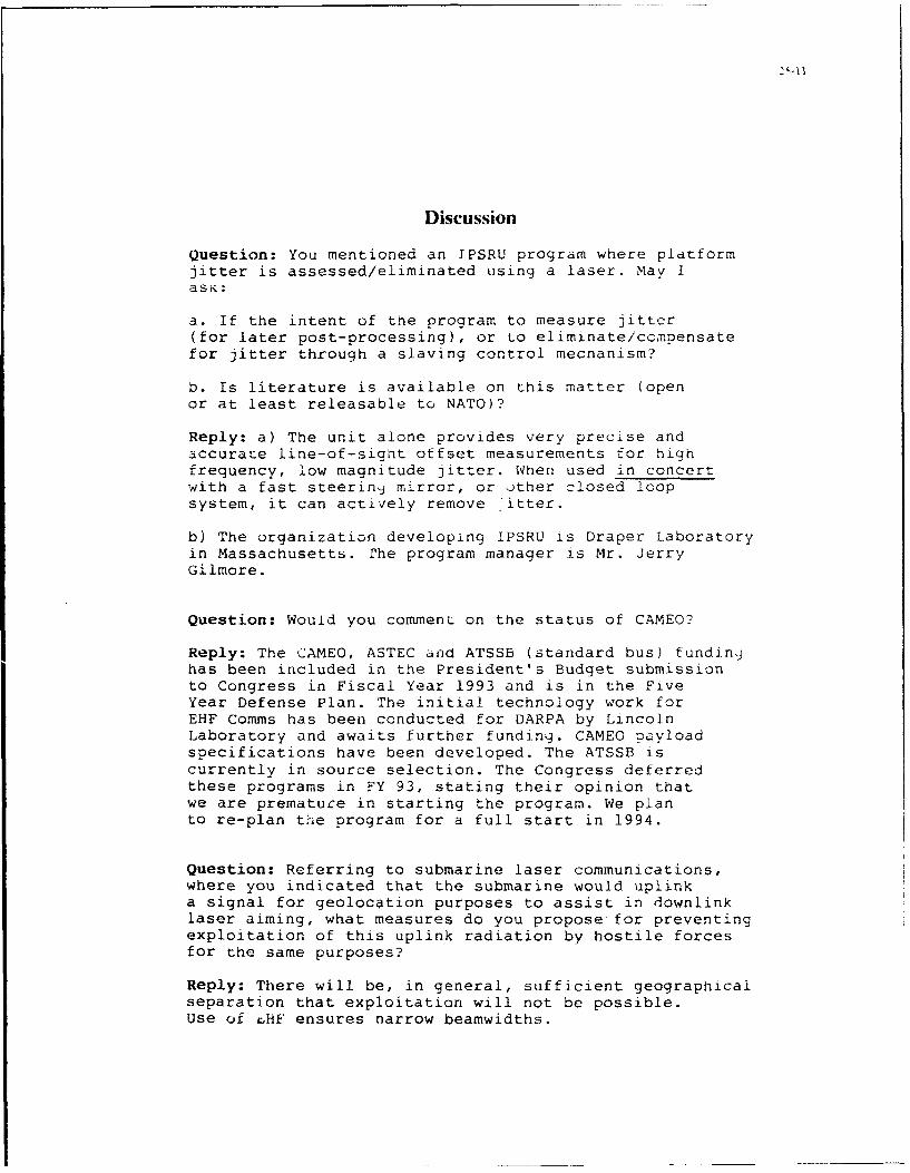
Discussion
Question: You mentioned an JPSRU program where platformjitter is assessed/eliminated using a laser. May IasK:
a. If the intent of the program to measure jitter(for later post-processing), or to eliminate/compensatefor jitter through a slaving control mecnanism?
b. Is literature is available on this matter (openor at least releasable to NATO)?
Reply: a) The unit alone provides very precise andaccurate line-of-sight offset measurements for highfrequency, low magnitude jitter. When used in concertwith a fast steerin•j mirror, or other closed loopsystem, it can actively remove -itter.
b) The organization developing IPSRU is Draper Laboratoryin Massachusetts. rhe program manager is Mr. JerryGilmore.
Question: Would you commenL on the status of CAMEO?
Reply: The CAMEO, ASTEC afnd ATSSB (standard bus) fundingjhas been included in the President's Budget submissionto Congress in Fiscal Year 1993 and is in the FiveYear Defense Plan. The initial technology work forEHF Comms has been conducted for DARPA by LincolnLaboratory and awaits further funding. CAMEO payloadspecifications have been developed. The ATSSB iscurrently in source selection. The Congress deferredthese programs in FY 93, stating their opinion thatwe are premature in starting the program. We planto re-plan ti-ie program for a full start in 1994.
Question: Referring to submarine laser communications,where you indicated that the submarine would uplinka signal for geolocation purposes to assist in downlinklaser aiming, what measures do you propose for preventingexploitation of this uplink radiation by hostile forcesfor the same purposes?
Reply: There will be, in general, sufficient geographicalseparation that exploitation will not be possible.Use of rHF ensures narrow beamwidths.
SAR SENSORS ON TACSATS:A FEASIBILITY ASSESSMENT
G. PerrottaAlenia Spazio S.p.A.
Via Saccomuro 24, 00131 Rome, Italy
SUMMARY
The feasibility of installing SARs on 2. SAR OBSERVATION MISSIONSboard lightsats for tactical and strategicobservation missions is discussed, SAR sensors operational value comes fromemphasizing high resolution and short their independence from time of the dayrevisit intervals as main system drivers, and clouds cover. Achievanle groundLightsat constellations design criteria resolutions, swaths and access angles areare presented for both global and limited comparable to those ot panchromaticlatitude belt coverage. Pros and cons of optical sensors. Nevertheless SARs respondsunsynchronous versus medium inclination differently to the physical features ofnon sunsynchronous orbits are discussed, the observed scene: this may be exploited
to enhance certain target characteristics.Gross system trade offs for the SAR sensor SAR and optical satellites can thereforeare then addressed, in the specific complement each other.context of a resource-limited lightsat,stressing the achievement of resolutions However, in a tactical scenario, wherebetter than 5 m, swaths greater than 20 weather and time-of-day independence ofKm, access angles of at least 30', small the observations are a premium factor, SARantenna dimensions and a reasonable power satellites outperform the optical onesconsumption. Both X and C band SAR from an operational viewpoint.solutions are outlined. Data transmissionalternatives are also discussed, in the In addition, constellations ot SARcontext of tactical and strategic satellites can offer performancescenarios, outlining their projected unmatched by larger spacecraft flownperformance. individually, such as inherent redundancy,
more frequent revisits and an easierConstellation orbits control and platform access to in-orbit resources. If SARattitude are also addressed for their sensors can be flown on lightsats theimpact on mission , SAR image quality and total system cost can be considerablysatellite design requirements. Key aspects reduced, while achieving more flexibilityof critical platform subsystems are also in deploying and managing them.identified.
1. INTRODUCTION 2.1. System configuration alternatives
We will discuss representative missionsLightsat constellations are receiving stressing the hi-resolution ones forconsiderable attention by industry, defense applications. SAR lightsats can begovernmental Agencies and commercial launchea on-demand, for short durationcarriers. Their potential for strategic observation tasks over specific areas, incommunications is well understood by the event of geo-political or militarymilitary planners, which contributed to crises. Alternatively, long durationthe fast spinoff of major projects being missions with lightsats constellations canundertaken by some American system houses. be envisaged to perform continuousLess well perceived are the lightsats observations within a given latitudecapabilities for remote sensing and belt.observation tasks for both civil anddefense uses. In 1990 , anticipating the The cost-effectiveness of short durationneed for new and unconventional solutions missions is nevertheless questionable,to observation satellites, Alenia Spazio considering the need for a permanentstarted an internal study addressing the ground infrastructure which has to befeasibility of small SAR satellites, operated and maintained anyway, and thestressing the achievement of high satellite and launch costs which areresolutions and short revisit intervals, poorly amortized. Permanent constellationsThe '91 Gulf War provided further stimuli can, instead, offer even better globalin that direction, reinforced by the performance at a higher initial cost whichworld-wide trend concerning space and is however amortized over a much longerdefence budget allocations. First results service period. Furthermore, a permanentwere published in (1]. Since then, further constellation can provide shorter revisitwork on system architectures and trade intervals and, outside crises periods,offs has been performed, concentrating on strategic observation services as well asmilitary applications and the near-term remote sensing functions for governmentfeasibility with available technologies, and public use, with specific reference tothus avoiding long and costly new post-disaster damage assessment. We willdevelopments. This paper reviews some of thus concentrate, in the following, onthe most recent results achieved so far. lightsat constellations.

26-2
2.2. Requirements overview 3.1.1. Lightsat Constellations with one-antenna SA~s
An increasingly important requirementconcerns the revisit interval with which The capvbility of a SAR to image targetmilitary relevant sites must be observed: areas inside a wide earth strip istypical values from few days to 24 hours proportional to the access angle, definedapply mainly to fixed assets. Observing by the minimum and maximum SAR off-nadirtargets variable in time or space angles. The constellation design criteriarequires, however, much shorter revisit should provide for a contiguous earthintervals, of the order of few hours. coverage, within the above constraints. ToConcerning ground resolution, 5 m are this end, the fundamental interval issufficient for detection, and in some divided into N subintervals whose widthcases recognition, of strategically corresponds to the SAR antenna accessrelevant fixed or low-mobility assets. angle projected onto the equator. if theTactical applications need, however, minimum and maximum off-nadir anglesbetter resolutions down to 2 m or less. satisfy the constraints ot Fig. 3.1,1.,
then the strips accessible to the NThe swath width , or instantaneous field satellites will be contiguous.of view, must be commensurate to thetheater: 20 to 40 Km , depending from the Fig. 3.1.1. SYSTEM GEOMETRYground resolution, are likely values. Theswath must also be electronicallyrepositioned inside the access angle, satel.iteproviding a high operational flexibilityin gathering SAR images of selected spotsduring satellites' overpasses. Wide access left antenna right antennaangles are instrumental to secure acoverage without 'holes' and to minimize access angle access anglethe constellation's satellites number. b b
Time delay minimization between a requestfor data and its availability to the end-user is of utmost importance, specially in a aa tactical situation. Direct access to thesatellites, during sites overpasses,followed by lccal data processing andinterpretation by multiple data stationsdeployed in the theater, are seen as aneffective answer to such needs.
In a strategic scenario there is the eradditional requirement of being able to earthobserve distant sites with a shortturnaround time. Relaying imagery data viaa Data Relay Satellite network is the mostlogical and performant solution to the In one orbit period, the N satellites willproblem. have covered an Earth slice as wide as the
fundamental interval, and the cycle willrepeat providing a continuous Earthcoverage up to a latitude close to thesunsynchronous orbit inclination.
With the constraint of keeping theminimum and maximum off-nadir angles close3. CONSTELLATIONS DESIGN CRITERIA to 20" and 50" respectively, the number ofsatellites N depends from the orbitWe must distinguish between systems aimed altitude and access angle, as shown in
at providing a global Earth coverage and Fig.3.1.2. and Table 3,1.1.those intended to cover a narrowerlatitude belt around the equator.
, ,00As a matter of fact, most Countries wherepolitical instability is expected to occuralso in future are included in the 50' Nto 50" S latitude belt: which may justifytailored constellations. Fig 3 1 2 N-bero a t a |It*11 * a -bit *IttU.e
.14,h ,on.,.ln,. on O!.-I edil *-91..3.1. Constellations for global coverage
10A modular solution consists in injecting Nequispaced lightsats in single plane sun- ÷ 4.synchronous orbits; the SAR can be .oprovided with just one or two antennas .20 - l oU,.dt, *"0.looking on both sides of the flight path.Multiple equispaced orbital planes can N N•=0*, o, *,,*I,,t.cope with very stringent revisit intervalrequirements, i.e. less than 12 hours. 300 400 400 600 700
0,0,, *tstl,,4. 6R
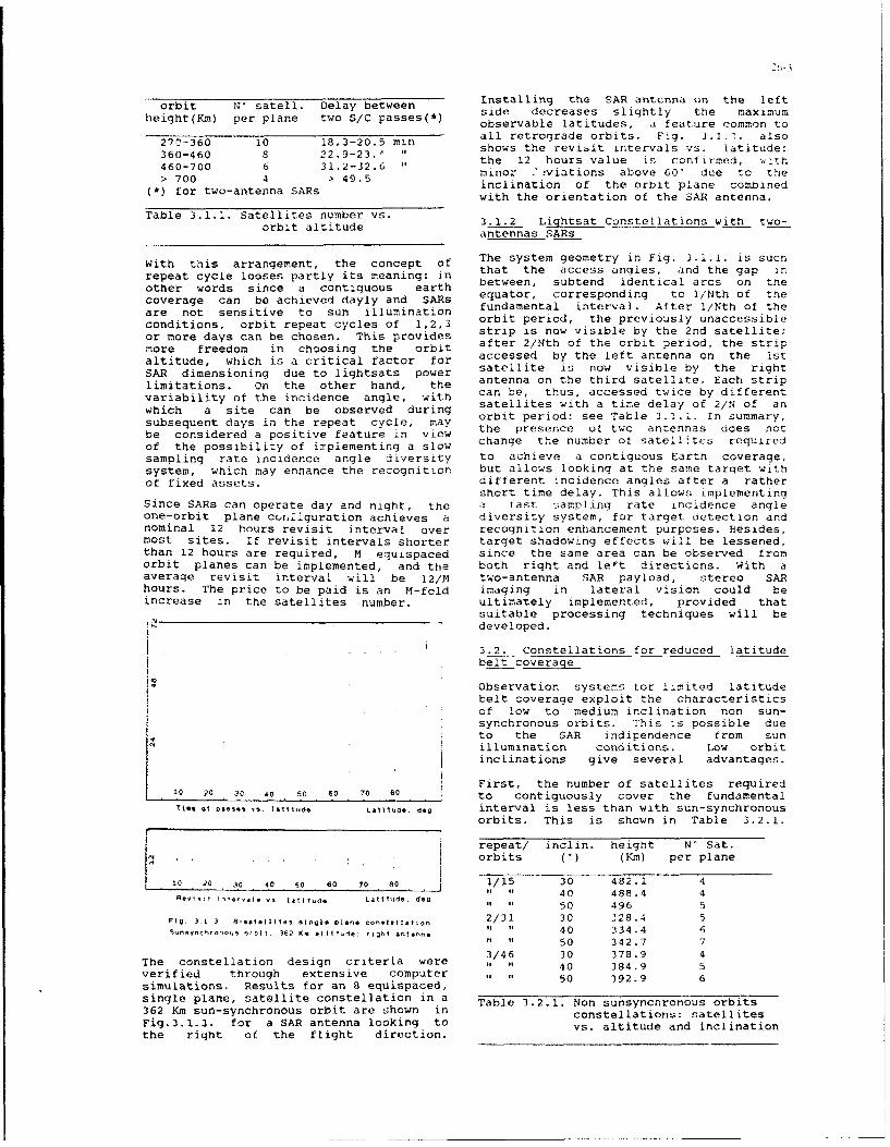
orbit N' satell. Delay between Installing the SAR antcnna on the leftheight(Km) per plane two S/C passes(*) side decreases slightly the maximum
observable latitudes, a feature common to
27'-360 10 18.3-20.5 min all retrograde orbits. Fig. 3.1.7. also
360-460 8 22.9-23.1 " shows the revisit intervals vs. latitude:
460-700 6 31.2-32.6 the 12 hours value is confirmed, .it h460700 4 41. 2.5 minor - aviations above 60" due to thefor 700 -aten 4inclination of the orbit plane comobined
with the orientation of the SAR antenna.
Table 3.1.1. Satellites number vs. 3.1.2 Lightsat Constellations with two-orbit altitude antennas SARs
With this arrangement, the concept of The system geometry in Fig. 3.1.1. is such
repeat cycle looses partly its meaning: in that the access angles, and the gap in
other words since a contiguous earth between, subtend identical arcs on thecoverage can be achieved dayly and SARs equator, corresponding to I/Nth of theare not sensitive to sun illumination fundamental interval. After 1/Nth of the
conditions, orbit repeat cycles of 1,2,3 orbit period, the previously unaccessible
or more days can be chosen. This provides strip is now visible by the 2nd satellite;
more freedom in choosing the orbit after 2/Nth of the orbit period, the strip
altitude, which is a critical factor for accessed by the left antenna on the istSAR dimensioning due to lightsats power satellite is now visible by the rightlimitations. on the other hand, the antenna on the third satellite. Each strip
variability of the incidence angle, with can be, thus, accessed twice by different
which a site can be observed during satellites with a time delay of 2/N of an
subsequent days in the repeat cycle, may orbit period: see Table 3.1.1. In summary,
be considered a positive feature in view the presence of two antennas does notof the possibility of implementing a slow change the number of satellites requiredsampling rate incidence angle diversity to achieve a contiguous Earth coverage,system, which may enhance the recognition but allows looking at the same target withof fixed assets. different incidence angles after a rather
short time delay. This allows implementingSince SARs can operate day and night, the a fast sampling rate incidence angleone-orbit plane cuEr.1Iguration achieves a diversity system, for target detection andnominal 12 hours revisit interval over recognition enhancement purposes. Besides,most sites. If revisit intervals shorter target shadowing effects will be lessened,than 12 hours are required, M equispaced since the same area can be observed fromorbit planes can be implemented, and the both right and leFt directions. With aaverage revisit interval will be 12/M two-antenna SAR payload, stereo SARhours. The price to be paid is an M-fold imaging in lateral vision could beincrease in the satellites number. ultimately implemented, provided that
suitable processing techniques will bedeveloped.
3.2. Constellations for reduced latitudebelt coverage
Observation systems tor limited latitudebelt coverage exploit the characteristicsof low to medium inclination non sun-synchronous orbits. This is possible dueto the SAR indipendence from sunillumination conditions. Low orbitinclinations give several advantages.
1 2First, the number of satellites required0• 20 30 so 50 60 70 80 to contiguously cover the fundamental
6T(, 01 •-0*, 14111.de, Laiude deg interval is less than with sun-synchronousorbits. This is shown in Table 3.2.1.
repeat/ inclin. height N' Sat.orbits (U) (Kin) per plane
10 20 30 40 -0 60 70 80 1/15 30 482.1 4" . 40 488.4 4" " 50 496 5
Fig 3 1 3 -s, l*.it., .1.01. plan* t#,, tlon 2/31 30 328.4 5Svn~ynchr u otbit )62 Km altitude, ight antenna " 40 334 .4 6
"" 50 342.7 73/46 30 378.9 4
The constellation design criteria were " " 40 384.9 5verified through extensive computer 1 "1 50 392.9 6simulations. Results for an 8 equispaced,single plane, satellite constellation in a Table 3.2.1. Non sunsynchronous orbits362 Km sun-synchronous orbit are shown in constellations: satellitesFig.3.1.3. for a SAR antenna looking to vs. altitude and inclinationthe right of the flight direction.
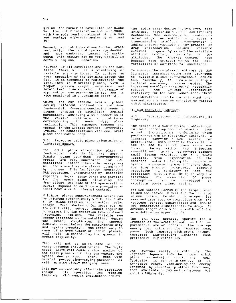
'6-4
giving the number of satellites per plane the solar array design becomes even norevs. the orbit inclination and altitude, critical, requiring a 2-DOF c:un-trackingwith the additional constraint of minimum mechanism. The necessity !or continuousand maximum off-nadir angles of 20" and solar wings reorientation will cause a50". time-changing satellite cross-section
adding another variable to the problem ofSecond, at latitudes close to the orbit drag compensation. Besides, variableinclination the ground tracks are denser external torques may impact the satelliteand move east-west instead of north- attitude control, specially at lowsouth. This feature may be very usefull in altitudes. The thermal control alsocertain regional scenarios, becomes more critical due to the "ul1
variability of environmental conditions.However, if all satellites are in the sameplane there will be a clustering of In summary the complexity and cost of SARrevisits every 24 hours. To achieve an lightsats increases going trom down-duskeven spreading of the revisits trough the to multiple planes sunsynchronous orbitsday, it is essential to redistribute the and, eventually, to single or multiplesatellites in M orbital planes, with a inclined non sunsynchronous orbits. Theproper phasing (right ascension and increased satellite complexity necesarilysatellites' true anomaly). An example of reduces the payload accomodationapplication was presented in [11 and is capability for the same launch mass. Thesealso mentioned in a companion paper [2). considerations must be borne in mind when
evaluating the mission benefits of variousThird, one may combine orbital planes orbit alternatives.having different inclinations and samefundamental. Coverage continuity needs a 4. SAR-CARRYING LIGHTSATSproper phasing of satellites orbital .parameters, achieving also a reduction of 4.1. Capabilities nd !imitations ofthe revisit intervals at latitudes uiqhtsatscorresponding to each orbit planeinclination. This approach reduces the The design of a SAR-cirrying iiahtsat mustspread in the average revisit intervals, 1o11ow a bottom-up apprcan starting irontypical of constellations with one orbit a set ot constraints ind defining whichplane inclination only. performance can Le reasonably achieved. A
lightsat carrying a 2AR sensor for3.3. Impact of orbit plane orientation on professional uses cannot be too small; alightsats design 500 to 800 KN launch mass range was
chosen, being within the injectionThe orbit plane orientation plays a capabilities, in LEO, :f several plannedfundamental role in lightsat design. small launch vehicles. For a 5 yearsSingle plane down-dusk sunsynchronous lifetime, drag compensation ;s theorbits are very convenient for SAR dominant factor in sizing the propulsionsatellites: infact fixed solar arrays may system. A companion paper !3" shows that,be used since they are always illuminated for long mission luraiticns, electricby the sun. This facilitates continuous propulsion ia mandatory to keep theSAR operation, unrestrained by batteries propellant mass within 100 Kg at very lowcapacity. Solar array wings are parallel altitudes. The tssociated DC powerto the orbit plane minimizing the consumption must be considered indrag effect. One side of the spacecraft is satellite power plant sizing.always exposed to cold space providing anideal heat sink for thermal control. The SAR antenna cannot be too large: when
folded and stowed it must fit the limitedMultiple planes sunsynchronous orbits can volume inside the shroud e-•velope; itsbe oriented symmetrically w.r.t. the 6 AM- mass and area must be compatible with the6 PM plane implying sun-tracking solar attitude control capabilities and shouldarrays. Earth shadowing for about 50% of not contribute significantly to drag. Anthe orbit will, anyway, result requiring antenna lenght of 6 m and a width of 1.5 mto support the SAR operation from on-board were defined as upper bounds.batteries. Besides, the variable sunvector incidence on the satellite, during The SAR will normally operate for athe orbit, complicates the thermal fraction of the orbit period, so that twocontrol. Nevertheless the sunsynchronicity parameters are of cancern: the averageand system symmetry , the latter only in energy per orbit and the required peakcase of an even number of orbit planes, power. Both increase with orbit height,will help in controlling the growth in therefore SAR-carrying lightsats mustsystem complexity. preferably fly rather low.
This will not be so in case of non-sunsynchronous inclined orbits. The daylynodal shift will cause a slow motion of rhe average energy callectel by 'hethe orbit plane w.r.t. the sun vector. The lightsat depends from the chosen orbitsystem design must, then, cope with plane orientation w.r.t the suL.orbital period time-varying phenomena as Typically, it can be in the 0.7 to 1.8well as with slowly changing ones. KWh/orbit range. Considering the energy
consumed by essential platform functions,This may considerably affect the satellite that available to payload is between 0.5design, SAR operation and mission and 1.3 KWh/orbit.planning. With medium inclination orbits,

For a typical 20% operating duty, a SAiR DC Besides these qualitative ,mnsiderationspeak power consumption of 1.5 to 4 KW more precise limits ,ire _;et by nothcould be fitted from pure energy regulatory and lightmats ..ccommodationconsiderations. Nevertheless, this would restrz nts. The upper value impacts theimply to rely heavily on batteries. More transverse antenna dimensions, as shown inconservatively, a DC power to SAR Fig.4.2.1. showing the antenna width vs.allocation in the 0.5 to 1.5 KW range was the maximum off-nadir angle, operatingretained for system trade-offs. Concerning frequency and spacecraft altitude todata rates, an upper technology bound of swath ratio H/Sw.200 Mbit/sec. was also assumed. In view ofthe above, a SAR payload mass allocation -1in the 150 to 250 Kg range results, for a500 to 800 Kq spacecraft launch massranne.
4.2. SAR SENSORS FOR LIGHTSATS
We review the main trade-offs impactingthe SAR design in presence of constraints.The SAR will normally operate in theSTRIPMAP mode: the swath will beelectronically repositioned, inside theaccess angle, by beam steering in theelevation plane only. This opec'ating modewas found to be adequate for the intendedhigh resolution missions, given thelightsats constraints. Other SAR operating • . -modes, such as SCANSAR, are also vailableif required by the mission. .
4.2.1 Image interpretation. ta rt . .characteristics, and_ S/N .- '
For extended targets high resolutionimages interpretation is more related to Fig. 1.2.1. Antenna width vs. frequencypixel size than to radiometric resolution, band, maximum off-nadir angle and H/SwA single look SiN of 5 dB was choscen for ratio.S;.R dimensioning. SAR operating atdifferent frequencies respond differentlyto the physical characteristics of the This Figure shows that, at X-band, a 50Earth surface, in terms of backscatterinq off-nadir angle is both feasible andcoefficient vs. the incidence angle. For ompatible with the assumed antennathe same backscatter coefficients and conpatible ith the asue atioswat with he aerae tansmtto RF constraints even increasing the H/Sw ratioswaath width the average transmitted RF to 20 (e.g. : 11=-100 Km a d S,,,=25 Km)power increases fourfold from S to X band. eg .. d.Nevertheless the avorage backscatter from At C-band, one has to superiorly limit thetypical ground surfaces also increase by 6 maximum off-nadir angle to about 40',dB from S to X band, so that the twoeffects compensate and it could be loosing in coverage; alternatively a
possible, in principle, to transmit the maximum H,5w ratio of about 12 could be
same power at both bands. For discrete chosen implying however an altitude or
targets, however, the determining factor only 300 Km tor a 25 Km swath.is the contrast ratio against the speckled S-band antennas can hardly be accomodatedclutter The relative merits of X vs. S on lightsats at all otf-nadir angles andband are still unresolved due to the large orbit heights.variety of possible scenarios and thescarcity of experimental data at X band.Assumimg frequency independent targetRadar Cross Sections, the SAR should bedesigned for the same S/N indipendentlyfrom frequency. This criterion results inan increase of the transmitted RF powerwith the operating fiaquency, penalizingthe X-band choice. In the followingreference is made to a sigma-nought of -15 •"'" .,*0.dB independent from frequency and off- -,• ....radir angles.
4.2.2. Freu choice, ,,.ss angle, i ,...and resolution
In sizing the SAR access angle, too low oooff-nadir angle values should be avoided, *'.. a .-. ,.. ',.O
not to look at targets with near verticalincidence. Too large values should also beavoided to reuuce shadowing effects and Fig. 4.2.2. Chirp bandwidth vs. rangeexcessivc image distorsions. resolution and off-nadir angle.

T-6
The lower bound of the off-nadir angle is
determined by the SAR chirp bandwidth, as
shown In Fig.4.2.2. for range resolutionsbetween 2 and 5 m.
.,60 K.
The instantaneous SAR bandwidth must becompatible with international bandwidth 450
allocations for Radar systems operating in ithe various frequency bands. It turns outthat, considering the 100 Mhz bandwidthallocation for C-band space radars, a 5 m. * :5irange resolution limit must be a..cepted, .-or a severe restriction in the minimum -,offnadir angle to about 40' would result,impacting negatively the coverage or the . - -
number of satellites in the constellation. :* 20 '0
On the other hand, a 2 m range resolution -_ __
at 20" minimum offnadir angle is • "compatible with both X and S-band choicis,since bandwiths of respectively 300 and200 MHz are available for this service.
Azimuth resolution, in the SAR stripmap Fig. 4.2.3. Average transmitted RF power
mode, depends from antenna lenght and Vs. swath width, azimuth resolution ano
looks number. It is between 2 and 3 m for pulse lenght.
antc'nna lenghts in the 4-6 m range, with 1look. The situation is summarized in Table4.2.1. ahich identifies two possiblesystem alternatives:- a medium-high resolution C-band SAR forconstellations in low to medium altitude ":, •
orbits; 0% -
- a high resolution X-band SAR, forconstellations in medium altitude orbits.The S-band alternative is rejected beingincompatible with typical lightsat . 300 :0i"
accommodation constraints. /
Freq. Avail. Range Azim. Maximum 04250band BW resol. resol. H/Sw 4 " "
(MHz) (m) (m) (*) /,
S 200 2 2-3 '.20
C <100 5 2-3 < 12 i200 "X 300 2 2-3 not compatib. _ /
(*) at 50* off-nadir, Nlooks=1 /".
Table 4.2.1. Impact of frequency band and -.150
lightsats constraints on SAR 10 20 30 40fcasibility . ...
Swath wtdth, Ka
4.2.3 X-band SAR: Swath,•data rates, andRFpower Fig. 4.2.4. Data rate vs. swath width,
azimuth resolution and pulse lenght.
This section focuses on X band SAR trade- Orbit height: 360 Ym; off-nadir angle: 50,
offs. The swath, off-nadir angles,resolution, pulse lenght, orbit height,and average RF power are closelyinterrelated.
Fig. 4.2.4. shows how the data rate variesAt a medium altitude of 360 Km and maximum with swath and ground resolution, issumingoff-nadir angle of 501, achievable swaths to trat 4 bits/sale, is feltand average RF powers VS. ground to transmit 4 bits/sample, , ., is feltresolution and pulse nh pwound to be adequate for most tactical SARFig. 4.2l . Increasing the pulse lenght imaging applications. The data rate
Fi. 423 nraigteplelnh increases with swath and even more rapidly
one looses in swath width but peak powers with ground resolution, and is therefore a
decrease too. More specifically for pulse limiting factor for such satellitelenght greater than 20 microsec. peak syts. heaumd20bise uprPowers below 1 KW are feasible, while systems. The assumed 200 Mbit/sec upperpelowers below 1 arefeaible, whilo peak bound is compatible with a 20 Km swath atbelow 15 microseconds multikilowatt peak 2 m resolution, or a 35 Km swath at 2.5 mpower levels result, impacting HPA resolution. Lower data rates would implytechnology choice and reliability, narrower swaths, and viceversa.

Teaverage RE' power increases also with De t h prueae .grseorbit altitude, see Table 1.2.2. about .I:' ,ninmurolnir ag
________ ____ ~limited bemsa dflq fl the -'.t1!pal
Citalt-. t;3wa-th dt(K)re'ltenm an be also mpiemenred t:- ua 1 ze tne~Km) 40/3 3012.5 5 2 . t6 antenna qain throuan the c. idth. ii(I
7- -____ -- igher -heaialepes .;utasidc!..: i
6-5 .8 4.. -~.. I iprove range amn-iquzv c..nr.360 s4.6t 81 8 .1. articu iarly important i
460 1033 104 inqiens. uesides, nI rpi .s r Epp~r.5oO 123 38. 3 requ Ires putt i ng i cam c1 trar.
t.,60 i57 143 101_____ ___ chieving ouch features wit' :naoe controi
,aible 4.2.Z. Average transmitted RE' power only (constant anp~itu,.de illum~nationvs. orbit altitude. swath anld tJOIVO preterred to reduce antonrna wicdth atresolution at 50' ott-nadir. -aou rf-naciir 'nqp I a e te .rn
_______ ____ ____ ________ intrivial task, Lai :1: ~ le Ar tx-'and a passive >inailo pol 'rý -it icn o<'siqr%.
This contirms the desire tor tlyinc; SARS -sing 7ult;Qie tr ralat ing"atr rather low altitudes. wioatb' itn ýavequaei s ~1 Ctc -Ier Iiv i Ce rScoverage and revisits goals. Once -,he :ýarrying embedded t' e''~:, can becswath is chosen it 101rept csonstant, raie tric r'c u
independently f rom, its repositioning m. mp, c-r ies iqn , i ,ý:ý*;,,inside the access angle, and so is 1tic ; , to 12 -th. mni 1........ ........peak power bor obvious hardware :scaes . A proratlc 11 ~t er c1nmls n ' ýC: 'n -constraints. However, from 50' to 20' ct- )Ism te implemented ,It I"-- r:.nadir, the antenna beam in the elevaticnplane M usrt be broadened It cover t !e-iwath. As a result the pulse -iuraitian rcast-z.o cýraduall 1y ,rc r ea s ed to ccvr c-eambreadeni~no lesses. ?hTo, t. - ita ,a~.,a .i rnadir, the averaae trano-ittea :, 2-e icsr t ic- :J1t,;ell as the absorned FDC sewer, is !ccst 1:w; cms ere :n -rridr' :. "1i 1 ir,
1.atimes that at 50 -,t t -nad ir. ip prs 1C ne s ýOre ccn!-.idere :1 Iroc-1 da ta-tranl3miS;oicn taý ý7 :....... -1,e ft data
;ther ;ýAR modeds can he -ýmplerentej reay jatellite~s, cr taa.t
according to mission needs, trading zuA s ubeunt aata 'Jump w is '.-z: nsonideredgeometric with radiemetric resolutions .;ract Ca: a 'nd ,lcto:ve t LO u e t 0(multi-look modes), or a:.-muth resolutiol exp~cted near-term technoicr': .;m~itatiatls.with swath widths f SCA3ISAR :-ode),_ -rra n ce resolution w ith ivera~ne rOW "r, - 'A T1 ýý .
adapt ive Iy changing the -h irL c aclwdtn.- -
and peak Duise sawer vij or wac 1 h c~ct;'rn-h prlP ra t lan . 7"C'.r !nacecrat t It' :n wa Zt tajt III" -V1r't c, v ~.jeternined by the meast mca nd~n rete nieo trni men r:r;iitablC whenresolution t ancks. !ejam.'i R -sra s':Or IteS too
.a r inart : rcm the da t a ýa t ic nC-bandSAR tIcade-otfs results
'n a tactical isccnars.o =wevkr, a!PposlnOlParametric evaluations were also performed 10 rece a re r crm.a I I .:eni p1c,", w;ithin ait C-band, achieving similar results :n.1 circle I lw hunares 7 .~ - Ri--d-Dat atelrra ot swath widths, which are anyway~ :-cce i v- n -; t at nMS ! p5; ol n Cr
:cuper ior ly 1 im it ed by t he a n te nna ";I d th -ýa 70, th-e tnleairor!
the ua~te ll te,- ci ito ca . ion during
substantially lower RE' average transmitted D,,e rp as se s i ad AatŽi-'~. ta 1tarpowers, as well as DC power requirements, imme i ate, sn-site, ral poesig
-Are needed consistently with the lower Table 5.1.1. suMm a r i zes tne projected
range resolution feasible at C-band. A characteristics or I direct trasmissionSCANSAR mode would equalize the azimuth system at X-band.and range resolutions wh il1e nearly _________
doubling the width of the imaged groand Satellite terminal
strip w.r.t. a hi-resolutlmfl X-band -Frequency: e G11zimplementation. In this way a simple -Antenna: mechanical steerin-, driven ti,medium resolution SAR could he implemented on-boasr :,i-it", tOM'
for wide area surveillance tasks. -EIRI, riB`13 (A"nt. :-1i.n:.
4.2.4. SAR antenna reauirements - ata rate: up to 1200 "bit. se.::-Medul./cedinq:a; ýg, OP ;' ,4 3 coding gain;
A phased array with electronic sicanning in -Mass and DC pow-r: 10 Eli, 2the elevation plane will position the **Receiving Stationswath within the access anl Bfesides Antenna: transportable, -with tracking;nrovidinq beam stoerinq in a '-l -. r~t. - /T: Is dB/K- (Ant. sar1.: '.85
also provide Leambroadenini in the -System margin:' 3 dB"ilevat- n plane to match antenna beamwmdthto the swath position inside the access Table .. Dirert I'Ata tn iSsltoangle. ground: ,.yst,,; prtoirmance,

'64S
For a single plane sun-synchronous orbit 6. PLATFORRM DESIGN kFQUIVEMENTSconstellation, meeting the design criteriadiscussed in 3.1.1.. the accessible area To complete this ovurview on lightsatfrom the satellite passes in visibility of constellations, the satellites controla data receiving station has been aspects and the main platform designparametrically evaluated for a minimum considerations Ire addressed in theelevation angle above the horizon of 5'. following.It must be noted that the abtve area canbe accessed two times per day and per 6.1 Orbit controlorbit plane: multiple orbital planesconstellations will increase the dayly Accurate orbit controi ii; important :ornumber of such 'events'. Table 5.1.2. two reasons:shows the number of usefull satellitepasses and tctal accessible area vs. orbit - to take images of specific targets, whenaltitude. The total available access time the satellite is not directly visible fromis between 2500 to 3100 sec., pe' 'event', ground, according to preloaded time-during which 500 to 600 images typically related instructions. Concerning this30 by 30 km wide, could be made available point a positional error contribution ofto the data station. Such values may, up to 0.3 to 0.5 Km could be tolerated,obviously, be reduced due to real-time which will decrease the effective imagedground processing limitations, area by less than 5 percent. Accurate
orbit keeping, in presence of drag andOrbit Number of Accessible Total other external forces, is mandatory to
altitude satellite area access avoid coverage gaps due to differential(Kim) passes (10-6 Km-2) time(s) lags between sate!llites of the
constollation, and may be implemented with268 10 4.9 2500362 9 7.6 to electrical prop'.lsion on long duration460 7 9.8 3100 missions. Orbit keeping in a tight
altitude deadband requires thrustTable 5.1.2. Direct transmission to ground modulation which will benefit from the
mission related performance presence of an autonomous navigationsystem. However long lifetime operationof electric thrusters has to be
5.2. Data transmission via Data Relj• demonstrated.Satellites -To support removal of satellite orbitalFor strategic observations over sites not position related errors during groundin direct visibility of ground stations, image processing. For high resolution X-the use of a DRS network will be a cost- band SAR imaging, the tolerable error ineffective and performant solution. Our the orbit position estimate is in thestudies have shown that , in view of the range of 300 m, above which SAR imagingsevere lightsats volume and mass degradations will occur.limitations, Inter-Orbit Links shouldpreferably be carried out at 60 GHz. Implementing I GFS-based autonomousEfficient coding schemes providing > 4 dB navigation syste may achieve a real-timecoding gain must also be used to further three dimensional orbital positiondecrease antenna size and power restitution with 100 to 200 m accuracy,requirements on both user terminal and thus meeting the above requirements,Data Relay Satellite. The DRS repeaterwill feature onboard uamodulation- 6.2 Attitude controlremodulation, while decoding is performedon ground. Spacecraft attitude control impacts two
performance:Table 5.2.1. outlines the key
characteristics of a DRS transmission - the accuracy with which the swath can besystem based on 60 GHz user-to-DRS links positioned inside the access angle;and the 20 GHz band for DRS-to-groundlinks. - the quality of SAR images after ground
** Satellite terminal: processing.
- Frequency: 60 GHz band It is important to distinguish between- EIRP: 57.5 dBW (1.5" ant.diam.; attitude control and attitude restitution.
10 W Ty pwr) With SAR electronic beam repointing,- Mod./coding: QPSK/ >4 dB coding gain; satellite attitude errors in roll affect- Data rate: up to 200 Mbit/sec.; mainly the swath positioning and can be- Mass and DC power: 15 Kg, 70 W partly corrected if the roll attitide is** DRS payload: known with a better accuracy than the- Frequencies: 60 GHz Rx; 20 GHz Tx; spacecraft attutude control. Yaw and pitch- G/T: 33 dB (2.1 m ant.diam. at 60 GHz); attitude errors impact the image quality- EIRP: 56 dBW (I m Tx ant.); and must be strictly controlled. If their** Data Station: restitution is known with an accuracy 3 to- G/T : 27 dB/K" (12" ant.diam.); 5 times better than their control, error- Slant range: to synchronous orbit; removal during ground processing will be- System margin: > 8 dB easier. Under these assumptions, a 0.1'
attitude error in roll control and lessTable 5.2.1. Data transfer to ground via than 0.08" in pitch and yaw control can be
Data Relay Satellites set as reasonable goals.

Nevertheless high frequency attitude error 7. CONCLUSIONScomponents, as might be induced byflexible appendages subjected to transient Lightsats in the 00 to u00 Kq range c.Anforces, must be minimized due to the bad carry SAR sensors tor h~qh, resolution 2effect they may have on image quality, to 3 m), short revisit ,nterval, tactical
observation missions. Medium resolution6.)3Spacecraft platform requirements (order of 5 m) missions, for strategic
and, in general, international law-We outline some platform subsystems design enforcement applications, are alsoaspects most relevant to SAP performance feasible. Such spacecraft can formand operation. permanent constellations ot, typically, 6
to 8 satellites per orbit plane to provideLow orbit altitudes will require electric global coverage. Multiple orbit planespropulsion, which must be considered an constellations can offer enhancedenabling technology [3] for these SAR performance, 0llowino also a gradual
lightsats missions, as already discussed, system build-up. Smaller constellationsNevertheless, flying satellites at low of 4 to 6 spacecratt can be a.wsaltitude has also positive effects, in implemented to cover a narrower latitudeparticular concerning the more benign belt around the equator, wnileenvironment [5]. significantly improving the average
revisit intervals at sites -!or to thieThe structure design, departing from orbits inclinations.conventional, should adopt a highlyintegrated approach where a truss frame In summary, SAR liahtsats constellationsutilizes important SAR payload components, can offer certain performance unmatched bylike the antenna or big boxes, as part of existing, or planned, ;ingle and largerthe structure itself, in order to save observaticn -atell~tes ind can provide amass. Since the bulk of the heat is -aluable cnswer oc •pec•:tc coeraticnalproduced by the SAR HPA, neat rejection :ilitary needs n both aactacai nshould be by direct radiation to space i s trateqlc :;cenarzon. he requiresfar as practical: this is certainly e:asier technologies exict, ,i1th :sw exceptionson down-dusk orbits, needing an early in-orbit demonstration ot
devices being now developed. :Eevertheless,The solar array design is strongly advances 1.I tow :ields will certainlydependent upon the SAR payload operating benefit future generation lightsats.duty. Infact, since the SAR will normallyoperate for short intervals totalling 5 to10 % of the orbit period, payload supply REFERENCEScan normally be from battery, the solararray serving mainly for battery [ G; 5. Perrotta ' 7AR censors on boardrecharging. The orbit plane choice, and small satellites: problems andthe percentage of time spent in Earth- prospectives": Proceedings of 1991shadow per orbit period, will also impact International Conference on Radar; Octoberthe solar array sizing to provide the 1991, Beijing, china;required energy. Besides, electricpropulsion DC power requirements, will [2] F. Borrini " The Italian approach toalso increase the solar array sizing. tactical use of space": this Conference;Accordingly, the solar array type mayrange from a fixed wings configuration, 3[ G. Perrotta, G. Cirri, G. Mitticarisuitable for satellites in sunsynchronous Electric propulsicn tor lightsats: adown-dusk orbits, to a sun-tracking review of applica ions and advantages";configuration for spacecraft in low to this Conterence;medium inclination orbits.
I41 D. Casey, J. Way ' Orbit selection forOr, the above groundz, long lifetime the EOS mission and its synergismoperation of mass-efficient batteries, implications": IEEE Transactions onsubjected to rather deep and periodic (up Geoscience and Remote Sensing; Vol 29 nto 30000) discharge-recharge cycles is an 6, Nov. '91.oustanding issue for such L.E.o.observation lightsats equipped with SAR ý5] H.J.Schodel,T.Kutscheid " The X-bandsensors. CFRP waveguide antenna for the Space Radar
Lab."; ESA Workshop on Antenna Technology,Spacecraft telecommand must be secure, and Nov. 1898.possibly jam-proof, to avoid unauthorizedentries to the satellite system. Dataencryption must be also implemented, inspacecraft telemetry and SAR datatransmission to ground, to preventeavesdropping by unauthorized users.

A TACSAT SAR Concept together with the detection of groundmoving targets has been demonstrated to
C.D. Hall CJ. Baker afford an extremely valuable MilitaryMMS-UK Ltd DRA-Malvern capability. As a consequence there is
Anchorage Road St Andrews Road continued development of these systemsPoRt oad StMAndews Rotogether with refinements in theirPortsmouth Malvern operational deployment and usage.
Hampshire P03 5PU Worcs. WR14 3PS However, a number of restrictions exist inUnited Kingdom United Kinadom the deployment of these systems
associated with their maximum operatingrange. The maximum operating range is
G.E. Keyte and L.M. Murphy governed by the height at which theDRA-Farnborough platform can flv, so for example a radar
Farnborough on an aircraft with a ceiling height ofHampshire GU 14 6TD 30,000 feet will only be able to operate
out to about 250 Km before grazingUnited Kingdom incidence is reached. This limitation can
Abstract be removed by placing the sensor in aspace-based platform. In order tomaximise the military utility of theThe pay'load concept covered by this information produced by the instrument
paper is that of a low cost, high and to allow recognition of targets, aperformance radar sensor capable of design goal of Im has been assumed fordetecting and recognising static objects spatial resolution.within an imaged scene of the Earth'ssurface using the Synthetic Aperture The potential advantages of extensive.Radar (SAR) technique . The overall unrestricted fields of view afforded bysystem is integrated with a TACSAT space based sensors makes then extremelyplatform in Low Earth Orbit (LEO) and, attractive for wide area Militaryalthough only passing reference is made surveillance and hence worthy of furtherto this feature in the paper, the radar attention, particularly with a view tocould also have a capability for the replacing airborne systems (although itdetection of Ground Moving Targets should be recognised that there are a(GMTI). number of inherent technical difficultiesThe paper provides a parametric review in designing a spaceborne system that hasof such a sensor in the light of the target similar sensor capabilities).and background features to be observed. Large areas of the Earth's surface can beA design concept is included showing the observed on a periodic basis and morepossible hardware realisation of a detailed information may be obtained bycandidate system. as well as budgets for dwelling on selected areas. Radar also hasthe mass, size, power and pointing the added advantage of all weatherrequirements of the instrument, day/night operation. Recently imagingAdditional design features considered are radars (SAP) have begun to demonstratethe influence that short duration missions the capability achievable frommay have on hardware redundancy and space-based systems but use relativelythe effect of short, low duty-cycle heavy platforms (eg ERS-1 weighs 1275observation periods on solar array and Kg although it contains 4 other sensors asbattery sizing. well as the SAR) and hence require large
and costly launch systems andThe paper concludes by pointing the way infra-structures. Further they havetowards a low cost R and D demonstrator relatively poor resolutions (eg ERS-1 issystem allowing a practical investigation approximately 30m) making themof the key techniques and technologies. unsuitable for most Military applications
and have no inherent capability for theI Introduction detection of ground moving targets.As a result of the recent UK ASTOR It is, however, possible to conceive SARprogramme and the deployment of US sensors for integration with various formssystems such as ISTARS and ASARS, the of small satellite platform and dependingability to combine information derived on the type of platform used to carry thefrom high resolution imaging radars sensor, different options exist for its

27-2
launch. With one option, the satellite Commander has total control over thecould be launched under the control of a satellite so that the satellite will not beMilitary commander from a mobile, made available to provide surveillancelow-cost launch vehicle. With another, the over any region other than this Crisis area.satellite can be launched by a major Depending on the particular operationallaunch vehicle, for instance in conjunction philosophy, satellite control might bewith the launch of a major payload exercised either directly from within themaking use of residual mass capability. Theatre, or remotely using global controlThese options potentially would allow the systems but under the primary control ofsensor to perform both a short term the Theatre Commander.tactical role, including the replacement ofdamaged or destroyed satellites in times Finally, the dedicated nature of theof conflict, and a longer term strategic service proposed for the TACSAT SARrole whose tasks might also include facilitates some interesting departurestraining of users of these highly flexible from the system thinking associated withsystems. global space surveillance concepts: these
departures influence the choice of orbit,The small size and low mass of the the spacecraft bus design, and the basicsatellite and sensor systems considered in sensor design.this paper will result in significant costsavings making the deployment of 2.2 Orbit Parametersconstellations of satellites very muchmore attractive. This has the further The expectation of a Theatre locationadvantage of reducing revisit times and away from the Northern latitudes invitesconsequently providing information not consideration of orbits of a smallerotherwise available from any other inclination than the polar sun-source, and of improving system synchronous orbit which is characteristicsurvivability. In the next section some of of civil remote sensing missions. Inthe options for a sensor concept are particular, if the chosen operatingdescribed. This is followed by a philosophy for the TACSAT SAR is oneconsideration of system aspects and cost of launch-on-demand in time of crisis.and schedule drivers, then the orbit inclination can be chosen to
maximise viewing opportunities over the2 Impacts of a Potential TACSAT SAR crisis area. If, however, the philosophy isMission on Satellite Design one of in-orbit storage then an earlier
decision must be made about inclination2.1 A Potential TACSAT SAR Mission because of the large fuel overhead
involved in effecting changes in orbitThe TACSAT mission is one which is inclination. However, even in this latterassociated with a Theatre conflict where case, it may well be appropriate to set thethe Theatre is defined as being a region inclination of the storage orbit so thatmeasuring some 2000km by 2000km and coverage is optimised for the smallerthe duration of the conflict is anticipated latitude regions. The absence ofas being relatively short, typically of sun-synchronism, consequent on the smallmonths, rather than weeks or years. orbit inclination, will not present aAlthough areas of political and military particular problem to the radar sensorrisk can lie at any latitude, the ending of which is capable of operating as well bythe Cold War suggests that if there were night as by day.to be such a Theatre conflict, then itsoccurrence in the lower latitude regions, In addition, the relatively short durationrather than the more Northerly latitudes, envisaged for a Theatre conflict allowsseenms more likely. serious consideration to be given to orbits
significantly lower than those used forThe mission envisaged for a TACSAT long duration remote sensing missions:SAR is to provide the Theatre these lower orbits, perhaps as low asCommander with a dedicated service 250km, would be suited to a philosophy ofyielding surveillance data only over the launch-on-demand. However, althoughcrisis area. In this paper, the dedicated particularly low orbits are less attractivenature of the TACSAT mission has been for the case of in-orbit storage because oftaken to mean that the Theatre the short life time which results from

'7-3
atmospheric drag, it is possible to to the satellite track. Table 2 illustratesconceive two distinct and attractive the bandwidths commensurate withpatterns of use for a TACSAT using the resolutions for a variety of grazing angles.philosophy of in-orbit storage.
The limitations on achievable bandwidthDuring the storage period, the TACSAT are due to the capabilities of waveformcan be used for training purposes as well generators and digitisers and theas for active surveillance service although, dispersion through the transmit andat coarser sensitivity. In the event of crisis, receive chains. Current technologythe potential would exist to reduce the imposes a realistic limit of about 1 GHz.orbit altitude in order to improve Unless changes can be agreed, a furthersensitivity over the operational Theatre. It limiting factor will be the currentis important to note however, that such a operating band allocations defined by thereduction in altitude will not bring World Advisory Radio Council (WARC)significant advantages in improved spatial which impose restrictions of 300 MHz atresolution, and the coverage access X-band (9.6GHz) and 600 MHz at J-bandavailable to the satellite at any one pass (13.7GHz). Dispersion in the atmosphereover the Theatre will be more limited and ionosphere is not thought to present athan that achievable from a higher orbit. major problem and, if present, the effects
could be removed using techniques2.3 Duration of Service equivalent to autofocus. Overall it is felt
that a resolution of Im at X band isThe dedicated nature of the surveillance feasible at a 30* grazing angle.required from the satellite means that theperiods during which service is required The synthetic aperture technique isare of short duration. Typically, a satellite employed in the dimension parallel to thein the Low Earth Orbit (LEO) necessary satellite track. This involves the coherentfor SAR operations takes only 5 minutes addition of many pulses to synthesize anto traverse a Theatre measuring 2000km aperture sufficiently long to provide theon the side and with only 2 such passes desired resolution on the ground. Thislikely per day, payload power demands synthesis is only possible if the variation incan readily be met from batteries. The phase path from the sensor to the targetadvantage of this to the platform design is and back is known to a fraction of thethat relatively small solar arrays can then radar wavelength along the syntheticbe used to collect electrical power and aperture. This implies that very accuratetrickle-charge the batteries during the knowledge of the orbital path of theprolonged periods of payload inactivity, satellite is required. However, for
resolutions of the order of Im no2.4 Sensor Design Goals measurement method of the orbit gives
sufficient accuracy in realistic timescales.The design goals for the sensor concept To surmount this problem it is expectedare shown in Table 1. A major difficulty in that autofocus techniques will have to berealising a radar design of this employed. These have the added benefitsophistication is the achievement of such that they will also automatically correcthigh resolutions and in the for other effects which can alter the phaseimplementation of a phased array antenna path length, such as atmospheric,able to operate over such wide ionospheric and gravity perturbations.instantaneous bandwidths.
3 TACSAT SAR Satellite ConceptSynthetic Aperture Radar (SAR) is asideways looking coherent imaging 3.1 Launch Optionstechnique capable of producing map-likeimagery. SAR employs different A wide range of current and plannedprinciples for achieving resolution in the vehicles is available to members oftwo dimensions of the imagery. NATO, optimised for the launch ofConventional high resolution radar satellites with masses as small as 100kgtechniques such as transmitting a and ranging upwards to many tonnes.wideband, long duration pulse and Vehicles such as Pegasus and Scout cancorrectly matching to it on receive are lift the lower end of the TACSAT massemployed in the dimension perpendicular range, around 250kg, into a 500km orbit.

27-4
However, there is a significant gap in accrues from this bus structure is themass-opti nised launch capability such potential for launching several satellitesthat the next available vehicles are San simultaneously from the same launchMarco Scout and Taurus which, when vehicle.developed, will be optimised respectively,for the launch of satellites of 750 kg and The toroidal structure is therefore1200kg into 500km orbit. This gap in capable of providing both an economicalcapability of current launchers means demonstration of the technology throughthat, while there is not a technical a residual-mass launch opportunity, andproblem in launching into LEO, satellites the potential for launch of a fullwhose mass lies at the upper end of the constellation via a dedicated launch -TACSAT range, there could be an without the need for any satellite redesignappreciable cost penalty if Taurus were between demonstrator flight and fullused. Whereas launches on Pegasus and constellation.Scout are priced at $10M and $18Mrespectively, the cost of launching on The outline concept of a SAR mountedTaurus is predicted to be $30M. on such a toroidal platform is presented in
Figure 1. Budgets showing the mass andAn alternative and cheaper approach to power demands likely to be associatedthe heavy TACSAT launch issue is to with such a satellite are presented inmake use of the "residual mass" capability Table 3.often associated with the launch of majorsatellites on large launch vehicles. 3.3 SAR OptionsResidual mass is the mass differencebetween that of major satellite and the Three distinct options of SAR design canmaximum launch mass capability of the be envisaged to provide a tacticalproposed launcher. It is anticipated that capability. In order of rising complexity,satelites will be launched in this way for a these options include, mechanicallycost of $20k - $30k per kilogram, steered systems using a single central highdepending on launch configuration power amplifier (HPA), electronically
steered systems like RADARSAT whichIt is felt that availability and cost are likely use a single central HPA and ferrite phaseto have a major impact on the viability of shifters for beam deflection, andTACSAT concepts so that for the heavier electronically steered systems like theTACSATs, the advantage of a residual European ASAR which use fully activemass launch would be considerable. phased array technology to provideHowever, the penalty that associates with Scansar and Spotlight operating modes.this launch philosophy is thatlaunch-on-demand is not available. Of these fundamental design options, twoTherefore with this concept, the were considered as candidates forFpossibility of designing for short mission discussion in this paper, a partial phasedifetimes is ruled out because the satellite array providing electronic steering only in
must be stored in space perhaps in a the azimuth direction and a fully activehigher long life time orbit so that it can be phased array providing both azimuth andbrought down to operational altitude as elevation steering.and when an appropriate crisis develops. The case of the potentially simpler, partialAs a result of this understanding of the phased array where the elevation steeringrealities which we perceive as constraints is provided only by mechanical pointingon the mission, the SAR concept was considered, but it was concluded thatdescribed in --is paper is based on use of because the time taken to mechanicallythe residual mass launch option. repoint the system would be on the order
of minutes, the number of useful Spotlight3.2 Platform Options imaging opportunities available to the
Theatre Commander would be limited toThe accommodation volume available for a rather small number. When this numbera residual mass launch is basically toroidal is compared with the much larger numberand therefore the bus structure proposed of such opportunities potentially madeas a platform for the SAR is of toroidal available from a fully active phased array,form. An additional benefit which there appeared to be a strong case in

27'-5
favour of the fully active system. from the solar array. For this mission.where many roll manoeuvres are
Thus, although neither of these cases has envisaged and speed is likely to bebeen analysed quantitatively, it is felt that important, the approach comparesthe flexibility of coverage and operating favourably with the use of cold gasmodes which can be derived from active thrusters which provide a finite life to thephased array technology is of such benefit total mission.that its use, even in a small tacticalsatellite, verges on the mandatory. The advantage of this operationalTherefore, the bulk of this paper philosophy is that the manoeuvre enablesconcentrates upon this type of sensor but the SAR to view regions on either side ofacknowledges that designs based on the nadir track. Such an operationalpassive antenna technology of the ERS-l philosophy requires that the wholetype may be able to provide a more satellite including platform, solar arrays,limited capability but at a smaller mass. and SAR antenna, be designed to form a
robust structure with no flimsy3.4 Platform Orientation protrusions.
It is envisaged that during the long 4 TACSAT SAR Sensor Concept andperiods of inactivity between surveillance Performancetasks, the platform orientation will becontrolled in order to provide a benign The paper has investigated the impact ofthermal environment, and that the whole different operating modes and theplatform will be rotated when necessary in fundamental SAR parameters on theorder to provide the appropriate viewing performance achievable for a TACSATangle, and then returned to the benign SAR mission. These parameters include,orientation after the short period of active operating altitude, RF carrier frequency,service, spatial resolution, and possible antenna
structures. However, in order to limit theThe technique envisaged to effect the scope of the paper, all options have beennecessary rotation manoeuvres from based on an assumed antenna area ofbenign to service positions is one of use of 6m 2 . This area is derived fromthe large torques which can be produced considerations of viable payloads forfrom control moment gyros. In this implementation onto a toroidal platformtechnique, a caged system of at least three within the TACSAT mass goal of <gyros is set up and the angular momenta 700kg.of each is established so that the netangular momentum seen outside the cage The detailed performance of a SAR isis zero. However, if a torque imposed described in this section, specifically forfrom outside the gyro cage tries to repoint the single-look capabilities which willthe direction of any of the component characterise its performance in Spotlightangular momenta (the direction of a gyro mode, by parameters which include;rotation axis), then that torque has to beconsiderable and can be used to produce a sensitivity expressed in terms of noisestrong turning moment on the spacecraft. equivalent o0 (NEo Q) and presented
for the worst cases situation which isA difficulty with this philosophy is that the associated with the furthest edge of thevehicle is exposed to a significant thermal available cr verage widthdisturbance during the manoeuvre as aresult of solar illumination. However, the * access coverage width as that distancemanoeuvre can be designed to be of a from nadir beyond which ambiguitiessufficiently short duration that the total rise to an unacceptable leveltemperature excursion may be limited toacceptable bounds. * available swath width for various
operating modesThe advantage of this approach tosatellite rotation movements is that spatial resolution in azimuth andalthough it calls for electrical energy is elevation for various operating modesrequired, such energy can be suppliedindefinitely (via the on-board batteries)

27-6
The operating geometry for a TACSAT are envisaged as providing detection ofSAR is shown in Figure 2 in order to surface targets in motion. The data will beidentify the principal parameters. processed on board so that only the
detections need be down linked back to4.1 Operating Modes the ground data receiving station.
However, it is anticipated that problemsSpotlight with revisiting may lead to difficulties in
interpretation and thus requires furtherIn order to perform a useful research.reconnaissance role, the SAR must becapable of providing images of specifictarget zones such as airfields, harbours, 4.2 Operating Altitude and RF carrierchoke points and railway installations at Frequencythe finest possible resolution. This taskcalls for Spotlight operation in order to Access coverage width is fundamentallyprovide adequate resolution in the limited by system parameters whichalone-track (azimuth) direction and the include; antenna area, slant range toprovision of this capability is a major ground, RF carrier frequency, anddriver in the design of the antenna, satellite velocity - although there is no
significant impact from satellite velocityIn principle, the azimuth scanning which changes but little with altitude. Forassociated with Spotlight operation can be this case in which antenna area has beenprovided by mechanical steering of the constrained to 6m 2 , the dominantantenna. However the difficulties parameters are slant range and RF carrierassociated with repeating such mechanical frequency.steering several times during a single passover the theatre are believed to be so The effect of changes in altitude on accessgreat that electronic steering in the and sensitivity is shown in Figures 3 and 4.azimuth direction is considered to be The data are presented for the case ofessential. operation in Spotlight mode with an
assumed bandwidth of 300MHz. AlthoughSteered SAR this bandwidth is characteristic of the
WARC limit at X-band and is in excess ofIn addition, it is envisaged that a the allocations at S and C, it is nonthelessTACSAT SAR may also be required to interesting to use a single bandwidth inprovide surveillance over a larger region. order to see the fundamental parametricSuch cover can readily be provided in the trends. It is also important to note thatform of a continuous strip-map using the although a mean RF power of 750W isconventional Steered SAR mode which needed to ensure adequate sensitivityhas been characterised by SEASAT, throughout most of the viewing range,ERS-1 and the SIR missions, such high mean powers can be provided
during Spotlight operations by increasingScansar the duty cycle well beyond the few percent
normally used for wider swathIf even wider area coverage is desired, observations. In this way, peak powers inthen the possibility exists of using the the T/R modules can be limited to lessScansar mode which will be demonstrated than 4W.on the RADASAT and ASAR missions.However, provision of a Scansar It can be seen that at the lowercapability relies on the ability to rapidly frequencies, increasing altitude providesredirect the antenna beam in the elevation relatively small improvements in accessdirection: such a capability requires the capability while at the higher frequencies,provision of electronic steering in the substantial improvements can be realised.elevation direction. However, in both cases, increasing
altitude significantly degrades sensitivity.Ground Moving Target Indication The sensitivity data presented in Figure 4(GMTI) show the worst case sensitivity; i.e. at the
furthest distance from nadir for whichIn this mode, which may be combined acceptable ambiguity performance can bewith Scansar, interferometric techniques achieved. Data showing the variation of

"7-7
sensitivity achieved from an altitude of - atmospheric dispersion. This is500km for both C and X band is presented generally, not a problem forin Figure 5. trequencies below X-band, but may
degrade image quality at higherA further impact of increasing altitude frequencies, e.g. around the watercan be seen in Figure 6 where the impact vapour resonance frequency of 22GHz.on the across track component of spatialresolution, range resolution, has been - atmospheric attenuation. This variespresented as a function of distance from with frequency, becoming more acutenadir and operating altitude for a single for frequencies above X-band, possiblyRF chirp bandwidth - 300MHz. ruling out J-band and probably ruling
out Ka-band. However, the attractionSelection of Operating Frequency of the very wide bandwidth allocation
at J-band and the associated potentialIn selecting an RF carrier frequency for a for very fine spatial resolution mayspace-borne high resolution military SAR, mitigate in its favour.several factors must be taken intoaccount. First, it must be noted that, in poorer efficiency of solid state powerprinciple, any ground range resolution can amplifiers at higher operatingbe achieved by provision of a radar frequencies These factors indicate thatemission pulse of adequate bandwidth - X-band is likely to be an optimumtypical examples are shown in Figure 6 for frequency for very high resolutionthe case of 300MHz bandwidth allocation, (around lm)military surveillance SAR,but international agreements constrain with C or possibly S band representingthe bandwidth allocated to space radars as a viable alternative providingindicated in Table 2b. However, although somewhat poorer resolution.such agreements might be breached intimes of crisis, the TACSAT missionconcept also includes peacetime use and 4.3 Imaging Capabilitiesfor this, adherence to bandwidthallocations is essential. For the TACSAT SAR mission
considered in this paper, target imagingThe figures presented in Tables 2a and 2b requirements may be considered to fallindicate that only an X or J band system into the following two main categories;would be capable of providing a groundresolution close to lImi, whilst the use of L, (i) detection and classification of hardC or Ka band would fail to provide a targets, e.g. military vehicles, tanks,ground resolution better than 3m over grounded aircraft, ships, etc.most of the grazing angles of interest. (ii) monitoring and change detection forIn addition to the international distributed targets, e.g. airfields,regulations, other factors affecting the military camps and installations,choice of RF carrier frequency are as harbours, railway yards, chokefollows; points, etc.
- the need for the SAR wavelength to be In the former cases, the targets of interestsignificantly less than the image generally have large radar cross sectionsresolution. This is likely to exclude the relative to the background scene. As ause of L-band (0.23m wavelength) for a result, the ability to detect andsystem aiming to achieve around lm subsequently classify such targets dependsresolution. primarily on the spatial resolution of the
imagery, the system radiometricionospheric dispersio-. This is a performance being relativelyfrequency dependent phenomenon unimportant. A spatial resolution of atwhich can cause a significant least 3m, and ideally less than Im, isdegradation in image quality for considered necessary.frequencies around or below L-band. In the latter case, however, the features of
interest are generally no brighter thanother features in the scene; the key

27-8
requirement for discrimination and case. It is important to note that despiterecognition of such targets is then, good their intended major role as Spotlightradiometric resolution(best SAR speckle imaging sensors, oth of these SARsreduction). This may be achieved by would be capable of providing better thanmulti-looking. The spatial resolution 3m resolution in conventional Steeredrequirement for these types of target is SAR mode.considered less exacting than for "hard"targets at around 5-6m. However, the fact A feature of the active antenna approachthat multi-looking is required implies that which can be exploited in this design is thethe inherent single-look capability be impact on T/R module design whichsimilar to that for hard target detection results from the adoption of Spotlight as(i.e. around 1-3m). the principal operating mode.
The SAR must possess a radiometric When operating in this mode there is aresolution adequate to allow need for the emission of a particularlydiscrimination between adjacent high level of mean RF power in order todistributed features. A sensitivity restore the link budget which is adverselycharacterised by a noise equivalent sigma affected by the increased noise levelzero (NEoo) of -23dB is considered which results from the wide bandwidthnecessary. needed to achieve fine range resolution.
4.4 Antenna Structures Because the region being imaged is only asmall proportion of the maximum, range-
It can be seen from the preceding unambiguous swath, it is possible todiscussion, that the TACSAT antenna increase the transmitter duty cycle andrequires an electronic steering in azimuth provide a several-fold increase in meanin order to provide the Spotlight mode RF power output during Spotliglhtand that a similar capability in the observations. Typically, increases of aelevation direction is highly desirable in factor of 5 can be achieved over thatorder to facilitate the imaging during a normally associated with civil remotesingle pass, of different zones located at sensing missions where the duty cycle isdifferent elevation bearings relative to the limited to around 5%. The advantage ofsatellite, this approach is that these increases can
be achieved without resorting to anThus, the case for electronic steering in increase of the peak RF power handlingboth azimuth and elevation directions capability of the T/R module outputappears to be strong and has led this stages.paper to propose a fully active phasedarray solution for the envisaged TACSAT It is interesting to compare this TACSATmission. mission with a civil remote sensing
mission. In a typical C-band civil mission,The particular aspect ratio assumed for 320 T/R modules operate at up to 8 Wthe antenna is based on the need to peak RF power in order to provide < 150accommodate around the toroidal bus, the W mean RF power, whereas in the6m 2 overall area required to provide the Spotlight TACSAT mission consideredunambiguous access demonstrated in the here, 352 T/R modules operating at 6 Wearlier discussion. Two distinct cases have peak power can are operated to providebeen examined one at C-band, the other up to 750 W mean RF power. In theat X-band. In both cases, the antenna is X-band case considered in this paper, 704built from 11 panels which are assembled T/R modules are operated at less than 3onto the bus as indicated in Figure 1. In W peak power in order to provide thethe C-band case, each panel is populated same mean RF power (750 W).with 32 T/R modules and measures some1300x418mm 2 whereas in the X-band However, the technique is only applicablecase, each panel is populated with 64 T/R to achieving short term gains because themodules and measures some increased transmitter power requires that1400x388mm 2 . Thus, the aspect ratio of the system be capable of handling thethe antenna is similar in both cases being associated increase in waste power. In this4.6m(az) by 1.3m(el) in the C-band case, concept the thermal problem is regardedand 4.27m(az) by 1.4m(el) in the X-band as a thermal impulse and handled by

2-_9
providing a sufficiently long gap between capability can be provided at end of lifeobservations that the long term mean (notionally, 5 years) by 2m 2 of solarpower handling capacity is not exceeded. array, assuming the use of GaAs solar
cells. Moreover, since the operational4.5 DC Power Services concept assumes that during this period,
the whole spacecraft is placed in aIt is envisaged that the TACSAT SAR thermally benign orientation, thiswill operate from batteries during periods orientation can be chosen so that the solarof service and that during sunlight array area can be optimised for smallestspacecraft operation, the batteries will bt. mass by arranging for it to pointcharged from the solar arrays at a rate continuously at the sun.sufficient to maintain them charged, readyfor the next service period. Although the 4.6 Data Down Linkpower demand during periods of service isvery large, the total energy demand is Data Ratemodest and can potentially be satisfiedfrom a low capacity battery, charged from Different data rates can be associatedthe relatively small solar array. with the SAR depending on whether
range compression is conducted on-boardIt is estimated that the surveillance task or on the ground. With the long dutywill place a daily energy demand from the cycles envisaged for use in Spotlightbatteries amounting to only about mode, there is a need to receive radar500watt-hrs. However, the battery must be returns, not only for the duration of thesized not so much to provide the total time delay from near to far sides of theenergy load but rather, to satisfy the 6kW image region, but also for the duration ofpeak power/current demand which is the transmit pulse.needed to energise the SAR and the datadown-link during the 5 second periods The classical technique for reducing SARassociated with each Spotlight down link rates is to accept all the returnsobservation. The demand for low internal from a given single pulse emission into aresistance which results from the large register (during a receive window periodpeak power demand, favours the use of which is much longer than the transmitNiCd batteries rather than NiH7. The pulse period), and then to transmit themass associated with these NiCd bitteries data accumulated in that register duringwill be on the order of 40kg and this the longer period associated with onefigure has been included in the mass pulse repetition interval. However, whenbudget shown in Table 3. the receive window is shorter than the
transmit pulse, there is less opportunityThe total energy demand can be satisfied for data rate compression. If, on the otherfrom a relatively small solar array whose hand, pulse compression is conductedarea is not influenced by the large peak on-board, then the duration of the receivepower demand. It is envisaged that this window - post range compression - isenergy will be collected during the period identical with the time delay between nearof around 22 hours when the SAR is not and far sides of the image region. Thisin a position to observe the Theatre and time difference can be significantlythat during this time a mean power smaller than the interpulse period andcollection rate of only 25 watts averaged appreciable reductions made to the dataover each orbit, will be sufficient to rate.
rovide the SAR/down-link energyudget. Using such techniques, it is possible to
limit the data rate to values as small asHowever, in order to provide power fo: 130 Mbit/s for operations at C-bandthe SAR and the additional 200W power where the SAR chirp bandwidth is limitedestimated as being necessary for the to 100MHz, and to 400Mbit/s forsatellite bus house keeping activities, and operations at X-band where the chirpto account for eclipse periods in the bandwidth is limited to 300MHz. Datacharging cycle, it is estimated that a peak links with these bandwidths exist but thecollecting capability of some 300 watts problems of handling these quantities andshould be allowed at this stage in concept rates of data will require furtherdevelopment. Such a power collection examination.

27-10
Ground Segment Space Segment
The operational concept for the The impact of this type of ground networkTACSAT SAR is that it should make its on the space segment is that the down-linkobservations and almost simultaneously transmitter must be capable of providingtransmit the SAR data to ground for an EIRP of 16dBW froin a smallreception within the Theatre command unsteered antenna. Such an EIRP can becentre where the data will be processed provided from a 120W TWTA assemblyinto an intelligible image. whose total DC power demand is likely to
be around 300W including power to theIt is envisaged that the ground data TWT power conditioning electronics andreception station will operate at elevation the RF signal drive electronics. Mass ofangles greater than 5* using a 5m the downlink equipment when supplied indiameter, steered dish, will operate at dual redundancy is estimated to be aroundKu-band with a G/T ratio of 29dB/K. 17kg including the shaped beam antenna.Indeed, the data could even be routed intoexisting ground exploitation stationsdeveloped for airborne reconnaissancesystems thereby effecting a significant cost 5 Programme Cost/Schedule Driverssaving.
5.1 Launch Costs / Constellation Size
Ground Processing There is much discussion about thepossible lifetime of a TACSAT mission.
Currently available ground processing Depending on the mission concept, thealgorithms will process TACSAT data in intended lifetimes can vary from severalits Steered Beam and Scansar modes. weeks - associated with launch onFurther development could be required demand, through months - associated withfor the high resolution Spotlight mode to launch in anticipation of a crisis, to yearscope with the rapidly varying Doppler - associated with pre-deployment of thealiasing at im resolution, especially at satellite(s) and storage in space.X-band, and autofocussing will berequired to maintain focus over varying The case in favour of launches using theterrain height. Existing airborne residual mass capability often associatedtechniques are not applicable, with large launch vehicles has been made
in section 3 of this paper. Here, we discussData is recei, ed at 108 samples per the possible impact of that launchsecond: Spotlight processing with philosophy on reliability required of aautofocus will require some 10-) FLOP TACSAT SAR.per resolution cell, and therefore, realtime processing could require a computer The particular needs which might bepower of over 100GFLOPS. Currently, envisaged for a TACSAT SAR are that itthis would require an array of some 5000 be capable of viewing the designatedvector processors and could be a state of Theatre at very regular intervals. Forthe art machine, posing major data instance, a full system may be required tohandling problems. However, assuming a provide viewing opportunities at 8-hourlydeployment date at least 5 years in the intervals: such a revisit rate would call forfuture, improvements in processor speed the service of a constellation of 3of at least 4 times can be anticipated. satellites.
If 40 minutes, rather than real time, is The toroidal bus design discussed earlierallowed to process the maximum data facilitates the launch of aanticipated from a single pass, then the rnii-consteflation of 4 or 5 satellites fromnumber of vector processoring nodes a single, dedicated launch using Ariane-4required can be reduced to 125. Such a or Titan. System reliability can in thisprocessor could be housed in a single case, be improved by the 3 from 4 (or 5)19inch equipment rack and would be redundancy which results from using theequivalent to top-of-the-range multiple launch.commercial equipment.
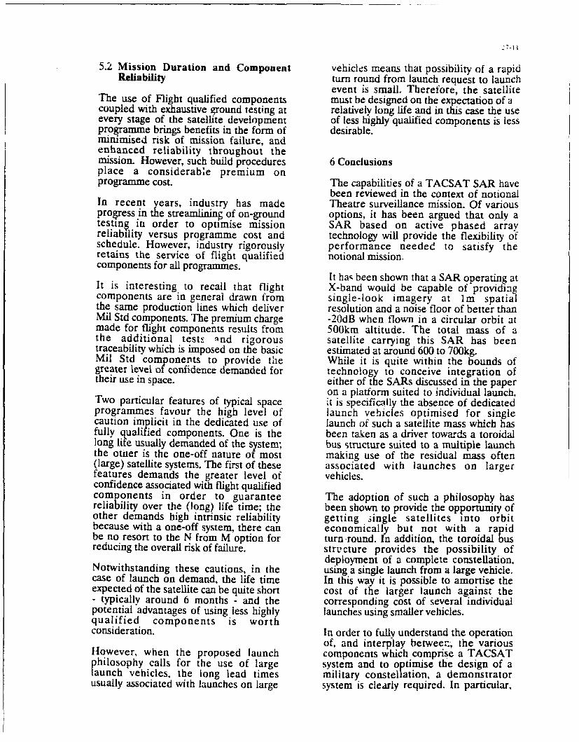
27-li
5.2 Mission Duration and Component vehicles means that possibility of a rapidReliability turn round from launch request to launch
event is small. Therefore, the satelliteThe use of Flight qualified components must be designed on the expectation of acoupled with exhaustive ground testing at relatively long life and in this case the useevery stage of the satellite development of less highly qualified components is lessprogramme brings benefits in the form of desirable.minimised risk of mission failure, andenhanced reliability throughout themission. However, such build procedures 6 Conclusionsplace a considerable premium onprogramme cost. The capabilities of a TACSAT SAR have
been reviewed in the context of notionalIn recent years, industry has made Theatre surveillance mission. Of variousprogress in the streamlining of on-ground options, it has been argued that only atestin, in order to optimise mission SAR based on active phased arrayreliability versus programme cost and technology will provide the flexibility ofschedule. However, industry rigorously performance needed to satisfy theretains the service of flight qualified notional mission.components for all programmes. It has been shown that a SAR operating atIt is interesting to recall that flight X-band would be capable of providingcomponents are in general drawn from single-look imagery at im spatialthe same production lines which deliver resolution and a noise floor of better thanMil Std components. The premium charge -20dB when flown in a circular orbit atmade for flight components results from 500km altitude. The total mass of athe additional testE ind rigorous satellite carrying this SAR has beentraceability which is imposed on the basic estimated at around 600 to 700kg.Mil Std componernts to provide the While it is quite within the bounds ofgreater level of confidence demanded for technology to conceive integration oftheir use in space. either of the SARs discussed in the paper
on a platform suited to individual launch,Two particular features of typical space it is specifically the absence of dedicatedprogrammes favour the high level of launch vehicles optimised for singlecaution implicit in the dedicated use of launch of such a satellite mass which hasfully qualified components. One is the been taken as a driver towards a toroidallong life usually demanded of the system; bus structure suited to a multiple launchthe otner is the one-off nature of most making use of the residual mass often(large) satellite systems. The first of these associated with launches on largerfeatures demands the greater level of vehicles.confidence associated with flight qualifiedcomponents in order to guarantee The adoption of such a philosophy hasreliability over the (long) life time; the been shown to provide the opportunity ofother demands high intrinsic reliability getting .ingle satellites into orbitbecause with a one-off system, there can economically but not with a rapidbe no resort to the N from M option for turn-round. In addition, the toroidal busreducing the overall risk of failure. structure provides the possibility of
deployment of a complete constellation.Notwithstanding these cautions, in the using a single launch from a large vehicle.case of launch on demand, the life time In this way it is possible to amortise theexpected of the satellite can be quite short cost of the larger launch against the- typically around 6 months - and the corresponding cost of several individualpotential advantages of using less highly launches using smaller vehicles.qualified components is worthconsideration. In order to fully understand the operation
of, and interplay between-, the variousHowever, when the proposed launch components which comprise a TACSATphilosophy calls for the use of large system and to optimise the design of alaunch vehicles, the long lead times military constellation, a demonstratorusually associated with launches on large system is clearly required. In particular,

27-1
the use of active phrased arrays in spacecould be demonstrrded and overall system .......performance evaluated. This paper has O f liP AMDWoDT (ashown that such a demonstrator is "is ,J.perfectly feasible using today's 30' 45- 60-technology.
10 26 32 45
3 87 110 150
1 260 320 450
7.0 STATEMENT OF RESPONSIBILTY 0.3 870 1100 1500
0.1 2600 3200 4500
Any views expressed are those of theauthor(s) and do not necessarily representthose of HM Government. Table 2a Spatial Resolution Vs Chirp
Bandwidth and Grazing An"le
BAWD MQMCY RA*NG &UAM D'TZ
WAXtX ( Gaz ) ( KKs)llAMA Giz ama
L 1.215 - 1.3 85
3 3.1 - 3.3 200
C 5.25 - 5.35 100
1 9.5 - 9.8 300
U 13.4 - 14.0 600
PARAiKtU VAU= I UNITS i COmM K& 1 35.5 - 35.6 100
operati.ng 9.6 (GCS) I-bandfreque•wy Table 2b Bandwidth Allocationsspatial 10 (a) Steeredresolution 1 (i) spotlight
20-50 (a) GMI C?!
mlaruiat Structure 1 SOdetoatable 10 (all Therm Control 20RIS Unified Prop By@l 50
minimu radial AOr.a (usinq TT) 60isdetectable 6.5 (knots) velocity Solar Array (1&') 15velocity V C412 otteroes (500obr) 40
Pfa 10-6 (-IB sl elro t 0
Pola ixation sub-total 360 kg
t -cDattirTMpreferred Donlink
Transmitter 15Antenna 5
Table 1 Desigun Goals for TACSAT SAR sub-total 20 kg
SIR Ba.kor
Active Antenna (6a') 200Central glectronice 75
gub-total 275 kq
Overall flatallita ass
Platform 360Oovnlink 20Wa Senaor 275
TOTAL 655 kg
Table 3 TACSAT SAR Dry Mass BudgeW

MWEMAM~2 P A3Co
A~TITl.4T
I y 1
Figure~~ 1 1ASA 7A 1ok~rto
42TA kam~ so -
4a~i R,) 71e -USAY3 AhMA A0A o~E~vno
AlmT ra )o0
c ToI
Fiur 1RC -ACA A ofrrto
/~~2 ,I
SATE46UT
IRA"
Figure 2 Q t~inMGeomtta Figure 4 Or-bit Altitude versus _Worst1Case&nstivly

27-14
M' P JI 1w vMUMs •m •'i
MA L M I? s"mum~i m" UA
Sr~mM~ I 'so - - -'
- - ------ K ,- -"-
-04" IT_
Figure 5 Sensilivity versus Distancefrom Nadir
ows ,,.,. w . we
S.... - : _____
mWM= Pm I"
Figure 6 Slant Ranit Resolution versusDirtance from Nadi

LO)W (OS'[ I.-SAi FOR NAU()O SI ' KiAA(
Charles S. 11offRemote Sensor c S%5 seoi I'rgcrati\ii Marnager
Iluvihes Aircraft (iirnpaiis
R0. lBs 929199
IBldg. 5SS, %IS X 32.4
L-os Arteries. CA 9(11)0'UfS. A
SUMNIARY aind hatile upport missions, lie vreafic'inci uwLeife sLle costCost and pe rfoirmnrrce iec htii nb breakIhiouehý ni rcceltil saser isreticliuc inc di dul launch Li111txear% have made possible the near termn develompmenit anddeplovnieni of' a lomw cost TACSAT surveillance ssse.the 2.1 ILAINCII COSTS AND ORBIT AiLIT] -DE
potential for both the spacccralt and sensor to he launched on *ssae.ieiili air i il~ els uttcia
lower cost launch ss sims is the fundamental basis for reduced sr elacisith'curn cotiheIn t5 lesstmcost. AdditionallN. the spacecralt and sensor iunsi he Iiee.i' uti lrcI eedn niepslmdwih
amenable to lost cost mnass production. For all wceither,.1nrd the characteristics of the inrht,is into w&hich the pa~ loads,
day/night surveillance, an active ss nihetic aperture rzi,!i imiust Ns pl aced Fori radar. fo r e5aitpie. t% tilhe sen or is placed
(SARi is the ideal instrument. and the ahi IiN it) m;!055nt livi) ighr and h~'- orbits. the sue it tile radair iolten
mnanufaicture thoiusands of very low, cost tr'tnt/eci ) rc , elrred to as the poster awerture priidu ti inicrease!s lie .tiruie
miodules has been deseloped Lii lighes. Since thle size ofi ai .' the rantie ii thle imirril postekr I Inus. at the hwiher orbital
SAR increases as the orhilal altitude is increased, a ltrial [ lttue antisLie ior vesei apasskise cnsor ksill he much
element of the cconnrriial basis for a loss cost l*ACSXT is tile greater in si/c and ss enei,11. Sonc spaLCcrIttf pa\10,1imad'lanch
definition of i ow earth orbit (LEO) s pace ciinste lit ionN ý iii tiqts s ar\ fi re tk it) iie aind %teciiit amfLid is th ierefo re itt cch
high Lmisiim utility. Tradeoff's tire J.ko provided iti comipare orelr ecCituiiiticJi Wi iJiikIh igittelr pAo I(ads itiii LE O. thle
sparse or zero based peacetimec consellatiimii ssith siurcge r h'I CN12tlM111ln oh i~ ~ fx ei
launch capabilities it) small peacet ite earl,\ ssartuirt LEstouireiui itice t al %th; h
constellations that can also instantly provide regional comtbatit nme iL pcca /esr eurdiipo d hsupport on demand. riecessars Slessinc [title oir cos e race it the reeo tii no theater in
qluestion. It is a truistn (ibt(irs the orbit tiltude iti satellites is
1. INTRODUCTION reduc ed. i(lie ntutmtber it spavccratli rcqu red tnitia tint an the
With the decrease in the loine range ICBI Ntratec'c threat anid attic g~roiund es ic CFe.iVC increases I radeott ts hat can
the increasing likelihood thilt theatter or regionail engagemnentsý wittnprounirr tire Lonite t'etwecni orbit altitude aind spacecraft
are the niiire prohtible tormn of cotnflict. oral and battle aireai i:ttstllitiii wie are pircseriied liter
an ecill ance ascendsk ti pairamountt importince. 2.2 SENSOR TllEClINOI.O(Y AND COSTS
Such missions. as regional treatv mon turing arid] verificatiotn. I, ir cirrptitibrit "It ih tile sm1faller, inure econormictil launch
area observation to Idetect military, buildu .p and mos ernent, 5> stem) archtitecitire. tire sur. eil tince ctisior tiust he ultra-
tassessment of foreC strength. characterization oif depiit~merit ihwth.littnihe mtirtnterhir ehoo~li helements. and hattie damage assessment must be addressed. A sensir is thai it be itirreiribe 1i3 lows cost Ortiss producibihit%
Major tadded iiperational' requirement to aiccomnplish these S pecttrctilk. tire prouiictii/atiii ilesren Miult lenld riselt to
nmissions is that theý he perliormned unrder till sseattter .iitiutateil. niio prn .itni prouiictiion .ind iest
ciondittons and during the dtiv and nicght. Nutmerous ajdcs \ descriptmon 'i rite ss a' this hla% been a(complished tit Hughes
have shown that such- observittions tire' typically beyond the ior spacebome radars is presented later.
reach of' organic assets. includo- birth ground tand airbornre .4 FSSPAErssstem%. an -d therefore ssould best he satified by spaceborne CON .AU TILL )EAA)T10%l PA-EIM-sensor plattormos.
Fwo stivs oit ctirrvine out rec'ional iir theater surveillance are
2. ENABI.NG~ TECIINOLO(Y irbviitit [he first %Noiuld rei% on triirpace resources to
rhe cotnfluence oii tio sicnifiictint esens--.ntinely the es olutioi tiscertatin thiit elevaied threat levels tire L rnt merit ori have
tind irer'(gtit ii ni iii tie regional in issions dlescribed tmlote tund occurreil. Hire second ssi ui I rel o n tire peicet m-e Ql obti reach
the maturation ot the essential enabling technolocv--htis nmade "t sptace ttit)nonitor aini proside the etirliest piossible starmnin
po-sible the near term satisf -action oii these mission shortfalls. AN that ti thretierriminti ýiitiaftur is des-duping Aliso. ahbrtii
is suggestiet by tire scope irf this svmpost um. tire siolution lies tin tipprotichI thiaLt has nio or ai sinrgle strs edl a nce sptcecratit on
the develiopmnrtt tind deploymnent of LEO pTicecraft tand sensors orbit tind that primvries tor surc' e ittirictes (itt additional sensors
that ean bet prodruced aind ltaunched at low cirsi. Analysis his to supporir the execuirlirt ot thetiter battle is feasible.
,hown that tire majiir wtay to ecoirittitte oin space systems is t0o lite abuse slichotoniri Iris sen impiotiant imiplicattion, hr thedevelop tiltrtt-lngittwciuht paicecraft and sensiors lto facilitate their jeilesigi nd ioperartiontal clitrticteristics -4 the sparerratii anidlaunch ion inexpensive launch systems. Many low coNit hoosier suvilneirrirettIiieshspiredtttsssiiýssteins are already as tiiltible ito place lightweight sIpacecraft intoti latunch -ott deninittd spree %Nlsetn) thati woiuld be dtle oi ped wsi thLEO.; Pegasus. Ttturus,. Titan IL. Deiat 1I,'\tlas. D~elta, Artane. tile hillwins tg operatiional scentarior tit mindetc. Trhus, whenever a spaice system requires munltiple launches.such as to replace relattively shon lived spttcecraft/sensitrs by [tirc 3.1 I-A '( "M*-ON-I)I-I AND) OPERAU ION Al., SCENAARIOtirsrtion of new technoioigv. or to establish a small constellation lit stiit issti, c-rusing teen tomr dedicated tind Jas irable spaceiii pearetime satellites, that etin ttccornplmsh both early ssamtcninp uippnnrt (or itactical Fittlttit\i ritimtittilrrs. tire tiuture paice s~ stms

1 iihth repicxcrit I vIcil ii. diieparitire froim (lie %,i' eurtet trmi Nwtraicc III tile held. rapidicr L!1Ii- eO~h ekOLu Anld LIiiiwh Al
%pa te tms are deicricttd. built. .inid depliixd. I lic i.0%aiticd '!IO'\kII III 1-'lttIiT .i I~e [ iii~i 1k11 i.1uti 'Altettit ý)uid b"
s,)atcxhornt radkar \%itlid fx- deignetd for qum prixiucttion longii Omipatib'ic "Jllt 1tii\% .iV itt. Itf .1iti~ a J'12,1i'i t,1Iii 'li
ternt ~toitaee. and easN ciockint such a, th tile IAW O-iie-aiit aid x~ouli he dcieed iorli hItk oxt. qI.mitilil poitnioin~ it- Ili
mittNric kq'~emst' hLut1 fo rw eas kt ffu Iiiitie \ urpisi-ngl\ clo~e tadar mciclavt \rolztd be tal).ihle Of !L'11i 1 t fn iCd 1t1rAcet It 11
iiatth h0%enuei life content ol ei am c nlit-lii~i c. dci duped h.\ th1,1 1 Ikieu\-vkI utc (ii dIO rCIutiF ii iuui i .1'%,\ 6c ýJ.UIir IhC tdiliii Ii cN and xpacccralu \ ýaN ii'.i efedr. Npe' itrcalI\ tile 11J.1-ittiu left-tell~ -11117111teC "uni)lfk) .uvuut tfluid, Ofcru fit(th
ivi-centlt-ics IIit lei tiotal un iiit it enis (11 sili ture. uu la uaut. aniir i~utda[ iu tl hi [fie LIhC Of imi c utII 'ij~pof erquipmti in the
1RUINiupt lul \%icrL rettarkahl-v similiar. \fail% unt ihNcc rili-silc ue r k ic tunor\ anud the clici Iuit 1..Mll ul %"JI I'L 11-ii al Iee u'j J ICI Or
PEGASUS FAIRING
SOLAR ARRAY SAR SPACECRAFT - -
DATA LINK ANTENNA
a) COMPACT OPERATIONAL SPACECRAFT
b) OUANTITY PRODUCTION c) LONG TERM FIELD STORAGE d) RAPID ACTIVATIONICHECKOUTAND SIMPLE CHECKOUT AND LAUNCH
a) PEGASUS LAUNCH I) SBLV LAUNCH
FIGURE 1 SAR SYSTEM CONCEPT

28-3
FIGURE 2. R;EPRESENTATIVE OPERATIONAL SAR SYSTEM
3.2 PE V(ETIJNE SP'A( CE )N% I ELI. IO\ inalld .,iicniio itmn'iiiic' imimiand tor tic, ý4 \R ioi ~ofieh~lccSC ENA.%RIO ( por sI it i \i,-, im i( liarli It t:heIkre xIre iFc(IýIII~CLI etIiCo I'seL-O
Uocirrars\t (iihe laiunchi on-demiand 'sciiirw'. the piccilicic ;iaw i,,, liedc iii a it, ue vi ie I ý, tile S.\R.1iaicihiriie raidar sCCMMiarcui ikes tn'e 01 1 s111a01 1 IJ) mf., i 'iit Lli. i ( iiariie j it-loh tc'olktuin. uwine a 'teancint!oniciatljicon iliac proi ides broad iaea ciit-atc 'remch t. ý -I I cii eiiii .:, a... I ipww I tepAe11111ý IA I 10() N' IN Ilk,ff V-d iii""tr., W'e
Iiigh remsIiuaoun cimauicg uiponc the dICec..ti'i iir citemL it i iciiuiii \t nine 1-4. a ') \R plicii.e"c i 'iu~cl prii.cs'ic
target prcsence. I ins scciario dloes not pi..cliidc[it' lie ,10 ilO ,I I' ill cliked to fihe cIii ole -'riiind siaiioi. "filch~pab Itts cit excutcec a sicrge launch tl sit pplcmnent a peacet me e [CaCll .1 ,is 1,1Cr of cnm rnisa nik'.
..onstcllatiirc or to reconstitute the ss stem as macllitic are
les~trivwed dUring1 major coicti ci. I lie centril 0i till hi' nt IM i 4. ( ( S \', I) E;RFO RNIANC FECHN( IO\I .;Yis ould rcsidc in tie theater ciommander %ii Also 1a' tile ICR \K I 11R01 G(1rcsponsihiiict o ld capahihic% tor real cone Taskiiie ot thle [-or ses ral decade-, Ifuluhe ha'1 d'sdoped space basedspaccbiirfl radar and spacecratl. In Fiteure 2. thiree raidars imdars that lisc~ performed tis ii diitimictoci. One tit theperatiriv. in) til SAR moode arc depicicdi. ,inc protidiir e striill c-ArICt w iIoircccr \eriia tit I S. o hc i a the first
n~ap iniagnici In a is icl 'Irel targiet dcececiion mnode aInd fihe jmcv.cr~It (o 1111p1 \ C111.1 "i.11(s 101I tnorPiicii n'Aic 5. Nsciwl tMo pros dfing tiw hcigher resolution poitlwuhimve to ais is.cptiiitii resellin 'L ifiiiith r1mil~ct. dcspiite thc fact
il haraciceri/irw cuems tarcicts cthat hate bccn detected. Moide ihl~ [lie S~ -\R reiulutaicio \s as approxiinateI I\ 10f) k in.hianncz int'iuctions to loo in difrn rafreape r khvt . IUVIC ililicdI ThleMe Iiradar. si bc h
,onlcoandeic in real drne hi\ hc field cominanderý moiilek Iltappcit \ cmii]i at j conisiderahks hii-licc reso1liion
coitfril tition. siwhih can Almo a,.ccpt ornhiard priicc'e i tcc'AlIS pe shutitc'bs ona Iliahc
pairtialls price sied imanictit data fromt ihe iirhticnc ratdars. radar and c:iltjnictintatiorls sstcn. ix hi 1t,1' beer) Li'cd
0 epcnidiie, oin thc caine franmc ot the tiri lauinch. thcre i, titt su(CceShI[Ill and relicateikl tor spuce ho.. ktin and spajcccralt
impoirtaiit tradcoih hetseiice aLCOMIin)sIIII)g aLlncti retriesal ntiatciscrs. *\ look, It l11C NMi-CeLa 11111,ccratt
priwcicgl,- imibicari the spacccratc. ii.. udicigl eiiiipaiiiin o [Figure 1, hicimi iliac the SAR ftintioined tis h ainput dc.l, tW stolrcd to.,gICN of potcliicIl targes. c s[ticc ..citt cut oI0al Parabiilic antenna and iniplin cr ltube Aind that its
uliiwnlinkitcg oti rather Aisdehand irnaiacn da Ita for near real pertcrnitmitie is as Icinitcd to chice kinuts it posic/rIatplctier
lttnic processing, inl [lie coccmanalcrs -roaund control cowioic. prdcsaalacathe ict abilIi'r5sosihelatcr s ostltkl\ iihc rctrrct.untl eicipetc]\ t ii architcttcure aind performa~nce .111"tibi(Cc ciomparison
Thekiter ý m~t jkc.% (, e pefered unil ollrl ý beiseeci tfie \ivehlan architecture mtid ihc Ituichesuiltreliable iuiiuprotesmsinu ot imaigiti data hia, been suceeesItillu rdr tiils\t htIli cIIcirs ciiuc b%alildaccd. [the Implementatiiin ol an etficient is debatid radiirs ntiiiii Noite tiatic ticle reipflietr ucdccpusci a
diisso~ri nliitk ismte titre straiiliiiircir and] canpr~e ai hcobcrklomilink ~ ~ ~ ~ ~ ~ ~ ~ ~ sn Ic bl, tahtrar n a ~ntj, h n l ack Ibox~ transmi tier andi receiver A miacor
rudar irri ito p'os-ilev thle COinruni..aiiiit downlcink apertuire shrincg ciilti rhtcuc 'tepo ema i
othati aiuitfter irait'immtictrantcnna \woud not be ncicssaIr\. us i c cic he i of pI sc itrv ac ineIture iii thc poir ibeam 11 agtci cit
file luroius ws otti a ciutncimmidersN .. ictmimind conitrolI l~T1I the ccitcnic. fur anciv beamn sccer nit iir scanning ic, iode uti
Inid sciik \tjititi~ titask and otitrol Ice 'c'icecratt imid ~cnsor. oiperatioiic 11cc pliaseu arraN, architecture in the bottomi ohproiuNýcs .ollected data, aiii piriivide data tIsLin01 as reqluired jý Ire I iure soxi.s [he ahilitSý tii conscricc uInd depI0c c %ry
itt essenctal parc t Ilich tiital iperatiiinal s\ temi. aiiirle kith thei cc tre arra\' s isih thousands, oft imA powAer I R channels that
%is iehatidlreal rimeduouscilink ii-iicccrciii't~tiiscn piox I tc cssenttiall mnufcls pertoruTna~ne. V.'cen clii'architcctuare is iiscd iii a 5paci! connunciibionNtiil node. for
A\ itprcal iipcraitiional triucline hia' beciu ie~lcoiped iii exanimple it mciansý chat %er'. small. hiss picuser griiunddemoniistratc how tile ,-Ntem imcttOft operate As hiticsc in termintal, c:iii he ilcplo\yei to operate \xii (iithis spaceborineFiguorc us the 'naceecratt rise above the battle area at ltime apertuire f'ecause ot its poceccc alt. Is argle fiiircct asit and FIR P1-1 If cit ll beits t preprouiin liiied hriuad area tcrip itap scarch P'erhaccs the sitle telý cisctiripiri~an cicaracterisntc. liuusever. isfor enenim targets .\c cite 12. tice tmcbile eronid station wsiit a iliac (lite pitascd arrai. pr'. ides fur tustauttacicous beacci

28-4
SAR SPACECRAFT
ELECRIC SARA PA-YLOA
I ON BOAR CONTROL--AN PROCESSIN ORBIT
IC LComm DIRECTIONARRAY
• 'sWIDEBAND
DOWNLINKL - - - - - - - - - - - - - - - - - -
COMMANDS: "•IMAGE DOWNLINK
FT17)
LEGEND
Ti SAR SPACECRAFT COLLECTING BATTLE AREA STRIPMAP IMAGEST2 MOBILE TACTICAL CONTROL COMMANDS SAR TO SPOTLIGHT SECTOR CHARLIET3 SAR SPACECRAFT SPOTLIGHTS SECTOR CHARLIET4 SAR SPACECRAFT DOWNLINKS SPOT IMAGE TO MOBILE TACTICAL IMAGE
FIGURE 3. TIMELINE FOR 7 MINUTE SAR FLYOVER
,canning in all directions. Typical applications have provided components are deposited Ailhtin ribbons ol ceramic. and the
for off-horesight scanning in all directions of greater than entire package is heated at approximately NX)rC loter than the
60'. A principal physical attribute that is essential to the temperature ordinarily used on ceramics. so that the total package
NATO architecture of the future is that these large phased is formed at once without damage to the functional devices. When
arrays have a very low profile and estremely lightivetght this process was begun years ago, a single channel T/R typicall\
densities-approximately 7 kg/m2
or less. cost several thousand dollars; today these device% are available
Spacebome phased array radars for military applications have at less than S99) each. In addition to this. Huehes. under a US.
not existed tor one reason: cost. The mafor cost item has been Government Manufacturing Technoloiy MANTECHI
the T/R module, since a given radar application may require program. constructed an automated rohbottci acility that is
thousandsf or even tens of thousands of these devices. Hughes dedicated to the mas,, lo, cost production ol" I7/R modules for
has made enormous investments in T/R modules that were radar applications. This facility. which was newIv constructed
primarily directed at airborne applications, since Hughes has and dedicated early in 1991. is being further autormated each
been a major airborne military radar supplier for many years. year. and the cost of T/R modules by 1994 will be between $2(X)
These T/R modules incorporate monolithic microwave to ,4tX) each. This represents an order of magnitude reduction
integrated circuits IMMICs) that are mass produced. weigh in cost from a fess years ago. Refer to Figure h.
appmxtmately 2 grams (depending on the frequency band), and aretypically packaged in a I x 0.3 x 0. 11 inch unit. L.)w temperature 5. REPRESENTATIVE ORBIT CONSTE.LLA rI)ONS
cofired ceramics (1LTCCs) have been used for several A wide variety ot low cost. high pertformance space
applications. I.rCC is a technique in which active and passive coinstellations can lx- des i, d. One small constellatiisn would hI

28-5
FORWARD STAR
EQUIPMENT SCANNERMODULE
PROPULSiONMODIJI.E
ROCKET
HIGH-GAIN ENGINE
ANIIENNA '¶MODULE
rHERMALCONTROL
S OL AR PA NELOVRDRIVE AND"-ABLE WRAP
LOW-GAIN BUSSOLAR PANELANTENNA
ALTIMETERANTENNA
J LAUNCH PERIOD 4 27 89 TO 5 1T 89
_ CRUISE___ 06_TO__4.8__AYS____VENUS OREIT NSERTIONCRUISE406T0448 DAYS, 8690 TO8890
r0 TESTAND C(:,,BRAT O, F DAvS
RADARPMA:PIG OF •DM!SSONAV',
SSLJPEq!OR' n -P0 C©N,-,NCTION URECOVER'"
ENO PROJECT [
JAN JUL JAN JUL JAN IUL AN
89 90
FIGURE 4, MAGELLAN SPACECRAFT
MAGELLAN
. REFLECTCR
BLACK BOX SINGLE TRANSMITTER RECEIVER
* MODEST POWER AND SIZE FOR COARSE
RESOLUT-ON
P POOR BEAM AGILITY
* DEPLOYABLE LARGE ARRAY ANTENNA
PHASED ARRAY 'HUNDREDS ITO THOUSANDSi OFRADAR TRANSMIT"TERRECEIVERMOOULES
DISTRIBUTED OVER ARRAY
• LARGE P*A PRODUCT NEEDED FOR
MANY MISSIONS
" EXCELLENT BEAM AGILITY
FIGURE 5. RADAR ARCHITECTURE COMPARISON
placed at an orbital altitude of 600 n.mi. [see Fieure 7). If truly Another four-satellite constellation ,•ould he placed at halfglobal surveillance coverage is the goal. including excellent the altitude of the one iust described (see Figure 81. In this case.cIoverage over the pxoles (which is not the most likely scenario for the altitude tor all spacecraft would he 30)0 ntmi., andthe majoraty of the NATO theater surveillance mtssiontsi. a the inclinations tor the spacecraflt would bN ('. 9(V, 57', andsystem ol four satellites comprising two planes with two 57', respectisels . The orbit period for each would hesatellites each, all with a 9Xr inclination, would be feasible. The 96 minutes. and the average rev,-51t gap globally %kould rangesatellites would be separated by 180' within each plane. The from 2 to 4 hours. Figure 8 shows the ground traces over threeglobal coverage would be very good in that the worst case revisit revolutions (4.8 hoursi for these tour satellites.gap in the entire world (meaning the time during which no sensi)rcan "view" that particular area on the earth) would be 1.54 hours 6ESG NW(and this would be a rare occurrence). However. the averagerevisit gap for every place on the planet would be 0.62 hour Hughes has developed a low cost spacecraft and SAR payloadIapprostmaiely 37 minutesl. that represents one f(orm t flow orbit. long life approach to the

28-6
CURRENT MODULE
FEASIBILITY MODULE
PROTOTYPE AND PILOTMODULE APPLICATION1,- 19600 SPECIFIC
PARTS-45 A SINGLE CHANNEL
INTERCONNECTS- 1 9000
320 PER CHANNEL PARTS-22INTERCONNECTS-"164PER CHANNEL/ / PARTS-13
// •NTERCONNECTS 157 PARTS- ItPER CHANNEL iNTERCONNECTS
4000 [ / I , 90 PER CHANNEL
Z 3000 V
o 2000 -
LO0
10001 _ "_
TiR 1989 i 990 1991 '992 '993 1994
MANTECHI 0 I0
PROGRAM 30 NEW FACTORY 100 000 250.00
MILESTONES CHANNELS DEDICATED CHANNELS CHANNELS CHANNELS
NOTE MANTECH MODULE EVOLUTION PROVIDES COST AND PRODUCIBILITY BENEFITS
FIGURE 6. MANTECH PROGRAM
problem. The goal was (a design a lightweight, lo'k cost,. 4 SATELLITESmanufacturable spacecraft that could support a fair>. 2 ORBIT PLANES AT 90 I
substantial (but ultra-lightweight) SAR and be compatible with 600 nmi ALTITUDE
the Delta 1I launch system. The design is for an aftemoon sunsynchronous orbit "with an altitude of approximately 370 n.mi.The primary solar power system is approximately 5 kW. andthe SAR array is approximately 12 x 4 meters. for a total areaof 48 m2. In this particular design. it is desirable to include alarge (6 foot diameter), dual gimbal pointing parabolic antennato relay wideband SAR data to a geosynchronouscommunications relay satellite. Furthermore, an X-banddownlink is provided to enable real time SAR data to be .
transmitted to operational users directly below thespacecraft/SAR at any time. The entire spacecraft, powersystem, radar, propulsion system, and all onboard electronics NATO NATION COVERAGEare designed for an orbital lifetime of 8 years. AVERAGE REVISIT TIME 0 D 62 hr
The very lightweight spacecraft for this application is a WORST CASE REVISIT TIME = 1 54 hr
simple triangular truss arrangement. whereby the SAR array FIGURE 7. HIGH ORBITAL ALTITUDEis affixed to one of three sides of the bus, and each of the CONSTELLATIONsolar wings is attached to one of the two remaining sides. as isshown in Figure 9. Note that in this figure. the fairing above only. In this particular design. the requirements are for ±30'the Delta If second stage has a 110 inch envelope for the scan capability in the elevation axis and 20' scan capability inpayload, and the large reflector antenna is also accommodated the azimuth axis. Similar designs have called for the array towithin the fairing. be deployed normal to the earth's radius vector to more readily
Figure t0 depicts this spacecraft/SAR payload in the space- scan to the right and left as the spacecraft progresses along the
deployed configuration. The SAR antenna is canted orbital path. In the latter case, the designs have typically calledapproximately 30' off the horizontal. to permit side-looking for ±60' of scan in both axes.

4 SATELLITE CONSTELLATION
AVERAGE REVISIT GAP WORLDWIDE 274 hr
300 n mi CIRCULARI -0. 90. 57. 57 PED 96min 3 REVOLUTION GROUND TRACES, 4
FIGUREO 8 SATELLITES GRUN TRACE
N0 11-0 N04
TNVELOPE
'OtDIAMETERPARNY -
,2-STAGE CONFIGURATION)
3 POINT INTERFACE
SPACECRAFT TO
LAUNCH VEHICLE
FIGURE 9. SPACECRAFT LAUNCH CONFIGURATION
VELOCITYDIRECTION -DATA LINK ANTENNA
, (DUAL GIMBAL POINTINGi
SPACECRAFT BUS
NADIR I IDEPLOYED SOLAR ARRAYS
I i0 PANELS497 ft
2146 m2iTOTAL
SUNLIGHT
TRUSS-SAR HR
STRUCTURE
DEPLOYED SAR ANTENNA6 PANELS 49 Mi
2 TOTAL
FIGURE 10. SPACECRAFT DEPLOYED CONFIGURATION
28-8
Discussion
Question: May you give (rough order of magnitude)how many PEGASUS launched small satellites you planto build to have an economically efficient approachin terms of manufacturing facilities and effectiveservice?
Reply: That one concept was based on a Customer long-term need for hundreds of spacecraft at very low costto be deployed in the field for long periods. ThePEGASUS solution was a design constraint, but is highin $s /lb to orbit. Multiple spacecraft launchersfor peacetime constellations and short (approximately1 year) orbit life may make more sense. However, thevery large, high performance radar (on Delta II) isclose in cost to the TACSAT goals discussed by CharlieHeimach, et al.

31-1
Cost Effective TacSats for Military Support
By M.T. Brodsky, M.D. Benz & J.T. Neer
Lockheed Missiles & Space Company, Inc.Organization 6F-01, Building 590
1111 Lockheed WaySunnyvale, California 94089-3504 U.S.A.
Abstract devices and GPS receivers, an IRIDIUM subscriber unitcould be ideal for several voice and precision location
This paper discusses the key space system features functions in peacetime and limited warfare situations.required to provide effective support to military field Another military benefit from the IRIDIUM system
units and discusses Lockheed's concept to fill critical may be the user satisfaction model it provides. A likeniches in military surveillance and remote sensing. philosophy, applied to the development of military
surveillance systems, could produce huge benefits.The military is aware of benefits available from moreeffective use of space. To provide those benefits, space Any discussion of a new military capability mustsystems must be dependab!e, easy to use, flexible, address new world realities. The welcome reduction in
responsive and affordable. Ihis paper describes how a superpower tensions has come with unpleasant side-programmable, multi-spectral E-O sensor combined effects including greater political instability, local "hotwith a new small satellite bus, and supporting command spots," and the danger of a local conflict spiraling out ofand control and data processing tools can provide control. The political reality of reduced western
environmental and surveillance support to users in military spending and constrained forward basing
peacetime, crisis and combat. Also discussed are how accompanies these threats. The factors combine to
such a system meets essential military utility criteria demand greater flexibility and responsiveness of the
and an approach for rapid TacSat system development, remaining forces. The Persian Gulf showed that timelyevaluation and deployment, warning and intelligence information in the hands of
commanders can produce force multipliers that allow
Introduction the prosecution of conflict with low casualty levels.
One consequence of this environment is an emergingIn an era when businesses are learning the importance need for user controlled, cost effective, tactical spaceof total customer satisfaction, developers of new space systems to provide timely information to commanders.systems have opportunities to achieve similar goals. The systems could give indications and warnings ofJust as products emphasizing user convenience, hassle- force build-ups, allow treaty compliance monitoring,free service and high quality at an affordable price are and support national and allied forces in peacetime,essential in today's economy, space system developers crisis and combat. They could operate in modes tomust use emerging technologies to meet similar needs satisfy the different needs of several users.for civil and military systems. In the commercial arena,a system designed for total customer satisfaction, The needed capability can be effectively provided by aMotorola's IRIDIUMTM/sM global personal small LEO satellite with a programmable. multi-communications system is in development. The same spectral sensor combined into a "TacSat" space systemphilosophies can be reflected in a tactical surveillance shown in Figure i. Key TacSat system features wouldsystem and the projected commercial infrastructure can include a distributed architecture with direct useraid the economic feasibility of such a system. tasking and data readout. Technologies central to this
TacSat system concept are multi-band. CCD focal-The IRIDIUM system provides global personal plane arrays, satellite on-board computing andcommunications using a constellation of small LEO advanced work station ground data processing.satellites, supporting ground facilities and a userequipment family including a small, hand-held Mission Requirements & Tradestelephone and a variety of data terminals. The systemthrust is to provide cellular telephone-like convenienceand quality with 24 hour dependability anywhere on theface of the Earth. The IRIDIUM system will provide At the most basic level, the fundamental requirement ofhigh quality telephone connections anywhere with the any system is that it satisfy user needs. In a militarysame effort normally required to call between offices in surveillance system, that translates into a need toa large city. In short, the IRIDIUM system applies provide timely information on force disposition, localstate-of-the-art technologies to make things simple and environmental, infrastructure and other conditions to
convenient for customers. With modern cryptographic commanders. It is technically feasible to build a space
IRIDIUM is a Trademark and Service Mark of Motorola Inc.

APPROAQLEUSER PROGRAMMABLE SENSOR
UNSATISFIED NEEDS" INFORMATION FOR
THE MILITARYCOMMANDER: LOW COST, HIGH PERFORMANCE BUS
- WARNING
- SURVEILLANCE
- ENVIRONMENTALSENSING
"* FLEXIBLE, TIMELY,RESPONSIVE AND DISTRIBUTED C3 ARCHITECTUREON-GOING SUPPORT
"* MILITARY TASKINGAUTHORITY
Figure 1. Military Needs are the TacSat Driver
system with the spatial and spectral resolution to do the that meets these varied user needs at selected times.job. It is harder to retain adequate resolution while Using low cost systems and technologicC, it is possiblesatisfying frequent coverage, large area surveillance, to achieve high user satisfaction with a robust andtimely access to information proaucts, case of use, and responsive system a,,.hitecture. De-centralization doesdependability needs, all with low system costs. Many not result in higher costs than current capabilities. Thisthink that the simultaneous satisfaction of these needs is architecture, shown in Figure 2. manages resources tonot practical. It is practical, however, to build a system fit a situation and is the thrust of our TacSat concept.
Hous S ceHelt
Production Co
Figure 2. Possible TacSat ArchitectCre

Design Features This is possible through the use of two diffeient focalplanes and the flexibility to operate in either -staring"
/ , or scanning" modes. The "staring" mode captures. .,high resolution data of a relatively small geographic
. .- ' ,area. In this mode, a sensor continuously tracks, orOperational "- "tares" at a particular target, and the image size is
Characteristics - - limited to the sensor's field of view IFOV).vI42Irg CipoblIty X
IN;ghl Utility X X The sensor can scan in either the "push-broom" orWOW. op,& "whisk-broom" modes. When scanning in the "push-
Lg. A.- x X broom" mode, a sensor images a strip determined by itsTf,",•Ao,.st.IIfo x X x X FOV. A wider area, with reduced dim targetEK,..fus. X K performance, can be imaged using the "whisk-broom"
o...4.ty -X - x x - scan mode. This dual-mode capability, discussed later.
provides a surveillance option "menu" to the userFigure 3. User Driven Design Featuie Matrix ranging frcm small area, higher resolution to large area.
medium resolution. In addition, the pointing capabilityFigure 3 shows the key user needs satisfied by an required for scanning and staring also allows targetelectro-optical TacSat system, and how those needs area selection within a field of regard (FOR) of aboutmap into desired design features. The first system ±45' to each side of nadir along the flight path.design step is the definition of key mission drivensensor characteristics. These characteristics, combined In addition to user-programmable pointing, the sensorwith orbit selection, define the system's "capability to should feature multi-spectral capability. The scansurvey and collect". nodes might be supported by ;1 series of multi-element
linear focal-plane arrays, each covered by narrow bandSystem Performance optical filters. The high resolution staring mode couldTacSat system performance is fundamentally defined use a square panchromatic array operaung in the visibleby the combination of sen.;:•r characteristics and band. This combination makes it possible to supportmission orbit. As shown in Figure 4. the process of the many spectral bands and differing resolutionsselecting these parameters starts with the definition of needed to perform TacSat missions.mission requirements; i.e., what specific roles will thesystem be designed to satisfy and what performance Coveraielevels will be required for these roles. For example, TacSat system flexibility and timelincss are. to a largeone role might be daylight surveillance of a battle area extent, orbit dependent. Of course, orbit selectionto detect armor, another might be surveillance of a port often involves trades against resolution. Orbit selectionarea to detect shipping activity. Each of these requires consideration of options for altitude,missions requires some specific quantifiable threshold inrlination and, in some cases. eccentricity. Figure 5performance and a range of characteristic goals that shows some of the factors effecting altitude selection.affect tasking. The key to sensor and orbit design isbalancing as many tasking thresholds as practical while ENWRONEIr:maintaining performance against the variable goals, allat an affordable cost. "r...'y "CF
/ RSO M.-_o~r. /~l ,-ýbo.a-C9REQUIREMENTS 6'M.,rumAlft.d*s 4,14 KM TRL.W0
PFRFOPWMANCE & SENSNG OPERABIUTY &TECHNICAL TRADES USE TRADES
REFRESH RATrE EVLAEATENTV OWNLINK
Figure 5. Altitude Trades
Environmental factors bound the range of availableUSER.oTAKIG ARANSA C ,flLM oU P,, options. Below about 450 KM, atmospheric drag starts
'OWST, H P.RM4oRLACE.SATE S to become a factor by increasing propellant for orbit•LOW COST., pEH •Rr ORMAUVSAE iu •T.UE a b fo
,," RNA CO,,STELLAT.,ON,• STORE ON ORmaintenance and beginning to produce attitude controlAUN.H.ONoDEMAND' design issues. At the other extreme, altitudes above
Figure 4. E-O Sensor System Approach about 1400 KM result in increased requirements for
component h...r',ning against the radiationThe multiple areas of performance required for TacSat environment. (Orbits above the radiation belts wouldmissions are achievable in several ways. The not need as much hardening, but would require sensorsconventional approach is to use two main sensor types, of a different class than those discussed here.)one emphasizing wide field-of-view, the other highresolution. The key to our concept is the capability tosatisfy the key TacSat missions with a single sensor.

"11-4
Specific altitude selection between 450 and 1400 KM with the facilities and expertise to manage and controlinvolves minimizing the total system cost for a desired a single TacSat or a muluple-satelthte constellation.resolution level. As altitude increases, sensor focallength must also increase to maintain constant The operational principle is based on the idea ofresolution on the ground. Increasing the focal length field commanders using a predetermined scheduleusually increases both the sensor and satellite weight. of resource availability to initiate targeting. TheyThi,: combination of increased weight and altitude would know in advance of satellite orbital passes overincreases satellite cost and, generally, launch costs. their areas of interest. The rear echelon activity wouldHowever, the higher altitudes have several significant operate the spacecraft and perform housekeepingadvantages, First, even at constant resolution levels, it functions. Users would know that, between specifiedis possible to gain a wider access area on a single pass times, they could point the sensor, select spectral bandsby taking advantage of greater off-nadir performance. to acquire needed data and direct it to the appropriateSecond, if reduced resolution is allowed, higher user ground station. They would not have to controlaltitudes allow larger imaging swaths on a single pass satellite attItude or provide pointing angles. Instead.even with a constant down-link data rate. Therefore, a they would provide target coordinates. SystLm designsensible design strategy is to optimize for the highest features and user task planning tools would ensure thatpractical orbit (below 1400 KM) available with the the user commands were within system capabilities,selected launch vehicle. Sizing the sensor io provide and not potentially damaging to the satellitc.the required resolution would then give the bestbalance between resolution, single satellite coverage The strategy allows regional commands to use aand cost. This paper assumes that booster constraints satellite as an organic asset when it is overhead, evenwould result in a system at the low end of the range though LEO satellites are inherently inorganic global(450 KM), but no final decision is implied. assets. Users xould control the assets based on local
priorities. It would be possible fora command to makeOther important parameters are whole earth versus a decision on the best tasking use just prior to a pass.mid-latitude coverage, revisit times and the number of Nend command:; to the TacSat. have it image the target,satellites required to achieve them. Orbit inclination is and return the data for processing and analysis. Thisselected based on the desired range of target area high degree of user autonomy requires that the satellitelatitud&'s and the practical constraints of available and support system be designed from the start tolaunch sites, though some mobile launch systems could separate housekeeping and payload operations. Thiseliminate those constraints given sufficient payload feature requires a rear echelon support capability thatcapability. The trade is usually between a polar orbit operates the satellites and provides user support.and an inclined orbit, either circular or elliptical. The Satellite operations include such traditional functionspolar orbits have the advantage of covering the entire as: launch control, injection, check-out, navigation.earth with potentially repeating ground tracks. Their orbit adjusts and maintenance. User support includesdisadvantage is that the satellite spends a significant the distribution and prioriutzation of tasking allocauons,portion of its orbit over the polar regions. Inclined and the resolution of operational problems.orbits can cover the temperate zones or higher latitudesas required. However, it is difficult if not impossible to Figure 6 shows a typical TacSat pass. With the 35design an inclined orbit where a target is available at FOV multi-purpose sensor, a single pass swath width isthe same time each day with only a few satellites, limited by the allowable sensor obliquity. At 450, the
swath is about 1040 KM by 1930 KM at 100 elevationPet satellite coverage is a key measure of cost angle, The user access area is limited by line-of-sighteffectiveness and is, in turn, driven heavily by launcher from the satellite to the mobile exploitation sites thatoptions in two ways. First, use of maximum launcher receive the data. Reaches of 780 KM are conservativeperformance increases orbital altitude and coverage, and could be increased by reducing allowed clevationSecond, launcher flexibility allows varying, situation angles or swath lengths. The linkup is made betweenspecific orbits when appropriate. Another approach is 3' and 50 elevation and commands and other data up-a general purpose sun-synchronous, circular, near polar linked between 50 and 100 elevation.orbit that provides a global, long term capability.
TacSat operational objectives to maximize userSystem Useability and Operations benefits and flexihilitv and minimize userAn effective command and control architecture is the performed satellite operations drive the C 3
key to TacSat system useability, as shown in Figure 2. architecture. Distributed payload tasking is a key toThe primary architectural strategy divides control into the TacSat concept. Users require a system that simplytwo functions, mission support and satellite support. and responsively supplies support without beingThe clear separation of these two functions is hampered by insufficient satellite knowledge or thecritical to user satisfaction since it allows combat burden of additional infrastructure. Figure 7 shows thecommands to obtain satellite surveillance benefits C 3 capabilities divided into categories. Payloadwithout the burden of satellite management. This tasking consists of simple, user commands on a pre-support function, completely transparent to the field allocated, time share basis. Allowing users to task thecommands, is accomplished by rear echelon activities sensor payload in ground coordinates, eliminates the
need for user ephemerides and pointing understanding.

*~ ~ ~ ~ ~ ~ ~ ~ ~ ~ ~ ~~~~~~14 KM4t o, iittLrcc~ct L~c ~''rll i
I ~ ~ ~ ~ ~ ~ ~ ;L HTc ~r~i01 ~oo.Ii ~. rljI1 1 lillSATELLITE [ ld~ip AaTsa 45
ELEVATION ANGLEg- TIO.I(Co,,,and U~. ~~ I u't i I.llir. .1 '~ 2~ 1930 KM2Ii.~
1 ~~od 0, Osý,,t73o SEC)tT 1'litOs~~r ~1 11 'k 0.i l I I LI .,¶~.iI 111
5i otU~ru~n&f,,
3 rc'v SnOr KM 111II'IiI 0~l
"eII~frI r~ld, SATE Ih\,'
_________________________ ill ' ii ~ .RACK1~I ~ *i'I I fi~
M.g c>I S 5o, i,.tr Sat6 1 44 .. SfjII 1,10% 1c,:.,,s "t il
lo54.44 IP0*154l 4flAAI1S l 11 C I 1'U c
445W54AT0ea l *fl54S 544 .ih kl-. ¼ . o, I
PslldO f U $*~ut D"'!.I54 To '4... ,*lfl , -u IiIn I Bl- 00', - & *N -
Scno I ie ndDs

31-6
-APERTURE 045 M
• FOCAL LENGTH
STARING ARRAY 6.78 M
STRIP ARRAY 3.15 M
* OPTICS FIELD OF VIEW
STARING ARRAY .420 X .420
STRIP ARRAY 3.00 X .1°
• POINTING CAPABILITY ± 450
* 2-AXIS GIMBALLING WITH MOMENTUMCOMPENSATION
- SPLIT-STERLING CYCLE FPA REFRIGERATOR
Figure 9. TacSat Multi-Purpose MSI Sensor Concept
Multi-Spectral Band Selection array are located with the central I' of the line FOVThe earth's atmosphere has many highly absorbing where geometric aberrations are small. This has themolecular species. Their influences establish spectral disadvantage of reducing available visual coveragewindows for satcllite sensors to detect surface or near- rates, but is necessary to balance distortion andsurface phenomena. Waveband options must be chosen resolution. Using two focal planes with different focalconsidering target phenomenology and these windows, ratios maximizes the combined FOV and resolution.
RANG WAVELENGTH ,*,.PSE Physical law dictates that resolution is proportional to. ... the ratio of aperture diameter and spectral wavelength.
- 00*,4r f~ rFor apertures feasible on a small ,atellite, high2. ...... _•",, C ,GLU . ... Of,,o, resolution is attainable only in the visual and near-to-
am.,., 0G03GRAPHC GREEN (EoPWAý00D(*, mid-IR bands, from lower orbits. The 45 cm aperture4........ ........ Mt, u compromise provides good performance (SNR and
**. ..... ' ,,. . resolution) for most missions, and construction with
a . . am ,= ,..,, .... .. reasonable size and weight. For mapping. SNRaaa_ .. generally decreases and resolution increases with f/#.
I ,o. 10. -EATHE CLOW____ Ro., N The f/7 scanning-mode optical path is .i compromise"00 1100 WA TwE A f1VAMR00.RECr.0N." ,between SNR and resolution perfornance. In
Figure 11. MSI Sensor Bands & Uses staring, high resolution-mode, a higher f/# is desired.With a large square silicon CCD detector, an f/15
Multi-spectral information is highly useful for many system meets resolution requirements with goodTacSat missions. When used to supplement FOV and SNR performance.panchromatic data, the non-visible bands adddetectability. Camouflage can be detected as can warm For given aperture and resolution, wide-field-of-viewobjects against a cooler background. Multiple band sensors tend to be large. The design has a slightly offmeasurements can be used to compensate data for axis optical path providing a wide, one dimension FOV,environmental conditions such as water vapor effects. with resolution only partially degraded by geometricThe bands listed in Figure 11 represent an initial aberrations. This approach is acceptable for IR bands,selection based on expected targets and backgrounds of where diffraction blur exceeds the geometric blur. Angreatest interest and likelihood. The system and additional square high-resolution focal plane uses thesensor's programmable features allow specific uses of on-axis optical path and operates only in the visualband combinations for each mission with data formatted band, providing maximum resolution for designatedfor transmittal to the ground. areas of interest. Operating the highest resolution
missions solely in the shorter wavelength visual bandOptical Design Selection keeps the aperture size small. When sunlit, mostAll-reflecting optics designs are superior for ground and weather features of interest show visual-simultaneous use of different spectral bands. band contrast adequate for detection.Reflecting optical systems also offer feasible weights inthis aperture range. Except for small refractive The square visible staring array receives the on-axiselements providing image correction in the high- narrow-FOV beam through a central hole in the primaryresolution visual band, the design uses all reflecting mirror. The multi-spectral optical path lies just to the
optics. Detectors for the high resolution panchromatic side of the staring systems lens elements. Figure 12

1 2 Visible-3
- . - ThermalSisolator
*6 IR.8
*Visible Detectors2 Rows of l8umn square detectors, double offset rows. -9000 long1 Row of l8umn square detectors, double off set row, STOI
*IR Detectors2 Rows of 50um square detectors, double offset rows, -3000 long3 Row of lO0um square detectors, double offset row. -1500 long
*Each row covered by appropriate filters
Fwigure 12. Mului-Spectral Focal Plane
shows [tic multi-spectral Focal Plane Array FlP\j (ora% ýP!i~ X a Rawc,"§ o~p nddhK'layout. A thermal i.solator divides the FPA into *in Thiis helps to choose the scan rate, once the expeetedtincooleil visual and cooled 80 'K I R waea %:irvet and bac kLround ,w'nattures, and~or search areassecuons. Filters to define the detected waveband co,\ r are dICl rued, A comimandable ,srnsor allows operationsthe detectors in each pair of staggered-alinnn rO\-. ailored ito immcidiatc mlissionl reqjuiremntns.\kith m ulti -color data received automaticallv as the ro,.kssweep across the scene- Thc FPA lengath will likel\ Sensor operations could involve hi -directional whisk-require use and alignment of separate smaller line array broomn scans covering about a 14-w -kide swvath parallelsections combined to form the FPA. Signal-to-noi~e to the f'light path at up to -45- fromn nadir. [Destredratio analysis of a scene to be imraged or mlapped (nsu, ground resolutions are chatllengmoi to achieve Over theaccount for the observer's desired contrast level. !irll FOX' ýsithi a moderate aperture, especially in the IRBackground noise rather than internial sensor noise bantds, andi a wide field-of-view with reasonable andlimits TacSat mapping observations. This is becýause %keirht is needed fior these missions. Data dowAnlinkthe earth is brivht in most wavebands. especially tle rites are high for mapping' and surveillance missions.sunlit half. The result is the parabolic relation of Thlis makes it difficult to process and return data withincontrast to photon count. Since detectable contrist time constramins. These reflect the combinau-on of widedepends on photon count, for background-lInmted c:overage ant imediumr resolution. If attention is limiteddetection the relation between contrast level. required to a few areas, slower %;can anti data rates are possible.SNR. scan rate, and spectral bandwvidth, is: Figure 13 shows the wensor block diakcrain.
F PAyLOAD -ý _ _-RA;7T
Figuire 13. TacSat Multi-Spectral Sensor Block [Diagram

Sensor Thermal DesginWith cooled IR band FPA detectors, adequate sensor The ISE is the "heart" of the TacSat spacecraft. It is aheat rejection is essential. Operation of infrared sensors single electronics package with a modular data bus. Arequires cooling of detectors and other local thermal series of mission and application specific cards attach tophoton noise sources (optics and structures). Detectors, the data bus. These cards connect the bus systems, andif HgCdTe, operate with sufficiently low dark current payload if desired, to the data bus. A high speed CPUwhen at 80'K. To achieve such temperatures without is also on the data bus, as shown in Figure 16. Locallylarge radiators, mechanical coolers are needed. Two generated data and ground commands move to thesmall radiators are used, one for the mechanical cooler processor. Once in memory, this data is used toand on-gimbal electronics, and the other to keep the generate spacecraft or transmission commands.optics and structures cool. A lightweight, rapid-readiness, cooler with long storage life could be STANDR INTERNAL DATA BUAS
required for TacSat missions. In the desired size range,a mechanical Sterling cycle cooler is a good choice. Itoperates at a coefficient of operating power ofapproximately 100 Watts consumed per Watt ofcryocooling dissipation.
Since the sensor is designed to operate in the "push ,-- c.u, ,broom" or "whisk broom" mode, it is unlikely that aradiator would be continuously shaded. Somealternatives are: periodically moving the primaryspacecraft nadir-pointing axis off nadir, fitting a sunshield, or using a sun-synchronous orbit and "whisk P
broom" mode exclusively. It might also be possible to i e T Rchange operational modes so that radiator sun exposure Figure 16. ISE Block Diagramis less than 35 minutes per orbit. However, thecombination of a sun shield and alternating modes Electrical Power Subsystemcould allow shaded operations with minimal mode use The electrical power system (EPS) design should beinterference and allowing inclination choice freedom. simple and flexible. The system uses either gallium-
Satellite Desi*n arsenide-on-germanium or silicon solar cells and nickel-hydrogen batteries. Gallium-arsenide solar panels,while more expensive, offer improved packaging, lower
Figure 14 shows a possible TacSat configuration. The weight and reduce orbital disturbance torques andTacSat bus houses all equipment to support the sensor moments of inertia compared to silicon cell panels. Apayload and communications equipment. The key to single pressure vessel (SPV) nickel-hydrogen batteryTacSat flexibility and utility is a bus that uses a single can lower both weight and cost compared to anIntegrated Spacecraft Electronics (ISE). Figure 15, the equivalent individual pressure vessel (IPV) system.spacecraft block diagram, shows major vehicle These factors combine to reduce propellant mass.components and interfaces and how the ISE controlsand coordinates functions. The ISE processes attitude Attitude Control and Propulsionsensor data and controls orbit and attitude through the Three-axis stabilized TacSat attitude control andreaction wheels and the propulsion system. The ISE propulsion subsystem functions provide a stable sensoralso collects and formats spacecraft housekeeping data platform and include: determination of attitude andfor storage and/or transmission.
MISSION/PA YLOAD:- IR MAPPING- TOPOGRAPHIC SENSING MULTI-PURPOSE
• OCEANOGRAPHIC SENSING SENSOR
• PANCHROMATIC IMAGING
FLIGHT
C 3:- UP LINK - THEATER CONTROL OF SENSOR
SCAN MODES & AREA
NADIR - DOWN LINK - DIRECT TO USER FOR IMAGERY
Figure 14. Possible TacSat Spacecraft Concept

- __EPS •
01 ACDS 00v0 SPROPULSION L RL -
S ASENSORS BATTERIES 4
of CCONTROLJMOULA
l INTEGRATED
- SPACECRAFT --• AT ELECTRONICS PAYLOAD •-o * MULTI-PURPOSE SENSOR •
•P DSL4DLR RTS d
COMMANDS TLM CDATA•oPEE -2..-A CON-R-LTERRMATL. "
0 STRUCTURE & 4p DATALECTONICPAYODMECHANISMS
Figure 15. Typical TacSat Block Diagram
position, attitude control ,and pointing agility, orbit control sensor pointing accuracy. The Gr/E structureadjust control and actuation, payload torque and saves 4.9 kilograms over Al/Li and 7.9 kilograms overmomentum compensation. safemode control and de- Al. The primary structure provides continuity, strengthorbit, if required. The subsystem hardware consists of and rigidity between the payload and the interface ring.sensors, actuators and propellant storage and deliverysystem. All control law, safemode and other software Space-Ground Link System (SGLS) and high data-ratereside in thc ISE. Three reaction wheels provide torque antennas stow against the vehicle and deploy on hinges.actuation, with agility requirements and residual Spring driven mechanisms deploy both antennas andpayload torques after momentum compensation driving the solar arrays. Each solar array gimbal is driven bytheir size and magnetic torquers for desaturation. Low small motors and reducers. Flex harness and slip ringscost star camera sensors provide the kind of knowledge carry electrical power and telemetry across the joints.needed, with a sun sensor for coarse pointing.
ThMr, mal..DntroIThe propulsion system consists of a conventional Temperature extremes allowed in other subsystemshydrazine mono-propellant tank with propellant drive the satellite thermal subsystem. Assuming themanagement system, lines, filter, valves, general case using a non-sun synchronous orbit.instrumentation and thrusters. System pressurization TacSats would not have 'hot" and "cold" sides, as thecould use either a blow-down or a re-pressurization thermal environment varies on the satellite sidessystem. The propulsion system is used to correct depending on inclination and time of year. A TacSat is'aunch vehicle injection errors, perform orbit trim subject to many eclipse cycles and must be designed tomaneuvers and de-boost if required. accommodate them. For example, components that
operate during the sunlit portion of the orbit would haveStructures and Mechanisms a significant thermal radiation area to relect bothMajor bus structure components are: the frame, internal and incident heat. Unfortunately, when thisequipment panels, propulsion module, and interface surface is in eclipse, heater power must now maintainring. The modular design allows subsystem mounting the item with the larger radiator sized for the full-sunwhile maintaining alignments during test, operation case. Aibedo and earthshine (planet IRtransportation, and storage. The modular approach also heating) also influence LEO vehicle environments.reduces part count and assembly spans. The interfacering provides the structural load path between the bus ].&.structure and launch vehicle. Graphite-epoxy Figure 17 shows the two major communication systemcomposite (Gr/E) was selected over a metallic material, hardware groups. User support is prov.ded by anfor both primary and secondary structure, after encrypted two-way common data link (CDL) at X-conducting trade studies. Gr/E provides a stable (near Band. A small steerable downlink dish can providezero CTE) structure to meet and maintain attitude about 274 megabit/sec in LEO orbits. The up-link

provides ample capacity into an omni antenna at 16 or and budgetary realities, the time is right to begin a200 kbps. This is the primary user payload control link phased TacSat development and acquisition program.but could support housekeeping, as an SGLS alternate.
Since the TacSat concept centers on directly satisfyingCentralized control and maintenance reduce the user's user needs, implementation efforts must includeworkload. Because the spacecraft would perform continuous user involvement. This involvement couldnormal systems management, housekeeping could be start with two simulations. The first would providedone from a small ground station, collecting telemetry, users with sample sensor data of various scene types tocorrecting anomalies, etc. Continued house-keeping for assess their uulity and value. The second simulauona large constellation requires a larger mission control would educate potential users about TacSat commandcenter. Existing launch command and control resources and control strategy, planned sensor tasking and howare a choice for launch and early orbit functions. they would receive, process and exploit the data.
SPACECRAFT CAPACITY USEAGE While both simulations could be done in a laboratoryCONFIGURATION environment, a portion of the process should be folded
COL X-BANODOWNLINK DIRECTIONALCOVERAGE MGMATE. WDE SANO into military exercises. The user feedback will establish-A MET E 5M tl iN AT 274 MEGABITS/EC IMAGERV DATA LINK
WIA 2 METEPMOBLE quantitative criteria for the TacSat system design based. -o WAfT~MmyTKU TERMINAL on user needs. Simulated sensor data for such an
COLX.BANO UPLINK WELL INEXCESSOF PAYLOAO PoINTOa & evaluation program could be generated befere the event. ,,,TI, (SI NEEO.,SA0KbP. MOOECONTK , using processed airborne imagery. Imagery of typicalUP-LINK
SGLS HOUSEKEEINO battlefield objects and subsequent computW; processingALTERNATE to vary image quality would allow the users to fully
SOLSTRANSPONDER HEMISP:•ERIC COVERAGE HOUSEKEEPING" 7RU assess the utility ot 'vanous data types and qualities., WoA SLM AT I MEOABFT"SlEC AFSCN
I ZWATT T R WITH A & METER DATA OOWNLINKITERMINAL S&BANOTERMINALS Once design criteria are established, the TacSat
Figure 17. Typical TacSat Comm & Data Links demonstration and validation program would begin.The program would be initiated with the first TacSat
N.eiht and Power and a few user ground terminals. Activities planned, orFigure 18 shows a summary level weight and power now underway, indicate that most of the systems
budget of a typical TacSat in the small satellite (450 required for a demonstration will be available "off-the-kilogram) class. With the use of advanced composites. shelf. The major exception is the multi-spectralhigh efficiency electric power generation and storage sensor. However. iLs development risks are nominal as
devices, and advanced digital technology, a TacSat most of the components are either commercially
could achieve a high payload to total dry mass ratio. available or of straightforward design and fabrication.The spacecraft dry weight is about 45% payload.(sensor and data link) and the rest is the bus. The It is likely that the spacecraft bus will be available as aelectrical power requirement estimate is about 4,80 derivative of the U.S. Air Force's Advanced
watts average. The power system is driven by the Technology Standard Satellite Bus (ATSSB) or other
sensor duty cycle, eclipse operations and cooling program. There should be at least one viable candidate
power, etc. The 68 kilograms of propellant supports launch vehicle for this Dem-Val phase. The Taurus
injection and drag-makeup for 1- 2 years. booster should be available and it is likely that anotherlaunch system will emerge to support IRIDIUM
System / Subsystem Mass (KG) P,,ww (W. Avg) program operations and maintenance launches.Bus 169• 143PAYLOAD Satellite control for the TacSat Dem-Val phase could be
MULTI-PURPOSE SENSOR 112 264 done effectively as a factory effort by the developer.DATA LINK 34 _7S Commercially available hardware would be employed
SUB-TOTAL 314 482
FUEL 68 for user ground stations. Software would be aGROSS WEIGHT 382 combination of existing program and unique code.CONTINGENCY (20%) 761 U I AL LAUNCI- -VWI:ItH _1 458 A Dem-Val program would allow demonstration of:Figure 18. Typical TacSat Weight & Power Budget Distributed C 3 Architecture Proof of Concept
* Low Cost Satellite ControlTACSAT Imolementation * Multiple User Support
* User Tasking EffectivenessImnlementation Plan • Local User Processing & ExploitationTacSat concepts have been discussed for many years. The demonstration program would provide an initialChanges in the international climate now make operational capability that could expand, as shown insurveillance TacSats the right capability at the right Figure 19. The infrastructure, once established, couldtime. Potential users now have a better understanding, support other payloads to form a mixed, highly capablegained in the Persian Gulf, of the value of space based tactical surveillance system.surveillance data. System developers have learned tothink of space surveillance from the field commander's A phased, "Demn-Val" TacSat implementation strategyperspective. Finally, many TacSat system elements are would provide a test-bed to evaluate TacSat systembeing developed for other purposes. For these reasons, utility, provide multi spectral imagery in many bands

covering a variety of scenes, assess the benefits of O&M requirements will provide the foundation for atimely, medium resolution MSI, provide an interim quick reaction launch system with adequate capabihtytreaty monitoring capability, and familiarize military for TacSat use. If this does not occur, the permanentusers with tasking , direct control and data exploitation, constellation of multiply launched satellites can satisfy
operational needs with existing launch vehicles.System component Oem-Vaa System lo Operattonai System
PYOD U0-ICRLSNO RE1CT0hVLf5R SUMMARY.REPtLCA11[ O(M•-V&L SENSO! ____________
PAYLOAD • MU.T-SPISCRAi SENSO N ENHANCE FOCAL PLANE
SPACECRAFTSUS .LOWCOST. •,PLUCATE.US We now have the opportunity to provide our militaryPERFORMANCE %_ _ ________ forces with a cost effective force multiplier. This
SALUTECONTROL CONTRACTOR& URSO RN opportunity exists because:REOUCsOCONETRACTOR 1) Military organizations are learning how data from
*l.UNX5 EOAT1ONSl .CREASEuSER TERNALS space can be used to enhance the effectiveness ofEXPLOfATON -,.2M.OLESTATIONS .ADORELAYLINK FORCOUS existing and planned force structures.ONLY USERI SUPPO•RTFigure 19. TacSat Operational Transition Plan 2) The technologies needed for smaller, very capablesurveillance satellites exist, generally off-the-shelf.
Deployment and Launch Op/tions 3) Commercial space programs and various government-ly- developments are providing the economic
An operational TacSat system must provide a high level foundation that will make most key TacSat systemof dependability and timely access to data. The number elements available at affordable costs.of satellites available directly drives the system's abilityto satisfy these needs. A single satellite can only The single major unfunded development requiredprovide a few opportunities per day to image a given before launch of the first TacSat is for the sensor.target area. If there are conflicting data requirements Undertaking that development would allowfrom multiple targets in a given geographic area, or if demonstration of the tactical benefits of multi-spectralthere are specific time windows or other constraints, a imagery and lead to the introduction of growingsingle satellite may not provide timely support. In capabilities for military support from space.addition, the dependability of a single satellite willalways be at risk. Therefore, it is very likely that an In an unstable global security transition era, flexible,operational TacSat system will require, in some way, multi-purpose space assets are essential, Multi-spectralmultiple satellites. This need can be satisfied in one of imaging offers tactical users enhanced capabilities nottwo ways, and selection will be heavily affected by the currently available. A user tasked, multi-role MSIlaunch capabilities that emerge in the next few years. sensor and spacecraft can form a practical TacSat
system. The premise for and the validity of TacSatsIf a quick reaction launch system becomes available, a have been substantiated based on the technical analysisflexible approach to a TacSat capability, when and presented. It is the authors' opinion that TacSats shouldwhere it is needed, would be practical. Satellites and be implemented with a sense of national and alliedlaunch vehicles could be stored for call-up and launch urgency and necessity.in days when a security emergency requires support.To maintain readiness, a satellite would occasionally be References:launched under exercise conditions. These would LMSC & BA&H under AFSSD Contract #F04701-89-provide a level of continuous capability for non-crisisactivities, such as training and treaty monitoring. Withthis capability, satellites could be launched into S & V.M. Kilston & Capt. T.F. Utch. USAF, "msituation-specific orbits to increase the availablecoverage for a given emergency. Imaging Satellite for Earth Observing System Adiunct.
First International Symposium on Small SatellitesThe absence of a quick reaction launch system would Systems and Services, Arachon, France, June 1992.lead to a different strategy. This scenario would beserved by in-place TacSats, forming a permanent T.C. Leisgang & M.D. Benz, High Power Lightsats forconstellation. Here, the satellites would be in general Low Earth Orbit Applications, AIAA-92-1952. 14thpurpose orbits covering the earth. A set of near-polar AIAA International Communications Satellite Systemssun-synchronous orbits would be likely. For coverage Conference, April, 1992.and dependability, the constellation would consist oftwo or three satellites. Their phasing would be different ACknowledtments:but altitude and inclination would be similar. Assuming Significant portions of the technical content of thiscurrent boosters, the concept is to launch the entire paper originated from work done for the USAF Spaceconstellation on a single medium booster. A similar Systems Division's RESERVES study. The authorslaunch every few years allows for planned replacement, appreciate the contributions to that effort by:constellation enhancement or capability upgrades.
Capt. T. Utsch USAFInitiating a Dem-Val process for TacSats does not Mr. S. Kilston LMSCrequire an early answer to the question of how an Ms. V.M. Kilston LMSCoperational system will be deployed and launched. Mr. J. Kehret LMSCThere is a good chance that the IRIDIUM program's Mr. M. Rhynard Booz, Allen & Hamilton Inc.
31 -12
Discussion
Question: Would a reduction in altitude allow thesize, mass, and cost of the jpticai system be reduced?
Reply: Yes, a lower altitude would reduce the opticalsystem weight but at the expense of reduced coverage.Also, the increased drag would increase fuelrequirements; thereby, offsetting the optics weightreduction. The likely affect is a push on weight andreduced coverage.
Question: What is approximately the total mass ofthe space segment under discussion or in your paper?
Reply: The approximate mass of the concept is 458kgincluding fuel and a contingency of 20%.

TACSAT METEOROLOGICAL the relevance of atmospheric parametersPAYLOADS which could be measured through a
dedicated tactical meteorological system.by These requirements are reviewed in
section 2.D. Hickman
Matra-Marconi Space To ascertain what information could beAnchorage Road retrieved from such a TACSAT payload,
Portsmouth P03 SPU section 3 discusses the capabilities of anumber of current civil and military
Hampshire meteorological payloads which, it is felt,United Kingdom demonstrate how the requirements of a
ground commander can be met. Thecentral discussion will be based on the
Abstract METEOSAT series of satellites togetherwith its companion satellites which form
Information derivable from part of a global monitoring system.Meteorological satellites are reviewed in Although a full review of meteorologicalterms of their applicability to military use. payloads cannot be given here, thePotential TACSAT meteorological payloads which are discussed aresystems are discussed in terms of GEO considered to be relevant to TACSATand LEO payloads currently in operation. applications and indicate what
measurements can be performed.
1. Introduction Satellite systems can take the form ofeither Geostationary Earth Orbit (GEO)
Knowledge of changes in weather or Low Earth Orbit (LEO), ,ne choice ofconditions could provide essential orbit being dependent on tue resolution,information in numerous military ground coverage and data rates as well asscenarios. Such information has been the scan characteristics of the satelliteobtained for many years from both civil payload. A further distinction betweenand military satellite systems and is now a GEO and LEO satellites is that thewell established technology with the former employs passive sensors whereasaccuracy of information retrieval and the latter can also utilise quite recentprocessing continually improving, developments in active sensing of the
atmosphere. Active sensors (such asMeteorological data can relate to either LIDARS) are not considered in any detailactual regional variations or to predictions in this paper. However, it should be notedof changes for a given area. Both types of that they are becoming increasinglyinformation could be of considerable use important and do represent importantto a ground commander. For military advances in meteorological systems.operations involving the movement ordeployment of men and equipment, In section 4, the features identified infrequent and accurate regional weather section 2 and the systems presented inmaps and forecasts would be of great section 3 are brought together andassistance with operational planning. discussed in the context of meteorologicalFurthermore, meteorological data would TACSAT payloads. Additional needs ofalso play a significant role in the tactical TACSAT systems which are not currentlyand strategic deployment of forces in both met by meteorological payloads aredefensive and offensive operations. reviewed in terms of extensions to present
satellite systems. Finally, an assessment isThe present paper aims to explore the offered on the usefulness ofapplicability of meteorological meteorological payloads in a TACSATmeasurements from dedicated satellite role.systems to support possible tacticalmilitary operations. The principles of 2. Requirements Reviewatmospheric physics and the theory ofmeteorological data processing are Atmospheric conditions clearly play aoutside the scope of this paper and are not major role in military operations and mustconsidered here. Of more importance is influence decisions made by a local

commander. Parameters of interest clear. Furthermore, the method andinclude: technology available for transmitting /
requesting the data must be compatiblei) cloud location; with the theatre of military operations.ii) direction and speed of cloud
movements;iii) degree of cloud cover; 3. Present Meteorologicaliv) cloud altitude; Payloadsv) wind speeds and direction;vi) rain and snow conditions; 3.1 Meteorology - Global Monitoringvii) flood warnings;viii) fog conditions. The World Meteorology Organisation
(WMO) is responsible for providingCloud location, cover and altitude are global coverage of meteorological data.important measurements required for The network is illustrated in Figure 1.both day and night operations since theylimit airborne visibility and ground Currently, there are five GEO satellitesillumination. Additionally, cloud cover positioned at various points around thecontrols ground temperature which in equator at an altitude of approximatelyturn impacts on personnel and equipment. 36,000km. In addition to these, there are aCoupled to this is the direction and speed number of polar satellites (in a LEO)of cloud movement which can be used to which operate at an altitude ofprovide forecasts of cloud cover, approximately 850km. Table 1 provides a
summary of some of the key features ofWind speeds and directions are also these meteorology satellites.important parameters particularly at aground level. For example the deployment The primary role of the geostationaryof smoke screens and firing directions of satelltes is to provide cloud imagery atweapons are dependent on wind velocity, regular intervals of approximately 30In desert terrains, wind conditions wi'll minutes. Meteosat, which forms part ofgovern sand-storms. the GEO ring is discussed in more detail
in the next set.,on.Rain and snow not only affect visibilitybut are also be very restrictive for ground Apart from their imaging role, the ring ofoperations. Warnings of potential satellites also serve a number of otherflooding and fog condition would also be functions including the transmission andof obvious use to a ground commander. relay of meteorological data from both
ground stations and other satellites. TheyMeteorological measurements of the also can be used to relay processedabove parameters are required during meteorological data between the groundboth day and night. processing centre and the users of data.
In addition to the measurements of the The polar satellites are sun-synchronousconditions present in a given region, other and each orbit is stepped with respect toaspects of meteorology must be the previous such that a full earthconsidered. These include the rate at coverage is achieved twice per day fromwhich weather information is updated as each satellite. The main purpose of thesewell as the forecasting period. In order to satellites is to monitor clouds, surf-ceprovide a major advantage, the temperatures and vegetation cover.meteorological data should be updated ona timescale of minutes rather than hours. 3.2 Meteosat Operational ProgrammeAnother important factor is that themeteorological measurements and The basic design Meteosat Operationalforecasting are already both accurate and System and its main instrument, thereliable. Imaging Radiometer, is over 25 years old.
However, because of the success of theFinally, the format of the data presented Meteosat Operational Programmeto the local commander needs careful (MOP), a further model (with possibly at.wnsideration to ensure that the essential second to follow next year) is currentlyinformation is readily accessible and being built. This is the Meteosat

Transitional Programme (MTP) and 3.3 Meteosat Second Generationbridges to gap to the Meteosat SecondGeneration (MSG) as discussed in section MSG is the replacement system for the3.3. A historical review of the Meteosat payload design in the operational andProgramme can be found in reference 1. translational programmes. It comprises
more waveband channels in the WV andMeteosat is a spin-stabilised satellite IR and has multiple narrow spectral bandswhose axis of rotation is aligned with the in the visible spectrum. Like MOP andEarth's North-South Poles. The east west MTP, the MSG satellite system will bescan is achieved through the rotation of spin stabilised, with a spin-rate of 100rpm.the satellite and the north south scan is Ground resolution is improved,accomplished by a scanning mirror. corresponding to 1.4kim in the visible and
4.8kmn in the WV and IR.The key parameters of Meteosat are A notable feature of the proposed systemsummansed in table 2. is that it produces a full Earth image in 12Meteosat has three key roles. Firstly, it minutes. The calibration and stabilisationprovides images of the Earth at longitude time is 3 minutes and the subsequent00 which are then transmitted to a ground repeat cycle is 15 minutes.processing station. Its second role is todistribute the processed data to userstations and, thirdly, it provides a point of 3.4 DMSPdata collection and distribution fromother meteorological stations. The DMSP (Defense Meteorological
Satellite Programme) is a US militaryThe raw data is processed at a ground programme comprising two orbitingstation and the following information is satellites. The flight history of the DMSPderived: began in 1965 but remained classified
until the mid-70's. The satellite operates- cloud-motion and winds in a heliosynchronous orbit of altitude of- sea-surface temperatures approximately 800 km and is a 3-axis- cloud top height maps stabilised platform.- cloud coverage data- precipitation indices The DMSP satellites contain three
payloads. The first of these is the OLSThe processed images are transmitted, via (Operational Linescan System) whichthe Meteosat down-link channel, at a provides visible and IR cloud imagery.transmission rate of 2400 b/s. The The second instrument is the S SM/Iresolution of the processed images is (Special Sensor Microwave / Imager)lower than that of the radiometer. which gives information on precipitation,Typically, the cloud top height maps are water vapour, snow cover and sea / glacierresolved on a grid size of 20km whilst the ice. The third instrument is the SSM/Tgrid for the other parameters is 200km. (Special Sensor Microwave /
Temperature) and this provides surfaceMeteosat comprises three spectral bands, temperatures, vertical moisture andone visible and two IR bands. The visible temperature profiles.channel is used to provide high resolutioncloud images during daylight. The thermalIR band provides images continuously 4. Discussionsince it relies on the thermal radiancefrom the clouds. The IR WV channel From the few examples described in
rovides an atmospheric distribution of section 3, it can be stated that presentumidity in cloud free regions and also meteorological systems are capable of
provides images of cloud tops. measuring many of the parametersindicated in the requirements review of
Two detector units are used, one for the section 2.visible -hannel and one which combinesthe IR WV and IR. The detectors as such The concept of the five GEO satellitesare single element devices with very high which provide global coverage is(quantum-limited) performance, the appealing for potential TACSAT systemslayout being illustrate in Figure 2. since continuous monitoring of a ground

position can be achieved. Furthermore. scan axis. However, this is generally athe ability to reposition satellite platforms fixed value and cannot be optimised for ain orbit iL order to maximise system given application. A three-axis stabilisedsensitivity at a given longitude ensures system has its longitude and latitude scansthat the spatial resolution is optimised. generated through a scan mirror
arrangement. This then provides a moreThe data processing and re-distribution of flexible system. Additionally, the dwellmeteorological information of current time for signal integration can besystem also lends itself to the TACSAT selectively controlled to optimise signal toconcept. However, the format of data noise ratio, image repetition frequencypresentation may need further and image size.development to ensure that theinformation presented is in the most The detector configuration is also anus-ful form. There may also be a option which needs further consiaeration.requirement for 'real-time' interrogation For MOP, single element detectors wereof the TACSAT system. used and this provided a relatively simple
imaging system. Alternatively, a staringThrough the appropriate selection of array could be used. In this case aspectral channels, meteorological data is boresight pointing system would beobtained on a 24 hour basis. By selecting required. Although this may k-e anthe appropriate spectral bands and their attractive option since the scanassociated spectral widths, the most mechanisms are simplified, it may beappropriate information can be obtained, difficult to obtain an IR array of theAlthough present meteorological systems required dinrensions. For example an areaprovide much of the data likely to be of 1000 kmL with a resolution of I kmrequired by the theatre commander, the would require a 1024 x 1024 array.emphasis on spectral bands for aTACSAT may be different and a full A different approach may be to use aanalysis would be required. Indeed, the linear array whose projected image issystem demands may be such that a swept across the area of interest. Largevariable band-pass should be employed linear arrays can be produced by abuttingthrough the use of diffraction gratings or techniques or by having arrays intunable interference filters, physically distinct but in an opticailly
overlapping image plane. Other pointsFor a TACSAT system operating in GEO, would, however, have to be consideredit is unlikely that full Earth coverage will before adopting such an approach. Thesebe required. A possible concept would be include signal to noise ratios, multiplezones of meteorological data centred on waveband channels and detector cooling.the location of interest. The observationor dwell times on a given region would The telescope svstem must be capable ofthen be controlled through a pi liet providing the resolution within itsweighting scale or by request from a diffraction limit. This then sets aground commander. requirement on the telescope aperture
and angular magnification. For the case ofA possible need from a GEO TACSAT 1 km resolution, an aj,-rture diameter ofsystem is to produce higher resolution approximately 500 mm would be requiredimages than are currently available, if with a magnification of typically 10.such a need is to be satisfied, the Current telescope system designs havefollowing points will need to be shown that these parameters can beconsidered: readily met.
i) scan mechanism / beam deflection A major benefit from a TACSATii) signal to noise ratio meteorological capability will beiii) detector configuration independence from civilian systems andiv) achievable resolution national forecasting services so that in thev) satellite platform event of a major crisis during which the
civil assets may be switch.d off forFirstly, the satellite platform can be either reasons of security, meteorologicalspin or three-axis stabilised. For the forecasting is not lost to the Theatreformer case, the satellite spin gives one commander.

A viable forecasting system could be to hinge on the possible need to replacesupported by 2 or (preferably) 3 satellites meteorological data derived from civilwhich would provide 12 or 8 hour repeat sources which may be switched off in timecycles. A payload of a single radiometer of crisis, and the tactical need for theoperating in the IR would provide timely delivery of processed data.imagery at a sufficiently fine spatialresolution to support a sounding A tactical meteorological system based oncapability yielding data for cloud cover, 2 or 3 Low Earth Orbiting satellites couldrain cloud temperature, cloud top height provide data adequate for forecasting up(when used in conjunction with a to several days ahead, and compensate fornumerical model), and forecasting over the loss of civil data sources, should thoseseveral days. be switched off curing a crisis. If such
assets are not switched off then currentIf short term forecasting only was GEO systems provide full Earth cloudrequired, a geostationary TACSAT with maps at a refresh rate of typically 30an IR/optical imager and a limited minutes which is adequate tor globalsounding capability would probably monitoring. However, there may be asuffice if used in conjunction with a requirement for military operations inskilled local forecaster, which the provision of a mor- rapid
update over an area much smaller thanBoth GEO and LEO satellites can provide the global image would be of value. Suchmechanisms for deriving meteorological a system could be obtained through only adata suitable for use by a ground minimal development of currentcommander. Both have advantages and technology and in conjunction with globaldisadvantages, the importance of which imagery, would provide sufficient data todepends on the exact requirements of the enabie short term forecasting.TACSAT system. However, it may provenecessary to form a TACSAT from both The ultimate assessment of the need for aLEO and GEO payloads. Such an meteorological system and its subsequentintegrated system would provide the performance characteristics falls to themaximum flexibility possible for various Ministries and Departments ofmeteorological data extraction. Defense. However, it is felt that the
technical capability to provide a variety oftactical meteorological systems has been
5. Conclusions demonstrated.
The concept of a meteorologicalTACSAT system has been adoressed 6. Statement of Responsibiltythrough a review of current payloads andmilitary requirements. The use of the Any views expressed are those of theGEO systems is .een as being particularly author(s) and do not necessarily representattractive since these can provide those of HM Government.continual observation as well as a datatransmission link. LEO payloads are seenas a complement to those in GEO and canoffer a number of additional benefits.Indeed, for complete atmosphericmonitoring and data extraction, both LEOand GEO satellites are necessary.
From review of the possible military REFERENCESrequirements, it is considered that presentmeteorological payloads can provide [11 R.Tessier 'The Meteosat Programme'potentially useful information. ESA Bulletin 58, .M1ay 1989, pp45-4 7
Furthermore, current technology canoffer improvements which could lead to aviable TACSAT system.
The potential value of a dedicatedTACSAT meteorological system appears

-'-,-7,
Gsaatat1Q00o-rit .75 10 -* g"e IiSRn t toDniiG*'fm,+ i6 AS 0a tD L~
i naryl 1 .wasa !Gags Laet- 1-.N !s 0-141A !tuil lCar Is-;
,US? 7. 7-14,7 fees in 30 sIft
iG*GO~tlO 0.5-0.7s I, 1.2mm Sp In Stabtlk*-Si ntery 1 1 "'
(Japan) I 1O.S-t2.1 ! 1 am N I tmenii 10-i;1404zase is n )0 san
GcE3w vGms1005-IS727 km !]-As&* SLU.RI-APANt I IISAT nary 1.i4e,
Is .PI I 10.1-12.5 s I Ii e NII letlh In-a" in ) I-p-
/ZUZprl, GaocaNitl 0 3 1 ae Sp& n
10 51 711' .6c, IeJ 1asRSI(E•urotpe) 00 1 5o-, iskm)o io,+. •( + -- • •S++ + ta I,.+..qsp ft, 30 sift
HAladkoey=- i Verlos•i 3-Axil Stfbil-,hrononaSena. bet- 16441
feftd) 92.70 ad1 5 i3000 $.Swath
JSSS? *.JNSAT .1 ~GN(tN-,
!104 sin o0.0.+S.0 10 %.
0093-9 In Sled aeazed by E37i33SAT I
Figure I World Meteorology Table 1 Summary of GlobalOrganisation Monitoring Satellites
Visible Detector Elements
eOscrlption value
Aittde 33.00 akm
Diaeater / Hetqht j2. m / 3.4 a
esast 320 kq
spIll-Eate_ 100 rpm
0.5-0.9 un (visible)
Wevauatds 5.7-7.1 um (In Water Vapour)
10.5-1a•. us (Thegval It)
scan-ATqle (N-5) 1is
Iumber of Ieqe 5000 (visible)
IR Detector ElementsLines IN-5)f 3500 (WV and ZR)
Ground temolutia10 3.5 kJI (Vislbil)
5 km (rMV and IR)
Isaqe Forationl 25 rain
11090e Repetitlont
53 min
Ra •w Dets Mate 333 kb/S
t InCludee 39 kq of flydrasLne propellant.f CompleteA Earth scan.I Suealr areas cam be scanned which Will
9,va a aw~e tra,- mat uaqel update.( I In~ludise S minutoel for 8atel~ilt And
500um radiometer stablisatLoft.
Figure 2 Meteosat Detector Layout Table 2 Meteosat Key Parameters

Discussion
Question: You put great emphasis on GEO meteoroloqicalsatellites, but these cannot give tull polar coverage.Could you comment on the significance of this incompletecoverage.
Reply: There is an anticipation that if a crlisis/theateroperation were to occur, then that operation is morelikely in lattitudes remote from the poles. The objectionvoiced to LEO sensors was based on the relativelylong revisit times associated with polar LEO satellites.However, near the poles, revisit times are much morefrequent and will probably provide short term data.

Panel Discussion
Comment: TACSATS, like all satellites, are usefulonly as "trucks" which provide data to supportedcommanders. Where deployment distances andstrategic/operational depths are large, as in DesertStorm, spacecraft are useful. In other situations,such as the US intervention in Grenada, spacecraftare useless because of dwell and ... limitations.What we should do is to examine the functions performed(comms, nay, etc.); remember that these functionsare as old as warfare and not unique to space; andthen find a means to determine when other means ofsupport are more appropriate from spacecraft.
Question: This is a conference about tactical, lowcost, lightsat concepts.
Reply: Possibly yes, but the confusion comes fromthe mere existence of systems providing support tothe theater and that dedicated systems can only bedeployed if they are low cost, hence lightsat.
Question: There may be problems of jamming TACSATS.
Reply: Yes. Probably more for SAR than optical systems.Nevertheless, means exist to reduce such damagingeffects to a radar, in general. It may be worthwhileto develop some tests to better assess how to copewith the jammer threat.

REPORT DOCUMENTATION PAGE
1. Recipient's Reference 2. Originator's Reference 3. Further Reference 4. Security Classification iof Document
AGARD-CP-522 ISBN 92-835-0700-2 UNCLASSIFIED/UNLIMITED
5. Originator Advisory Group for Aerospace Research and Development
North Atlantic Treaty Organization7 Rue Ancelle, 92200 Neuilly sur Seine, France
6. TitleTACSATS FOR SURVEILLANCE, VERIFICATION AND C31
7. Presented at the Avionics Panel Symposium held inBrussels, Belgium from 19th-22nd October 1992.
8. Author(s)/Editor(s) 9. Date
Various February 1993
10. Author's/Editor's Address 11. Pages
Various 262
12. Distribution Statement There are no restrictions on the distribution of this document.
Information about the availability of this and other AGARDunclassified publications is given on the back cover.
13. Keywords/DescriptorsTacSats Satellite communicationsSmall satellites Satellite navigationLaunch vehicles Satellite surveillanceSatellite payloads Spacecraft bus
14. Abstract
This Symposium dealt with small satellites used for tactical (as opposed to strategic) applicationsthat might be of value to NATO. The It Sessions covered TacSat concepts and needs, aspects ofTacSat applications, TacSat system applications, communication concepts, launch systems.spacecraft bus, advanced technology, radar concepts, electro-optics concepts and two paneldiscussions. The information generated by the Symposium will be used by Working Group 16 toreport on the utility of such satellites and applications to meet future NATO needs.

E E
E 's:2 .V
2u z
t4 E
u LLJ
o, -. 5, I , !d C-2 8, t m~ C
E E
< < <* <
t' E -z C'
00E r=UE ~rA 22 , D -
C ~ CO
Cý--Z V
clU Z~7 CjU
E E0 0
E E)
fu
U, - a
U M
lu C
oU 02 2 -S 2 r2
U, 4.
41
.2<. .2<
*0 0o
< <
0 0
E EQ. r- .r
U, U,