Embed Size (px)
Citation preview

YALEYALEHAMMER UNIONS
®®

Table of Contents
Quick Reference Chart/O-Ring Information ....................................................................Page 3
Figure 300™ “Flat Face” ..................................................................................................Page 4-5
Figure 800™ “Quick-Stab” ..............................................................................................Page 6
Figure 800R™ “Quick Stab” With O-Ring ........................................................................Page 7
Figure 110™ & 300I™ (Insulating) ....................................................................................Page 8
Figure 210™ (Blanking) ....................................................................................................Page 9
Figure 310™ (Choke) ........................................................................................................Page 10
Butt Weld Union Bore Diameters ....................................................................................Page 11
Pressure Ratings Table ....................................................................................................Page 12
Metric Conversion Charts ................................................................................................Page 13-14
Terms & Conditions of Sale ............................................................................................Page 15
! IMPORTANT WARNINGS !Special care should be taken when working with pressurized equipment.
1. The maximum working pressure is the cold working pressure. All models are identified by cold working pressure.2. Do not hammer on union lugs when union is under pressure. Hammering on pressurized unions could cause
catastrophic failure.3. Do not over-tighten. Over-tightening, indicated by deformed or flattened union lugs, can cause premature union failure.
(Lubrication of threads is recommended to reduce wear and required tightening force).4. Replace unions that show excessive wear. This is indicated by deformed lugs on the union nut or rounded/deformed threads.5. Use proper safety precautions with unions when temperatures are below freezing. Freezing temperatures decrease the
impact strength of the union materials.6. Use only recommended unions listed in the table on Page 12 for sour service.7. Always wear protective equipment, including eye protection when working with unions.
FAILURE TO HEED THESE WARNINGS COULD RESULT IN PRODUCT FAILURE, SEVERE PERSONAL INJURY OR DEATH.
Material AbbreviationsCS - Carbon SteelAS - Alloy SteelDI - Ductile Iron
Ordering InformationInformation Required:1. Size2. Pressure3. Type of Union (i.e. Figure 300™, Figure 800™, Figure 800R™, etc.)4. Threaded or Butt Weld (wall schedule required)5. Wing Nut or Hex Nut6. Type of O-Ring (if required)7. Special Service Conditions
Pressure Ratings (see pg. 12)Test pressures indicate the union’s capability in a factory, non-shock, cold, hydrostatic test with no externalloads. To assure an adequate safety factor in service, do not exceed the recommended cold working pressure.
Wing Nut
Tail Sub
Threaded Sub

YALE® Unions 3 Quick Reference Chart/O-Ring Information
R&M Energy Systems Customer Service
P.O. Box 2871Borger, TX 79008
1-800-858-4158 • Fax: (806) 274-3418
R&M Energy Systems CanadaCustomer Service
9830 - 45th Avenue Edmonton, Alberta Canada T6E 5C5
(780) 437-6316 • Fax: (780) 435-3074 • 1-800-661-5659
Standard rings are of oil and acid-resistant nitrile compound and are recommended for all pressures and temperatures up to 250˚ F. Special rings such asViton®, neoprene, EPDM and other polymers are available for higher temperature service and other special applications. O-rings assure the utmost in safety,dependability and economy regardless of the service in which the union is placed. To standardize O-ring replacement, all Yale® unions of the same size use thesame O-ring, regardless of the Figure number or pressure rating.
Unfailing DependabilityOf the various types of seal designs, the O-ring has proved to be the most dependable and satisfactory under numerous service conditions.Universally used in a wide variety of pressure applications, the O-ring seals equally well against low pressure, high pressure or vacuum for vapor,gas and liquid environments.
Viton® is a registered trademark of E.I. DuPont Corp.
Working Pressure 500 PSI 1000 PSI 2500 PSI 4000 PSI 6000 PSI 10,000 PSI 12,500 PSITest Pressure 750 PSI 1500 PSI 3750 PSI 6000 PSI 9000 PSI 15,000 PSI 18,750 PSI
Figure & Size Ranges
Yale® Unions110™ Insulating 2”-3” 1”-4” 1/4”-4” 1”-3” 1/4”-1/2” N/A N/A210™ Blanking N/A 2”-6” 2”-4” 2”-3” 2”-3” N/A N/A300™ “Flat Face” 1”-8” 1”-7” 1/4”-6” 1”-6” 1”-4” 1”-3” 1/4”-1”300I™ Insulating N/A 2” 2” N/A N/A N/A N/A310™ Choke N/A 1”-2” N/A 1/2”-1” N/A N/A N/A800™ “Quick Stab” 2”-6” 1”-6” 1”-6” 1”-4” 1” 1” N/A800R™ “Quick Stab” N/A 8” 2”-6” 1-1/2”-7-5/8” 1-1/2”-6” 1-1/2”-3” N/A
Figure 800R™
Figure 800™
Figure 110™
Figure 300™ Figure 210™
O-Rings For All ServicePressure
When pressure is applied, the O-ring conforms to the downstreamshape of the groove, completely filling any minute crevice betweenthe mating metal surfaces. Forced into sealing position by pressurealone, the O-ring seals at very low initial pressure and its sealingaction increases as pressure increases. The ring cannot flowbetween the mating metal surfaces.
In its static condition, the O-ring fits in a precision machinedgroove, with its outer surfaces contacting the three sides of thegroove and the lower surface of the mating part. Metal surfacesof the two mating parts securely enclose the O-ring within thegroove. Sealing action of the union is not dependent upon metal-to-metal contact.
This chart demonstrates Yale’s broad selection of unions with 8 Figure Models, sizes from 1/4” through 8”, pressure ratings from 500 PSI to 12,500 PSI, threaded and butt weld and over 30 models by pressure.
Figure 300I™
Figure 310™

YALE® Unions 4 Figure 300™
R&M Energy Systems Customer Service
P.O. Box 2871Borger, TX 79008
1-800-858-4158 • Fax: (806) 274-3418
R&M Energy Systems CanadaCustomer Service
9830 - 45th Avenue Edmonton, Alberta Canada T6E 5C5
(780) 437-6316 • Fax: (780) 435-3074 • 1-800-661-5659
500 PSI CWP/750 PSI Test Pressure (threaded union)Sub ends: Yellow • Nut: Black
2” 5-1/2 lbs. 3-3/4” 5-3/4” 4-7/8” DI DI
2-1/2” 9 lbs. 4-5/8” 7” N/A DI DI
3” 11-3/4 lbs. 5” 8” N/A DI DI
4” 20-1/2 lbs. 5-3/4” 8-7/8” N/A DI DI
6” 27-3/8 lbs. 6-7/8” 11-1/2” N/A DI DI
8” 76 lbs. 10-1/2” 16” N/A CS DI
Also available in 1” & 2” all brass, and 2” with 316 stainless steel subs.
500 PSI CWP/750 PSI Test Pressure (wing nut-butt weld union schedule 40)Sub ends: Yellow • Nut: Black
Approx. Rotating MaterialNPT Size Weight Length Diameter Subs Nut
6” 38 lbs. 8-1/4” 11-1/2” CS DI
1000 PSI CWP/1500 PSI Test Pressure Sub ends: Yellow • Nut: Gray
1” 2 lbs. 2-5/8” 4-1/4” 2-7/8” CS DI
1-1/4” 3 lbs. 3-5/8” 4-1/2” N/A DI DI
1-1/2” 4-1/4 lbs. 3-5/8” 5” N/A DI DI
2” 5-1/2 lbs. 3-3/4” 5-3/4” 4-7/8” DI DI
2-1/2” 9 lbs. 4-5/8” 7” N/A DI DI
3” 11-3/4 lbs. 5” 8” N/A DI DI
4” 20-1/2 lbs. 5-3/4” 8-7/8” N/A DI DI
5-1/2” OD* 25-1/4 lbs. 7-7/8” 10-1/2” N/A DI DI
5-9/16” OD 25-7/8” 7-7/8” 10-1/2” N/A DI DI
6” 27-3/8 lbs. 6-7/8” 11-1/2” N/A DI DI
7” OD* 40-3/4 lbs. 8-1/2” 13-1/4” N/A CS CS
* 8rd threadAlso available in 2” with 316 stainless steel subs.
2500 PSI CWP/3750 PSI Test Pressure (threaded union)Sub ends: Pearl Gray • Nut: Green
1/4” 5/8 lbs. 2” N/A 1-3/4” CS CS
1/2” 3/4 lbs. 2-1/4” 3” 2-1/8” CS CS
3/4” 1 lbs. 2-3/8” 3-1/2” N/A CS CS
1” 2-1/2 lbs. 3-1/4” 4-3/8” 3-1/4” CS CS
1-1/4” 3 lbs. 3-3/8” 4-3/4” N/A CS DI
1-1/2” 4-3/4 lbs. 3-5/8” 6” N/A CS DI
2” 7 lbs. 3-3/4” 6-1/8” 4-7/8” CS CS
2” EUE* 12-1/4 lbs. 5-5/8” 7-1/2” N/A CS CS
2-1/2” 10 lbs. 4-1/2” 7-1/2” N/A CS CS
2-1/2” EUE* 16-1/4 lbs. 5-1/8” 7-7/8” N/A CS CS
3” 13-1/2 lbs. 5” 8” N/A CS CS
4” 22-1/2 lbs. 5-3/4” 9-1/4” N/A CS CS
6” 42-1/2 lbs. 7-1/2” 12-7/8” N/A CS CS
Approx. Rotating Diameter MaterialNPT Size Weight Length Wing Hex Subs Nut
* 8rd thread1” complete assembly available in 316 stainless steel. 1/2” and 2” available with316 stainless steel subs.
2500 PSI CWP/3750 PSI Test Pressure (butt weld union schedule 80)Sub ends: Pearl Gray • Nut: Green
Approx. Rotating Diameter MaterialNPT Size Weight Length Wing Hex Subs Nut
Approx. Rotating Diameter MaterialNPT Size Weight Length Wing Hex Subs Nut
Figure 300™ “Flat Face” UnionAn outstanding feature of many Yale unions is provided by a
“Flat Face” design. The Figure 300 (as well as Figures 300I, 110,210 & 310) permits valves and other fittings to be removed easilyfrom the line when equipped with two flat face unions as illustrat-ed. This feature offers special advantages when the fitting isinstalled in a short section of line, since it is not necessary to“spread” or bend the line when removing the fitting.
Figure 300 unions employ an O-ring, which uses the force ofthe contained pressure to create a reliable seal. With the O-ringcompletely enclosed, the seal becomes more effective as addition-al pressure is applied.
Figure 300 unions come in CWP pressure ratings from 500PSI to 12,500 PSI with threaded or butt weld sub options. Wingor hex nut is available as specified. Figure 300™
Straight-Away Breakout
Approx. Rotating Diameter MaterialNPT Size Weight Length Wing Hex Subs Nut
1” 2-1/2 lbs. 3-1/4” 4-3/8” 3-1/4” CS CS
1-1/2” 5-1/2 lbs. 4” 6” 4-1/8” CS DI
2” 8-3/4 lbs. 5-1/8” 6-1/8” 4-7/8” CS CS
2-1/2” 12 lbs. 5-3/8” 7-1/2” N/A CS CS
3” 15-7/8 lbs. 5-1/2” 8” N/A CS CS
4” 25-1/2 lbs. 5-3/4” 9-1/4” N/A CS CS
6” 50 lbs. 7-5/8” 12-7/8” N/A CS CS
Available with Hex Nut.
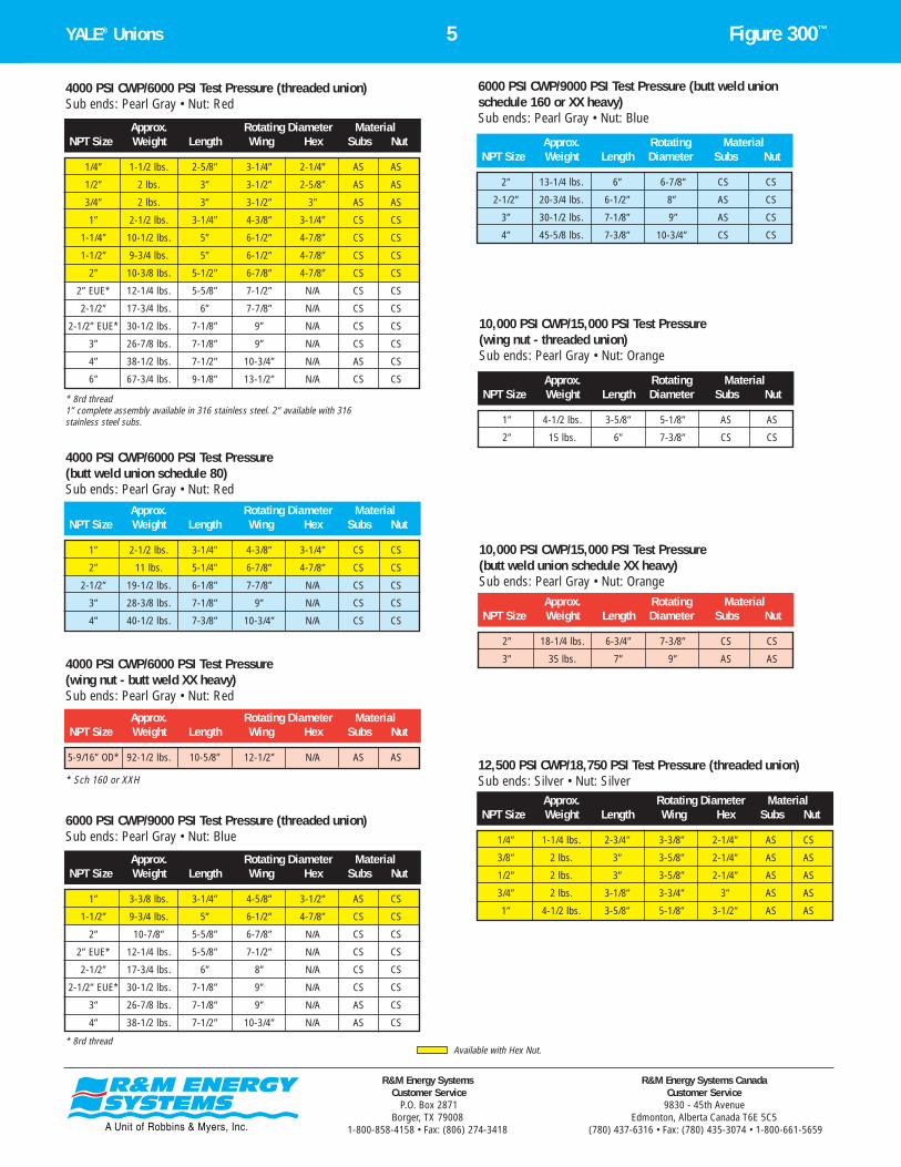
YALE® Unions 5 Figure 300™
R&M Energy Systems Customer Service
P.O. Box 2871Borger, TX 79008
1-800-858-4158 • Fax: (806) 274-3418
R&M Energy Systems CanadaCustomer Service
9830 - 45th Avenue Edmonton, Alberta Canada T6E 5C5
(780) 437-6316 • Fax: (780) 435-3074 • 1-800-661-5659
1/4” 1-1/2 lbs. 2-5/8” 3-1/4” 2-1/4” AS AS
1/2” 2 lbs. 3” 3-1/2” 2-5/8” AS AS
3/4” 2 lbs. 3” 3-1/2” 3” AS AS
1” 2-1/2 lbs. 3-1/4” 4-3/8” 3-1/4” CS CS
1-1/4” 10-1/2 lbs. 5” 6-1/2” 4-7/8” CS CS
1-1/2” 9-3/4 lbs. 5” 6-1/2” 4-7/8” CS CS
2” 10-3/8 lbs. 5-1/2” 6-7/8” 4-7/8” CS CS
2” EUE* 12-1/4 lbs. 5-5/8” 7-1/2” N/A CS CS
2-1/2” 17-3/4 lbs. 6” 7-7/8” N/A CS CS
2-1/2” EUE* 30-1/2 lbs. 7-1/8” 9” N/A CS CS
3” 26-7/8 lbs. 7-1/8” 9” N/A CS CS
4” 38-1/2 lbs. 7-1/2” 10-3/4” N/A AS CS
6” 67-3/4 lbs. 9-1/8” 13-1/2” N/A CS CS
Approx. Rotating Diameter MaterialNPT Size Weight Length Wing Hex Subs Nut
4000 PSI CWP/6000 PSI Test Pressure (threaded union)Sub ends: Pearl Gray • Nut: Red
* 8rd thread1” complete assembly available in 316 stainless steel. 2” available with 316stainless steel subs.
4000 PSI CWP/6000 PSI Test Pressure (wing nut - butt weld XX heavy)Sub ends: Pearl Gray • Nut: Red
5-9/16” OD* 92-1/2 lbs. 10-5/8” 12-1/2” N/A AS AS
Approx. Rotating Diameter MaterialNPT Size Weight Length Wing Hex Subs Nut
* Sch 160 or XXH
1” 3-3/8 lbs. 3-1/4” 4-5/8” 3-1/2” AS CS
1-1/2” 9-3/4 lbs. 5” 6-1/2” 4-7/8” CS CS
2” 10-7/8” 5-5/8” 6-7/8” N/A CS CS
2” EUE* 12-1/4 lbs. 5-5/8” 7-1/2” N/A CS CS
2-1/2” 17-3/4 lbs. 6” 8” N/A CS CS
2-1/2” EUE* 30-1/2 lbs. 7-1/8” 9” N/A CS CS
3” 26-7/8 lbs. 7-1/8” 9” N/A AS CS
4” 38-1/2 lbs. 7-1/2” 10-3/4” N/A AS CS
Approx. Rotating Diameter MaterialNPT Size Weight Length Wing Hex Subs Nut
6000 PSI CWP/9000 PSI Test Pressure (threaded union)Sub ends: Pearl Gray • Nut: Blue
* 8rd thread
2” 13-1/4 lbs. 6” 6-7/8” CS CS
2-1/2” 20-3/4 lbs. 6-1/2” 8” AS CS
3” 30-1/2 lbs. 7-1/8” 9” AS CS
4” 45-5/8 lbs. 7-3/8” 10-3/4” CS CS
Approx. Rotating MaterialNPT Size Weight Length Diameter Subs Nut
6000 PSI CWP/9000 PSI Test Pressure (butt weld unionschedule 160 or XX heavy)Sub ends: Pearl Gray • Nut: Blue
10,000 PSI CWP/15,000 PSI Test Pressure (wing nut - threaded union)Sub ends: Pearl Gray • Nut: Orange
1” 4-1/2 lbs. 3-5/8” 5-1/8” AS AS
2” 15 lbs. 6” 7-3/8” CS CS
Approx. Rotating MaterialNPT Size Weight Length Diameter Subs Nut
10,000 PSI CWP/15,000 PSI Test Pressure (butt weld union schedule XX heavy)Sub ends: Pearl Gray • Nut: Orange
2” 18-1/4 lbs. 6-3/4” 7-3/8” CS CS
3” 35 lbs. 7” 9” AS AS
Approx. Rotating MaterialNPT Size Weight Length Diameter Subs Nut
1/4” 1-1/4 lbs. 2-3/4” 3-3/8” 2-1/4” AS CS
3/8” 2 lbs. 3” 3-5/8” 2-1/4” AS AS
1/2” 2 lbs. 3” 3-5/8” 2-1/4” AS AS
3/4” 2 lbs. 3-1/8” 3-3/4” 3” AS AS
1” 4-1/2 lbs. 3-5/8” 5-1/8” 3-1/2” AS AS
Approx. Rotating Diameter MaterialNPT Size Weight Length Wing Hex Subs Nut
12,500 PSI CWP/18,750 PSI Test Pressure (threaded union)Sub ends: Silver • Nut: Silver
Approx. Rotating Diameter MaterialNPT Size Weight Length Wing Hex Subs Nut
4000 PSI CWP/6000 PSI Test Pressure (butt weld union schedule 80)Sub ends: Pearl Gray • Nut: Red
1” 2-1/2 lbs. 3-1/4” 4-3/8” 3-1/4” CS CS
2” 11 lbs. 5-1/4” 6-7/8” 4-7/8” CS CS
2-1/2” 19-1/2 lbs. 6-1/8” 7-7/8” N/A CS CS
3” 28-3/8 lbs. 7-1/8” 9” N/A CS CS
4” 40-1/2 lbs. 7-3/8” 10-3/4” N/A CS CS
Available with Hex Nut.

YALE® Unions 6 Figure 800™
R&M Energy Systems Customer Service
P.O. Box 2871Borger, TX 79008
1-800-858-4158 • Fax: (806) 274-3418
R&M Energy Systems CanadaCustomer Service
9830 - 45th Avenue Edmonton, Alberta Canada T6E 5C5
(780) 437-6316 • Fax: (780) 435-3074 • 1-800-661-5659
Figure 800™ “Quick-Stab” UnionsA long-time favorite in tank battery applications and production
hook-ups, the Figure 800 union is made extremely ruggedthroughout. Mating metal parts seal on arcs of a common circleand provide a pressure tight seal against gas or liquid. This design - the convex nose and concave seat - makes it easy to align andstab the union and simplifies starting the wing nut threads.
2” 5-3/4 lbs. 3-3/4” 5-3/4” DI DI
2-1/2” 9-1/2 lbs. 4-3/4” 6-3/4” DI DI
3” 12 lbs. 5” 8” DI DI
4” 21 lbs. 5-5/8” 9-3/4” DI DI
6” 42 lbs. 7” 13” DI DI
Approx. Rotating MaterialNPT Size Weight Length Diameter Subs Nut
500 PSI CWP/750 PSI Test Pressure (wing nut - threaded union)Sub ends: Black • Nut: Yellow
Also available in 2” 316 stainless steel (subs only)
1” 2 lbs. 2-5/8” 4-1/4” DI DI
1-1/4” 3-1/4 lbs. 3-3/8” 4-1/2” DI DI
1-1/2” 4-1/4 lbs. 3-5/8” 5” DI DI
2” 5-3/4 lbs. 3-3/4” 5-3/4” DI DI
2-1/2” 9-1/2 lbs. 4-3/4” 6-3/4” DI DI
3” 12 lbs. 5” 8” DI DI
4” 21 lbs. 5-5/8” 9-3/4” DI DI
6” 42 lbs. 7” 13” DI DI
Approx. Rotating MaterialNPT Size Weight Length Diameter Subs Nut
1000 PSI CWP/1500 PSI Test Pressure (wing nut - threaded union)Sub ends: Gray • Nut: Yellow
Also available in 2” 316 stainless steel (subs only)
1” 3 lbs. 3-1/2” 4-3/8” AS AS
1-1/2” 4-1/2 lbs. 3-5/8” 5-3/4” CS DI
2” 10-1/2 lbs. 5-1/8” 7” CS CS
2-1/2” 17-3/8 lbs. 6-1/4” 8” CS CS
3” 26-3/8 lbs. 7” 9-1/8” CS CS
4” 39 lbs. 7-7/8” 10-1/4” AS CS
6” 49-1/2 lbs. 7” 12-1/2” CS AS
Approx. Rotating MaterialNPT Size Weight Length Diameter Subs Nut
2500 PSI CWP/3750 PSI Test Pressure (wing nut - threaded union)Sub ends: Green • Nut: Pearl Gray
2” 11-1/4 lbs. 5-1/8” 7” CS CS
3” 27-1/2 lbs. 7-1/4” 9-1/8” CS CS
4” 39 lbs. 7” 10-1/4” CS CS
Approx. Rotating MaterialNPT Size Weight Length Diameter Subs Nut
2500 PSI CWP/3750 PSI Test Pressure (wing nut - butt weld union schedule 80)Sub ends: Green • Nut: Pearl Gray
1” 3 lbs. 3-1/2” 4-3/8” AS CS
1-1/2” 9-1/2 lbs. 4-1/2” 6-5/8” CS CS
2” 10-1/2 lbs. 5-1/8” 7” CS CS
2-1/2” 17-3/8 lbs. 6-1/4” 8” CS CS
3” 26-3/8 lbs. 7” 9-1/8” CS CS
4” 39 lbs. 7-7/8” 10-1/4” AS CS
Approx. Rotating MaterialNPT Size Weight Length Diameter Subs Nut
4000 PSI CWP/6000 PSI Test Pressure (wing nut - threaded union)Sub ends: Red • Nut: Pearl Gray
2” 11-1/4 lbs. 5-1/8” 7” CS CS
3” 27-1/2 lbs. 7” 9-1/8” CS CS
Approx. Rotating MaterialNPT Size Weight Length Diameter Subs Nut
4000 PSI CWP/6000 PSI Test Pressure (wing nut - butt weld union schedule 80)Sub ends: Red • Nut: Pearl Gray
1” 3-1/8 lbs. 3-1/2” 4-5/8” AS CS
Approx. Rotating MaterialNPT Size Weight Length Diameter Subs Nut
6000 PSI CWP/9000 PSI Test Pressure (wing nut - threaded union)Sub ends: Blue • Nut: Pearl Gray
1” 4-1/2 lbs. 3-1/2” 5-1/8” AS AS
Approx. Rotating MaterialNPT Size Weight Length Diameter Subs Nut
10,000 PSI CWP/15,000 PSI Test Pressure (wing nut - threaded union)Sub ends: Orange • Nut: Pearl Gray
Best choice for steam applications

YALE® Unions 7 Figure 800R™
R&M Energy Systems Customer Service
P.O. Box 2871Borger, TX 79008
1-800-858-4158 • Fax: (806) 274-3418
R&M Energy Systems CanadaCustomer Service
9830 - 45th Avenue Edmonton, Alberta Canada T6E 5C5
(780) 437-6316 • Fax: (780) 435-3074 • 1-800-661-5659
Figure 800R™ “Quick-Stab” UnionsO-Ring Seal
This is a maximum service union designed for severe conditions where pressureextremes or vacuum occur. Also the Figure 800R is commonly used in drilling applications (e.g., standby manifolds). This union offers the double security of a metal-to-metal seal plus an O-ring seal, and is available for pressures from 1000 to 10,000 PSI CWP.
8” 91 lbs. 10-7/8” 16” CS DI
Approx. Rotating MaterialNPT Size Weight Length Diameter Subs Nut
1000 PSI CWP/1500 PSI Test Pressure (wing nut - threaded union)Sub ends: Gray • Nut: Yellow
2” 10-1/2 lbs. 5-1/8” 7” CS CS
2-1/2” 17-3/8 lbs. 6-1/4” 8” CS CS
3” 26-3/8 lbs. 7” 9-1/8” CS CS
4” 39 lbs. 7-7/8” 10-1/4” AS CS
6” 49-1/2 lbs. 7” 12-1/2” CS AS
Approx. Rotating MaterialNPT Size Weight Length Diameter Subs Nut
2500 PSI CWP/3750 PSI Test Pressure (wing nut - threaded union)Sub ends: Green • Nut: Pearl Gray
2” 11-1/4 lbs. 5-1/8” 7” CS CS
3” 27-1/2 lbs. 7-1/4” 9-1/8” CS CS
4” 39 lbs. 7” 10-1/4” CS CS
6” 55 lbs. 7” 12-1/2” CS AS
Approx. Rotating MaterialNPT Size Weight Length Diameter Subs Nut
2500 PSI CWP/3750 PSI Test Pressure (wing nut - butt weld union schedule 80)Sub ends: Green • Nut: Pearl Gray
1-1/2” 9-1/2 lbs. 4-1/2” 6-5/8” CS CS
2” 10-1/2 lbs. 5-1/8” 7” CS CS
2-1/2” 17-3/8 lbs. 6-1/4” 8” CS CS
3” 26-3/8 lbs. 7” 9-1/8” CS CS
4” 39 lbs. 7-7/8” 10-1/4” AS CS
5-1/2” OD* 48-3/4 lbs. 10” 11-3/4” CS AS
5-9/16 OD 49 lbs. 10” 11-3/4” CS AS
7-5/8” OD* 112-1/2 lbs. 12-1/2” 15-1/2” CS DI
Approx. Rotating MaterialNPT Size Weight Length Diameter Subs Nut
4000 PSI CWP/6000 PSI Test Pressure (wing nut - threaded union)Sub ends: Red • Nut: Pearl Gray
* 8rd thread
2” 10-1/2 lbs. 5-1/8” 7” CS CS
3” 27-1/2 lbs. 7-1/4” 9-1/8” CS CS
4” 39 lbs. 7” 10-1/4” CS CS
Approx. Rotating MaterialNPT Size Weight Length Diameter Subs Nut
4000 PSI CWP/6000 PSI Test Pressure(wing nut - butt weld union schedule 80)Sub ends: Red • Nut: Pearl Gray
1-1/2” 9-1/2 lbs. 4-1/2” 6-5/8” CS CS
2” 16-1/4 lbs. 5-5/8” 7-5/8” CS CS
2-1/2” 17-1/4 lbs. 6-1/4” 8” AS CS
3” 26 lbs. 7” 9-1/8” AS CS
4” 38-1/2 lbs. 7-3/4” 10-1/2” AS CS
5-1/2” OD* 77-1/2 lbs. 10-1/4” 12-1/2” AS AS
Approx. Rotating MaterialNPT Size Weight Length Diameter Subs Nut
6000 PSI CWP/9000 PSI Test Pressure (wing nut - threaded union)Sub ends: Blue • Nut: Pearl Gray
* 8rd thread
** 93-3/4 lbs. 10-1/4” 12-1/2” AS AS
** 5-9/16” butt weld tail sub schedule 160 or XX hvy X 4” NPT threaded sub
Approx. Rotating MaterialNPT Size Weight Length Diameter Subs Nut
6000 PSI CWP/9000 PSI Test Pressure (wing nut - specialcombination union) For mudline stand pipe assemblySub ends: Blue • Nut: Pearl Gray
2” 18-1/2 lbs. 5-3/4” 7-5/8” CS CS
2-1/2” 21 lbs. 5-1/8” 8” AS CS
3” 30 lbs. 7-1/4” 9-1/8” AS CS
4” 44-1/4 lbs. 7” 10-1/2” CS CS
5-9/16” OD 91-1/2 lbs. 10-1/8” 12-1/2” CS AS
6” 97-5/8 lbs. 9” 14-1/2” AS CS
Approx. Rotating MaterialNPT Size Weight Length Diameter Subs Nut
6000 PSI CWP/9000 PSI Test Pressure(wing nut - butt weld union schedule XX hvy or 160)Sub ends: Blue • Nut: Pearl Gray
1-1/2” 9-1/2 lbs. 4-1/2” 6-5/8” CS CS
2” 16-1/4 lbs. 5-5/8” 7-5/8” CS CS
3” 30-1/2 lbs. 7-1/8” 9-1/2” AS AS
Approx. Rotating MaterialNPT Size Weight Length Diameter Subs Nut
10,000 PSI CWP/15,000 PSI Test Pressure(wing nut - threaded union)Sub ends: Orange • Nut: Pearl Gray
2” 18-1/2 lbs. 5-3/4” 7-5/8” CS CS
3” 34-1/2 lbs. 6-3/8” 9-1/2” AS AS
Approx. Rotating MaterialNPT Size Weight Length Diameter Subs Nut
10,000 PSI CWP/15,000 PSI Test Pressure(wing nut - butt weld union schedule XX hvy)Sub ends: Orange • Nut: Pearl Gray

YALE® Unions 8 Figure 110™ & 300I™
R&M Energy Systems Customer Service
P.O. Box 2871Borger, TX 79008
1-800-858-4158 • Fax: (806) 274-3418
R&M Energy Systems CanadaCustomer Service
9830 - 45th Avenue Edmonton, Alberta Canada T6E 5C5
(780) 437-6316 • Fax: (780) 435-3074 • 1-800-661-5659
Only Yale offers two models of insulating unions in either wing or hex nut configurations. Both unions feature the “flat-face”design for easy removal and prevent electrolytic corrosion in lines by breaking the flow of current through the system.
Figure 110™
2” 6-1/2 lbs. 3-3/4” 5-3/4” 4-3/4” DI DI
3” 11-1/4 lbs. 5” 8” N/A DI DI
Approx. Rotating Diameter MaterialNPT Size Weight Length Wing Hex Subs Nut
500 PSI CWP/750 PSI Test Pressure(threaded union)Sub ends: Maroon • Nut: Maroon
1” 1-1/2 lbs. 2-5/8” 4-1/4” 2-3/4” CS DI
1-1/2” 4 lbs. 3-5/8” 5” 4-1/8” DI DI
2” 6-1/2 lbs. 3-3/4” 5-3/4” 4-3/4” DI DI
2-1/2” 8-3/8 lbs. 4-5/8” 7” N/A DI DI
3” 11-1/4 lbs. 5” 8” N/A DI DI
4” 19 lbs. 5-3/4” 10” N/A DI DI
Approx. Rotating Diameter MaterialNPT Size Weight Length Wing Hex Subs Nut
1000 PSI CWP/1500 PSI Test Pressure(threaded union)Sub ends: Maroon • Nut: White
1/4” 1/2 lbs. 2-1/8” N/A 1-5/8” CS CS
3/8” 3/4 lbs. 2-3/8” N/A 2-1/4” CS CS
1/2” 3/4 lbs. 2-3/8” N/A 2-1/4” CS CS
3/4” 1-1/4 lbs. 2-1/2” N/A 2-3/8” CS CS
1” 2-1/2 lbs. 3-1/4” 4-5/8” 3-3/8” CS CS
1-1/4” 10 lbs. 5-1/8” 6-1/2” N/A CS CS
1-1/2” 9-3/8 lbs. 5-1/8” 6-1/2” N/A CS CS
2” 6-1/2 lbs. 3-3/4” 6-1/4” 4-7/8” CS CS
3” 12-1/2 lbs. 5-1/8” 8” N/A CS CS
4” 21 lbs. 5-3/4” 9-1/2” N/A CS CS
Approx. Rotating Diameter MaterialNPT Size Weight Length Wing Hex Subs Nut
2500 PSI CWP/3750 PSI Test Pressure(threaded union)Sub ends: Orange • Nut: Orange
1” 2-1/2 lbs. 3-1/4” 4-5/8” 3-3/8” CS CS
2” 13-1/2 lbs. 6-1/8” 7-3/8” N/A CS CS
3” 25-3/4 lbs. 7-1/4” 9” N/A CS CS
Approx. Rotating Diameter MaterialNPT Size Weight Length Wing Hex Subs Nut
4000 PSI CWP/6000 PSI Test Pressure (threaded union)Sub ends: Brown • Nut: Brown
1/4” 1-1/4 lbs. 2-3/4” N/A 2-1/4” AS AS
1/2” 2 lbs. 3-3/8” N/A 3” AS AS
Approx. Rotating Diameter MaterialNPT Size Weight Length Wing Hex Subs Nut
6000 PSI CWP/9000 PSI Test Pressure (threaded union)Sub ends: Blue • Nut: Blue
Figure 110™ Insulating UnionsRecommended for use in flow lines to isolate for cathodic
protection. The metal parts are separated by non-conductorgaskets that are impervious to flow, seepage and resistant toacids, chemicals and temperatures encountered in normal service. Dual O-rings provide a pressure seal. Maximum temperature is 250˚ F.
Figure 300I™ Insulating UnionsAn “engineering” plastic is injection molded onto the tail sub of this union to separate the metal
parts and prevent current flow. The plastic is an impact resistant material rated up to 120˚ F.
2” 5-1/2 lbs. 3-3/4” 5-3/4” 4-7/8” DI DI
Approx. Rotating Diameter MaterialNPT Size Weight Length Wing Hex Subs Nut
1000 PSI CWP/1500 PSI Test Pressure (threaded union)Sub ends: Yellow • Nut: Yellow
2” 7 lbs. 3-3/4” 6-1/8” 4-7/8” CS CS
Approx. Rotating Diameter MaterialNPT Size Weight Length Wing Hex Subs Nut
2500 PSI CWP/3750 PSI Test Pressure(threaded union)Sub ends: Pearl Gray • Nuts: Pearl Gray
Figure 300I™
Available with Hex Nut.

YALE® Unions 9 Figure 210™
R&M Energy Systems Customer Service
P.O. Box 2871Borger, TX 79008
1-800-858-4158 • Fax: (806) 274-3418
R&M Energy Systems CanadaCustomer Service
9830 - 45th Avenue Edmonton, Alberta Canada T6E 5C5
(780) 437-6316 • Fax: (780) 435-3074 • 1-800-661-5659
2” 5-3/8 lbs. 2-5/8” 5-3/4” DI CS
3” 11-3/8 lbs. 3-5/8” 8” DI AS
4” 21-1/2 lbs. 4-1/4” 9” DI CS
6” 28-3/8 lbs. 4-1/8” 11-1/2” DI CS
Approx. Rotating MaterialNPT Size Weight Length Diameter Subs Nut
1000 PSI CWP/1500 PSI Test Pressure Sub end: Yellow • Cap: Gray
2” 5-1/2 lbs. 2-3/4” 5-3/4” CS CS
3” 11-7/8 lbs. 3-3/4” 8” CS CS
4” 22-1/8 lbs. 4-3/8” 9” CS CS
Approx. Rotating MaterialNPT Size Weight Length Diameter Subs Nut
2500 PSI CWP/3750 PSI Test Pressure Sub end: Pearl Gray • Cap: Green
2” 7 lbs. 3-1/4” 5-3/4” CS CS
3” 15 lbs. 4-1/4” 8” CS CS
4” 27 lbs. 5” 9” CS CS
Approx. Rotating MaterialNPT Size Weight Length Diameter Subs Nut
2500 PSI CWP/3750 PSI Test Pressure (butt weld union schedule 80)Sub end: Pearl Gray • Cap: Green
2” 12 lbs. 4” 6-1/2” CS AS
3” 26 lbs. 4-1/2” 9-1/4” CS AS
Approx. Rotating MaterialNPT Size Weight Length Diameter Subs Nut
4000 PSI CWP/6000 PSI Test Pressure (butt weld union schedule 80)Sub end: Pearl Gray • Cap: Red
2” 9-3/4 lbs. 3-7/8” 6-1/2” CS CS
Approx. Rotating MaterialNPT Size Weight Length Diameter Subs Nut
6000 PSI CWP/9000 PSI Test Pressure Sub end: Pearl Gray • Cap: Blue
2” 14 lbs. 4” 6-1/2” CS AS
3” 29 lbs. 5” 9-1/4” CS AS
Approx. Rotating MaterialNPT Size Weight Length Diameter Subs Nut
6000 PSI CWP/9000 PSI Test Pressure (butt weld union schedule XX hvy or 160)Sub end: Pearl Gray • Cap: Blue
2” 9-1/4 lbs. 3-7/8” 6-1/2” CS CS
3” 27-1/8 lbs. 5” 9-1/4” CS CS
Approx. Rotating MaterialNPT Size Weight Length Diameter Subs Nut
4000 PSI CWP/6000 PSI Test Pressure Sub end: Pearl Gray • Cap: Red
Figure 210™ Threaded Blanking UnionsDesigned for use on manifolds, jumper assemblies and other
installations where a blank cap connection is required. By using a tailsub and wing nut from a Figure 300, the Figure 210 is easily convertedinto a conventional union through which flow may be maintained. Thecap is furnished blank as standard, but can be drilled and tapped for a1/8”-1” NPT for a bleeder plug.

YALE® Unions 10 Figure 310™
R&M Energy Systems Customer Service
P.O. Box 2871Borger, TX 79008
1-800-858-4158 • Fax: (806) 274-3418
R&M Energy Systems CanadaCustomer Service
9830 - 45th Avenue Edmonton, Alberta Canada T6E 5C5
(780) 437-6316 • Fax: (780) 435-3074 • 1-800-661-5659
1”* 2 lbs. 2-5/8” 4-1/4” 2-7/8” CS DI
2” 6-1/2 lbs. 3-3/4” 5-3/4” 4-7/8” DI DI
Approx. Rotating Diameter MaterialNPT Size Weight Length Wing Hex Subs Nut
1000 PSI CWP/1500 PSI Test Pressure (threaded union)Sub ends: Gray • Nut: Gray
1/2” 2 lbs. 3” 3-5/8” 2-1/4” AS AS
3/4” 2-1/8 lbs. 3-1/8” 3-3/4” 3” AS AS
1” 2-1/2 lbs. 3-1/2” 4-1/2” N/A AS CS
Approx. Rotating Diameter MaterialNPT Size Weight Length Wing Hex Subs Nut
4000 PSI CWP/6000 PSI Test Pressure (threaded union)Sub ends: Cadmium Plated • Nut: Cadmium Plated
Figure 310™ Threaded Choke UnionsPermits reduction of downstream pressure or volume.
Through use of different size orifice plates, pressureand/or volume can be regulated without the use of amore expensive orifice fitting. The union may be usedupstream of a pressure reducing regulator in order toobtain a primary pressure reduction, or it may be used tocontrol flow where metering is not required. Orificeplates are 304 stainless steel and are regularly furnishedin sizes from 1/16” up to the full inside diameter of thepipe bore.
* Cadmium plated.
Figure 310 Threaded Choke Unions are sold without orifice plates. Orifice plates must be ordered separately.
Notes:
Available with Hex Nut.

YALE® Unions 11 Butt Weld Union Bore Diameters
R&M Energy Systems Customer Service
P.O. Box 2871Borger, TX 79008
1-800-858-4158 • Fax: (806) 274-3418
R&M Energy Systems CanadaCustomer Service
9830 - 45th Avenue Edmonton, Alberta Canada T6E 5C5
(780) 437-6316 • Fax: (780) 435-3074 • 1-800-661-5659
Nominal Standard Schedule Extra Heavy Schedule Schedule Double Extra Size 40 (XH) 80 160 Heavy (XXH)
Butt Weld Bore Diameters
1” 1.049” 1.049” .957” .957” .815” .599”
1-1/2” 1.610” 1.610” 1.500” 1.500” 1.338” 1.100”
2” 2.067” 2.067” 1.939” 1.939” 1.687” 1.503”
2-1/2” 2.469” 2.469” 2.323” 2.323” 2.125” 1.771”
3” 3.068” 3.068” 2.900” 2.900” 2.624” 2.300”
4” 4.026” 4.026” 3.826” 3.826” 3.438” 3.152”
5” 5.047” 5.047” 4.813” 4.813” 4.313” 4.063”(5-9/16” OD)
6” 6.065” 6.065” 5.761” 5.761” 5.187” 4.897”

Standard Service
YALE® Unions 12 Pressure Ratings
R&M Energy Systems Customer Service
P.O. Box 2871Borger, TX 79008
1-800-858-4158 • Fax: (806) 274-3418
R&M Energy Systems CanadaCustomer Service
9830 - 45th Avenue Edmonton, Alberta Canada T6E 5C5
(780) 437-6316 • Fax: (780) 435-3074 • 1-800-661-5659
Working TestNo. Pressure Pressure(1) Pressure 1/4” 1/2” 3/4” 1” 1-1/4” 1-1/2” 2” 2-1/2” 3” 4” 5” 6” 8” Notes
Pressure Rating
110™ 500 750 NR NR 71000 1500 NR NR 72500 3750 NR NR 74000 6000 NR NR 76000 9000 NR NR 7
210™ 1000 1500 NR NR 2500 3750 1500 2250 SG SG SG NR 4,54000 6000 2500 3750 SG SG SG 46000 9000 NR NR
300™ 500 750 NR NR1000 1500 NR NR2500 3750 1500 2250 NR NR NR NR NR NR SG SG SG SG NR 4,54000 6000 2500 3750 NR NR SG SG SG SG SG NR NR 4,56000 9000 4000 6000 NR NR SG SG SG SG NR 3,4,6
10,000 15,000 5000 7500 NR SG SG 3,4,612,500 18,750 NR NR
300I™ 1000 1500 NR NR 82500 3750 NR NR 8
310™ 1000 1500 NR NR4000 6000 2500 3750 NR NR NR SG 4
800™ 500 750 NR NR 1000 1500 NR NR2500 3750 NR NR4000 6000 NR NR6000 9000 NR NR
10,000 15,000 NR NR
800R™ 1000 1500 NR NR2500 3750 1500 2250 SG SG SG SG NR 4,54000 6000 2500 3750 SG SG SG SG SG NR 4,56000 9000 4000 6000 NR SG SG SG SG NR 3,4,6
10,000 15,000 5000 7500 NR SG SG 3,4,6
Sour Gas Service
WorkingPressure
NR-Not Recommended for Sour Gas ServiceSG-Recommended for Sour Gas ServiceNotes:(1) Test Pressure - Indicates a union’s capability in a factory, non-shock, cold, hydrostatictest with no external loads.(2) Unions rated for sour gas service are manufactured of materials, at the hardness levelsprescribed, as recommended in NACE MR-01-75 for use in sour environments.(3) Hardness test must be performed and be RC 22 or less prior to sale for sour gas service.
(4) Viton O-rings are furnished with sour gas unions. However, R&M Energy Systemsdoes not warrant the performance of any elastomer for sour gas service.(5) Line Pipe (NPT) threads are not recommended for sour gas service above 4 inchesnominal pipe size. Specify butt weld end connections.(6) Butt weld only for sour gas service - line pipe threads are not recommended forsour gas service at this pressure rating.(7) Maximum temperature for Figure 110 insulating union is 250˚ F.(8) Maximum temperature for Figure 300I insulating union is 120˚ F.
N O M I N A L P I P E S I Z E

YALE® Unions 13 Metric Conversion Chart
API ROD, TUBING & LINE PIPE SPECIFICATIONS
ROD O.D.
Inches Millimeters*1/2” 135/8” 163/4” 197/8” 221” 25
1-1/8” 291-1/4” 321-3/8” 351-1/2” 381-3/4” 45
WORKING PRESSURE
* Rounded to nearest millimeter.
API TUBING
External Upset Non-Upset
Nominal O.D. I.D. Lbs. Kgs. Threads O.D. I.D. Lbs. Kgs. ThreadsSize In MM In MM Per Ft. Per Meter Per Inch In MM In MM Per Ft. Per Meter Per Inch
3/4” 1.050 26.7 .824 20.9 1.2 1.8 10rd 1.050 26.7 .824 20.9 1.1 1.7 10rd
1” 1.315 33.4 1.049 26.6 1.8 2.7 10rd 1.315 33.4 1.049 26.6 1.7 2.5 10rd
1-1/4” 1.660 42.2 1.380 35.0 2.4 3.6 10rd 1.660 42.2 1.380 35.0 2.3 3.4 10rd
1-1/2” 1.900 48.3 1.610 40.9 2.9 4.3 10rd 1.900 48.3 1.610 40.9 2.8 4.1 10rd
2” 2-3/8 60.3 1.995 50.7 4.7 7.0 8rd 2-3/8 60.3 1.995 50.7 4.6 6.8 10rd
2-1/2” 2-7/8 73.0 2.441 62.0 6.5 9.7 8rd 2-7/8 73.0 2.441 62.0 6.4 9.5 10rd
3” Not Specified - See Note Below
3-1/2” 3-1/2 88.9 2.992 76.0 9.3 13.8 8rd 3-1/2 88.9 2.992 76.0 9.2 13.7 10rd
4” 4.000 101.6 3.476 88.3 11.0 16.4 8rd 4.000 101.6 3.548 90.1 9.5 14.1 8rd
4-1/2” 4.500 114.3 3.958 100.5 12.8 19.0 8rd 4.500 114.3 3.958 100.5 12.6 18.8 8rd
API LINE PIPE (LP)
Standard Wall ThicknessNominal O.D. I.D. Lbs. Kgs. Threads
Size In MM In MM Per Ft. Per Meter Per Inch3/4” 1.050 26.7 .824 20.9 1.1 1.7 14V1” 1.315 33.4 1.049 26.6 1.7 2.5 11-1/2V
1-1/4” 1.660 42.2 1.380 35.0 2.3 3.4 11-1/2V1-1/2” 1.900 48.3 1.610 40.9 2.8 4.1 11-1/2V
2” 2-3/8 60.3 2.067 52.5 3.8 5.6 11-1/2V2-1/2” 2-7/8 73.0 2.469 62.7 5.9 8.8 8V
3” 3-1/2 88.9 3.068 77.9 7.7 11.5 8V3-1/2” 4.000 101.6 3.548 90.1 9.35 13.8 8V
4” 4.500 114.3 4.026 102.3 11.0 16.4 8V
• Round (rd) threads are used for casing & tubing.• V threads are used for line pipe.• EUE = External Upset
• NUE = Non-Upset • 3” tubing is not specified (N/S) by API, but 3” & 3-1/2” are frequently used
interchangeably when referring to 3-1/2” API tubing.
Notes:
PSI kPa
1500 10,340
2000 13,800
2500 17,250
3000 20,700
4000 27,600
6000 41,400
Inches Millimeters Inches Millimeters
N/A N/A N/A N/A1-1/4” 31.75 1-1/2” 38.101-1/2” 38.10 1-5/8” 41.281-5/8” 41.28 1-13/16” 46.04
2” 50.80 2-3/16” 55.56— — 2-3/8” 60.33
ROD & ROD COUPLING DIMENSIONSSlimhole O.D. Full Size O.D.
R&M Energy Systems Customer Service
P.O. Box 2871Borger, TX 79008
1-800-858-4158 • Fax: (806) 274-3418
R&M Energy Systems CanadaCustomer Service
9830 - 45th Avenue Edmonton, Alberta Canada T6E 5C5
(780) 437-6316 • Fax: (780) 435-3074 • 1-800-661-5659
TEMPERATURE CONVERSION˚C = 5/9 (˚ F-32)
To convert Fahrenheit degrees into Celsius, subtract 32, multiply by 5 and divide by 9.

YALE® Unions 14 Metric Conversion Chart
R&M Energy Systems Customer Service
P.O. Box 2871Borger, TX 79008
1-800-858-4158 • Fax: (806) 274-3418
R&M Energy Systems CanadaCustomer Service
9830 - 45th Avenue Edmonton, Alberta Canada T6E 5C5
(780) 437-6316 • Fax: (780) 435-3074 • 1-800-661-5659
MOST COMMON API CASING
Long & Short Short LongNominal O.D. Lbs. Per Kgs. Per I.D. Coupling O.D. Coupling Length Coupling Length
In MM Ft. Meter In MM In MM In MM In MM
9.50 14.1 4.090 103.94-1/2” 114.3 11.60 17.3 4.000 101.6 5.000 127.0 6-1/4 158.8 7 177.8
13.50 20.1 3.920 99.615.10 22.5 3.826 97.213.00 19.3 5.044 128.114.00 20.8 5.012 127.3
5-1/2” 139.7 15.50 23.1 4.950 125.7 6.050 153.7 6-3/4 171.5 8 203.217.00 25.3 4.892 124.320.00 29.8 4.778 121.423.00 34.2 4.670 118.617.00 25.3 6.135 155.820.00 29.8 6.049 153.6
6-5/8” 168.3 24.00 35.7 5.921 150.4 7.390 187.7 7-1/4 184.2 8-3/4 222.328.00 41.7 5.791 147.132.00 47.6 5.675 144.117.00 25.3 6.538 166.120.00 29.8 6.456 164.023.00 34.2 6.366 161.7
7” 177.8 26.00 38.7 6.276 159.4 7.656 194.5 7-1/4 184.2 9 228.629.00 43.2 6.184 157.132.00 47.6 6.094 154.835.00 52.1 6.004 152.538.00 56.6 5.920 150.420.00 29.8 7.125 181.024.00 35.7 7.025 178.4
7-5/8” 193.7 26.40 39.3 6.969 177.0 8.500 215.9 7-1/2 190.5 9-1/4 235.029.70 44.2 6.875 174.633.70 50.2 6.765 171.839.00 58.0 6.625 168.324.00 35.7 8.097 205.728.00 41.7 8.017 203.632.00 47.6 7.921 201.2
8-5/8” 219.1 36.00 53.6 7.825 198.8 9.625 244.5 7-3/4 196.9 10 254.040.00 59.5 7.725 196.244.00 65.5 7.625 193.749.00 72.9 7.511 190.829.30 43.6 9.063 230.232.30 48.1 9.001 228.636.00 53.6 8.921 226.6
9-5/8” 244.5 40.00 59.5 8.835 224.4 10.625 269.9 7-3/4 196.9 10-1/2 266.743.50 64.7 8.755 222.447.00 69.9 8.681 220.553.50 79.6 8.535 216.832.75 48.7 10.192 258.940.50 60.3 10.050 255.345.50 67.7 9.950 252.7
10-3/4 273.1 51.00 75.9 9.850 250.2 11.750 298.5 8 203.2 N/A N/A55.50 82.6 9.760 247.960.70 90.3 9.660 245.465.70 97.8 9.560 242.8
• All API casing threads are 8rd threads per inch.• Casing threads are either long thread or short thread.• Most Hercules® wellheads have short threads.
• It is permissible to put short casing threads into long couplings, but not permissible to put long casing threads into short couplings.
Notes:

1. ACCEPTANCE1.1 All orders are subject to final acceptance by R&M ENERGY SYSTEMS L.P.
(DBA and hereinafter referred to as R&M ENERGY SYSTEMS).
2. F.O.B. POINT2.1 All shipments are F.O.B. R&M ENERGY SYSTEMS Point of Origin or other
designated shipping point.
3. PRICES3.1 All quotations are made for prompt acceptance and any terms quoted
therein are subject to change without notice after thirty (30) days from the date of quotation unless specifically stated otherwise on the quotation.Prices or escalation formulas in effect at time of shipment will apply unless otherwise stated in writing.
3.2 Prices are F.O.B. Point of Origin. R&M ENERGY SYSTEMS reserves theright to invoice customer for any and all finished material ready for ship-ment, when held at customer’s request or for other reasons beyond R&M ENERGY SYSTEMS’ control. Seller reserves the right to place a service charge on past due accounts at the highest rate permitted by law. Every Sales, Use, Excise or other tax and any charge imposed by law or Common practice to include custom duties, consular fees, insurance charges and other comparable charges to be borne by customer. Prices are in U.S. Dollars.
3.3 All orders are subject to any Federal, State or other Government Regulation that may be in effect or later become effective.
3.4 Charges for Field Installation of Equipment not available during manufacturingprocess will be borne by Customer unless otherwise stated in writing.
4. MINIMUM BILLING4.1 Minimum billing of $25 net will be charged per order on any partial
shipment requested by customer.4.2 Change orders and/or “add on” supplements are subject to additional
billings commensurate with the cost and will receive individual consideration insofar as minimum billing, freight allowance and discount are concerned.
5. DELIVERIES5.1 All promises of shipment are estimated as closely as possible based on
the availability of materials and capacity at the time and are expressly subject to change due to delays resulting from strikes, differences with workmen, labor troubles, acts of God, Governmental acts and regulations,war or war conditions, riots or civil commotion, sabotage, fires, floods, explosions or other accidents, or to delays to carriers or of subcon-tractors or in receipt of materials, or to delays occasioned by or arising in connection with obligations to other cause or causes (whether or not of the same general character as those herein specifically enumerated) beyond R&M ENERGY SYSTEMS’ reasonable control.
5.2 If additional information or drawing approval is required, promise of shipment will date from receipt of same.
6. DESIGN6.1 R&M ENERGY SYSTEMS reserves the right to make changes in designs
and/or materials without notice.
7. CANCELLATIONS7.1 Orders accepted by R&M ENERGY SYSTEMS are not subject to
cancellation by customer except with the consent of R&M ENERGY SYSTEMS and upon terms which will indemnify R&M ENERGY SYSTEMSagainst loss or damage occasioned by such cancellation.
8. INSPECTION8.1 Final inspection and acceptance of products must be made at
R&M ENERGY SYSTEMS’ plant and shall be conclusive except as regards latent defects.
8.2 Customer’s representatives may inspect at the plant during working hours prior to shipment in such manner as will not interfere with operations.
9. ENGINEERING AND SERVICE9.1 Upon request, R&M ENERGY SYSTEMS may provide engineering and/
or technical information about its products and their uses; and if feasible may provide personnel to assist buyer in effecting field installationand/or field service.
9.2 Such information service, or assistance so provided, whether with or without charge, shall be advisory only, and buyer agrees to hold R&M ENERGY SYSTEMS harmless from claims for loss from any cause resulting from such advisory or service activity.
10. WARRANTY10.1 THIS WARRANTY IS IN LIEU OF ALL OTHER WARRANTIES,
EXPRESSED OR IMPLIED, INCLUDING ANY IMPLIED WARRANTY OF MERCHANTABILITY OR FITNESS.
10.2 R&M ENERGY SYSTEMS warrants that all products manufactured by it and all repair work performed by it shall be free from defects in workmanship and material when these products are used within the service and pressure range from which they were manufactured. Such warranty shall be binding upon R&M ENERGY SYSTEMS in respect to products for a period of one year from shipment of such products and in respect to repair work for a period of 60 days from completion of such repairs and applies only to materials furnished and work performed in the repair operation.
10.3 If, at any time within such periods, it is established to the satisfaction of R&M ENERGY SYSTEMS that any product manufactured by R&M ENERGY SYSTEMS was defective at time of shipment or any repair work performed by R&M ENERGY SYSTEMS was defective, R&M ENERGY SYSTEMS, at its option, shall repair or exchange such item, F.O.B. place of manufacture or repair or other R&M ENERGY SYSTEMS designated shipping point, or refund the price paid.
10.4 It is understood that the liability of R&M ENERGY SYSTEMS shall be limited to such repair or replacement and that R&M ENERGY SYSTEMS SHALL NOT BE LIABLE FOR ANY DIRECT, INDIRECT, INCIDENTAL OR CONSEQUENTIAL DAMAGES ARISING OUT OF ANY DEFECTS OR FROM ANY CAUSE WHATSOEVER.
10.5 This warranty does not cover deterioration by corrosion or aging of non-metallic parts, including stress corrosion or any other cause of failure other than defects in workmanship and materials.
10.6 Unless repairs to, alterations of, or work done on said products by the buyershall be specifically authorized in writing by R&M ENERGY SYSTEMS, any warranty applicable thereto shall become null and void.
10.7 R&M ENERGY SYSTEMS does not warrant the performance of any elastomer subjected to severe service due to temperature and/or chemical environment.
11. FREIGHT11.1 Any freight allowance applies to materials manufactured only by R&M
ENERGY SYSTEMS. Delivery by carrier will be at customer’s risk.
12. PATENT INFRINGEMENT12.1 The seller shall not be liable for any damage or costs for any
infringement of patents for products which are produced to buyer’s specifications and buyer shall assume all responsibility for and save seller harmless from any and all damages, cost, royalties and claims arising out of charges of any infringement.
13. GENERAL13.1 Acceptance of buyer’s order is expressly conditional upon buyer’s
acceptance of the foregoing terms and conditions of sale. Any additionalor different terms proposed by customer are not acceptable unless expressly agreed to in writing by R&M ENERGY SYSTEMS.
R&M ENERGY SYSTEMSTERMS & CONDITIONS OF SALE
The above supersedes all “Terms & Conditions of Sale” prior to 3/3/97.
15

Web Site: www.rmenergy.com
© 2004 by R&M Energy Systems.® YALE is a registered trademark of R&M Energy Systems.™ Figure 110, 210, 300, 300I, 310, 800 and 800R are trademarks of R&M Energy Systems.
Printed in U.S.A.904
R&M Energy SystemsCustomer Service
P.O. Box 2871Borger, Texas, U.S.A. 79008-2871
(800) 858-4158Fax: (806) 274-3418
R&M Energy Systems CanadaCustomer Service9830 - 45th Avenue
Edmonton, Alberta, Canada T6E 5C5(800) 661-5659(780) 437-6316
Fax: (780) 435-3074
E-Mail: [email protected]