Embed Size (px)
Citation preview

Table of contents
About Veya Investments Limited ................................................................................................................2
List of works performed by the company ................................................................................................3
Gas-turbine units. General information ....................................................................................................4
Gas-pumping units. General information ................................................................................................5
Standard engines used for gas-turbine units driving ...........................................................................6
Design and technical data of a standard gas turbine engine .............................................................8
Engines used in industrial units ................................................................................................................20
Gas-pumping units. General information ..............................................................................................31
Gas-pumping units for line compressor stations .................................................................................33
Gas-pumping units for booster compressor stations .........................................................................35
Gas-pumping units for underground gas storages ............................................................................36
Electric power plants based on gas-turbine engines .........................................................................37
Low-powered electric power plants – up to 10 MW ...........................................................................37
High-capacity electric power plant – from 10 up to 50 MW .............................................................41
Extra-high capacity electric power plant – over 50 MW ....................................................................45
Standard gas-turbine engines for low-powered plants .....................................................................47
Standard gas-turbine engines for high-capacity power plants .......................................................48
Standard gas-turbine engines for extra-high capacity power plants.............................................49
Services rendered by Veya Investments Limited ..................................................................................50

2
About Veya Investments Limited
Veya Investments Limited supplies a wide range of gas-pumping units (GPU) modifications
for line and booster compressor stations (BCS), underground gas storages (UGS), both for newly
constructed and reconstructed facilities. GPU are delivered as unified and functionally complete
highly compatible assemblies or as modules to be mounted at the operating site using common
lifting facilities and tools. As to their structure, GPU are made as easy-to-assemble panel hangars
and as self-contained units. GPU are also supplied as items for reconstruction (upgrade) of units.
Veya Investments Limited performs the complete cycle of works which includes engineering
and construction of gas-turbine power plants on a turnkey basis and offers reliable stand-alone
gas-turbine units which are power plants manufactured in Russia, Europe, USA and Japan. The
electrical capacity of the power plants varies from 1 up to 150 MW. The state-of-the-art gas thermal
power plants are engineered and constructed on a turnkey basis in 14-24 months. Our company
is independent regarding the equipment suppliers selection as it uses the machinery produced
by the leading Russian and foreign manufacturers: Dresser-Rand, Kawasaki Gas Turbines Co.
Ltd., Mitsubishi Heavy Industries, OPRA Turbines, Alstom, Permskie Motory OJSC, Iskra OJSC,
Nevsky Zavod CJSC, Ural Turbine Plant CJSC, Zorya-Mashproekt, Iskra SPA, Motor Sich and
others. The detailed specification, promotional material and equipment description are available
upon the request.
The modern gas thermal power stations supplied by Veya Investments Limited are based on
the most technology-intensive and economically viable ways of electric power generation. Gas-
turbine power plants can be equipped with heat recovery unit (optional). The surplus power may
be used for cost-free workshop conditioning and for equipment cooling during the production
operation.
Environmentally-friendly modular stations supplied by our company are able to operate in
different branches of economy for decades. Gas thermal power plants are in service at oil and gas
industry processing the associated petroleum gas (APG). The reliable and high-power gas-turbine
power plants which we construct on a turnkey basis have an optimal price/quality balance.
As the charge rates are constantly growing, an independent generation of electric power and
cheap and available heat at high-power and modern cogeneration plants is a right and economi-
cally sound solution for different branches of industry, small and medium-sized businesses, hous-
ing and public organizations.

3
About Veya Investments Limited
List of works performed by the company:
• All kinds of design and engineering works ranging from
energy audit to designer supervision;
• Development and selection of gas-pumping gas-turbine
power units, gas-turbine electric power plants, boosters,
turbine-type generators, modular electric power plants etc.
according to the Customer’s demands;
• Engineering consulting;
• Generation facilities construction on a turnkey basis;
• Power facilities construction project management;
• Equipment delivery and OEM parts supply within the war-
ranty and post-guarantee periods;
• Installation supervision, commissioning and start-up, facility
handover to the Customer on a turnkey basis;
• Customer’s equipment upgrade. Reliability and perfor-
mance improvement. Maintenance costs reduction.
• Overall equipment diagnostics;
• Customer’s staff training, skill development, periodic train-
ing which takes place either at the manufacturing plant or
at the Customer’s site;
• The supplied equipment working state monitoring during
the post-guarantee period, working out the recommenda-
tions on repair and maintenance upon the demand of the
Customer. Overall planning and total overhaul term defi n-
ing;
• Permanent structures and temporary assembly shelters for
machinery building;
• Power generation projects development and fi nancing
assistance;
• Performing of the project feasibility study.

4
Gas-turbine units
General information
Gas-turbine units use natural gas, associated petroleum gas, synthetic natural gas, diesel,
kerosene.
Gas-turbine electric power unit
with the capacity of 2,5 MW
Gas-turbine unit
with the capacity of 6/8/10 MW.
Self-contained unit modification
Gas-turbine unit
with the capacity of 16 MW
Mechanical gas-turbine engine
with the capacity of 16 MW
Power-driven gas-turbine engine,
6, 8 MW
Power-driven gas-turbine engine
2,5 MW
Gas-turbine electric power unit
with the capacity of 6 MWGas-turbine electric power unit
with the capacity of 10 MW
Gas-turbine unit
with the capacity of 2,5 MW.
Self-contained unit modification
5
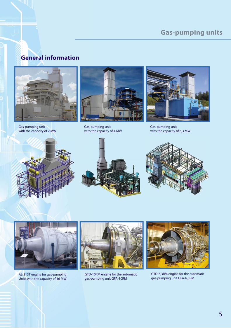
Gas-pumping units
General information
GTD-6,3RM engine for the automatic
gas-pumping unit GPA-6,3RMGTD-10RM engine for the automatic
gas-pumping unit GPA-10RMAL-31ST engine for gas-pumping
Units with the capacity of 16 MW
Gas-pumping unit
with the capacity of 2 MW
Gas-pumping unit
with the capacity of 4 MW
Gas-pumping unit
with the capacity of 6,3 MW

6
Standard engines used for gas-turbine units driving
Gas-turbine unit with the capacity of 13,7 MW
Unit technical data:
• Electric power, MW — 13,7;
• Turbine generator terminal voltage, kV — 6,3/13,8;
• Тhermal output, Gcal/h — 17,71;
• Performance coeffi cient, %:
− without heat recovery — 33,3;
− with heat recovery — 84,3.
• Hazardous emissions content in the exhaust gas of the GTE, mg/m3 — up to 50;
• Overhaul period, hour — 40 000;
• Specifi ed life, hour — 200 000;
• Integrated lubrication system for GTE and reduction gear, oil type — TP-22.
Gas-turbine units based on this engine are used in gas-turbine thermal power plants and
combined-cycle power installations building.
These units can operate in conventional cycle and also in combined (performance coeffi-
cient>50%) and cogeneration (performance coefficient >80%) cycles with combined power and
heat generation.
7
Standard engines used for gas-turbine units driving
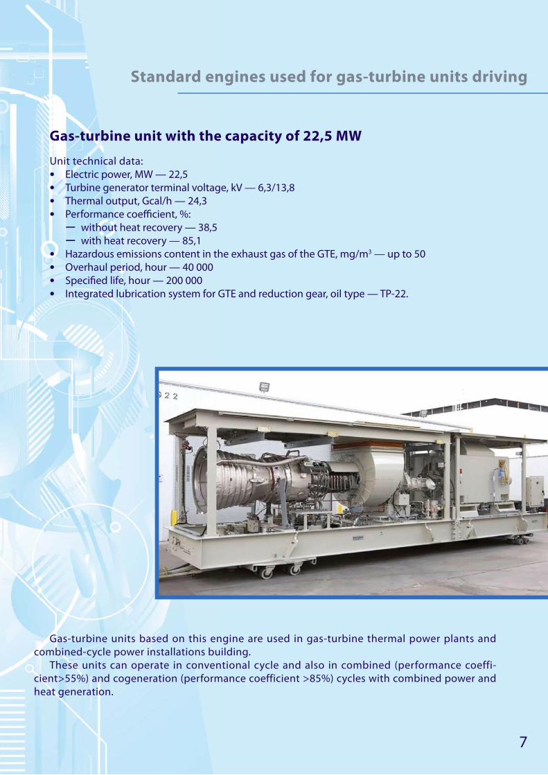
Gas-turbine unit with the capacity of 22,5 MW
Unit technical data:
• Electric power, MW — 22,5
• Turbine generator terminal voltage, kV — 6,3/13,8
• Тhermal output, Gcal/h — 24,3
• Performance coeffi cient, %:
− without heat recovery — 38,5
− with heat recovery — 85,1
• Hazardous emissions content in the exhaust gas of the GTE, mg/m3 — up to 50
• Overhaul period, hour — 40 000
• Specifi ed life, hour — 200 000
• Integrated lubrication system for GTE and reduction gear, oil type — TP-22.
Gas-turbine units based on this engine are used in gas-turbine thermal power plants and
combined-cycle power installations building.
These units can operate in conventional cycle and also in combined (performance coeffi-
cient>55%) and cogeneration (performance coefficient >85%) cycles with combined power and
heat generation.

8
Design and technical data
of a standard gas turbine engine
Gas-turbine engine with the capacity of 2,5 MW
Engine family for power plant generator driving with the capacity of 2,5 MW with the electric
frequency of:
Current frequency, Hz 50 60
Rotary speed, minute-1 12300+90 12300-90
Rotational speed of the output shaft, minute-1 1000 1000

9
Design and technical data
of a standard gas turbine engine
Technical data
Тype of engine Gas-turbine
Version General climate
Fuel type kerosene, dieselnatural or associated
gas
Lubricant type flood lubrication
Capacity of engine power settings with
generator load, kW:
- no-load conditions 0
- 0,5 of the rated power 1250
- rated power 2500
- overload 2750
Fuel consumption with rated power set-
ting up to , kg/h995 836
Specific fuel consumption with rated
power setting, up to , kg/kW/h0,398 0,334
Gas temperature behind the turbine,
up to, °С
- at the start-up 750
- at the rated power 520
Total dimensions, mm
- length 3500
- width 890
- height 1180
Operational conditions:
- air temperature at the inlet
of the engine, °Сfrom−50 up to +55
- relative humidity, up to, % 85
Delivery weight of the engine,
up to, kg1200

10
Engine assemblies’ configuration
Driving engine axial section
Driving engine physical configuration

11
Engine assemblies’ configuration
Reduction gear
Reduction gear situated at the front part of the engine is used
for rotary speed reduction and power transfer from gas turbine
for synchronous generator shaft rotation.
The reduction gear consists of: planetary assembly, station-
ary ring gear, output shaft and engine torque meter mechanism
mounted in reduction gear casing cast in magnesium alloy.
Engine rotary drive to the reduction gear mechanism is pro-
vided by the drive shaft spring.
Front casing
The front casing is used for the transmission between com-
pressor and engine reduction gear.
The flanges located at the outside face of the front casing are
attached to the engine main systems units and trunnions which
mount the engine to the engine bed of the plant.
The crank chamber contains units’ drive components, com-
pressor rotary table front support and the inlet guide vanes.
Compressor
A 10-stage axial subsonic compressor is intended for air suc-
tion, compression and feeding to the combustion chamber.
The compressor drum disc rotor consists of ten separate discs
which bear the rotating blades on their rims.
Discs, rear shaft and rotating blades of the compressor rotary
are made of high-quality stainless steel.
The compressor casing is a welded structure with a plug and
socket unit in the horizontal plane. The rear flange of the com-
pressor casing is attached to the combustion chamber mount.
Setting the operating speed of the compressor avoiding com-
pressor stalls and shifting it to the reduced speed is made by
bleeding of a part of the air into the atmosphere through special
valves.
Labyrinth seals between rotor and stator suppress non-pro-
ductive air leaks increasing the compressor’s efficiency.
Constant speed of the compressor rotor at different power set-
tings, moderate rotational velocity and special structural features
guarantee high reliability of the compressor.
12
Engine assemblies’ configuration
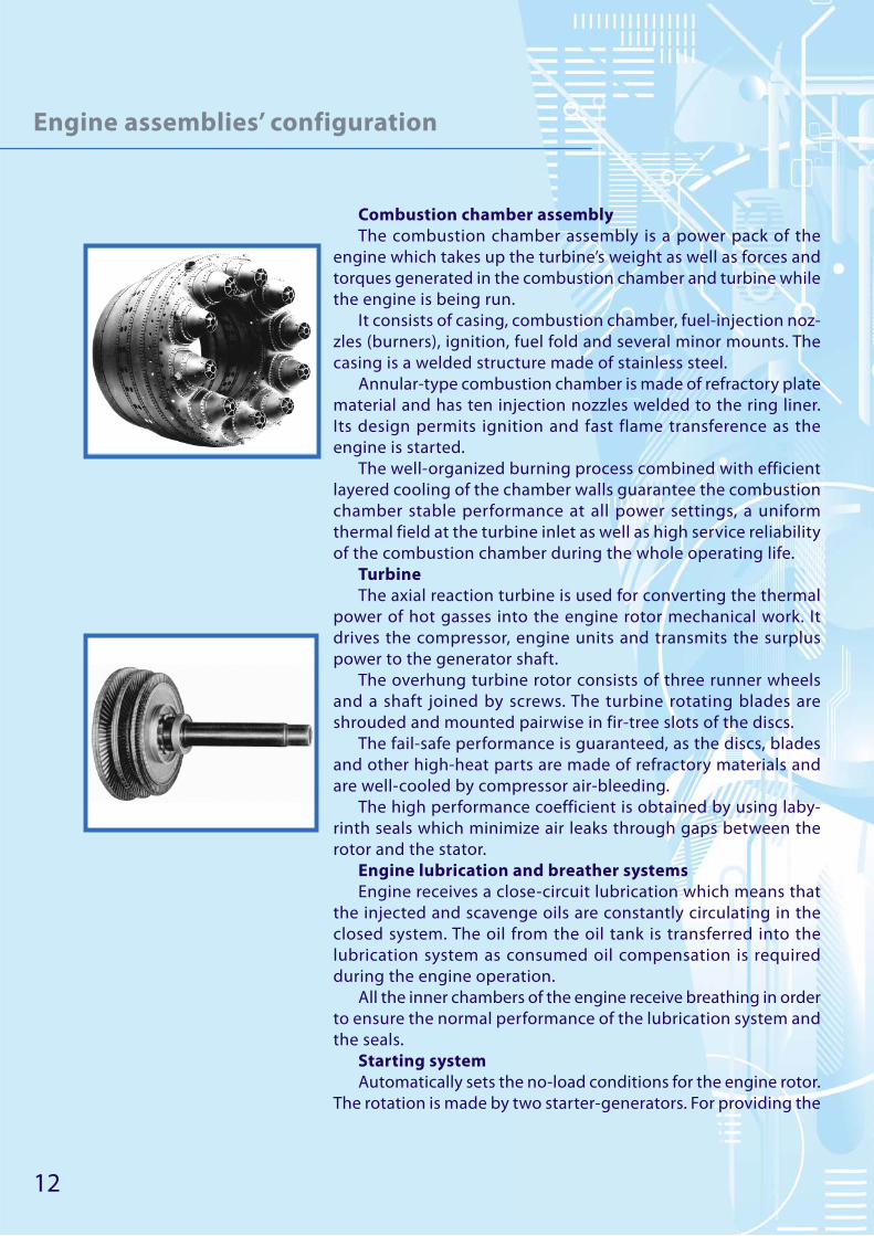
Combustion chamber assembly
The combustion chamber assembly is a power pack of the
engine which takes up the turbine’s weight as well as forces and
torques generated in the combustion chamber and turbine while
the engine is being run.
It consists of casing, combustion chamber, fuel-injection noz-
zles (burners), ignition, fuel fold and several minor mounts. The
casing is a welded structure made of stainless steel.
Annular-type combustion chamber is made of refractory plate
material and has ten injection nozzles welded to the ring liner.
Its design permits ignition and fast flame transference as the
engine is started.
The well-organized burning process combined with efficient
layered cooling of the chamber walls guarantee the combustion
chamber stable performance at all power settings, а uniform
thermal field at the turbine inlet as well as high service reliability
of the combustion chamber during the whole operating life.
Turbine
The axial reaction turbine is used for converting the thermal
power of hot gasses into the engine rotor mechanical work. It
drives the compressor, engine units and transmits the surplus
power to the generator shaft.
The overhung turbine rotor consists of three runner wheels
and a shaft joined by screws. The turbine rotating blades are
shrouded and mounted pairwise in fir-tree slots of the discs.
The fail-safe performance is guaranteed, as the discs, blades
and other high-heat parts are made of refractory materials and
are well-cooled by compressor air-bleeding.
The high performance coefficient is obtained by using laby-
rinth seals which minimize air leaks through gaps between the
rotor and the stator.
Engine lubrication and breather systems
Engine receives a close-circuit lubrication which means that
the injected and scavenge oils are constantly circulating in the
closed system. The oil from the oil tank is transferred into the
lubrication system as consumed oil compensation is required
during the engine operation.
All the inner chambers of the engine receive breathing in order
to ensure the normal performance of the lubrication system and
the seals.
Starting system
Automatically sets the no-load conditions for the engine rotor.
The rotation is made by two starter-generators. For providing the
13
Design of the engine blocks
reliable compressor performance at the start the air is bled into the atmosphere. Rotation speed
and the corresponding fuel flow are adjusted by the fuel-control unit.
Anti-icing system
A special unit signals when there is ice detected at the engine inlet. The electric mechanism
starts hot air feeding through the traction system in order to preheat the inlet guide vanes of the
compressor and other parts located at the engine inlet line.
The front casing fins cavities are being constantly preheated by the hot oil circulation.
Engine mounting to the power plant engine bed
Made by four trunnions: two are located on the front casing in horizontal plane, two are situ-
ated on the compressor and combustor joint flange at the horizontal axis angle of 7°.
Delivery package:
• a single set of spare parts;
• a set of engine operational documentation.
Maintenance:
• service maintenance by the manufacturer;
• low operational costs;
• low maintenance expenses;
• high operational reliability;
• mobility and promptness in fault repair;
• service in any place of the world;
• on-condition maintenance;
• the manufacturer assigns his experts for the period of the start-up and, if necessary, for any
operational period;
• theoretic and practical training of the Customer’s staff at the manufacturing plant or at the
operational site in any place of the world.
The Customer is provided with information which prevents from errors in the course of engine
operation. Our experts have decades of experience in technical support of engines..
Repaire service
• the repair service rendering is monitored by the manufacturer;
• the manufacturer guarantee the supply of necessary parts, assemblies and other products for
local repair during operation;
• the overhaul engine repair is performed by the manufacturer with the initial life recovery and
initial settings (main data) reset;
• the manufacturer is ready to cooperate with companies willing to organize their own mainte-
nance department.

14
Design and technical data
of a standard gas-turbine engine
Gas-turbine engine with the capacity of 10 МW
This is a modern gas-turbine engine for centrifugal air blower drive.
Scope of application:
For driving gas-pumping units centrifugal air blowers with the rated power of 10 МW.
Design criterion:
• low operational expenses;
• high productivity;
• easy maintenance and repair;
• high reliability;
• high environmental performance indicators.

15
Design and technical data
of a standard gas-turbine engine
Technical data of gas-turbine drive
Parameter Declared measure Conditions
Rated power, kW/h 10000
Fuel gas flow-rate, kg/h 2085 at Н= 11950 kkl/kg
Absolute thermal efficiency, % 34,5
Power turbine rotary speed, minute-1
АI-336-1-10 4800 – counter-clock-
wise
from exhaust outlet
АI-336-2-10 6500 – clockwise from exhaust outlet
Continuous work period
at the main power settings, min Unlimited
within operation life lim-
its with negative values
at sea level
Maximum capacity, kW/h 12000
Start System pneumatic,
turbine starter
Average number of starts in 1000
engine operational hours15
with 0°С, 760 mm Hg
content of О2=15%
Time for reaching the rated pow-
er minutes, up to10
Exhaust gas has a content:
− nitrogen oxides, mg/m3 50
− carbon, mg/m3 80
Sound pressure level, dB 145
Drive operating life:
till overhaul, h
rated, h, not less than
service life, years
25 000
100 000
12
Drive weight, kg, up to 5200
16
Design and technical data
of a standard gas-turbine engine
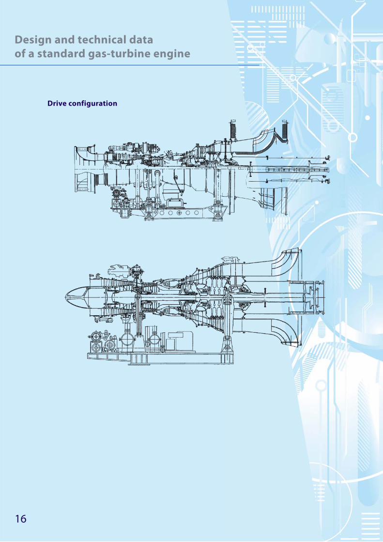
Drive configuration
17
Design and technical data
of a standard gas-turbine engine
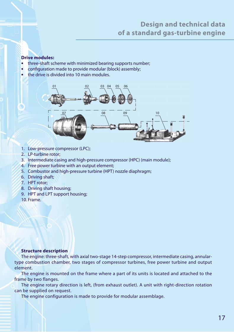
Drive modules:
• three-shaft scheme with minimized bearing supports number;
• confi guration made to provide modular (block) assembly;
• the drive is divided into 10 main modules.
01
07 08 09 10
02 03 04 05 06
1. Low-pressure compressor (LPC);
2. LP-turbine rotor;
3. Intermediate casing and high-pressure compressor (HPC) (main module);
4. Free power turbine with an output element;
5. Combustor and high-pressure turbine (HPT) nozzle diaphragm;
6. Driving shaft;
7. HPT rotor;
8. Driving shaft housing;
9. HPT and LPT support housing;
10. Frame.
Structure description
The engine: three-shaft, with axial two-stage 14-step compressor, intermediate casing, annular-
type combustion chamber, two stages of compressor turbines, free power turbine and output
element.
The engine is mounted on the frame where a part of its units is located and attached to the
frame by two flanges.
The engine rotary direction is left, (from exhaust outlet). A unit with right-direction rotation
can be supplied on request.
The engine configuration is made to provide for modular assemblage.
18
Design and technical data
of a standard gas-turbine engine
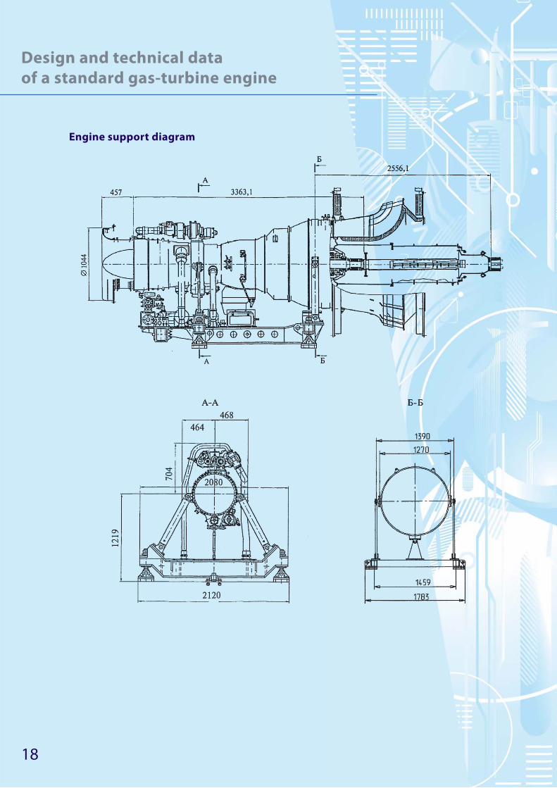
Engine support diagram

19
Design and technical data
of a standard gas-turbine engine
Electronic automation system
Electronic automation system (EAS):
• developed on the base of general purpose industrial building blocks;
• working conditions data are displayed on the PC screen;
• the engine’s EAS is integrated with GPU ACS at the standard traffi c channels level;
• has the structure of a stand-alone assembly mounted on the frame;
• improves GTE and GPU performance characteristics by means of engine monitoring and pro-
tection and by:
− increasing the accuracy of set-up parameters keeping with the help of effi cient control
algorithms implemented by the electronic controller;
− GTE and EAS monitoring which increases the failure-free operation period, improves engine
endurance, permits to perform on-condition maintenance;
− placing the units in the GPU and not on the engine in order to provide optimal thermal and
vibration conditions.
• can be run both in automatic mode by the GPU ACS and by operator.
The maintenance and repair service guarantees drives operation in any place of the world:
• service maintenance by the manufacturer;
• low operational costs;
• low maintenance expenses;
• high operational reliability;
• mobility and promptness in fault repair;
• service in any place of the world.
Our experts have decades of experience in technical support of engines.
Specific tasks:
• timely replacement of used assemblies and units;
• on-condition maintenance;
• theoretic and practical training of the Customer’s staff at the manufacturing plant or at the
operational site in any place of the world. The Customer is provided with information which
prevents from errors in the course of engine operation. The Customer is provided with informa-
tion which prevents from errors in the course of engine operation.

20
Design and technical data
of a standard gas-turbine engine
Engines used in industrial plants
Gas-turbine engine with the capacity of 8 МW
Gas-pumping unit based in the 8 МW engine

21
Design and technical data
of a standard gas-turbine engine
Driving engine axial section
1 2 3 4 5
789 6
1. LPC;
2. Intermediate casing;
3. HPT;
4. LP-turbine;
5. Power turbine;
6. HPC;
7. Combustion Chamber
8. Cone-shaped beam;
9. Power shaft train.
Main technical data of the driving engine:
• Rated power setting (Н=О, МСА):
− capacity, kW (hp) — 8000 (10720);
− absolute thermal effi ciency, % — 32,5.
• Off -peak conditions (Н = 0, МСА):
− capacity, kW (hp) — 3000 (4020).
• Exhaust gas temperature, К(°С) — 725 (452);
• Power turbine rotary speed, min-1 (s-1) — 8200 (136,67);
• Power turbine rated speed adjustment range — 0,70... 1,05;
• Weight, kg (/,) — 1470+30 (3240+65).
22
Design and technical data
of a standard gas-turbine engine
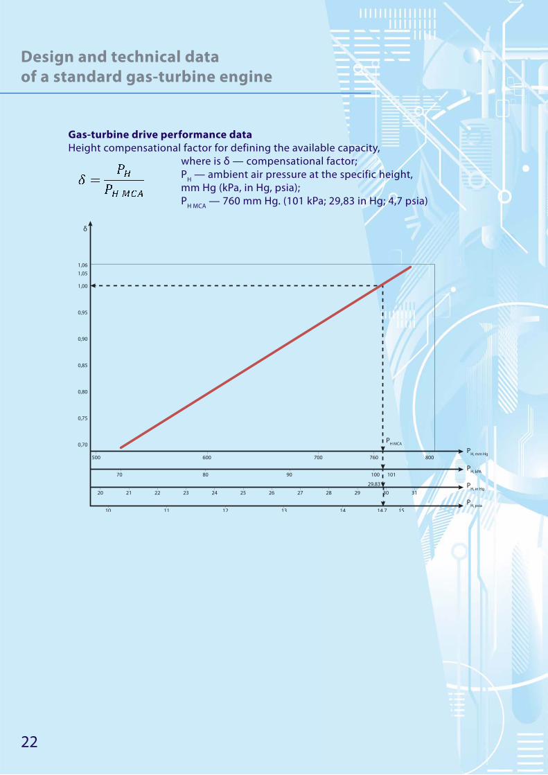
Gas-turbine drive performance data
Height compensational factor for defining the available capacity,
where is δ — compensational factor;
РН — ambient air pressure at the specific height,
mm Hg (kPa, in Hg, psia);
РН МСА
— 760 mm Hg. (101 kPa; 29,83 in Hg; 4,7 psia)
800600 700 760500
0,70
0,75
0,80
0,85
0,90
0,95
1,00
1,06
1,05
70
20
10 11 12 13 14 1514,7
29,83
21 22 23 24 25 26 27 28 29 30 31
80 90 100 101
δ
PH MCA
PH, mm Hg
PH, kPA
PH, psia
PH, in Hg
23
Design and technical data
of a standard gas-turbine engine
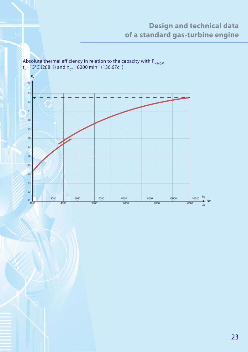
Absolute thermal efficiency in relation to the capacity with РН МСА
,
tH=15°C (288 K) and n
CT =8200 min-1 (136,67с-1)
3000
22
21
23
24
25
26
27
28
29
30
31
32
33
ηe
%
5000 6000 7000 8000 9000 10000 10720Ne
hp
kW4000 5000 6000 7000 8000
24
Design and technical data
of a standard gas-turbine engine
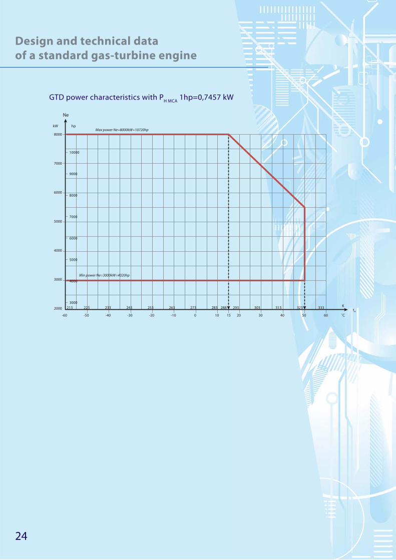
GTD power characteristics with РН МСА
1hp=0,7457 kW
8000
2000
-60
213
-50 -40 -30 -20 -10 0 10 15 20 30 40 50 60
3000
4000
5000
6000
7000
Ne
hp
tH
K
˚C
kW
10000
Max power Ne=8000kW=10720hp
Min power Ne=3000kW=4020hp
9000
8000
7000
6000
5000
4000
3000
223 233 243 253 263 273 283 293288 303 313 323 333

25
Design and technical data
of a standard gas-turbine engine
The design concept of a gas-turbine drive with the capacity of 8 МW
This drive is specially designed for mounting on gas-pumping, gas-lift and oil-pumping units.
Engineering was based on our long experience in designing, operation and development of
gas-turbine engines and electric power plants.
The drive is equipped with a newly designed automatic control system which includes the
following: GTD electronic controller, fuel gas feed controller, power turbine speed-limit device,
isolation valve, power-supply unit.
The engine meets the requirements for gas-turbine plants used in gas-pumping, gas-lift and
oil-pumping units.
The drive has two configuration variants as to the power turbine rotation direction and indus-
trial use:
Power turbine rotation Use Configaration
Counter-clockwise Oil-pumping and gas-lift units Variant 1
Clockwise Gas-pumping and gas-lift units Variant 2
Upon the request it is possible to produce unit variants with power turbine rotation speed of
5000 of 3000 (3600) min-1 (83,33 or 50(60) s-1).
As an option, the engines can be adapted for liquid fuel such as kerosene RT, TS-1 or equal
foreign-produced fuel.
The engine can be used for keeping the power of 6,3 МW (8442 hp) with the ambient air tem-
perature up to 312 К (+39 °С).
Drive short description
This is a three-shaft drive with an axial two-stage 13-step compressor (LPC and HPC), interme-
diate casing, annular-type combustion chamber, two compressor turbine stages (HPT and LPT),
two-staged power turbine and exhaust unit.
The АI-336-8 also includes: input device; attachment fittings and centering control on the bed
frame; starting, control, feeding, lubrication and breathing systems, settings control and condi-
tion testing.
Operation: the air coming through the GTD input device is compressed by low-pressure and
high-pressure compressors and is fed to the combustion chamber, where it is mixed with natural
gas coming through the nozzles and transforms into the fuel-air mixture. As the mixture burns,
the gas flow temperature is rising. Then the gas is fed to the turbine where the air flow energy is
converted into mechanical work used for driving the low-pressure and high-pressure compressors
and centrifugal blower.
In order to guarantee the reliability of the drive and enhance its durability we are working
through the possibility to develop LPC by assembling to it an additional so-called “zero” stage
which will increase the pressure of the two-staged compressor and the temperature of the gas at
the inlet of the turbine.

26
Design and technical data
of a standard gas-turbine engine
Modules of the drive
1
7 8 9
2 3 4 5 6
1. Low-pressure compressor;
2. Intermediate casing with the high-pressure compressor — the main module
3. Combustion chamber
4. High-pressure turbine rotor;
5. High-pressure and low-pressure turbines body frame;
6. Low-pressure turbine;
7. Power turbine;
8. Cone-shaped beam;
9. Power shaft train.

27
Design and technical data
of a standard gas-turbine engine
Main dimensions and drive anchor points
Retainer
Dimensions, mm (inches):
• length: 5379,5 (211,79);
• width: 1068,0 (42,05);
• height: 1227,4 (48,32)

28
Design and technical data
of a standard gas-turbine engine
Overall view and dimensions of gas-regulating system assembly
Reliability and durability index, warranty:
• No-failure operating time (time between failures), h — not less than 4000;
• Overhaul life (TBO), h — not less than 25000;
• Service life limit, h — not less than 100000;
• Drive overhaul life — 12 years, storageability time included.
The supplier guarantees that the unit meets the requirements of TOR if the consumer follows
the terms of operation, transportation and storage.
The warranty lifetime and storageability time is 7 years in warehouse from the acceptance data
including 4 years of storage at open platforms without shelter or 5 years — at a site with a shelter
in areas of moderate and cold climate. In regions with tropical climate the guaranteed storage-
ability period of the product in the supplier’s package is 2 years in sheltered warehouses.
The indicated warranty is valid for the supplied spare parts of a single package, board instru-
ments and component parts of the GTD.

29
Design and technical data
of a standard gas-turbine engine
Environmental performance
50 (24,3)
80 (64)
150 (73)
300 (240)
0
50
100
150
200
250
300
350
NOx CO
Hazardous emissions content (mg/nm3) in the exhaust gasses with the rated capacity (ppm).
Controllability
The high level of controllability provides an efficient and safe on-condition operation of the
drive.
Current monitoring is carried out using 15 status check parameters and 50 GTD status check
messages. The automatic control system helps to immediately obtain the data of condition and
parameter-trends of GTD and its systems as well as to forecast their technical condition basing
on the collected information.
The GTD configuration permits to perform periodic examination of the parts and assemblies of
the gas-air flow duct (rotating blades of all compressors’ and turbines’ stages, inner surface of the
combustion chamber) through special openings using an optical device in order to estimate its
technical condition. There are oil sampling points at the GTD designed for periodic oil tests for wear
products content detection and also swarf analyzer and three high-temperature swarf indicators.

30
Design and technical data
of a standard gas-turbine engine
Unit operation technical support
Engines and GTD operation technical support is performed by a developed network of Main-
tenance and repair department (MRD) experts. The MRD is the main link between the plant and
operating entities:
• has its representatives in more than 100 places in the world;
• assigns its experts to the operating entity as it supplies engines to be used in aircrafts, helicop-
ters or GTD;
• asseblies to be installed in ground industrial plants;
• provides comprehensive 24-hour/7-day cooperation with operating entities representatives.
MRD ensures:
• warranty and service maintenance of the engines and GTD in any region;
• mobility and promptness in fault repair;
• immediate and effi cient reaction to operating entities requests;
• collection and processing of the engine and GTD operation data for their further development;
• performing works in operating entities on order to enhance reliability and improve the perfor-
mance of engines and GTD;
• engines and GTD reconstruction under fi eld conditions by assemblies and modules replace-
ment;
• preparing and rendering services such as engineering;
• engines and GTD on-condition operation;
• qualifi ed consulting on all issues regarding engines and GTD operation;
• theoretic and practical training of the operating entities’s staff at the manufacturing plant or at
the operational site in any place of the world.

31
Gas-pumping units
General information
We supply over 50 modifications of gas-pumping units (GPU) for line and booster compressor
stations (BCS), underground gas storages (UGS), both for newly constructed and reconstructed
facilities. GPU are delivered as unified and functionally complete highly compatible assemblies
or as modules to be mounted at the operating site using common lifting facilities and tools. As to
their structure, GPU are made as easy-to-assemble panel hangars and as self-contained units. GPU
are also supplied as items for reconstruction (upgrade) of different types of units.
Gas-pumping unit consisting of
self-contained assemblies
with the capacity of 12 МW
Gas-pumping unit with the
capacity of 16 МW

32
Gas-pumping units
Main features of gas-pumping units:
• delivered as highly compatible assemblies to the mounting
site;
• use up-to-date Russian and foreign automatic control sys-
tems with modern Micro-PC element base manufactured by
SIEMENS (Germany);
• has air-cleaning equipment with cyclone and accumulative
• fi lters which ensure air cleaning according to the European
standard EN-779-94-F7-F9 with 99,7% effi ciency;
• using oil-free centrifugal compressors with magnetic rotor
suspension and dry gas seals;
• using NVH casing for gas-turbine engine which also provides
high level of fi re and explosion safety of the power drive
(assembly);
• using plate-fi n oil air coolers (OAC) with frequency regula-
tion of fans’ rotation speed;
• using axial fans in GTU cooling systems which are reliable
and have low noise level;
• can be furnished with a modular assembly of fuel gas treat-
ment;
• can be refi lled by portable oil fi lling unit;
• design and fabrication of GPU are performed according to
the quality control system which conforms with the interna-
tional ISO 9000 standards.
Gas-pumping unit at the Igrinskaya
compressor station
Gas-pumping unit at the Permskaya
compressor station

33
Gas-pumping units
Gas-pumping units for line compressor stations
Used for equipping the line compressor stations both operating and under construction which
transport natural gas by transfer pipelines.
As to their structure, GPU are made as easy-to-assemble panel hangars and as self-contained
units.
GPU are equipped with centrifugal compressors (CC) manufactured in Russia and abroad and
gas-turbine units (GTU) built basing on aircraft engines.
GPU are compatible with different drives which may be any of existing GTU and compressors
resulting in uniform units with capability ranging from 4 up to 25 МW depending on the existing
compressor stations.
Gas-pumping unit with the capacity
of 16 МW at the Smolenskaya
compressor station
Gas-pumping unit with the capacity
of 12 МW at the Krasnodarskaya
compressor station

34
Gas-pumping units
Main technical data
Parameter GPU-6,3 GPU-12 GPU-16 GPU-25
Rated power, MW 6,3 12 16 25
Commercial output,
mln. nm3/day
11,5 20,4...32,6 22,0...35,0 44,5...57,0
Compressor pressure, MPa 5,49 5,45...9,61 5,45...8,33 7,45
Compression ratio 1,44 1,32...1,7 1,44...1,61 1,37...1,5
Polytropic thermal efficiency
of the compressor
0,84 0,85-0,86 0,85-0,86 0,85-0,86
Power turbine rotation speed,
rpm
8200 6500 5300 5000
GTU absolute thermal efficiency
(station conditions)
0,30 0,34 0,363 0,395
GTU fuel gas specific flow rate,
kg/kW/h
0,239 0,208 0,192 0,177
Gas pressure (max), MPa:
- start
- fuel
0,294
0.49
0,6
3,0
0,6
3,2
0,6
4,5
Oil type:
- engine
- compressor
MS-8P
TP-22S
MS-8P
TP-22S
MS-8P
TP-22S
MS-8P
TP-22S
Weight, tons - 170 220 310
Total resource, thousand hours 100 100 100 100
GPU modification for line compressor stations
Modification Configuration
Power rating 6 MW
Variant 1 Self-contained units
Power rating 12 MW
Variant 1 Self-contained units
Variant 2 In hangar
Power rating 16 MW
Variant 1 Factory-assembled
Variant 2 In hangar
Power rating 25 MW
Variant 1 In hangar
35
Gas-pumping units
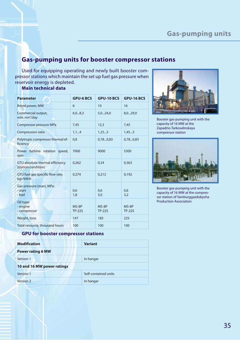
Gas-pumping units for booster compressor stations
Used for equipping operating and newly built booster com-
pressor stations which maintain the set up fuel gas pressure when
reservoir energy is depleted.
Main technical data
Parameter GPU-6 BCS GPU-10 BCS GPU-16 BCS
Rated power, MW 6 10 16
Commercial output,
mln. nm3/day
6,0...8,3 5,0...24,0 8,0...29,0
Compressor pressure MPa 7,45 12,3 7,45
Compression ratio 1,1...4 1,25...3 1,45...3
Polytropic compressor thermal ef-
ficiency
0,8 0,78...0,83 0,78...0,83
Power turbine rotation speed,
rpm
7000 9000 5300
GTU absolute thermal efficiency
(station condition)
0,262 0,34 0,363
GTU fuel gas specific flow rate,
kgг/kW•h
0,274 0,212 0,192
Gas pressure (max), МPa:
- start
- fuel
0,6
1,8
0,6
3,0
0,6
3,2
Oil type:
- engine
- compressor
MS-8P
TP-22S
MS-8P
TP-22S
MS-8P
TP-22S
Weight, tons 147 185 225
Total resource, thousand hours 100 100 100
GPU for booster compressor stations
Modification Variant
Power rating 6 MW
Version 1 In hangar
10 and 16 MW power ratings
Version 1 Self-contained units
Version 2 In hangar
Booster gas-pumping unit with the
capacity of 16 МW at the
Zapadno-Tarkosalinskaya
compressor station
Booster gas-pumping unit with the
capacity of 16 МW at the compres-
sor station of Yamburggazdobycha
Production Association

36
Gas-pumping units
Gas-pumping units for underground gas storages
Used for equipping operating and newly built underground
gas storages which collect and use natural gas reserves destined
to cover peak consumption.
Main technical data
Parameter GPU-4 UGS GPU-10 UGS
Rated power, MW 4 10
Commercial output,
mln. nm3/day
1,8...2,5 4,0...11,3
Compressor pressure MPa 9,92...14,4 7,45...14,4
Compression ratio 2,2...3 1,57...3,26
Polyptropic compressor thermal effi-
ciency
0,76...0,80 0,76...0,83
Power turbine rotation speed, rpm 14000 9000
GTU absolute thermal efficiency (station
conditions)
0,24 0,34
GTU fuel gas specific flow rate, kg/kW•h 0,303 0,212
Gas pressure (max), MPa:
- start
- fuel
0,6
1,5
0,6
3,0
Oil type:
- engine
- compressor
MS-8P
TP-22S
MS-8P
TP-22S
Weight, tons 98 185
Total resouce, thousand hours 100 100
GPU modification for underground gas storages:
Modification Variant
Power rating 4 MW
Variant 1 Self-contained units
Power rating 10 MW
Variant 1 Self-contained units
Gas-pumping unit for underground
gas storages with capacity of 10 MW
at the Karashurskaya compressor
station
Gas-pumping unit at the Permskaya
compressor station
37
Standard gas-turbine engines
used in turbine electric power plants
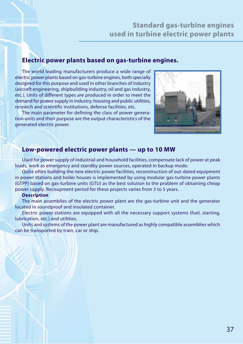
Electric power plants based on gas-turbine engines.
The world leading manufacturers produce a wide range of
electric power plants based on gas-turbine engines, both specially
designed for this purpose and used in other branches of industry
(aircraft engineering, shipbuilding industry, oil and gas industry,
etc.). Units of different types are produced in order to meet the
demand for power supply in industry, housing and public utilities,
research and scientific institutions, defense facilities, etc.
The main parameter for defining the class of power genera-
tion units and their purpose are the output characteristics of the
generated electric power.
Low-powered electric power plants — up to 10 МW
Used for power supply of industrial and household facilities, compensate lack of power at peak
loads, work as emergency and standby power sources, operated in backup mode.
Quite often building the new electric power facilities, reconstruction of out-dated equipment
in power stations and boiler houses is implemented by using modular gas-turbine power plants
(GTPP) based on gas-turbine units (GTU) as the best solution to the problem of obtaining cheap
power supply. Recoupment period for these projects varies from 3 to 5 years.
Description
The main assemblies of the electric power plant are the gas-turbine unit and the generator
located in soundproof and insulated container.
Electric power stations are equipped with all the necessary support systems (fuel, starting,
lubrication, etc.) and utilities.
Units and systems of the power plant are manufactured as highly compatible assemblies which
can be transported by train, car or ship.

38
Standard gas-turbine engines
used in turbine electric power plants
Standard technical specifications of a gas-turbine power plant with
the capacity of 2,5 МW
Rated terminal power of the generator, МW 2,55
Exhaust heat power with exhaust t.=110 °С, Gcal/h 5,82
Gas temperature behind the turbine (exhaust), °С 361
Gas flow behind the turbine (exhaust), kg/s 25,6
Equivalent operation sound level, not exceeding, dBA 80
Operating life, h:
- till overhaul
- specified
30 000
120 000
Fuel:
• natural gas (other type as agreed).
Advantages of GTPP:
• Do not require neither expensive facilities building nor large
groups of maintenance staff ;
• Highly compatible assemblies are supplied which reduces
the time for mounting, commissioning and start-up of the
facilities;
• All equipment fully complies with environmental require-
ments regarding emissions and noise.
• The equipment can operate both in parallel circuit and in
standalone mode, which increases signifi cantly the facilities’
energy safety level. It means that in case of emergency dis-
connection of the consumers from the supply network it can
automatically shift to the local load thus preventing nega-
tive eff ects of failures in the power network;
• Short period of recoupment of GTPP: from 3 to 5 years;
• Self-contained units;
• Reliability;
• Maintenance works are not time-consuming;
• High performance
The unit can be equipped with additional power modules in order to increase its capacity.
39
Standard gas-turbine engines used in
turbine electric power plants
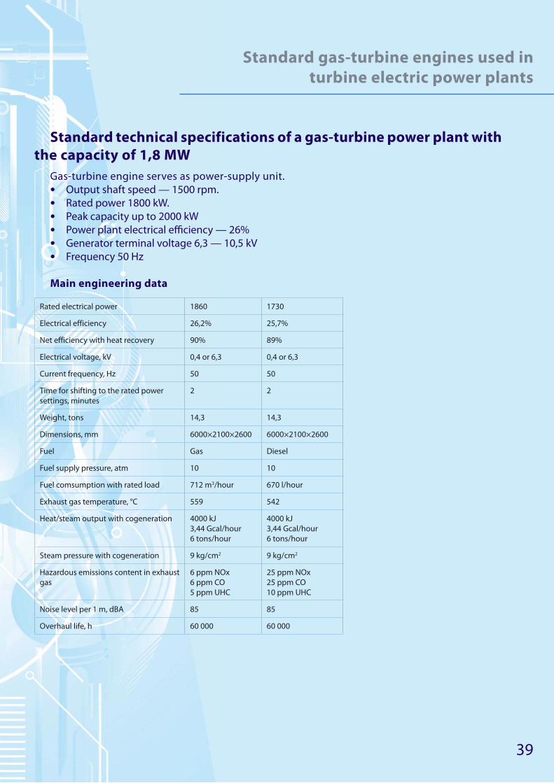
Standard technical specifications of a gas-turbine power plant with
the capacity of 1,8 МW
Gas-turbine engine serves as power-supply unit.
• Output shaft speed — 1500 rpm.
• Rated power 1800 kW.
• Peak capacity up to 2000 kW
• Power plant electrical effi ciency — 26%
• Generator terminal voltage 6,3 — 10,5 kV
• Frequency 50 Hz
Main engineering data
Rated electrical power 1860 1730
Electrical efficiency 26,2% 25,7%
Net efficiency with heat recovery 90% 89%
Electrical voltage, kV 0,4 or 6,3 0,4 or 6,3
Current frequency, Hz 50 50
Time for shifting to the rated power
settings, minutes
2 2
Weight, tons 14,3 14,3
Dimensions, mm 6000×2100×2600 6000×2100×2600
Fuel Gas Diesel
Fuel supply pressure, atm 10 10
Fuel comsumption with rated load 712 m3/hour 670 l/hour
Exhaust gas temperature, °С 559 542
Heat/steam output with cogeneration 4000 kJ
3,44 Gcal/hour
6 tons/hour
4000 kJ
3,44 Gcal/hour
6 tons/hour
Steam pressure with cogeneration 9 kg/cm2 9 kg/cm2
Hazardous emissions content in exhaust
gas
6 ppm NOx
6 ppm CO
5 ppm UHC
25 ppm NOx
25 ppm CO
10 ppm UHC
Noise level per 1 m, dBA 85 85
Overhaul life, h 60 000 60 000

40
Standard gas-turbine engines
used in turbine electric power plants
Standard layout of low-powered electric power plant by the example of a gas-turbine
unit manufactured in Europe

41
Standard gas-turbine engines
used in turbine electric power plants
High-capacity power plants from 10 up to 50 МW
Used for power and heat supply of single industrial and household facilities as well as of areas
and small populated localities:
• oil and gas fi elds infrastructure;
• metallurgical complexes;
• desalination plants;
• plants and factories;
• trade centres;
• hotels and restaurants;
• remote settlements and industrial facilities which lack centralized power supply, etc.
Gas-turbine units have two/three-way feed, and thermal power plants of different configura-
tion and purposes have fuel efficiency over 80%. Gas-turbine units are designed and engineered
so that the required maintenance is minimized reducing the expensive downtimes. Gas-turbine
units suppose low maintenance expenses and the possibility of fast mounting and start-up at the
Customer’s site. Their electrical efficiency reaches 35%. If the unit is combined with a steam turbine
this index increases up to 48%.
The ignition and start-up systems has a high efficiency and ensures start reliability of 99,5% in
different climate conditions.

42
Standard gas-turbine engines
used in turbine electric power plants
Standard technical data of a gas-turbine electric power plant by
the example of a unit with the capacity of 16 МW
The unit is equipped with a turbine with the rotational speed of 3000 rpm. By reducing the
rotational speed the turbine can be used as a generator drive without reduction gear, which helps
to increase gas-turbine unit reliability and cut total operational costs.
GTPP serve as main or standby power source, either autonomously or along with other power
supply units. It is possible to recover waste heat in recovery boiler which can be hot-water type
or steam boiler.
Description
Gas-turbine electric power plant is distinguished by:
• optimal engineering factors and endurance characteristics;
• minimum quantity of maintenance staff ;
• minimum production areas;
• minimum fuel consumption per 1 kW/h of the generated power among the competition in this
power class;
• minimized maintenance and repair costs which ensure the lowest possible power and heat
production costs.
Main technical data:
• Rated terminal power of the generator, МW — 16,3;
• Exhaust heat power with exhaust t =110 °С, Gcal/h — 19,48;
• Gas temperature behind the turbine (exhaust) — 481 °С;
• Gas fl ow behind the turbine (exhaust) — 56,26 kg/s;
• Equivalent operation sound level — not exceeding 80 dBA.
Fuel:
• natural gas;
• other type of fuel as agreed.
Advantages:
• Do not require neither expensive facilities building nor large groups of maintenance staff .
• Highly compatible assemblies are supplied which reduces the time for mounting, commission-
ing and start-up of the facilities.
• All equipment fully complies with environmental requirements regarding emissions and noise.
• The equipment can operate both in parallel circuit and in standalone mode, which increases
signifi cantly the facilities’ energy safety level. It means that in case of emergency disconnection
of the consumers from the supply network it can automatically shift to the local load thus pre-
venting negative eff ects of failures in the power network.
• Short recoupment period — 3–5 years.
• Reliability.
• Maintenance is not time-consuming.
• High effi ciency.
43
Standard gas-turbine engines
used in turbine electric power plants
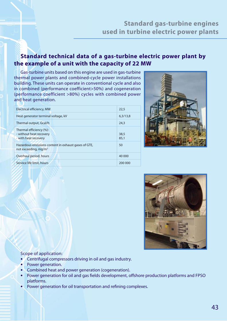
Standard technical data of a gas-turbine electric power plant by
the example of a unit with the capacity of 22 МW
Gas-turbine units based on this engine are used in gas-turbine
thermal power plants and combined-cycle power installations
building. These units can operate in conventional cycle and also
in combined (performance coefficient>50%) and cogeneration
(performance coefficient >80%) cycles with combined power
and heat generation.
Electrical efficiency, МW 22,5
Heat generator terminal voltage, kV 6,3/13,8
Thermal output, Gcal/h 24,3
Thermal efficiency (%):
- without heat recovery
- with heat recovery
38,5
85,1
Hazardous emissions content in exhaust gases of GTE,
not exceeding, mg/m3
50
Overhaul period, hours 40 000
Service life limit, hours 200 000
Scope of application:
• Centrifugal compressors driving in oil and gas industry.
• Power generation.
• Combined heat and power generation (cogeneration).
• Power generation for oil and gas fi elds development, off shore production platforms and FPSO
platforms.
• Power generation for oil transportation and refi ning complexes.
44
Standard gas-turbine engines
used in turbine electric power plants
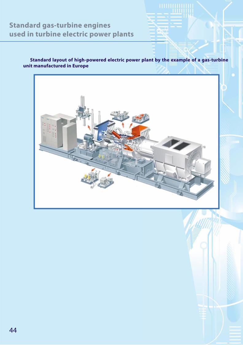
Standard layout of high-powered electric power plant by the example of a gas-turbine
unit manufactured in Europe
45
Standard gas-turbine engines
used in turbine electric power plants
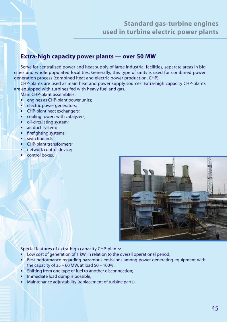
Extra-high capacity power plants — over 50 МW
Serve for centralized power and heat supply of large industrial facilities, separate areas in big
cities and whole populated localities. Generally, this type of units is used for combined power
generation process (combined heat and electric power production, CHP).
CHP-plants are used as main heat and power supply sources. Extra-high capacity CHP-plants
are equipped with turbines fed with heavy fuel and gas.
Main CHP-plant assemblies:
• engines as CHP-plant power units;
• electric power generators;
• CHP-plant heat exchangers;
• cooling towers with catalyzers;
• oil-circulating system;
• air duct system;
• fi refi ghting systems;
• switchboards;
• CHP-plant transformers;
• network control device;
• control boxes.
Special features of extra-high capacity CHP-plants:
• Low cost of generation of 1 kW, in relation to the overall operational period;
• Best performance regarding hazardous emissions among power generating equipment with
the capacity of 35 – 60 MW, at load 50 – 100%.
• Shifting from one type of fuel to another disconnection;
• Immediate load dump is possible;
• Maintenance adjustability (replacement of turbine parts).
46
Standard gas-turbine engines
used in turbine electric power plants
Standard technical data of a gas-turbine electric power plant with the capacity of 50 МW
• Fuel: natural gas, liquid fuel, dual-fuel system, using other types of fuel;
• Current frequency: 50 — 60 Hz;
• Electrical effi ciency — 37,5%;
• Thermal output — 9 597 kJ/kW/h;
• Turbine rotation speed — 6 608 rpm;
• Compressor pressure ratio — 19:1;
• Exhaust gas fl ow/temperature — 131,5 kg/sec, 544°С;
• NOx emissions (15% О2, dry emissions) — ≤15 ppm
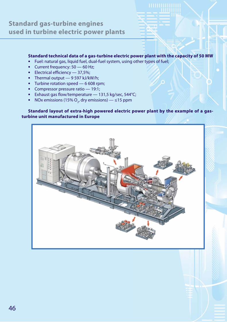
Standard layout of extra-high powered electric power plant by the example of a gas-
turbine unit manufactured in Europe
47
Standard gas-turbine engines
used in turbine electric power plants
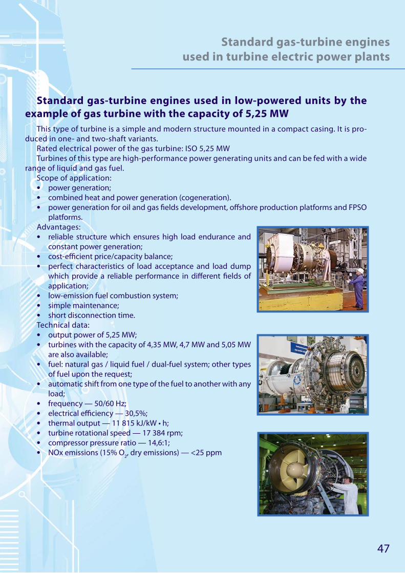
Standard gas-turbine engines used in low-powered units by the
example of gas turbine with the capacity of 5,25 МW
This type of turbine is a simple and modern structure mounted in a compact casing. It is pro-
duced in one- and two-shaft variants.
Rated electrical power of the gas turbine: ISO 5,25 МW
Turbines of this type are high-performance power generating units and can be fed with a wide
range of liquid and gas fuel.
Scope of application:
• power generation;
• combined heat and power generation (cogeneration).
• power generation for oil and gas fi elds development, off shore production platforms and FPSO
platforms.
Advantages:
• reliable structure which ensures high load endurance and
constant power generation;
• cost-effi cient price/capacity balance;
• perfect characteristics of load acceptance and load dump
which provide a reliable performance in diff erent fi elds of
application;
• low-emission fuel combustion system;
• simple maintenance;
• short disconnection time.
Technical data:
• output power of 5,25 МW;
• turbines with the capacity of 4,35 МW, 4,7 МW and 5,05 МW
are also available;
• fuel: natural gas / liquid fuel / dual-fuel system; other types
of fuel upon the request;
• automatic shift from one type of the fuel to another with any
load;
• frequency — 50/60 Hz;
• electrical effi ciency — 30,5%;
• thermal output — 11 815 kJ/kW • h;
• turbine rotational speed — 17 384 rpm;
• compressor pressure ratio — 14,6:1;
• NOx emissions (15% О2, dry emissions) — <25 ppm

48
Standard gas-turbine engines
used in turbine electric power plants
Standard gas-turbine engines used in high-powered units by the
example of gas turbine with the capacity of 24,77 MW
This is a vigorous gas turbine with a long life cycle which is
perfectly fit for operation in any ambient conditions. The gas
turbine is a compact two-shaft unit, its electrical efficiency is
34,2%. The turbine can consume a wide range of fuel: gaseous
and different types of liquid fuel.
Scope of application:
• Power generation.
• Combined heat and power generation (cogeneration).
• Power generation for oil and gas fi elds development, off -
shore production platforms and FPSO platforms.
• Power generation for oil transportation and refi ning com-
plexes.
Advantages:
• low-emission fuel combustion system;
• high thermal effi ciency;
• long working time;
• multipurpose application of the gas-turbine units;
• cycle and constant operation, as well as operating in peak-load conditions;
• maintenance or gas-turbine engine replacement directly at the operating site of the unit;
• wide range of fuel consumed, shift from one type of fuel to another is made without discon-
necting;
• load dump is possible;
• all the components are supplied by the manufacturer after previous tests.
Technical characteristics:
• output power — 24,77 МW;
• fuel: natural gas / liquid fuel / dual-fuel system; other types of fuel upon the request;
• frequency — 50/60 Hz;
• electrical effi ciency — 34,2 %;
• thermal output — 10522 kJ/kW • h;
• turbine rotational speed — 7700 rpm;
• compressor pressure ratio — 14,0:1;
• exhaust gas fl ow / temperature — 80,4 kg/sec, 543 °С;
• NOx emissions (15% О2, dry emissions) — ≤ 25 ppm.
49
Standard gas-turbine engines
used in turbine electric power plants
Standard gas-turbine engines used in extra-high powered units by
the example of gas turbine with the capacity of 50 МW
This is an extra-high powered gas turbine with a long life cycle which is perfectly fit for opera-
tion in any ambient conditions and has low maintenance expenses. Electrical output power of the
gas turbine is 50 МW. The turbine consumes a wide range of fuel. A large amount of generated
heat used for combined generation process permits to employ this turbine in different branches
of industry.
Scope of application:
• power generation;
• combined heat and power generation (cogeneration).
Advantages:
• low costs in relation to the complete operational period;
• the unit is manufactured according to international regulations, standards and rules;
• all the components are supplied by the manufacturer after previous tests;
• best performance regarding hazardous emissions among power generating equipment with
the capacity of 35-60 МW, with the load of 50-100%;
• high production effi ciency;
• one-shaft variant (with two segmental bearings), cold-end drive, third-generation emission
reduction system;
• shift from one type of fuel to another is made without disconnecting;
• immediate load dump is possible;
• maintenance adjustability (replacement of turbine parts);
• software for monitoring and remote control of the system operation (E-Service Applications).
Technical data:
• output power — 50 МW;
• fuel: natural gas / liquid fuel / dual-fuel system; other types of fuel upon the request;
• current frequency — 50/60 Hz;
• electrical effi ciency — 37,5%;
• thermal output — 9 597 kJ/kW•h;
• turbine rotational speed — 6 608 rpm;
• compressor pressure ratio — 19:1;
• exhaust gas fl ow / temperature — 131,5 kg/sec, 544°С;
• NOx emissions (15% О2, dry emissions) — ≤15 ppm.

50
Services
Services rendered by Veya Investments Limited:
1. Development, engineering, gas-pumping units and compressor stations selection according
to the Customer’s requirements, engineering consulting.
2. All kinds of engineering and design services including energy audit, designer supervision and
project feasibility study.
3. Equipment delivery and OEM parts supply within the warranty and post-guarantee periods.
4. Ensuring reliability, safety and conformity with the required performance characteristics.
5. Installation supervision, commissioning and start-up, facility handover to the Customer on a
turnkey basis.
6. Customer’s equipment upgrade. Reliability and performance improvement. Maintenance
costs reduction. Power generation projects development and fi nancing assistance.
7. Overall equipment diagnostics. Mechanical section optimization and equipment power set-
tings improvement.
8. Customer’s staff training, skill development, periodic training which takes place either at the
manufacturing plant or at the Customer’s site.
9. The supplied equipment working state monitoring during the post-guarantee period, work-
ing out the recommendations on repair and maintenance upon the demand of the Customer.
Overall planning and total overhaul term defi ning.
10. Permanent structures and temporary assembly shelters for machinery building, generation
facilities construction on a turnkey basis.