Embed Size (px)
Citation preview
BURNDYSubstation
COPPER SUBSTATIONIntroduction .............................G-3
Type NTTube to Tube ............................G-4
Type NSNT/NHNTTube to Cable ..........................G-5
Type NSNT/NHNTCable to Cable ........................G-6
Type VTCable to Cable .......................G-7
Type NSTube to Tube.............................G-7
Type XPTube to Tube.............................G-8
Type BFlexible Braid Jumper ...G-8 - G-11
Type B Assembly ComponentsExpansion Coupler ................G-12
Type HFBWBar Clamp ..............................G-13
Type HFB-P1Bar Clamp ..............................G-14
Type HFB-NTap Pad Adapter.....................G-15
Type NATube to Flat ............................G-16
Type XATube to Flat, Expandable .......G-16
Type NAS/NAHCable to Flat (Terminal)..........G-17
Type N2AHTwo Cables to Flat..................G-18
Type VA, VVACable to Flat (Terminal)..........G-19
Type UHBus Support, Tube..................G-20
G-1
TABLE OF CONTENTS

BURNDYSubstation
G-2
Type UHRBus Support, Tube or Cable ...G-20
Type LH, LHRBus Support, Tube or Cable ...G-21
Type NDRStud Connector, Cable, Tube, Flat Bar .........................G-22
Type FDStud Connector, Stud to Flat Bar ...................................G-23
Type QGFLBar Tap, Cable to Flat .............G-24
Type FCBTransformer Tap Adapter ........G-24
Type E-C-GTransformer Tap Adapter ........G-25
Type FN .................................G-25
ALUMINUM SUBSTATIONIntroduction .............................G-26
Type NNT-ATube to Tube ...........................G-27
Type NNTR-ATube to Cable, Cable to Cable.. .........................G-27 - G-28
Type NS-ATube to Tube ...........................G-28
Type NA-ATube to Flat.............................G-29
Type XA-ATube to Flat.............................G-29
Type NBC-ATube to Flat .................G-30 - G-31
Type NAR-ACable to Flat ...........................G-32
Type UHG-ABus Support, Tube ..................G-33
Type UHKR-ABus Support, Tube or Cable ...G-33
Type LB-AEnd Cap, Aluminum Tube .......G-34
Type WAS-ATerminal Connector ................G-35
Type WASC-A-NCenterformed Terminal ...........G-36
Type WGAWeldment Ground Stud ..........G-37
TABLE OF CONTENTS (Continued)

BURNDYSubstation
COPPER SUBSTATION CONNECTORS
INTRODUCTION
BURNDY® electrical connectors are designedto be installed with a minimum of effort, to runcooler than the conductors being joined andto provide optimum performance under alloperating conditions.
To achieve this type of performance, exten-sive research and development time is spentby BURNDY® engineers and scientists toimprove manufacturing techniques, materialsand designs. As these improvements becomeavailable, they are incorporated into bothexisting and new product lines. This continu-ous program of product innovation andimprovement insures that, as new and morecritical applications evolve, high quality con-nectors from BURNDY® will be available to meet the need.
Flat pad connectors used to join cable or tubing terminals to equipment studs.
A variety of bus supports are also availablefor tube or cable. Some can be adjusted foreither a rigid or slide-fit by rotating the clamp-ing cap 180°.
Expansion connectors are used to absorb thestress imposed on the bus by settling ground,thermal expansion and shocks, as in circuitbreaker operations. The flexible elements areflat-tinned, copper braid, with sufficient crosssectional area to carry the rated current of theconductors being joined.
G-3
N-Line connectors are two-piece copper alloycastings assembled with DURIUM™ (siliconbronze) hex bolts, nuts and washers. Theyare available for connecting tube or cable.
The Variline incorporates a modified V-bolt asthe clamping element for heavy-duty applica-tions. This line is particularly suited for usewith flexible and extra flexible cables.

BURNDYSubstation
TYPE NT
T-CONNECTOR
FOR COPPER TUBE TO TUBE
High copper alloy T-Connector for tubing runand tap. Slots between bolts provide indepen-dent high-pressure areas of contact.One-wrench installation.
G-4
CATALOGNUMBER
CONDUCTORB H J LRUN ’A’ TAP ’AA’
NT1313 1/2 1/2
2
1-3/4
3/8
4
NT1413 3/4 1/22 4-1/8
NT1414 3/4 3/4
NT1514 1 3/42-1/8
4-3/8
NT1515 1 1 4-1/2
NT16141-1/4
3/42-1/2 4-3/4
NT1615 1
NT1616 1-1/4 2-3/4 2-5/8 1/2 5-3/4
NT17141-1/2
3/42
2-3/43/8 5-1/8
NT1715 1
NT1717 1-1/22-3/4
1/2
6-1/8
NT1816 2 1-1/43-1/4 6-5/8
NT1817 2 1-1/2
NT1818 2 2 3-1/8 3-3/8 6-3/4
NT1919 2-1/2 2-1/2 3-5/8 3-7/8 7-1/4
NT2020 3 3 4-3/8 4-5/85/8
8-5/8
NT2121 3-1/2 3-1/2 4-7/8 5-1/4 9-1/4
NT2222 4 4 5-1/2 5-3/4 9-7/8

BURNDYSubstation
TYPE NSNT/NHNT
T-CONNECTOR
FOR COPPER TUBETO CABLE
High copper alloy T-Connector for joining cop-per tubing run to a wide range of copper tapcable. Tap utilizes reversible cap to achievelarge conductor range and the connector isdesigned for one-wrench installation.
G-5
① Complete cable range may be accommodated by reversingcap.
GOLATACREBMUN
NURSPIRO
ASPHE
EGNARELBACREPPOCCOMMERCIAL
B B-B H"J".AID
L W YE➀TELPMOCELBACPATAAEGNAR
LLAMSPAT
EVOORG
EGRALPAT
EVOORG
9231TNSN).AID048.("2/1
OT)AID261.(.LOS6)AID575.(limck052
OT)AID261.(.LOS6)AID273.(.RTS0/1
OT)AID024.(.RTS0/2)AID575.(limck052
00.2 83.2 00.2 61-"8/3 80.5 69.1 98.3
9231TNSN 52.2 26.2 23.2 31-"2/1 28.5 44.2 83.4
9241TNSN
).AID050.1("4/3
OT)AID261.(.LOS6)AID575.(limck052
OT)AID261.(.LOS6)AID273.(.RTS0/1
OT)AID024.(.RTS0/2)AID575.(limck052
00.2 83.2 00.2 61-"8/3 80.5 69.1 98.3
9241TNHN 52.2 26.2 23.2 31-"2/1 28.5 44.2 83.4
4341TNSN OT)AID523.(.LOS0/1)AID318.(limck005
OT)AID523.(.LOS0/1)AID925.(.RTS0/4
OT)AID575.(limck052)AID318.(limck005
00.2 83.2 01.2 61-"8/3 80.5 02.2 98.3
4341TNHN 52.2 26.2 24.2 31-"2/1 28.5 65.2 83.4
9251TNSN
).AID513.1("1
OT)AID261.(.LOS6)AID575.(limck052
OT)AID261.(.LOS6)AID273.(RTS0/1
OT)AID024.(.RTS0/2)AID575.(limck052
00.2 83.2 00.2 61-"8/3 43.5 69.1 20.4
9251TNHN
52.2 26.2
75.2
31-"2/1
29.5
44.2
34.44351TNHN
OT)AID523.(.LOS0/1)AID318.(limck005
OT)AID523.(LOS0/1)AID925.(.RTS0/4
OT)AID575.(limck052)AID318.(limck005
75.2 65.2
0451TNHNOT)AID024.(.RTS0/2)AID130.1(limck008
OT)AID024.(.RTS0/2)AID318.(limck005
OT)AID318.(limck005)AID30.1(limck008
06.2 – 87.2
9261TNSN
).AID066.1("4/1-1
OT)AID261.(.LOS6)AID575.(limck052
OT)AID261.(.LOS6)AID273.(.RTS0/1
OT)AID024.(.RTS0/2)AID575.(limck052
00.2 83.2 73.2 61-"8/3 87.5 69.1 42.4
9261TNHN
96.2
26.2
75.2
31-"2/1
23.6
44.2
36.44361TNHN
OT)AID523.(.LOS0/1)AID318.(limck005
OT)AID523.(.LOS0/1)AID925.(.RTS0/4
OT)AID575.(limck052)AID318.(limck005
06.2 65.2
0461TNHNOT)AID024.(.RTS0/2)AID130.1(limck008
OT)AID024.(.RTS0/2)AID318.(limck005
OT)AID318.(limck005)AID130.1(limck008
86.2 87.2
4461TNHNOT)AID925.(.RTS0/4)AID251.1(limck0001
OT)AID925.(.RTS0/4)AID899.(limck057
OT)AID899.(limck057)AID251.1(limck0001
88.2 96.2 85.6 09.2 98.4
9271TNHN
).AID009.1("2/1-1
OT)AID261.(.LOS6)AID575.(limck052
OT)AID261.(.LOS6)AID273.(.RTS0/1
OT)AID024.(.RTS012)AID575.(limck052
96.2
26.2
07.2
67.6
44.2
58.44371TNHNOT)AID523.(.LOS0/1)AID318.(limck005
OT)AID523.(.LOS0/1)AID925.(.RTS0/4
OT)AID575.(limck052)AID318.(limck005
07.2 65.2
0471TNHNOT)AID024.(.RTS0/2)AID130.1(limck008
OT)AID024.(.RTS0/2)AID318.(limck005
OT)AID318.(limck005)AID130.1(limck008
87.2 87.2
4471TNHNOT)AID925.(.RTS0/4)AID251.1(limck0001
OT)AID925.(.RTS0/4)AID899.(limck057
OT)AID899.(limck057)AID251.1(limck0001
88.2 08.2 20.7 09.2 11.5
9281TNHN
).AID573.2("2
OT)AID261.(.LOS6)AID575.(limck052
OT)AID261.(.LOS6)AID273.(.RTS0/1
OT)AID024.(.RTS0/2)AID575.(limck052
96.2
26.2 60.3 44.7
44.2
91.54381TNHNOT)AID523.(.LOS0/1)AID318.(limck005
OT)AID523.(.LOS0/1)AID925.(.RTS0/4
OT)AID575.(limck052)AID318.(limck005
65.2
0481TNHNOT)AID024.(.RTS0/2)AID130.1(limck008
OT)AID024.(.RTS0/2)AID318.(limck005
OT)AID318.(limck005)AID130.1(limck008
87.2
4481TNHNOT)AID925.(.RTS0/4)AID251.1(limck0001
OT)AID925.(.RTS0/4)AID899.(limck057
OT)AID899.(limck057)AID251.1(limck0001
88.2 60.3 07.7 09.2 54.5
6481TNHNOT)AID251.1(limck0001
)AID214.1(limck0051–
OT)AID251.1(limck0001)AID214.1(limck0051
60.3 32.3 88.7 61.3 36.5
9291TNHN
).AID578.2("2/1-2
OT)AID261.(.LOS6)AID575.(limck052
OT)AID261.(.LOS6)AID273.(.RTS0/1
OT)AID024.(.RTS0/2)AID575.(limck052
96.2
26.2
46.3
60.8
44.2
05.54391TNHNOT)AID523.(.LOS0/1)AID318.(limck005
OT)AID523.(.LOS0/1)AID925.(.RTS0/4
OT)AID575.(limck052)AID318.(limck005
65.2
0491TNHNOT)AID024.(.RTS0/2)AID130.1(limck008
OT)AID024.(.RTS0/2)AID318.(limck005
OT)AID318.(limck005)AID130.1(limck008
87.2
4491TNHNOT)AID925.(.RTS0/4)AID251.1(limck0001
OT)AID925.(.RTS0/4)AID899.(limck057
OT)AID899.(limck057)AID251.1(limck0001
88.2 23.8 09.2 67.5
6491TNHNOT)AID251.1(limck0001
)AID214.1(limck0051–
OT)AID251.1(limck0001)AID214.1(limck0051
60.3 05.8 61.3 49.5
4402TNHN ).AID005.3("2/1-3OT)AID925.(RTS0/4)AID251.1(limck0001
OT)AID925.(.RTS0/4)AID899.(limck057
OT)AID899.(limck057)AID251.1(limck0001
57.5 62.4 59.8 09.2 70.6

BURNDYSubstation
TYPE NSNT/NHNT
T-CONNECTOR
FOR COPPER CABLE TO CABLE
High copper alloy reversible T-Connector forjoining a wide range of run and tap cables.Connector is designed for one-wrench instal-lation. “S” standard 3/8" hardware and “H” heavy duty 1/2 " hardware.
G-6
CATALOGNUMBER
COMMERCIAL COPPER CABLE RANGECOMPLETE RUN CABLE
RANGE A
COMPLETE TAP CABLE
RANGE AA
SMALLRUN
GROOVE
LARGERUN
GROOVE
SMALLTAP
GROOVE
LARGETAP
GROOVE
NSNT29296 SOL. (.162 DIA)
TO 250 kcmil (.575 DIA)
6 SOL. (.162 DIA) TO 1/0 STR.
(.372 DIA)
2/0 STR. (.420 DIA) TO 250 kcmil
(.575 DIA)
NHNT2929NSNT3429NHNT3429NSNT3434 1/0 SOL. (.325 DIA)
TO 500 kcmil (.813 DIA)
1/0 SOL. (.325 DIA)TO 4/0 STR.(.529 DIA)
250 kcmil (.575 DIA)TO 500 kcmil
(.813 DIA)NHNT3434
NHNT44296 SOL. (.162 DIA)
TO 250 kcmil (.575 DIA)
6 SOL. (.162 DIA)TO 1/0 STR.(.372 DIA)
2/0 STR. (.420 DIA)TO 250 kcmil
(.575 DIA)
NHNT44341/0 SOL. (.325 DIA)
TO 500 kcmil (.813 DIA)
1/0 SOL. (.325 DIA)TO 4/0 STR.(.529 DIA)
250 kcmil (.575 DIA)TO 500 kcmil
(.813 DIA)
NHNT44402/0 STR. (.420 DIA)
TO 800 kcmil (1.031 DIA)
2/0 STR. (.420 DIA)TO 500 kcmil
(.813 DIA)
500 kcmil (.813 DIA)TO 800 kcmil(1.031 DIA)
NHNT44444/0 STR. (.529 DIA)
TO 1000 kcmil (1.152 DIA)
4/0 STR. (.529 DIA)TO 750 kcmil
(.998 DIA)
750 kcmil (.998 DIA)TO 1000 kcmil
(1.152 DIA)
NHNT48341/0 SOL. (.325 DIA)
TO 500 kcmil (.813 DIA)
1/0 SOL. (.325 DIA)TO 4/0 STR.
(.529 DIA)
250 kcmil (.575 DIA)TO 500 kcmil
(.813 DIA)
NHNT48402/0 STR. (.420 DIA)
TO 800 kcmil (1.031 DIA)
2/0 STR. (.420 DIA)TO 500 kcmil
(.813 DIA)
500 kcmil (.813 DIA)TO 800 kcmil (1.031 DIA)
NHNT48444/0 STR. (.529 DIA)
TO 1000 kcmil (1.152 DIA)
4/0 STR. (.529 DIA)TO 750 kcmil
(.998 DIA)
750 kcmil (.998 DIA)TO 1000 kcmil
(1.152 DIA)
NHNT4846 —
NHNT4848
CATALOGNUMBER B B-B H "J" DIA. L W Y
NSNT2929 2.38 2.38 1.75 3/8"-16 4.60 1.96 3.62NHNT2929 2.62 2.62 2.07 1/2"-13 5.32 2.44 4.10NSNT3429 2.38 2.38 2.00 3/8"-16 4.84 1.96 3.74NHNT3429 2.62 2.62 2.32 1/2"-13 5.44 2.44 4.16NSNT3434 2.38 2.38 2.00 3/8"-16 4.84 2.20 3.74NHNT3434 2.62 2.62 2.32
1/2"-13
5.38 2.56 4.10NHNT4429
2.882.62
2.575.78
2.444.33NHNT4434 2.56
NHNT4440 2.78NHNT4444 2.88 6.03 2.90 4.58NHNT4834
3.25
2.62
3.07
6.262.56
4.57NHNT4840 2.78NHNT4844 2.88 6.51 2.90 4.82NHNT4846 3.06 6.76 3.16 5.07NHNT4848 3.25 6.94 3.38 5.25
6 SOL. (.162 DIA) TO 250 kcmil
(.575 DIA)
6 SOL. (.162 DIA) TO 1/0 STR.
(.372 DIA)
2/0 STR. (.420 DIA) TO 250 kcmil
(.575 DIA)
1000 kcmil (1.152 DIA) TO 1500 kcmil
(1.412 DIA)
1000 kcmil (1.152 DIA) TO 1500 kcmil
(1.412 DIA)500 kcmil (.813 DIA)
TO 2000 kcmil(1.632 DIA)
1500 kcmil (1.412 DIA) TO 2000 kcmil
(1.632 DIA)
500 kcmil (.813 DIA) TO 1500 kcmil
(1.412 DIA)
1/0 SOL. (.325 DIA)
TO 500 kcmil(.813 DIA)
1/0 SOL. (.325 DIA)
TO 4/0 STR.(.529 DIA)
250 kcmil (.575 DIA)
TO 500 kcmil(.813 DIA)
4/0 STR.(.529 DIA)
TO 1000 kcmil(1.152 DIA)
4/0 STR.(.529 DIA)
TO 750 kcmil(.998 DIA)
750 kcmil (.998 DIA)
TO 1000 kcmil(1.152 DIA)
500 kcmil (.813 DIA)
TO 2000 kcmil(1.632 DIA)
500 kcmil (.813 DIA)
TO 1500 kcmil(1.412 DIA)
1500 kcmil (1.412 DIA)
TO 2000 kcmil(1.632 DIA)
➀ Complete cable range may be accommodated by reversing cap.
➀ ➀
BURNDYSubstation
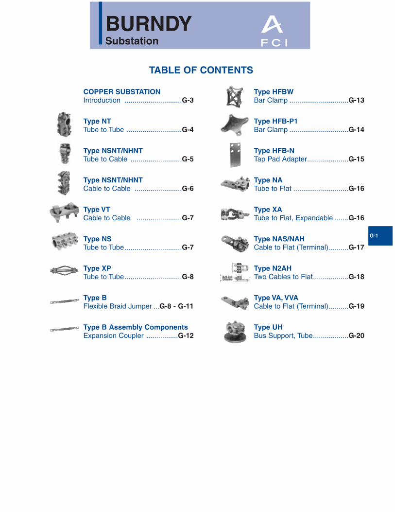
TYPE VT
T-CONNECTOR
FOR COPPER CABLE TO CABLE
High copper alloy T-Connector for cable run,cable tap, V-bolt clamping elements accom-modate large range of cable and are particu-larly suited for extra flexible cable. One-wrench installation.
TYPE NS
COUPLER
FOR COPPER TUBE TO TUBE
High copper alloy coupler for joining equalsizes of tube end to end. Slots between boltsprovide independent high pressure areas ofcontact. One-wrench installation.
G-7
CatalogNumber
Conductor - A Conductor - B J LFig.No.
NS1313 1/2 1/23/8
3-1/41
NS1414HC 3/4 3/4 4
NS1515 1 1 4-1/4
2
NS1616HC 1-1/4 1-1/4
1/2 5-3/4NS1717 1-1/2 1-1/2
NS1818 2 2
NS1919 2-1/2 2-1/2
NS2020 3 35/8
7-1/4
NS2121 3-1/2 3-1/2 8
NS2222 4 4 8-1/2
CatalogNumber
ConductorH L W
Run - A Tap - AAVT2C2C 8 Sol. - 2 Str. 8 Sol. - 2 Str. 1-3/8 2-3/8 1
VT2525 6 Sol. - 1/0 Str. 6 Sol. - 1/0 Str.1-5/8
2-5/81-1/4
VT2825 1/0 Str. - 4/0 Str. 6 Sol. - 1/0 Str.3-1/8
VT2828 1/0 Str. - 4/0 Str. 1/0 Str. - 4/0 Str. 1-3/4
VT3025 1/0 Str. - 300 6 Sol. - 1/0 Str.1-7/8 3-3/8
1-1/8
VT3030 1/0 Str. - 300 1/0 Str. - 300 2
VT3425 300-500 6 Sol. - 1/0 Str.
2-3/8
3-3/4 1-1/4
VT3428 300-500 1/0 Str. - 4/0 Str. 3-1/2 1-3/4
VT3430 300-500 1/0 Str. - 300 3-5/8 2
VT3434 300-500 300-500 3-3/4 2-1/4
VT4040 500-800 500-800 2-5/8 4-1/2 2-5/8
VT4425 750-1000 6 Sol. - 1/0 Str.2-7/8
4-3/8 1-1/4
VT4428 750-1000 1/0 Str. - 4/0 Str. 4-1/8 1-3/4
VT4834 1500-2000 300-5004-1/4
5-1/4 2-1/4
VT4844 1500-2000 750-1000 5-3/4 2-7/8
Fig. 1
Fig. 2

BURNDYSubstation
TYPE XP
EXPANSION COUPLER
FOR COPPER TUBE TO TUBE
High alloy copper expansion coupler for join-ing equal size tube on end. Extra flexibletinned copper braid allows longitudinal move-ment of the tube. Type XP has alignmentguide. One-wrench installation.
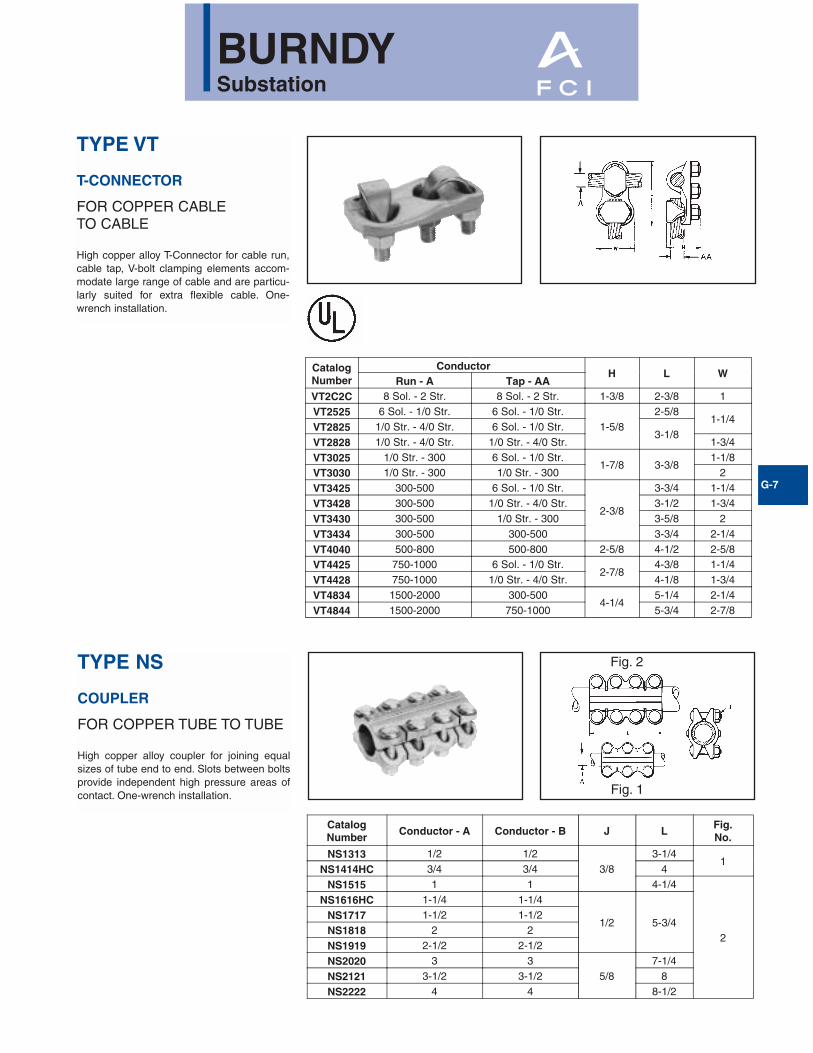
TYPE B
FLEXIBLE COPPER BRAID JUMPER
Flexible copper braid jumpers designed totake up linear expansion and contraction,compensate for misalignment and absorbvibratory movement of electrical equipmentand devices.
Made of flat, extra flexible, tinned, purecopper braid, with unplated, seamless, purecopper ferrules formed into a rectangularshape on each end.
Last two numbers in catalog number indicatetotal length of braid in inches, e.g., BD12N orBD12 is standard 12" long braid jumper. Allbraids are available in 12", 18", and 24"lengths.
Other lengths, plating and drilling are avail-able. Refer to factory.
G-8
Catalog Number
Conductor H J LStandard IPS
WithGuide
XP1313 1/2 3-7/83/8
8-3/4XP1414 3/4 4-1/8
XP1515 1 4-3/8 9-1/2
XP1616 1-1/4 5-7/8
1/2
11-1/2
XP1717 1-1/2 6-1/212
XP1818 2 7
XP1919 2-1/2 8-1/2 13
XP2020 3 7-3/45/8
13-1/2
XP2121 3-1/2 813-5/8
XP2222 4 9-1/8

BURNDYSubstation
FLEXIBLE COPPER BRAID JUMPER
Copper braid is made of tinned, pure copperwire woven and flattened into a rectangularshape for greater flexibility. Seamless, purecopper ferrules are formed and assembled on each end to provide appropriate contact surfaces.
Braid is used extensively to compensate forexpansion and contraction of moving partsand for thermal movement of rigid devices; toprevent breakage of insulators or bushings orequipment because of misalignment duringsettling of substation foundations; to absorbshock and vibration of operating equipment;and to provide flexible current carrying leadsbetween moving parts of heavy machinery or equipment.
CURRENT CARRYING CAPACITY
Flexible copper braid has generally betterheat dissipation properties than flat bar, cableor other conductors, and therefore can beexpected to have a greater current carryingcapacity for a given cross-sectional area. Thisis due to its greater surface area resultingfrom the woven construction of fine strands.However, ventilation, due to the vertical con-vection current of air, is appreciably betterwhen the long axis of the braid is verticalrather than horizontal, so that the long sidesof the braid, rather than the edges, areexposed to the moving air. This is particularlytrue when spaced braids are used in multiple as can be seen by comparingFigures 1 and 2.
To take full advantage of ventilation, thecooling convection current of air should bepermitted to flow freely between the braids.Therefore, if possible, the braids should bespaced apart, rather than bunched together,as illustrated in Figure 3. The effectiveness ofspacing is, or course, greater when the braidsare in a vertical position.
G-9
BULK BRAID
Bulk braid can be ordered with a minimumorder quantity of 10 feet. Specify feet in num-ber of inches.
Example: 10 feet of 190 ampere braid isCatalog No. BB077L120.
INDOOR EQUIV APPROXRATING CIRCULAR CAT WEIGHTAMPS AREA NO. PER* FT190 77,184 BB077L .24340 153,700 BB154L .49360 231,552 BB226L .76415 300,000 BB300L 1.06
Fig. 1
Fig. 2
Fig. 3
Cooling Due to Convection Currents MuchMore Effective with Spaced Braid

BURNDYSubstation
FLEXIBLE COPPER BRAID
CUSTOM DESIGNS
Flexible copper braid offers an economicaland efficient means of protecting electricalequipment from the potentially harmfuleffects of shock and vibration, terminalexpansion, movement of components andmisalignment that may occur during the service life of the equipment.
Many varieties of braid are required to meetthose needs which we can build to your specifications.
We also offer engineering assistance in theselection of the most appropriate standard or custom braid configuration for your application.
CUSTOM VARIATIONSDrilling
* Undrilled* Elongated (slotted) holes* Special hole patterns and location* Metric* NEMA
Plating* Tin* Silver* Nickel* Unplated
Length* Jumper (overall)* Ferrule(s) contact
Insulated (covered)* Tubular* Heat shrink
Split Braid Assemblies* Stacked* Side-by-side
Multiple Ferrules
Preformed Configurations* Offset contact surfaces* Angular (e.g., 90°, 180°) bends* Ferrule contact surfaces rotated 90°
on braid axis
Combined Braid Assemblies
Combined Connector - Braid Assemblies
Ferrule Variations* Belled/unbelled* Width/thickness* Contact length* Special shaping* Bent at angle °
High Ampacity Requirements
G-10
BURNDYSubstation
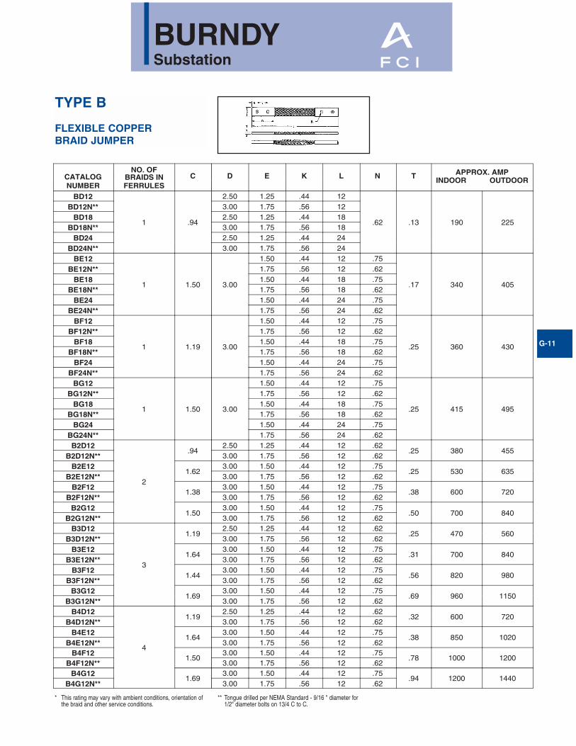
TYPE B
FLEXIBLE COPPER BRAID JUMPER
G-11
* This rating may vary with ambient conditions, orientation ofthe braid and other service conditions.
CATALOGNUMBER
NO. OFBRAIDS INFERRULES
C D E K L N T APPROX. AMPINDOOR OUTDOOR
BD12
1 .94
2.50 1.25 .44 12
.62 .13 190 225
BD12N** 3.00 1.75 .56 12BD18 2.50 1.25 .44 18
BD18N** 3.00 1.75 .56 18BD24 2.50 1.25 .44 24
BD24N** 3.00 1.75 .56 24BE12
1 1.50 3.00
1.50 .44 12 .75
.17 340 405
BE12N** 1.75 .56 12 .62BE18 1.50 .44 18 .75
BE18N** 1.75 .56 18 .62BE24 1.50 .44 24 .75
BE24N** 1.75 .56 24 .62BF12
1 1.19 3.00
1.50 .44 12 .75
.25 360 430
BF12N** 1.75 .56 12 .62BF18 1.50 .44 18 .75
BF18N** 1.75 .56 18 .62BF24 1.50 .44 24 .75
BF24N** 1.75 .56 24 .62BG12
1 1.50 3.00
1.50 .44 12 .75
.25 415 495
BG12N** 1.75 .56 12 .62BG18 1.50 .44 18 .75
BG18N** 1.75 .56 18 .62BG24 1.50 .44 24 .75
BG24N** 1.75 .56 24 .62B2D12
2
.942.50 1.25 .44 12 .62
.25 380 455B2D12N** 3.00 1.75 .56 12 .62
B2E121.62
3.00 1.50 .44 12 .75.25 530 635
B2E12N** 3.00 1.75 .56 12 .62B2F12
1.383.00 1.50 .44 12 .75
.38 600 720B2F12N** 3.00 1.75 .56 12 .62
B2G121.50
3.00 1.50 .44 12 .75.50 700 840
B2G12N** 3.00 1.75 .56 12 .62B3D12
3
1.192.50 1.25 .44 12 .62
.25 470 560B3D12N** 3.00 1.75 .56 12 .62
B3E121.64
3.00 1.50 .44 12 .75.31 700 840
B3E12N** 3.00 1.75 .56 12 .62B3F12
1.443.00 1.50 .44 12 .75
.56 820 980B3F12N** 3.00 1.75 .56 12 .62
B3G121.69
3.00 1.50 .44 12 .75.69 960 1150
B3G12N** 3.00 1.75 .56 12 .62B4D12
4
1.192.50 1.25 .44 12 .62
.32 600 720B4D12N** 3.00 1.75 .56 12 .62
B4E121.64
3.00 1.50 .44 12 .75.38 850 1020
B4E12N** 3.00 1.75 .56 12 .62B4F12
1.503.00 1.50 .44 12 .75
.78 1000 1200B4F12N** 3.00 1.75 .56 12 .62
B4G121.69
3.00 1.50 .44 12 .75.94 1200 1440
B4G12N** 3.00 1.75 .56 12 .62
** Tongue drilled per NEMA Standard - 9/16 " diameter for1/2" diameter bolts on 13/4 C to C.

BURNDYSubstation
G-12
TYPE B
EXPANSION COUPLERASSEMBLY COMPONENTS
FOR COPPER BAR
To build your own expansion coupler assem-bly for single or multiple flat bar(s), usingextra flexible tinned copper braid (shown onpage 9) and clamping hardware, the followingtable has been provided. The assembly takesup longitudinal and lateral motion.
Fig. 1
Fig. 2Fig. 3
① Components ordered separately from Burndy.② See page 9 for flexible copper braid jumper dimensions
and drilling.③ Bars listed are 1/4" thick. Multiple bars are spaced1/4".④ For two hole NEMA drilling in each ferrule add suffix letter
“N” to catalog number of braid jumper as shown on page 9.EXAMPLE: B2E12 drilling is .44 dia. holes on 1 .50"
centers.B2E12N drilling is .56 dia. holes on 1.75"centers.When specifying NEMA drilling bolt diameterin table must be changed from 38 to 50 (lengthis not changed).
CONDUCTORCOPPER BAR
WIDTHNUMBER
APPROXIMATEAMPERE RATING
INDOOR OUTDOOR
EXPANSION COUPLER ASSEMBLY COMPONENTS
FLEXIBLECOPPER
BRAID JUMPER
SILICON BRONZE CLAMPING HARDWARE
BOLTS NUTSSPLIT
LOCKWASHER FLAT WASHER FIGNO.QTY. CAT. NO. QTY CAT. NO. QTY CAT. NO. QTY. CAT. NO. QTY. CAT. NO.
2
1 700 840 2B2E12
4
38X125HEB
4
38CHEN
4
38SW
8
38FW
12 1100 1320 3 38X175HEB3 1600 1920 4 BG12 38X225HEB
4 1800 21603 B2E12
38X250HEB1 B3E12
3
1 1000 1200 4 BG12
8
38X125HEB
8 8 16
2
2 1650 1980 6 B2E12 38X175HEB3 2000 2400 8 BG12 38X225HEB4 2200 2640 8 BG12 38X250HEB
4
1 1350 1620 4 B2E12
8
38X125HEB
8 8 16
2 2250 27002 B2E12
38X225HEB4 B2G12
3 2700 32402 B2G12
38X250HEB6 BG12
4 3000 36004 B2G12
38X325HEB6 BG12
5
1 1600 1920 4 B3E12 8 38X125HEB 8 8 162 2650 3180 9 B2E12
1238X175HEB
12 12 24
3
3 3200 3840 12 BG12 38X225HEB4 3500 4200 15 BG12 38X275HEB
6
1 1900 2280 6 B2E12
12
38X125HEB
12 12 24
2 3150 37803 B2E12
38X175HEB6 B3E12
3 3800 45609 BG12
38X250HEB3 B2G12
4 4200 50409 BG12
38X325HEB6 B2G12
➁➂
➃ ➁
➀
➄
➄
➄
➄
➄
➄
NOTE: Minimum length of each ferrule with NEMA drillingis 3.00".
⑤ Braid jumper ferrule (pad) thickness is larger than 1/4 "requiring assembly to outer contact surface(s) of multiple(1/4 " spaced ) bars.
➅ These ratings may vary with ambient conditions, orientationof the braid and other service conditions.
⑦ For other combinations and configurations of flat barcontact Burndy.
BURNDYSubstation
G-13
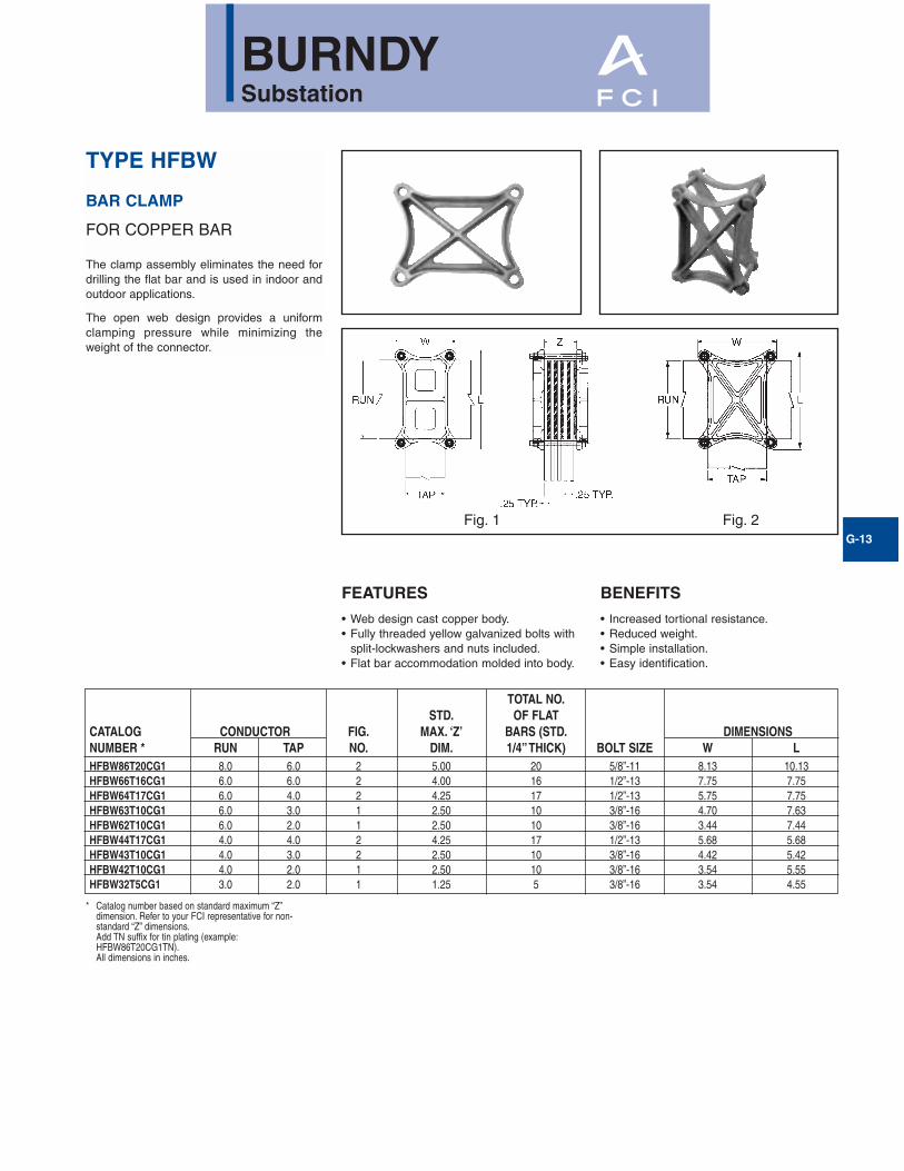
TYPE HFBW
BAR CLAMP
FOR COPPER BAR
The clamp assembly eliminates the need fordrilling the flat bar and is used in indoor andoutdoor applications.
The open web design provides a uniformclamping pressure while minimizing theweight of the connector.
FEATURES
• Web design cast copper body.• Fully threaded yellow galvanized bolts with
split-lockwashers and nuts included.• Flat bar accommodation molded into body.
BENEFITS
• Increased tortional resistance.• Reduced weight.• Simple installation.• Easy identification.
TOTAL NO.STD. OF FLAT
CATALOG CONDUCTOR FIG. MAX. ‘Z’ BARS (STD. DIMENSIONSNUMBER * RUN TAP NO. DIM. 1/4”THICK) BOLT SIZE W LHFBW86T20CG1 8.0 6.0 2 5.00 20 5/8”-11 8.13 10.13HFBW66T16CG1 6.0 6.0 2 4.00 16 1/2”-13 7.75 7.75HFBW64T17CG1 6.0 4.0 2 4.25 17 1/2”-13 5.75 7.75HFBW63T10CG1 6.0 3.0 1 2.50 10 3/8”-16 4.70 7.63HFBW62T10CG1 6.0 2.0 1 2.50 10 3/8”-16 3.44 7.44HFBW44T17CG1 4.0 4.0 2 4.25 17 1/2”-13 5.68 5.68HFBW43T10CG1 4.0 3.0 2 2.50 10 3/8”-16 4.42 5.42HFBW42T10CG1 4.0 2.0 1 2.50 10 3/8”-16 3.54 5.55HFBW32T5CG1 3.0 2.0 1 1.25 5 3/8”-16 3.54 4.55
* Catalog number based on standard maximum “Z”dimension. Refer to your FCI representative for non-standard “Z” dimensions.Add TN suffix for tin plating (example:HFBW86T20CG1TN).All dimensions in inches.
Fig. 1 Fig. 2

BURNDYSubstation
G-14
TYPE HFB-P1
BAR CLAMP ASSEMBLYCOMPONENTS
FOR COPPER BAR
To build your own high strength clamp assem-bly for multiple flat bar using type HFB-P1 barclamps & clamping hardware, the followingtables have been provided. The clampassembly eliminates the need for drilling theflat bar and is used in indoor and outdoorapplications.
ONE CLAMP HALF
BAR CLAMP BUS BAR "J"BOLTDIA. L W
CATALOGNUMBER
RUN’A’
TAP’AA’
HFB33P1 3.00 3.00 3/8 4.38 4.38
HFB44P1 4.00 4.00 1/2 5.75 5.75
HFB63P1 6.00 3.00 1/2 7.75 4.75
HFB66P1 6.00 6.00 5/8 8.12 8.12
HFB88P1 8.00 8.00 3/4 10.50 10.50
BAR CLAMP ASSEMBLY COMPONENTS
COPPERBUS BAR
WIDTH (INCHES) BAR CLAMP
SILICON BRONZE CLAMPING HARDWARE
BOLTS** NUTSSPLIT LOCKWASHERS
RUN-A TAP-AA QTY. CAT. NO. QTY. CAT. NO. QTY. CAT. NO. QTY. CAT. NO.3 3 2 HFB33P1 4 38 X (*) HEB 4 38CHEN 4 38SW4 4 2 HFB44P1 4 50 X (*) HEB 4 50CHEN 4 50SW6 3 2 HFB63P1 4 50 X (*) HEB 4 50CHEN 4 50SW6 6 2 HFB66P1 4 62 X (*) HEB 4 62CHEN 4 62SW8 8 2 HFB88P1 4 75 X (*) HEB 4 75CHEN 4 75SW
BOLT LENGTH**
CLAMPNUMBER
’J’BOLT DIA.
WHENZ=1.25*
WHENZ=1.50*
WHENZ=1.75*
WHENZ=2.00*
WHENZ=2.25*
WHENZ=2.50*
WHENZ=2.75*
WHENZ=3.00*
HFB33P1 3/8"(-16) 3.00 3.25 3.50 4.00 4.00 4.50 4.50 5.00
HFB44P1 1/2"(-13) 3.25 3.50 3.75 4.00 4.50 4.50 5.00 5.00
HFB63P1 1/2"(-13) 3.25 3.50 3.75 4.00 4.50 4.50 5.00 5.00
HFB66P1 5/8"(-11) 3.50 4.00 4.00 4.50 4.50 5.00 5.00 6.00
HFB88P1 3/4"(-10) 3.75 4.00 4.50 4.50 5.00 5.00 5.50 5.50
† Ordered separately from Burndy.* Z = Space between the bar clamp contact surfaces.* *See table below when ordering assembly clamping bolts to
specify correct bolt length in Cat. #.
†
Position for assembly
Bar ClampAssembly
(2) Req’d for assembly
BURNDYSubstation
G-15
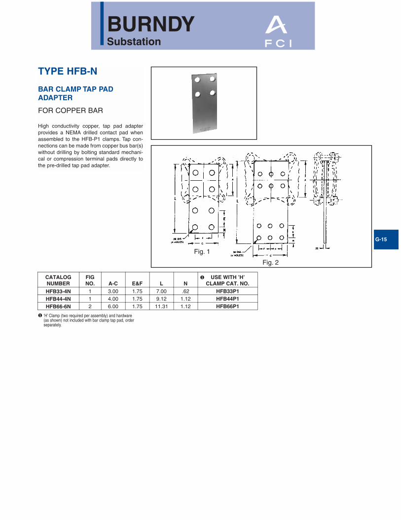
TYPE HFB-N
BAR CLAMP TAP PADADAPTER
FOR COPPER BAR
High conductivity copper, tap pad adapterprovides a NEMA drilled contact pad whenassembled to the HFB-P1 clamps. Tap con-nections can be made from copper bus bar(s)without drilling by bolting standard mechani-cal or compression terminal pads directly tothe pre-drilled tap pad adapter.
CATALOGNUMBER
FIGNO. A-C E&F L N
USE WITH ’H’CLAMP CAT. NO.
HFB33-4N 1 3.00 1.75 7.00 .62 HFB33P1HFB44-4N 1 4.00 1.75 9.12 1.12 HFB44P1HFB66-6N 2 6.00 1.75 11.31 1.12 HFB66P1
❶ ‘H’ Clamp (two required per assembly) and hardware (as shown) not included with bar clamp tap pad, orderseparately.
❶
Fig. 1
Fig. 2
BURNDYSubstation
G-16
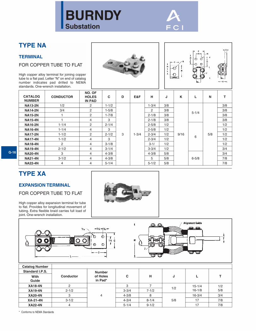
TYPE NA
TERMINAL
FOR COPPER TUBE TO FLAT
High copper alloy terminal for joining coppertube to a flat pad. Letter “N” on end of catalognumber indicates pad drilled to NEMAstandards. One-wrench installation.
CATALOGNUMBER
CONDUCTORNO. OFHOLESIN PAD
C D E&F H J K L N T
NA13-2N 1/2 2 1-1/2
3 1-3/4
1-3/4 3/8
9/16
5-1/4
5/8
3/8
NA14-2N 3/4 2 1-5/8 2 3/8 3/8
NA15-2N 1 2 1-7/8 2-1/8 3/8 3/8
NA15-4N 1 4 3 2-1/8 3/8 3/8
NA16-2N 1-1/4 2 2-1/4 2-5/8 1/2
6
1/2
NA16-4N 1-1/4 4 3 2-5/8 1/2 1/2
NA17-2N 1-1/2 2 2-1/2 2-3/4 1/2 1/2
NA17-4N 1-1/2 4 3 2-3/4 1/2 1/2
NA18-4N 2 4 3-1/8 3-1/ 1/2 1/2
NA19-4N 2-1/2 4 3-1/4 3-3/4 1/2 3/4
NA20-4N 3 4 4-3/8 4-3/8 5/86-5/8
3/4
NA21-4N 3-1/2 4 4-3/8 5 5/8 7/8
NA22-4N 4 4 5-1/4 5-1/2 5/8 7/8
TYPE XA
EXPANSION TERMINAL
FOR COPPER TUBE TO FLAT
High copper alloy expansion terminal for tubeto flat. Provides for longitudinal movement oftubing. Extra flexible braid carries full load ofjoint. One-wrench installation.
Catalog NumberStandard I.P.S.
ConductorNumberof Holesin Pad*
C H J L TWithGuide
XA18-4N 2
4
3 71/2
15-1/416-1/8
1/25/8XA19-4N 2-1/2 3-3/4 7-1/2
XA20-4N 3 4-3/8 85/8
16-3/4 3/4
XA-21-4N 3-1/2 4-3/4 8-1/4 17 7/8
XA22-4N 4 5-1/4 9-1/2 17 7/8
* Conforms to NEMA Standards

BURNDYSubstation
G-17
TYPE NAS/NAH
TERMINAL
FOR COPPER CABLE
High copper alloy reversible cap terminal forjoining a wide range of cable to equipmentpads. Tongue is side formed to provideadequate clearance and terminal is designedfor one-wrench installation.
CATALOGNUMBER
FIG.NO.
COPPER CABLE RANGE
B H J DIA. L T WCOMPLETE
CABLE RANGESMALL
GROOVELARGE
GROOVE
NAS29-N 1B
6 SOL. (.162 DIA.) TO250 kcmil (.575 DIA)
6 SOL. (.162 DIA.) TO1/0 STR. (.373 DIA.)
2/0 STR. (.419 DIA.) TO250 kcmil (.575 DIA)
2.38 1.80 3/8"-163.585.62
.25
2.00NAS29-2N 1D
NAH29-2N 1D 2.62 2.12 1/2"-13 5.88 2.44
NAS29-34N 1E
2.38
1.80
3/8"-16
5.62 2.00
NAS34-N 1C
1/0 SOL. (.325 DIA.) TO500 kcmil (.813 DIA.)
1/0 SOL. (.325 DIA.) TO4/0 STR. (.529 DIA.)
250 kcmil (.575 DIA.) TO500 kcmil (.813 DIA.)
2.054.12
2.20NAS34-2N 1A 5.62.31NAH34-2N 1A 2.62 2.38 1/2"-13 5.88 2.56
NAS34-34N 1E 2.38 2.05 3/8"-16 5.62
.25
2.20
NAH34-34N 1E
2.62
2.30 1/2"-13
5.88
2.56NAS40-2N 1A
2/0 SOL. (.365 DIA.) TO800 kcmil (1.031 DIA.)
2/0 SOL. (.365 DIA.) TO500 kcmil (.813 DIA.)
500 kcmil (.813 DIA.) TO800 kcmil (1.031 DIA)
2.30 3/8"-16
.382.44
NAH40-2N 1A 2.62 1/2"-13 2.81
NAS40-34N 1E 2.30 3/8"-16
.31
2.44
NAH40-34N 1E 2.62 1/2"-13
2.81NAS40-44N 1 2.30 3/8"-16
6.88NAH40-44N 1
2.62
1/2"-13
2.44
NAH44-2N 1A
4/0 STR. (.528DIA) TO1000 kcmil (1.152 DIA)
4/0 STR. (.528 DIA.) TO750 kcmil (.998 DIA.)
750 kcmil (.998 DIA.) TO1000 kcmil (1.152 DIA.) 2.88
2.81NAH44-34N 1E
NAH44-44N 16.12
.44
.38 2.88NAH46-2N 1A1000 kcmil (1.152 DIA.)
TO 1500 kcmil(1.412 DIA.)
—1000 kcmil (1.152 DIA.)
TO 1500 kcmil(1.412 DIA.)
3.06 2.88NAH46-34N 1E7.12 .31
6.31.50.41 3.19NAH46-44N 1
NAH48-2N 1A500 kcmil (.813 DIA.) TO2000 kcmil (1.632 DIA.)
500 kcmil (.813 DIA.) TO1500 kcmil (1.412 DIA.)
1500 kcmil (1.412 DIA.)TO 2000 kcmil (1.632
DIA.)3.25 3.12
7.31 .38
NAH48-34N 1E 6.50 .69.50 3.38
NAH48-44N 1 7.50 .44
Fig. 1
Fig. “A” Fig. “B” Fig. “C”
Fig. “D” Fig. “E”

BURNDYSubstation
G-18
TYPE N2AH
TERMINAL
FOR TWO COPPER CABLES TO FLAT
High copper alloy, reversible cap terminal forjoining a wide range of two copper cables toequipment pads. Tongue is side formed toprovide adequate clearance and terminal isdesigned for one-wrench installation.
CATALOGNUMBER
FIG.NO.
COPPER CABLE RANGE DIMENSIONS IN/(mm)
COMPLETECABLE RANGE
SMALLGROOVE
LARGEGROOVE B H J DIA. L T W
N2AH34-34N 1 1/0 STR. (.325) TO500 kcmil (.813)
1/0 SOL (.325) TO4/0 STR. (.529)
250 kcmil (.575) TO500 kcmil (.813)
2.63(67)
2.30(58)
1/2 - 13
6.13(156)
.31(8)
3.88(99)
N2AH40-34N 12/0 STR. (.420) TO800 kcmil (1.031)
2/0 STR. (.420) TO500 kcmil (.813)
500 kcmil (.813) TO800 kcmil (1.031)
2.63(67)
2.62(67)
5.88(149)
.31(8)
5.70(145)
N2AH44-34N 14/0 STR. (.529) TO1000 kcmil (1.152)
4/0 STR. (.529) TO750 kcmil (.998)
750 kcmil (.998) TO1000 kcmil (1.152)
2.88(73)
2.62(67)
6.38(175)
.50(13)
4.69(119)
N2AH44-44N 24/0 STR. (.529) TO1000 kcmil (1.152)
4/0 SOL. (.529) TO750 kcmil (.998)
750 kcmil (.998) TO1000 kcmil (1.152)
2.88(73)
2.25(57)
7.32(186)
.50(13)
6.12(155)
N2AH46-44N 21000 kcmil (1.152) TO
1500 kcmil (1.411)- -
3.07(78)
2.50(64)
7.46(189)
.75(19)
6.50(165)
Fig. 1 Fig. 2
BURNDYSubstation
G-19
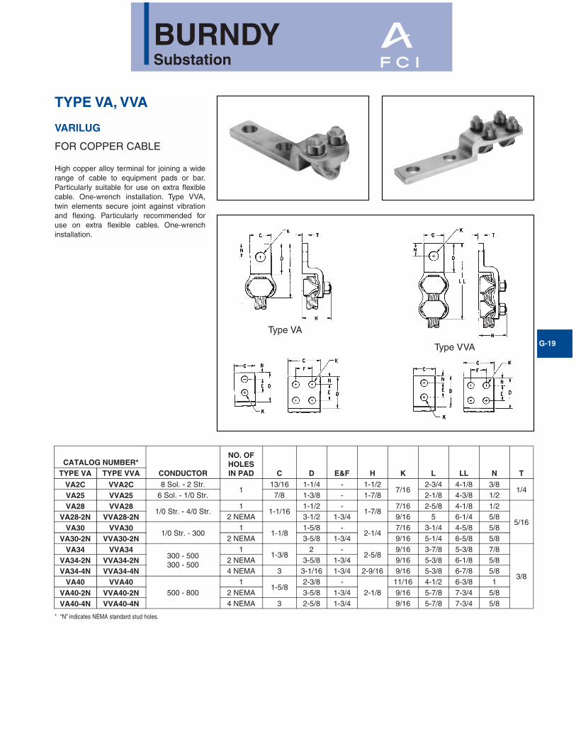
TYPE VA, VVA
VARILUG
FOR COPPER CABLE
High copper alloy terminal for joining a widerange of cable to equipment pads or bar.Particularly suitable for use on extra flexiblecable. One-wrench installation. Type VVA,twin elements secure joint against vibrationand flexing. Particularly recommended foruse on extra flexible cables. One-wrenchinstallation.
CATALOG NUMBER*CONDUCTOR
NO. OFHOLESIN PAD C D E&F H K L LL N TTYPE VA TYPE VVA
VA2C VVA2C 8 Sol. - 2 Str.1
13/16 1-1/4 - 1-1/27/16
2-3/4 4-1/8 3/81/4
VA25 VVA25 6 Sol. - 1/0 Str. 7/8 1-3/8 - 1-7/8 2-1/8 4-3/8 1/2
VA28 VVA281/0 Str. - 4/0 Str.
11-1/16
1-1/2 -1-7/8
7/16 2-5/8 4-1/8 1/2
5/16VA28-2N VVA28-2N 2 NEMA 3-1/2 1-3/4 9/16 5 6-1/4 5/8
VA30 VVA301/0 Str. - 300
11-1/8
1-5/8 -2-1/4
7/16 3-1/4 4-5/8 5/8
VA30-2N VVA30-2N 2 NEMA 3-5/8 1-3/4 9/16 5-1/4 6-5/8 5/8
VA34 VVA34300 - 500300 - 500
11-3/8
2 -2-5/8
9/16 3-7/8 5-3/8 7/8
3/8
VA34-2N VVA34-2N 2 NEMA 3-5/8 1-3/4 9/16 5-3/8 6-1/8 5/8
VA34-4N VVA34-4N 4 NEMA 3 3-1/16 1-3/4 2-9/16 9/16 5-3/8 6-7/8 5/8
VA40 VVA40500 - 800
11-5/8
2-3/8 -2-1/8
11/16 4-1/2 6-3/8 1
VA40-2N VVA40-2N 2 NEMA 3-5/8 1-3/4 9/16 5-7/8 7-3/4 5/8
VA40-4N VVA40-4N 4 NEMA 3 2-5/8 1-3/4 9/16 5-7/8 7-3/4 5/8
* “N” indicates NEMA standard stud holes.
Type VA
Type VVA

BURNDYSubstation
G-20
TYPE UH
BUS SUPPORT
FOR COPPER TUBE
High copper alloy bus support for mountingtube on a post or pedestal type insulator.Single bolt allows rotation to any angle.Rotate cap 180° for slip or rigid fit. One-wrench installation. Supplied with hardwarefor mounting to cap of insulator. Specify basemounting hardware, if required, by addingsuffix “B” to Catalog No.
CATALOGNUMBER
COPPERCONDUCTOR
IPS "A"BOLT
CIRCLE B G H J K WUH14-3 3/4 3
2-1/22 2-7/8
3/89/16 2-5/8
UH15-31
3 2 3 9/162-7/8
UH15-5 52-1/4
3-1/4 11/16UH16-3
1-1/43
2-11/163-1/2
1/2
9/163-1/2
UH16-5 5 2-3/8 3-5/8 11/16UH17-3
1-1/23
3
2-1/2 3-7/89/16
4UH17-5 5 11/16UH18-3
23
2-3/4 4-3/89/16
4-5/8UH18-5 5 11/16UH19-3
2-1/23
3-1/8 59/16
5-1/4UH19-5 5 11/16UH20-3
33
3-1/43-5/8 5-7/8
5/8
9/166-1/4
UH20-5 5 11/16UH21-5 3-1/2 5 4 6-1/2 11/16 6-7/8UH22-5 4 5 4-1/2 7-1/4 11/16 7-1/2
CatalogNumber
Copper Conductor "A"Bolt
CircleB G* H J K W
Cable Tube
UHR13-36 Str. - 500 1/8 - 1/2
33-5/8
1-3/4 3
3/8
9/162-1/4
UHR13-5 5 2-1/8 3-3/8 11/16
UHR15-34/0 Str. - 1250 1/4 - 1
33-3/4
2 3-1/2 9/162-3/4
UHR15-5 5 2-1/4 3-3/4 11/16
UHR17-3750 - 2500 3/4 - 1-1/2
32-7/8 2-1/2 4-1/4 1/2
9/164
UHR17-5 5 11/16
TYPE UHR
BUS SUPPORT
FOR COPPER CABLE OR TUBE
High copper alloy bus support clamp formounting a wide range of cable or tube onpost or pedestal type insulators. Single boltallows rotation to any angle. Supplied withhardware for mounting to cap of insulator.Specify base mounting hardware, if required,by adding suffix “-B” to Catalog No.
* With maximum conductor in place.
BURNDYSubstation
G-21
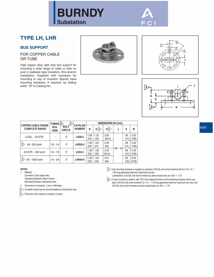
NOTES:1 Material:
Connector: Cast copper alloyClamping Hardware: Silicon bronzeMounting Hardware: Galvanized steel
2 Dimensions in brackets [ ] are in millimeters.
3 Complete range may be accommodated by reversing the cap.
4 Dimension with maximum conductor in place.
TYPE LH, LHR
BUS SUPPORT
FOR COPPER CABLE OR TUBE
High copper alloy, light duty bus support formounting a wide range of cable or tube onpost or pedestal type insulators. One-wrenchinstallation. Supplied with hardware formounting to cap of insulator. Specify basemounting hardware, if required, by addingsuffix “-B” to Catalog No.
5 Cap mounting hardware is supplied as standard. 3.00 Dia. bolt circle furnished with four 1/2 -13 �
1.00 long galvanized steel hex head bolts and shp.Lockwashers. 5.00 Dia. bolt circle furnished as above except bolts are .625 � 1.75.
6 If base mounting is desired, add “-B” to the Catalog Number and the following hardware will be sup-plied: 3.00 Dia. bolt circle furnished 1/2 -13 � 11/2 long galvanized steel hex head bolt, hex nuts, and5.00 Dia. bolt circle furnished as above except bolts are .625 � 1.75.
COPPER CABLE RANGE COMPLETE RANGE
TUBINGSCH.40/80
BOLTCIRCLE
CATALOGNUMBER
DIMENSIONS IN/ [mm]
B G H J K W
6 SOL. - 4/0 STR. - 3" LH28-31.69[43]
1.25 [32]
2.62 [66.5]
3/8 - 16
.56 [14]
4.25 [108]
#8 - 250 kcmil 1/8 - 1/4 3" LHR29-31.00
[25]1.23 [31]
2.03[52]
.56 [14]
4.25 [108]
2/0 STR. - 500 kcmil 1/4 - 1/2 3" LH34-31.38 [35]
1.38 [35]
2.50 [63.5]
.56 [14]
4.25[108]
4/0 - 1000 kcmil 1/4 - 3/4 5" LHR44-51.00 [25]
1.33 [34]
2.51 [64]
.69 [18]
6.25 [159]
3
5 6
4 4
3
BURNDYSubstation
G-22
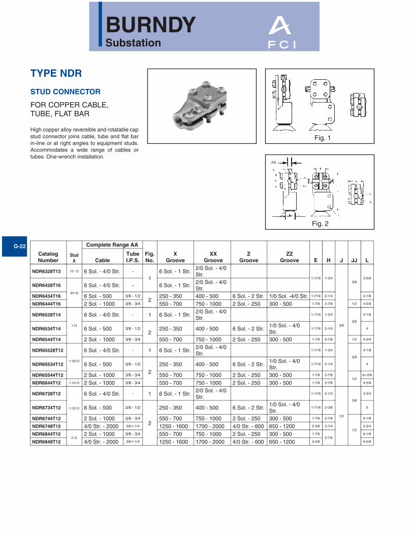
TYPE NDR
STUD CONNECTOR
FOR COPPER CABLE, TUBE, FLAT BAR
High copper alloy reversible and rotatable capstud connector joins cable, tube and flat barin-line or at right angles to equipment studs.Accommodates a wide range of cables ortubes. One-wrench installation.
CatalogNumber
StudA
Complete Range AA
Fig.No.
XGroove
XXGroove
ZGroove
ZZGroove E H J JJ LCable
TubeI.P.S.
NDR6328T13 1/2 -13 6 Sol. - 4/0 Str. -1
6 Sol. - 1 Str.2/0 Sol. - 4/0Str.
1-1/16 1-3/4
3/8
3/83-5/8
NDR6428T16
3/4-16
6 Sol. - 4/0 Str. - 6 Sol. - 1 Str.2/0 Sol. - 4/0Str.
NDR6434T16 6 Sol. - 500 3/8 - 1/22
250 - 350 400 - 500 6 Sol. - 2 Str. 1/0 Sol. -4/0 Str. 1-7/16 2-1/4 4-1/8
NDR6444T16 2 Sol. - 1000 3/8 - 3/4 550 - 700 750 - 1000 2 Sol. - 250 300 - 500 1-7/8 2-7/8 1/2 4-5/8
NDR6528T14
1-14
6 Sol. - 4/0 Str. - 1 6 Sol. - 1 Str.2/0 Sol. - 4/0Str.
1-1/16 1-3/4
3/8
4-1/8
NDR6534T14 6 Sol. - 500 3/8 - 1/22
250 - 350 400 - 500 6 Sol. - 2 Str.1/0 Sol. - 4/0Str.
1-7/16 2-1/4 4
NDR6544T14 2 Sol. - 1000 3/8 - 3/4 550 - 700 750 - 1000 2 Sol. - 250 300 - 500 1-7/8 2-7/8 1/2 4-3/4
NDR65528T12
1-1/8-12
6 Sol. - 4/0 Str. - 1 6 Sol. - 1 Str.2/0 Sol. - 4/0Str.
1-1/16 1-3/4
3/8
4-1/8
NDR65534T12 6 Sol. - 500 3/8 - 1/2
2250 - 350 400 - 500 6 Sol. - 2 Str.
1/0 Sol. - 4/0Str.
1-7/16 2-1/4 4
NDR65544T12 2 Sol. - 1000 3/8 - 3/4 550 - 700 750 - 1000 2 Sol. - 250 300 - 500 1-7/8 2-7/81/2
4=-5/8
NDR6644T12 1-1/4-12 2 Sol. - 1000 3/8 - 3/4 550 - 700 750 - 1000 2 Sol. - 250 300 - 500 1-7/8 2-7/8 4-5/8
NDR6728T12
1-1/2-12
6 Sol. - 4/0 Str. - 1 6 Sol. - 1 Str.2/0 Sol. - 4/0Str.
1-1/16 2-1/4
1/2
3/8
4-3/4
NDR6734T12 6 Sol. - 500 3/8 - 1/2
2
250 - 350 400 - 500 6 Sol. - 2 Str.1/0 Sol. - 4/0Str.
1-7/16 2-3/8 5
NDR6744T12 2 Sol. - 1000 3/8 - 3/4 550 - 700 750 - 1000 2 Sol. - 250 300 - 500 1-7/8 2-7/8
1/2
5-1/8
NDR6748T12 4/0 Str. - 2000 3/8-1-1/4 1250 - 1600 1700 - 2000 4/0 Str. - 600 650 - 1200 2-3/8 3-1/4 5-3/4
NDR6844T122-12
2 Sol. - 1000 3/8 - 3/4 550 - 700 750 - 1000 2 Sol. - 250 300 - 500 1-7/82-7/8
6-1/8
NDR6848T12 4/0 Str. - 2000 3/8-1-1/4 1250 - 1600 1700 - 2000 4/0 Str. - 600 650 - 1200 2-3/8 6-5/8
Fig. 1
Fig. 2
BURNDYSubstation
G-23
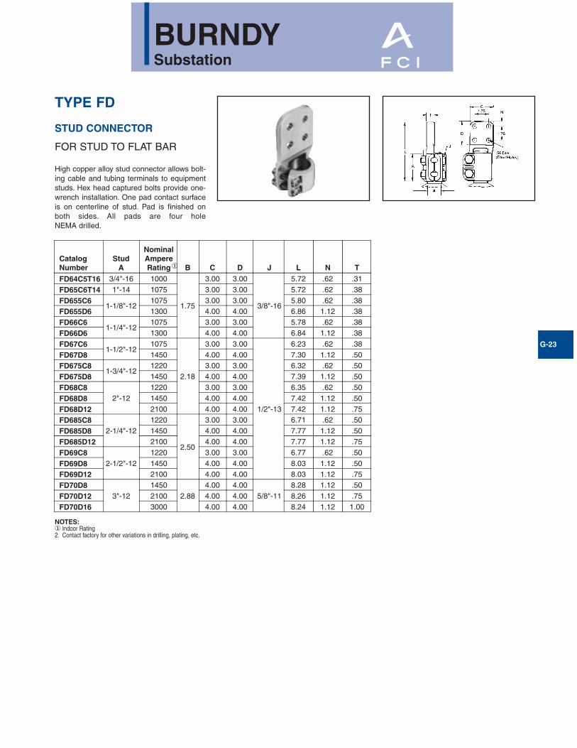
TYPE FD
STUD CONNECTOR
FOR STUD TO FLAT BAR
High copper alloy stud connector allows bolt-ing cable and tubing terminals to equipmentstuds. Hex head captured bolts provide one-wrench installation. One pad contact surfaceis on centerline of stud. Pad is finished onboth sides. All pads are four hole NEMA drilled.
NOTES:① Indoor Rating2. Contact factory for other variations in drilling, plating, etc.
CatalogNumber
StudA
NominalAmpereRating B C D J L N T
FD64C5T16 3/4"-16 1000
1.75
3.00 3.00
3/8"-16
5.72 .62 .31
FD65C6T14 1"-14 1075 3.00 3.00 5.72 .62 .38
FD655C61-1/8"-12
1075 3.00 3.00 5.80 .62 .38
FD655D6 1300 4.00 4.00 6.86 1.12 .38
FD66C61-1/4"-12
1075 3.00 3.00 5.78 .62 .38
FD66D6 1300 4.00 4.00 6.84 1.12 .38
FD67C61-1/2"-12
1075
2.18
3.00 3.00
1/2"-13
6.23 .62 .38
FD67D8 1450 4.00 4.00 7.30 1.12 .50
FD675C81-3/4"-12
1220 3.00 3.00 6.32 .62 .50
FD675D8 1450 4.00 4.00 7.39 1.12 .50
FD68C82"-12
1220 3.00 3.00 6.35 .62 .50
FD68D8 1450 4.00 4.00 7.42 1.12 .50
FD68D12 2100 4.00 4.00 7.42 1.12 .75
FD685C82-1/4"-12
1220
2.50
3.00 3.00 6.71 .62 .50
FD685D8 1450 4.00 4.00 7.77 1.12 .50
FD685D12 2100 4.00 4.00 7.77 1.12 .75
FD69C82-1/2"-12
1220 3.00 3.00 6.77 .62 .50
FD69D8 1450 4.00 4.00 8.03 1.12 .50
FD69D12 2100 4.00 4.00 8.03 1.12 .75
FD70D83"-12
14502.88
4.00 4.005/8"-11
8.28 1.12 .50
FD70D12 2100 4.00 4.00 8.26 1.12 .75
FD70D16 3000 4.00 4.00 8.24 1.12 1.00
①
BURNDYSubstation
G-24
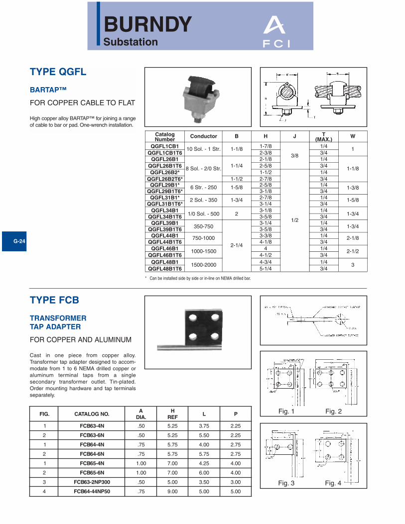
TYPE QGFL
BARTAP™
FOR COPPER CABLE TO FLAT
High copper alloy BARTAP™ for joining a rangeof cable to bar or pad. One-wrench installation.
CatalogNumber
Conductor B H J T(MAX.)
W
QGFL1CB1 10 Sol. - 1 Str. 1-1/8 1-7/8
3/8
1/4 1QGFL1CB1T6 2-3/8 3/4
QGFL26B1
8 Sol. - 2/0 Str. 1-1/42-1/8 1/4
1-1/8QGFL26B1T6 2-5/8 3/4QGFL26B2* 1-1/2
1/2
1/4QGFL26B2T6* 1-1/2 2-7/8 3/4
QGFL29B1* 6 Str. - 250 1-5/8 2-5/8 1/4 1-3/8QGFL29B1T6* 3-1/8 3/4
QGFL31B1* 2 Sol. - 350 1-3/4 2-7/8 1/4 1-5/8QGFL31B1T6* 3-1/4 3/4
QGFL34B11/0 Sol. - 500 2
3-1/8 1/41-3/4QGFL34B1T6 3-5/8 3/4
QGFL39B1350-750
2-1/4
3-1/4 1/41-3/4QGFL39B1T6 3-5/8 3/4
QGFL44B1 750-1000 3-3/8 1/4 2-1/8QGFL44B1T6 4-1/8 3/4
QGFL46B1 1000-1500 4 1/4 2-1/2QGFL46B1T6 4-1/2 3/4
QGFL48B1 1500-2000 4-3/4 1/4 3QGFL48B1T6 5-1/4 3/4
TYPE FCB
TRANSFORMER TAP ADAPTER
FOR COPPER AND ALUMINUM
Cast in one piece from copper alloy.Transformer tap adapter designed to accom-modate from 1 to 6 NEMA drilled copper oraluminum terminal taps from a single secondary transformer outlet. Tin-plated.Order mounting hardware and tap terminalsseparately.
.GIF .ONGOLATACA
.AIDH
FERL P
1 N4-36BCF 05. 52.5 57.3 52.2
2 N6-36BCF 05. 52.5 05.5 52.2
1 N4-46BCF 57. 57.5 00.4 57.2
2 N6-46BCF 57. 57.5 57.5 57.2
1 N4-56BCF 00.1 00.7 52.4 00.4
2 N6-56BCF 00.1 00.7 00.6 00.4
3 003PN2-36BCF 05. 00.5 05.3 00.3
4 05PN44-46BCF 57. 00.9 00.5 00.5
* Can be installed side by side or in-line on NEMA drilled bar.
Fig. 1 Fig. 2
Fig. 3 Fig. 4

BURNDYSubstation
G-25
TYPE E-C-G
TRANSFORMER TAP ADAPTER
FOR COPPER CABLE
Multi-tap, range-taking cast copper alloy con-nector designed to take 2, 3, or 4 conductorsfrom a single secondary transformer outlet.
CATALOGNUMBER
NO. OFCONDUCTORS CONDUCTOR SIZE
ADIA. D H J L W
E2C34G1 21/0 Sol.-to 500 .78 3-3/4 3-7/8 1/2-13 6-1/4
3-1/2
E3C34G1 3 5-1/4
E4C34G1 4 6-7/8
Catalog NumberType FN
Stud Dia. AndThreads per Inch
CF(Cross Flats) H T W
FN62T16 3/8 - 16 3/4 3/8 5/16 7/8
FN63T13 1/2 - 13 1 15/32 3/8 1-1/4
FN64T16 3/4 - 16 1-1/4 3/4 9/16 1-1/2
FN655T12 1-1/8 - 12 1-3/4 1 3/4 2-1/8
FN66T14 1-1/4 - 14 21-1/8 7/8
2-3/8
FN67T12 1-1/2 - 12 2-3/8 2-3/4
TYPE FN
CONTACT NUT
FLAT TO STUD
High copper alloy contact nut for joining bar orterminal pads to studs. Designed to carry fullcurrent load from flat to stud.

BURNDYSubstation
G-26
CONNECTORS FOR ALUMINUM CONDUCTORS
Bolted aluminum connectors are cast of alu-minum alloy and assembled with aluminumalloy bolts, nuts and galvanized steelwashers. The hex head bolts are captured forone-wrench installation. The connectorsaccommodate aluminum or copper conduc-tor. The “mass anode” design pioneered byBURNDY minimizes the effect of galvanic cor-rosion on aluminum (anode+) connectorswhen used with copper (cathode –) conductor(Reference Fig. 1).
Joint deterioration caused by relaxation or“cold flow” of the aluminum is eliminated bythe massive design. Generous contact areasdistribute clamping forces evenly over theconductor, eliminating points of high stressthat cause “cold flow.” These contact areasare factory treated to remove surface oxidesand coated with an oxide inhibitor to preventtheir reformation. Large radiating surfacesallow the connectors to run cooler than thecopper conductor compensating for the factthat aluminum has a higher coefficient of ther-mal expansion. Connector and conductorexpand and contract together during loadcycles, eliminating stresses on the aluminumbody that can cause relaxation of the joint.
CONNECTOR SELECTION
Generally, copper connectors are recom-mended for copper conductor and aluminumconnectors for aluminum conductor. Wherealuminum connectors are recommended foruse on both aluminum and copper conduc-tors, the copper must be positioned parallel toor below the aluminum to prevent contamina-tion of the aluminum by copper salts washeddown by rain.
Except where indicated, all rigid connectorsaccept standard or extra heavy I.P.S. and allflexible connectors standard I.P.S. If extraheavy I.P.S. is to be used with a flexible joint,it must be spelled out at the time of orderingso that the proper cross sectional area of theflexible element may be supplied for theincreased conductor rating.
CONDUCTOR PREPARATION
To obtain optimum performance from anyconnector, the conductor surface must bethoroughly cleaned before installation. Thesurface oxides that form on all conductors actas insulation. Failure to remove them can result in high resistance joint and, ulti-mately, failure.
Conductor contact surfaces should bescratch brushed until bright and shiny.Aluminum conductor (new or old) should becoated with BURNDY PENETROX® afterscratch brushing. PENETROX® is a joint com-pound that aids in the establishment of lowresistance joints and prevents aluminumoxides from reforming.
ALUMINUM INTRODUCTION
Fig. 1
Many aluminum ionsremoved by current flow
Few aluminum ions removedby current flow
Copper Cathode
Aluminum Anode
Aluminum Anode
Copper Cathode
BURNDYSubstation
G-27
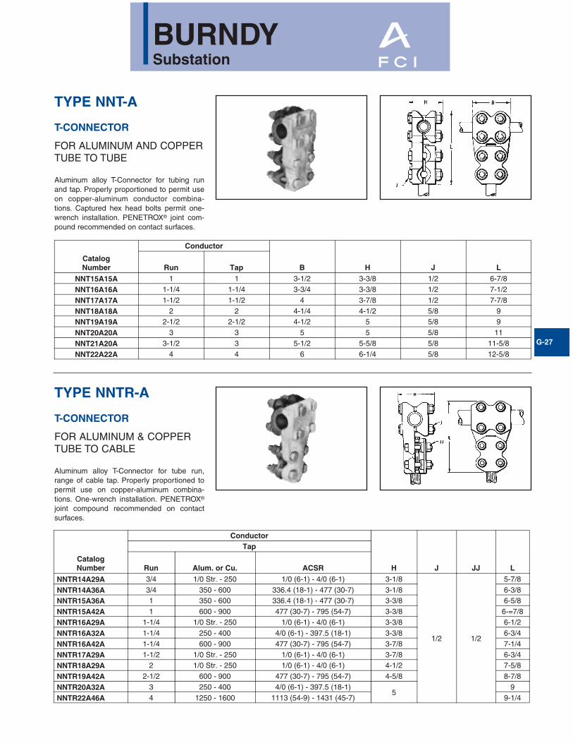
TYPE NNT-A
T-CONNECTOR
FOR ALUMINUM AND COPPERTUBE TO TUBE
Aluminum alloy T-Connector for tubing runand tap. Properly proportioned to permit useon copper-aluminum conductor combina-tions. Captured hex head bolts permit one-wrench installation. PENETROX® joint com-pound recommended on contact surfaces.
TYPE NNTR-A
T-CONNECTOR
FOR ALUMINUM & COPPERTUBE TO CABLE
Aluminum alloy T-Connector for tube run,range of cable tap. Properly proportioned topermit use on copper-aluminum combina-tions. One-wrench installation. PENETROX®
joint compound recommended on contactsurfaces.
CatalogNumber
Conductor
B H J LRun Tap
NNT15A15A 1 1 3-1/2 3-3/8 1/2 6-7/8
NNT16A16A 1-1/4 1-1/4 3-3/4 3-3/8 1/2 7-1/2
NNT17A17A 1-1/2 1-1/2 4 3-7/8 1/2 7-7/8
NNT18A18A 2 2 4-1/4 4-1/2 5/8 9
NNT19A19A 2-1/2 2-1/2 4-1/2 5 5/8 9
NNT20A20A 3 3 5 5 5/8 11
NNT21A20A 3-1/2 3 5-1/2 5-5/8 5/8 11-5/8
NNT22A22A 4 4 6 6-1/4 5/8 12-5/8
CatalogNumber
Conductor
H J JJ L
Tap
Run Alum. or Cu. ACSR
NNTR14A29A 3/4 1/0 Str. - 250 1/0 (6-1) - 4/0 (6-1) 3-1/8
1/2 1/2
5-7/8
NNTR14A36A 3/4 350 - 600 336.4 (18-1) - 477 (30-7) 3-1/8 6-3/8
NNTR15A36A 1 350 - 600 336.4 (18-1) - 477 (30-7) 3-3/8 6-5/8
NNTR15A42A 1 600 - 900 477 (30-7) - 795 (54-7) 3-3/8 6-=7/8
NNTR16A29A 1-1/4 1/0 Str. - 250 1/0 (6-1) - 4/0 (6-1) 3-3/8 6-1/2
NNTR16A32A 1-1/4 250 - 400 4/0 (6-1) - 397.5 (18-1) 3-3/8 6-3/4
NNTR16A42A 1-1/4 600 - 900 477 (30-7) - 795 (54-7) 3-7/8 7-1/4
NNTR17A29A 1-1/2 1/0 Str. - 250 1/0 (6-1) - 4/0 (6-1) 3-7/8 6-3/4
NNTR18A29A 2 1/0 Str. - 250 1/0 (6-1) - 4/0 (6-1) 4-1/2 7-5/8
NNTR19A42A 2-1/2 600 - 900 477 (30-7) - 795 (54-7) 4-5/8 8-7/8
NNTR20A32A 3 250 - 400 4/0 (6-1) - 397.5 (18-1)5
9
NNTR22A46A 4 1250 - 1600 1113 (54-9) - 1431 (45-7) 9-1/4

BURNDYSubstation
G-28
TYPE NNTR-A
T-CONNECTOR
FOR ALUMINUM AND COPPERCABLE TO CABLE
Aluminum alloy T-Connector for a range ofcopper, aluminum and ACSR cable on runand tap. Properly proportioned to permit useon copper-aluminum conductor com-binations. One-wrench installation. PENE-TROX® joint compound recommended oncontact surfaces.
TYPE NS-A
COUPLER
FOR ALUMINUM AND COPPERTUBE TO TUBE
Aluminum alloy coupler for joining equal sizesof tube end to end. Properly proportioned topermit use on aluminum-copper conductorcombinations. One-wrench installation.PENETROX® joint compound recommendedon contact surfaces.
CATALOGNUMBER
CONDUCTORI.P.S.
FIG.NO.
J L
NS14A14A 3/4
1
1/26-3/4
NS15A15A 1 7-1/4
NS17A17A 1-1/2 8-1/4
NS18A18A 2
5/8
8-3/4
NS19A19A 2-1/2 9-1/4
NS20A20A 3 10-1/4
NS21A21A 3-1/2 11-1/4
NS22A22A 4 12-1/4
NS24A24A 5 2 14-1/4
CatalogNo.
Conductor
Fig.No. B H J L
Run TapAlum. orCopper ACSR
Alum. orCopper ACSR
NNTR29A29A 1/0 Str.-250 1/0 (6-1)-4/0 (6-1) 1/0 Str.-250 1/0 (6-1)-4/0 (6-1) 2 2-3/4 2-5/8
1/2
5-5/8
NNTR32A25A 250-400 4/0 (6-1)-397.5 (18.1) 4 Str.-1/0 Str. 4 (6-1)-1/0 (6-1) 1 1-7/8 2-5/8 4-7/8
NNTR32A32A 250-400 4/0 (6-1)-397.5 (18-1) 250-400 4/0(6-1)-397.5(18-1) 2 3 2-5/8 6
NNTR36A25A 350-600 336.4(18-1)-477(30-7) 4 Str.-1/0 Str. 4 (6-1) - 1/0 (6-1) 1 1-7/8 2-5/8 5
NNTR36A29A 350-600 336.4(18-1)-477(30-7) 1/0 Str.-250 1/0(6-1)-4/0(6-1) 2 3-1/4 2-5/8 5-7/8
NNTR36A36A 350-600 336.4(18-1)-477(30.7) 350-600 336.4(18-1)-477(30-7) 2 3-1/4 2-5/8 6-3/8
NNTR42A32A 600-900 477(30-7)-795(54-7) 250-400 4/0(6-1)-397.5(18-1) 2 3-1/2 3-1/8 6-3/8
NNTR42A36A 600-900 477(30-7)-795(54-7) 350-600 336.4(18-1)-477(30.7) 2 3-1/2 3-1/8 6-5/8
NNTR42A42A 600-900 477(30-7)-795(54-7) 600-900 477(30-7)-795(54-7) 2 3-1/2 3-1/8 6-7/8
NNTR45A45A 900-1250 715.5(30-19)-1113(54-19) 900-1250 715.5(30-19)-1113(54-19)9 2 3-3/4 31/4 7-3/8
NNTR46A42A 1250-1600 1113(54-19)-1431(45-7) 600-900 477(30-7)-795(54-7) 2 3-3/4 3-1/2 7-1/4
NNTR46A46A 1250-1600 1113(54-19)-1431(45-7) 1250-1600 1113(54-19)-1431(45-7) 2 4-3/8 3-3/4 5/8 8-3/8
NNTR48A48A 1500-2000 1272(54-19)-1780(84-19) 1500-2000 1272(54-19)-1780(84-19) 2 4-3/8 3-7/8 5/8 8-5/8
Fig. 1
Fig. 2
Fig. 1 Fig. 2
BURNDYSubstation
G-29
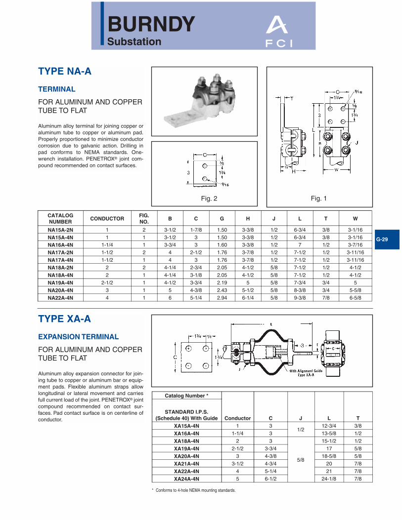
TYPE NA-A
TERMINAL
FOR ALUMINUM AND COPPERTUBE TO FLAT
Aluminum alloy terminal for joining copper oraluminum tube to copper or aluminum pad.Properly proportioned to minimize conductorcorrosion due to galvanic action. Drilling inpad conforms to NEMA standards. One-wrench installation. PENETROX® joint com-pound recommended on contact surfaces.
TYPE XA-A
EXPANSION TERMINAL
FOR ALUMINUM AND COPPERTUBE TO FLAT
Aluminum alloy expansion connector for join-ing tube to copper or aluminum bar or equip-ment pads. Flexible aluminum straps allowlongitudinal or lateral movement and carriesfull current load of the joint. PENETROX® jointcompound recommended on contact sur-faces. Pad contact surface is on centerline ofconductor.
CATALOGNUMBER
CONDUCTORFIG.NO.
B C G H J L T W
NA15A-2N 1 2 3-1/2 1-7/8 1.50 3-3/8 1/2 6-3/4 3/8 3-1/16
NA15A-4N 1 1 3-1/2 3 1.50 3-3/8 1/2 6-3/4 3/8 3-1/16
NA16A-4N 1-1/4 1 3-3/4 3 1.60 3-3/8 1/2 7 1/2 3-7/16
NA17A-2N 1-1/2 2 4 2-1/2 1.76 3-7/8 1/2 7-1/2 1/2 3-11/16
NA17A-4N 1-1/2 1 4 3 1.76 3-7/8 1/2 7-1/2 1/2 3-11/16
NA18A-2N 2 2 4-1/4 2-3/4 2.05 4-1/2 5/8 7-1/2 1/2 4-1/2
NA18A-4N 2 1 4-1/4 3-1/8 2.05 4-1/2 5/8 7-1/2 1/2 4-1/2
NA19A-4N 2-1/2 1 4-1/2 3-3/4 2.19 5 5/8 7-3/4 3/4 5
NA20A-4N 3 1 5 4-3/8 2.43 5-1/2 5/8 8-3/8 3/4 5-5/8
NA22A-4N 4 1 6 5-1/4 2.94 6-1/4 5/8 9-3/8 7/8 6-5/8
Catalog Number *
Conductor C J L TSTANDARD I.P.S.
(Schedule 40) With GuideXA15A-4N 1 3
1/212-3/4 3/8
XA16A-4N 1-1/4 3 13-5/8 1/2
XA18A-4N 2 3
5/8
15-1/2 1/2
XA19A-4N 2-1/2 3-3/4 17 5/8
XA20A-4N 3 4-3/8 18-5/8 5/8
XA21A-4N 3-1/2 4-3/4 20 7/8
XA22A-4N 4 5-1/4 21 7/8
XA24A-4N 5 6-1/2 24-1/8 7/8
* Conforms to 4-hole NEMA mounting standards.
Fig. 1Fig. 2

BURNDYSubstation
G-30
TYPE NBC-A
BARTAP™
Aluminum alloy bolted type terminal for join-ing aluminum tube to copper or aluminumpads. Drilling in pad conforms to NEMAStandards. PENETROX® joint compound recommended on contact surfaces.
Fig. 1 Fig. 2
Fig. 3

BURNDYSubstation
G-31
TYPE NBC-A (Continued)
NOTES:1. Material:
Connector: Cast Aluminum AlloyHardware: Aluminum Alloy
2. Scratch brush connector contact, surface dry then apply anoxide inhibitor, “PENETROX® A”. “PENETROX® A” can bepurchased from BURNDY Corporation in can or plasticsqueeze bottles.
3 Recommended Tightening Torque:1/2-13 300 Inch Pounds5/8-11 480 Inch Pounds
4. All dimensions in brackets [ ] are in millimeters.
CONDUCTORALUMINUM CATALOG
NUMBERFIG.NO.
DIMENSIONS IN [mm]
B H J L T YIPS/EHPS A
1"1.32[33]
NBC15A-2N 13.50[89]
3.00[76]
1/2 - 136.81[173]
.38[10]
5.28[134]
NBC15A-34N 2
1-1/4"1.66[42]
NBC16A-2N 13.75[95]
3.25[76]
1/2 - 137.15[182]
.38[10]
5.45[138]
NBC16A-34N 23.75[95]
3.25[76]
1/2 - 137.15[182]
.38[10]
5.45[138]
NBC16A-44N 33.75[95]
3.25[76]
1/2 - 138.15[207]
.38[10]
6.45[164]
1-1/2"1.90[48]
NBC17A-2N 14.00[102]
3.50[89]
1/2 - 137.39[188]
.38[10]
5.57[141]
NBC17A-34N 24.00[102]
3.50[89]
1/2 - 137.39[188]
.38[10]
5.57[141]
NBC17A-44N 34.00[102]
3.50[89]
1/2 - 138.39[213]
.38[10]
6.57[167]
2"3.00[42]
NBC18A-2N 14.25[108]
4.00[76]
5/8 - 118.25[210]
.38[10]
6.00[152]
NBC18A-34N 24.25[108]
4.00[76]
5/8 - 118.25[210]
.38[10]
6.00[152]
NBC18A-44N 34.25[108]
4.00[76]
5/8 - 119.25[135]
.38[10]
7.00[178]
2-1/2"2.88[73]
NBC19A-34N 24.50[114]
4.50[114]
5/8 - 118.75[222]
.50[13]
6.25[159]
NBC19A-44N 34.50[114]
4.50[114]
5/8 - 119.75[248]
.50[13]
7.25[184]
3"3.00[76]
NBC20A-34N 25.00[114]
4.50[114]
5/8 - 119.37[238]
.50[13]
6.56[167]
NBC20A-44N 35.00[127]
4.50[114]
5/8 - 1110.37[263]
.50[13]
7.56[192]
3-1/2"4.50[33] NBC21A-44N 3
5.50[127]
5.00[127]
5/8 - 1110.89[277]
.62[16]
7.82[199]
4"4.50[114]
NBC22A-34N 26.00[152]
5.50[140]
5/8 - 1110.37[263]
.62[16]
7.06[179]
NBC22A-44N 36.00[152]
5.50[140]
5/8 - 1111.37[289]
.62[16]
8.06[205]
5"5.56[141] NBC24A-34N 2
7.00[178]
6.00[152]
5/8 - 1112.45[316]
.62[16]
8.60[218]
6"6.62[168] NBC86A-44N 3
8.00[203]
7.25[184]
5/8 - 1113.51[343]
.75[19]
9.13[232]

BURNDYSubstation
G-32
TYPE NAR-A
TERMINAL
FOR ALUMINUM AND COPPERCABLE TO FLAT
Aluminum alloy terminal for joining a widerange of copper or aluminum cable to copperor aluminum pad. Properly proportioned tominimize conductor corrosion due to galvanicaction. Drilling in pad conforms to NEMAstandards. One-wrench installation. PENE-TROX® A joint compound recommended oncontact surfaces.
CatalogNumber
Conductor No. ofholes in
pad
Fig.No.
C H J L TAlum. or Copper ACSR
NAR25A-2N 4 Str.-1/0 Str. 4 (6-1)-1/0 (6-1)2 NEMA
1 1-1/4 2-3/8
1/2
5-1/4
5/16NAR29A-2N*1/0 Str.-250 1.0 (6-1)-4/0 (6-1)
2 1-5/8 2-7/86-1/8
NAR29A-4N* 4 NEMA 2A 3 2-3/4
NAR32A-2N250-400 4/0 (6-1)-397.5 (18-1)
2 NEMA 2 1-5/8
2-7/8
6-3/8
3/8NAR32A-4N 4 NEMA 2A 3
NAR36A-2N350-600 336.4 (18-1)-477 (30-7)
2 NEMA 2 1-3/46-5/8
NAR36A-4N* 4 NEMA 2A 3
NAR42A-2N**600-900 477 (30-7)-795 (54-7)
2 NEMA 2 2
3-3/8
6-7/8
1/2NAR42A-4N* 4 NEMA 2A 3
NAR45A-2N900-1250 715 (30-19)-1113 (54-19)
2 NEMA 2 2-5/87-1/8
NAR45A-4N 4 NEMA 2A 3
NAR46A-2N1250-1600 1113 (54-19)-1431 (54-7)
2 NEMA 2 2-3/43-3/4
5/8
7-3/4 5/8NAR46A-4N* 4 NEMA 2A 3
NAR48A-2N1500-2000 1272 (54-19)-1780 (84-19)
2 NEMA 2 2-3/44 7-7/8 3/4
NAR48A-4N 4 NEMA 2A 3
* Available with 90 degree pad as shown (example: NAR36A-4N90).
** Available with 45 degree pad as shown (example: NAR42A-2N45).
Fig. 1 Fig. 2 Fig. 2A
BURNDYSubstation
G-33
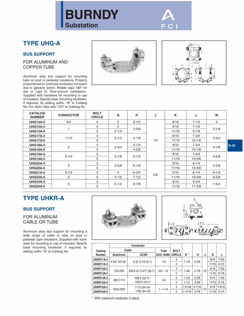
TYPE UHG-A
BUS SUPPORT
FOR ALUMINUM AND COPPER TUBE
Aluminum alloy bus support for mountingtube on post or pedestal insulators. Properlyproportioned to minimize conductor corrosiondue to galvanic action. Rotate caps 180° forslip or rigid fit. One-wrench installation.Supplied with hardware for mounting to capof insulator. Specify base mounting hardware,if required, by adding suffix “-B” to CatalogNo. For static clips add “-CH” to Catalog No.
TYPE UHKR-A
BUS SUPPORT
FOR ALUMINUM CABLE OR TUBE
Aluminum alloy bus support for mounting awide range of cable or tube on post orpedestal type insulators. Supplied with hard-ware for mounting to cap of insulator. Specifybase mounting hardware, if required, byadding suffix “-B” to Catalog No.
* With maximum conductor in place.
CATALOGNUMBER
CONDUCTORBOLT
CIRCLEG H J K L W
UHG14A-3 3/4 3 2 3-1/2
1/2
9/16 7-1/2 3
UHG15A-31
3 23-5/8
9/16 7-1/23-1/8
UHG15A-5 5 2-1/4 11/16 9-7/8
UHG17A-31-1/2
32-1/2 4-1/8
9/16 7-3/43-3/4
UHG17A-5 5 11/16 10-1/8
UHG18A-32
32-3/4
5-1/4 9/16 7-3/44-1/8
UHG18A-5 5 4-5/8 11/16 10-1/8
UHG19A-32-1/2
33-1/8 5-1/4
9/16 7-3/44-5/8
UHG19A-5 5 11/16 10-5/8
UHG20A-33
33-5/8 6-1/8
5/8
9/16 8-1/45-5/8
UHG20A-5 5 11/16 10-5/8
UHG21A-3 3-1/2 3 4 6-3/4 9/16 8-1/4 6-1/4
UHG22A-5 4 5 4-1/2 7-1/2 11/16 10-5/8 6-5/8
UHG24A-35
35-1/4 8-7/8
9/16 8-3/47-3/4
UHG24A-5 5 11/16 11-5/8
CatalogNumber
Conductor
BOLTCIRCLE G * H J K L
Cable TubeSCH. 40/80Aluminum ACSR
UHKR11A-34 Sol.-4/0 Str. 6 (6-1)-4/0 (6-1) 1/4
31-1/8 2-5/8
1/2
9/16 7-5/8
UHKR11A-5 5 11/16 9-1/2
UHKR13A-3250-550 266.8 (6-7)-477 (30-7) 3/8 - 1/2
31-3/8 2-7/8
9/16 7-5/8
UHKR13A-5 5 11/16 8-7/8
UHKR14A-3600-1113
556.5 (26-7) -1033.5 (54-7)
3/43 1-3/4 3-5/8 9/16 7-5/8
UHKR14A-5 5 1-1/2 3-3/8 11/16 9-1/8
UHKR16A-31000-2000
1113 (54-19)-1780 (84-19)
1 - 1-1/43 1-31/32 4-1/16
1/29/16 7-9/16
UHKR16A-5 5 1-13/16 3-7/8 11/16 9-1/4

BURNDYSubstation
G-34
TYPE LB-A
END CAP
Aluminum alloy end cap for aluminum tube.Driven into place for a secure fit. Seals outmoisture, reduces electrostatic loss and elim-inates hazards created by nesting birds.
ROTCUDNOCMUNIMULAEZISEPIP
)]mm[\(NISNOISNEMIDREBMUNGOLATAC
A C L04DHCS 08DHCS
"2/148.]12[
83.]7.9[
52.1]23[
A31BL A35BL
"4/350.1]72[
05.]31[
73.1]53[
A41BL A45BL
"123.1]43[
05.]31[
34.1]63[
A51BL A55BL
"4/1-166.1]24[
05.]31[
34.1]63[
A61BL A65BL
"2/1-109.1]84[
05.]31[
54.1]73[
A71BL A75BL
"283.2]06[
88.]22[
58.1]74[
A81BL A85BL
"2/1-288.2]37[
88.]22[
10.2]15[
A91BL A95BL
"305.3]98[
88.]22[
01.2]35[
A02BL A09BL
"2/1-300.4]201[
88.]22[
51.2]55[
A12BL A19BL
"405.4]411[
88.]22[
22.2]65[
A22BL A29BL
"565.5]141[
88.]22[
43.2]95[
A42BL A49BL
"636.6]861[
88.]22[
64.2]26[
A68BL A69BL
NOTES:1. Material: Cast Aluminum Alloy.2. Dimensions in brackets [ ] are in millimeters.

BURNDYSubstation
G-35
TYPE WAS-A
TERMINAL CONNECTOR
Aluminum alloy weld type terminal for joiningaluminum tube to copper or aluminum pads.Drilling in pad conforms to NEMA standards.PENETROX® joint compound recommendedon pad contact surfaces.
NOTES:1. Material: Cast Aluminum Alloy.2. WELDING TO BE DONE BY THE CUSTOMER. For welding recommendation
see drawing SD736083. After welding, scratch brush connector contact surface dry then apply an oxide
inhibitor “PENETROX® A”.
“PENETROX® A” can be purchased from BURNDY Corporation in cans or plasticsqueeze bottles.
4. Dimensions in brackets [ ] are in millimeters.5. Tongue finished on ONE SIDE ONLY (bottom). For tongue finished on both sides,
add suffix letter "Q" to Catalog No. (e.g., WAS22A-44NQ).
CONDUCTORALUMINUM CATALOG
NUMBERFIG.NO.
DIMENSIONS IN/[MM]
B G L TSCH40/SCH80 A
3/4" 1.05[27] WAS14A-2N 1 2.50
[64]1.50[38]
6.50[165]
.38[9.7]
1"1.32[34]
WAS15A-2N 12.75[70]
1.19[30]
6.75[171]
.38[9.7]
WAS15A-34N 22.75[70]
1.19[30]
6.75[171]
.38[9.7]
1-1/4"1.66[42]
WAS16A-2N 13.00[76]
1.38[35]
7.00[178]
.38[9.7]
WAS16A-34N 2 3.00[76]
1.381.19
7.00[178]
.38[9.7]
1-1/2"1.90[48]
WAS17A-2N 13.25[83]
1.50[38]
7.25[184]
.44[11]
WAS17A-34N 2 3.25[83]
1.50[38]
7.25[184]
.38[9.7]
2"2.38[60]
WAS18A-2N 13.50[89]
1.75[44]
7.50[19]
.44[11]
WAS18A-34N 23.50[89]
1.75[44]
7.50[19]
.38[10]
WAS18A-44N 3 3.63[92]
1.75[44]
8.62[219]
.50[13]
2-1/2" 2.88[73]
WAS19A-2N 1 3.63[92]
2.00[51]
7.87[200]
.56[14]
WAS19A-34N 2 3.63[92]
2.00[51]
7.87[200]
.56[14]
WAS19A-44N 3 3.63[92]
2.00[51]
8.87[225]
.50 [13]
3" 3.50[89]
WAS20A-2N 13.67[93]
2.38[60]
8.25 [21]
.69[18]
WAS20A-34N 2 3.75[95]
2.38[60]
8.25 [21]
.62[16]
WAS20A-44N 3 3.75[95]
2.38[60]
9.25[235]
.62[16]
3-1/2"4.00[102]
WAS21A-34N 2 4.25[108]
2.62[67]
8.50[216]
.62[16]
WAS21A-44N 3 4.25[108]
2.62[67]
9.50[241]
.62[16]
4"4.50[114] WAS22A-44N 3
4.25[108]
2.88[73]
9.50[241]
.75[19]
5"5.56[141] WAS24A-44N 3 4.25
[108]3.62[92]
9.50[241]
.75[19]
6"6.63[168] WAS86A-44N 3
4.25[108]
4.00[102]
9.75[248]
1.00[25]
BURNDYSubstation
G-36
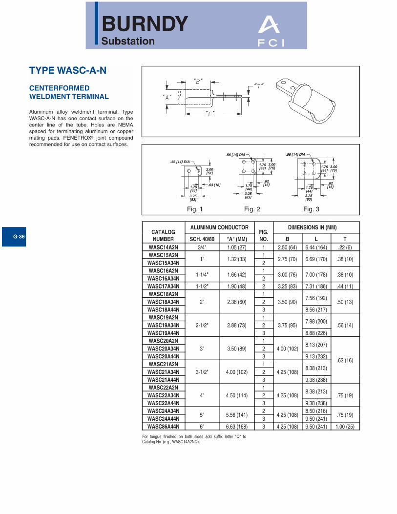
TYPE WASC-A-N
CENTERFORMED WELDMENT TERMINAL
Aluminum alloy weldment terminal. TypeWASC-A-N has one contact surface on thecenter line of the tube. Holes are NEMAspaced for terminating aluminum or coppermating pads. PENETROX® joint compoundrecommended for use on contact surfaces.
For tongue finished on both sides add suffix letter "Q" toCatalog No. (e.g., WASC14A2NQ).
CATALOGNUMBER
ALUMINUM CONDUCTORFIG.NO.
DIMENSIONS IN (MM)
SCH. 40/80 "A" (MM) B L TWASC14A2N 3/4" 1.05 (27) 1 2.50 (64) 6.44 (164) .22 (6)WASC15A2N
1" 1.32 (33)1
2.75 (70) 6.69 (170) .38 (10)WASC15A34N 2WASC16A2N
1-1/4" 1.66 (42)1
3.00 (76) 7.00 (178) .38 (10)WASC16A34N 2WASC17A34N 1-1/2" 1.90 (48) 2 3.25 (83) 7.31 (186) .44 (11)WASC18A2N
2" 2.38 (60)1
3.50 (90)7.56 (192)
.50 (13)WASC18A34N 2WASC18A44N 3 8.56 (217)WASC19A2N
2-1/2" 2.88 (73)1
3.75 (95)7.88 (200)
.56 (14)WASC19A34N 2WASC19A44N 3 8.88 (226)WASC20A2N
3" 3.50 (89)1
4.00 (102)8.13 (207)
.62 (16)
WASC20A34N 2WASC20A44N 3 9.13 (232)WASC21A2N
3-1/2" 4.00 (102)1
4.25 (108)8.38 (213)
WASC21A34N 2WASC21A44N 3 9.38 (238)WASC22A2N
4" 4.50 (114)1
4.25 (108)8.38 (213)
.75 (19)WASC22A34N 2WASC22A44N 3 9.38 (238)WASC24A34N
5" 5.56 (141)2
4.25 (108)8.50 (216)
.75 (19)WASC24A44N 3 9.50 (241)WASC86A44N 6" 6.63 (168) 3 4.25 (108) 9.50 (241) 1.00 (25)
3.25[83]
.63 [16]1.75[44]
.56 [14] DIA
2.00[51]
.56 [14] DIA
1.75[44]3.25[83]
.62[16]
1.75[44]
3.00[76] 1.75
[44]3.00[76]
.56 [14] DIA
1.75[44]3.25[83]
.62[16]
Fig. 1 Fig. 2 Fig. 3

BURNDYSubstation
G-37
"A" DIA.
6.00[152]
Y
1.50 DIA. [38]
.75 DIA.[19]
W
B
TYPE WGA
WELDMENT GROUND STUD
Dimensions in brackets [ ] are in millimeters
DIMENSIONS IN/[mm]CATALOG NUMBER ALUM IPS A B W Y
1.315 - 2.88 3.00 1.32 8.19WG19A 1� - 2-1/2�
[33] - [73] [76] [34] [208]3.50 - 6.62 2.00 3.06 10.31
WG86A 3� - 6�[89] - [168] [51] [78] [262]

Did you know...that in addition to 135 field personnel, FCI BURNDY Products hasover 900 factory and office employees located in New Hampshire,Wisconsin and Connecticut?
“Most people don’t give electrical connectors a second thought. However, they are theheart of any electrical system. FCI has the best connection for your Electrical System.”
Dave HamiltonSr. Product Manager
Did you know...that FCI BURNDY Products has over 45 customer service, pricinganalyst and technical service representatives at headquarters whoanswer the phone by the second ring to respond to your mostdifficult connection questions?
“When selecting a Connector System, I prefer FCI BURNDY Products for qualityand excellent service during and after the sale.”
Mike CarterProject DirectorHumphrey & Associates