Embed Size (px)
Citation preview

Section 6 – Ref. #4
Table of Contents Section Page 1. SCOPE…………………………………………………………………………… 1
1.1 Toronto Hydro Requirements……………………………………………… 1 1.2 Enclosed Switchgear……………………………………………………….. 1 1.3 Ontario Electrical Safety Code…………………………………………….. 1 1.4 SI Units…………………………………………………………………….. 1
2. PURPOSE………………………………………………………………………. 1 3. DEFINITIONS…………………………………………………………………. 2 4. EXTENT OF TORONTO HYDRO JURISDICTION………………………. 3
4.1 Point of Entry to Protective Devices……………………………………… 3 4.2 Jurisdiction Coverage Extension………………………………………….. 3
5. METHOD OF SUPPLY………………………………………………………. 4
5.1 Number of Feeders………………………………………………………... 4 5.1.1 One-Feeder Supply……………………………………………….. 4 5.1.2 Two-Feeder Supply………………………………….……………. 4 5.1.3 Three or More Feeder Supply…………………………………….. 4
5.2 Automatic Load Transfer………………………………………………….. 4 5.3 Feeder Termination……………………………………………………….. 5 5.4 Duplicate Metering……………………………………………………….. 5
6. PROCEDURE FOR OBTAINING TORONTO HYDRO APPROVAL……. 5
6.1 Drawings…………………………………………………………………… 5 6.2 Additional Drawings………………………………………………………. 5 6.3 Manufacture of Equipment – Drawing Approval…………………………. 5 6.4 Inspection of Equipment Prior to Shipment……………………………….. 5 6.5 Compliance with Requirements……………………………………………. 5 6.6 Additional Dielectric Strength Tests..……………………………………… 6 6.7 Dual Locks…….…………………………………………………………… 6 6.8 Automatic Transfer Relay Settings…………………………………………. 6 6.9 Pre-Service Inspection Report and Final Connection……………………… 6 6.9.1 As Constructed Drawings ……………………………………………. 6 6.9.2 Transformer and Cable Tests Requirements …………………………. 6 6.9.2.1 Transformer Test Requirements ……………………………… 6 6.9.2.2 High Voltage Cable Test Requirements ……………………… 7
7. DRAWINGS AND INFORMATION REQUIRED FOR APPROVAL……… 7 7.1 Substation Drawings………………………………………………………… 7 7.2 Single Line Diagram………………………………………………………… 8 7.3 Specifications of Electrical Equipment……………………………………… 8 7.4 Switchgear Assembly Drawings…………………………………………….. 8 7.5 Schematic and Connection Wiring Diagrams……………………………….. 8 7.6 Protection Co-ordination Study……………………………………………… 9
Section 6 – Ref. #4
7.7 Final Documents.…………………………………………………………….. 9 8. SUBSTATION REQUIREMENTS……………………………………………… 9
8.1 General Requirements……………………………..………………………… 9 8.2 Exits and Doors……………………………………………………………… 9
8.2.1 Mean of Egress and Exit Door Requirements………………………. 9 8.2.2 Legislation and Specific Requirements……………………………… 9
8.3 Cable Pulling………………………………………………………………… 10 8.4 Cable Racks and Conduits…………………………………………………… 11 8.5 Outdoor Substations – Fence and Gates……………………………………… 11 8.6 Safe Working Space…………………………………………………………. 12
8.6.1 Working Space About Equipment…………………………………… 12 8.6.2 Minimum Space Requirement……………………………………….. 12 8.6.3 Side or Rear Access Panels………………………………………….. 12 8.6.4 Aisle Space………………………………………………………….. 12 8.6.5 Blocking of Exit Route……………………………………………… 13 8.6.6 Illumination of Equipment…………………………………………… 13 8.6.7 Accessibility for Maintenance……………………………………… 13
8.7 Access to Substation by Toronto Hydro…………………………………….. 13 8.8 Communication Lines……………………………………………………….. 13 8.9 SF6 Switchgear……………………………………………………………… 13 8.10 Power Supply………………………………………………………………… 13 8.11 Single Line Diagram ………………………………………………………… 14
9. EQUIPMENT REQUIREMENTS……………………………………………… 14
9.1 System Parameters/Ratings………………………………………………… 14 9.2 Enclosures…………………………………………………………………… 14
9.2.1 Sheet Steel Enclosures……………………………………………… 14 9.2.2 Electro-magnetic Effects…………………………………………… 14 9.2.3 Design of Enclosures………………………………………………… 15 9.2.4 Ventilation…………………………………………………………… 15 9.2.5 Enclosure Interiors…………………………………………………… 15 9.2.6 Mimic Bus …….………………………………………………….… 15 9.2.7 Name Plates…………………………………………………………. 15
9.3 Compartmentation…………………………………………………………… 15 9.3.1 Separate Compartments……………………………………………… 15 9.3.2 Compartment and Openings………………………………………… 16 9.3.3 Intercompartmental Primary Connections…………………………… 16 9.3.4 Exceptions…………………………………………………………… 16
9.4 Access Doors………………………………………………………………… 17 9.4.1 Doors for Compartments…………………………………………… 17 9.4.2 Hinged Access Doors……………………………………………….. 17 9.4.3 Padlock Hasps…………………………………………………….… 17 9.4.4 Securing Access Doors………………………………………….…… 17 9.4.5 Stops on Access Doors………………………………………….…… 18
9.5 Screen Doors………………………………………………………………… 18 9.5.1 Single Access Doors………………………………………………… 18 9.5.2 Screen Approval…………………………………………………….. 18

Section 6 – Ref. #4
9.6 Viewing Windows……………………………………………………………. 18 9.7 Toronto Hydro Incoming Feeder Terminations……………………………… 19
9.7.1 Types of Cables and Terminations……………………………….…... 19 9.7.2 Scope of Materials Supply……………………………………….…… 19 9.7.3 Bottom Entry Cables…………………………………………………. 20 9.7.4 Top Entry Cables…………………………………………………….. 20
9.8 Barriers……………………………………………………………………….. 20 9.8.1 Requirement for Barriers……………………………………………… 20 9.8.2 Horizontal Barriers……………………………………………………. 21 9.8.3 Type of Barriers………………………………………………………. 21
9.9 Lightning Arresters…………………………………………………………… 21 9.10 Voltage Indicators…………………………………………………………….. 21 9.11 Circuit Breaker………………………………………………………………... 21 9.12 Control Power Supply………………………………………………………… 22 9.13 Power Fuses…………………………………………………………………… 22
9.13.1 Minimum Rating……………………………………………………… 22 9.13.2 Gas Expelling Type…………………………………………………… 22
9.14 Loadbreak Switches………………………………………………………….. 22 9.14.1 Minimum Ratings…………………………………………………….. 22 9.14.2 Type of Switch……………………………………………………….. 22 9.14.3 Operating Mechanism………………………………………………… 23 9.14.4 Switch Contacts………………………………………………………. 23 9.14.5 Operating Warning Sign …………………………………………….. 23
9.15 Isolating Switches…………………………………………….……………… 23 9.15.1 Location of Switches………………………………………………… 23 9.15.2 Switch Requirement………………………………….……………… 23 9.15.3 Isolation for Vacuum Type Circuit Breakers or Switches…………… 23
9.16 Electrical Clearances………………………………..……………………….. 24 9.16.1 Bare Conductors…………………………………………………….. 24 9.16.2 Connection Clearances……………………………………………… 24
9.17 Interlocks………………………………..………………………………….. 24 9.17.1 Incoming Circuit Breakers or Loadbreak Switches………………… 24 9.17.2 Incoming Isolating Switch …………………………………………. 24 9.17.3 Access Door of Power Fuse Compartment………………………… 24 9.17.4 Loadbreak Switch on Outgoing Circuit…………………………….. 25 9.17.5 Circuit Breaker on Outgoing Circuit……………………………….. 25 9.17.6 Incoming Circuit Breaker and Isolating Switch……………………. 25 9.17.7 Customer Service Loadbreak Switch………………………………. 25 9.17.8 Marking of Interlock Keys…………………………………………. 25
9.18 Grounding………………………………..………………………………… 25 9.18.1 Additional Grounding…………..………………………………….. 25 9.18.2 Grounding Facilities ……………………………………………….. 25 9.18.3 Cable Compartment………………………………………………… 26 9.18.4 Voltage Transformer Compartment………………………………… 26 9.18.5 Metallic Parts………………………………………………………. 26 9.18.6 Ground Grid Connections………………………………………….. 26
9.19 Automatic Transfer between Normal and Standby Supply………………… 26 9.19.1 Notification Requirements………………………………………….. 26 9.19.2 Automatic Transfer Functional Requirements………………………. 26

Section 6 – Ref. #4
9.20 Emergency Backup and Embedded Generation…………………………….. 28 9.20.1 Emergency Backup Generation……………………………………… 28 9.20.2 Embedded Generation………………..……………………………… 28
9.21 Pilot Wire Protection and Remote Tripping………………………………… 29 9.21.1 Interstation Control Cables Cabinet…………………………………. 29 9.21.2 Remote Tripping Relays……………………………………………. 29
9.22 Test Blocks……….………………………………………………………… 29 9.23 Annunication-SF6 Low Pressure…………………………………………… 29 9.24 Protective Relays…………………………………………………………… 30
9.24.1 Relay Settings………………………………………………………. 30 9.24.2 Current Transformer Secondary Wiring…………………………… 30
10. METERING REQUIREMENTS………………………………………………. 30 11. ASSOCIATED PUBLICATIONS……………………………………………… 31 SKETCHES…………………………………………………………………………. 32
Requirements for the Design & Construction of Customer-Owned High-Voltage Substations
Section 6 – Ref. #4 Page 1
1. SCOPE
1.1 Toronto Hydro Requirements
This publication covers the design, construction, substation layout and the electrical equipment located in customer-owned high voltage substations. Any exceptions to this publication shall be brought to the attention of Toronto Hydro in writing at the drawing approval stage. The requirements are in addition to the latest edition of:
a) The requirements for the "Supply Authority" as covered in the Ontario Electrical
Safety Code; b) The "Conditions of Service" published by Toronto Hydro; c) The “THESL Requirements for Customer-Owned Structures” d) The “Toronto Hydro General Requirements for Parallel Generation” in the
Conditions of Service; e) The “Toronto Hydro Metering Requirements for 13.8kV & 27.6kV Customer-
Owned Substations”; f) Associated Publications in section 11.
1.2 Enclosed Switchgear
These requirements cover metal enclosed (indoor or outdoor) switchgear. Open type switchgear may be acceptable if appropriate protective and gang-operated isolating device(s) is installed between the Customer facility and Toronto Hydro system. Additional conditions on metering may be required for open-type switchgear.
1.3 Ontario Electrical Safety Code and Ontario Building Code
Unless exceptions are granted by the governing Authorities, nothing contained in these requirements shall prejudice or supersede any regulations or requirements of the Ontario Electrical Safety Code and Ontario Building Code.
1.4 SI Units
All dimensions and weights are stated in metric units. Equivalent measurements will be accepted if equipment or materials are not manufactured in metric units.
2. PURPOSE
These requirements are intended to provide guidance to Toronto Hydro Customers in designing and constructing 13.8kV or 27.6kV Customer-Owned Substations for the purpose of: (a) Assuring safe conditions for Customer and Toronto Hydro personnel in operating and
maintaining Customer-Owned Substations.
(b) Assuring a continuity of supply to all customers by the use of adequate specifications and proper design factors.
Requirements for the Design & Construction of Customer-Owned High-Voltage Substations
Section 6 – Ref. #4 Page 2
3. DEFINITIONS
Acceptable Meets Toronto Hydro requirements.
Approval Approval of drawings and customers’ equipment is limited to Toronto Hydro’s requirements and does not construe as acceptance of liability arising from faulty design or workmanship.
Compartment A subdivision of a unit.
Customer Means a person that has contracted for or intends to contract for connection of a building or an embedded generation facility. This includes developers of residential or commercial sub.
Customer-owned Substation
A customer-owned civil structure accommodating customer-owned electrical equipment connected to Toronto Hydro 13.8kV or 27.6kV system.
Embedded Generation Facility
Means a generation facility which is not directly connected to the IMO-controlled grid but instead is connected to a distribution system.
Embedded Generator A generator whose generation facility is not directly connected to the IMO-controlled grid but instead is connected to a distribution system.
Emergency Backup Generation Facility
Means a generation facility that has a transfer switch that isolates it from a distribution system.
Exit A path of travel which leads from a floor area to a separate building, an open public thoroughfare or an exterior open space which is protected from fire exposure from the building and has access to an open public thoroughfare.
High Voltage In this document context, high voltage means 13.8kV or 27.6kV.
IMO Independent Electricity Market Operator
Means of Egress A means of egress is a continuous path of travel provided for the escape of persons from any point in a building or contained open space (i.e. Substation) to an open public thoroughfare. The means of egress includes the exit and the access to the exit.
MSG Manufacturer’s Standard Gauge for uncoated steel.
Sprinkler-Proof Enclosure
An enclosure for indoor application so constructed or protected that water from sprinkler systems will not interfere with the successful operation of the enclosed switchgear, excluding flooding.

Requirements for the Design & Construction of Customer-Owned High-Voltage Substations
Section 6 – Ref. #4 Page 3
Switchboard Switchboard means a switchgear assembly that consists of one or more panels upon which are mounted switching control, meters and protective regulatory equipment and in which the panel or panel supports may also carry the main switching and interrupting devices together with their connections.
Unit (Switchgear) A full height and full depth module of a switchgear assembly. It is sometimes referred to as “cell”, “cubicle”, “section” or “enclosure”.
Vault (Transformer) An isolated enclosure with fire-resistant walls, ceiling and floors, for the purpose of housing transformers and other electrical equipment.
4. EXTENT OF TORONTO HYDRO JURISDICTION
4.1 Point of Entry to Protective Devices
For the purpose of these requirements, Toronto Hydro jurisdiction normally covers the equipment between the point of entry of the supply cables into the Customer’s property and the load side of the first protective devices, i.e. fuses or circuit breakers.
4.2 Jurisdiction Coverage Extension
Toronto Hydro jurisdiction is extended beyond the above limits to cover:
(a) Toronto Hydro metering equipment when located on the load side of the first
protective devices.
(b) Protective devices located on the load side of the first protective devices in cases where the first protective devices cannot function as required with the Toronto Hydro feeder protection.
(c) Interlocks intended to prevent paralleling the Toronto Hydro incoming lines when located beyond the area described in 4.1.
(d) Interlocks which prevent the paralleling of an Emergency Backup Generator with the Toronto Hydro Supply.
(e) Any equipment which may affect the safety of Toronto Hydro personnel.
(f) For safety and security reasons, the Customer must obtain approval from Toronto Hydro before operating the incoming load break switches or circuit breakers.

Requirements for the Design & Construction of Customer-Owned High-Voltage Substations
Section 6 – Ref. #4 Page 4
5. METHOD OF SUPPLY The conditions of supply for Customer-Owned Substations are outlined in section 2 of Conditions of Service.
5.1 Number of Feeders
5.1.1 One-Feeder Supply
Typical one-feeder supply arrangements are shown in sketches 1(b) and 1(c).
5.1.2 Two-Feeder Supply Typical two-feeder supply arrangements are shown in sketches 1(d) to 1(h).
With two-feeder supply, the feeders are not permitted to operate in parallel. One feeder (Normal) will normally carry the total customer’s load and the other (Standby) will remain open on potential. Automatic Transfer Switch may be installed to improve reliability (refer to 5.2 and 9.19).
If a split-bus arrangement [sketch 1(h)] is employed, each of the two feeders can carry its own load but the tie-switch (or tie-breaker) must be open to prevent paralleling of the two feeders. In this arrangement, Customer must ensure that the transformer secondaries on either side of the split-bus be electrically separated (not paralleled).
The Customer shall not install any equipment to permit electrical connection between transformer secondaries across the split bus.
5.1.3 Three or More Feeder Supply
When three or more feeders are designed to operate in parallel, circuit breakers and pilot wire relay protection and remote trip receiving relay shall be required [refer to sketch 1(i)]. Pilot wire relay protection arrangement is provided at the sole discretion of Toronto Hydro. Additional conditions and premium costs may apply.
5.2 Automatic Load Transfer (Automatic Transfer Switch).
Subject to Toronto Hydro approval, an automatic load transfer may be employed where the Customer requires a higher degree of service reliability than that afforded by other methods of supply. Each feeder is connected to the Customer’s switchgear through a circuit breaker (or motorized loadbreak switch) one of which is normally closed and carrying load, the other open and on potential. Automatic transfer is initiated on a voltage sensing basis, the voltage sensing being obtained from potential transformers located on the source side of incoming feeder breakers (or motorized loadbreak switch) (Refer to 9.19 for details).
Requirements for the Design & Construction of Customer-Owned High-Voltage Substations
Section 6 – Ref. #4 Page 5
5.3 Feeder Termination
Each feeder shall be terminated in the Customer’s switchgear and shall be connected to the Customer’s bus either through a circuit breaker equipped with a primary disconnecting device or through a loadbreak switch [refer to sketches 1(b) through 1(h)].
5.4 Duplicate Metering
Where a Customer has a two-feeder arrangement [Normal and Standby, Refer to sketch 1(g)] that requires dual metering, the Customer shall be responsible for the additional metering cost.
6. PROCEDURE FOR OBTAINING TORONTO HYDRO APPROVAL
Following acceptance of a Customer’s application for a 13.8kV or 27.6 kV supply or a proposal to modify an existing 13.8kV or 27.6kV substation, the procedure shall be as follows:
6.1 Drawings
The Customer shall submit to Toronto Hydro for approval the drawings and information listed in Section 7.
6.2 Additional Drawings
If the drawings or information do not meet Toronto Hydro requirements or are not sufficiently clear, then revised or additional drawings and information must be submitted on request.
6.3 Manufacture of Equipment – Drawing Approval
Manufacture of equipment should not start until all drawings and information have been approved by Toronto Hydro. This will avoid costly changes to completed equipment. Final revised l drawings must be delivered to Toronto Hydro at least four weeks prior to the delivery of the switchgear to the substation site.
6.4 Inspection of Equipment Prior to Shipment
Toronto Hydro reserves the right to inspect the completed equipment at the manufacturer’s plant prior to shipment.
6.5 Compliance with Requirements
When the installation of the switchgear has been completed, the customer shall utilize a qualified testing agency and subject the switchgear to a Dielectric Strength Test. The voltage applied shall be 75% of the factory test voltage in accordance with clause 8.6.1 of CSA Standard C22.2 No. 31 “Switchgear Assemblies”. Toronto Hydro shall witness

Requirements for the Design & Construction of Customer-Owned High-Voltage Substations
Section 6 – Ref. #4 Page 6
the testing of the switchgear by the qualified testing agency during normal working hours. Notice of witness testing date shall be submitted to Toronto Hydro at least 2 weeks in advance. A test report certified by a Professional Engineer shall be submitted for approval before the energization of switchgear.
6.6 Additional Dielectric Strength Tests
Should the switchgear fail to pass the Dielectric Strength Test, the Customer shall make the necessary modifications and a further dielectric test shall be performed.
6.7 Dual Locks
A u-bolt dual locking facility is required on the operating handle of the incoming switchgear to allow locking in the open or closed position. Either Toronto Hydro or the Customer can open the lock. The Customer must consult Toronto Hydro before any closing operations.
6.8 Automatic Transfer Relay Settings
Where circuit breakers or automatic transfer switches are used, Toronto Hydro personnel shall witness the setup of the relays and the testing of the protection and control devices for correct operation of these devices.
6.9 Pre-Service Inspection Report and Final Connection
A pre-service inspection report shall be submitted to Toronto Hydro for approval prior to final connection of supply to Customer substation. Toronto Hydro reserves the right to carry out additional inspections. A Connection Authorization from the Electrical Safety Authority is also required prior to final supply connection. The pre-service inspection report shall include the following items and shall have a conclusion on whether or not the substation is satisfactory for energization.
6.9.1 As Constructed Drawings
The pre-service inspection contractor shall have a Professional Engineer certify that the customer’s installation was completed in accordance with the original drawings that were approved by Toronto Hydro and return a set of these drawings to Toronto Hydro to keep on file as “As Constructed” drawings. The drawings to be certified must be original, photocopies are not acceptable. Refer to section 7 for drawings and information required for approval.
6.9.2 Transformer and Cable Tests Requirements
The following transformer and cable tests shall be certified by a Professional Engineer:
6.9.2.1 Transformer Test Requirements
- Turns Ratio (all taps) - Insulation Resistance (Mega-Ohms for 60 seconds, indicate test voltage)

Requirements for the Design & Construction of Customer-Owned High-Voltage Substations
Section 6 – Ref. #4 Page 7
6.9.2.2 High Voltage Cable Test Requirements
Test voltage applied as follows: Duration shall be 15 minutes with leakage reported in microamperes at 1-minute intervals.
System Voltage Test Voltage
13.8 kV AC 54 kV DC 27.6 kV AC 86 kV DC
7. DRAWINGS AND INFORMATION REQUIRED FOR APPROVAL
Five copies of each of the drawings and information listed in 7.1 to 7.6 inclusive shall be submitted to Toronto Hydro for the attention of CFDC (Customer Facilities Design & Construction) Department, unless otherwise advised, for approval. Additions and modifications to existing equipment shall be clearly indicated.
All drawings shall be approved and stamped by a Professional Engineer before submission to Toronto Hydro for review.
Drawings shall be fully dimensioned and scaled. Photo-reduced copies of the original and unapproved drawings shall not be accepted.
All dimensions shall be in S.I. units.
7.1 Substation Drawings
Drawings shall indicate: (a) Site Plan: The location of the substation relative to buildings, structures, property
lines, the nearest public thoroughfare, and other equipment in the vicinity of the substation including vehicular and personnel access route.
(b) The proposed route of Toronto Hydro incoming supply cables, including details of primary duct bank.
(c) The location of any pipes or ducts in the vicinity of the substation, e.g. ventilating ducts, water, gas, sewage pipes, sprinkler system, access openings, windows, vehicle access, access direction, etc.
(d) Layout of the equipment in the electrical room clearly indicating aisle clearances and exits.
(e) Details of cable pits, ducts or vaults.
(f) Details of substation grounding arrangements and location of any ground grids used.
(g) Details and location of meter cabinet. Refer to Metering Diagrams #1, #2, #3 and the Conditions of Service.

Requirements for the Design & Construction of Customer-Owned High-Voltage Substations
Section 6 – Ref. #4 Page 8
7.2 Single Line Diagram The following information shall be included in the drawing:
(a) Ratings, impedances and taps of the main transformers.
(b) Ratings and short circuit capabilities of circuit components.
(c) Details of all primary cables e.g. voltage, size, material, etc.
(d) Interlocking arrangements with an explanation of operational sequences.
(e) Proposed protective relaying scheme, where applicable, showing relay types and instrument transformer ratios and accuracy.
7.3 Specifications of Electrical Equipment
These shall include dimensions, ratings, manufacturer, type, and other technical information.
7.4 Switchgear Assembly Drawings
Drawings shall provide the following information:
(a) Plan, elevation and sectional views (front and side) of the switchgear assembly
including working clearances.
(b) Grounding details. (Refer to 9.18.)
(c) Provisions for Toronto Hydro metering equipment. (Refer to Section 10 and the Conditions of Service)
(d) Provisions for access to components. (Refer to 9.4 and 9.5.)
(e) Description of principal components.
(f) Details of barriers (Refer to 9.8.)
(g) Electrical clearances (Refer to 9.16.)
(h) Interior paint finish (Refer to 9.2.5.)
(i) Name plate.
(j) Interlock scheme and dual lock provision.
7.5 Single Line and Schematic Wiring Diagrams
These shall include AC single line and DC schematic drawings and connection wiring diagrams of the protection and control equipment used in conjunction with circuit breakers and motor operated switches. [Refer to sketch 5].

Requirements for the Design & Construction of Customer-Owned High-Voltage Substations
Section 6 – Ref. #4 Page 9
7.6 Protection Co-ordination Study
All customers’ devices associated with the 13.8kV or 27.6kV equipment shall coordinate with Toronto Hydro upstream protection. Toronto Hydro shall provide upstream protection information as required. Customer shall submit a protection coordination study report to Toronto Hydro for approval.
7.7 Final Documents
The Customer shall submit the final documents mentioned above to Toronto Hydro for approval. Failure to provide Toronto Hydro with the final documents may delay the substation connection to the Toronto Hydro supply system.
8. SUBSTATION REQUIREMENTS
8.1 General Requirements
The substation shall be constructed and equipped in accordance with the relevant standards, governmental codes and regulations.
The substation shall be located on the ground level. If a suitable ground level location is not available, Toronto Hydro may accept a below-grade location, provided the location is immediately one floor below the ground level.
8.2 Exits and Doors
8.2.1 Means of Egress and Exit Door Requirements Two separate means of egress each with an Exit door and located at opposite side of the substation area are required. Each means of egress shall allow a separate escape route to exit from any point in the substation area to an open public thoroughfare.
The doors shall be fitted with a keyed cylinder lock and installed on the opposite side of the panic type bar, all to be acceptable to Toronto Hydro.
Each exit door shall be equipped with an EXIT sign.
Entrance and exit doors must remain clear of obstructions at all times.
8.2.2 Legislation and Specific Requirements The exits shall conform to the latest revision of the Ontario Building Code and “The Ontario Occupational Health and Safety Act, and Regulation for Industrial Establishments – Part II – Buildings” from which the following are extracted:
(a) OHSA Rules 122 states that:
(1) This section applies with respect to a hazardous room,
(a) With an area greater than fifteen square meters; or

Requirements for the Design & Construction of Customer-Owned High-Voltage Substations
Section 6 – Ref. #4 Page 10
(b) Requiring a distance of travel greater than 4.5 m from any point in the room to an egress doorway.
(2) A hazardous room shall be located in a floor area that has at least two exits.
(3) A hazardous room shall have at least two egress doorways that are at least three-quarters of the length of the diagonal distance of the room from each other.
(4) One egress doorway must be located within a maximum distance of twenty-three meters from any point in a hazardous room.”
(b) If doors are used they shall open in the direction of exit travel and swing on their vertical axes. [Direction of Door Swing – Ontario Building Code, latest edition].
(c) The door(s) must open readily from inside the room at all times it is occupied. Locks shall not require a key to operate from inside.
(d) Where more than one door is employed, all doors shall be equipped with panic hardware.
(e) Doors equipped with panic hardware must open under 90N releasing pressure applied in the direction of exit travel. [Door Release Hardware – Ontario Building Code, latest edition]
(f) Panic hardware must be located between 0.76 m and 1.12 m above floor level on room doors.
Note: Where double doors are used; only one of the pair requires panic hardware.
(g) Where the exit doors open into an area where the means of egress may be impeded by vehicular traffic, protective removable bollards shall be installed by the customer.
(h) Cable Pull Room Doors – Class B (3/4 hr) fire doors or better shall be supplied and installed by the customer. For cable installations over 750V – “High Voltage” warning signs shall be installed on the door. The fire doors and frames, ventilating shafts or louvered windows for ventilation are to be grounded.
8.3 Cable Pulling
Cable pulling loops or eyes shall be installed by the Customer opposite the incoming duct faces in Customer’s electrical room, pull room or cable chamber. In addition, the following shall be adhered to:
(a) Where the service entrance must be in such a location that underground cables
cannot be pulled directly into the electrical room, the customer shall provide an acceptable cable pull room, or cable chamber to be used as an intermediate pull location. [Refer to the Toronto Hydro Requirements for Customer-Owned

Requirements for the Design & Construction of Customer-Owned High-Voltage Substations
Section 6 – Ref. #4 Page 11
Structures (Toronto Hydro Standards 31-6000, 31-6010, 31-6020, 31-6030, 31-6040, 31-6050, 31-6060 and 31-6080)].
(b) Clearance for pulling cable – In all circumstances, space must be available for a
straight cable pull between the duct face and the pulling loop or eye. Where there is less than 3.0 m clear space from the duct face to the pulling loop or eye, every effort should be made to locate the room door in the wall opposite the duct face. If a door is not practical, an opening close to the floor level and with a removable cover should be provided in the wall containing the pulling loop or eye.
8.4 Cable Racks and Conduits
(a) Where required, cable supports, racks, and mechanical protection shall be
supplied and installed at the customer’s expense.
Conduit installations on Customer’s premises for Toronto Hydro incoming cables shall conform to Toronto Hydro’s standard practices. [Refer to the Toronto Hydro Requirements for Customer-Owned Structures (Toronto Hydro Standards 31-6000, 31-6010, 31-6020, 31-6030, 31-6040, 31-6050, 31-6060 and 31-6080)].
(b) The maximum length of the cable from the duct face to the customer owned switchgear shall not exceed 7.5 m. The installation shall meet the requirement of Ontario Electrical Safety Code rule 36-100.
8.5 Outdoor Substations – Fence and Gates
(a) Guarding of Electrical Equipment
All outdoor substations shall be surrounded by guarding fence and gates in accordance with OESC rule 26-302 to 26-324 and section 8.6.
(b) Height of Fence
The fence, excluding barbed wire, shall not be less than - 1.8m high.
(c) Barbed Wire
The fence shall be topped with not less than three strands of barbed wire.
(d) Gates
(i) Gates shall preferably open outwardly but, if it is necessary that they open inwardly, they shall not come into contact with the frame or enclosure of any electrical equipment when fully opened; a clear passageway at least 0.9 m wide and 2.2 m high shall be maintained to ensure safe egress.
(ii) Double gates with center stops shall be used where the width of opening exceeds 1.5 m.
(iii) All gates shall have security provision for accepting both Customer and Toronto Hydro padlocks; also, “High-Voltage Warning” signs shall be affixed to them.

Requirements for the Design & Construction of Customer-Owned High-Voltage Substations
Section 6 – Ref. #4 Page 12
(e) Grounding Substation grounding shall meet the requirements of Ontario Electrical Safety Code, 36-300 to 36-312.
8.6 Safe Working Space
Safe working space in vicinity of service entrance equipment including metering shall be in accordance with the Ontario Electrical Safety Code Rule 2-308 and shall include the following: 8.6.1 Working Space About Equipment
(a) A minimum working space of 1.0 m with secure footing shall be provided and maintained about electrical equipment such as switchboards, panel boards, control panels and motor control centres which are enclosed in metal, except that working space is not required behind such equipment where there are no renewable parts such as fuses or switches on the back and where all connections are accessible from locations other than the back. (Also refer to 8.6.2 for Toronto Hydro clearances.)
(b) The space referred to in 8.6.1(a) shall be in addition to the space required for the operation of draw-out type equipment in either the connected, test, or fully disconnected position and shall be sufficient for the opening of enclosure doors and hinged panels to at least 90º.
(c) Working space with secure footing not less than that specified in Table 56 of Ontario Electrical Safety Code – Minimum Working Space About Electrical Equipment Having Exposed Live Parts, shall be provided and maintained about electrical equipment such as switchboards, control panels and motor control centres having exposed live parts.
(d) The minimum headroom of working space about switchboards or motor control centres where bare live parts are exposed at any time shall be 2.2m.
8.6.2 Minimum Space Requirement
A minimum of 1.5 m. shall be provided in front of all doors giving access to switchgear components and where Toronto Hydro is required to work.
8.6.3 Side or Rear Access Panels Where removable side or rear access panels are required, a minimum working space of 0.9 meter with 2.2 m clear headroom shall be maintained.
8.6.4 Aisle Space
A clear passageway at least 0.9 m wide and 2.2 m high shall be maintained as an exit route from all service entrance equipment. This headroom must also be maintained in the working space in the vicinity of the service entrance equipment.
Requirements for the Design & Construction of Customer-Owned High-Voltage Substations
Section 6 – Ref. #4 Page 13
8.6.5 Blocking of Exit Route Where the compartment hinged doors or drawout components would block the exit route then a clear minimum space of 0.6 m must be maintained from the edge of the access door or components in the fully open position.
8.6.6 Illumination of Equipment
Adequate illumination shall be provided to allow for proper operation and maintenance of electrical equipment in accordance with Ontario Electrical Safety Code Rule 2-314. The lighting shall be controlled by wall switches located at the entrances to these areas.
8.6.7 Accessibility for Maintenance
Passageways and working space around electrical equipment shall not be used for storage and shall be kept clear of obstruction and so arranged as to give authorized persons ready access to all parts requiring attention in accordance with Ontario Electrical Safety Code Rule 2-312.
8.7 Access to Substation by Toronto Hydro
Immediate access to the substation must be provided on a 24-hour basis for Toronto Hydro personnel. A door equipped with a Toronto Hydro lock, giving direct access to the substation from the outside (e.g. street) shall be provided where practicable. Alternatively the doors along the route leading to the substation must be equipped with Toronto Hydro locks.
If Toronto Hydro locks are not practical, the customer shall provide Toronto Hydro the appropriate access keys or magnetic cards to enable entry from outside (e.g. street) to the substation. Toronto Hydro shall supply and install a key box at a suitable location to safekeep the key(s).
8.8 Communication Lines
Where the customer’s electrical room is located such that radio communication with the Toronto Hydro Control Centre is not adequate; the customer shall provide a telephone in the electrical room.
8.9 SF6 Switchgear
Where SF6 switchgear is installed inside the substation, a means of annunciation of low SF6 gas pressure shall be provided to the outside of the substation. This annunciation shall consist of an external warning light installed above each access entrance. A sign stating “Low SF6 Gas Pressure” shall be mounted above the external warning light. A “Lamp Test” button shall be installed on the external annunciation unit for means of testing the warning light before entering the substation. [Refer to 9.23(e)]
8.10 Power Supply
A 120V a.c. 15-ampere 2-pole 3-wire grounded receptacle shall be provided close to Toronto Hydro’s incoming feeder compartment. If installed outdoors, the receptacle shall be weatherproof and protected by a ground fault circuit interrupter of the Class A type.
Requirements for the Design & Construction of Customer-Owned High-Voltage Substations
Section 6 – Ref. #4 Page 14
8.11 Single Line Diagram The Customer shall provide and post a mounted single line diagram (latest revision) of good quality print on a wall in the electrical room for reference. The Customer shall also update the single line diagram to include those switching equipment designations that may be assigned from time to time by Toronto Hydro.
9. EQUIPMENT REQUIREMENTS
9.1 System Parameters/Ratings
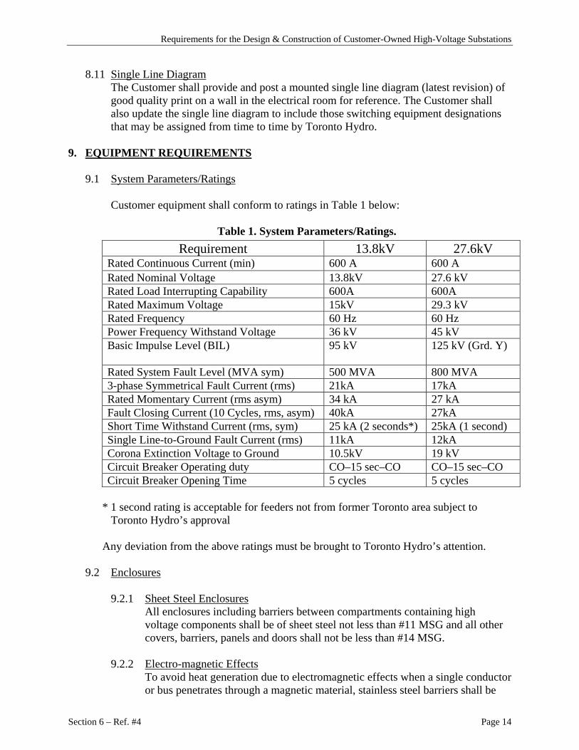
Customer equipment shall conform to ratings in Table 1 below:
Table 1. System Parameters/Ratings. Requirement 13.8kV 27.6kV
Rated Continuous Current (min) 600 A 600 A Rated Nominal Voltage 13.8kV 27.6 kV Rated Load Interrupting Capability 600A 600A Rated Maximum Voltage 15kV 29.3 kV Rated Frequency 60 Hz 60 Hz Power Frequency Withstand Voltage 36 kV 45 kV Basic Impulse Level (BIL) 95 kV 125 kV (Grd. Y)
Rated System Fault Level (MVA sym) 500 MVA 800 MVA 3-phase Symmetrical Fault Current (rms) 21kA 17kA Rated Momentary Current (rms asym) 34 kA 27 kA Fault Closing Current (10 Cycles, rms, asym) 40kA 27kA Short Time Withstand Current (rms, sym) 25 kA (2 seconds*) 25kA (1 second) Single Line-to-Ground Fault Current (rms) 11kA 12kA Corona Extinction Voltage to Ground 10.5kV 19 kV Circuit Breaker Operating duty CO–15 sec–CO CO–15 sec–CO Circuit Breaker Opening Time 5 cycles 5 cycles
* 1 second rating is acceptable for feeders not from former Toronto area subject to
Toronto Hydro’s approval Any deviation from the above ratings must be brought to Toronto Hydro’s attention.
9.2 Enclosures
9.2.1 Sheet Steel Enclosures
All enclosures including barriers between compartments containing high voltage components shall be of sheet steel not less than #11 MSG and all other covers, barriers, panels and doors shall not be less than #14 MSG.
9.2.2 Electro-magnetic Effects
To avoid heat generation due to electromagnetic effects when a single conductor or bus penetrates through a magnetic material, stainless steel barriers shall be

Requirements for the Design & Construction of Customer-Owned High-Voltage Substations
Section 6 – Ref. #4 Page 15
used. Aluminum barriers are not acceptable. Also, refer to Section 9.7.2 (c) (ii) for requirements on strain relief connectors.
9.2.3 Design of Enclosures
The switchgear enclosure shall be designed in accordance with the rules of the Canadian Electrical Code, Part I and as defined in latest CAN/CSA Standard C22.2 No. 94. Heaters shall be used in the switchgear and shall be controlled by humidistat.
9.2.4 Ventilation
Ventilating openings, if required, shall be designed to prevent the entrance into the enclosure of any object, which could come into hazardous proximity to live parts.
9.2.5 Enclosure Interiors
Interiors of enclosures shall be finished in white enamel.
9.2.6 Mimic Bus A mimic bus on front door of switchgear compartment with no rear access shall indicate the internal electrical arrangement of equipment in each compartment. The mimic bus shall be securely fastened to the panel. For switchgear with rear access, all components, both front and rear, shall be marked and labeled similarly.
9.2.7 Name Plates
Switchgear data nameplates shall be engraved or stamped and mounted in accessible location. Photographic imprinting process is not acceptable.
9.3 Compartmentation
9.3.1 Separate Compartments
The following switchgear components shall be installed within separate compartments formed by sheet steel barriers:
(a) Each loadbreak switch.
(b) Each incoming cable termination.
(c) Each group-operated isolating switch.
(d) Each circuit breaker.
(e) Each three-phase set of power fuses.
(f) Each set of metering current transformers.
(g) Each set of voltage transformers.
(h) Each set of metering voltage transformer fuses.
Requirements for the Design & Construction of Customer-Owned High-Voltage Substations
Section 6 – Ref. #4 Page 16
(i) Where a bus transition from the bottom of the switchgear to the top of the switchgear is required, the transition shall be done in a separate compartment [refer to 9.3.4(b)].
(j) Where an interface connection is required between the main switchgear bus, and a power transformer in an adjacent compartment, a full metal barrier complete with fully rated through-bushings shall be provided to establish complete segregation of the two compartments.
9.3.2 Compartment and Openings There shall be no openings whatsoever in compartment walls that shall permit the flow of ionized gases or flame into adjacent compartments.
9.3.3. Intercompartmental Primary Connections
Where the primary connections pass from one compartment to another compartment, the through-bushings installed in metallic barriers shall be rated fully at the same insulation level as the switchgear. Insulating material between compartments is not permitted.
9.3.4. Exceptions
(a) If the incoming feeders enter the switchgear from the bottom, a single compartment may contain both an incoming cable termination and either a loadbreak switch or an isolating switch provided the switch and all buses are located above the cable termination and the compartment has two access doors, one in front of the switch and one in front of the cable termination. However, a single door may be accepted if a hinged screen door is installed behind the access door. (Refer to 9.5.1(a) and 9.8.2).
An additional warning sign “CAUTION, SWITCH BLADES COULD BE LIVE” shall be posted either on the top access door accommodating the incoming line switch in case of two access doors compartment or on the hinged metallic screen door covering the incoming line switch in case of single access door compartment.
(b) When the transition bus is in the same compartment as the loadbreak switch and separated from the incoming cable termination compartment, a separate compartment is not necessary.
(c) If a set of power fuses is immediately preceded by a loadbreak switch other than an incoming line switch, then both may be contained in a single compartment provided the switch and all preceding buses are located above the power fuses, and the compartment has two access doors, one in front of the switch and one in front of the fuses. However, a single door may be accepted if a hinged screen door is installed behind the access door (Refer to 9.5.1(b) and 9.8.2).
(d) Fixed fuse supports used in conjunction with the metering voltage transformers may be mounted in the same compartment as the metering current transformers provided the current transformers and all main buses are located above the fuse supports. Two access doors, one in front of the fuse supports, may be used or alternatively a single access door may be

Requirements for the Design & Construction of Customer-Owned High-Voltage Substations
Section 6 – Ref. #4 Page 17
used for the compartment. A separate access door is required for the metering voltage transformers.
(e) Where voltage transformers, for other than revenue metering purposes, are mounted on a drawout or swing-out type carriage their fuses may be mounted on the carriage in the same compartment.
(f) For 27.6kV switchgear metering, the current transformers and voltage transformers can be installed in the same compartment. Barriers and voltage transformers fuses are not required.
9.4 Access Doors (Also refer to 9.5)
9.4.1 Doors for Compartments
Individual hinged access doors are required to give access to the following compartments:
(a) Each loadbreak or isolating switch.
(b) Each circuit breaker.
(c) Each set of power fuses.
(d) Each set of metering current transformers.
(e) Each set of voltage transformers.
(f) Each set of voltage transformer fuses.
(g) Each incoming feeder cable termination.
9.4.2 Hinged Access Doors
All hinged outer access doors shall open at least 135° and all hinged inner doors or screens shall open at least 90°.
9.4.3 Padlock Hasps
Access doors shall be equipped with padlock hasps measuring at least 30mm wide and 5mm thick capable of accepting a standard Toronto Hydro padlock with a 8mm shackle.
Padlock hasps are not required:
(a) On access doors equipped with interlocks that prevent access to live components.
(b) On access doors to withdrawable circuit breaker compartments.
9.4.4. Securing Access Doors Access doors shall be adequately secured with either 25mm knurled head captive bolts that require no tools to unscrew, or handles with at least three latching points. For outdoor installation, shrouded penta-head bolts are acceptable alternative.
Requirements for the Design & Construction of Customer-Owned High-Voltage Substations
Section 6 – Ref. #4 Page 18
9.4.5 Stops on Access Doors Access doors on compartments shall have stops to hold the doors in the fully open position.
Hinged or removable panels other than the access doors specified herein which provide access to high voltage components shall be secured with tool operated screws.
9.5 Screen Doors (also refer to 9.4)
9.5.1 Single Access Doors
In the following cases a single access door may be used in lieu of two separate doors provided that it covers the entire opening and a hinged metallic screen is installed behind the single door as described below:
(a) To cover an incoming line switch installed in the same compartment as a
cable termination in accordance with 9.3.4(a).
(b) To cover a loadbreak switch installed in the same compartment with a set of power fuses in accordance with 9.3.4(c).
9.5.2 Screen Approval
(a) Installations using metallic screens according to 9.5.1 will be subject to special Toronto Hydro approval that requires the screens to be hinged, bolted and padlocked and have a high voltage warning sign affixed to them. A screen must fully cover the opening, which would normally be covered by the upper of the two separate doors, and there shall be no openings larger than 13mm in or around the screen. (Refer also 9.8.2.)
(b) Refer to 9.3.4(a) for additional warning sign in case of bottom entry incoming feeder cables.
(c) All screens shall be painted flat black.
(d) Screens must allow all components to be clearly seen.
9.6 Viewing Windows
Windows of 13mm thickness Lexan clear polycarbonate sheet or equivalent shall be provided to permit the observation of all switchblades, voltage indicators and incoming cable terminations with the access door closed.
Note: The polycarbonate sheet shall be bolted to the inside of the door surface and there shall be a minimum of 13mm overlap with gasket in between.
Requirements for the Design & Construction of Customer-Owned High-Voltage Substations
Section 6 – Ref. #4 Page 19
9.7 Toronto Hydro Incoming Feeder Terminations
9.7.1 Types of Cables and Terminations (a) Toronto Hydro will normally supply and install cable from the supply
point (on the street) to the termination point on the Customer’s switchgear. The cables could be either PILC or polymeric.
(b) Where paper insulated lead covered cable (PILC) is used, the Customer’s switchgear shall have provision for Class 1 terminations (potheads) as defined in the latest edition of IEEE Standard 48. Refer to sketch 2 for clearance requirements.
(c) Where single conductor polymeric-insulated cable is utilized, the Customer shall provide space and clearance as shown on sketch 2 so that Class 1 terminations such as heat shrink or cold shrink termination kits can be installed.
9.7.2 Scope of Materials Supply
(a) Materials Supplied by Toronto Hydro for PILC and Polymeric Cables Toronto Hydro will normally supply the following materials:
(i) Class 1 terminations (potheads – Toronto Hydro standard design) for PILC cables.
(ii) Class 1 terminations (heat shrink or cold shrink kits) for polymeric cables.
(iii) Standard 2-hole NEMA lugs for terminating polymeric cables.
(iv) Strain relief connectors of non-magnetic material for single conductor cables.
(b) Materials Supplied by the Customer for PILC Cables
(i) Aerial lugs (G&W Electric Co. Style 8) Use of non-standard aerial lugs to suit particular switchgear design must be approved by Toronto Hydro.
(ii) Non-standard Class 1 terminations, such as angled potheads, to suit particular application.
(iii) The mounting plates and gaskets for top entry terminations. [Refer to sketch 3].
(iv) Flexible tinned copper braids, drilled to suit aerial lug and switchgear terminal pad, as well as associated bolting accessories.
The braids shall have sufficient slack between the bolted ends to absorb longitudinal and lateral motion.
(v) For standard pothead installation, the Customer shall provide three aerial lugs and three copper braids as spare and shall store in a readily accessible location within the Customer’s electrical room.

Requirements for the Design & Construction of Customer-Owned High-Voltage Substations
Section 6 – Ref. #4 Page 20
For non-standard (angled) pothead installation, the customer shall provide one pothead in addition to the items above.
(c) Materials Supplied by the Customer for Polymeric Cables
(i) Bus terminal lugs and bolting accessories, if other than standard 2-hole NEMA lugs, suitable to terminate Toronto Hydro cables on switchgear terminal pad (Toronto Hydro shall provide size of conductors).
(ii) Gland plate of non-magnetic material for single conductor cables.
9.7.3. Bottom Entry Cables (a) PILC cable installations shall have the wiping sleeve of the pothead
mounted at least 0.3m above the base of the switchgear and 1.2m above the floor of a cable trench. (Refer to sketch 2, figure 1) Adequate clearance shall be furnished between the aerial lug and the switchgear terminal pad for ease of connection of copper braid.
(b) Polymeric-insulated cable terminations require a minimum vertical distance of 1.0m from where the cable enters the switchgear to the terminal lug. (Refer to sketch 2, figure 2).
(c) Where a cable trench is used, removable plate shall be installed at the base of each incoming feeder compartment. These shall cover the entire bottom opening of the compartment. Cable entry shall be through a gland plate of non-magnetic material (stainless steel) for single conductor polymeric cables. The minimum depth of the trench shall not be less than 0.9m.
9.7.4 Top Entry Cables (a) For PILC cables, the minimum clearance required above the switchgear is
shown on sketch 2, figure 3. Where there is insufficient headroom to accommodate specified clearance, the Customer shall provide suitable Class 1 terminations (angled potheads) and a minimum clearance of 915mm between the top of the switchgear and the ceiling.
(b) For single conductor polymeric cables, the terminations require a
minimum vertical distance of 0.6 meter between the cable entrance to the equipment and the terminal lug. (Refer to sketch 2, figure 4). A removable non-magnetic (stainless steel) gland plate shall be provided at the top of the switchgear.
9.8 Barriers
9.8.1 Requirement for Barriers
Phase to phase and phase to ground barriers (see 9.8.3) shall be installed on the following equipment: (a) Each loadbreak switch.

Requirements for the Design & Construction of Customer-Owned High-Voltage Substations
Section 6 – Ref. #4 Page 21
(b) Each disconnect switch.
(c) Each set of fixed metering voltage transformer fuses.
(d) Each set of high voltage power fuses.
Such barriers shall extend from the base of the insulator supports to a point 50mm beyond the fuse ferrules or the open blades of switches and 50mm beyond the terminal pads.
9.8.2 Horizontal Barriers
Where cable terminations and loadbreak switches (or isolating switches) or power fuses and loadbreak switches (or isolating switches) are installed in the same compartment in accordance with 9.3.4(a) and 9.3.4(c), barriers shall be installed so as to prevent anyone working in the lower section of the compartment from reaching up and coming into hazardous proximity with live conductors. (This permits work to be done in the cable termination compartment or power fuses to be changed without de-energizing the whole sub-station).
9.8.3. Type of Barriers
The barriers must be white, flame retardant insulating material meeting NEMA requirements for grade GPO-3 and be a minimum 5mm thick.
9.9 Lightning Arresters
Lightning arresters are not required when substations are supplied from underground feeders. If the customer wishes to install lightning arresters, they shall be located on the loadside of the first protective devices. If the supply to the substation is from overhead system, Toronto Hydro shall install lightning arresters at the pole and the customer may install lightning arresters in the switchgear on the loadside of the incoming disconnect device. The mimic diagram shall indicate the presence of such devices in the switchgear.
9.10 Voltage Indicators
Voltage indicators shall be supplied and installed by the Customer in the incoming cable termination compartment between the cable termination and the first isolating device. Voltage indicators shall be approved by Toronto Hydro. The voltage indicators must be clearly visible through the viewing window. (Refer to 9.6).
Where the incoming cable terminates in a rear compartment and the isolating device is located in the front compartment, two sets of voltage indicators shall be installed, one in each compartment. A viewing window for each set of indicators shall be provided.
9.11 Circuit Breaker
Circuit breakers shall comply with the latest edition of ANSI Standard C37.04 to C37.18 inclusive and it shall conform to the ratings as shown in Table 1 in section 9.1.

Requirements for the Design & Construction of Customer-Owned High-Voltage Substations
Section 6 – Ref. #4 Page 22
A legible warning sign stating “Contact Toronto Hydro for permission to operate” shall be posted next to the operating button/handle of the incoming/tie circuit breakers.
9.12 Control Power Supply
The recommended range of voltage for control apparatus is shown in Table 2 below:
Type of Control Voltage
Nominal 125 V dc Closing Range 90-140 V dc Tripping Range 70-140 V dc
Table 2. Recommended Control Voltage.
(a) Control power supplies for protective equipment such as circuit breakers and
relays must attain a high degree of reliability. Where batteries are used to supply protective equipment, a suitable battery monitor must be provided to give an alarm should the battery voltage or state of change fall below a safe level. Such monitoring device shall be connected to the load side of the battery circuit breaker or isolating switch.
(b) The control power supply to the protective relays must not be fused.
(c) A test button shall be provided to test all indicating lamps.
9.13 Power Fuses
9.13.1 Minimum Rating Power fuses shall comply with the ratings specified in Table 1 in section 9.1.
9.13.2 Gas Expelling Type
When the power fuses are of a type which expel gases during the interruption of short circuit currents, the construction of the enclosure shall follow the fuse manufacturer’s recommendation with regards to the following:
(a) Clearances between exhaust parts and other metallic parts.
(b) Mechanical design to withstand internal pressures and shock waves.
9.14 Loadbreak Switches
9.14.1 Minimum Ratings Loadbreak Switches shall comply with the latest CSA Standard C22.2 No. 193 and shall conform to ratings specified in Table 1 in section 9.1.
9.14.2 Type of Switch
Each switch shall be 3 pole, group operated by a handle mounted external to the compartment which contains the switch. This handle shall be so arranged that the operator may open or close the switch from a position not immediately in front of the switch contacts. The handle shall be equipped with a dual locking

Requirements for the Design & Construction of Customer-Owned High-Voltage Substations
Section 6 – Ref. #4 Page 23
device for locking the switch in either open or closed position, suitable for use with a standard Toronto Hydro padlock with 8mm shackle (refer to 6.7 for dual lock requirements). Both open and closed positions of the handle shall be clearly labeled. The top of the handle in the closed position shall be no higher than 1.8 m above the floor level.
9.14.3 Operating Mechanism The operating mechanism of all loadbreak switches shall be designed so that a mechanical failure of a component, linkage, chain, etc., shall not result in an electrical fault and meet the following requirements: (a) Switches shall be constructed or mounted such that gravity shall not tend
to close them.
(b) The maximum force on the handle to operate the switch is 16Kg.
(c) Where chains are used, a securely bolted full chain guard shall be provided.
9.14.4 Switch Contacts
The switch contacts shall be silver-plated or tin-plated. The clearance between the fixed and moving switch contacts in the open position shall conform to the requirements of the latest ANSI C37.32. The open/closed switch contacts shall be visible through the viewing window.
9.14.5 Operating Warning Sign
A legible warning sign stating “Contact Toronto Hydro for permission to operate” shall be posted next to the operating button/handle of the incoming/tie load break switches.
9.15 Isolating Switches
9.15.1 Location of Switches
An isolating switch shall be installed on the line side of an incoming feeder circuit breaker or motorized loadbreak switch to permit incoming feeder isolation and/or grounding.
9.15.2 Switch Requirement
Isolating switches shall be 3 pole, group operated and shall conform to the requirements stipulated in Section 9.14 except that isolating switches need not have a closing or interrupting rating.
9.15.3 Isolation for Vacuum or SF6 Type Circuit Breakers/Switches
Loadbreak switches shall be used for isolation purpose when vacuum or SF6 type circuit breakers/switches are used.

Requirements for the Design & Construction of Customer-Owned High-Voltage Substations
Section 6 – Ref. #4 Page 24
9.16 Electrical Clearances
9.16.1 Conductors The phase to phase and phase to ground clearances of conductors and other current carrying parts shall be in accordance with the requirements of the latest CSA Standard C22.2 No. 31.
9.16.2 Connection Clearances
Where 13.8kV or 27.6 kV connections are made to any components supplied or installed by Toronto Hydro (e.g. current and voltage transformers, fuses, cable terminations), such connections shall be assumed to be bare and full CSA through air clearances shall be maintained.
9.17 Interlocks
Refer to sketches 1(a) through 1(h). 9.17.1 Incoming Circuit Breakers or Loadbreak Switches
Unless a split-bus arrangement is used [refer to sketch 1(h)] the two loadbreak switches or circuit breakers on the incoming lines shall be interlocked to ensure that not more than one switch or circuit breaker is in the closed position at any time. Provision shall be made, however, so that Toronto Hydro personnel, by the use of an additional key, may close both switches or circuit breakers simultaneously and thus permit the load to be transferred from one incoming feeder to the other without interruption to the service. [Refer to sketches 1(d) to 1(g)].
9.17.2 Incoming Isolating Switch
Isolating switch located on the line side of the incoming circuit breaker shall be interlocked to ensure that it may only be operated when the associated circuit breaker is open. [Refer to sketches 1(g) and 1(h)].
9.17.3 Access Door of Power Fuse Compartment
(a) In installations incorporating power fuses on outgoing circuits, an interlock shall be provided to prevent the access door of the outgoing circuit power fuse compartment from being opened unless the loadbreak switch preceding the power fuse is open, and to prevent the preceding switch from being closed until the power fuse compartment door has been locked closed. [Refer to sketches 1(b) to 1(e), 1(g) and 1(h)].
(b) In installations incorporating power fuses as the overcurrent protection for the customer service, interlock shall be provided to prevent the access door of the customer service power fuse compartment from being opened unless the adjacent loadbreak switches (or circuit breakers) on both the line side and load side of the customer service power fuse are open, and to prevent these switches (or circuit breakers) from being closed until the customer service power fuse compartment door has been locked closed. [Refer to sketches 1(c), 1(e) and 1(f)].
Requirements for the Design & Construction of Customer-Owned High-Voltage Substations
Section 6 – Ref. #4 Page 25
9.17.4 Loadbreak Switch on Outgoing Circuit Where loadbreak switch and power fuse are provided in each of the outgoing circuits, the outgoing circuit power fuse compartment door shall be interlocked with the switch [refer to sketches 1(b), 1(c), 1(d), 1(e), 1(g) and 1(h)]. In installations incorporating customer service power fuse, the customer service power fuse compartment door shall be interlocked with the switch. [Refer to sketches 1(c), 1(e), and 1(f)].
9.17.5 Circuit Breaker on Outgoing Circuit Where circuit breaker is provided in each of the outgoing circuits, the customer service power fuse compartment door shall be interlocked with the downstream circuit breakers and the upstream customer service loadbreak switch. [Refer to sketch 1(f)].
9.17.6 Incoming Circuit Breaker and Isolating Switch
The interlock between the incoming circuit breaker and the associated isolating switch must be designed such that the breaker must be locked in the open position before the key can be released to operate the isolating switch. Note, this does not preclude releasing the key when the breaker is in the test or disconnect position. [Refer to sketch 1(g)].
9.17.7 Customer Service Loadbreak Switch
The compartment door for customer service power fuses shall be interlocked with the preceding switch [Refer to sketches 1(c), 1(e) and 1(f)].
9.17.8 Marking of Interlock Keys
Interlock keys should have the inscriptions “KIRK TYPE INTERLOCKS DO NOT DUPLICATE”. Kirk type interlock key should be procured from manufacturer of Security and Safety Equipment for safety and security reasons.
9.18 Grounding
9.18.1 Additional Grounding
In addition to grounding requirements as specified in the latest CSA Standard C22.2 No. 31, readily accessible ground connection shall be provided in each of the incoming line cable termination compartments and in the metering voltage transformer compartment.
9.18.2 Grounding Facilities
In order to comply with the Occupational Health and Safety Act, the following facilities for grounding the incoming feeder cable terminations must be provided:
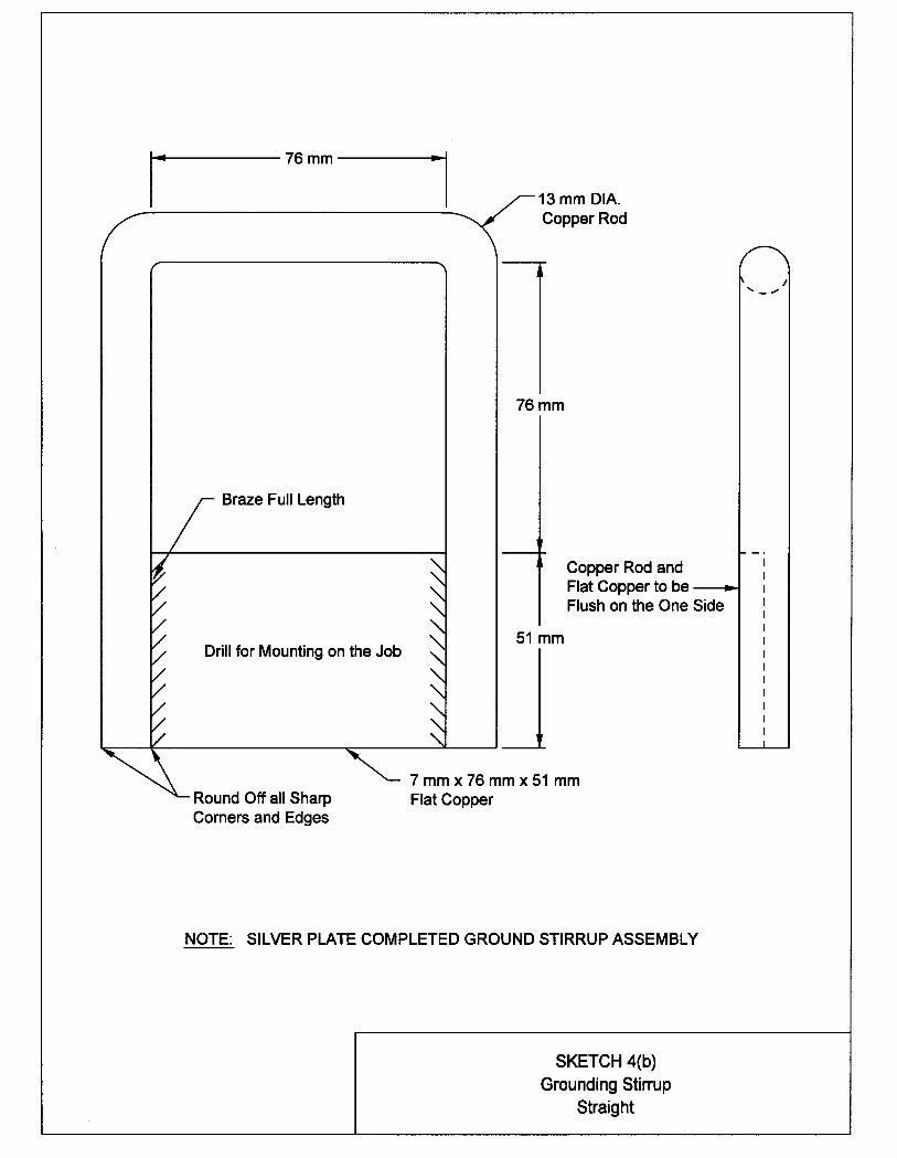
(a) A standard grounding stirrup [refer to sketches 4(a) and 4(b)] must be
installed on the ground bus in each incoming feeder termination compartment, approximately 0.3 meter inside the compartment door.

Requirements for the Design & Construction of Customer-Owned High-Voltage Substations
Section 6 – Ref. #4 Page 26
(b) A standard grounding stirrup [refer to sketches 4(a) and 4(b)] must be installed on each phase conductor in each incoming feeder termination compartment.
(c) Grounding using the 1-inch ball stud is also acceptable provided that the grounding cable is supplied and stored in a padlockable enclosure. This enclosure shall be supplied by the customer and shall be located adjacent to the switchgear. The minimum size of ground cable is 3/0 extra flex copper. Each incoming termination cell requires a set of grounding cables.
9.18.3 Cable Compartment
The ground connection in the cable termination compartments shall be positioned at an easily accessible location to accommodate Toronto Hydro ground clamp. When the incoming feeder termination is located at the upper compartment of the switchgear, a portable platform to facilitate the installation of grounds shall be provided. The platform shall be painted in gray and built according to the requirements shown in sketch 6.
9.18.4 Voltage Transformer Compartment
The ground connection in the voltage transformer compartment shall be provided with two 10/24 tapped holes to connect metering equipment ground leads.
9.18.5 Metallic Parts
Throughout the equipment all non-current carrying metallic parts shall be grounded.
9.18.6 Ground Grid Connections
The switchgear assembly ground bus shall be connected to the substation ground grid at two ends with minimum 2/0 copper ground wire.
9.19 Automatic Transfer between Normal and Standby Supply
9.19.1 Notification Requirements
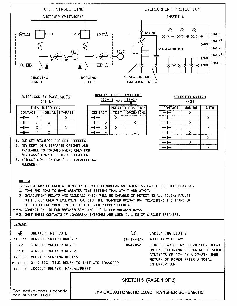
If manual operation of the automatic transfer switch is required, Toronto Hydro must be advised in advance. A typical automatic transfer scheme is shown on sketch 5.
9.19.2 Automatic Transfer Functional Requirements
(a) Under normal condition, the Normal breaker is closed, and the Standby
breaker is open. Upon loss of the Normal supply, the Normal breaker (or loadbreak switch) shall open and the Standby breaker (or loadbreak switch) shall close. Automatic transfer shall be initiated only if the Standby supply is energized and lock out of the transfer scheme has not activated [part (c) below].

Requirements for the Design & Construction of Customer-Owned High-Voltage Substations
Section 6 – Ref. #4 Page 27
(b) After a successful transfer from Normal to Standby, the supply shall remain on the Standby feeder even after the normal feeder has been restored. Toronto Hydro shall manually switch the customer back to Normal feeder. Automatic transfer back to the Normal feeder shall take place only in the event of power loss of the Standby feeder, and provided the Normal feeder is energized. An adjustable time delay (0 to 10 seconds range) shall be provided, before a transfer is initiated. This shall apply to both the transfers from Normal to Standby and from Standby to Normal feeders.
(c) The equipment shall include suitable overcurrent protective devices to prevent a transfer in the event of a fault occurring on or downstream from the auto transfer circuit breakers (or loadbreak switches). In the event of an operation of these devices, the breaker must trip and the automatic transfer shall lock out, and shall remain locked-out until it is manually reset by Toronto Hydro. The lock-out device shall be key operated such that the key shall be retained by Toronto Hydro or, alternatively, a cover shall be placed over the device and locked with a Toronto Hydro padlock. The current transformers supplying the overcurrent devices shall be located on the line side of the circuit breakers (or loadbreak switches).
(d) An Auto-Manual selector switch shall be provided, and the manual control of individual supply circuit breakers (or loadbreak switches) shall only be possible with the selector switch in the Manual position.
(e) The control switches of each breaker (or loadbreak switch) shall be connected such that a customer may manually transfer from Normal to Standby and from Standby to Normal by first tripping the supply breaker (or loadbreak switch), and then closing the Standby (or Normal) breaker (or loadbreak switch). The paralleling of the incoming feeders by the customer is not permitted.
(f) A key operated “Toronto Hydro Interlock” switch, with one key only for Toronto Hydro use shall be provided. The key shall remain trapped in the lock when the interlock circuit is in the “By–Pass” position. This is to permit the paralleling of feeders by Toronto Hydro.
(g) Indication lights shall conform to the following Toronto Hydro standard:
RED To indicate Breaker Closed GREEN To indicate Breaker Open WHITE A normally closed breaker has tripped and is
now open. BLUE Potential Indication YELLOW/AMBER Lockout operation.
(h) Motorized loadbreak switches shall be equipped with a positive means,
acceptable to Toronto Hydro, of making them inoperative when in the open position. This is to provide safe conditions when Toronto Hydro is making repairs or conducting tests.
Requirements for the Design & Construction of Customer-Owned High-Voltage Substations
Section 6 – Ref. #4 Page 28
(i) Voltage sensing transformers shall be arranged such that they can be easily disconnected from the feeder cables and locked in the disconnected position. This is to provide safe conditions when Toronto Hydro is making repairs or conducting tests on the feeder cables.
(j) Circuit breakers or loadbreak switches shall be equipped with an operation counter.
(k) Potential indication lights shall be provided for each ATS potential transformer associated with each incoming feeder.
9.20 Emergency Backup and Embedded Generation
9.20.1 Emergency Backup Generation
Where an emergency backup generator is installed by Customer to provide emergency power, paralleling of the emergency backup generator and Toronto Hydro power system is prohibited and it shall be positively precluded.
The following warning signs shall be provided to warn people of the presence of emergency backup generation: (1) CAUTION
EMERGENCY BACKUP GENERATOR FEEDER (2) CAUTION
EMERGENCY BACKUP GENERATOR The first warning sign is to be posted at the generator feeder cell, and the second warning sign is to be posted at the door of the switchroom, one sign per door.
9.20.2 Embedded Generation Embedded Generation shall comply with the requirements of “Toronto Hydro General Requirements for Parallel Generation” document in the Conditions of Service.
The following warning signs shall be provided to warn people of the presence of embedded generation: (1) CAUTION
EMBEDDED GENERATOR FEEDER (2) CAUTION
EMBEDDED GENERATOR
The first warning sign is to be posted at the generator feeder cell, and the second warning sign is to be posted at the door of the switchroom, one sign per door.

Requirements for the Design & Construction of Customer-Owned High-Voltage Substations
Section 6 – Ref. #4 Page 29
9.21 Pilot Wire Protection and Remote Tripping 9.21.1 Interstation Control Cables Cabinet (Refer to sketch 7)
Where pilot wire relay protection or remote circuit breaker tripping is required, a metal cabinet shall be provided and installed by the Customer for the termination of Toronto Hydro control cables (refer to sketch 7). The cabinet shall be mounted adjacent to the incoming primary cable duct face and shall not be smaller than 900 x 900 x 300 mm deep and shall be constructed as described in 10.4.2. (b) and (c). The Customer shall install a pair of #12 stranded wires between each pilot wire relay or remotely circuit provided exclusively for that purpose. The Customer shall install terminal blocks (10 points) in the cabinet as called for by Toronto Hydro.
9.21.2 Remote Tripping Relays (Refer to sketch 7)
If remote tripping is required, the customer shall provide 48V D.C. relays (with 2 normally open 15A contacts) mounted in a separate 300 x 300 x 150mm deep box. The box shall be attached to the pilot wire cabinet with 38mm bushing.
9.22 Test Blocks
Test blocks shall be installed in the current transformer secondary circuits on the relay panel for each set of protective relays to permit the disconnection of the protective relays and to short circuit the current transformer secondary circuit for test purposes.
Pilot wire relaying will require an isolating block to permit the disconnection of the relays outgoing communication lines for test purposes.
9.23 Annunciation – SF6 Low Pressure
(a) Each SF6 circuit breaker or any SF6 compartment within the electrical room shall have a gauge to monitor the low SF6 pressure installed within the circuit breaker or SF6 compartment.
(b) A warning light shall be provided on the control panel of each SF6 circuit breaker or any SF6 compartment to indicate “Low SF6 Gas Pressure”.
(c) A “Lamp Test” button shall be installed on the control panel of each individual circuit breaker or SF6 compartment for testing the individual warning light.
(d) A sign stating “Low SF6 Gas Pressure” shall be mounted above each warning light.
(e) The low pressure warning lights shall be simultaneously activated with the external light(s) as indicated in section 8.9.

Requirements for the Design & Construction of Customer-Owned High-Voltage Substations
Section 6 – Ref. #4 Page 30
9.24 Protective Relays
9.24.1 Relay Settings Relays that are under Toronto Hydro’s operating jurisdiction shall have provisions for Toronto Hydro seals to prevent unauthorized change of relay settings.
9.24.2 Current Transformer Secondary Wiring
The size of all current transformer secondary wiring shall be #10 AWG. 10. METERING REQUIREMENTS
For metering requirements, refer to the “Toronto Hydro Metering Requirements for 13.8kV & 27.6kV Customer-Owned Substations”, (Section 6, Reference #7 of Conditions of Service).
Requirements for the Design & Construction of Customer-Owned High-Voltage Substations
Section 6 – Ref. #4 Page 31
11. ASSOCIATED PUBLICATIONS The latest revisions of the Publication listed below shall apply. In case of conflict between the Publications below and T.H.E.S requirements, the latter will govern. Canadian Standards Association (CSA):
C22.2 No. 31 Switchgear Assemblies
C22.2 No. 94 Special Purpose Enclosures 2, 3, 4 and 5
C22/2 No. 193 High Voltage Full-load Interrupter Switches
CAN 3-C13 Instrument Transformers
Electrical and Electronic Manufacturers Association of Canada (EEMAC): G8-3.2 Metal Clad and Station-type Switchgear
G10-1 Revenue Metering Equipment in Switchgear Assemblies Institute of Electrical and Electronic Engineers (IEEE): Std 48 Test Procedures and Requirements for High Voltage ac Cable
Terminations Std 80 Outdoor Grounding Requirements
American National Standards Institute (ANSI):
C37.04 to C37.18 AC High Voltage Circuit Breakers (inclusive)
C37.20 Switchgear Assemblies: Including Metal-enclosed Bus C37.85 Safety Requirements for X-Radiation Limits for AC high voltage power
vacuum interrupters used in Power Switchgear. National Electrical Manufacturers Association (NEMA)
Requirements for the Design & Construction of Customer-Owned High-Voltage Substations
Section 6 – Ref. #4 Page 32
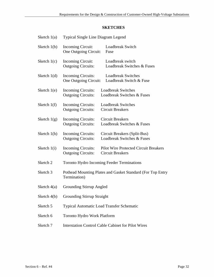
SKETCHES
Sketch 1(a) Typical Single Line Diagram Legend
Sketch 1(b) Incoming Circuit: Loadbreak Switch One Outgoing Circuit: Fuse
Sketch 1(c) Incoming Circuit: Loadbreak switch
Outgoing Circuits: Loadbreak Switches & Fuses
Sketch 1(d) Incoming Circuits: Loadbreak Switches One Outgoing Circuit: Loadbreak Switch & Fuse
Sketch 1(e) Incoming Circuits: Loadbreak Switches
Outgoing Circuits: Loadbreak Switches & Fuses
Sketch 1(f) Incoming Circuits: Loadbreak Switches Outgoing Circuits: Circuit Breakers
Sketch 1(g) Incoming Circuits: Circuit Breakers
Outgoing Circuits: Loadbreak Switches & Fuses Sketch 1(h) Incoming Circuits: Circuit Breakers (Split-Bus)
Outgoing Circuits: Loadbreak Switches & Fuses
Sketch 1(i) Incoming Circuits: Pilot Wire Protected Circuit Breakers Outgoing Circuits: Circuit Breakers
Sketch 2 Toronto Hydro Incoming Feeder Terminations
Sketch 3 Pothead Mounting Plates and Gasket Standard (For Top Entry
Termination)
Sketch 4(a) Grounding Stirrup Angled
Sketch 4(b) Grounding Stirrup Straight
Sketch 5 Typical Automatic Load Transfer Schematic
Sketch 6 Toronto Hydro Work Platform Sketch 7 Interstation Control Cable Cabinet for Pilot Wires