Embed Size (px)
Citation preview

PILOTS OPERATING HANDBOOK
Bowers Fly Baby Model 1AVersion 1.21
NOTE: This is a template to be used by Fly Baby owners for generation of Operating Handbooks for their specific aircraft. Specification and performance data must be replaced by specific values of the actual aircraft. Similarly, the other material in this handbook must be edited/removed in accordance to its applicability to the actual aircraft. No warranty, expressed or implied, is given regarding the accuracy of the information in this template.

Table of Contents
Table of Contents.............................................................................................................................21 Specifications...........................................................................................................................42 Performance.............................................................................................................................53 Limitations...............................................................................................................................64 Operating Characteristics.........................................................................................................7
4.1 General..............................................................................................................................74.2 Handling and Stability......................................................................................................74.3 Airspeed............................................................................................................................84.4 Stalls..................................................................................................................................84.5 Aerobatics.........................................................................................................................84.6 Pilot Comfort.....................................................................................................................84.7 Fuel Gauge........................................................................................................................9
5 Preflight Inspection................................................................................................................105.1 Cockpit............................................................................................................................105.2 Aft Fuselage and Tail......................................................................................................105.3 Wings..............................................................................................................................105.4 Landing Gear...................................................................................................................115.5 Nose, Engine, and Propeller............................................................................................11
6 Engine Start...........................................................................................................................126.1 When equipped with electrical starter.............................................................................126.2 When not equipped with electrical starter, with someone to turn the propeller for you.126.3 When hand-propping yourself........................................................................................12
7 Before Takeoff.......................................................................................................................147.1 Taxiing............................................................................................................................147.2 Pre-Takeoff Checklist.....................................................................................................14
8 Flight Procedures...................................................................................................................158.1 Takeoff............................................................................................................................158.2 Climb...............................................................................................................................158.3 Cruise..............................................................................................................................158.4 Descent............................................................................................................................15
BOWERS FLY BABY OPERATIONS HANDBOOKPage 2

8.5 Landing...........................................................................................................................159 Post-Landing..........................................................................................................................1610 Weight and Balance...............................................................................................................1711 Emergency Procedures..........................................................................................................18
11.1 General........................................................................................................................1811.2 Engine Failures............................................................................................................18
11.2.1 Engine Failure - Complete.......................................................................................1811.2.2 Engine Failure - Partial............................................................................................1811.2.3 Engine Failure Checklist..........................................................................................19
11.3 Flight Control Failure..................................................................................................1912 Suggested Condition Inspection Checklist............................................................................21
BOWERS FLY BABY OPERATIONS HANDBOOKPage 3
1 Specifications
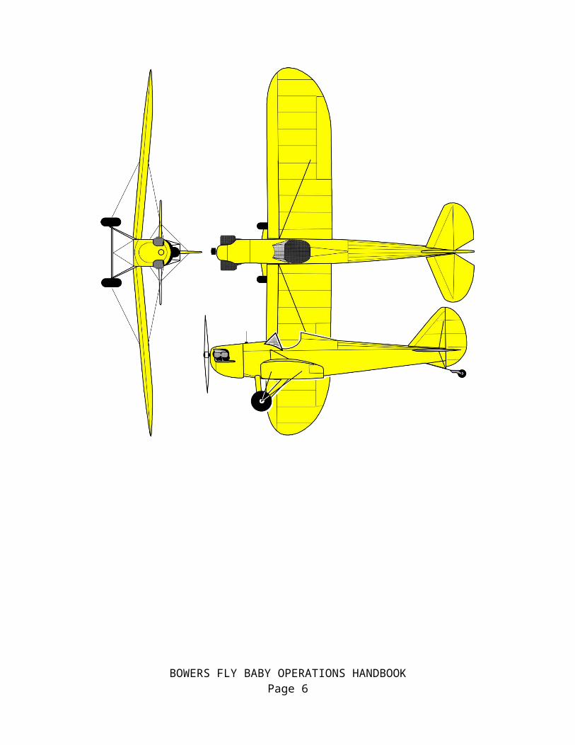
Wing Span: 28 feetLength: 18 feet 10.5 inchesHeight: 6 feet 11 inches (wing folded)
Tail Span: 7 feet 11.5 inchesWing Area: 120 sq ft
Empty Weight:Gross Weight:Fuel Capacity:
Note: Information provided is generic. Blanks indicate items which must be determined from the actual aircraft.
BOWERS FLY BABY OPERATIONS HANDBOOKPage 4

BOWERS FLY BABY OPERATIONS HANDBOOKPage 5
2 Performance
Stall Speed:Cruising Speed:
Rate of ClimbBest Rate of Climb Speed:
Best Angle of Climb Speed:Range:
Takeoff DistanceTakeoff over 50’ Obstacle:
Landing Distance:Landing over 50’ Obstacle:
Fuel Capacity:
Note: Information in this section must be determined from flight tests of the actual aircraft.
BOWERS FLY BABY OPERATIONS HANDBOOKPage 6
3 Limitations
1. This aircraft is licensed as an Experimental Amateur-Built aircraft, and must comply with the limitations of its certification category
2. Aerobatic maneuvers are prohibited3. Any major change to the aircraft, as defined in 14CFR 21.93, invalidates the Special
Airworthiness Certificate issued to the aircraft.4. This aircraft shall not be used for glider towing operations5. No person shall operate this aircraft unless, in the preceding 12 calendar months, it has
received a conditional inspection with the scope and breadth of 14CFR Part 43 Appendix D.
Note: Replace the above information, as necessary, with the contents of the Operating Limitations for the actual aircraft.
BOWERS FLY BABY OPERATIONS HANDBOOKPage 7

4 Operating Characteristics
The following section consists of material to familiarize new Fly Baby pilots with the operation and handling of the aircraft. It assumes that the aircraft is correctly rigged, and is flown with the CG in the correct range.
4.1 GeneralThe Fly Baby is a conventional-gear (taildragger) aircraft, and its air and ground handling is similar to common classic taildragger aircraft such as the J-3 Cub or Aeronca Champ.
Depending upon the height of the pilot and the design of the seat, visibility over the nose may be obstructed. In these cases, performing gentle S-turns while taxiing should allow sufficient forward visibility.
Between a combination of tailwheel spring stiffness, tire condition, tire inflation, temperature, and taxi speed, the airplane sometimes starts bouncing up and down on its tires as it taxies along. This is called the “Dribbles”. It's not dangerous, it doesn't affect control. If it occurs, just slow down or speed up.
If the aircraft is equipped with a Continental engine, the nose will tend to swing left as the takeoff roll begins. This is easily countered with rudder pedal pressure. New pilots may consider a gradual application of power to minimize the swing.
The pilot should attempt to raise the tail early in the takeoff run to accelerate better and to give visibility over the nose. Depending on the aircraft configuration, the change from tailwheel steering (when the tail is still on the ground) to aerodynamic steering (using the rudder as the tail comes up) may require a slight change in the amount of rudder pedal. In any case, the amount necessary will be decreasing as the aircraft accelerates.
A slight instability may appear around 35 MPH, but the aircraft quickly accelerates through that speed range. However, if a new pilot attempts to practice “high-speed taxiing,” the aircraft may remain in this range and give a false indication of handling problems.
It is recommended that pilots do not perform high-speed taxi testing, unless there is a specific issue that needs to be addressed.
4.2 Handling and StabilityThe Fly Baby has generous dihedral, and is very stable in yaw and roll. Stick pressures are very light, but good feedback is provided. Little actual stick movement is necessary in normal flight; it’s likely the stick will not move more than two inches from the neutral position.
However, this does not mean the aircraft will maintain level flight with the stick released. The aircraft does not include any offset in the vertical stabilizer to compensate for engine P-factor, so the airplane will have a tendency to yaw. An external, fixed trim tab is recommended on the rudder.
Also, if the wing rigging is not perfect, the aircraft will have a tendency to drop a wing and start turning if the stick is released. If the rigging is good enough, this is easily compensated for.
BOWERS FLY BABY OPERATIONS HANDBOOKPage 8

The ailerons should include gap seals; if omitted, the plane may be slightly more sluggish in roll.
Fly Baby stick forces are moderate in roll, but extremely light in pitch. Enough stick motion is necessary that the control does not feel overly sensitive.
Stock Fly Babies do not have cockpit-adjustable pitch trim. Control forces are light enough that it is not needed. An external tab should be installed on the elevator, and adjusted to the pilot’s desires. The ideal situation is adjusting the trim so that no elevator pressure is necessary at cruise with half a tank of fuel. This way, the airplane is slightly nose heavy with a full tank, but slightly tail-heavy as the fuel level drops. Again, this is easily compensated for.
4.3 AirspeedWith open cockpit and a network of external bracing wires, the Fly Baby is a high-drag, low-inertia aircraft. When power is reduced, airspeed drops quickly. In the event of an engine failure, the pilot should be prepared to add forward stick immediately to maintain flying speed.
Excellent audible feedback is received from the sound of the slipstream through the landing wires. However, the landing wires (the ones on the top of the wing) may “shiver” a bit in flight. This is normal, since the load disappears completely from the landing wires as the flying wires below wings support the aircraft in positive G flight.
4.4 StallsStalls in a Fly Baby are conventional, and proceeded by airframe buffeting.
If the aircraft is properly rigged and rudder is neutral, the stall break should be straight-ahead. However, due to the drag of the aircraft, the break will likely be more abrupt than a typical training aircraft. The nose will drop significantly at the break…again, easily controlled once a bit of airspeed is regained.
If the airplane is cross-controlled at the break, a wing will drop. This is easily recovered using rudder. The aircraft does not have a tendency towards spinning, but roll control at the stall should be limited to rudder.
Spin recovery, should one occur, is conventional.
4.5 AerobaticsThe Fly Baby is a personal sport aircraft, and it is recommended that aerobatics not be performed. One example of the airframe has been tested to +6 to -3 Gs without deformation, but variance in built quality will affect the ability of a given aircraft to withstand the stresses of aerobatics.
4.6 Pilot ComfortAs an open-cockpit airplane, the pilot’s personal environment depends on his or her clothing. Discomfort may affect safety; a chilled pilot is a distracted pilot.
The Fly Baby stock cockpit and windshield do very well at protecting the pilot from the slipstream and drafts, but the fact is that ambient air will be moving across the pilot’s body to some extent.
BOWERS FLY BABY OPERATIONS HANDBOOKPage 9

Every person has different tolerance for physical conditions. The following table can be used as a guideline for new Fly Baby pilots. This is a guide; notice that there is some overlap, depending on personal tolerance.
Suggested EquipmentTemperature Range (ºF)
>90 80 to 90
70 to 80
60 to 70
50 to 60
40 to 50
30 to 40
<30
Street clothes XLeather Helmet X X X X X X X
Light Jacket X XGloves X X X X
Scarf X X X XLeather Coat (A-2/G-1) X X X X
Sweatshirt X X XFace Mask X X X
Insulated Underwear X XHeavy Leather Coat
(B-3/IrvinX X
4.7 Fuel GaugeThe Fly Baby uses a J-3 Cub fuel indicator; a cork floating on the fuel, with a wire sticking out the cap to indicate fuel level. Slipstream forces can tend to pin the wire to the sleeve in the cap, and delay its movement down as the fuel is used. This can cause an unexpected sudden drop in fuel level when the cork and wire suddenly “unstick.”
Periodic wiping of the wire with oil is a good preventative. However, the best way to avoid fuel exhaustion is awareness of the pre-flight fullness of the tank, and the amount of time the aircraft has flown.
BOWERS FLY BABY OPERATIONS HANDBOOKPage 10

5 Preflight Inspection
Note: The following information is provided as a starting point for the owner to develop his or her own checklists. This checklist emphasizes Fly Baby-specific items during pre-flight; there
are other actions which are generic to aircraft pre-flight inspections. The owner should add these items as appropriate.
5.1 Cockpit
Seat secure, in position Shoulder harness draped across outside of turtledeck (to facilitate cockpit entry) Seat belts clear of rudder cables, draped diagonally across front of seat Spar pins in place Elevator pushrod attach bolt secure Aileron pushrods connected, with safety pins in place. Seatback and cockpit equipment clear of elevator walking beam behind seat Turtledeck latches secure Magneto Switch -- OFF Radio – OFF Transponder - OFF Master Switch -- OFF Carb Heat – COLD Required documentation -- Available In Airplane
5.2 Aft Fuselage and Tail
Surface check of Fuselage and tail Tail bracing cables, turnbuckles, and anchors Check hinges in elevators and rudder Elevator bolts in place Check the differential play in elevators No cracks/tears in tailwheel horn Shake tail slightly side-to-side, watching the motion of the tailwheel. Look for side-to-
side play around the tailpost mounting
5.3 Wings
Landing wires attached to anchors No distortion in fabric around landing wire/flying wire anchors Close examination of flying wire anchor plates (cracks, bends, nuts in place, etc.) "Plunk" both forward flying wires to see if they're about the same tension Check turnbuckles, cables, and arrow Check cables at wheel shackle...no fraying, kinking, etc.
BOWERS FLY BABY OPERATIONS HANDBOOKPage 11

Check Aileron for security and travel (note: the Aileron system has more upward travel than downward).
Check Aileron gap seal for security Check Aileron pushrod Pitot/Static boom: Undamaged, no obstructions
5.4 Landing Gear
Flying-wire attachment shackle undamaged Flying Wire attachment clevis pin in place and safetied No sign of degradation (loops, fraying, etc.) on flying wires Landing-Gear cross-brace cables, turnbuckles, and attach points Make sure wheel-attach bolts are in place Tire has proper inflation Brakes normal
5.5 Nose, Engine, and Propeller
Oil Level – 3 quarts or higher Propeller secure, no damage Cowling secure Spark Plug wires secure Front Air Intake clear Carburetor heat intake secure Exhaust system - Secure Fuel cap – secure Fuel indicator – cork floating, wire moves smoothly in cap
BOWERS FLY BABY OPERATIONS HANDBOOKPage 12

6 Engine Start
6.1 When equipped with electrical starter Seat Belts/Shoulder Harness attached Master Switch: ON Radio/Transponder: OFF Throttle: Idle or slightly cracked Carburetor Heat: OFF Mixture: RICH Magneto Switch: BOTH * Primer: AS REQUIRED Primer: SECURED Brakes: SET Propeller Area: CLEAR Starter: ACTIVATE Oil Pressure: In the green arc within 30 seconds
6.2 When not equipped with electrical starter, with someone to turn the propeller for you Brief the person on procedure and terminology Seat Belts/Shoulder Harness attached Throttle: Idle or slightly cracked Carburetor Heat: OFF Mixture: RICH Magneto Switch: OFF Primer: AS REQUIRED Primer: SECURED Brakes: SET Call: SWITCH OFF Have the person turn the engine over four blades Ensure the helper is clear of the propeller arc Call: CONTACT Magneto Switch: BOTH * Helper: Turn engine over On engine start, the oil pressure should be in the green arc within 30 seconds
6.3 When hand-propping yourself Wheel chocks in place Tail tied to solid object Seat Belts/Shoulder Harness ready for donning Throttle: Idle or slightly cracked Throttle lock: TIGHT Carburetor Heat: OFF Mixture: RICH Magneto Switch: OFF
BOWERS FLY BABY OPERATIONS HANDBOOKPage 13

Primer: AS REQUIRED Primer: SECURED Turn the engine over four blades Throttle: Verify position Magneto Switch: BOTH * Prop engine until it starts Throttle: Idle Go to left wing tip, walk inboard to wheel. Keep within touching distance of wing
leading edge Remove left chock, back away from fuselage until clear Go to left wing tip, walk inboard to wheel Remove right chock, , back away from fuselage until clear Note engine RPM, if engine has picked up, return to cockpit position to adjust throttle. Untie tail tiedown Climb into cockpit Brakes: Set Seat Belt/Should Harness: Attach
* Magneto to “both” if both mags have impulse coupling. If only one has an impulse coupling, the mag switch should be set to only that magneto for starting.
BOWERS FLY BABY OPERATIONS HANDBOOKPage 14

7 Before Takeoff
7.1 TaxiingDepending upon the seat position and the height of the pilot, minor S-turns may be necessary to see forward.
Between a combination of tailwheel spring stiffness, tire condition, tire inflation, temperature, and taxi speed, the airplane sometimes starts bouncing up and down on its tires as it taxies along. It's not dangerous, it doesn't affect control. If it occurs, just slow down or speed up.
7.2 Pre-Takeoff Checklist
Controls free Drop hand along seat belts, ensure they are clear of rudder cables Goggles down Scarf secure Jacket zipped Shoulder harness strap ends secured Nearby small children waved at Altimeter: SET Radio: SET Transponder: ON/ALT Brakes: SET Mixture: RICH Throttle: 1800 RPM Magneto Check Carb Heat check Throttle: Idle
BOWERS FLY BABY OPERATIONS HANDBOOKPage 15

8 Flight Procedures
8.1 Takeoff Position aircraft on centerline Center rudder and ailerons Elevator: SLIGHTLY FORWARD Throttle: Full Verify normal RPM achieved (typically 2100-2300 RPM, depending on engine and
propeller). Aircraft with Continental engines will need right rudder to track straight Raise tail when controllability gained. Note that the amount of rudder pedal pressure
needed to track straight may change slightly when the tail comes up. Rotate at 1.2 VSO
8.2 ClimbTypical climb is at 1.3 VSO… typically 65-70 MPH, however, actual displayed airspeed may vary by aircraft.
For most pilots, setting the horizon atop the fuel cap gives approximately the right climb angle (may vary by pilot height and seating position).
8.3 CruiseCruise RPM will vary by engine….2150 RPM for A65s, to 2400 RPM for C85s.
8.4 DescentAll power reductions on Continental engines should be preceded by carburetor heat.
8.5 Landing Mixture: RICH Carburetor heat: ON Power to ~1800 RPM abeam the numbers Approach speed 70-80 MPH (depending on airspeed indicator calibration) Reduce power to 1500 on turning final Power to idle as runway is made Slip as needed to eliminate excess altitude Fly the airplane to contact due to stiff landing gear
BOWERS FLY BABY OPERATIONS HANDBOOKPage 16
9 Post-Landing
Taxi clear on runway Goggles: UP Transponder: OFF or STANDBY Taxi to desired location Radio: OFF Transponder: OFF Throttle: IDLE Magnetos: OFF (aircraft with other than Stromberg carburetors may stop the engine by
going to full lean on the mixture).
BOWERS FLY BABY OPERATIONS HANDBOOKPage 17

10 Weight and Balance
Datum(Arm=0)
Allowable CG Range: 26 to 32 Inches Aft of Datum
Owner should insert specific CG information for his or her aircraft.
BOWERS FLY BABY OPERATIONS HANDBOOKPage 18

11 Emergency Procedures
11.1 GeneralThe Bowers Fly Baby is a conventional aircraft, and standard emergency procedures will suffice. The following sections provide insight into how unique features of the Fly Baby may affect standard procedures.
11.2 Engine FailuresAs ever, if the engine fails, the aircraft should be configured for an emergency landing prior to attempting in-air troubleshooting.
Due to the high drag of the Fly Baby airframe, the glide angle in an engine-out situation is fairly steep. If the engine fails, the pilot should be cautious not to select an emergency landing field too far away.
Engine failures can be complete or partial.
11.2.1 Engine Failure - CompleteDue to the simplicity of the systems on a stock Fly Baby, complete engine failure is generally due to either fuel management or mechanical problems with the carburetor.
Too often, a complete engine failure is due to fuel exhaustion…the pilot runs out of gas.
Fuel Starvation is a possibility as well…having fuel on board, but the flow, for some reason, has been interrupted. Stock Fly Babies have a single fuel valve for controlling gasoline flow to the engine; in the event of a complete failure, the position of this valve should be checked. However, the stock position is generally clear of any inadvertent movement that might accidentally change the position of the valve.
Mechanical issues with the carburetor are usually not fixable in flight. These might include disconnection of the throttle cable or carburetor heat cable from the carburetor, or internal problems with the carburetor itself. Once established on a glide to a safe landing area, the pilot may manipulate engine controls (mixture, etc.) to attempt to regain some power. However, remember the overwhelming goal is a safe landing…don’t let a temporary restoral of power lure you away from a good landing spot.
11.2.2 Engine Failure - PartialMost of the same problems that may cause complete engine failures may cause partial failures.
However, with a Continental engine, the first step upon detection of loss of power should be the application of carburetor heat. The small 4-cylinder Continentals are prone to carburetor ice. Remember that the application of carburetor heat may cause considerable roughness in engine operation as the ice is melted away and sucked into the engine. If you think there is icing, turn carb heat on and leave it on…don’t immediately turn it off if the engine starts to stagger. Give it time to work.
BOWERS FLY BABY OPERATIONS HANDBOOKPage 19
Conceivably, magneto failure can cause significant engine roughness. If the timing of one of the magnetos slips, it may prematurely fire the fuel in the cylinders. After turning on the carburetor heat, the next step is to perform an ordinary magneto check. If the engine returns to near-normal running on one magneto, continue to operate on it to the nearest airport.
11.2.3 Engine Failure ChecklistComplete or partial engine failure, pilot reaction should be about the same:
Carburetor Heat: ON Throttle: FULL Assume best glide airspeed (typically 65-70 MPH) Select landing location. Remember the Fly Baby glides steeply with the engine off Mixture: RICH Fuel valve: ON Magneto: LEFT Magneto: RIGHT Magneto: BOTH (assuming the check found no problems) If engine windmilling:
o Throttle: IDLEo Throttle: ½ Fullo Mixture: Full Leano Mixture: Half rich
If time permits:o Radio: MAYDAYo Transponder: 7700
If Emergency landing is inevitable:o Fuel valve: OFFo Magneto: OFFo Throttle: IDLEo Master switch: OFFo Shoulder harness/Lap Belt: AS TIGHT AS POSSIBLE
11.3 Flight Control FailureThere have been few cases of failures of Fly Baby flight controls. Here are some recommendations if one occurs:
Ailerons: Both ailerons are independently operated by pushrods connected to the control stick. If one aileron pushrod becomes disconnected, the other one would still work.
If a pushrod becomes disconnected, it is recommended that left-right stick movement be minimized to reduce the chance of a loose rod end jamming in structure.
Rudder: There have been a case of a rudder pedal becoming disconnected from the rudder cable (maintenance issue; wrong type of connector used). If this occurs, remember that the rudder cables themselves go past the pilot seat near the cockpit floor. It is possible to grab a lose cable and apply some pressure as needed.
BOWERS FLY BABY OPERATIONS HANDBOOKPage 20

Elevators: There have been no known cases of elevator control failure. Since the Fly Baby does not have a cockpit-adjustable pitch trim, this backup method of control is not available. The Fly Baby pitch attitude is sensitive to power settings, though, so the pitch attitude could be roughly controlled by throttle position.
Jammed Stick: The stock Fly Baby cockpit does not present a major hazard that a dropped piece of equipment (such as a glove) may jam the stick. Stock Fly Babies do not have a cockpit floor in the area forward of the seat, so jams are unlikely. However, some builders do add a floor in this area. If your aircraft has one, add a conical cover around the opening to minimize the chances of a dropped item jamming the stick.
BOWERS FLY BABY OPERATIONS HANDBOOKPage 21

12 Suggested Condition Inspection ChecklistBased on 14 CFR Part 43 Appendix D
(a) Remove or open all necessary inspection plates, access doors, fairings, and cowling.
(1) Thoroughly clean the aircraft and aircraft engine.
(b) Inspect the following components of the fuselage:
(1) Fabric and skin—for deterioration, distortion, other evidence of failure, and defective or insecure attachment of fittings, fabric drain holes clear.
(2) Systems and components—for improper installation, apparent defects, and unsatisfactory operation.
(3) Security of turtledeck
(c) Inspect the following components of the cockpit:
(1) Generally—for uncleanliness and loose equipment that might foul the controls.
(2) Seats and safety belts—for poor condition and apparent defects.
(3) Windshield—for deterioration and breakage.
(4) Instruments—for poor condition, mounting, marking, and (where practicable) improper operation.
(x) Master turnbuckle:
(i) Correctly tensioned and safetied
(ii) All related clevis pins safetied
(5) Flight and engine controls—for improper installation and improper operation.
(i) Control stick welds—condition and security
(ii) Aileron pushrods—condition and proper attachment of safety pins
(iii) Elevator pushrod—condition and security
(iv) Elevator walking beam—security and condition
(v) Rudder pedals—security and condition
a) Rudder cables- turnbuckles and cable attachment to the pedals.
(vi) Brake system—condition, improper inspection, brake-fluid level and potential brake-fluid leaks.
(vii) Engine controls – secure with smooth operation
(6) Proper installation and safetying of the spar pins
(i) Examine the condition of the attachment points on the STA 3 and STA 5 bulkheads
BOWERS FLY BABY OPERATIONS HANDBOOKPage 22

(7) All systems—for improper installation, poor general condition, apparent and obvious defects, and insecurity of attachment.
(8) Cockpit fuel system - for leaks and security
(i) Fuel tank - firmly strapped and no leaks
(ii) Shut-off valve – smooth operation and no leaks
(iii) Fuel hose – abrasion-free and no leaks
(9) Cockpit structure:
(i) Security and lamination of the bolted firewall to angle-bracket union
(ii) Lamination of the station 1 to 2 and lower fuselage-side “double truss” box sections
(iii) Security of the lower fuselage boxed longitudinal supports for floor boards and seat
(10) Seat – for condition and security
(d) Inspect components of the engine as follows:
(1) Engine section—for visual evidence of excessive oil or fuel leaks, and sources of such leaks.
(2) Studs and nuts—for improper torquing and obvious defects.
(3) Internal engine—for cylinder compression and for metal particles or foreign matter on screens and sump drain plugs. If there is weak cylinder compression, for improper internal condition and improper internal tolerances.
(4) Engine mount—for cracks, looseness of mounting, and looseness of engine to mount.
(5) Flexible vibration dampeners—for poor condition and deterioration.
(6) Engine controls—for defects, improper travel, and improper safetying.
(7) Lines, hoses, and clamps—for leaks, improper condition and looseness.
(8) Exhaust stacks—for cracks, defects, and improper attachment.
(9) Propeller—for cracks, nicks, and bends
(i) Propeller Bolts—for improper torquing and lack of safetying.
(10) Accessories—for apparent defects in security of mounting.
(11) All systems—for improper installation, poor general condition, defects, and insecure attachment.
(12) Cowling—for cracks, and defects.
(e) Inspect the following components of the landing gear group:
(1) All units—for poor condition and insecurity of attachment.
(2) Tires—for wear, cuts and improper pressurization
(3) Vee Struts—for damage, delamination, or missing nuts.
(4) Cross-bracing—for tension and proper safetying of turnbucklesBOWERS FLY BABY OPERATIONS HANDBOOK
Page 23

(5) Hydraulic lines—for leakage.
(6) Wheels—for cracks, defects, and condition of bearings.
(7) Master Axle – for bends, cracks, or visual deformation
(8) Brakes—for improper adjustment.
(f) Inspect all components of the wing for poor general condition, fabric or skin deterioration, distortion, evidence of failure, and insecurity of attachment, fabric drain holes clear.
(1) Flying and landing wire attachment plates—condition, cracks, and bends
(2) Flying and landing wire turnbuckles—condition, tension, and safety-wiring
(3) Flying wire shackle—distortion, or flaws in the attachment of the flying wires
(4) Landing wire terminals on the fuselage—distortion, or flaws in the attachment of the landing wires
(5) Master Turnbuckle—tightness safety-wire (or equivalent)
(6) Compression ribs—proper installation and condition
(7) Drag/anti-drag wires: for tension and turnbuckle safety wire
(8) Areas for particular attention when inspecting for water-related deterioration/damage:
(i) Forward of after spar at wing root
(ii) Wing wire junction blocks (both water damage and delamination)
(iii) Forward side of aileron spar
(7) Aileron bellcranks—proper installation and condition.
(8) Pitot boom—attachment and proper security
(i) Pitot and static lines—proper attachment
(g) Inspect all components and systems that make up the complete empennage assembly for poor general condition, fabric or skin deterioration, distortion, evidence of failure, insecure attachment, improper component installation, and improper component operation. Ensure water not collecting in compartment forward of tailpost, fabric and other water drain holes clear.
(1) Bracing wires—for proper tension
(2) Turnbuckles—for proper safetying
(3) Tailspring attach brackets—for condition and solid attachment
(4) Rudder and tailwheel control horns—for bends and cracks
(5) Tailwheel assembly—general condition
(6) Tailwheel spring – security and condition
(7) Tailpost: condition at lower tailpost to tailwheel bracket union
(h) Inspect (where applicable) the following components of the radio group:
BOWERS FLY BABY OPERATIONS HANDBOOKPage 24
(1) Radio and electronic equipment—for improper installation and insecure mounting.
(2) Wiring and conduits—for improper routing, insecure mounting, and obvious defects.
(3) Bonding and shielding—for improper installation and poor condition.
(4) Antennas—for poor condition, insecure mounting, and improper operation.
(i) Inspect (where applicable) each installed miscellaneous item that is not otherwise covered by this listing for improper installation and improper operation.
BOWERS FLY BABY OPERATIONS HANDBOOKPage 25