Embed Size (px)
Citation preview

Table of Contents
Cover Sheet ....................................................................................................................................................2 Warnings and Errors ................................................................................................................................3 Input Echo.......................................................................................................................................................4 XY Coordinate Calculations...............................................................................................................8 Internal Pressure Calculations.....................................................................................................9 External Pressure Calculations...................................................................................................12 Element and Detail Weights.............................................................................................................14 Nozzle Flange MAWP.................................................................................................................................15 Wind Load Calculation .........................................................................................................................16 Earthquake Load Calculation ..........................................................................................................18 Center of Gravity Calculation .....................................................................................................19 Horizontal Vessel Analysis (Ope.) ...........................................................................................20 Horizontal Vessel Analysis (Test) ...........................................................................................25 Nozzle Calcs. Inspection..................................................................................................................30 Nozzle Calcs. Outlet............................................................................................................................34 Nozzle Calcs. Manhole .........................................................................................................................38 Nozzle Calcs. Drain ..............................................................................................................................42 Nozzle Calcs. Inlet ..............................................................................................................................45 Nozzle Schedule ........................................................................................................................................49 Nozzle Summary...........................................................................................................................................50 Vessel Design Summary .........................................................................................................................51 Problems/Failures Summary ...............................................................................................................53
Cover Page
2
DESIGN CALCULATION In Accordance with ASME Section VIII Division 1 ASME Code Version : 2007 Analysis Performed by : KEDKEP CONSULTING, INC. Job File : E:\WEB\HORIZONTAL TANK.PVI Date of Analysis : Oct 23,2008 PV Elite 2008, May 2008
PV Elite 2008 Licensee: KEDKEP CONSULTING, INC. FileName : Horizontal Tank ------------------------------- Warnings and Errors Step: 0 4:19p Oct 23,2008
3
Class From To : Basic Element Checks. ========================================================================== Class From To: Check of Additional Element Data ========================================================================== There were no geometry errors or warnings. PV Elite 2008 c1993-2008 by COADE Engineering Software
PV Elite 2008 Licensee: KEDKEP CONSULTING, INC. FileName : Horizontal Tank ------------------------------- Input Echo Step: 1 4:19p Oct 23,2008
4
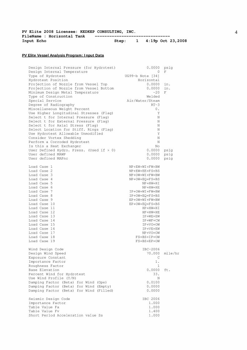
PV Elite Vessel Analysis Program: Input Data Design Internal Pressure (for Hydrotest) 0.0000 psig Design Internal Temperature 0 F Type of Hydrotest UG99-b Note [34] Hydrotest Position Horizontal Projection of Nozzle from Vessel Top 0.0000 in. Projection of Nozzle from Vessel Bottom 0.0000 in. Minimum Design Metal Temperature -20 F Type of Construction Welded Special Service Air/Water/Steam Degree of Radiography RT-3 Miscellaneous Weight Percent 0. Use Higher Longitudinal Stresses (Flag) Y Select t for Internal Pressure (Flag) N Select t for External Pressure (Flag) N Select t for Axial Stress (Flag) N Select Location for Stiff. Rings (Flag) N Use Hydrotest Allowable Unmodified Y Consider Vortex Shedding N Perform a Corroded Hydrotest N Is this a Heat Exchanger No User Defined Hydro. Press. (Used if > 0) 0.0000 psig User defined MAWP 0.0000 psig User defined MAPnc 0.0000 psig Load Case 1 NP+EW+WI+FW+BW Load Case 2 NP+EW+EE+FS+BS Load Case 3 NP+OW+WI+FW+BW Load Case 4 NP+OW+EQ+FS+BS Load Case 5 NP+HW+HI Load Case 6 NP+HW+HE Load Case 7 IP+OW+WI+FW+BW Load Case 8 IP+OW+EQ+FS+BS Load Case 9 EP+OW+WI+FW+BW Load Case 10 EP+OW+EQ+FS+BS Load Case 11 HP+HW+HI Load Case 12 HP+HW+HE Load Case 13 IP+WE+EW Load Case 14 IP+WF+CW Load Case 15 IP+VO+OW Load Case 16 IP+VE+EW Load Case 17 NP+VO+OW Load Case 18 FS+BS+IP+OW Load Case 19 FS+BS+EP+OW Wind Design Code IBC-2006 Design Wind Speed 70.000 mile/hr Exposure Constant C Importance Factor 1. Roughness Factor 1 Base Elevation 0.0000 ft. Percent Wind for Hydrotest 33. Use Wind Profile (Y/N) N Damping Factor (Beta) for Wind (Ope) 0.0100 Damping Factor (Beta) for Wind (Empty) 0.0000 Damping Factor (Beta) for Wind (Filled) 0.0000 Seismic Design Code IBC 2006 Importance Factor 1.000 Table Value Fa 1.000 Table Value Fv 1.400 Short Period Acceleration value Ss 1.000
PV Elite 2008 Licensee: KEDKEP CONSULTING, INC. FileName : Horizontal Tank ------------------------------- Input Echo Step: 1 4:19p Oct 23,2008
5
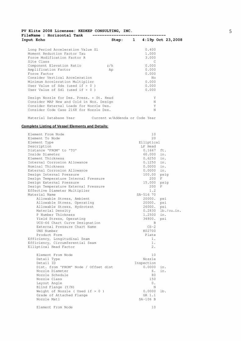
Long Period Acceleration Value Sl 0.400 Moment Reduction Factor Tau 1.000 Force Modification Factor R 3.000 Site Class C Component Elevation Ratio z/h 0.000 Amplification Factor Ap 0.000 Force Factor 0.000 Consider Vertical Acceleration No Minimum Acceleration Multiplier 0.000 User Value of Sds (used if > 0 ) 0.000 User Value of Sd1 (used if > 0 ) 0.000 Design Nozzle for Des. Press. + St. Head Y Consider MAP New and Cold in Noz. Design N Consider External Loads for Nozzle Des. Y Consider Code Case 2168 for Nozzle Des. N Material Database Year Current w/Addenda or Code Year Complete Listing of Vessel Elements and Details: Element From Node 10 Element To Node 20 Element Type Elliptical Description LF Head Distance "FROM" to "TO" 0.1667 ft. Inside Diameter 60.000 in. Element Thickness 0.6250 in. Internal Corrosion Allowance 0.1250 in. Nominal Thickness 0.0000 in. External Corrosion Allowance 0.0000 in. Design Internal Pressure 100.00 psig Design Temperature Internal Pressure 200 F Design External Pressure 15.000 psig Design Temperature External Pressure 200 F Effective Diameter Multiplier 1.2 Material Name SA-516 70 Allowable Stress, Ambient 20000. psi Allowable Stress, Operating 20000. psi Allowable Stress, Hydrotest 26000. psi Material Density 0.2830 lb./cu.in. P Number Thickness 1.2500 in. Yield Stress, Operating 34800. psi UCS-66 Chart Curve Designation B External Pressure Chart Name CS-2 UNS Number K02700 Product Form Plate Efficiency, Longitudinal Seam 1. Efficiency, Circumferential Seam 1. Elliptical Head Factor 2. Element From Node 10 Detail Type Nozzle Detail ID Inspection Dist. from "FROM" Node / Offset dist 0.0000 in. Nozzle Diameter 6. in. Nozzle Schedule 80 Nozzle Class 150 Layout Angle 0. Blind Flange (Y/N) N Weight of Nozzle ( Used if > 0 ) 0.0000 lb. Grade of Attached Flange GR 1.1 Nozzle Matl SA-106 B Element From Node 10
PV Elite 2008 Licensee: KEDKEP CONSULTING, INC. FileName : Horizontal Tank ------------------------------- Input Echo Step: 1 4:19p Oct 23,2008
6
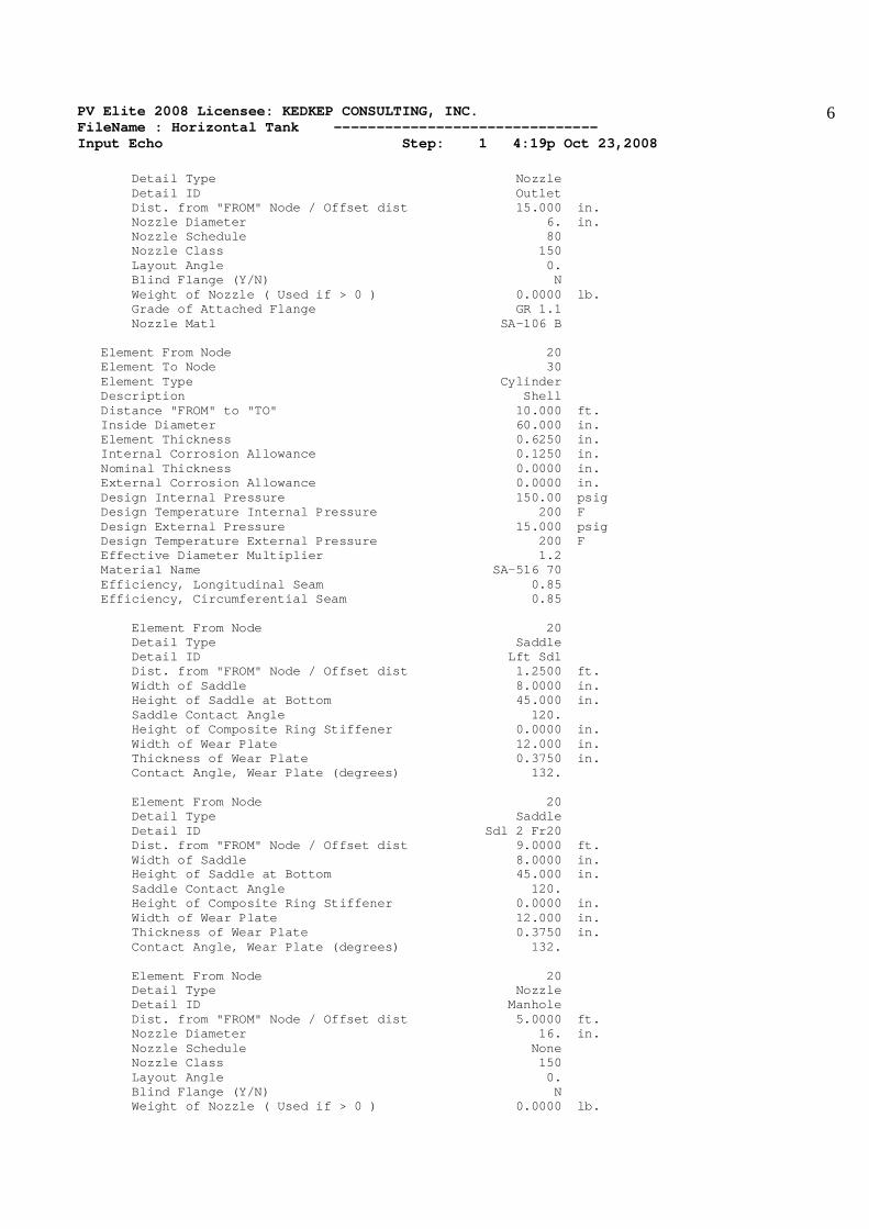
Detail Type Nozzle Detail ID Outlet Dist. from "FROM" Node / Offset dist 15.000 in. Nozzle Diameter 6. in. Nozzle Schedule 80 Nozzle Class 150 Layout Angle 0. Blind Flange (Y/N) N Weight of Nozzle ( Used if > 0 ) 0.0000 lb. Grade of Attached Flange GR 1.1 Nozzle Matl SA-106 B Element From Node 20 Element To Node 30 Element Type Cylinder Description Shell Distance "FROM" to "TO" 10.000 ft. Inside Diameter 60.000 in. Element Thickness 0.6250 in. Internal Corrosion Allowance 0.1250 in. Nominal Thickness 0.0000 in. External Corrosion Allowance 0.0000 in. Design Internal Pressure 150.00 psig Design Temperature Internal Pressure 200 F Design External Pressure 15.000 psig Design Temperature External Pressure 200 F Effective Diameter Multiplier 1.2 Material Name SA-516 70 Efficiency, Longitudinal Seam 0.85 Efficiency, Circumferential Seam 0.85 Element From Node 20 Detail Type Saddle Detail ID Lft Sdl Dist. from "FROM" Node / Offset dist 1.2500 ft. Width of Saddle 8.0000 in. Height of Saddle at Bottom 45.000 in. Saddle Contact Angle 120. Height of Composite Ring Stiffener 0.0000 in. Width of Wear Plate 12.000 in. Thickness of Wear Plate 0.3750 in. Contact Angle, Wear Plate (degrees) 132. Element From Node 20 Detail Type Saddle Detail ID Sdl 2 Fr20 Dist. from "FROM" Node / Offset dist 9.0000 ft. Width of Saddle 8.0000 in. Height of Saddle at Bottom 45.000 in. Saddle Contact Angle 120. Height of Composite Ring Stiffener 0.0000 in. Width of Wear Plate 12.000 in. Thickness of Wear Plate 0.3750 in. Contact Angle, Wear Plate (degrees) 132. Element From Node 20 Detail Type Nozzle Detail ID Manhole Dist. from "FROM" Node / Offset dist 5.0000 ft. Nozzle Diameter 16. in. Nozzle Schedule None Nozzle Class 150 Layout Angle 0. Blind Flange (Y/N) N Weight of Nozzle ( Used if > 0 ) 0.0000 lb.
PV Elite 2008 Licensee: KEDKEP CONSULTING, INC. FileName : Horizontal Tank ------------------------------- Input Echo Step: 1 4:19p Oct 23,2008
7
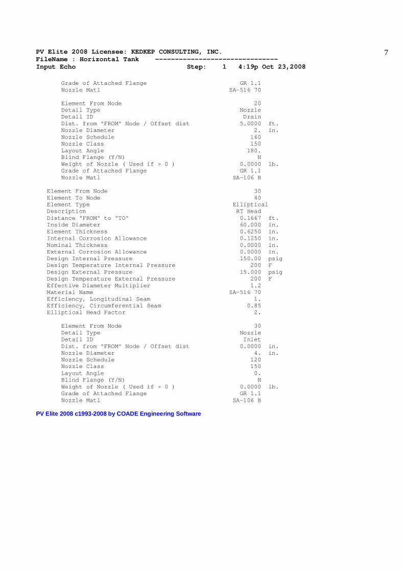
Grade of Attached Flange GR 1.1 Nozzle Matl SA-516 70 Element From Node 20 Detail Type Nozzle Detail ID Drain Dist. from "FROM" Node / Offset dist 5.0000 ft. Nozzle Diameter 2. in. Nozzle Schedule 160 Nozzle Class 150 Layout Angle 180. Blind Flange (Y/N) N Weight of Nozzle ( Used if > 0 ) 0.0000 lb. Grade of Attached Flange GR 1.1 Nozzle Matl SA-106 B Element From Node 30 Element To Node 40 Element Type Elliptical Description RT Head Distance "FROM" to "TO" 0.1667 ft. Inside Diameter 60.000 in. Element Thickness 0.6250 in. Internal Corrosion Allowance 0.1250 in. Nominal Thickness 0.0000 in. External Corrosion Allowance 0.0000 in. Design Internal Pressure 150.00 psig Design Temperature Internal Pressure 200 F Design External Pressure 15.000 psig Design Temperature External Pressure 200 F Effective Diameter Multiplier 1.2 Material Name SA-516 70 Efficiency, Longitudinal Seam 1. Efficiency, Circumferential Seam 0.85 Elliptical Head Factor 2. Element From Node 30 Detail Type Nozzle Detail ID Inlet Dist. from "FROM" Node / Offset dist 0.0000 in. Nozzle Diameter 4. in. Nozzle Schedule 120 Nozzle Class 150 Layout Angle 0. Blind Flange (Y/N) N Weight of Nozzle ( Used if > 0 ) 0.0000 lb. Grade of Attached Flange GR 1.1 Nozzle Matl SA-106 B PV Elite 2008 c1993-2008 by COADE Engineering Software
PV Elite 2008 Licensee: KEDKEP CONSULTING, INC. FileName : Horizontal Tank ------------------------------- XY Coordinate Calculations Step: 2 4:19p Oct 23,2008
8
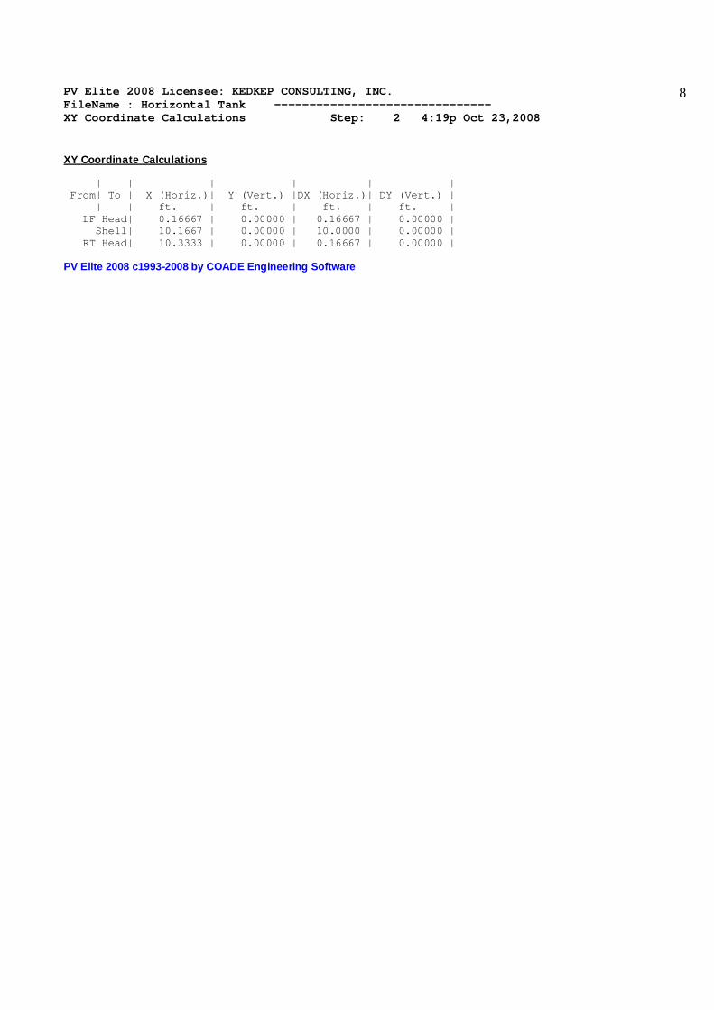
XY Coordinate Calculations | | | | | | From| To | X (Horiz.)| Y (Vert.) |DX (Horiz.)| DY (Vert.) | | | ft. | ft. | ft. | ft. | LF Head| 0.16667 | 0.00000 | 0.16667 | 0.00000 | Shell| 10.1667 | 0.00000 | 10.0000 | 0.00000 | RT Head| 10.3333 | 0.00000 | 0.16667 | 0.00000 | PV Elite 2008 c1993-2008 by COADE Engineering Software

PV Elite 2008 Licensee: KEDKEP CONSULTING, INC. FileName : Horizontal Tank ------------------------------- Internal Pressure Calculations Step: 3 4:19p Oct 23,2008
9
Element Thickness, Pressure, Diameter and Allowable Stress : | | Int. Press | Nominal | Total Corr| Element | Allowable | From| To | + Liq. Hd | Thickness | Allowance | Diameter | Stress(SE)| | | psig | in. | in. | in. | psi | LF Head| 100.000 | ... | 0.12500 | 60.0000 | 20000.0 | Shell| 150.000 | ... | 0.12500 | 60.0000 | 17000.0 | RT Head| 150.000 | ... | 0.12500 | 60.0000 | 20000.0 | Element Required Thickness and MAWP : | | Design | M.A.W.P. | M.A.P. | Actual | Required | From| To | Pressure | Corroded | New & Cold | Thickness | Thickness | | | psig | psig | psig | in. | in. | LF Head| 100.000 | 331.400 | 415.800 | 0.62500 | 0.27570 | Shell| 150.000 | 279.376 | 349.794 | 0.62500 | 0.39222 | RT Head| 150.000 | 331.400 | 415.800 | 0.62500 | 0.35111 | Minimum 260.000 285.000 Note : The M.A.W.P is Governed by an ANSI Flange ! Note : The M.A.P.(NC) is Governed by a Flange ! Internal Pressure Calculation Results : ASME Code, Section VIII, Division 1, 2007 Elliptical Head From 10 To 20 SA-516 70 , UCS-66 Crv. B at 200 F LF Head Thickness Due to Internal Pressure [Tr]: = (P*D*K)/(2*S*E-0.2*P) Appendix 1-4(c) = (100.000*60.2500*0.12)/(2*20000.00*1.00-0.2*100.000) = 0.1507 + 0.1250 = 0.2757 in. Max. Allowable Working Pressure at given Thickness, corroded [MAWP]: = (2*S*E*t)/(K*D+0.2*t) per Appendix 1-4 (c) = (2*20000.00*1.00*0.5000)/(1.00*60.2500+0.2*0.5000) = 331.400 psig Maximum Allowable Pressure, New and Cold [MAPNC]: = (2*S*E*t)/(K*D+0.2*t) per Appendix 1-4 (c) = (2*20000.00*1.00*0.6250)/(1.00*60.0000+0.2*0.6250) = 415.800 psig Actual stress at given pressure and thickness, corroded [Sact]: = (P*(K*D+0.2*t))/(2*E*t) = (100.000*(1.00*60.2500+0.2*0.5000))/(2*1.00*0.5000) = 6035.000 psi Required Thickness of Straight Flange = 0.276 in. Percent Elongation per UCS-79 (75*tnom/Rf)*(1-Rf/Ro) 4.548 % Min Metal Temp. w/o impact per UCS-66 6 F Min Metal Temp. at Rqd thickness (UCS 66.1)[rat 0.30] -134 F Min Metal Temp. w/o impact per UG-20(f) -20 F Cylindrical Shell From 20 To 30 SA-516 70 , UCS-66 Crv. B at 200 F Shell Thickness Due to Internal Pressure [Tr]:

PV Elite 2008 Licensee: KEDKEP CONSULTING, INC. FileName : Horizontal Tank ------------------------------- Internal Pressure Calculations Step: 3 4:19p Oct 23,2008
10
= (P*R)/(S*E-0.6*P) per UG-27 (c)(1) = (150.000*30.1250)/(20000.00*0.85-0.6*150.000) = 0.2672 + 0.1250 = 0.3922 in. Max. Allowable Working Pressure at given Thickness, corroded [MAWP]: = (S*E*t)/(R+0.6*t) per UG-27 (c)(1) = (20000.00*0.85*0.5000)/(30.1250+0.6*0.5000) = 279.376 psig Maximum Allowable Pressure, New and Cold [MAPNC]: = (S*E*t)/(R+0.6*t) per UG-27 (c)(1) = (20000.00*0.85*0.6250)/(30.0000+0.6*0.6250) = 349.794 psig Actual stress at given pressure and thickness, corroded [Sact]: = (P*(R+0.6*t))/(E*t) = (150.000*(30.1250+0.6*0.5000))/(0.85*0.5000) = 10738.235 psi Percent Elongation per UCS-79 (50*tnom/Rf)*(1-Rf/Ro) 1.031 % Min Metal Temp. w/o impact per UCS-66 6 F Min Metal Temp. at Rqd thickness (UCS 66.1)[rat 0.45] -55 F Min Metal Temp. w/o impact per UG-20(f) -20 F Elliptical Head From 30 To 40 SA-516 70 , UCS-66 Crv. B at 200 F RT Head Thickness Due to Internal Pressure [Tr]: = (P*D*K)/(2*S*E-0.2*P) Appendix 1-4(c) = (150.000*60.2500*0.12)/(2*20000.00*1.00-0.2*150.000) = 0.2261 + 0.1250 = 0.3511 in. Max. Allowable Working Pressure at given Thickness, corroded [MAWP]: = (2*S*E*t)/(K*D+0.2*t) per Appendix 1-4 (c) = (2*20000.00*1.00*0.5000)/(1.00*60.2500+0.2*0.5000) = 331.400 psig Maximum Allowable Pressure, New and Cold [MAPNC]: = (2*S*E*t)/(K*D+0.2*t) per Appendix 1-4 (c) = (2*20000.00*1.00*0.6250)/(1.00*60.0000+0.2*0.6250) = 415.800 psig Actual stress at given pressure and thickness, corroded [Sact]: = (P*(K*D+0.2*t))/(2*E*t) = (150.000*(1.00*60.2500+0.2*0.5000))/(2*1.00*0.5000) = 9052.500 psi Required Thickness of Straight Flange = 0.352 in. Percent Elongation per UCS-79 (75*tnom/Rf)*(1-Rf/Ro) 4.548 % Min Metal Temp. w/o impact per UCS-66 6 F Min Metal Temp. at Rqd thickness (UCS 66.1)[rat 0.45] -55 F Min Metal Temp. w/o impact per UG-20(f) -20 F MINIMUM METAL DESIGN TEMPERATURE RESULTS : Minimum Metal Temp. w/o impact per UCS-66 6. F Minimum Metal Temp. at Required thickness -55. F Note: Heads and Shells Exempted to -20F (-29C) by paragraph UG-20F Minimum Design Metal Temperature ( Entered by User ) -20. F

PV Elite 2008 Licensee: KEDKEP CONSULTING, INC. FileName : Horizontal Tank ------------------------------- Internal Pressure Calculations Step: 3 4:19p Oct 23,2008
11
Hydrostatic Test Pressure Results: Pressure per UG99b = 1.3 * M.A.W.P. * Sa/S 338.000 psig Pressure per UG99b[34] = 1.3 * Design Pres * Sa/S 0.000 psig Pressure per UG99c = 1.3 * M.A.P. - Head(Hyd) 370.500 psig Pressure per UG100 = 1.1 * M.A.W.P. * Sa/S 286.000 psig UG-99(b) Note 34, Test Pressure Calculation: = Test Factor * Design Pressure * Stress Ratio = 1.3 * 0.000 * 1.000 = 0.000 psig Horizontal Hydrotest performed in accordance with: UG-99b (Note 34) Stresses on Elements due to Hydrostatic Test Pressure: From To Stress Allowable Ratio Pressure Elements Suitable for Internal Pressure. PV Elite 2008 c1993-2008 by COADE Engineering Software
PV Elite 2008 Licensee: KEDKEP CONSULTING, INC. FileName : Horizontal Tank ------------------------------- External Pressure Calculations Step: 4 4:19p Oct 23,2008
12
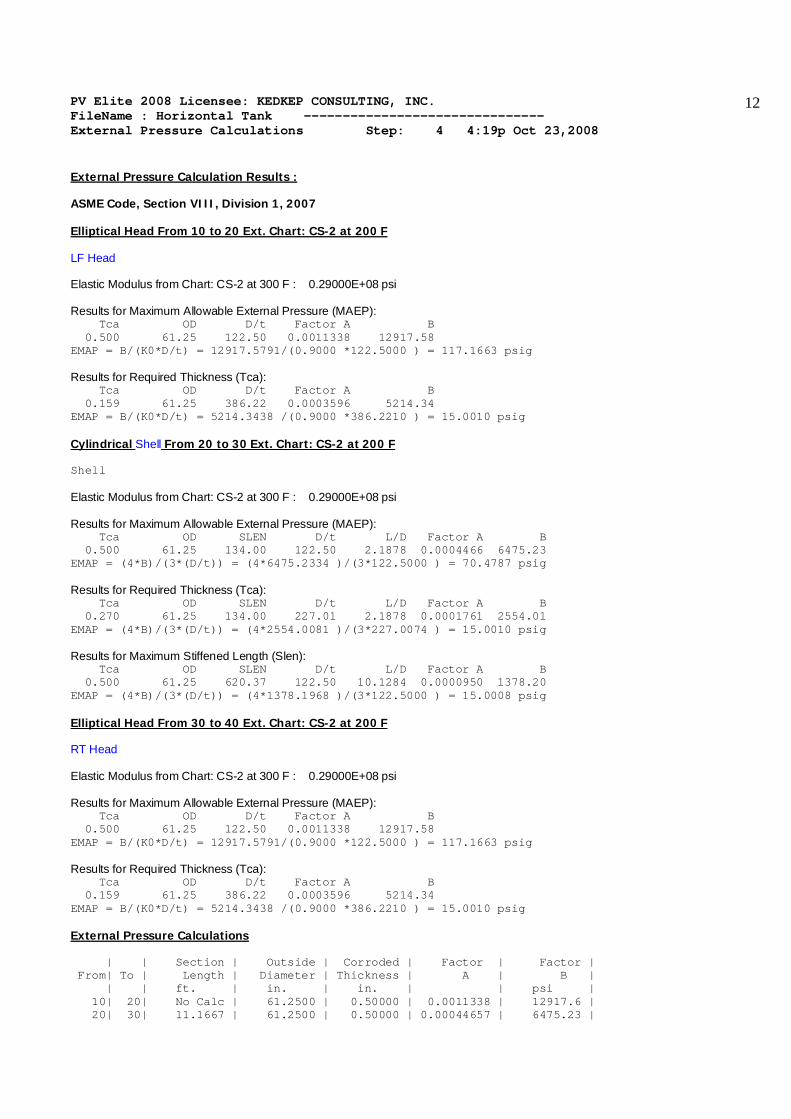
External Pressure Calculation Results : ASME Code, Section VIII, Division 1, 2007 Elliptical Head From 10 to 20 Ext. Chart: CS-2 at 200 F LF Head Elastic Modulus from Chart: CS-2 at 300 F : 0.29000E+08 psi Results for Maximum Allowable External Pressure (MAEP): Tca OD D/t Factor A B 0.500 61.25 122.50 0.0011338 12917.58 EMAP = B/(K0*D/t) = 12917.5791/(0.9000 *122.5000 ) = 117.1663 psig Results for Required Thickness (Tca): Tca OD D/t Factor A B 0.159 61.25 386.22 0.0003596 5214.34 EMAP = B/(K0*D/t) = 5214.3438 /(0.9000 *386.2210 ) = 15.0010 psig Cylindrical Shell From 20 to 30 Ext. Chart: CS-2 at 200 F Shell Elastic Modulus from Chart: CS-2 at 300 F : 0.29000E+08 psi Results for Maximum Allowable External Pressure (MAEP): Tca OD SLEN D/t L/D Factor A B 0.500 61.25 134.00 122.50 2.1878 0.0004466 6475.23 EMAP = (4*B)/(3*(D/t)) = (4*6475.2334 )/(3*122.5000 ) = 70.4787 psig Results for Required Thickness (Tca): Tca OD SLEN D/t L/D Factor A B 0.270 61.25 134.00 227.01 2.1878 0.0001761 2554.01 EMAP = (4*B)/(3*(D/t)) = (4*2554.0081 )/(3*227.0074 ) = 15.0010 psig Results for Maximum Stiffened Length (Slen): Tca OD SLEN D/t L/D Factor A B 0.500 61.25 620.37 122.50 10.1284 0.0000950 1378.20 EMAP = (4*B)/(3*(D/t)) = (4*1378.1968 )/(3*122.5000 ) = 15.0008 psig Elliptical Head From 30 to 40 Ext. Chart: CS-2 at 200 F RT Head Elastic Modulus from Chart: CS-2 at 300 F : 0.29000E+08 psi Results for Maximum Allowable External Pressure (MAEP): Tca OD D/t Factor A B 0.500 61.25 122.50 0.0011338 12917.58 EMAP = B/(K0*D/t) = 12917.5791/(0.9000 *122.5000 ) = 117.1663 psig Results for Required Thickness (Tca): Tca OD D/t Factor A B 0.159 61.25 386.22 0.0003596 5214.34 EMAP = B/(K0*D/t) = 5214.3438 /(0.9000 *386.2210 ) = 15.0010 psig External Pressure Calculations | | Section | Outside | Corroded | Factor | Factor | From| To | Length | Diameter | Thickness | A | B | | | ft. | in. | in. | | psi | 10| 20| No Calc | 61.2500 | 0.50000 | 0.0011338 | 12917.6 | 20| 30| 11.1667 | 61.2500 | 0.50000 | 0.00044657 | 6475.23 |
PV Elite 2008 Licensee: KEDKEP CONSULTING, INC. FileName : Horizontal Tank ------------------------------- External Pressure Calculations Step: 4 4:19p Oct 23,2008
13
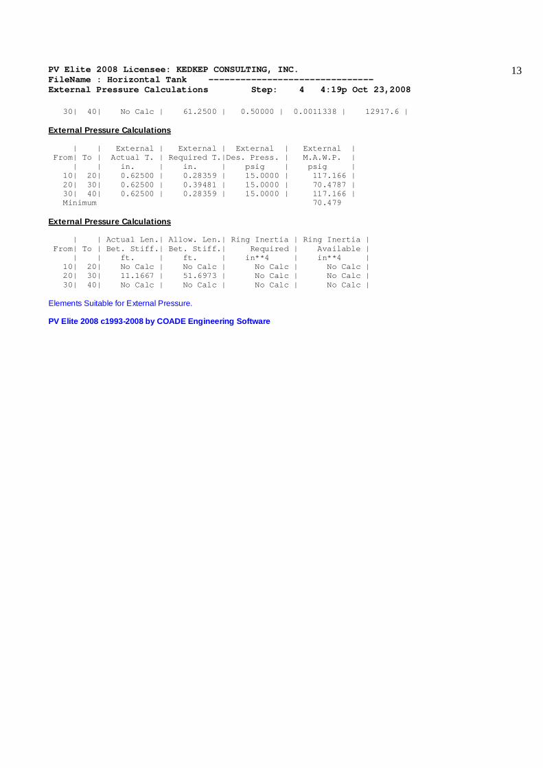
30| 40| No Calc | 61.2500 | 0.50000 | 0.0011338 | 12917.6 | External Pressure Calculations | | External | External | External | External | From| To | Actual T. | Required T.|Des. Press. | M.A.W.P. | | | in. | in. | psig | psig | 10| 20| 0.62500 | 0.28359 | 15.0000 | 117.166 | 20| 30| 0.62500 | 0.39481 | 15.0000 | 70.4787 | 30| 40| 0.62500 | 0.28359 | 15.0000 | 117.166 | Minimum 70.479 External Pressure Calculations | | Actual Len.| Allow. Len.| Ring Inertia | Ring Inertia | From| To | Bet. Stiff.| Bet. Stiff.| Required | Available | | | ft. | ft. | in**4 | in**4 | 10| 20| No Calc | No Calc | No Calc | No Calc | 20| 30| 11.1667 | 51.6973 | No Calc | No Calc | 30| 40| No Calc | No Calc | No Calc | No Calc | Elements Suitable for External Pressure. PV Elite 2008 c1993-2008 by COADE Engineering Software
PV Elite 2008 Licensee: KEDKEP CONSULTING, INC. FileName : Horizontal Tank ------------------------------- Element and Detail Weights Step: 5 4:19p Oct 23,2008
14
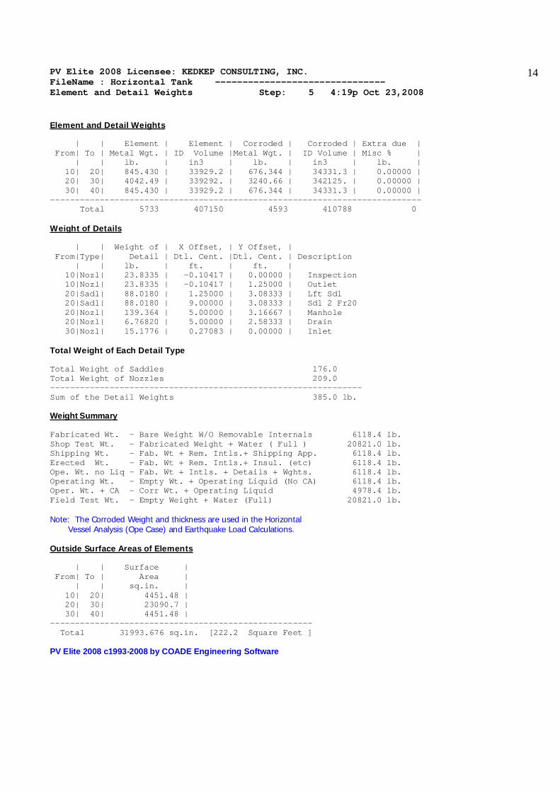
Element and Detail Weights | | Element | Element | Corroded | Corroded | Extra due | From| To | Metal Wgt. | ID Volume |Metal Wgt. | ID Volume | Misc % | | | lb. | in3 | lb. | in3 | lb. | 10| 20| 845.430 | 33929.2 | 676.344 | 34331.3 | 0.00000 | 20| 30| 4042.49 | 339292. | 3240.66 | 342125. | 0.00000 | 30| 40| 845.430 | 33929.2 | 676.344 | 34331.3 | 0.00000 | --------------------------------------------------------------------------- Total 5733 407150 4593 410788 0 Weight of Details | | Weight of | X Offset, | Y Offset, | From|Type| Detail | Dtl. Cent. |Dtl. Cent. | Description | | lb. | ft. | ft. | 10|Nozl| 23.8335 | -0.10417 | 0.00000 | Inspection 10|Nozl| 23.8335 | -0.10417 | 1.25000 | Outlet 20|Sadl| 88.0180 | 1.25000 | 3.08333 | Lft Sdl 20|Sadl| 88.0180 | 9.00000 | 3.08333 | Sdl 2 Fr20 20|Nozl| 139.364 | 5.00000 | 3.16667 | Manhole 20|Nozl| 6.76820 | 5.00000 | 2.58333 | Drain 30|Nozl| 15.1776 | 0.27083 | 0.00000 | Inlet Total Weight of Each Detail Type Total Weight of Saddles 176.0 Total Weight of Nozzles 209.0 --------------------------------------------------------------- Sum of the Detail Weights 385.0 lb. Weight Summary Fabricated Wt. - Bare Weight W/O Removable Internals 6118.4 lb. Shop Test Wt. - Fabricated Weight + Water ( Full ) 20821.0 lb. Shipping Wt. - Fab. Wt + Rem. Intls.+ Shipping App. 6118.4 lb. Erected Wt. - Fab. Wt + Rem. Intls.+ Insul. (etc) 6118.4 lb. Ope. Wt. no Liq - Fab. Wt + Intls. + Details + Wghts. 6118.4 lb. Operating Wt. - Empty Wt. + Operating Liquid (No CA) 6118.4 lb. Oper. Wt. + CA - Corr Wt. + Operating Liquid 4978.4 lb. Field Test Wt. - Empty Weight + Water (Full) 20821.0 lb. Note: The Corroded Weight and thickness are used in the Horizontal Vessel Analysis (Ope Case) and Earthquake Load Calculations. Outside Surface Areas of Elements | | Surface | From| To | Area | | | sq.in. | 10| 20| 4451.48 | 20| 30| 23090.7 | 30| 40| 4451.48 | ----------------------------------------------------- Total 31993.676 sq.in. [222.2 Square Feet ] PV Elite 2008 c1993-2008 by COADE Engineering Software

PV Elite 2008 Licensee: KEDKEP CONSULTING, INC. FileName : Horizontal Tank ------------------------------- Nozzle Flange MAWP Step: 6 4:19p Oct 23,2008
15
Nozzle Flange MAWP Results : Flange Rating Operating Ambient Temperature Class Grade|Group psig psig F ---------------------------------------------------------------------------- 260.000 285.000 200 150 GR 1.1 ---------------------------------------------------------------------------- Minimum Rating 260.000 285.000 psig Note: ANSI Ratings are per ANSI/ASME B16.5 2003 Edition PV Elite 2008 c1993-2008 by COADE Engineering Software
PV Elite 2008 Licensee: KEDKEP CONSULTING, INC. FileName : Horizontal Tank ------------------------------- Wind Load Calculation Step: 7 4:19p Oct 23,2008
16
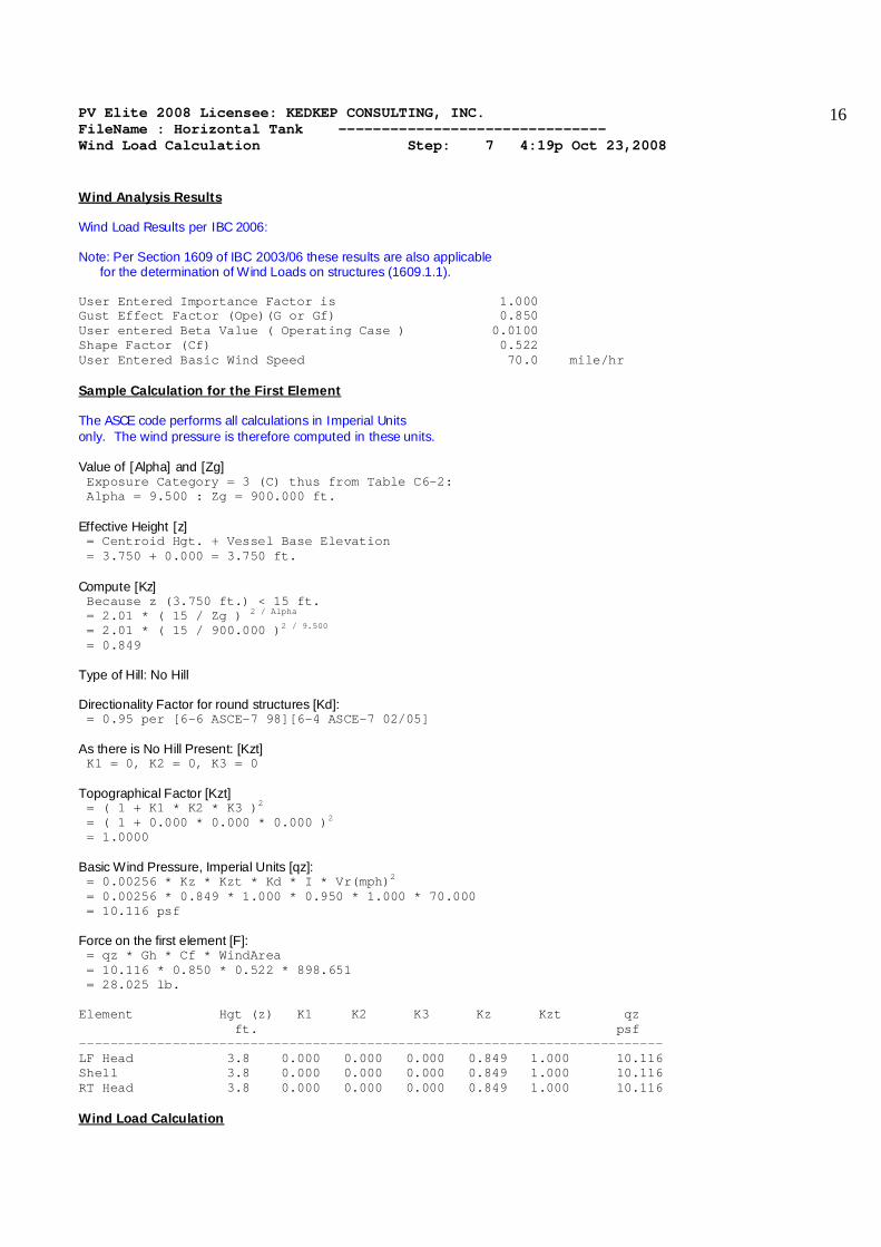
Wind Analysis Results Wind Load Results per IBC 2006: Note: Per Section 1609 of IBC 2003/06 these results are also applicable for the determination of Wind Loads on structures (1609.1.1). User Entered Importance Factor is 1.000 Gust Effect Factor (Ope)(G or Gf) 0.850 User entered Beta Value ( Operating Case ) 0.0100 Shape Factor (Cf) 0.522 User Entered Basic Wind Speed 70.0 mile/hr Sample Calculation for the First Element The ASCE code performs all calculations in Imperial Units only. The wind pressure is therefore computed in these units. Value of [Alpha] and [Zg] Exposure Category = 3 (C) thus from Table C6-2: Alpha = 9.500 : Zg = 900.000 ft. Effective Height [z] = Centroid Hgt. + Vessel Base Elevation = 3.750 + 0.000 = 3.750 ft. Compute [Kz] Because z (3.750 ft.) < 15 ft. = 2.01 * ( 15 / Zg ) 2 / Alpha = 2.01 * ( 15 / 900.000 )2 / 9.500 = 0.849 Type of Hill: No Hill Directionality Factor for round structures [Kd]: = 0.95 per [6-6 ASCE-7 98][6-4 ASCE-7 02/05] As there is No Hill Present: [Kzt] K1 = 0, K2 = 0, K3 = 0 Topographical Factor [Kzt] = ( 1 + K1 * K2 * K3 )2 = ( 1 + 0.000 * 0.000 * 0.000 )2 = 1.0000 Basic Wind Pressure, Imperial Units [qz]: = 0.00256 * Kz * Kzt * Kd * I * Vr(mph)2 = 0.00256 * 0.849 * 1.000 * 0.950 * 1.000 * 70.000 = 10.116 psf Force on the first element [F]: = qz * Gh * Cf * WindArea = 10.116 * 0.850 * 0.522 * 898.651 = 28.025 lb. Element Hgt (z) K1 K2 K3 Kz Kzt qz ft. psf --------------------------------------------------------------------------- LF Head 3.8 0.000 0.000 0.000 0.849 1.000 10.116 Shell 3.8 0.000 0.000 0.000 0.849 1.000 10.116 RT Head 3.8 0.000 0.000 0.000 0.849 1.000 10.116 Wind Load Calculation

PV Elite 2008 Licensee: KEDKEP CONSULTING, INC. FileName : Horizontal Tank ------------------------------- Wind Load Calculation Step: 7 4:19p Oct 23,2008
17
| | Wind | Wind | Wind | Height | Element | From| To | Height | Diameter | Area | Factor | Wind Load | | | ft. | ft. | sq.in. | psf | lb. | 10| 20| 3.75000 | 6.12500 | 898.651 | 10.1160 | 28.0249 | 20| 30| 3.75000 | 6.12500 | 8820.00 | 10.1160 | 275.056 | 30| 40| 3.75000 | 6.12500 | 898.651 | 10.1160 | 28.0249 | PV Elite 2008 c1993-2008 by COADE Engineering Software

PV Elite 2008 Licensee: KEDKEP CONSULTING, INC. FileName : Horizontal Tank ------------------------------- Earthquake Load Calculation Step: 8 4:19p Oct 23,2008
18
Earthquake Analysis Results per ASCE 7-2002/IBC 2003/06 User Entered Table Value 9.4.1.2.4a Fa: 1.000 User Entered Table Value 9.4.1.2.4b Fv: 1.400 Max. Mapped Acceleration Value for Short Periods Ss: 1.000 Max. Mapped Acceleration Value for 1 Sec. Period S1: 0.400 Force Modification Factor R: 3.000 Importance Factor I: 1.000 Site Class C Sms = Fa * Ss = 1.000 * 1.000 = 1.000 Sm1 = Fv * S1 = 1.400 * 0.400 = 0.560 Sds = 2/3 * Sms = 2/3 * 1.000 = 0.667 Sd1 = 2/3 * Sm1 = 2/3 * 0.560 = 0.373 Check the Period (1/Frequency) from 9.5.5.3.2-1 [T]: = Ct * hnx where Ct = 0.020, x = 0.75 and hn = total Vessel Height = 0.020 * ( 5.0000 0.75) = 0.067 seconds The Coefficient Cu from Table 9.5.5.3.1 is : 1.400 Check the Min. Value of T which is the Smaller of Cu*Ta and T [T]: = Minimum Value of (1.400 * 0.067 , 1/33.000 ) = 0.0303 per 9.5.5.3 As the time period is < 0.06 second, use section 9.14.5.2. Compute the Base Shear per 9.14.5.2, [V]: = 0.3 * Sds * W * I = 0.3 * 0.667 * 4978 * 1.00 = 995.67 lb. Note: Loads multiplied by the Scalar multiplier value of 0.7000 Final Base Shear, V = 696.97 lb. Earthquake Load Calculation | | Earthquake | Earthquake | Element | From| To | Height | Weight | Ope Load | | | ft. | lb. | lb. | 10| 20| 2.50000 | 995.672 | 139.394 | 20|Sadl| 2.50000 | 995.672 | 139.394 | Sadl| 30| 2.50000 | 995.672 | 139.394 | 20| 30| 2.50000 | 995.672 | 139.394 | 30| 40| 2.50000 | 995.672 | 139.394 | PV Elite 2008 c1993-2008 by COADE Engineering Software

PV Elite 2008 Licensee: KEDKEP CONSULTING, INC. FileName : Horizontal Tank ------------------------------- Center of Gravity Calculation Step: 9 4:19p Oct 23,2008
19
Shop/Field Installation Options : Note : The CG is computed from the first Element From Node Center of Gravity of Saddles 5.3 ft. Center of Gravity of Nozzles 4.3 ft. Center of Gravity of Bare Shell New and Cold 5.2 ft. Center of Gravity of Bare Shell Corroded 5.2 ft. Vessel CG in the Operating Condition 5.1 ft. Vessel CG in the Fabricated (Shop/Empty) Condition 5.1 ft. PV Elite 2008 c1993-2008 by COADE Engineering Software
PV Elite 2008 Licensee: KEDKEP CONSULTING, INC. FileName : Horizontal Tank ------------------------------- Horizontal Vessel Analysis (Ope.) Step: 10 4:19p Oct 23,2008
20
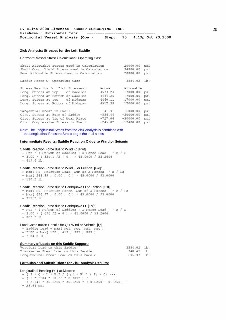
Zick Analysis: Stresses for the Left Saddle Horizontal Vessel Stress Calculations : Operating Case Shell Allowable Stress used in Calculation 20000.00 psi Shell Comp. Yield Stress used in Calculation 34800.00 psi Head Allowable Stress used in Calculation 20000.00 psi Saddle Force Q, Operating Case 3384.02 lb. Stress Results for Zick Stresses: Actual Allowable Long. Stress at Top of Saddles 4533.24 17000.00 psi Long. Stress at Bottom of Saddles 4444.26 17000.00 psi Long. Stress at Top of Midspan 4460.11 17000.00 psi Long. Stress at Bottom of Midspan 4517.39 17000.00 psi Tangential Shear in Shell 141.91 16000.00 psi Circ. Stress at Horn of Saddle -836.44 -30000.00 psi Circ. Stress at Tip of Wear Plate -727.06 -30000.00 psi Circ. Compressive Stress in Shell -245.02 -17400.00 psi Note: The Longitudinal Stress from the Zick Analysis is combined with the Longitudinal Pressure Stress to get the total stress. Intermediate Results: Saddle Reaction Q due to Wind or Seismic Saddle Reaction Force due to Wind Ft [Fwt]: = Ftr * ( Ft/Num of Saddles + Z Force Load ) * B / E = 3.00 * ( 331.1 /2 + 0 ) * 45.0000 / 53.2606 = 419.6 lb. Saddle Reaction Force due to Wind Fl or Friction [Fwl]: = Max( Fl, Friction Load, Sum of X Forces) * B / Ls = Max( 248.39 , 0.00 , 0 ) * 45.0000 / 93.0000 = 120.2 lb. Saddle Reaction Force due to Earthquake Fl or Friction [Fsl]: = Max( Fl, Friction Force, Sum of X Forces ) * B / Ls = Max( 696.97 , 0.00 , 0 ) * 45.0000 / 93.0000 = 337.2 lb. Saddle Reaction Force due to Earthquake Ft [Fst]: = Ftr * ( Ft/Num of Saddles + Z Force Load ) * B / E = 3.00 * ( 696 /2 + 0 ) * 45.0000 / 53.2606 = 883.3 lb. Load Combination Results for Q + Wind or Seismic [Q]: = Saddle Load + Max( Fwl, Fwt, Fsl, Fst ) = 2500 + Max( 120 , 419 , 337 , 883 ) = 3384.0 lb. Summary of Loads on this Saddle Support: Vertical Load on this Saddle 3384.02 lb. Transverse Shear Load on this Saddle 348.49 lb. Longitudinal Shear Load on this Saddle 696.97 lb. Formulas and Substitutions for Zick Analysis Results: Longitudinal Bending (+-) at Midspan = ( 3 * Q * L * K.2 / ( pi * R2 * ( Ts - Ca ))) = ( 3 * 3384 * 10.33 * 0.3892 ) / ( 3.141 * 30.1250 * 30.1250 * ( 0.6250 - 0.1250 ))) = 28.64 psi
PV Elite 2008 Licensee: KEDKEP CONSULTING, INC. FileName : Horizontal Tank ------------------------------- Horizontal Vessel Analysis (Ope.) Step: 10 4:19p Oct 23,2008
21
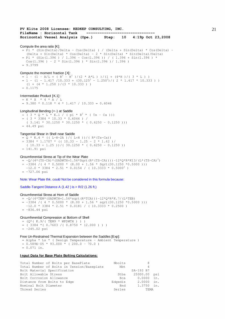
Compute the area ratio [K]: = Pi * (Sin(Delta)/Delta - Cos(Delta) ) / (Delta + Sin(Delta) * Cos(Delta) - (Delta + Sin(Delta) * Cos(Delta) - 2 * Sin(Delta) * Sin(Delta)/Delta) = Pi * (Sin(1.396 ) / 1.396 - Cos(1.396 )) / ( 1.396 + Sin(1.396 ) * Cos(1.396 ) - 2 * Sin(1.396 ) * Sin(1.396 )/ 1.396 ) = 9.3799 Compute the moment fraction [X]: = 1 - (1 - A/L + ( R2 - H2 )/(2 * A*L ) )/(1 + (4*H )/( 3 * L ) ) = 1 - (1 - 1.417 /10.333 + (30.1252 - 1.2502)/( 2 * 1.417 * 10.333 ) ) (1 + (4 * 1.250 )/(3 * 10.333 ) ) = 0.1175 Intermediate Product [K.1]: = K * X * 4 * A / L = 9.380 * 0.118 * 4 * 1.417 / 10.333 = 0.6046 Longitudinal Bending (+-) at Saddle = ( 3 * Q * L * K.1 / ( pi * R2 * ( Ts - Ca ))) = ( 3 * 3384 * 10.33 * 0.6046 ) / ( 3.141 * 30.1250 * 30.1250 * ( 0.6250 - 0.1250 ))) = 44.49 psi Tangential Shear in Shell near Saddle = Q * K.4 * (( L-H-2A )/( L+H ))/( R*(Ts-Ca)) = 3384 * 1.1707 * (( 10.33 - 1.25 - 2 * 1.42 )/ ( 10.33 + 1.25 ))/( 30.1250 * ( 0.6250 - 0.1250 )) = 141.91 psi Circumferential Stress at Tip of the Wear Plate = -Q/(4*(TS-CA)*(SADWTH+1.56*Sqrt(R*(TS-CA))))-12*Q*R*K13/(L*(TS-CA)2) = -3384 /( 4 * 0.5000 * (8.00 + 1.56 * Sqrt(30.1250 *0.5000 ))) -12.0 * 3384 * 2.51 * 0.0154 / ( 10.3333 * 0.50002 ) = -727.06 psi Note: Wear Plate thk. could Not be considered in this formula because: Saddle-Tangent Distance A (1.42 ) is > R/2 (1.26 ft.) Circumferential Stress at Horn of Saddle = -Q/(4*TEM*(SADWTH+1.56*sqrt(R*TCA)))-12*Q*R*K.7/(L*TEB) = -3384 /( 4 * 0.5000 * (8.00 + 1.56 * sqrt(30.1250 *0.5000 ))) -12.0 * 3384 * 2.51 * 0.0181 / ( 10.3333 * 0.2500 ) = -836.44 psi Circumferential Compression at Bottom of Shell = (Q*( K.9/( TEM9 * WPDWTH ) ) ) = ( 3384 *( 0.7603 /( 0.8750 * 12.000 ) ) ) = -245.02 psi Free Un-Restrained Thermal Expansion between the Saddles [Exp]: = Alpha * Ls * ( Design Temperature - Ambient Temperature ) = 0.589E-05 * 93.000 * ( 200.0 - 70.0 ) = 0.071 in. Input Data for Base Plate Bolting Calculations: Total Number of Bolts per BasePlate Nbolts 8 Total Number of Bolts in Tension/Baseplate Nbt 4 Bolt Material Specification SA-193 B7 Bolt Allowable Stress Stba 25000.00 psi Bolt Corrosion Allowance Bca 0.0000 in. Distance from Bolts to Edge Edgedis 2.0000 in. Nominal Bolt Diameter Bnd 1.3750 in. Thread Series Series TEMA
PV Elite 2008 Licensee: KEDKEP CONSULTING, INC. FileName : Horizontal Tank ------------------------------- Horizontal Vessel Analysis (Ope.) Step: 10 4:19p Oct 23,2008
22
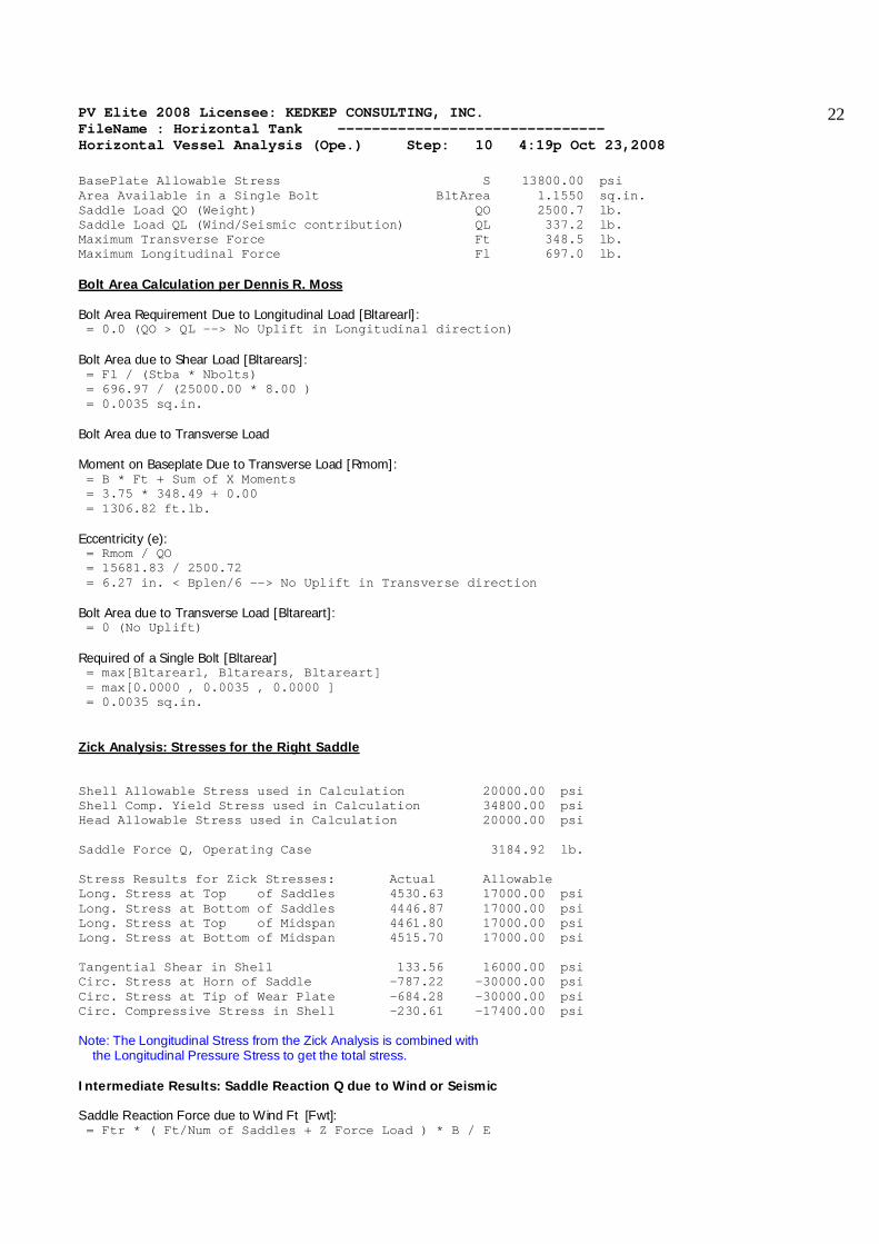
BasePlate Allowable Stress S 13800.00 psi Area Available in a Single Bolt BltArea 1.1550 sq.in. Saddle Load QO (Weight) QO 2500.7 lb. Saddle Load QL (Wind/Seismic contribution) QL 337.2 lb. Maximum Transverse Force Ft 348.5 lb. Maximum Longitudinal Force Fl 697.0 lb. Bolt Area Calculation per Dennis R. Moss Bolt Area Requirement Due to Longitudinal Load [Bltarearl]: = 0.0 (QO > QL --> No Uplift in Longitudinal direction) Bolt Area due to Shear Load [Bltarears]: = Fl / (Stba * Nbolts) = 696.97 / (25000.00 * 8.00 ) = 0.0035 sq.in. Bolt Area due to Transverse Load Moment on Baseplate Due to Transverse Load [Rmom]: = B * Ft + Sum of X Moments = 3.75 * 348.49 + 0.00 = 1306.82 ft.lb. Eccentricity (e): = Rmom / QO = 15681.83 / 2500.72 = 6.27 in. < Bplen/6 --> No Uplift in Transverse direction Bolt Area due to Transverse Load [Bltareart]: = 0 (No Uplift) Required of a Single Bolt [Bltarear] = max[Bltarearl, Bltarears, Bltareart] = max[0.0000 , 0.0035 , 0.0000 ] = 0.0035 sq.in. Zick Analysis: Stresses for the Right Saddle Shell Allowable Stress used in Calculation 20000.00 psi Shell Comp. Yield Stress used in Calculation 34800.00 psi Head Allowable Stress used in Calculation 20000.00 psi Saddle Force Q, Operating Case 3184.92 lb. Stress Results for Zick Stresses: Actual Allowable Long. Stress at Top of Saddles 4530.63 17000.00 psi Long. Stress at Bottom of Saddles 4446.87 17000.00 psi Long. Stress at Top of Midspan 4461.80 17000.00 psi Long. Stress at Bottom of Midspan 4515.70 17000.00 psi Tangential Shear in Shell 133.56 16000.00 psi Circ. Stress at Horn of Saddle -787.22 -30000.00 psi Circ. Stress at Tip of Wear Plate -684.28 -30000.00 psi Circ. Compressive Stress in Shell -230.61 -17400.00 psi Note: The Longitudinal Stress from the Zick Analysis is combined with the Longitudinal Pressure Stress to get the total stress. Intermediate Results: Saddle Reaction Q due to Wind or Seismic Saddle Reaction Force due to Wind Ft [Fwt]: = Ftr * ( Ft/Num of Saddles + Z Force Load ) * B / E

PV Elite 2008 Licensee: KEDKEP CONSULTING, INC. FileName : Horizontal Tank ------------------------------- Horizontal Vessel Analysis (Ope.) Step: 10 4:19p Oct 23,2008
23
= 3.00 * ( 331.1 /2 + 0 ) * 45.0000 / 53.2606 = 419.6 lb. Saddle Reaction Force due to Wind Fl or Friction [Fwl]: = Max( Fl, Friction Load, Sum of X Forces) * B / Ls = Max( 248.39 , 0.00 , 0 ) * 45.0000 / 93.0000 = 120.2 lb. Saddle Reaction Force due to Earthquake Fl or Friction [Fsl]: = Max( Fl, Friction Force, Sum of X Forces ) * B / Ls = Max( 696.97 , 0.00 , 0 ) * 45.0000 / 93.0000 = 337.2 lb. Saddle Reaction Force due to Earthquake Ft [Fst]: = Ftr * ( Ft/Num of Saddles + Z Force Load ) * B / E = 3.00 * ( 696 /2 + 0 ) * 45.0000 / 53.2606 = 883.3 lb. Load Combination Results for Q + Wind or Seismic [Q]: = Saddle Load + Max( Fwl, Fwt, Fsl, Fst ) = 2301 + Max( 120 , 419 , 337 , 883 ) = 3184.9 lb. Summary of Loads on this Saddle Support: Vertical Load on this Saddle 3184.92 lb. Transverse Shear Load on this Saddle 348.49 lb. Longitudinal Shear Load on this Saddle 696.97 lb. Formulas and Substitutions for Zick Analysis Results: Longitudinal Bending (+-) at Midspan = ( 3 * Q * L * K.2 / ( pi * R2 * ( Ts - Ca ))) = ( 3 * 3184 * 10.33 * 0.3892 ) / ( 3.141 * 30.1250 * 30.1250 * ( 0.6250 - 0.1250 ))) = 26.95 psi Compute the area ratio [K]: = Pi * (Sin(Delta)/Delta - Cos(Delta) ) / (Delta + Sin(Delta) * Cos(Delta) - (Delta + Sin(Delta) * Cos(Delta) - 2 * Sin(Delta) * Sin(Delta)/Delta) = Pi * (Sin(1.396 ) / 1.396 - Cos(1.396 )) / ( 1.396 + Sin(1.396 ) * Cos(1.396 ) - 2 * Sin(1.396 ) * Sin(1.396 )/ 1.396 ) = 9.3799 Compute the moment fraction [X]: = 1 - (1 - A/L + ( R2 - H2 )/(2 * A*L ) )/(1 + (4*H )/( 3 * L ) ) = 1 - (1 - 1.417 /10.333 + (30.1252 - 1.2502)/( 2 * 1.417 * 10.333 ) ) (1 + (4 * 1.250 )/(3 * 10.333 ) ) = 0.1175 Intermediate Product [K.1]: = K * X * 4 * A / L = 9.380 * 0.118 * 4 * 1.417 / 10.333 = 0.6046 Longitudinal Bending (+-) at Saddle = ( 3 * Q * L * K.1 / ( pi * R2 * ( Ts - Ca ))) = ( 3 * 3184 * 10.33 * 0.6046 ) / ( 3.141 * 30.1250 * 30.1250 * ( 0.6250 - 0.1250 ))) = 41.88 psi Tangential Shear in Shell near Saddle = Q * K.4 * (( L-H-2A )/( L+H ))/( R*(Ts-Ca)) = 3184 * 1.1707 * (( 10.33 - 1.25 - 2 * 1.42 )/ ( 10.33 + 1.25 ))/( 30.1250 * ( 0.6250 - 0.1250 )) = 133.56 psi

PV Elite 2008 Licensee: KEDKEP CONSULTING, INC. FileName : Horizontal Tank ------------------------------- Horizontal Vessel Analysis (Ope.) Step: 10 4:19p Oct 23,2008
24
Circumferential Stress at Tip of the Wear Plate = -Q/(4*(TS-CA)*(SADWTH+1.56*Sqrt(R*(TS-CA))))-12*Q*R*K13/(L*(TS-CA)2) = -3184 /( 4 * 0.5000 * (8.00 + 1.56 * Sqrt(30.1250 *0.5000 ))) -12.0 * 3184 * 2.51 * 0.0154 / ( 10.3333 * 0.50002 ) = -684.28 psi Note: Wear Plate thk. could Not be considered in this formula because: Saddle-Tangent Distance A (1.42 ) is > R/2 (1.26 ft.) Circumferential Stress at Horn of Saddle = -Q/(4*TEM*(SADWTH+1.56*sqrt(R*TCA)))-12*Q*R*K.7/(L*TEB) = -3184 /( 4 * 0.5000 * (8.00 + 1.56 * sqrt(30.1250 *0.5000 ))) -12.0 * 3184 * 2.51 * 0.0181 / ( 10.3333 * 0.2500 ) = -787.22 psi Circumferential Compression at Bottom of Shell = (Q*( K.9/( TEM9 * WPDWTH ) ) ) = ( 3184 *( 0.7603 /( 0.8750 * 12.000 ) ) ) = -230.61 psi PV Elite 2008 c1993-2008 by COADE Engineering Software
PV Elite 2008 Licensee: KEDKEP CONSULTING, INC. FileName : Horizontal Tank ------------------------------- Horizontal Vessel Analysis (Test) Step: 11 4:19p Oct 23,2008
25
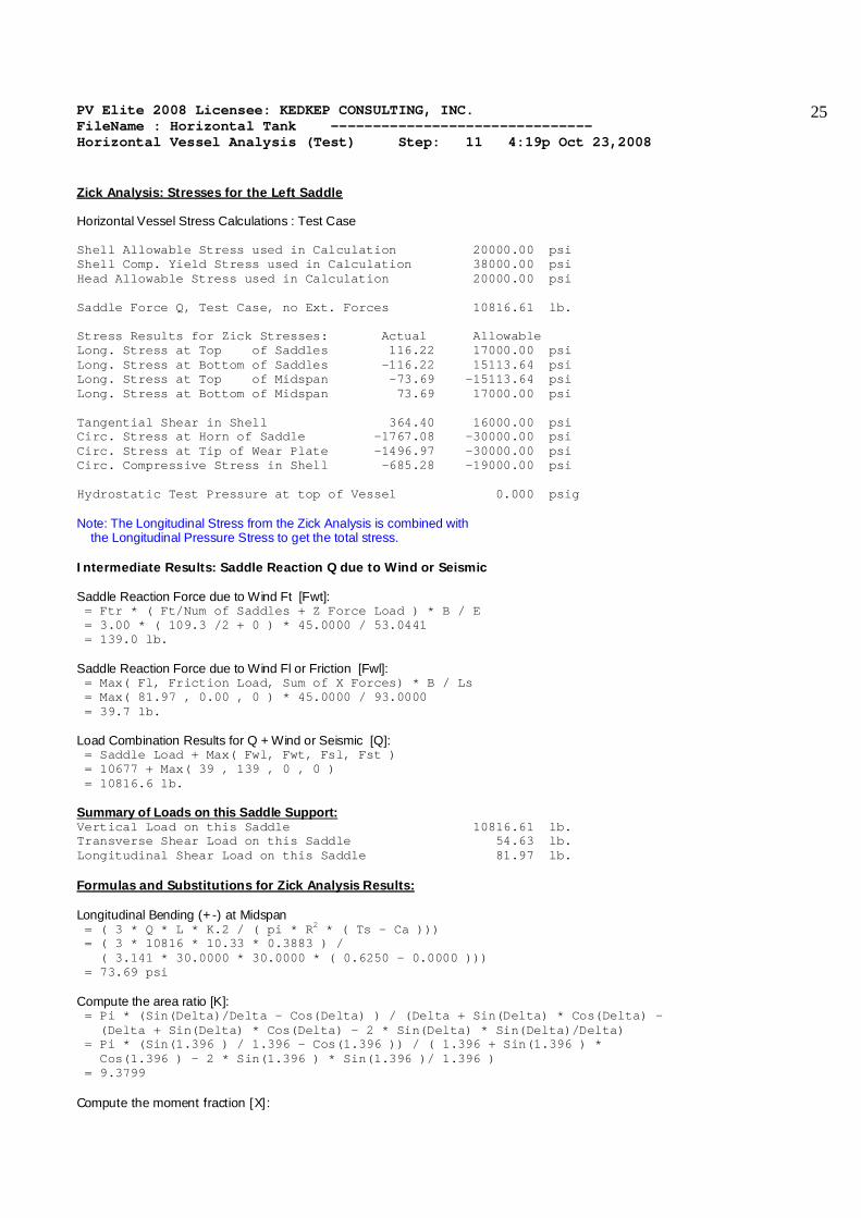
Zick Analysis: Stresses for the Left Saddle Horizontal Vessel Stress Calculations : Test Case Shell Allowable Stress used in Calculation 20000.00 psi Shell Comp. Yield Stress used in Calculation 38000.00 psi Head Allowable Stress used in Calculation 20000.00 psi Saddle Force Q, Test Case, no Ext. Forces 10816.61 lb. Stress Results for Zick Stresses: Actual Allowable Long. Stress at Top of Saddles 116.22 17000.00 psi Long. Stress at Bottom of Saddles -116.22 15113.64 psi Long. Stress at Top of Midspan -73.69 -15113.64 psi Long. Stress at Bottom of Midspan 73.69 17000.00 psi Tangential Shear in Shell 364.40 16000.00 psi Circ. Stress at Horn of Saddle -1767.08 -30000.00 psi Circ. Stress at Tip of Wear Plate -1496.97 -30000.00 psi Circ. Compressive Stress in Shell -685.28 -19000.00 psi Hydrostatic Test Pressure at top of Vessel 0.000 psig Note: The Longitudinal Stress from the Zick Analysis is combined with the Longitudinal Pressure Stress to get the total stress. Intermediate Results: Saddle Reaction Q due to Wind or Seismic Saddle Reaction Force due to Wind Ft [Fwt]: = Ftr * ( Ft/Num of Saddles + Z Force Load ) * B / E = 3.00 * ( 109.3 /2 + 0 ) * 45.0000 / 53.0441 = 139.0 lb. Saddle Reaction Force due to Wind Fl or Friction [Fwl]: = Max( Fl, Friction Load, Sum of X Forces) * B / Ls = Max( 81.97 , 0.00 , 0 ) * 45.0000 / 93.0000 = 39.7 lb. Load Combination Results for Q + Wind or Seismic [Q]: = Saddle Load + Max( Fwl, Fwt, Fsl, Fst ) = 10677 + Max( 39 , 139 , 0 , 0 ) = 10816.6 lb. Summary of Loads on this Saddle Support: Vertical Load on this Saddle 10816.61 lb. Transverse Shear Load on this Saddle 54.63 lb. Longitudinal Shear Load on this Saddle 81.97 lb. Formulas and Substitutions for Zick Analysis Results: Longitudinal Bending (+-) at Midspan = ( 3 * Q * L * K.2 / ( pi * R2 * ( Ts - Ca ))) = ( 3 * 10816 * 10.33 * 0.3883 ) / ( 3.141 * 30.0000 * 30.0000 * ( 0.6250 - 0.0000 ))) = 73.69 psi Compute the area ratio [K]: = Pi * (Sin(Delta)/Delta - Cos(Delta) ) / (Delta + Sin(Delta) * Cos(Delta) - (Delta + Sin(Delta) * Cos(Delta) - 2 * Sin(Delta) * Sin(Delta)/Delta) = Pi * (Sin(1.396 ) / 1.396 - Cos(1.396 )) / ( 1.396 + Sin(1.396 ) * Cos(1.396 ) - 2 * Sin(1.396 ) * Sin(1.396 )/ 1.396 ) = 9.3799 Compute the moment fraction [X]:
PV Elite 2008 Licensee: KEDKEP CONSULTING, INC. FileName : Horizontal Tank ------------------------------- Horizontal Vessel Analysis (Test) Step: 11 4:19p Oct 23,2008
26
= 1 - (1 - A/L + ( R2 - H2 )/(2 * A*L ) )/(1 + (4*H )/( 3 * L ) ) = 1 - (1 - 1.417 /10.333 + (30.0002 - 1.2502)/( 2 * 1.417 * 10.333 ) ) (1 + (4 * 1.250 )/(3 * 10.333 ) ) = 0.1191 Intermediate Product [K.1]: = K * X * 4 * A / L = 9.380 * 0.119 * 4 * 1.417 / 10.333 = 0.6125 Longitudinal Bending (+-) at Saddle = ( 3 * Q * L * K.1 / ( pi * R2 * ( Ts - Ca ))) = ( 3 * 10816 * 10.33 * 0.6125 ) / ( 3.141 * 30.0000 * 30.0000 * ( 0.6250 - 0.0000 ))) = 116.22 psi Tangential Shear in Shell near Saddle = Q * K.4 * (( L-H-2A )/( L+H ))/( R*(Ts-Ca)) = 10816 * 1.1707 * (( 10.33 - 1.25 - 2 * 1.42 )/ ( 10.33 + 1.25 ))/( 30.0000 * ( 0.6250 - 0.0000 )) = 364.40 psi Circumferential Stress at Tip of the Wear Plate = -Q/(4*(TS-CA)*(SADWTH+1.56*Sqrt(R*(TS-CA))))-12*Q*R*K13/(L*(TS-CA)2) = -10816 /( 4 * 0.6250 * (8.00 + 1.56 * Sqrt(30.0000 *0.6250 ))) -12.0 * 10816 * 2.50 * 0.0150 / ( 10.3333 * 0.62502 ) = -1496.97 psi Note: Wear Plate thk. could Not be considered in this formula because: Saddle-Tangent Distance A (1.42 ) is > R/2 (1.25 ft.) Circumferential Stress at Horn of Saddle = -Q/(4*TEM*(SADWTH+1.56*sqrt(R*TCA)))-12*Q*R*K.7/(L*TEB) = -10816 /( 4 * 0.6250 * (8.00 + 1.56 * sqrt(30.0000 *0.6250 ))) -12.0 * 10816 * 2.50 * 0.0183 / ( 10.3333 * 0.3906 ) = -1767.08 psi Circumferential Compression at Bottom of Shell = (Q*( K.9/( TEM9 * WPDWTH ) ) ) = ( 10816 *( 0.7603 /( 1.0000 * 12.000 ) ) ) = -685.28 psi Input Data for Base Plate Bolting Calculations: Total Number of Bolts per BasePlate Nbolts 8 Total Number of Bolts in Tension/Baseplate Nbt 4 Bolt Material Specification SA-193 B7 Bolt Allowable Stress Stba 25000.00 psi Bolt Corrosion Allowance Bca 0.0000 in. Distance from Bolts to Edge Edgedis 2.0000 in. Nominal Bolt Diameter Bnd 1.3750 in. Thread Series Series TEMA BasePlate Allowable Stress S 13800.00 psi Area Available in a Single Bolt BltArea 1.1550 sq.in. Saddle Load QO (Weight) QO 10677.6 lb. Saddle Load QL (Wind/Seismic contribution) QL 39.7 lb. Maximum Transverse Force Ft 54.6 lb. Maximum Longitudinal Force Fl 82.0 lb. Bolt Area Calculation per Dennis R. Moss Bolt Area Requirement Due to Longitudinal Load [Bltarearl]: = 0.0 (QO > QL --> No Uplift in Longitudinal direction) Bolt Area due to Shear Load [Bltarears]:
PV Elite 2008 Licensee: KEDKEP CONSULTING, INC. FileName : Horizontal Tank ------------------------------- Horizontal Vessel Analysis (Test) Step: 11 4:19p Oct 23,2008
27
= Fl / (Stba * Nbolts) = 81.97 / (25000.00 * 8.00 ) = 0.0004 sq.in. Bolt Area due to Transverse Load Moment on Baseplate Due to Transverse Load [Rmom]: = B * Ft + Sum of X Moments = 3.75 * 54.63 + 0.00 = 204.87 ft.lb. Eccentricity (e): = Rmom / QO = 2458.46 / 10677.57 = 0.23 in. < Bplen/6 --> No Uplift in Transverse direction Bolt Area due to Transverse Load [Bltareart]: = 0 (No Uplift) Required of a Single Bolt [Bltarear] = max[Bltarearl, Bltarears, Bltareart] = max[0.0000 , 0.0004 , 0.0000 ] = 0.0004 sq.in. Zick Analysis: Stresses for the Right Saddle Shell Allowable Stress used in Calculation 20000.00 psi Shell Comp. Yield Stress used in Calculation 38000.00 psi Head Allowable Stress used in Calculation 20000.00 psi Saddle Force Q, Test Case, no Ext. Forces 10106.45 lb. Stress Results for Zick Stresses: Actual Allowable Long. Stress at Top of Saddles 108.59 17000.00 psi Long. Stress at Bottom of Saddles -108.59 15113.64 psi Long. Stress at Top of Midspan -68.85 -15113.64 psi Long. Stress at Bottom of Midspan 68.85 17000.00 psi Tangential Shear in Shell 340.48 16000.00 psi Circ. Stress at Horn of Saddle -1651.07 -30000.00 psi Circ. Stress at Tip of Wear Plate -1398.68 -30000.00 psi Circ. Compressive Stress in Shell -640.29 -19000.00 psi Hydrostatic Test Pressure at top of Vessel 0.000 psig Note: The Longitudinal Stress from the Zick Analysis is combined with the Longitudinal Pressure Stress to get the total stress. Intermediate Results: Saddle Reaction Q due to Wind or Seismic Saddle Reaction Force due to Wind Ft [Fwt]: = Ftr * ( Ft/Num of Saddles + Z Force Load ) * B / E = 3.00 * ( 109.3 /2 + 0 ) * 45.0000 / 53.0441 = 139.0 lb. Saddle Reaction Force due to Wind Fl or Friction [Fwl]: = Max( Fl, Friction Load, Sum of X Forces) * B / Ls = Max( 81.97 , 0.00 , 0 ) * 45.0000 / 93.0000 = 39.7 lb. Load Combination Results for Q + Wind or Seismic [Q]: = Saddle Load + Max( Fwl, Fwt, Fsl, Fst ) = 9967 + Max( 39 , 139 , 0 , 0 )
PV Elite 2008 Licensee: KEDKEP CONSULTING, INC. FileName : Horizontal Tank ------------------------------- Horizontal Vessel Analysis (Test) Step: 11 4:19p Oct 23,2008
28
= 10106.5 lb. Summary of Loads on this Saddle Support: Vertical Load on this Saddle 10106.45 lb. Transverse Shear Load on this Saddle 54.63 lb. Longitudinal Shear Load on this Saddle 81.97 lb. Formulas and Substitutions for Zick Analysis Results: Longitudinal Bending (+-) at Midspan = ( 3 * Q * L * K.2 / ( pi * R2 * ( Ts - Ca ))) = ( 3 * 10106 * 10.33 * 0.3883 ) / ( 3.141 * 30.0000 * 30.0000 * ( 0.6250 - 0.0000 ))) = 68.85 psi Compute the area ratio [K]: = Pi * (Sin(Delta)/Delta - Cos(Delta) ) / (Delta + Sin(Delta) * Cos(Delta) - (Delta + Sin(Delta) * Cos(Delta) - 2 * Sin(Delta) * Sin(Delta)/Delta) = Pi * (Sin(1.396 ) / 1.396 - Cos(1.396 )) / ( 1.396 + Sin(1.396 ) * Cos(1.396 ) - 2 * Sin(1.396 ) * Sin(1.396 )/ 1.396 ) = 9.3799 Compute the moment fraction [X]: = 1 - (1 - A/L + ( R2 - H2 )/(2 * A*L ) )/(1 + (4*H )/( 3 * L ) ) = 1 - (1 - 1.417 /10.333 + (30.0002 - 1.2502)/( 2 * 1.417 * 10.333 ) ) (1 + (4 * 1.250 )/(3 * 10.333 ) ) = 0.1191 Intermediate Product [K.1]: = K * X * 4 * A / L = 9.380 * 0.119 * 4 * 1.417 / 10.333 = 0.6125 Longitudinal Bending (+-) at Saddle = ( 3 * Q * L * K.1 / ( pi * R2 * ( Ts - Ca ))) = ( 3 * 10106 * 10.33 * 0.6125 ) / ( 3.141 * 30.0000 * 30.0000 * ( 0.6250 - 0.0000 ))) = 108.59 psi Tangential Shear in Shell near Saddle = Q * K.4 * (( L-H-2A )/( L+H ))/( R*(Ts-Ca)) = 10106 * 1.1707 * (( 10.33 - 1.25 - 2 * 1.42 )/ ( 10.33 + 1.25 ))/( 30.0000 * ( 0.6250 - 0.0000 )) = 340.48 psi Circumferential Stress at Tip of the Wear Plate = -Q/(4*(TS-CA)*(SADWTH+1.56*Sqrt(R*(TS-CA))))-12*Q*R*K13/(L*(TS-CA)2) = -10106 /( 4 * 0.6250 * (8.00 + 1.56 * Sqrt(30.0000 *0.6250 ))) -12.0 * 10106 * 2.50 * 0.0150 / ( 10.3333 * 0.62502 ) = -1398.68 psi Note: Wear Plate thk. could Not be considered in this formula because: Saddle-Tangent Distance A (1.42 ) is > R/2 (1.25 ft.) Circumferential Stress at Horn of Saddle = -Q/(4*TEM*(SADWTH+1.56*sqrt(R*TCA)))-12*Q*R*K.7/(L*TEB) = -10106 /( 4 * 0.6250 * (8.00 + 1.56 * sqrt(30.0000 *0.6250 ))) -12.0 * 10106 * 2.50 * 0.0183 / ( 10.3333 * 0.3906 ) = -1651.07 psi Circumferential Compression at Bottom of Shell = (Q*( K.9/( TEM9 * WPDWTH ) ) ) = ( 10106 *( 0.7603 /( 1.0000 * 12.000 ) ) ) = -640.29 psi
PV Elite 2008 Licensee: KEDKEP CONSULTING, INC. FileName : Horizontal Tank ------------------------------- Horizontal Vessel Analysis (Test) Step: 11 4:19p Oct 23,2008
29
PV Elite 2008 c1993-2008 by COADE Engineering Software

PV Elite 2008 Licensee: KEDKEP CONSULTING, INC. FileName : Horizontal Tank ------------------------------- Nozzle Calcs. Inspection Nozl: 1 4:19p Oct 23,2008
30
INPUT VALUES, Nozzle Description: Inspection From : 10 Pressure for Nozzle Reinforcement Calculations P 100.000 psig Temperature for Internal Pressure Temp 200 F Design External Pressure Pext 15.00 psig Temperature for External Pressure Tempex 200 F Shell Material SA-516 70 Shell Allowable Stress at Temperature S 20000.00 psi Shell Allowable Stress At Ambient Sa 20000.00 psi Inside Diameter of Elliptical Head D 60.0000 in. Aspect Ratio of Elliptical Head Ar 2.00 Head Actual Thickness T 0.6250 in. Head Internal Corrosion Allowance Cas 0.1250 in. Head External Corrosion Allowance Caext 0.0000 in. Distance from Head Centerline L1 0.0000 in. User Entered Minimum Design Metal Temperature -20.00 F Nozzle Material SA-106 B Nozzle Allowable Stress at Temperature Sn 17100.00 psi Nozzle Allowable Stress At Ambient Sna 17100.00 psi Nozzle Diameter Basis (for tr calc only) Inbase ID Layout Angle 0.00 deg Nozzle Diameter Dia 6.0000 in. Nozzle Size and Thickness Basis Idbn Nominal Nominal Thickness of Nozzle Thknom 80 Nozzle Flange Material SA-105 Nozzle Flange Type Weld Neck Flange Nozzle Corrosion Allowance Can 0.1250 in. Joint Efficiency of Shell Seam at Nozzle Es 1.00 Joint Efficiency of Nozzle Neck En 1.00 Nozzle Outside Projection Ho 2.0000 in. Weld leg size between Nozzle and Pad/Shell Wo 0.3750 in. Groove weld depth between Nozzle and Vessel Wgnv 0.6250 in. Nozzle Inside Projection H 0.0000 in. Weld leg size, Inside Nozzle to Shell Wi 0.0000 in. ASME Code Weld Type per UW-16 None Class of attached Flange 150 Grade of attached Flange GR 1.1 The Pressure Design option was Design Pressure + static head Nozzle Sketch | | | | | | | | ____________/| | | \ | | | \ | | |____________\|__| Insert Nozzle No Pad, no Inside projection

PV Elite 2008 Licensee: KEDKEP CONSULTING, INC. FileName : Horizontal Tank ------------------------------- Nozzle Calcs. Inspection Nozl: 1 4:19p Oct 23,2008
31
NOZZLE CALCULATION, Description: Inspection ASME Code, Section VIII, Division 1, 2007, UG-37 to UG-45 Actual Nozzle Inside Diameter Used in Calculation 5.761 in. Actual Nozzle Thickness Used in Calculation 0.432 in. Nozzle input data check completed without errors. Reqd thk per UG-37(a)of Elliptical Head, Tr [Int. Press] = (P*K1*D))/(2*S*E-0.2*P) per UG-37(a)(3) = (100.00*0.90*60.2500)/(2 *20000.00*1.00-0.2*100.00) = 0.1356 in. Reqd thk per UG-37(a)of Nozzle Wall, Trn [Int. Press] = (P*R)/(S*E-0.6*P) per UG-27 (c)(1) = (100.00*3.01)/(17100*1.00-0.6*100.00) = 0.0176 in. Required Nozzle thickness under External Pressure per UG-28 : 0.0129 in. UG-40, Thickness and Diameter Limit Results : [Int. Press] Effective material diameter limit, Dl 12.0220 in. Effective material thickness limit, no pad Tlnp 0.7675 in. Results of Nozzle Reinforcement Area Calculations: AREA AVAILABLE, A1 to A5 Design External Mapnc Area Required Ar 0.827 0.484 NA sq.in. Area in Shell A1 2.158 2.022 NA sq.in. Area in Nozzle Wall A2 0.380 0.386 NA sq.in. Area in Inward Nozzle A3 0.000 0.000 NA sq.in. Area in Welds A4 0.120 0.120 NA sq.in. Area in Pad A5 0.000 0.000 NA sq.in. TOTAL AREA AVAILABLE Atot 2.658 2.528 NA sq.in. The Internal Pressure Case Governs the Analysis. Nozzle Angle Used in Area Calculations 90.00 Degs. The area available without a pad is Sufficient. Reinforcement Area Required for Nozzle [Ar]: = (Dlr*Tr+2*Thk*Tr*(1-fr1)) UG-37(c) = (6.0110*0.1356+2*(0.4320-0.1250)*0.1356*(1-0.8550)) = 0.827 sq.in. Areas per UG-37.1 but with DL = Diameter Limit, DLR = Corroded ID: Area Available in Shell [A1]: = (DL-Dlr)*(ES*(T-Cas)-Tr)-2*(Thk-Can)*(ES*(T-Cas)-Tr)*(1-fr1) = (12.022-6.011)*(1.00*(0.6250-0.125)-0.136)-2*(0.432-0.125) *(1.00*(0.6250-0.1250)-0.1356)*(1-0.8550) = 2.158 sq.in. Area Available in Nozzle Wall, no Pad [A2np]: = ( 2 * min(Tlnp,ho) ) * ( Thk - Can - Trn ) * fr2 = ( 2 * min(0.768 ,2.000 ) ) * ( 0.4320 - 0.1250 - 0.0176 ) * 0.8550 ) = 0.380 sq.in. Area Available in Welds, no Pad [A4np]: = Wo2 * fr2 + ( Wi-Can/0.707 )2 * fr2 = 0.37502 * 0.8550 + ( 0.0000 )2 * 0.8550 = 0.120 sq.in. UG-45 Minimum Nozzle Neck Thickness Requirement: [Int. Press.]

PV Elite 2008 Licensee: KEDKEP CONSULTING, INC. FileName : Horizontal Tank ------------------------------- Nozzle Calcs. Inspection Nozl: 1 4:19p Oct 23,2008
32
Wall Thickness per UG45(a), tra = 0.1426 in. Wall Thickness per UG16(b), tr16b = 0.2188 in. Wall Thickness per UG45(b)(1), trb1 = 0.2757 in. Wall Thickness per UG45(b)(2), trb2 = 0.1476 in. Wall Thickness per UG45(b)(3), trb3 = Max(trb1, trb2, tr16b) = 0.2757 in. Std. Wall Pipe per UG45(b)(4), trb4 = 0.3700 in. Wall Thickness per UG45(b), trb = Min(trb3, trb4) = 0.2757 in. Final Required Thickness, tr45 = Max(tra, trb) = 0.2757 in. Available Nozzle Neck Thickness = .875 * 0.4320 = 0.3780 in. --> OK M.A.W.P. Results for this Nozzle (Based on Areas and UG-45) at this Location Approximate M.A.W.P. for given geometry 210.688 psig Nozzle is O.K. for the External Pressure 15.000 psig Note: The MAWP of this junction was limited by the Areas. Minimum Design Metal Temperature (Nozzle Neck), Curve: B Minimum Temp. w/o impact per UCS-66 -20 F Minimum Temp. at required thickness -155 F Nozzle MDMT Thickness Calc. per UCS-66 (a)1(b), MIN(tn,t,te), Curve: B Minimum Temp. w/o impact per UCS-66 -20 F Minimum Temp. at required thickness -155 F Minimum Temp. w/o impact per UG-20(f) -20 F ANSI Flange MDMT including temperature reduction per UCS-66.1: Unadjusted MDMT of ANSI B16.5/47 flanges per UCS-66(c) -20 F Flange MDMT with Temperature reduction per UCS-66(b)(1)(b) -55 F Where the Temperature Reduction per UCS-66(b)(1)(b) is: Stress ratio, P / Ambient Rating = 100.00 / 285.00 = 0.351 Weld Size Calculations, Description: Inspection Intermediate Calc. for nozzle/shell Welds Tmin 0.3070 in. Results Per UW-16.1: Required Thickness Actual Thickness Nozzle Weld 0.2149 = 0.7 * TMIN 0.2651 = 0.7 * Wo in. Weld Strength and Weld Loads per UG-41.1, Sketch (a) or (b) Weld Load [W]: = (Ar-A1+2*(Thk-can)*Ffr1*(E1(T-Cas)-Tr))*S = (0.8273 - 2.1578 + 2 * ( 0.4320 - 0.1250 ) * 0.8550 * (1.00 * ( 0.6250 - 0.1250 ) - 0.1356 ) ) * 20000 = 0.00 lb. Weld Load [W1]: = (A2+A5+A4-(Wi-Can/.707)2*Ffr2)*S = ( 0.3798 + 0.0000 + 0.1202 - 0.0000 * 0.86 ) * 20000 = 10000.01 lb. Weld Load [W2]: = ((A2+A6)+A3+A4+(2*(Thk-Can)*(T-Ca)*Fr1))*S = ( 0.3798 + 0.0000 + 0.1202 + 0.2625 ) * 20000 = 15249.71 lb. Weld Load [W3]: = ((A2+A6)+A3+A4+A5+(2*(Thk-Can)*(T-Ca)*Fr1))*S = ( 0.3798 + 0.0000 + 0.1202 + 0.0000 + 0.2625 ) * 20000 = 15249.71 lb. Strength of Connection Elements for Failure Path Analysis
PV Elite 2008 Licensee: KEDKEP CONSULTING, INC. FileName : Horizontal Tank ------------------------------- Nozzle Calcs. Inspection Nozl: 1 4:19p Oct 23,2008
33
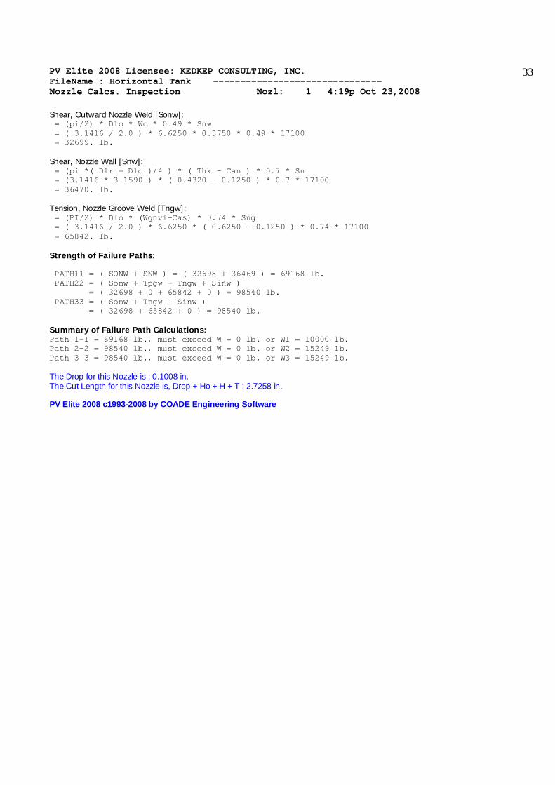
Shear, Outward Nozzle Weld [Sonw]: = (pi/2) * Dlo * Wo * 0.49 * Snw = ( 3.1416 / 2.0 ) * 6.6250 * 0.3750 * 0.49 * 17100 = 32699. lb. Shear, Nozzle Wall [Snw]: = (pi *( Dlr + Dlo )/4 ) * ( Thk - Can ) * 0.7 * Sn = (3.1416 * 3.1590 ) * ( 0.4320 - 0.1250 ) * 0.7 * 17100 = 36470. lb. Tension, Nozzle Groove Weld [Tngw]: = (PI/2) * Dlo * (Wgnvi-Cas) * 0.74 * Sng = ( 3.1416 / 2.0 ) * 6.6250 * ( 0.6250 - 0.1250 ) * 0.74 * 17100 = 65842. lb. Strength of Failure Paths: PATH11 = ( SONW + SNW ) = ( 32698 + 36469 ) = 69168 lb. PATH22 = ( Sonw + Tpgw + Tngw + Sinw ) = ( 32698 + 0 + 65842 + 0 ) = 98540 lb. PATH33 = ( Sonw + Tngw + Sinw ) = ( 32698 + 65842 + 0 ) = 98540 lb. Summary of Failure Path Calculations: Path 1-1 = 69168 lb., must exceed W = 0 lb. or W1 = 10000 lb. Path 2-2 = 98540 lb., must exceed W = 0 lb. or W2 = 15249 lb. Path 3-3 = 98540 lb., must exceed W = 0 lb. or W3 = 15249 lb. The Drop for this Nozzle is : 0.1008 in. The Cut Length for this Nozzle is, Drop + Ho + H + T : 2.7258 in. PV Elite 2008 c1993-2008 by COADE Engineering Software

PV Elite 2008 Licensee: KEDKEP CONSULTING, INC. FileName : Horizontal Tank ------------------------------- Nozzle Calcs. Outlet Nozl: 2 4:19p Oct 23,2008
34
INPUT VALUES, Nozzle Description: Outlet From : 10 Pressure for Nozzle Reinforcement Calculations P 100.000 psig Temperature for Internal Pressure Temp 200 F Design External Pressure Pext 15.00 psig Temperature for External Pressure Tempex 200 F Shell Material SA-516 70 Shell Allowable Stress at Temperature S 20000.00 psi Shell Allowable Stress At Ambient Sa 20000.00 psi Inside Diameter of Elliptical Head D 60.0000 in. Aspect Ratio of Elliptical Head Ar 2.00 Head Actual Thickness T 0.6250 in. Head Internal Corrosion Allowance Cas 0.1250 in. Head External Corrosion Allowance Caext 0.0000 in. Distance from Head Centerline L1 15.0000 in. User Entered Minimum Design Metal Temperature -20.00 F Nozzle Material SA-106 B Nozzle Allowable Stress at Temperature Sn 17100.00 psi Nozzle Allowable Stress At Ambient Sna 17100.00 psi Nozzle Diameter Basis (for tr calc only) Inbase ID Layout Angle 0.00 deg Nozzle Diameter Dia 6.0000 in. Nozzle Size and Thickness Basis Idbn Nominal Nominal Thickness of Nozzle Thknom 80 Nozzle Flange Material SA-105 Nozzle Flange Type Weld Neck Flange Nozzle Corrosion Allowance Can 0.1250 in. Joint Efficiency of Shell Seam at Nozzle Es 1.00 Joint Efficiency of Nozzle Neck En 1.00 Nozzle Outside Projection Ho 2.0000 in. Weld leg size between Nozzle and Pad/Shell Wo 0.3750 in. Groove weld depth between Nozzle and Vessel Wgnv 0.6250 in. Nozzle Inside Projection H 0.0000 in. Weld leg size, Inside Nozzle to Shell Wi 0.0000 in. ASME Code Weld Type per UW-16 None Class of attached Flange 150 Grade of attached Flange GR 1.1 The Pressure Design option was Design Pressure + static head Nozzle Sketch | | | | | | | | ____________/| | | \ | | | \ | | |____________\|__| Insert Nozzle No Pad, no Inside projection
PV Elite 2008 Licensee: KEDKEP CONSULTING, INC. FileName : Horizontal Tank ------------------------------- Nozzle Calcs. Outlet Nozl: 2 4:19p Oct 23,2008
35
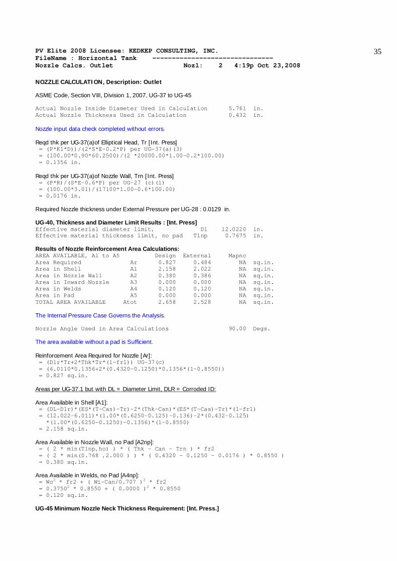
NOZZLE CALCULATION, Description: Outlet ASME Code, Section VIII, Division 1, 2007, UG-37 to UG-45 Actual Nozzle Inside Diameter Used in Calculation 5.761 in. Actual Nozzle Thickness Used in Calculation 0.432 in. Nozzle input data check completed without errors. Reqd thk per UG-37(a)of Elliptical Head, Tr [Int. Press] = (P*K1*D))/(2*S*E-0.2*P) per UG-37(a)(3) = (100.00*0.90*60.2500)/(2 *20000.00*1.00-0.2*100.00) = 0.1356 in. Reqd thk per UG-37(a)of Nozzle Wall, Trn [Int. Press] = (P*R)/(S*E-0.6*P) per UG-27 (c)(1) = (100.00*3.01)/(17100*1.00-0.6*100.00) = 0.0176 in. Required Nozzle thickness under External Pressure per UG-28 : 0.0129 in. UG-40, Thickness and Diameter Limit Results : [Int. Press] Effective material diameter limit, Dl 12.0220 in. Effective material thickness limit, no pad Tlnp 0.7675 in. Results of Nozzle Reinforcement Area Calculations: AREA AVAILABLE, A1 to A5 Design External Mapnc Area Required Ar 0.827 0.484 NA sq.in. Area in Shell A1 2.158 2.022 NA sq.in. Area in Nozzle Wall A2 0.380 0.386 NA sq.in. Area in Inward Nozzle A3 0.000 0.000 NA sq.in. Area in Welds A4 0.120 0.120 NA sq.in. Area in Pad A5 0.000 0.000 NA sq.in. TOTAL AREA AVAILABLE Atot 2.658 2.528 NA sq.in. The Internal Pressure Case Governs the Analysis. Nozzle Angle Used in Area Calculations 90.00 Degs. The area available without a pad is Sufficient. Reinforcement Area Required for Nozzle [Ar]: = (Dlr*Tr+2*Thk*Tr*(1-fr1)) UG-37(c) = (6.0110*0.1356+2*(0.4320-0.1250)*0.1356*(1-0.8550)) = 0.827 sq.in. Areas per UG-37.1 but with DL = Diameter Limit, DLR = Corroded ID: Area Available in Shell [A1]: = (DL-Dlr)*(ES*(T-Cas)-Tr)-2*(Thk-Can)*(ES*(T-Cas)-Tr)*(1-fr1) = (12.022-6.011)*(1.00*(0.6250-0.125)-0.136)-2*(0.432-0.125) *(1.00*(0.6250-0.1250)-0.1356)*(1-0.8550) = 2.158 sq.in. Area Available in Nozzle Wall, no Pad [A2np]: = ( 2 * min(Tlnp,ho) ) * ( Thk - Can - Trn ) * fr2 = ( 2 * min(0.768 ,2.000 ) ) * ( 0.4320 - 0.1250 - 0.0176 ) * 0.8550 ) = 0.380 sq.in. Area Available in Welds, no Pad [A4np]: = Wo2 * fr2 + ( Wi-Can/0.707 )2 * fr2 = 0.37502 * 0.8550 + ( 0.0000 )2 * 0.8550 = 0.120 sq.in. UG-45 Minimum Nozzle Neck Thickness Requirement: [Int. Press.]
PV Elite 2008 Licensee: KEDKEP CONSULTING, INC. FileName : Horizontal Tank ------------------------------- Nozzle Calcs. Outlet Nozl: 2 4:19p Oct 23,2008
36
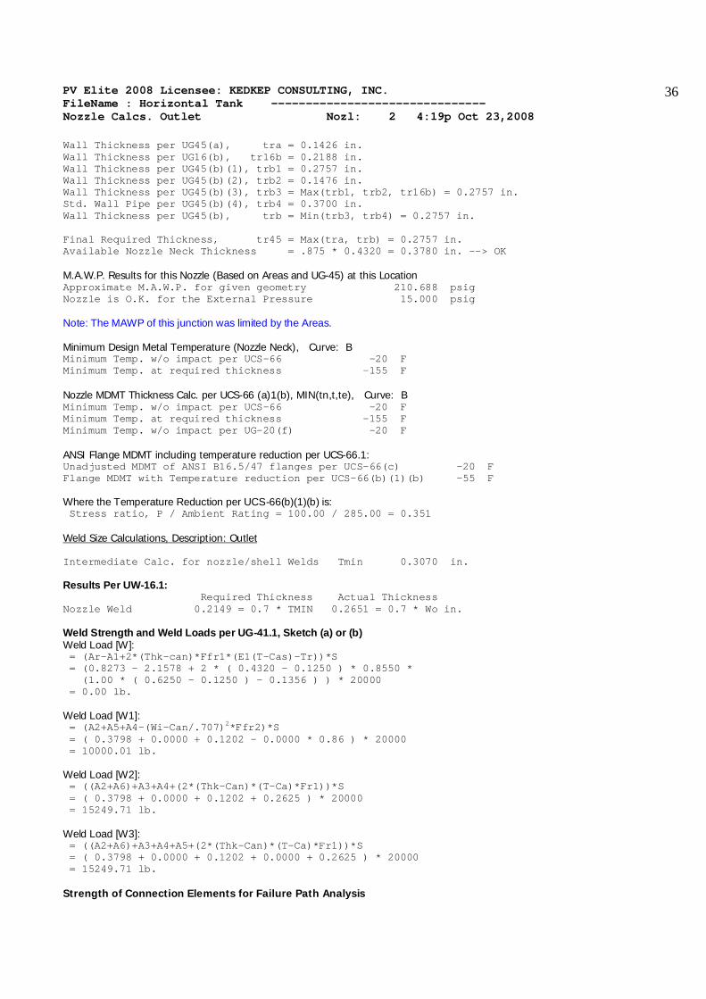
Wall Thickness per UG45(a), tra = 0.1426 in. Wall Thickness per UG16(b), tr16b = 0.2188 in. Wall Thickness per UG45(b)(1), trb1 = 0.2757 in. Wall Thickness per UG45(b)(2), trb2 = 0.1476 in. Wall Thickness per UG45(b)(3), trb3 = Max(trb1, trb2, tr16b) = 0.2757 in. Std. Wall Pipe per UG45(b)(4), trb4 = 0.3700 in. Wall Thickness per UG45(b), trb = Min(trb3, trb4) = 0.2757 in. Final Required Thickness, tr45 = Max(tra, trb) = 0.2757 in. Available Nozzle Neck Thickness = .875 * 0.4320 = 0.3780 in. --> OK M.A.W.P. Results for this Nozzle (Based on Areas and UG-45) at this Location Approximate M.A.W.P. for given geometry 210.688 psig Nozzle is O.K. for the External Pressure 15.000 psig Note: The MAWP of this junction was limited by the Areas. Minimum Design Metal Temperature (Nozzle Neck), Curve: B Minimum Temp. w/o impact per UCS-66 -20 F Minimum Temp. at required thickness -155 F Nozzle MDMT Thickness Calc. per UCS-66 (a)1(b), MIN(tn,t,te), Curve: B Minimum Temp. w/o impact per UCS-66 -20 F Minimum Temp. at required thickness -155 F Minimum Temp. w/o impact per UG-20(f) -20 F ANSI Flange MDMT including temperature reduction per UCS-66.1: Unadjusted MDMT of ANSI B16.5/47 flanges per UCS-66(c) -20 F Flange MDMT with Temperature reduction per UCS-66(b)(1)(b) -55 F Where the Temperature Reduction per UCS-66(b)(1)(b) is: Stress ratio, P / Ambient Rating = 100.00 / 285.00 = 0.351 Weld Size Calculations, Description: Outlet Intermediate Calc. for nozzle/shell Welds Tmin 0.3070 in. Results Per UW-16.1: Required Thickness Actual Thickness Nozzle Weld 0.2149 = 0.7 * TMIN 0.2651 = 0.7 * Wo in. Weld Strength and Weld Loads per UG-41.1, Sketch (a) or (b) Weld Load [W]: = (Ar-A1+2*(Thk-can)*Ffr1*(E1(T-Cas)-Tr))*S = (0.8273 - 2.1578 + 2 * ( 0.4320 - 0.1250 ) * 0.8550 * (1.00 * ( 0.6250 - 0.1250 ) - 0.1356 ) ) * 20000 = 0.00 lb. Weld Load [W1]: = (A2+A5+A4-(Wi-Can/.707)2*Ffr2)*S = ( 0.3798 + 0.0000 + 0.1202 - 0.0000 * 0.86 ) * 20000 = 10000.01 lb. Weld Load [W2]: = ((A2+A6)+A3+A4+(2*(Thk-Can)*(T-Ca)*Fr1))*S = ( 0.3798 + 0.0000 + 0.1202 + 0.2625 ) * 20000 = 15249.71 lb. Weld Load [W3]: = ((A2+A6)+A3+A4+A5+(2*(Thk-Can)*(T-Ca)*Fr1))*S = ( 0.3798 + 0.0000 + 0.1202 + 0.0000 + 0.2625 ) * 20000 = 15249.71 lb. Strength of Connection Elements for Failure Path Analysis
PV Elite 2008 Licensee: KEDKEP CONSULTING, INC. FileName : Horizontal Tank ------------------------------- Nozzle Calcs. Outlet Nozl: 2 4:19p Oct 23,2008
37
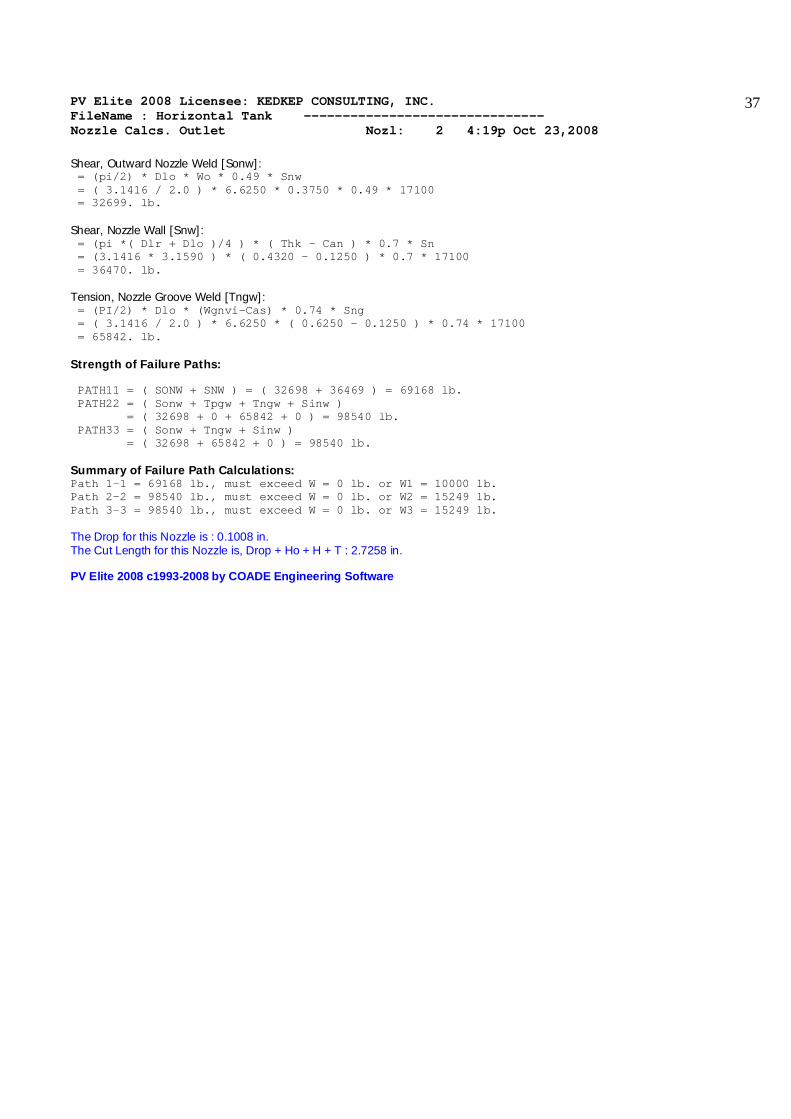
Shear, Outward Nozzle Weld [Sonw]: = (pi/2) * Dlo * Wo * 0.49 * Snw = ( 3.1416 / 2.0 ) * 6.6250 * 0.3750 * 0.49 * 17100 = 32699. lb. Shear, Nozzle Wall [Snw]: = (pi *( Dlr + Dlo )/4 ) * ( Thk - Can ) * 0.7 * Sn = (3.1416 * 3.1590 ) * ( 0.4320 - 0.1250 ) * 0.7 * 17100 = 36470. lb. Tension, Nozzle Groove Weld [Tngw]: = (PI/2) * Dlo * (Wgnvi-Cas) * 0.74 * Sng = ( 3.1416 / 2.0 ) * 6.6250 * ( 0.6250 - 0.1250 ) * 0.74 * 17100 = 65842. lb. Strength of Failure Paths: PATH11 = ( SONW + SNW ) = ( 32698 + 36469 ) = 69168 lb. PATH22 = ( Sonw + Tpgw + Tngw + Sinw ) = ( 32698 + 0 + 65842 + 0 ) = 98540 lb. PATH33 = ( Sonw + Tngw + Sinw ) = ( 32698 + 65842 + 0 ) = 98540 lb. Summary of Failure Path Calculations: Path 1-1 = 69168 lb., must exceed W = 0 lb. or W1 = 10000 lb. Path 2-2 = 98540 lb., must exceed W = 0 lb. or W2 = 15249 lb. Path 3-3 = 98540 lb., must exceed W = 0 lb. or W3 = 15249 lb. The Drop for this Nozzle is : 0.1008 in. The Cut Length for this Nozzle is, Drop + Ho + H + T : 2.7258 in. PV Elite 2008 c1993-2008 by COADE Engineering Software

PV Elite 2008 Licensee: KEDKEP CONSULTING, INC. FileName : Horizontal Tank ------------------------------- Nozzle Calcs. Manhole Nozl: 3 4:19p Oct 23,2008
38
INPUT VALUES, Nozzle Description: Manhole From : 20 Pressure for Nozzle Reinforcement Calculations P 150.000 psig Temperature for Internal Pressure Temp 200 F Design External Pressure Pext 15.00 psig Temperature for External Pressure Tempex 200 F Shell Material SA-516 70 Shell Allowable Stress at Temperature S 20000.00 psi Shell Allowable Stress At Ambient Sa 20000.00 psi Inside Diameter of Cylindrical Shell D 60.0000 in. Design Length of Section L 134.0000 in. Shell Actual Thickness T 0.6250 in. Shell Internal Corrosion Allowance Cas 0.1250 in. Shell External Corrosion Allowance Caext 0.0000 in. Distance from Bottom/Left Tangent 5.1667 ft. User Entered Minimum Design Metal Temperature -20.00 F Nozzle Material SA-516 70 Nozzle Allowable Stress at Temperature Sn 20000.00 psi Nozzle Allowable Stress At Ambient Sna 20000.00 psi Nozzle Diameter Basis (for tr calc only) Inbase ID Layout Angle 0.00 deg Nozzle Diameter Dia 16.0000 in. Nozzle Size and Thickness Basis Idbn Actual Actual Thickness of Nozzle Thk 0.7500 in. Nozzle Flange Material SA-105 Nozzle Flange Type Weld Neck Flange Nozzle Corrosion Allowance Can 0.1250 in. Joint Efficiency of Shell Seam at Nozzle Es 1.00 Joint Efficiency of Nozzle Neck En 1.00 Nozzle Outside Projection Ho 4.0000 in. Weld leg size between Nozzle and Pad/Shell Wo 0.3750 in. Groove weld depth between Nozzle and Vessel Wgnv 0.6250 in. Nozzle Inside Projection H 0.0000 in. Weld leg size, Inside Nozzle to Shell Wi 0.0000 in. ASME Code Weld Type per UW-16 None Class of attached Flange 150 Grade of attached Flange GR 1.1 The Pressure Design option was Design Pressure + static head Nozzle Sketch | | | | | | | | ____________/| | | \ | | | \ | | |____________\|__| Insert Nozzle No Pad, no Inside projection

PV Elite 2008 Licensee: KEDKEP CONSULTING, INC. FileName : Horizontal Tank ------------------------------- Nozzle Calcs. Manhole Nozl: 3 4:19p Oct 23,2008
39
NOZZLE CALCULATION, Description: Manhole ASME Code, Section VIII, Division 1, 2007, UG-37 to UG-45 Actual Nozzle Inside Diameter Used in Calculation 16.000 in. Actual Nozzle Thickness Used in Calculation 0.750 in. Nozzle input data check completed without errors. Reqd thk per UG-37(a)of Cylindrical Shell, Tr [Int. Press] = (P*R)/(S*E-0.6*P) per UG-27 (c)(1) = (150.00*30.1250)/(20000*1.00-0.6*150.00) = 0.2270 in. Reqd thk per UG-37(a)of Nozzle Wall, Trn [Int. Press] = (P*R)/(S*E-0.6*P) per UG-27 (c)(1) = (150.00*8.12)/(20000*1.00-0.6*150.00) = 0.0612 in. Required Nozzle thickness under External Pressure per UG-28 : 0.0303 in. UG-40, Thickness and Diameter Limit Results : [Int. Press] Effective material diameter limit, Dl 32.5000 in. Effective material thickness limit, no pad Tlnp 1.2500 in. Results of Nozzle Reinforcement Area Calculations: AREA AVAILABLE, A1 to A5 Design External Mapnc Area Required Ar 3.688 2.192 NA sq.in. Area in Shell A1 4.437 3.741 NA sq.in. Area in Nozzle Wall A2 1.409 1.487 NA sq.in. Area in Inward Nozzle A3 0.000 0.000 NA sq.in. Area in Welds A4 0.141 0.141 NA sq.in. Area in Pad A5 0.000 0.000 NA sq.in. TOTAL AREA AVAILABLE Atot 5.987 5.368 NA sq.in. The Internal Pressure Case Governs the Analysis. Nozzle Angle Used in Area Calculations 90.00 Degs. The area available without a pad is Sufficient. Reinforcement Area Required for Nozzle [Ar]: = (Dlr*Tr+2*Thk*Tr*(1-fr1)) UG-37(c) = (16.2500*0.2270+2*(0.7500-0.1250)*0.2270*(1-1.0000)) = 3.688 sq.in. Areas per UG-37.1 but with DL = Diameter Limit, DLR = Corroded ID: Area Available in Shell [A1]: = (DL-Dlr)*(ES*(T-Cas)-Tr)-2*(Thk-Can)*(ES*(T-Cas)-Tr)*(1-fr1) = (32.500-16.250)*(1.00*(0.6250-0.125)-0.227)-2*(0.750-0.125) *(1.00*(0.6250-0.1250)-0.2270)*(1-1.0000) = 4.437 sq.in. Area Available in Nozzle Wall, no Pad [A2np]: = ( 2 * min(Tlnp,ho) ) * ( Thk - Can - Trn ) * fr2 = ( 2 * min(1.250 ,4.000 ) ) * ( 0.7500 - 0.1250 - 0.0612 ) * 1.0000 ) = 1.409 sq.in. Area Available in Welds, no Pad [A4np]: = Wo2 * fr2 + ( Wi-Can/0.707 )2 * fr2 = 0.37502 * 1.0000 + ( 0.0000 )2 * 1.0000 = 0.141 sq.in. UG-45 Minimum Nozzle Neck Thickness Requirement: [Int. Press.]

PV Elite 2008 Licensee: KEDKEP CONSULTING, INC. FileName : Horizontal Tank ------------------------------- Nozzle Calcs. Manhole Nozl: 3 4:19p Oct 23,2008
40
Wall Thickness per UG45(a), tra = 0.1862 in. Wall Thickness per UG16(b), tr16b = 0.2188 in. Wall Thickness per UG45(b)(1), trb1 = 0.3520 in. Wall Thickness per UG45(b)(2), trb2 = 0.1476 in. Wall Thickness per UG45(b)(3), trb3 = Max(trb1, trb2, tr16b) = 0.3520 in. Std. Wall Pipe per UG45(b)(4), trb4 = 0.4531 in. Wall Thickness per UG45(b), trb = Min(trb3, trb4) = 0.3520 in. Final Required Thickness, tr45 = Max(tra, trb) = 0.3520 in. Available Nozzle Neck Thickness = 0.7500 in. --> OK M.A.W.P. Results for this Nozzle (Based on Areas and UG-45) at this Location Approximate M.A.W.P. for given geometry 195.800 psig Nozzle is O.K. for the External Pressure 15.000 psig Note: The MAWP of this junction was limited by the Areas. Minimum Design Metal Temperature (Nozzle Neck), Curve: B Minimum Temp. w/o impact per UCS-66 16 F Minimum Temp. at required thickness -124 F Minimum Temp. w/o impact per UG-20(f) -20 F Nozzle MDMT Thickness Calc. per UCS-66 (a)1(b), MIN(tn,t,te), Curve: B Minimum Temp. w/o impact per UCS-66 6 F Minimum Temp. at required thickness -134 F Minimum Temp. w/o impact per UG-20(f) -20 F ANSI Flange MDMT including temperature reduction per UCS-66.1: Unadjusted MDMT of ANSI B16.5/47 flanges per UCS-66(c) -20 F Flange MDMT with Temperature reduction per UCS-66(b)(1)(b) -55 F Where the Temperature Reduction per UCS-66(b)(1)(b) is: Stress ratio, P / Ambient Rating = 150.00 / 285.00 = 0.526 Weld Size Calculations, Description: Manhole Intermediate Calc. for nozzle/shell Welds Tmin 0.5000 in. Results Per UW-16.1: Required Thickness Actual Thickness Nozzle Weld 0.2500 = Min per Code 0.2651 = 0.7 * Wo in. Weld Strength and Weld Loads per UG-41.1, Sketch (a) or (b) Weld Load [W]: = (Ar-A1+2*(Thk-can)*Ffr1*(E1(T-Cas)-Tr))*S = (3.6881 - 4.4369 + 2 * ( 0.7500 - 0.1250 ) * 1.0000 * (1.00 * ( 0.6250 - 0.1250 ) - 0.2270 ) ) * 20000 = 0.00 lb. Weld Load [W1]: = (A2+A5+A4-(Wi-Can/.707)2*Ffr2)*S = ( 1.4095 + 0.0000 + 0.1406 - 0.0000 * 1.00 ) * 20000 = 31001.85 lb. Weld Load [W2]: = ((A2+A6)+A3+A4+(2*(Thk-Can)*(T-Ca)*Fr1))*S = ( 1.4095 + 0.0000 + 0.1406 + 0.6250 ) * 20000 = 43501.85 lb. Weld Load [W3]: = ((A2+A6)+A3+A4+A5+(2*(Thk-Can)*(T-Ca)*Fr1))*S = ( 1.4095 + 0.0000 + 0.1406 + 0.0000 + 0.6250 ) * 20000 = 43501.85 lb. Strength of Connection Elements for Failure Path Analysis

PV Elite 2008 Licensee: KEDKEP CONSULTING, INC. FileName : Horizontal Tank ------------------------------- Nozzle Calcs. Manhole Nozl: 3 4:19p Oct 23,2008
41
Shear, Outward Nozzle Weld [Sonw]: = (pi/2) * Dlo * Wo * 0.49 * Snw = ( 3.1416 / 2.0 ) * 17.5000 * 0.3750 * 0.49 * 20000 = 101022. lb. Shear, Nozzle Wall [Snw]: = (pi *( Dlr + Dlo )/4 ) * ( Thk - Can ) * 0.7 * Sn = (3.1416 * 8.4375 ) * ( 0.7500 - 0.1250 ) * 0.7 * 20000 = 231938. lb. Tension, Nozzle Groove Weld [Tngw]: = (PI/2) * Dlo * (Wgnvi-Cas) * 0.74 * Sng = ( 3.1416 / 2.0 ) * 17.5000 * ( 0.6250 - 0.1250 ) * 0.74 * 20000 = 203418. lb. Strength of Failure Paths: PATH11 = ( SONW + SNW ) = ( 101021 + 231937 ) = 332959 lb. PATH22 = ( Sonw + Tpgw + Tngw + Sinw ) = ( 101021 + 0 + 203418 + 0 ) = 304439 lb. PATH33 = ( Sonw + Tngw + Sinw ) = ( 101021 + 203418 + 0 ) = 304439 lb. Summary of Failure Path Calculations: Path 1-1 = 332959 lb., must exceed W = 0 lb. or W1 = 31001 lb. Path 2-2 = 304439 lb., must exceed W = 0 lb. or W2 = 43501 lb. Path 3-3 = 304439 lb., must exceed W = 0 lb. or W3 = 43501 lb. The Drop for this Nozzle is : 1.3044 in. The Cut Length for this Nozzle is, Drop + Ho + H + T : 5.9294 in. PV Elite 2008 c1993-2008 by COADE Engineering Software
PV Elite 2008 Licensee: KEDKEP CONSULTING, INC. FileName : Horizontal Tank ------------------------------- Nozzle Calcs. Drain Nozl: 4 4:19p Oct 23,2008
42
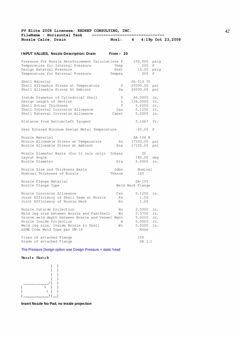
INPUT VALUES, Nozzle Description: Drain From : 20 Pressure for Nozzle Reinforcement Calculations P 150.000 psig Temperature for Internal Pressure Temp 200 F Design External Pressure Pext 15.00 psig Temperature for External Pressure Tempex 200 F Shell Material SA-516 70 Shell Allowable Stress at Temperature S 20000.00 psi Shell Allowable Stress At Ambient Sa 20000.00 psi Inside Diameter of Cylindrical Shell D 60.0000 in. Design Length of Section L 134.0000 in. Shell Actual Thickness T 0.6250 in. Shell Internal Corrosion Allowance Cas 0.1250 in. Shell External Corrosion Allowance Caext 0.0000 in. Distance from Bottom/Left Tangent 5.1667 ft. User Entered Minimum Design Metal Temperature -20.00 F Nozzle Material SA-106 B Nozzle Allowable Stress at Temperature Sn 17100.00 psi Nozzle Allowable Stress At Ambient Sna 17100.00 psi Nozzle Diameter Basis (for tr calc only) Inbase ID Layout Angle 180.00 deg Nozzle Diameter Dia 2.0000 in. Nozzle Size and Thickness Basis Idbn Nominal Nominal Thickness of Nozzle Thknom 160 Nozzle Flange Material SA-105 Nozzle Flange Type Weld Neck Flange Nozzle Corrosion Allowance Can 0.1250 in. Joint Efficiency of Shell Seam at Nozzle Es 1.00 Joint Efficiency of Nozzle Neck En 1.00 Nozzle Outside Projection Ho 2.0000 in. Weld leg size between Nozzle and Pad/Shell Wo 0.3750 in. Groove weld depth between Nozzle and Vessel Wgnv 0.6250 in. Nozzle Inside Projection H 0.0000 in. Weld leg size, Inside Nozzle to Shell Wi 0.0000 in. ASME Code Weld Type per UW-16 None Class of attached Flange 150 Grade of attached Flange GR 1.1 The Pressure Design option was Design Pressure + static head Nozzle Sketch | | | | | | | | ____________/| | | \ | | | \ | | |____________\|__| Insert Nozzle No Pad, no Inside projection

PV Elite 2008 Licensee: KEDKEP CONSULTING, INC. FileName : Horizontal Tank ------------------------------- Nozzle Calcs. Drain Nozl: 4 4:19p Oct 23,2008
43
NOZZLE CALCULATION, Description: Drain ASME Code, Section VIII, Division 1, 2007, UG-37 to UG-45 Actual Nozzle Inside Diameter Used in Calculation 1.687 in. Actual Nozzle Thickness Used in Calculation 0.344 in. Nozzle input data check completed without errors. Reqd thk per UG-37(a)of Cylindrical Shell, Tr [Int. Press] = (P*R)/(S*E-0.6*P) per UG-27 (c)(1) = (150.00*30.1250)/(20000*1.00-0.6*150.00) = 0.2270 in. Reqd thk per UG-37(a)of Nozzle Wall, Trn [Int. Press] = (P*R)/(S*E-0.6*P) per UG-27 (c)(1) = (150.00*0.97)/(17100*1.00-0.6*150.00) = 0.0085 in. Required Nozzle thickness under External Pressure per UG-28 : 0.0071 in. UG-40, Thickness and Diameter Limit Results : [Int. Press] Effective material diameter limit, Dl 3.8740 in. Effective material thickness limit, no pad Tlnp 0.5475 in. Note: Taking a UG-36(c)(3)(a) exemption for Drain . This calculation is valid for nozzles that meet all the requirements of paragraph UG-36. Please check the Code carefully, especially for nozzles that are not isolated or do not meet Code spacing requirements. It may be necessary to force the program to print the areas per UG-37. UG-45 Minimum Nozzle Neck Thickness Requirement: [Int. Press.] Wall Thickness per UG45(a), tra = 0.1335 in. Wall Thickness per UG16(b), tr16b = 0.2188 in. Wall Thickness per UG45(b)(1), trb1 = 0.3520 in. Wall Thickness per UG45(b)(2), trb2 = 0.1476 in. Wall Thickness per UG45(b)(3), trb3 = Max(trb1, trb2, tr16b) = 0.3520 in. Std. Wall Pipe per UG45(b)(4), trb4 = 0.2598 in. Wall Thickness per UG45(b), trb = Min(trb3, trb4) = 0.2598 in. Final Required Thickness, tr45 = Max(tra, trb) = 0.2598 in. Available Nozzle Neck Thickness = .875 * 0.3440 = 0.3010 in. --> OK Minimum Design Metal Temperature (Nozzle Neck), Curve: B Minimum Temp. w/o impact per UCS-66 -20 F Minimum Temp. at required thickness -155 F Nozzle MDMT Thickness Calc. per UCS-66 (a)1(b), MIN(tn,t,te), Curve: B Minimum Temp. w/o impact per UCS-66 -20 F Minimum Temp. at required thickness -155 F Minimum Temp. w/o impact per UG-20(f) -20 F ANSI Flange MDMT including temperature reduction per UCS-66.1: Unadjusted MDMT of ANSI B16.5/47 flanges per UCS-66(c) -20 F Flange MDMT with Temperature reduction per UCS-66(b)(1)(b) -55 F Where the Temperature Reduction per UCS-66(b)(1)(b) is: Stress ratio, P / Ambient Rating = 150.00 / 285.00 = 0.526 Weld Size Calculations, Description: Drain Intermediate Calc. for nozzle/shell Welds Tmin 0.2190 in. Results Per UW-16.1:
PV Elite 2008 Licensee: KEDKEP CONSULTING, INC. FileName : Horizontal Tank ------------------------------- Nozzle Calcs. Drain Nozl: 4 4:19p Oct 23,2008
44
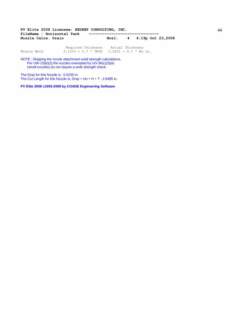
Required Thickness Actual Thickness Nozzle Weld 0.1533 = 0.7 * TMIN 0.2651 = 0.7 * Wo in. NOTE : Skipping the nozzle attachment weld strength calculations. Per UW-15(b)(2) the nozzles exempted by UG-36(c)(3)(a) (small nozzles) do not require a weld strength check. The Drop for this Nozzle is : 0.0235 in. The Cut Length for this Nozzle is, Drop + Ho + H + T : 2.6485 in. PV Elite 2008 c1993-2008 by COADE Engineering Software

PV Elite 2008 Licensee: KEDKEP CONSULTING, INC. FileName : Horizontal Tank ------------------------------- Nozzle Calcs. Inlet Nozl: 5 4:19p Oct 23,2008
45
INPUT VALUES, Nozzle Description: Inlet From : 30 Pressure for Nozzle Reinforcement Calculations P 150.000 psig Temperature for Internal Pressure Temp 200 F Design External Pressure Pext 15.00 psig Temperature for External Pressure Tempex 200 F Shell Material SA-516 70 Shell Allowable Stress at Temperature S 20000.00 psi Shell Allowable Stress At Ambient Sa 20000.00 psi Inside Diameter of Elliptical Head D 60.0000 in. Aspect Ratio of Elliptical Head Ar 2.00 Head Actual Thickness T 0.6250 in. Head Internal Corrosion Allowance Cas 0.1250 in. Head External Corrosion Allowance Caext 0.0000 in. Distance from Head Centerline L1 0.0000 in. User Entered Minimum Design Metal Temperature -20.00 F Nozzle Material SA-106 B Nozzle Allowable Stress at Temperature Sn 17100.00 psi Nozzle Allowable Stress At Ambient Sna 17100.00 psi Nozzle Diameter Basis (for tr calc only) Inbase ID Layout Angle 0.00 deg Nozzle Diameter Dia 4.0000 in. Nozzle Size and Thickness Basis Idbn Nominal Nominal Thickness of Nozzle Thknom 120 Nozzle Flange Material SA-105 Nozzle Flange Type Weld Neck Flange Nozzle Corrosion Allowance Can 0.1250 in. Joint Efficiency of Shell Seam at Nozzle Es 1.00 Joint Efficiency of Nozzle Neck En 1.00 Nozzle Outside Projection Ho 2.0000 in. Weld leg size between Nozzle and Pad/Shell Wo 0.3750 in. Groove weld depth between Nozzle and Vessel Wgnv 0.6250 in. Nozzle Inside Projection H 0.0000 in. Weld leg size, Inside Nozzle to Shell Wi 0.0000 in. ASME Code Weld Type per UW-16 None Class of attached Flange 150 Grade of attached Flange GR 1.1 The Pressure Design option was Design Pressure + static head Nozzle Sketch | | | | | | | | ____________/| | | \ | | | \ | | |____________\|__| Insert Nozzle No Pad, no Inside projection

PV Elite 2008 Licensee: KEDKEP CONSULTING, INC. FileName : Horizontal Tank ------------------------------- Nozzle Calcs. Inlet Nozl: 5 4:19p Oct 23,2008
46
NOZZLE CALCULATION, Description: Inlet ASME Code, Section VIII, Division 1, 2007, UG-37 to UG-45 Actual Nozzle Inside Diameter Used in Calculation 3.624 in. Actual Nozzle Thickness Used in Calculation 0.438 in. Nozzle input data check completed without errors. Reqd thk per UG-37(a)of Elliptical Head, Tr [Int. Press] = (P*K1*D))/(2*S*E-0.2*P) per UG-37(a)(3) = (150.00*0.90*60.2500)/(2 *20000.00*1.00-0.2*150.00) = 0.2035 in. Reqd thk per UG-37(a)of Nozzle Wall, Trn [Int. Press] = (P*R)/(S*E-0.6*P) per UG-27 (c)(1) = (150.00*1.94)/(17100*1.00-0.6*150.00) = 0.0171 in. Required Nozzle thickness under External Pressure per UG-28 : 0.0103 in. UG-40, Thickness and Diameter Limit Results : [Int. Press] Effective material diameter limit, Dl 7.7480 in. Effective material thickness limit, no pad Tlnp 0.7825 in. Results of Nozzle Reinforcement Area Calculations: AREA AVAILABLE, A1 to A5 Design External Mapnc Area Required Ar 0.807 0.314 NA sq.in. Area in Shell A1 1.122 1.292 NA sq.in. Area in Nozzle Wall A2 0.396 0.405 NA sq.in. Area in Inward Nozzle A3 0.000 0.000 NA sq.in. Area in Welds A4 0.120 0.120 NA sq.in. Area in Pad A5 0.000 0.000 NA sq.in. TOTAL AREA AVAILABLE Atot 1.638 1.817 NA sq.in. The Internal Pressure Case Governs the Analysis. Nozzle Angle Used in Area Calculations 90.00 Degs. The area available without a pad is Sufficient. Reinforcement Area Required for Nozzle [Ar]: = (Dlr*Tr+2*Thk*Tr*(1-fr1)) UG-37(c) = (3.8740*0.2035+2*(0.4380-0.1250)*0.2035*(1-0.8550)) = 0.807 sq.in. Areas per UG-37.1 but with DL = Diameter Limit, DLR = Corroded ID: Area Available in Shell [A1]: = (DL-Dlr)*(ES*(T-Cas)-Tr)-2*(Thk-Can)*(ES*(T-Cas)-Tr)*(1-fr1) = (7.748-3.874)*(1.00*(0.6250-0.125)-0.203)-2*(0.438-0.125) *(1.00*(0.6250-0.1250)-0.2035)*(1-0.8550) = 1.122 sq.in. Area Available in Nozzle Wall, no Pad [A2np]: = ( 2 * min(Tlnp,ho) ) * ( Thk - Can - Trn ) * fr2 = ( 2 * min(0.782 ,2.000 ) ) * ( 0.4380 - 0.1250 - 0.0171 ) * 0.8550 ) = 0.396 sq.in. Area Available in Welds, no Pad [A4np]: = Wo2 * fr2 + ( Wi-Can/0.707 )2 * fr2 = 0.37502 * 0.8550 + ( 0.0000 )2 * 0.8550 = 0.120 sq.in. UG-45 Minimum Nozzle Neck Thickness Requirement: [Int. Press.]

PV Elite 2008 Licensee: KEDKEP CONSULTING, INC. FileName : Horizontal Tank ------------------------------- Nozzle Calcs. Inlet Nozl: 5 4:19p Oct 23,2008
47
Wall Thickness per UG45(a), tra = 0.1421 in. Wall Thickness per UG16(b), tr16b = 0.2188 in. Wall Thickness per UG45(b)(1), trb1 = 0.3511 in. Wall Thickness per UG45(b)(2), trb2 = 0.1476 in. Wall Thickness per UG45(b)(3), trb3 = Max(trb1, trb2, tr16b) = 0.3511 in. Std. Wall Pipe per UG45(b)(4), trb4 = 0.3324 in. Wall Thickness per UG45(b), trb = Min(trb3, trb4) = 0.3324 in. Final Required Thickness, tr45 = Max(tra, trb) = 0.3324 in. Available Nozzle Neck Thickness = .875 * 0.4380 = 0.3832 in. --> OK M.A.W.P. Results for this Nozzle (Based on Areas and UG-45) at this Location Approximate M.A.W.P. for given geometry 227.940 psig Nozzle is O.K. for the External Pressure 15.000 psig Note: The MAWP of this junction was limited by the Areas. Minimum Design Metal Temperature (Nozzle Neck), Curve: B Minimum Temp. w/o impact per UCS-66 -20 F Minimum Temp. at required thickness -155 F Nozzle MDMT Thickness Calc. per UCS-66 (a)1(b), MIN(tn,t,te), Curve: B Minimum Temp. w/o impact per UCS-66 -20 F Minimum Temp. at required thickness -155 F Minimum Temp. w/o impact per UG-20(f) -20 F ANSI Flange MDMT including temperature reduction per UCS-66.1: Unadjusted MDMT of ANSI B16.5/47 flanges per UCS-66(c) -20 F Flange MDMT with Temperature reduction per UCS-66(b)(1)(b) -55 F Where the Temperature Reduction per UCS-66(b)(1)(b) is: Stress ratio, P / Ambient Rating = 150.00 / 285.00 = 0.526 Weld Size Calculations, Description: Inlet Intermediate Calc. for nozzle/shell Welds Tmin 0.3130 in. Results Per UW-16.1: Required Thickness Actual Thickness Nozzle Weld 0.2191 = 0.7 * TMIN 0.2651 = 0.7 * Wo in. Weld Strength and Weld Loads per UG-41.1, Sketch (a) or (b) Weld Load [W]: = (Ar-A1+2*(Thk-can)*Ffr1*(E1(T-Cas)-Tr))*S = (0.8068 - 1.1217 + 2 * ( 0.4380 - 0.1250 ) * 0.8550 * (1.00 * ( 0.6250 - 0.1250 ) - 0.2035 ) ) * 20000 = 0.00 lb. Weld Load [W1]: = (A2+A5+A4-(Wi-Can/.707)2*Ffr2)*S = ( 0.3960 + 0.0000 + 0.1202 - 0.0000 * 0.86 ) * 20000 = 10323.92 lb. Weld Load [W2]: = ((A2+A6)+A3+A4+(2*(Thk-Can)*(T-Ca)*Fr1))*S = ( 0.3960 + 0.0000 + 0.1202 + 0.2676 ) * 20000 = 15676.22 lb. Weld Load [W3]: = ((A2+A6)+A3+A4+A5+(2*(Thk-Can)*(T-Ca)*Fr1))*S = ( 0.3960 + 0.0000 + 0.1202 + 0.0000 + 0.2676 ) * 20000 = 15676.22 lb. Strength of Connection Elements for Failure Path Analysis

PV Elite 2008 Licensee: KEDKEP CONSULTING, INC. FileName : Horizontal Tank ------------------------------- Nozzle Calcs. Inlet Nozl: 5 4:19p Oct 23,2008
48
Shear, Outward Nozzle Weld [Sonw]: = (pi/2) * Dlo * Wo * 0.49 * Snw = ( 3.1416 / 2.0 ) * 4.5000 * 0.3750 * 0.49 * 17100 = 22210. lb. Shear, Nozzle Wall [Snw]: = (pi *( Dlr + Dlo )/4 ) * ( Thk - Can ) * 0.7 * Sn = (3.1416 * 2.0935 ) * ( 0.4380 - 0.1250 ) * 0.7 * 17100 = 24641. lb. Tension, Nozzle Groove Weld [Tngw]: = (PI/2) * Dlo * (Wgnvi-Cas) * 0.74 * Sng = ( 3.1416 / 2.0 ) * 4.5000 * ( 0.6250 - 0.1250 ) * 0.74 * 17100 = 44723. lb. Strength of Failure Paths: PATH11 = ( SONW + SNW ) = ( 22210 + 24641 ) = 46851 lb. PATH22 = ( Sonw + Tpgw + Tngw + Sinw ) = ( 22210 + 0 + 44722 + 0 ) = 66933 lb. PATH33 = ( Sonw + Tngw + Sinw ) = ( 22210 + 44722 + 0 ) = 66933 lb. Summary of Failure Path Calculations: Path 1-1 = 46851 lb., must exceed W = 0 lb. or W1 = 10323 lb. Path 2-2 = 66933 lb., must exceed W = 0 lb. or W2 = 15676 lb. Path 3-3 = 66933 lb., must exceed W = 0 lb. or W3 = 15676 lb. The Drop for this Nozzle is : 0.0465 in. The Cut Length for this Nozzle is, Drop + Ho + H + T : 2.6715 in. PV Elite 2008 c1993-2008 by COADE Engineering Software
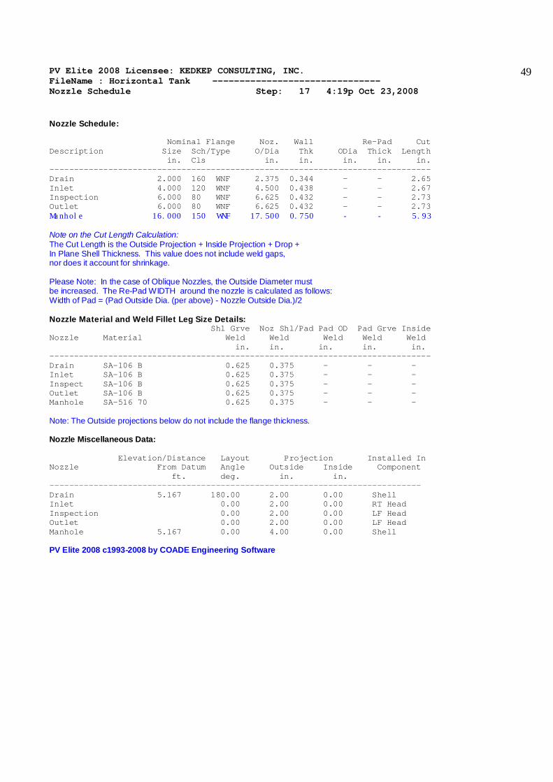
PV Elite 2008 Licensee: KEDKEP CONSULTING, INC. FileName : Horizontal Tank ------------------------------- Nozzle Schedule Step: 17 4:19p Oct 23,2008
49
Nozzle Schedule: Nominal Flange Noz. Wall Re-Pad Cut Description Size Sch/Type O/Dia Thk ODia Thick Length in. Cls in. in. in. in. in. ------------------------------------------------------------------------------ Drain 2.000 160 WNF 2.375 0.344 - - 2.65 Inlet 4.000 120 WNF 4.500 0.438 - - 2.67 Inspection 6.000 80 WNF 6.625 0.432 - - 2.73 Outlet 6.000 80 WNF 6.625 0.432 - - 2.73 Manhole 16.000 150 WNF 17.500 0.750 - - 5.93 Note on the Cut Length Calculation: The Cut Length is the Outside Projection + Inside Projection + Drop + In Plane Shell Thickness. This value does not include weld gaps, nor does it account for shrinkage. Please Note: In the case of Oblique Nozzles, the Outside Diameter must be increased. The Re-Pad WIDTH around the nozzle is calculated as follows: Width of Pad = (Pad Outside Dia. (per above) - Nozzle Outside Dia.)/2 Nozzle Material and Weld Fillet Leg Size Details: Shl Grve Noz Shl/Pad Pad OD Pad Grve Inside Nozzle Material Weld Weld Weld Weld Weld in. in. in. in. in. ------------------------------------------------------------------------------ Drain SA-106 B 0.625 0.375 - - - Inlet SA-106 B 0.625 0.375 - - - Inspect SA-106 B 0.625 0.375 - - - Outlet SA-106 B 0.625 0.375 - - - Manhole SA-516 70 0.625 0.375 - - - Note: The Outside projections below do not include the flange thickness. Nozzle Miscellaneous Data: Elevation/Distance Layout Projection Installed In Nozzle From Datum Angle Outside Inside Component ft. deg. in. in. ---------------------------------------------------------------------------- Drain 5.167 180.00 2.00 0.00 Shell Inlet 0.00 2.00 0.00 RT Head Inspection 0.00 2.00 0.00 LF Head Outlet 0.00 2.00 0.00 LF Head Manhole 5.167 0.00 4.00 0.00 Shell PV Elite 2008 c1993-2008 by COADE Engineering Software
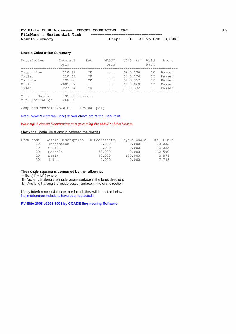
PV Elite 2008 Licensee: KEDKEP CONSULTING, INC. FileName : Horizontal Tank ------------------------------- Nozzle Summary Step: 18 4:19p Oct 23,2008
50
Nozzle Calculation Summary Description Internal Ext MAPNC UG45 [tr] Weld Areas psig psig Path --------------------------------------------------------------------------- Inspection 210.69 OK ... OK 0.276 OK Passed Outlet 210.69 OK ... OK 0.276 OK Passed Manhole 195.80 OK ... OK 0.352 OK Passed Drain 2801.97 ... ... OK 0.260 OK Passed Inlet 227.94 OK ... OK 0.332 OK Passed --------------------------------------------------------------------------- Min. - Nozzles 195.80 Manhole Min. Shell&Flgs 260.00 Computed Vessel M.A.W.P. 195.80 psig Note: MAWPs (Internal Case) shown above are at the High Point. Warning: A Nozzle Reinforcement is governing the MAWP of this Vessel. Check the Spatial Relationship between the Nozzles From Node Nozzle Description X Coordinate, Layout Angle, Dia. Limit 10 Inspection 0.000 0.000 12.022 10 Outlet 0.000 0.000 12.022 20 Manhole 62.000 0.000 32.500 20 Drain 62.000 180.000 3.874 30 Inlet 0.000 0.000 7.748 The nozzle spacing is computed by the following: = Sqrt( ll2 + lc2 ) where ll - Arc length along the inside vessel surface in the long. direction. lc - Arc length along the inside vessel surface in the circ. direction If any interferences/violations are found, they will be noted below. No interference violations have been detected ! PV Elite 2008 c1993-2008 by COADE Engineering Software

PV Elite 2008 Licensee: KEDKEP CONSULTING, INC. FileName : Horizontal Tank ------------------------------- Vessel Design Summary Step: 19 4:19p Oct 23,2008
51
Design Code: ASME Code Section VIII Division 1, 2007 Diameter Spec : 60.000 in. ID Vessel Design Length, Tangent to Tangent 10.33 ft. Specified Datum Line Distance 0.00 ft. Shell/Head Matl SA-516 70 Nozzle Material SA-106 B Nozzle Material SA-516 70 Internal Design Temperature 0 F External Design Temperature 0 F Maximum Allowable Working Pressure 195.80 psig External Max. Allowable Working Pressure 70.48 psig Hydrostatic Test Pressure 0.00 psig Required Minimum Design Metal Temperature -20 F Warmest Computed Minimum Design Metal Temperature -55 F Wind Design Code IBC 2006 Earthquake Design Code IBC 2006 Element Pressures and MAWP: psig Element Desc Internal External M.A.W.P Corr. All. LF Head 100.000 15.000 331.400 0.1250 Shell 150.000 15.000 279.376 0.1250 RT Head 150.000 15.000 331.400 0.1250 Element "To" Elev Length Element Thk R e q d T h k Joint Eff Type ft. ft. in. Int. Ext. Long Circ Ellipse 0.17 0.167 0.625 0.276 0.284 1.00 1.00 Cylinder 10.17 10.000 0.625 0.392 0.395 0.85 0.85 Ellipse 10.33 0.167 0.625 0.351 0.284 1.00 0.85 Element thicknesses are shown as Nominal if specified, otherwise are Minimum Saddle Parameters: Saddle Width 8.000 in. Saddle Bearing Angle 120.000 deg. Centerline Dimension 45.000 in. Wear Pad Width 12.000 in. Wear Pad Thickness 0.375 in. Wear Pad Bearing Angle 132.000 deg. Distance from Saddle to Tangent 17.000 in. Summary of Maximum Saddle Loads, Operating Case : Maximum Vertical Saddle Load 3384.02 lb. Maximum Transverse Saddle Shear Load 348.49 lb. Maximum Longitudinal Saddle Shear Load 696.97 lb. Summary of Maximum Saddle Loads, Hydrotest Case : Maximum Vertical Saddle Load 10816.61 lb. Maximum Transverse Saddle Shear Load 54.63 lb. Maximum Longitudinal Saddle Shear Load 81.97 lb. Weights: Fabricated - Bare W/O Removable Internals 6118.4 lbm Shop Test - Fabricated + Water ( Full ) 20821.0 lbm Shipping - Fab. + Rem. Intls.+ Shipping App. 6118.4 lbm Erected - Fab. + Rem. Intls.+ Insul. (etc) 6118.4 lbm Empty - Fab. + Intls. + Details + Wghts. 6118.4 lbm

PV Elite 2008 Licensee: KEDKEP CONSULTING, INC. FileName : Horizontal Tank ------------------------------- Vessel Design Summary Step: 19 4:19p Oct 23,2008
52
Operating - Empty + Operating Liquid (No CA) 6118.4 lbm Field Test - Empty Weight + Water (Full) 20821.0 lbm PV Elite 2008 c1993-2008 by COADE Engineering Software

PV Elite 2008 Licensee: KEDKEP CONSULTING, INC. FileName : Horizontal Tank ------------------------------- Problems/Failures Summary Step: 20 4:19p Oct 23,2008
53
Listed below are the known problem areas for the current design. If one or more of the design flags are turned on, please re-run the analysis. Some of these issues may be resolved when using updated input values. ** Warning: An ANSI Flange is limiting the MAWP and this may affect the pressure used in the Nozzle Reinforcement Calculations. Please review all reports carefully! PV Elite 2008 c1993-2008 by COADE Engineering Software