Embed Size (px)
Citation preview
Initial Print Date:10/01 Revision Date:11/01
Subject Page
Introduction “What is iDrive?”. . . . . . . . . . . . .. . . . . . . . . . . . . . . . . . . . . .3
Driving Area . . . . . . . . . . . . . . . . . . . . . . . . . . . . . . . . . . . . . . . . . . . . . . 5
Components. . . . . . . . . . . . . . . . . . . . . . . . . . . . . . . . . . . . . . . . . . . . . . 5
Ignition Switch (CAS/ZAS). . . . . . . . . . . . . . . . . . . . . . . . . . . . . . . . . .6
Instrument Cluster. . . . . . . . . . . . . . . . . . . . . . . . . . . . . . . . . . . . . . . .6
Steering Column Switch Center (SZL). . . . . . . . . . . . . . . . . . . . . . . . . 7
Steering Wheel Components. . . . . . . . . . . . . . . . . . . . . . . . . . . . . . . .9
Transmission Shift Buttons. . . . . . . . . . . . . . . . . . . . . . . . . . . . . .10
MFL Function Buttons. . . . . . . . . . . . . . . . . . . . . . . . . . . . . . . . . 11
Steering Column Components. . . . . . . . . . . . . . . . . . . . . . . . . . . . . .12
Turn Signal Switch. . . . . . . . . . . . . . . . . . . . . . . . . . . . . . . . . . . .13
Transmission Selector Lever. . . . . . . . . . . . . . . . . . . . . . . . . . . . . 14
Wiper Switch. . . . . . . . . . . . . . . . . . . . . . . . . . . . . . . . . . . . . . . .16
Cruise Control Lever. . . . . . . . . . . . . . . . . . . . . . . . . . . . . . . . . . 17
Steering Column Adjustment. . . . . . . . . . . . . . . . . . . . . . . . . . . . 18
Steering Wheel Heater Switch. . . . . . . . . . . . . . . . . . . . . . . . . . . 19
Electro-Mechanical Parking Brake. . . . . . . . . . . . . . . . . . . . . . . . . . . 20
Review Questions. . . . . . . . . . . . . . . . . . . . . . . . . . . . . . . . . . . . . . . . . 21
Table of Contents
iDRIVE: DRIVING AREA

2iDrive: Driving Area
iDRIVE: DRIVING AREA
Model: E65 - 745i
Production Date: 11/2001 - Start of Production
Objectives:
After completing this module you should be able to:
• Understand the concept principles of iDrive.
• Recognize the controls contained in the Driving Area.
3iDrive: Driving Area
iDrive
Introduction
What is iDrive?
The number of advanced driver assistance systems, communication and convenience
functions with new capabilities is continually increasing in modern-day vehicles. That trend
is set to continue at an ever growing speed, driven on by the digitization of electronic and
communication technologies.
Conventional display and control systems are reaching the limits of their capabilities. The
700 or so control functions that are possible on the E65 would create a totally unmanage-
able conglomeration of switches, controls and displays if the conventional arrangement had
to be used. iDrive redefines the concept of active driving and specifically, driver-orientated
ergonomics.
This new control and display concept enables driver and passenger to access more infor-
mation and functions in spite of the smaller number of buttons and switches. It lends a
unique and intuitive feel to the process of controlling the E65, thereby increasing safety on
the road as well as the pleasure of driving.
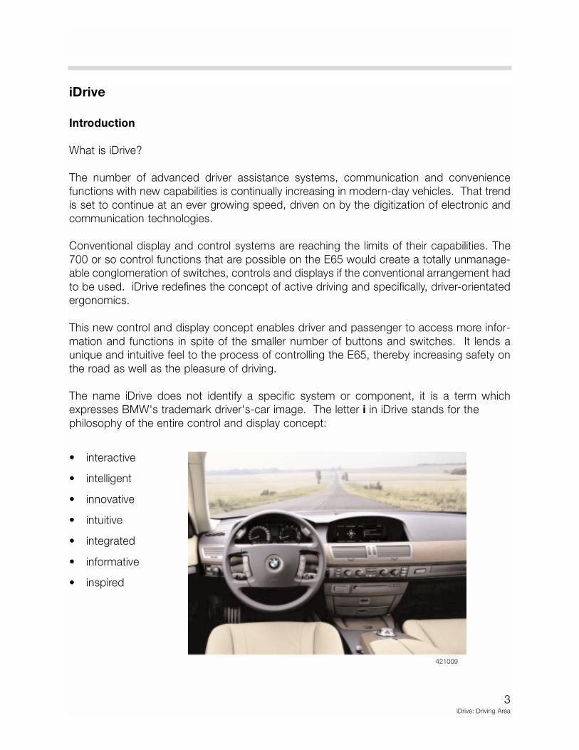
The name iDrive does not identify a specific system or component, it is a term which
expresses BMW's trademark driver's-car image. The letter i in iDrive stands for the
philosophy of the entire control and display concept:
• interactive
• intelligent
• innovative
• intuitive
• integrated
• informative
• inspired
421009
4iDrive: Driving Area
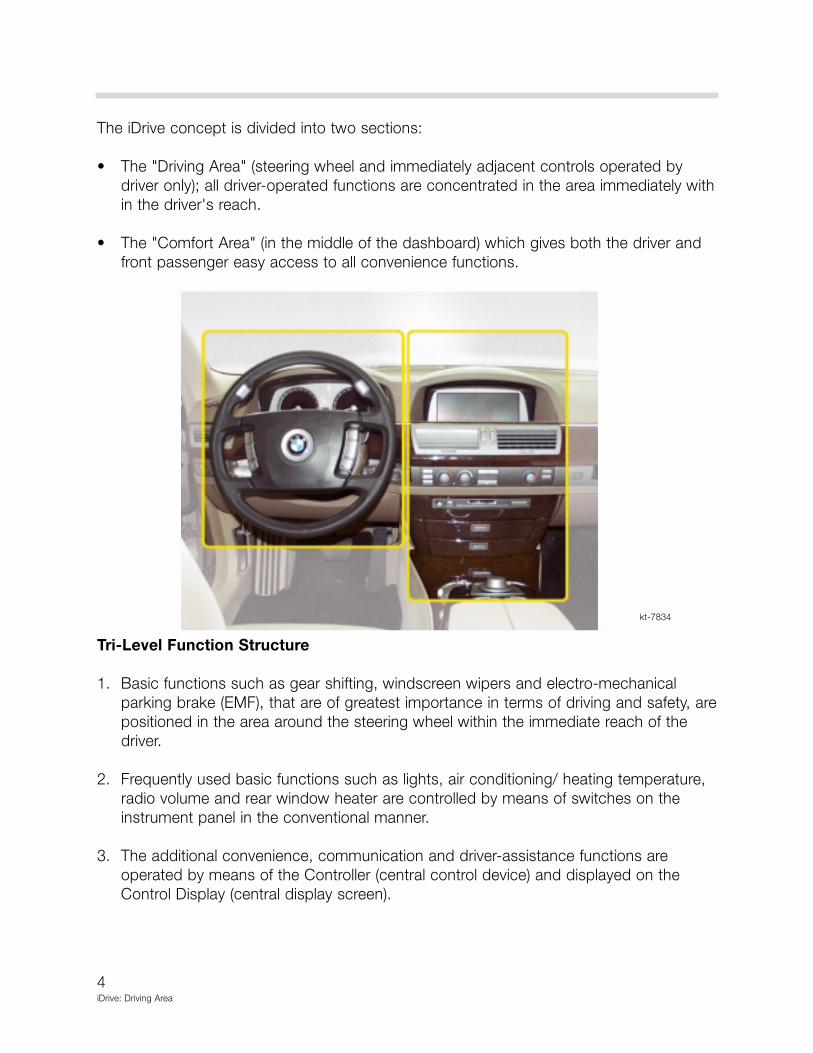
The iDrive concept is divided into two sections:
• The "Driving Area" (steering wheel and immediately adjacent controls operated by
driver only); all driver-operated functions are concentrated in the area immediately with
in the driver's reach.
• The "Comfort Area" (in the middle of the dashboard) which gives both the driver and
front passenger easy access to all convenience functions.
Tri-Level Function Structure
1. Basic functions such as gear shifting, windscreen wipers and electro-mechanical
parking brake (EMF), that are of greatest importance in terms of driving and safety, are
positioned in the area around the steering wheel within the immediate reach of the
driver.
2. Frequently used basic functions such as lights, air conditioning/ heating temperature,
radio volume and rear window heater are controlled by means of switches on the
instrument panel in the conventional manner.
3. The additional convenience, communication and driver-assistance functions are
operated by means of the Controller (central control device) and displayed on the
Control Display (central display screen).
kt-7834
5iDrive: Driving Area
Driving Area
Components
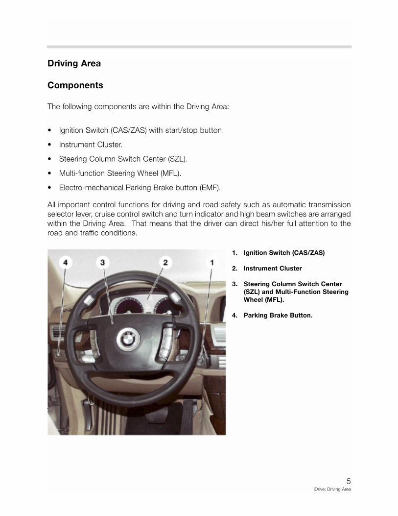
The following components are within the Driving Area:
• Ignition Switch (CAS/ZAS) with start/stop button.
• Instrument Cluster.
• Steering Column Switch Center (SZL).
• Multi-function Steering Wheel (MFL).
• Electro-mechanical Parking Brake button (EMF).
All important control functions for driving and road safety such as automatic transmission
selector lever, cruise control switch and turn indicator and high beam switches are arranged
within the Driving Area. That means that the driver can direct his/her full attention to the
road and traffic conditions.
1. Ignition Switch (CAS/ZAS)
2. Instrument Cluster
3. Steering Column Switch Center
(SZL) and Multi-Function Steering
Wheel (MFL).
4. Parking Brake Button.
6iDrive: Driving Area
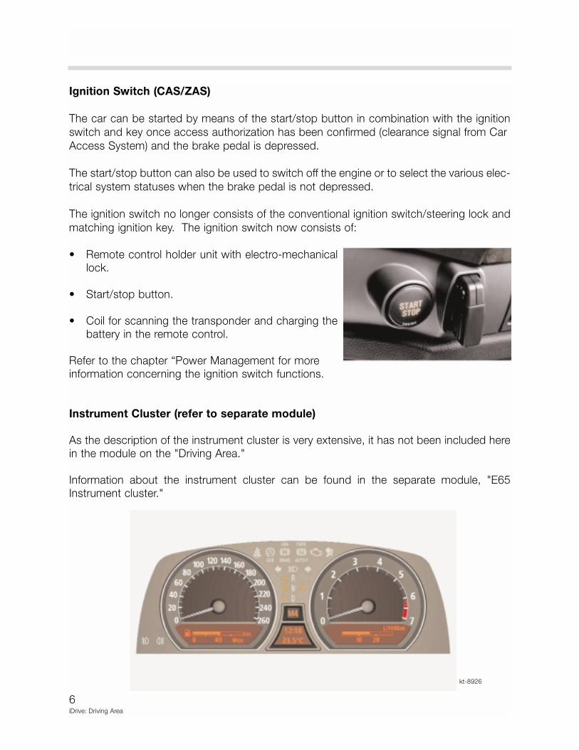
Ignition Switch (CAS/ZAS)
The car can be started by means of the start/stop button in combination with the ignition
switch and key once access authorization has been confirmed (clearance signal from Car
Access System) and the brake pedal is depressed.
The start/stop button can also be used to switch off the engine or to select the various elec-
trical system statuses when the brake pedal is not depressed.
The ignition switch no longer consists of the conventional ignition switch/steering lock and
matching ignition key. The ignition switch now consists of:
• Remote control holder unit with electro-mechanicallock.
• Start/stop button.
• Coil for scanning the transponder and charging thebattery in the remote control.
Refer to the chapter “Power Management for moreinformation concerning the ignition switch functions.
Instrument Cluster (refer to separate module)
As the description of the instrument cluster is very extensive, it has not been included herein the module on the "Driving Area."
Information about the instrument cluster can be found in the separate module, "E65Instrument cluster."
kt-8926
7iDrive: Driving Area
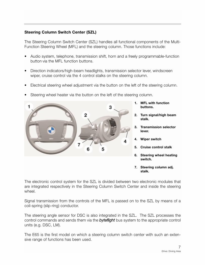
Steering Column Switch Center (SZL)
The Steering Column Switch Center (SZL) handles all functional components of the Multi-
Function Steering Wheel (MFL) and the steering column. Those functions include:
• Audio system, telephone, transmission shift, horn and a freely programmable-function
button via the MFL function buttons.
• Direction indicators/high-beam headlights, transmission selector lever, windscreen
wiper, cruise control via the 4 control stalks on the steering column.
• Electrical steering wheel adjustment via the button on the left of the steering column.
• Steering wheel heater via the button on the left of the steering column.
The electronic control system for the SZL is divided between two electronic modules that
are integrated respectively in the Steering Column Switch Center and inside the steering
wheel.
Signal transmission from the controls of the MFL is passed on to the SZL by means of a
coil-spring (slip-ring) conductor.
The steering angle sensor for DSC is also integrated in the SZL. The SZL processes the
control commands and sends them via the bbyytteefflliigghhtt bus system to the appropriate control
units (e.g. DSC, LM).
The E65 is the first model on which a steering column switch center with such an exten-
sive range of functions has been used.
1. MFL with function
buttons.
2. Turn signal/high beam
stalk.
3. Transmission selector
lever.
4. Wiper switch
5. Cruise control stalk
6. Steering wheel heating
switch.
7. Steering column adj.
stalk.
8iDrive: Driving Area
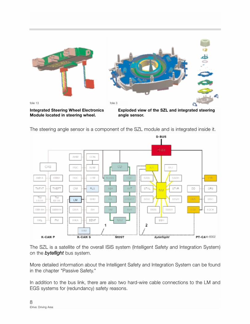
The steering angle sensor is a component of the SZL module and is integrated inside it.
The SZL is a satellite of the overall ISIS system (Intelligent Safety and Integration System)
on the bbyytteefflliigghhtt bus system.
More detailed information about the Intelligent Safety and Integration System can be found
in the chapter "Passive Safety."
In addition to the bus link, there are also two hard-wire cable connections to the LM and
EGS systems for (redundancy) safety reasons.
kt-8302
folie 13 folie 3
Integrated Steering Wheel Electronics Exploded view of the SZL and integrated steering
Module located in steering wheel. angle sensor.
LM
9iDrive: Driving Area
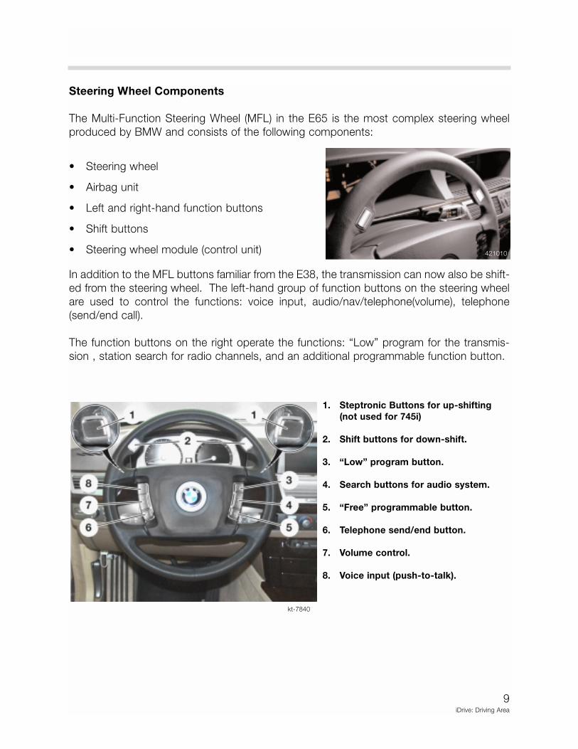
Steering Wheel Components
The Multi-Function Steering Wheel (MFL) in the E65 is the most complex steering wheel
produced by BMW and consists of the following components:
• Steering wheel
• Airbag unit
• Left and right-hand function buttons
• Shift buttons
• Steering wheel module (control unit)
In addition to the MFL buttons familiar from the E38, the transmission can now also be shift-
ed from the steering wheel. The left-hand group of function buttons on the steering wheel
are used to control the functions: voice input, audio/nav/telephone(volume), telephone
(send/end call).
The function buttons on the right operate the functions: “Low” program for the transmis-
sion , station search for radio channels, and an additional programmable function button.
421010
1. Steptronic Buttons for up-shifting
(not used for 745i)
2. Shift buttons for down-shift.
3. “Low” program button.
4. Search buttons for audio system.
5. “Free” programmable button.
6. Telephone send/end button.
7. Volume control.
8. Voice input (push-to-talk).
kt-7840
10iDrive: Driving Area
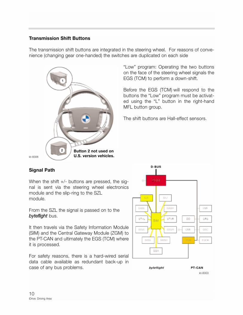
Transmission Shift Buttons
The transmission shift buttons are integrated in the steering wheel. For reasons of conve-
nience (changing gear one-handed) the switches are duplicated on each side
“Low” program: Operating the two buttons
on the face of the steering wheel signals the
EGS (TCM) to perform a down-shift.
Before the EGS (TCM) will respond to the
buttons the “Low” program must be activat-
ed using the “L” button in the right-hand
MFL button group.
The shift buttons are Hall-effect sensors.
Signal Path
When the shift +/- buttons are pressed, the sig-
nal is sent via the steering wheel electronics
module and the slip-ring to the SZL
module.
From the SZL the signal is passed on to the
bbyytteefflliigghhtt bus.
It then travels via the Safety Information Module
(SIM) and the Central Gateway Module (ZGM) to
the PT-CAN and ultimately the EGS (TCM) where
it is processed.
For safety reasons, there is a hard-wired serial
data cable available as redundant back-up in
case of any bus problems.
kt-8306
kt-8303
Button 2 not used on
U.S. version vehicles.
11iDrive: Driving Area
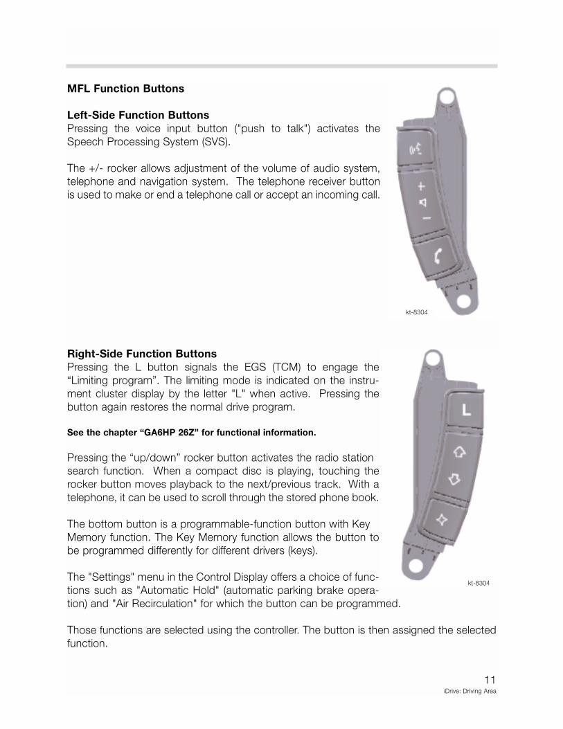
MFL Function Buttons
Left-Side Function Buttons
Pressing the voice input button ("push to talk") activates the
Speech Processing System (SVS).
The +/- rocker allows adjustment of the volume of audio system,
telephone and navigation system. The telephone receiver button
is used to make or end a telephone call or accept an incoming call.
Right-Side Function Buttons
Pressing the L button signals the EGS (TCM) to engage the
“Limiting program”. The limiting mode is indicated on the instru-
ment cluster display by the letter "L" when active. Pressing the
button again restores the normal drive program.
See the chapter “GA6HP 26Z” for functional information.
Pressing the “up/down” rocker button activates the radio station
search function. When a compact disc is playing, touching the
rocker button moves playback to the next/previous track. With a
telephone, it can be used to scroll through the stored phone book.
The bottom button is a programmable-function button with Key
Memory function. The Key Memory function allows the button to
be programmed differently for different drivers (keys).
The "Settings" menu in the Control Display offers a choice of func-
tions such as "Automatic Hold" (automatic parking brake opera-
tion) and "Air Recirculation" for which the button can be programmed.
Those functions are selected using the controller. The button is then assigned the selected
function.
kt-8304
kt-8304
12iDrive: Driving Area
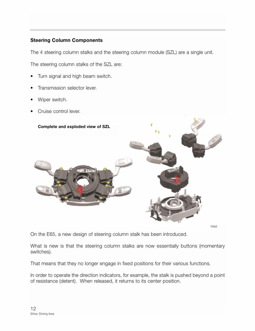
Steering Column Components
The 4 steering column stalks and the steering column module (SZL) are a single unit.
The steering column stalks of the SZL are:
• Turn signal and high beam switch.
• Transmission selector lever.
• Wiper switch.
• Cruise control lever.
On the E65, a new design of steering column stalk has been introduced.
What is new is that the steering column stalks are now essentially buttons (momentaryswitches).
That means that they no longer engage in fixed positions for their various functions.
In order to operate the direction indicators, for example, the stalk is pushed beyond a pointof resistance (detent). When released, it returns to its center position.
folie2
Complete and exploded view of SZL

13iDrive: Driving Area
Turn signal, High beam, BC and CC Switch
The turn signal and high beam switch is a
button (momentary switch) that is used to
operate the high beam, direction indica-
tors and to switch on the parking lights.
The turn signal switch incorporates two
axial (push button) switches for the On-
Board Computer displays.
The top switch (2) activates the board
computer display on the instrument cluster below the tachometer. This shows information
such as average fuel consumption and average speed. The lower switch (1) activates the
On-Board Computer display on the instrument cluster below the speedometer. This shows
information such as fuel level and range.
Automatic cancelling of the turn signals is controlled by the signal from the steering angle
sensor. The SZL sends the command via the bus system to the light module (LM) where it
is converted.
Brief operation of the turn signals can be accomplished by touching the stalk as far as (but
not beyond) the point of resistance.
The parking light function is switched on by pressing the stalk beyond the point of resis-
tance when the ignition is off. The function is cancelled by pressing the stalk in the
opposite direction.
To switch the high beam “ON”, the stalk is tapped forwards, and to switch high beam “OFF”
or flash the headlights, it is tapped backwards. When the driver operates the turn signal or
high beam switch, a message is sent to the light module.
The signal travels from the SZL via the bbyytteefflliigghhtt bus to the SIM. From there is passes to
the ZGM and onto the K-CAN SYSTEM and the light module (LM).
The light module simultaneously analyzes a redundant back-up signal from the SZL. This
is transmitted via a separate lead. This means that the signal is independent of the K-CAN
SYSTEM and the bbyytteefflliigghhtt bus.
The purpose of this duplication is to ensure vehicle safety. Even if the bus systems fail, the
functions can still be operated.
kt-8357
14iDrive: Driving Area
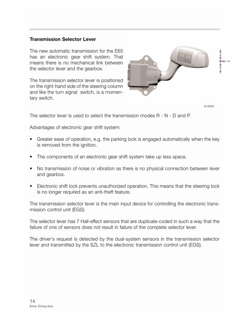
Transmission Selector Lever
The new automatic transmission for the E65
has an electronic gear shift system. That
means there is no mechanical link between
the selector lever and the gearbox.
The transmission selector lever is positioned
on the right-hand side of the steering column
and like the turn signal switch, is a momen-
tary switch.
The selector lever is used to select the transmission modes R - N - D and P.
Advantages of electronic gear shift system:
• Greater ease of operation, e.g. the parking lock is engaged automatically when the key
is removed from the ignition.
• The components of an electronic gear shift system take up less space.
• No transmission of noise or vibration as there is no physical connection between lever
and gearbox.
• Electronic shift lock prevents unauthorized operation. This means that the steering lock
is no longer required as an anti-theft feature.
The transmission selector lever is the main input device for controlling the electronic trans-
mission control unit (EGS).
The selector lever has 7 Hall-effect sensors that are duplicate-coded in such a way that the
failure of one of sensors does not result in failure of the complete selector lever.
The driver's request is detected by the dual-system sensors in the transmission selector
lever and transmitted by the SZL to the electronic transmission control unit (EGS).
kt-8358
15iDrive: Driving Area
The EGS checks that the gear shift is permissible and initiates the operation via the elec-
tronic-hydraulic control unit that is integrated in the automatic gearbox.
The currently selected gear and any Check Control messages such as "Press brake pedal
to engage gear" are displayed on the instrument cluster for the information of the driver.
The selector lever signals are not carried out unless the EGS has received a clearance sig-
nal from the Car Access System (CAS). That means that an authorized key must have been
detected in the holder unit of the ignition switch. If the key is removed from the ignition, the
parking lock is automatically engaged.
The gear shift "gate" pattern on the selector lever is fitted with locator lighting (controlled by
terminal 58g).
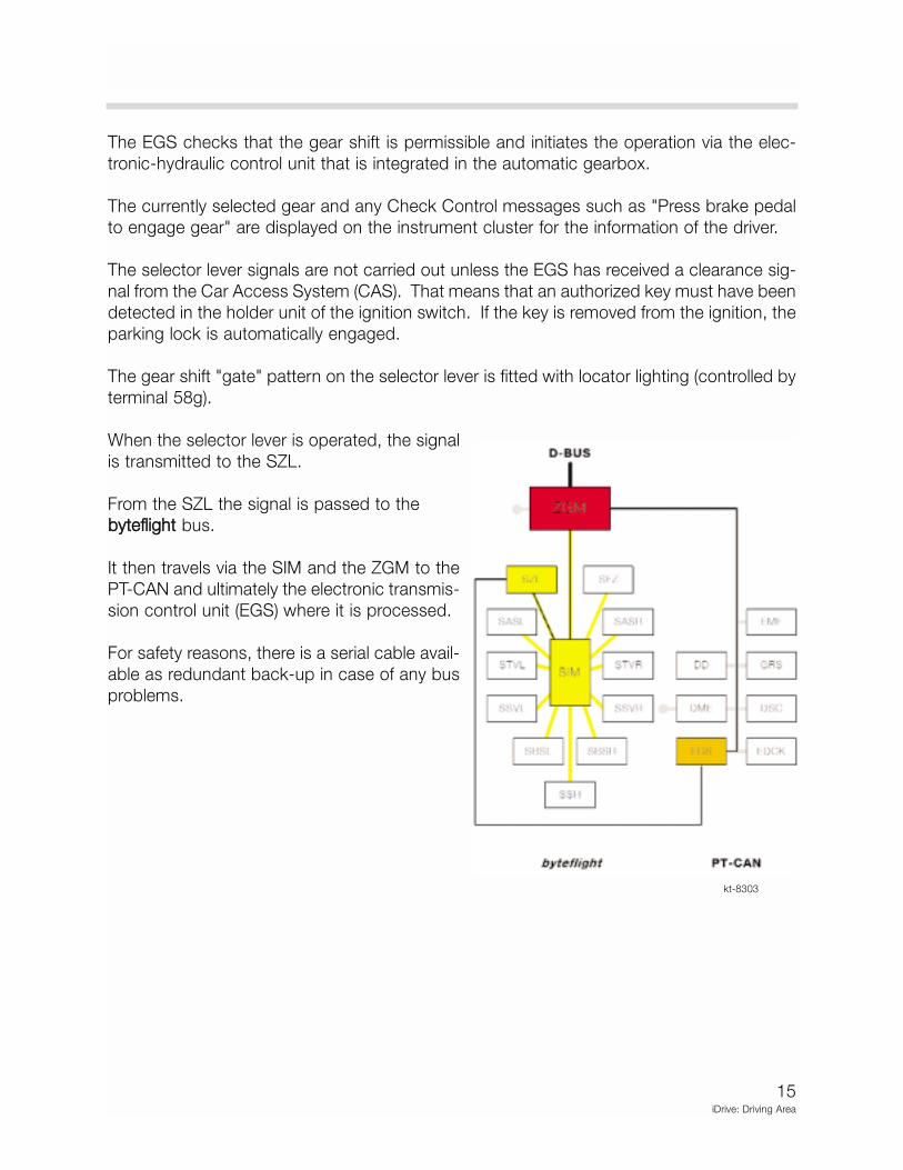
When the selector lever is operated, the signal
is transmitted to the SZL.
From the SZL the signal is passed to the
bbyytteefflliigghhtt bus.
It then travels via the SIM and the ZGM to the
PT-CAN and ultimately the electronic transmis-
sion control unit (EGS) where it is processed.
For safety reasons, there is a serial cable avail-
able as redundant back-up in case of any bus
problems.
kt-8303

16iDrive: Driving Area
Wiper Switch
The wiper switch is also a momentary
switch. It does not engage in fixed posi-
tions for its various functions.
The control concept incorporates a
sequential mode. That means that the
wiper speed settings are selected by
tapping the stalk repeatedly the required
number of times in the desired direction.
The wiper switch also incorporates an axial (push-button) switch (1). The Rain/Light sensor
(RLS), system is switched on and off by this switch. The function is indicated by an LED (3).
When the ignition is switched “OFF”, the wiper and the rain sensor are switched off at the
same time.
The rain sensor is activated by means of the push-button switch on the wiper stalk. The
LED then lights up.
When the rain sensor is switched on, the windscreen wipers are controlled automatically
according to how much precipitation (rain or snow) is on the windscreen.
That includes switching them on and off and selecting the required setting from intermittent
to continuous wipe. The rain sensor is switched off by touching the push-button switch
again or automatically when the ignition is switched OFF.
The adjuster wheel sets the sensitivity of the rain sensor to a choice of 4 levels.
kt-8359
17iDrive: Driving Area
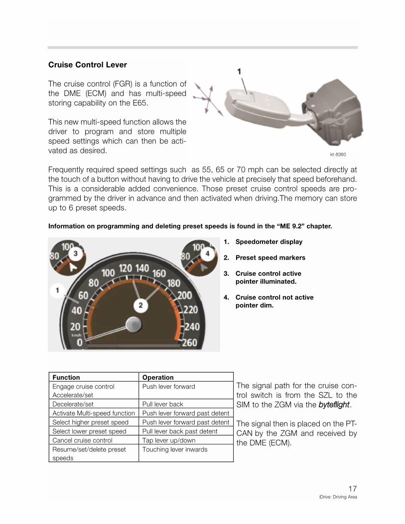
Cruise Control Lever
The cruise control (FGR) is a function of
the DME (ECM) and has multi-speed
storing capability on the E65.
This new multi-speed function allows the
driver to program and store multiple
speed settings which can then be acti-
vated as desired.
Frequently required speed settings such as 55, 65 or 70 mph can be selected directly at
the touch of a button without having to drive the vehicle at precisely that speed beforehand.
This is a considerable added convenience. Those preset cruise control speeds are pro-
grammed by the driver in advance and then activated when driving.The memory can store
up to 6 preset speeds.
Information on programming and deleting preset speeds is found in the “ME 9.2” chapter.
The signal path for the cruise con-
trol switch is from the SZL to the
SIM to the ZGM via the bbyytteefflliigghhtt.
The signal then is placed on the PT-
CAN by the ZGM and received by
the DME (ECM).
kt-8360
1. Speedometer display
2. Preset speed markers
3. Cruise control active
pointer illuminated.
4. Cruise control not active
pointer dim.
Function Operation
Engage cruise control
Accelerate/set
Push lever forward
Decelerate/set Pull lever back
Activate Multi-speed function Push lever forward past detent
Select higher preset speed Push lever forward past detent
Select lower preset speed Pull lever back past detent
Cancel cruise control Tap lever up/down
Resume/set/delete preset
speeds
Touching lever inwards
18iDrive: Driving Area
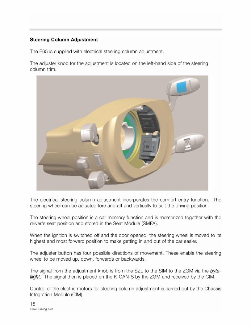
Steering Column Adjustment
The E65 is supplied with electrical steering column adjustment.
The adjuster knob for the adjustment is located on the left-hand side of the steering
column trim.
The electrical steering column adjustment incorporates the comfort entry function. The
steering wheel can be adjusted fore and aft and vertically to suit the driving position.
The steering wheel position is a car memory function and is memorized together with the
driver's seat position and stored in the Seat Module (SMFA).
When the ignition is switched off and the door opened, the steering wheel is moved to its
highest and most forward position to make getting in and out of the car easier.
The adjuster button has four possible directions of movement. These enable the steering
wheel to be moved up, down, forwards or backwards.
The signal from the adjustment knob is from the SZL to the SIM to the ZGM via the bbyyttee--
fflliigghhtt. The signal then is placed on the K-CAN-S by the ZGM and received by the CIM.
Control of the electric motors for steering column adjustment is carried out by the Chassis
Integration Module (CIM)

19iDrive: Driving Area
Steering Wheel Heater Switch
The steering wheel heater is switched on by a button on the left-hand side of the steering
column between the two steering column stalks.
It can be switched on provided the electrical system status is at least terminal 15. An LED
on the switch indicates when the steering wheel heater is on.
The steering wheel heater consists of a coil heater element in the steering wheel rim.
A temperature sensor (PTC sensor) in the steering wheel sends the temperature signal back
to the steering wheel electronics module.
Operation of the steering wheel heating is explained in the “Central Body Electronics” Chapter.
kt-8353
20iDrive: Driving Area
Electro-Mechanical Parking Brake Button
The parking brake is an automated electro-mechanical parking brake system (EMF) intro-
duced for the first time on the E65.
When the engine is running, the parking brake system operates the front and rear disc
brakes via the brake hydraulics. When the engine is switched off, the parking brake is oper-
ated by an electro-mechanical system. Two cables are then used to actuate the rear park-
ing brake drums.
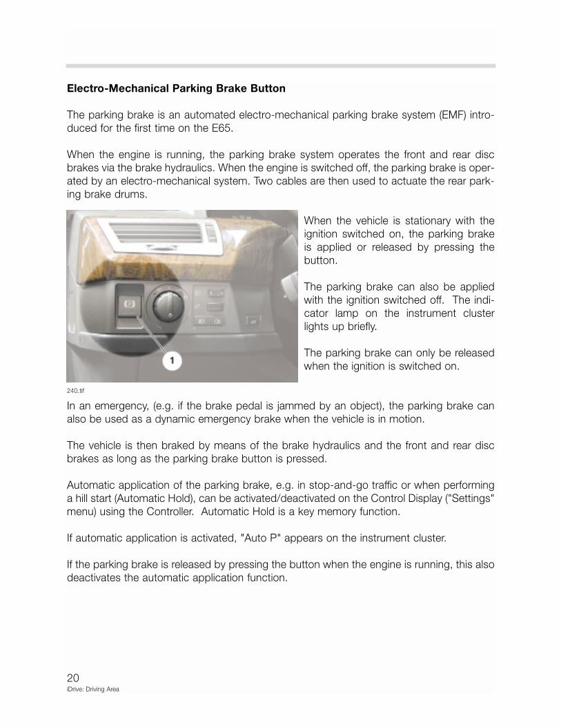
When the vehicle is stationary with the
ignition switched on, the parking brake
is applied or released by pressing the
button.
The parking brake can also be applied
with the ignition switched off. The indi-
cator lamp on the instrument cluster
lights up briefly.
The parking brake can only be released
when the ignition is switched on.
In an emergency, (e.g. if the brake pedal is jammed by an object), the parking brake can
also be used as a dynamic emergency brake when the vehicle is in motion.
The vehicle is then braked by means of the brake hydraulics and the front and rear disc
brakes as long as the parking brake button is pressed.
Automatic application of the parking brake, e.g. in stop-and-go traffic or when performing
a hill start (Automatic Hold), can be activated/deactivated on the Control Display ("Settings"
menu) using the Controller. Automatic Hold is a key memory function.
If automatic application is activated, "Auto P" appears on the instrument cluster.
If the parking brake is released by pressing the button when the engine is running, this also
deactivates the automatic application function.
240.tif
21iDrive: Driving Area
Review Questions
1. List the controls found within the driver area of iDrive.
2. How many control modules make up the Steering Column Switch Center (SZL)?
3. Which functions of the SZL use a redundant hardwired-data cable for plausibility and
safety?