Embed Size (px)
Citation preview

Initial Print Date: 10/01 Revision Date: 11/01
Subject Page
Introduction. . . . . . . . . . . . . . . . . . . . . . . . . . . . . . . . . . . . . . . . . . . . . . 3
Bus Systems. . . . . . . . . . . . . . . . . . . . . . . . . . . . . . . . . . . . . . . . . . . . . 3
E65 Bus System Overview. . . . . . . . . . . . . . . . . . . . . . . . . . . . . . . . . . . 6
E65 Sub-Bus Systems. . . . . . . . . . . . . . . . . . . . . . . . . . . . . . . . . . . . . . 7
Gateways. . . . . . . . . . . . . . . . . . . . . . . . . . . . . . . . . . . . . . . . . . . . . . . 10
Controller Area Network (CAN Bus). . . . . . . . . . . . . . . . . . . . . . . . . . . . .16
E65 K-CAN. . . . . . . . . . . . . . . . . . . . . . . . . . . . . . . . . . . . . . . . . . . 16
PT-CAN. . . . . . . . . . . . . . . . . . . . . . . . . . . . . . . . . . . . . . . . . . . . . . 20
Fiber-Optic Bus Lines. . . . . . . . . . . . . . . . . . . . . . . . . . . . . . . . . . . . . . .21
Fiber-Optic use in the E65. . . . . . . . . . . . . . . . . . . . . . . . . . . . . . . . . . . 28
MOST Bus. . . . . . . . . . . . . . . . . . . . . . . . . . . . . . . . . . . . . . . . . . . . . . 31
Byteflight. . . . . . . . . . . . . . . . . . . . . . . . . . . . . . . . . . . . . . . . . . . . . . . .45
Diagnosis Bus. . . . . . . . . . . . . . . . . . . . . . . . . . . . . . . . . . . . . . . . . . . . 49
Review Questions. . . . . . . . . . . . . . . . . . . . . . . . . . . . . . . . . . . . . . . . . 51
Table of Contents
E65 BUS SYSTEMS

2E65 Bus Systems
E65 BUS SYSTEMS
Model: E65 - 745i
Production Date: 11/2001- Start of Production
Objectives:
After completing this module you should be able to:
• Identify the various bus systems used in the E65.
• Define the purpose of a “Gateway” module.
• Describe the structure of the various bus systems.
• Explain the purpose of Terminal Resistors in the CAN bus.
• Understand the reason why fiber-optic bus systems are used in the E65.
• Describe how fiber-optic cables can be damaged due to improper handling.

3Bus Systems
Introduction
The safety and comfort of vehicles are continually advancing. Legal requirements relating to
fuel consumption and exhaust emissions can now only be met by the use of more elec-
tronic components (e.g. control units, actuators and sensors) in vehicles.
Processes controlled by individual control units are increasingly being linked to one anoth-
er via bus systems. That means that the processes are shared together and control units
interact with one another in a coordinated manner.
As a result, the exchange of data across the vehicle's electrical system is increasing rapid-
ly and because of that exchange of information, many new functions are being made
possible. The consequences of this trend are greater vehicle safety,
superior ride comfort and improved fuel economy. However, such continuing advances can
no longer be achieved with conventional electrical systems.
Limits of Conventional Electrical Systems
The increasing amount of desirable electronic components in cars is limited by a number
of factors. These factors include:
• Increasing complexity of wiring systems
• Higher production costs
• Increasing demands on available space in the vehicle
• Extreme complexity of component configuration
• Reduced reliability of the overall system
In order to minimize such disadvantages, bus systems are now being used for the vehicle's
electrical system.
Bus systems
Bus systems enable the individual control units on the vehicle to be networked with one
another via "serial interfaces." The use of bus systems in vehicle electrical systems provides
a number of advantages.

4E65 Bus Systems
Advantages of Bus Systems
• Greater reliability of the overall system
• Simplification of wiring systems
• Reduction of the number of separate cables
• Reduction of the cross-sectional areas of wiring looms
• Greater versatility in terms of cable routing
• Multiple use of sensors in the vehicle, thereby reducing the number of duplicated
sensors
• Use of shared interfaces by signals, thereby reducing the number of interfaces
• Transmission of complex data
• Greater flexibility in the event of system modifications
• Data volume can be expanded at any time
• Flexible configuration of control units
• Adoption of new functions for customers
• Efficient diagnosis
• Lower hardware costs
The E65 introduces three (3) new bus systems. Two of them are based on fiber-optic tech-
nology. The two new fiber-optic bus systems are called:
MOST bus (Media Orientated System Transport) and " byteflight" (safety systems bus).
The third bus system consists of two insulated copper twisted-pair wires and is called the:
K-CAN (Body-Controller Area Network). The K-CAN bus replaces the single wire K bus
(body bus) and is subdivided into two sections: the K-CAN System and the K-CAN
Periphery.
The powertrain control units continue to use a CAN bus called the PT-CAN, except that
now it is a three wire bus to include a KL-15 wake-up wire.
Comparison of E38 and E65 bus systems
E38 E65
CAN PT-CAN
I-Bus
K-Bus K-CAN System
P-Bus K-CAN Periphery
------- MOST Bus
------- byteflight
D-Bus D-bus

5E65 Bus Systems
Bus Communication Speeds
The communication speed of the busses in the E65 have been increased significantly to
handle the demand placed on them by a greater number of control units.
Here is a comparison between the busses of the E38 and the E65.
Model Bus Data Rate Structure
E38 I/K/P Bus 9.6Kbps linear
CAN 500Kbps linear
D-Bus 9.6Kbps linear
E65/E66 K-CAN-S 100Kbps linear
K-CAN-P 100Kbps linear
PT-CAN 500Kbps linear
MOST 22.5Mbps ring
byteflight 10Mbps star
Sub-Busses 9.6Kbps linear
D-Bus 115Kbps linear

6E65 Bus Systems
E65 BUS SYSTEM
KT-7323

7E65 Bus Systems
E65 Sub-Bus Systems
In addition to the bus systems, sub-bus systems are also used. These are subordinate ser-
ial bus systems. Their functions correspond to those of the previous I/K bus.
The following sub-bus systems are fitted on the E65:
• Driver's door P bus (driver's door switch block periphery bus)
• Engine LoCAN (engine Low CAN bus; link between DME and Valvetronic control unit)
• Telcommander CAN (Phone board CAN)
• M bus (air-conditioning motor bus)
• DWA K bus (alarm system body bus)
• BSD interface (bit-serial data interface)
Driver’s Door P-Bus
The driver's door P bus passes the signals from the driver's-door switch block to the door
module (e.g. functions window lift, child lock-out request, Sun shade).
KT-7327
P-Bus

8E65 Bus Systems
Engine LoCAN
The Engine LoCAN enables communication between the DME and the Valvetronic control
unit.
TelCommander CAN
The TelCommander CAN provides the link to the telephone control panel module. It is a
two-wire cable.
KT-7329
KT-7335

9E65 Bus Systems
M-Bus
The M bus enables control of the various motors for the air conditioning system.
DWA K-Bus
The functions of the alarm system are split between the two control units (DWA and SINE).
The alarm system K bus enables communication between those two control units.
KT-7330
KT-7325

10E65 Bus Systems
BSD
Communication via the BSD enables adjustment of the battery charging voltage, and com-
munication between the DME and oil quality sensor for example.
Gateways
Introduction
A gateway (GW) is an interface. It connects different bus systems within the vehicle's elec-
trical system. It provides a means of ensuring the exchange of information in spite of
differences in the rates of data transmission on the individual bus systems. Diagnostic
access to the individual control units from a central point is made possible by the gateway.
The gateway modules used in the E65 are the Car Access System (CAS), Control Display
(MCGW-MOST/CAN gateway) and the Central Gateway Module (ZGM).
Method of Operation
The data transmitted by the various bus systems is received by the gateway. At this point,
transmission rates, data and priority levels of the individual messages are filtered and tem-
porarily stored if necessary. This requires a non-volatile memory.
KT-7324

11E65 Bus Systems
Using gateway rules and conversion tables, the gateway converts the messages as
required by the various bus systems concerned. The messages are then passed to the var-
ious bus systems via which they reach their ultimate destinations (recipient control unit). If
necessary, messages that are relatively less important are held in the gateway's memory
and sent later.
KL-15 wake-up
KT-8136
Overview of E65 gateways
KT-8293

12E65 Bus Systems
Examples of the Function of the Central Gateway Module (ZGM)
The DME and DSC control units both place mes-
sages on the PT-CAN. Those messages are
received by the Central Gateway Module from
the PT-CAN. The buffer memory on the Central
Gateway Module temporarily stores the mes-
sages from the PT-CAN.
They are converted by the Central Gateway
Module according to specific gateway rules and
conversion tables for the K-CAN System Bus.
As the K-CAN System Bus is slower than the PT-
CAN, the two messages are joined together and are sent out as one message. The mes-
sages reach their destinations (IHKA/Kombi) via the K-CAN SYSTEM bus.
Electronic Fuel Pump Control
The DME calculates the delivery rate of fuel required on the basis of the vehicle's operating
status. The figure calculated is sent in the form of a message to the SBSR (right B-pillar
satellite).
The original message (PT-CAN signal) is converted by the ZGM to a byteflight message
(fibre-optic signal). From the ZGM, the message is passed via the byteflight to the SIM,
which passes it to the SBSR.
The electronic evaluation unit integrated in the SBSR converts the signal to a PWM signal.
That PWM signal controls the electronic fuel pump (EKP). The required fuel delivery rate can
now be provided by the electronic fuel pump.
ZGM Buffer memory
Out going mes-
sage on K-CAN
DSC
DME
2 incoming messages
via the PT-CAN.
KT-7872

13E65 Bus Systems
Windscreen Wiper Function
The driver operates the windscreen wiper switch (SWS) to initiate a wiper system function.
The wiper switch is plugged directly into the Steering Column Switch Center Module (SZL).
The SZL module analyzes the signals from the wiper switch and calculates which wiper sys-
tem function has been selected by the driver. That information is placed on the byteflight in
the form of a message.
The Safety Information Module (SIM) receives the driver's instruction from the SZL and
passes it on to the ZGM via the byteflight. The ZGM receives the message from the SIM
and passes it on in its role as "gateway control unit" to the Wiper Module (WIM) via the K-
CAN S. The wiper module performs the action requested by the driver (e.g. wipe or wash).
Optimum Charging Controlled by Power Module (PM)
In order to drain as little energy as possible from the battery (particularly in the winter), the
idling speed is increased at an early stage. This ensures that the battery charge level is kept
high. If the charge level falls below the minimum required to be able to start the car, the
idling speed is increased.
The PM detects that the battery charge level is low and places a message to that effect on
the K-CAN P. The Car Access System (CAS) passes the message on to the K-CAN S. The
ZGM receives the message from the CAS and passes it on via the PT CAN in its role of
"gateway control unit".
The DME module receives the request to increase the engine speed over the PT-CAN. The
DME passes that request on via the LoCAN to the Valvetronic control unit (VVT). The
Valvetronic control unit controls the output stage for the valvetronic motors to increase the
engine idle speed accordingly.
KT-8527
KT-8529

14E65 Bus Systems
Examples of CAS Gateway Function
Seat Adjustment
The driver operates the seat adjustment switch. The command is processed by the switch
block and passed via a 3-core data line to the Center Console Control Center Module
(BZM). The BZM places the message on the K-CAN S for the Car Access System (CAS).
The CAS passes the message on in its role as "gateway control unit" to the driver's seat
module (SMFA) via the K-CAN P. The seat module activates the required seat adjustment
motor via its output stages.
Electric Windows (FH) and Sunroof (SHD)
Using the convenience open function, the windows and sunroof can be opened by press-
ing the open button on the remote control. The commands from the remote control are
received by the Car Access System (CAS).
The CAS places the message on the K-CAN P and the K-CAN S. All 4 door modules
(TM...) receive their messages from the K-CAN P, while the sunroof receives its message
from the K-CAN S. The modules then activate their output stages to open the windows and
sunroof. If the button on the remote control is released while the operation is still in
progress, it is then immediately halted. In order to re-activate the convenience open/close
function, the appropriate button on the remote control has to be pressed again.
KT-8525
KT-8531
K-CAN S K-CAN P

15E65 Bus Systems
Example of CD Gateway Function
PDC
The audible PDC warning is output via the audio system speakers. If the car gets close to
an obstacle when the PDC is active, this is signalled by the relevant sensor to the PDC
control unit via the bi-directional data line. The PDC control unit calculates the distance from
the obstacle and places that information on the K-CAN S.
The Control Display (CD) receives the message and passes it on in its role as "gateway con-
trol unit" to the MOST bus. The Audio System Controller (ASK) receives the message from
the CD and calculates from it the required signal tone and frequency. On the basis of that
calculation, the ASK activates the mid-range speaker in the appropriate corner of the vehi-
cle. The audible signal is superimposed (mixed) over the current audio sound (radio, CD,
etc.).
KT-8532

16E65 Bus Systems
Controller Area Network (CAN Bus)
Introduction
The CAN bus is a serial communications bus in which all connected control units can send
as well as receive information. Data exchanges over a CAN operate at a rate of 100 to
500Kbps.
The CAN protocol was originally developed by Robert Bosch GMbH and the Intel corpora-
tion in 1988 for use in the automotive electronics industry to provide a standardized, reli-
able and cost-effective communications bus.
The CAN bus was originally introduced on BMW automobiles in 1992 740i/iL as a data link
between the DME and AGS control units.
E65 K-CAN
Introduction
For the E65, the functions that were incorporated within the main bodyshell electrical sys-
tem on the E38 have been distributed among a number of separate control units. Those
control units and various new control units are connected to the K-CAN.
The K-CAN is a new development and is subdivided into two sections, the K-CAN System
and the K-CAN Peripherals.
Examples of new control units and functions on the K-CAN are the Car Access System
(CAS), the Centre Console Control Center module (BZM), the Rear Centre Console Control
Center module (BZMF) and the Power Module (PM).
K-CAN System/Peripherals
The subdivision of the K-CAN into the sections "SYSTEM" and "PERIPHERALS" relieves
the load on the bus because the number of vehicle components (control units/modules) is
divided between two "independent" bus systems.

17E65 Bus Systems
Advantages of two K-CAN Busses
• In a crash, it is possible that components could fail as a result of a short circuit on the
K-CAN. The K-CAN Peripherals covers such at-risk areas. If the K-CAN Peripherals
were to fail, the K-CAN System would still remain functional.
• Addition of new vehicle components to either bus is possible at any time. (Maximum 40
control units per bus)
• Low data load on the bus system from bus users due to division into two sections.
• Greater reliability.
KT-7805

18E65 Bus Systems
Voltage Level on the K-CAN.
If the CAN High voltage level changes from low to high, this represents a logical 1. If the
voltage level changes back to low, this represents a logical 0. The voltage level on the CAN
is in the range of 1V to 5V.
Note:
The voltage can alter as a result of a defective terminal resistor, for example. This has an effect on
the CAN system. Communication between bus nodes no longer functions properly.
Terminal Resistor
An electrical conductor through which current passes always has an ohmic, an inductive
and a capacitive impedance. When data is transmitted from point "A" to point "B" over a
CAN line, the total sum of that impedance has an effect on the transmission of that data.
The higher the transmission frequency, the greater the effect of the inductive and capaci-
tive impedance. The result of this can be that when the signal reaches the end of the data
transmission line, it is unidentifiable. For that reason, the data line is "modified" by terminal
resistors so as to preserve the original signal.
The inductive impedance is produced by phenomena such as the coil effect of the wire. The
capacitive impedance for example is produced by the effect of routing the wire parallel to
the vehicle body. The terminal resistors on a bus system vary. They are generally depen-
dent on the following parameters:
• Frequency of data transmission on the bus system.
• Inductive/capacitive load on the transmission channel.
• Length of the data transmission cable (The longer the cable is, the greater is the
inductive component).
TimeKT-6875
KT-6876

19E65 Bus Systems
The control units are categorized either as basic control units or other control units.
Categorization is performed on the basis of the impedance level. Basic control units are
those which always have to be fitted in the car regardless of equipment level or market.
Other control units are those that are dependent on the options fitted.
The terminal resistor values for the K-CAN system
are 820 Ohm for “Basic” controllers and 12K Ohms
for all other control units.
For the E65 the Basic controllers are:
K-CAN S: LM, IHKA, CAS, CD, ZGM, KOMBI.
K-CAN P: CAS, TMFAT, TMBFT, HKL
The resistors are located inside of the control units.
Wake-Up on the K-CAN
The control units on the K-CAN network are "awakened" via the bus. For that reason, it
has been possible to dispense with the previous function of terminal 15 as wake-up line.
The wake-up message is passed directly to the control unit output stage by the CAS mod-
ule receiver. The output stage switches terminal 30 on and the unit is woken up.
KT-7228
Terminal Resistors
for K-CAN

20E65 Bus Systems
PT (Powertrain) CAN
Introduction
The PT CAN is the fastest CAN bus in the E65. It is an existing bus system. PT CAN
stands for powertrain CAN. It links all control units/modules associated with the power-
train. All the bus nodes are connected in parallel with one another. In contrast with the pre-
vious bus, (two-core twisted pair) it now has three wires. The third wire of the bus cable is
used as the wake-up line and has nothing to do with the actual CAN bus function.
Voltage Level on the PT CAN
When the bus is inactive, the bus high and low
levels are at 2.5 V.
When the bus becomes active, the CAN Low
voltage level changes to low (1.5 V) and the
CAN High level changes to high (4 V), thus rep-
resenting logical 1.
PT CAN Terminal Resistors
The PT CAN uses two terminal resistors to establish the correct inductive and capacitive
impedance in the communication lines. Two 120 Ohm resistors are located in the wire har-
ness (no longer in the control units as on previous systems). The resistors are located:
• Behind the right front kick-panel
trim. (A-pillar)
• Below the rear seat.
The resistance is measured by con-
necting the appropriate adapter to any
of the modules on the PT-CAN and
measuring resistance between CAN-H
and CAN-L.
The measured resistance should be
close to 60 Ohms.
KT-7333
External Resistors
KT-8313

21E65 Bus Systems
Failsafe Characteristics
If the PT CAN goes into emergency mode it is no longer available for the engine control sys-
tem. However, it can still provide communication between the other bus nodes even if:
• One of the CAN leads (cores) is broken- one of the CAN leads (cores) is shorting to
ground.
• One of the CAN leads (cores) is shorting to the power supply B+.
"Wake-up" Lead in PT CAN Network
The PT CAN for the E65 is now a three wire CAN, the third wire is a hard wire KL-15 sig-
nal used to wake up the powertrain control units. The "wake-up" lead has nothing to do
with the actual PT CAN function. A wake-up telegram is still transmitted by the CAS via the
ZGM - PT-CAN as a CAN message.
Fiber-Optic Bus Lines
Introduction
Transmission of data, voice and images involves ever increasing volumes of data. Fiber-
optic technology (already in use in tele-communications and industrial installations) is capa-
ble of handling such large volumes of data while at the same time offering additional
advantages.
High data transmission rates in copper wires cause electromagnetic interference. This can
interfere with other vehicle systems. Compared with copper wires, fiber-optic lines require
less space and are lighter in weight for the same transmission band width. In contrast with
copper wires, which carry digital or analog voltage signals as the means of transmitting
data, fibre-optic busses transmit light. BMW uses plastic (POF-polymer optical fibers)
cables manufactured by Dow-Corning.
Advantages of Plastic Fiber-Optic Lines
Because of the large cross section of the fibers, the positioning of the fiber core does not
present a significant technical problem in production.
Relatively Low Sensitivity to Dust. Even with the most careful precautions, dust can find
its way onto the surface and alter the amount of light entering/leaving the optical fibre. Small
amounts of contamination do not result in communication failure.

22E65 Bus Systems
Easy to Work With. The fiber (core) is approximately 1 mm thick and easier to handle
than glass optical fiber with a thickness of approximately 62.5 µmm, for example. In com-
parison with a glass fiber-optic cable, it is considerably easier to handle. The simplest way
of putting it is that glass breaks and plastic doesn't.
Processing. The optical fiber material used by BMW is polymethyl methacrylate
(PMMA) which, in comparison with glass optical fibers, is relatively easy to cut, smooth
down or melt - which offers major advantages with regard to the production of wiring looms
and in repair work.
Economical Costs. All of the above characteristics of plastic fiber-optic cables ultimately
make them relatively cheap to connect to transmitters and receivers (connectors, casings).
The ease with which the fiber ends can be prepared makes assembly and installation in
the field in particular very economical to perform.
Structure of a Fiber-Optic line
(1) Insulation
(2) Cladding
(3) Fiber core
KT-7687
KT-8939
Light source provided
by control unit transmitter

23E65 Bus Systems
Principle of Light Transmission
The electrical signal generated by the control unit is converted into an optical signal by an
internal transmitter module and sent along the fiber optic bus. The fiber core carries the light
beam.
In order to prevent the light escaping, the fibre core is enclosed by a cladding layer. The
cladding is reflective and reflects the light back into the core, thus making it possible to
transmit light along the fibre.
In this way, the light passes along the optical fibre and is ultimately converted back into an
electrical signal by a receiver module in side the recipient control unit.
KT-8853

24E65 Bus Systems
Light Attenuation
Attenuation refers to the reduction in strength of a signal. The light transmitted along the
optical fiber becomes weaker the further it has to travel. Attenuation is usually measured in
decibel units (dB). In fiber optic cables attenuation is measured in terms of the number of
decibels per unit of length (foot/meter etc.) The less the attenuation per unit distance the
more efficient the cable.
Average attenuation in the E65 fiber optic bus lines:
• .5dB at each connector
• .3dB for each meter of cable
(1) Transmitter Diode
(2) Cladding
(3) Fiber core
(4) Receiver Diode
Special considerations when handling fibre-optic cables
Excessive attenuation can be caused by the following reasons:
• Bends in the fiber-optic cable with a radius smaller than 50mm.
• Kinks in the fiber-optic cable.
• Squashed or compressed fiber-optic cable.
• Damaged insulation on fiber-optic cable.
• Stretched fiber-optic cable.
• Dirt or grease on the exposed cable ends.
• Scratches on the exposed cable ends.
• Overheated fiber-optic cable.

25E65 Bus Systems
Bending radius
The plastic fibre-optic cable should not be bent to a radius of less than 50 mm. That is
roughly equivalent to the diameter of a soft-drink can. Bending the plastic fiber-optic cable
any tighter than that can impair its function or even damage it irreparably.
Light can escape at points where the
cable is bent too tightly.
This is caused by the fact that the light
beam strikes the interface between
core and cladding at too steep an
angle and is not reflected.
Fibre-optic cables must not under any circumstances be kinked when fitted because this
damages the cladding and the fibre core. The light is then partially dispersed at the point
where the fibre is kinked and transmission loss results. Even just kinking an optical fibre
once very briefly is enough to damage it!
KT-8782
KT-8784
Example of fiber optic damaged by kinking

26E65 Bus Systems
Compression Points and Stretching
Compression points must also be avoid-
ed because they can permanently deform
the light-conducting cross section of the
optical fiber.
Light is then lost during transmission.
Pulling fibre-optic cables too tight can also cause compression points as it increases the
lateral pressure on the cable. The effect is exaggerated at higher temperatures because
the cable straps then become tighter as well. The fiber-optic cable is then constricted, the
attenuation increases at that point and function is severely impaired.
Overstretching of fibre-optic cables,
caused by pulling for example, can
destroy them.
Stretching reduces the cross-sectional
area of the fibre core. Restricted passage
of light (attenuation) is the result.
KT-8781
KT-8785

27E65 Bus Systems
Abrasion Points
In contrast with copper wires,
abrasion of fiber-optic cables
does not cause a short circuit.
Instead, loss of light or intrusion
of external light occurs. The sys-
tem then suffers interference or
fails completely.
Dirty or Scratched Fiber-Optic Cable Ends
Another potential source of problems are dirty or scratched cable ends. Although the ends
of the cables are protected against accidental contact, they can still be damaged by incor-
rect handling.
Dirt on the end of an optical fiber will prevent the light entering/exiting the fiber. The dirt
absorbs the light and the attenuation is then too great.
Scratches on the cable ends scatter light striking them so that the amount of light reach-
ing the receiver is reduced.
KT-8940
KT-8854 KT-8855
Dirty Scratched

28E65 Bus Systems
Overheated Fibre-Optic Cables
The demands of the new technology even have to be taken into account in subsequent
repair work such as painting. As fiber-optic cables are damaged by heat, care must be
taken to ensure that the maximum permissible temperature of 85 ºC is not exceeded when
drying paintwork.
Notes on Working With Fiber-Optic Cables
Extreme care is required when working on vehicle wiring harnesses, unlike copper wiring
damage does not immediately result in a fault but may come to the owner's notice later.
Notes on Repairing Fiber-Optic Cables The MOST fiber-optic cable may be repaired
once between each control unit. The byteflight cannot be repaired at present. A special
crimping tool will be available to the service department for crimping the new "optical fiber
sleeves." The precise procedure are described in the instructions for using the crimping
tool.
Fiber optic use in the E65
Two optical bus systems have been developed for the E65:
• MOST bus
• byteflight
The light wavelength is 650 nm (red light).
In order that the fiber-optic cables for the various bus systems can be distinguished, four
different colors are currently used:
• Yellow byteflight
• Green MOST
• Orange service replacement line for byteflight (byteflight is not repairable).
• Black service repair line for MOST.

29E65 Bus Systems
MOST Bus
The MOST bus transmits all data required by the
communication and information systems in the vehi-
cle. MOST stands for Media Orientated Systems
Transport.
The connection between the individual control units
is provided by a ring bus which transports the data in
one direction only. That means that a control unit
always has two optical fiber cables - one for the
transmitter and one for the receiver.
The MOST control units are linked exclusively by
fiber-optic connections. Therefore, the transmitter
and receiver diodes can be positioned anywhere
within the control unit as optical fibers are used inside
the control unit as well.
As a result of the receiver modules
being set far into the control unit, the
fiber ends can be set back inside the
wiring loom connector.
This provides additional protection for
the delicate fiber ends.
The 2-pin fibre-optic module is identi-
cal on all types of connectors.
Component families and connectors
are defined as standards within the
MOST consortium.
Pin 1 is always assigned to the
incoming optical fiber and Pin 2
to the outgoing optical fiber.
KT-8788
(1) Fiber optic connector
(2) Socket on control unit
(3) Fiber optic “jumper” inside of control unit
(4) Receiver module with diode
example: ASK
KT-8887
Typical connector used
in the MOST network
KT-8852

30E65 Bus Systems
byteflight
In contrast with the MOST bus, the byteflight is a star
bus which transports data in two directions. That means
that there is only one fiber-optic cable for each control
unit.
The transmitter is immediately above the receiver.
Both are integrated in the control unit's connector strip.
Due to those differences from the MOST bus, a different
connector system is required.
Since the byteflight is connected directly to the diode,
the protruding fiber end has to be protected by a flap.
This is automatically opened as the connectors are
joined up.
KT-8228
KT-8890
byteflight Connector for satellite

31E65 Bus Systems
MOST bus
Introduction
MOST is communications technology for multimedia applications, specially developed for
use in the automobile. MOST stands for "Media Oriented System Transport".
The need for increasingly high-quality entertainment services (information and entertain-
ment) makes high demands on vehicle developers. Digital information and entertainment
services should be available to all vehicle occupants at any time they wish to use them.
Available services include:
• Telephone
• Navigation services
• Telematics and ASSIST, Internet services (E-mail, web pages)
• Audio functions (radio, music cassettes, compact discs, CDchangers)
• Video (DVD)
The information and entertainment services are required by different vehicle occupants at
one time. This means they must be able to run parallel and synchronously without disrupt-
ing one another. The data transmission therefore requires a high band-width (data transfer
rate).
Approx. 4 years ago, the following companies came together to develop a multimedia net-
work to series maturity:
• Audi
• Becker
• BMW
• DaimlerChrysler
In 2001, MOSTCo (Cooperation) has approx. 65 members. In addition to all the European
and all the American manufacturers of vehicles, the Japanese automobile industry is
also represented by Toyota and Nissan. This means that MOSTCo unites approx. 90% of
all the automobile production in the world. A large number of suppliers also work with
MOSTCo. MOST is on track to becoming the standard for automotive multimedia services.

32E65 Bus Systems
System Overview
MOST Technology
Until very recently, only very few entertainment-related control units were networked. In the
course of the development, the number of components increased continuously.
In addition, the scope of functions of individual components has been extended consider-
ably. In particular, however, completely new logical networking means that all the compo-
nents are growing to become a system: individual functions work together and produce a
high-quality overall system. This results in significant growth in system complexity.
This new dimension of system complexity can no longer be managed using the existing bus
systems.
MOST Multimedia Network
MOST technology meets 2 essential requirements:
1. The MOST bus transports control data as well as data from audio, video, navigation and
other services (SMS=Short Message Service, TMC =Traffic Message Channel, in other mar-
kets).
2. MOST technology provides a logical framework model for control of the variety and com-
plexity of data: the MOST Application Framework. The MOST Application Framework
organizes the functions of the overall system.
MOST is able to control and dynamically manage functions that are distributed in the vehi-
cle.
KT-9386

33E65 Bus Systems
Principle of a Multimedia Network
An important feature of a multimedia network is that it transports not only control data and
sensor data, e.g. like the CAN bus and I bus (instrumentation bus). A multimedia network
can also carry digital audio and video signals and graphics as well as other data services.
Advantages of the Multimedia Network
All data can be transported across a shared network. This offers the following benefits:
• Additional signal wiring harnesses are eliminated.
• The only addition many control units need is the power supply.
• As each participant (= each control unit) has access to all the
data, cost-intensive assemblies for signal distribution can be
eliminated.
Different data formats also have different requirements for transmission regarding both
mechanism (synchronous or asynchronous data) and the required band-width
(baud or bits/second). The MOST format is able to meet these requirements to a satisfac-
tory extent.
AudioVideo
RGB
Data Services
Control
KT-9387
Information transmitted on MOST network

34E65 Bus Systems
Data Quantities
The aim is that in the near future all vehicle occupants can call up different services at one
time, e.g.:
• The driver calls up navigation information.
• The passenger talks on the telephone.
• A rear seat passenger listens to a CD.
• The other rear seat passenger watches a DVD video.
The data quantities this requires produce the following example:
Using MOST, there is already the capability today to transport these large data quantities.
Application Band-width Data Data Format
Am-FM
Check-Control
Audio CD
Telephone
SVS
1.4Mbit/s 1 channel stereo Synchronous
TV
CD Video
1.4Mbit/s
1.4Mbit/s
Audio
MPEG 1 video
Synchronous
DVD 2.8-11Mbit/s MPEG 2 video Synchronous and
asynchronous
Navigation 250kbit/s
1.4Mbit/s
1.4Mbit/s
Vector data (arrows)
MPEG 1 video (Maps)
Voice commands
Asynchronous
Synchronous
synchronous
Telematic services A few bytes asynchronous

35E65 Bus Systems
Functional Description
Data Transport
MOST currently offers a band-width of 22.5 Mbits/s . In the next generation, the band-width
will be increased to 50 and then later to 150 Mbits/s (as of approx. 2002).
In order to meet the different requirements of the applications regarding data transport,
each MOST message is divided into three parts:
• Control data
• Asynchronous data: e.g. navigation system, arrow
representation
• Synchronous data: e.g. audio, video signals
The control data controls the functions and devices in the network. The information can be
compared to CAN bus data.
The control data has a band-width of 700 Kbit/s. That corresponds to around 2700 mes-
sages per second.
For the data transmission of synchronous and/or asynchronous data, there is a total of 60
bytes. The limit is variable: e.g. 20 bytes of synchronous data and 40 bytes of asynchro-
nous data.
A message over the MOST
Control DataControl Data
700 kB/s
2700 S/S
CAN bus
Asynchronous
Datae.g Navigation (arrow
display)
Synchronous data
Audio
Video
Data Transport on the MOST
Different data is “packaged”
and then sent as one mes-
sage to be “unwrapped” by
next device on the MOST
ring.
KT-9388

36E65 Bus Systems
Optical Bus
The MOST bus is a plastic optical waveguide. The MOST bus is coded in green in the E65.
The light wavelength is 650 nm (red light). The MOST bus requires the following converter
components:
• Optical transmitter
• Optical receiver
Each control unit of the MOST framework contains a transmitter and a receiver. The trans-
mitter and receiver have been developed by BMW. The low closed circuit (rest) current
properties of the transmitter and receiver enable optical wake-up by the MOST bus.
Optical Transmitter
A driver is fitted in the transmitter. The
driver energizes an LED (light-emitting
diode).
The LED transmits light signals on the
MOST bus (650 nm light, i.e. red, visi-
ble light). The repeat frequency is 44.1
KHz.
The sensing frequency on a CD player and for audio is 44.1 MHz; this means than no addi-
tional buffer is required, yet another reason why this bus system is so efficient for multi-
media.
Optical Receiver
The receiver receives the data from the
MOST bus. The receiver consists of:
• An LED
• A pre-amplifier
• A wake-up circuit
• An interface that converts the optical signal into an electrical signal
The receiver contains a diode that converts the optical signal into an electrical signal. This
signal is amplified and further processed at the MOST network interface.
Transmitter
Light
LED Driver
Receiver
Light
LEDPre-
Amp.Wake
-up
KT-9389
KT-9389

37E65 Bus Systems
Control Unit/Control Unit Connection
The MOST ring is composed of optical point-to-point connections between 2 control units.
Each control unit has a network interface. The network interface consists of:
• An opto-electrical converter (optical waveguide receiver, already mentioned).
• An opto-electrical converter (optical waveguide transmitter, already mentioned).
• A MOST transceiver (interface between the optical waveguide receiver/transmitter and
the electronic network driver).
• A network driver, the so-called NetServices.
The NetServices run on a microcontroller (main computer in the control unit)
On the application level, a control unit in the MOST framework contains stand-alone func-
tion units, so-called function blocks. Examples of function blocks include:
• Tuners
• Amplifiers
• CD players
A control unit can contain several function blocks at one time, e.g. the AVT contains the
functions:
• Antenna
• Amplifier
• Tuner
MOST Fiber Optic cable
Example
SVS Navigation
Network interface Network interface
NetServices SW NetServices SW
Most
transceiverMost
transceiver
Optical
receiver
Optical
receiver
Optical
transmitterOptical
transmitter
KT-9397

38E65 Bus Systems
Interfaces
The following contains a brief summary of the tasks of
the connected control units in the MOST framework:
Control Display
The Control Display is the system master of all MOST
bus functions.
The Control Display is the power master. It wakes up
the bus and is responsible for switching it off (power
down).
Audio System Controller (ASK)
The audio system controller has the following controller
functions:
• Connection master
• Network master
• Audio master
More detailed information can be found in the Entertainment and Communication chapter.
CD Changer Audio (CDC)
The CD changer is a slave control unit in the MOST framework.
Navigation System (NAV 01)
The control unit of the navigation system has controller tasks and slave functions in the
MOST framework.
Slave Control Units
The following control units are slave control units:
• Kombi (control unit of the instrument cluster)
• AVT
• LOGIC7
• SVS Speech processing system
• Telephone
KT-9396

39E65 Bus Systems
Diagnosis
If faults occur in the MOST network, the corresponding fault code memory entries can be
read out.
• Receiver has not accepted a message
(Error_NAK)
• Ring break diagnosis carried out
(Error_Ring_Diagnosis)
• Requesting control unit receives no reply although the relevant
control unit is present (Error_Device_No_Answer)
Ring Break Diagnosis
When a defect occurs between two controllers, communication on the MOST is interrupt-
ed. This is referred to as a “Ring break”. With a ring break three patterns indicating defects
can occur:
• Defective control unit transmission diode,
• Defective control unit receiver diode,
• Defective fiber-optic cables.
These defects can also occur in combination. With a possible ring break, the first two con-
trollers must be found, between those the ring break is present. This is determined with
the help of the ring break Test Module in the Diagnosis Program of the DISplus/GT-1. To
clearly locate the ring break, examination with the fiber-optic cable testing set (OPPS) must
be performed.

40E65 Bus Systems
Communication Direction in MOST structure
The signal transmission direction of the MOST in a vehicle
with full equipment takes place starting at the Control
Display and travels serially towards the CD changer,
Antenna tuner, Hi-fi amplifier, Speech Processing Module,
Navigation, Multi-media Changer, telephone, Audio
System Controller, Instrument Cluster and again back to
the Control Display.
Important!!! The component sequence of the MOST controllers in the ETM is incor-
rect when it comes to signal transmission direction. The correct sequence is indi-
cated above!

41E65 Bus Systems
Relative Node Position " 0 "
The voltage supply of the MOST controllers is switched off (battery
disconnected), afterwards again switched on (attach battery), then the MOST controllers
go into the so-called "ring break mode":
All MOST controllers send light at the same time to their successor in the ring. Every MOST
controller then examines whether it receives light at its receiver diode. The controller which
does not recognize light by its receiver stores the relative node number of 0 in its error
memory. Thus, the ring interruption lies between the controller with the relative node num-
ber of 0 and the controller that lies before it in the ring.
Example 1
In the audio system controller (ASK) is located the relative node position 0. Then the ring
break lies between the ASK and the controller that is before the ASK in the MOST ring (with
vehicle fully equipped: Telephone).
To locate a ring break between two controllers, the controller which registered the relative
node position 0 must be found. If the Ring break in the MOST group is currently present,
only the Instrument Cluster and the Control Display can communicate with the diagnosis.
This is possible because those two controllers are also attached on the K-CAN SYSTEM
bus.
Since the signal transmission takes place in one direction, when the ring is interrupted there
is no communication with the other controllers. Thus, the controller with the relative node
position of 0 stored cannot be determined. Nevertheless, with a ring break, the two con-
trollers between which the ring break is present may be determined. This is accomplished
by a further method that is implemented in the MOST controllers:
The controller that lies after the one with the relative node position of 0 stores the relative
node position of 1, the next controller in the ring stores position 2, etc.
Example 2
If in the Audio System Controller (ASK) is located the relative node position 0. Then the rel-
ative node position 1 is in the Instrument Cluster and in the Control Display would be the
relative node position 2. The relative node position 2 of the Control Display (MCGW
MOST/CAN gateway) can be read using the diagnosis. With the help of the relative node
position in the Control Display and the knowledge of the installed MOST equipment in the
vehicle, the location of the break can be determined. Simply work backwards:

42E65 Bus Systems
• Relative node position Control Display: 2
• Relative node position Instrument Cluster: 1
• Relative node position Audio System Controller: 0
(The ring interruption lies between the controller whose stored relative node number is 0
and the controller that comes before it in the MOST network!)
Important!!!
When counting backwards from the Control Display, for the Multimedia Changer and the
navigation system controllers a counting jump of 2 controllers are made! (Each con-
troller counts as 2 nodes) This is described best with the help of a further example:
Example 3
If in the Control Display is stored the relative node number of 9, then based on a fully
equipped vehicle:
• Relative node position Control Display: 9
• Relative node position Instrument Cluster: 8
• Relative node position Audio System Controller: 7
• Relative node position Telephone: 6
• Relative node position Multimedia Changer: 4 (jump 2 nodes)
• Relative node position Video Module: 3
• Relative node position Navigation system: 1 (jump 2 nodes)
• Relative node position Speech Processing module: 0
(Ring interruption lies between the Speech Processing Module whose relative node
number is 0 and the Logic 7 amplifier that lies before it ).
Important!!!
A deviation to the above scenario can arise for the relative node positions of 0 and 2 in the
Control Display:

43E65 Bus Systems
Important!!
The relative node positions are counted starting from the Control Display, backwards to the
controller with the relative node position 0. For the correct counting method, first it must
be determined which controllers are installed in the MOST group.
Example 4
MOST controllers vehicle equipment: Full equipment without Multimedia Changer and
Speech Processing Module. In the Control Display is stored the relative node number of 9,
counting backwards results in:
• Relative node position Control Display: 9
• Relative node position Instrument Cluster: 8
• Relative node position Audio System Controller: 7
• Relative node position Telephone: 6
• Relative node position Video module: 5
• Relative node position Navigation System: 3 (jump 2 nodes!)
• Relative node position Amplifier: 2
• Relative node position Antenna Tuner: 1
• Relative node position CD changer: 0
(Ring interruption lies between the CD Changer whose relative node number is 0 and the
Control Display that lies before it.)
Control Display (relative Defect determined between
Node position Fiber-optic line
0 ASK-Fiber optic-KOMBI-Fiber optic-
CD.
2 (with no telephone installed) ASK-Fiber optic-Controller before ASK.
2 (with telephone installed) ASK-Fiber optic-telephone-Fiber optic-
Controller before telephone.

44E65 Bus Systems
Repair of the MOST Fiber-Optic Cables
The MOST bus may only be repaired (spliced) once between 2 control units, otherwise the
attenuation may become too much and disrupt communication.
The MOST bus may only be repaired using the prescribed special tool (crimping pliers) and
special connectors.
Attenuation in the Fiber-optic
line increases as the distances
between controllers increases.
This diagram describes the
approximate length of the fiber
optic cable from one controller
to the next.
The chart to the right provides
maximum attenuation values
based on the cable length.

45E65 Bus Systems
byteflight
Introduction
The permanently increasing complexity of in-car electronics
and the rapidly growing amount of sensors, actuators and
electronic control units, places higher demands on
high-speed data communication protocols.
Safety critical systems need quick “thinking” protocols with
fault-tolerant behavior. The need for on-board diagnostics
calls for flexible use of bandwidth and an ever-increasing
number of functions.
None of the communication solutions available on the market
until now have been able to fulfill all these demands.
To solve these problems, BMW together with several semi-
conductor companies have developed byteflight a new pro-
tocol for safety-critical applications in automotive vehicles.
The byteflight is the bus system used exclusively for the ISIS
system.
Design
The Intelligent Safety Integration System (ISIS) consists, depending on equipment level, of
up to 11 satellites (control units), the Safety Information Module (SIM) and the Central
Gateway Module (ZGM). Seven of the eleven satellites contain crash detection sensors.
In the event of an accident, the necessary restraint systems have to be activated within a
fraction of a second in order to provide the maximum amount of protection for the vehicle's
occupants.
The system also has to ensure that the restraint systems are not deployed accidentally. In
order to ensure that the ISIS meets the requirements placed upon it, large volumes of data
have to be exchanged between the control units. This is achieved by means of an extreme-
ly high data transmission rate.
The data is exchanged via a bus system. In order to protect the signals traveling along the
bus system from interference caused by electrical or magnetic fields, the ISIS system does
not use copper bus wires but optical fibers.
KT-7785

46E65 Bus Systems
The layout of the ISIS takes the form of a star pattern. The Safety Information Module (SIM)
is at the centre of the system. Arranged radially around it are the satellite modules.
Each of the eleven satellites is connected to the SIM by a fibre-optic cable. Each of the
satellites contains a transmitter/receiver module.
The SIM contains twelve transmitter and receiver modules. All information from each of the
satellites is made available to every other satellite by the SIM. Each individual fibre-optic
cable in the byteflight bus system is used for bi-directional data transmission.
Function
Transmitter/Receiver Module (SE)
The transmitter/receiver module is a module that can convert electrical signals into optical
signals and transmit them via optical fibers. Every satellite has an electrical-optical
transmitter/ receiver module.
The transmitter/receiver modules are connected individually via the byteflight to the
Intelligent Star Coupler in the SIM. The SIM also contains a transmitter/receiver module for
each satellite.
All information transmitted across the byteflight is in the form of data telegrams sent by
means of light pulses. The transmitter/ receiver modules in the SIM receive the light pulses
from the various satellites. The Intelligent Star Coupler sends the data telegrams to all satel-
lites. Data transmission is possible in both directions.
KT-8948
KT-8949
Intelligent Star Coupler
Transmitter/Receiver modules

47E65 Bus Systems
The transmitter/receiver (SE) module contains the LED for the driver circuit and the receiv-
er amplifier for converting the optical signals into digital signals. It also has an integral trans-
mission quality monitoring circuit.
If one of the following faults occurs on one of the fiber-optic cables, the satellite
concerned is shut down:
• No optical signal received over a pre-defined period.
• Transmitter diode sends a continuous light signal.
• Attenuation on the fiber-optic cable too great.
The permissible degree of attenuation is stored within the system. If the attenuation
exceeds the specified maximum level, one of the following faults may be the cause:
• Kinking in the fiber-optic cable.
• Compression of the fiber-optic cable.
• Stretching of the fiber-optic cable.
• Broken fiber-optic cable.
• Damaged fiber-optic cable.
SIM
KT-6562
Satellites

48E65 Bus Systems
Data Transmission
The ISIS has a number of sensors positioned at strategic points throughout the vehicle.
They are located in the satellites that are connected to the SIM via the byteflight. All sen-
sors are scanned continuously and the data distributed to all satellites.
Diagnosis
Diagnosis of the byteflight is carried out using the Diagnosis Program. Since the byteflight
is a star structure and not a continuous ring like the MOST there is a test module “Data
transmission to the satellites” that can check communication between each satellite and
the SIM module.
Any satellite that does not respond must then be checked individually using a separate Test
Module.
Repairs to the byteflight fiber-optic cable are not permitted. However, complete cables
between the SIM and the affected satellites may be replaced.
KT-8390
Satellite
with
Sensor
Satellite
with
Sensor
Satellite
with
Sensor
Satellite
with
Sensor

49E65 Bus Systems
Diagnosis bus
Introduction
The aim of diagnosis is to enable a Technician to reliably identify a defective component. By
the use of appropriate hardware and monitoring software, the microprocessor of a control
unit, for example, is able to detect faults in the control unit and its peripherals.
Faults identified are stored in the fault memory and can be read out using the Diagnosis
Program. Data transfer between the vehicle and the diagnosis tool takes place via the
Diagnosis bus (D bus). The new features of the diagnosis bus are:
• Faster data transmission speed of 115 kBd.
• Central diagnosis access point (OBD connector).
• Single diagnostic cable (TxD II) for the entire vehicle.
• Omission of the TxD1 cable.
• Access to diagnosis functions requires “Authorization”.
• Diagnosis protocol "KWP 2000" (Keyword Protocol 2000).
• Standardized diagnosis structure for all control units.
KT-8713
50E65 Bus Systems
Diagnosis Concept
The "BMW Fast" (BMW fast access for service and testing) diagnosis concept introduced
on the E65 is applied. This concept is based on the "Keyword Protocol 2000" (KWP 2000)
diagnosis protocol defined as part of the ISO 14230 standard. Diagnosis communication
takes place entirely on the basis of a transport protocol on the CAN bus.
The Diagnosis bus is connected to the Central Gateway Module. All bus systems apart
from the MOST bus are connected to the Central Gateway Module (ZGM).
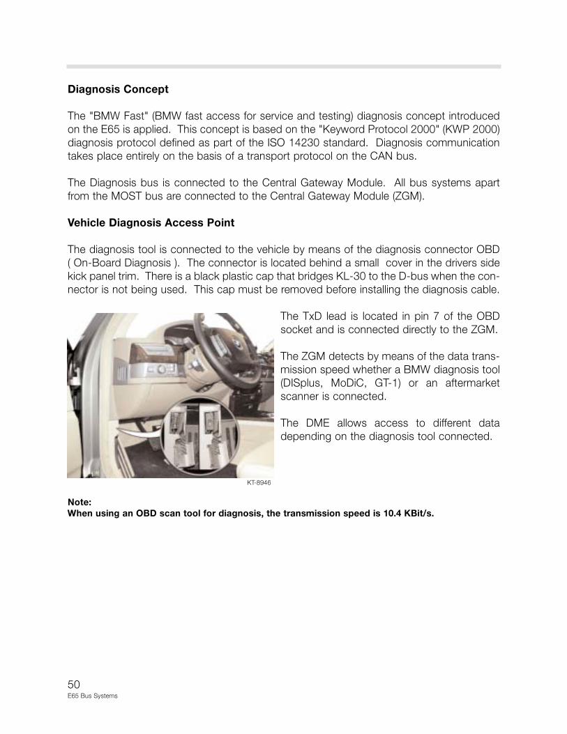
Vehicle Diagnosis Access Point
The diagnosis tool is connected to the vehicle by means of the diagnosis connector OBD
( On-Board Diagnosis ). The connector is located behind a small cover in the drivers side
kick panel trim. There is a black plastic cap that bridges KL-30 to the D-bus when the con-
nector is not being used. This cap must be removed before installing the diagnosis cable.
The TxD lead is located in pin 7 of the OBD
socket and is connected directly to the ZGM.
The ZGM detects by means of the data trans-
mission speed whether a BMW diagnosis tool
(DISplus, MoDiC, GT-1) or an aftermarket
scanner is connected.
The DME allows access to different data
depending on the diagnosis tool connected.
Note:
When using an OBD scan tool for diagnosis, the transmission speed is 10.4 KBit/s.
KT-8946

51E65 Bus Systems
Review Questions
1. How many bus systems is the E65 equipped with? Hint: Don’t forget the sub-busses.
2. Which modules perform the task of “Gateway”?
3. How many terminal resistors are located in the PT-CAN? Where are they located?
What should the total resistance be on the PT-CAN?
4. What are some of the handling precautions to be adhered to when working with fiber-
optic cables?
5. What is the difference between the fiber-optic connector of a MOST component and a
byteflight component?
6. What test is available in case of an interruption in the MOST circuit?
7. What is the difference between the D-Bus of the E65 and other BMW models?


![[Code List] E65/E66 Available Coding List Page 1 of 8morski-online.pl/ftp/e65-e66-available-coding-list.pdf · New Posts Private Messages FAQ ... englisch english [Code List] E65/E66](https://img.dokumen.tips/doc/110x75/5a856b6e7f8b9ac96a8c628f/code-list-e65e66-available-coding-list-page-1-of-8morski-posts-private-messages.jpg)