Embed Size (px)
Citation preview

TABLE OF CONTENTS
Safety Notices ...................................................................................................... 1
Introduction .......................................................................................................... 3System Overview............................................................................................................... 3
Installation ............................................................................................................ 5Console Mounting.............................................................................................................. 5Monitor and Power Connections........................................................................................ 5Console Main Harness ...................................................................................................... 6
System Operation ................................................................................................ 7Display Panel ..................................................................................................................... 7Power Sequence ............................................................................................................... 7Initial Startup...................................................................................................................... 7Display Intensity................................................................................................................. 8Modes ................................................................................................................................ 8
Monitor Mode .................................................................................................................................... 8Row Failure ....................................................................................................................................... 8
Alarm Mode ....................................................................................................................... 9Row Failure ....................................................................................................................................... 9
System Configuration........................................................................................ 11Threshold Settings........................................................................................................... 11
Seeding Rate Formulas ..................................................................................... 13Population in Seeds Per Acre ......................................................................................................... 13Seed Spacing.................................................................................................................................. 13
Troubleshooting................................................................................................. 15
PM100 Service Parts.......................................................................................... 17Monitor ............................................................................................................................. 17Planter Harnesses ........................................................................................................... 17Planter Y Cables.............................................................................................................. 17Planter Extensions........................................................................................................... 17
PM100E Service Parts ....................................................................................... 19Monitor ............................................................................................................................. 19PM100E Monitor .............................................................................................................. 19Planter Harnesses ........................................................................................................... 19
PM100/PM100E Planter Monitor11001-1426-200612
i

TABLE OF CONTENTS
PM100/PM100E Planter Monitor11001-1426-200612
ii

TABLE OF CONTENTS
Safety Notices ...................................................................................................... 1
Introduction .......................................................................................................... 3System Overview............................................................................................................... 3
Installation ............................................................................................................ 5Console Mounting.............................................................................................................. 5Monitor and Power Connections........................................................................................ 5Console Main Harness ...................................................................................................... 6
System Operation ................................................................................................ 7Display Panel ..................................................................................................................... 7Power Sequence ............................................................................................................... 7Initial Startup...................................................................................................................... 7Display Intensity................................................................................................................. 8Modes ................................................................................................................................ 8
Monitor Mode .................................................................................................................................... 8Row Failure ....................................................................................................................................... 8
Alarm Mode ....................................................................................................................... 9Row Failure ....................................................................................................................................... 9
System Configuration........................................................................................ 11Threshold Settings........................................................................................................... 11
Seeding Rate Formulas ..................................................................................... 13Population in Seeds Per Acre ......................................................................................................... 13Seed Spacing.................................................................................................................................. 13
Troubleshooting................................................................................................. 15
PM100 Service Parts.......................................................................................... 17Monitor ............................................................................................................................. 17Planter Harnesses ........................................................................................................... 17Planter Y Cables.............................................................................................................. 17Planter Extensions........................................................................................................... 17
PM100E Service Parts ....................................................................................... 19Monitor ............................................................................................................................. 19PM100E Monitor .............................................................................................................. 19Planter Harnesses ........................................................................................................... 19
PM100/PM100E Planter Monitor11001-1426-200612
i

TABLE OF CONTENTS
PM100/PM100E Planter Monitor11001-1426-200612
ii

OPERATOR’S MANUAL
SAFETY NOTICES
Safety notices are one of the primary ways to call attention to potential hazards.
This Safety Alert Symbol identifies important safety messages in this manual. When you see this symbol, carefully read the message that follows. Be alert to the possibility of personal injury or death.
Use of the word WARNING indicates a potentially hazardous situation which, if not avoided, could result in death or serious injury.
Use of the word CAUTION with the Safety Alert Symbol indicates a potentially hazardous situation which, if not avoided, may result in minor or moderate injury.
Use of the word CAUTION without the safety alert symbol indicates a potentially hazardous situation which, if not avoided, may result in equipment damage.
!
PM100/PM100E Planter Monitor11001-1426-200612
1

OPERATOR’S MANUAL
PM100/PM100E Planter Monitor11001-1426-200612
2 SAFETY NOTICES

OPERATOR’S MANUAL
INTRODUCTION
SYSTEM OVERVIEWThe PM100 and PM100E are seed flow monitoring systems that provide indicators for row failure and low seed flow.
Features include:
• Monitoring of 1-16 rows (PM100) and 1-8 rows (PM100E)• Automatic sensor detection• LED row indicators• Dual function row failure indication - allows all LED’s to blink while
planting and turn off to indicate row failure, or may be set to illuminate to indicate row failure
• Adjustable failure threshold settings• LED brightness adjustment
Figure 1PM100/PM100E Planter Monitor
PM100/PM100E Planter Monitor11001-1426-200612
INTRODUCTION 3

OPERATOR’S MANUAL
PM100/PM100E Planter Monitor11001-1426-200612
4 INTRODUCTION

OPERATOR’S MANUAL
INSTALLATION
CONSOLE MOUNTINGTo mount the PM100/PM100E console, use the mounting bracket as a template for drilling. Mount the console in a location that is easy to view and easy to reach for threshold adjustment and alarm silencing.
Figure 2Console Mounting
Before drilling, ensure that the power and main hitch harness can be routed in the proper manner. Harness retention and routing outside of the cab is also important.
Do not use the enclosure as a guide when drilling. This may cause damage to the mounting bracket.
MONITOR AND POWER CONNECTIONSRoute the monitor harness to the rear of the tractor where the planter harness can be conveniently connected.
Route the power leads of the main harness to the battery. Allow some slack to tie the harness off to the console bracket for strain relief and protection of the harness.
Connect black lead to negative (-) battery terminal and red lead to positive (+) terminal. Route battery leads away from alternator, battery cables, spark plugs and other magnetic field sources.
PM100/PM100E Planter Monitor11001-1426-200612
INSTALLATION 5

OPERATOR’S MANUAL
IMPORTANT: Be sure harnesses are not pinched, kinked or positioned against sharp edges and cannot be stepped on.
Figure 3Monitor And Power Connections
IMPORTANT: The seed monitor is designed to operate on 12 volts DC only. Always connect red lead to positive (+) battery terminal and black lead to negative (-) terminal regardless of whether tractor has a negative or positive ground system.
CONSOLE MAIN HARNESSInsert the connectors of the harness into the mating connectors located on the console bottom. Each connector is different and may only be inserted into its mate.
Figure 4Main Harness Connection
Route the main harness to the rear of the tractor. Mount the harness to a suitable location at the rear of the tractor assuring the connector will reach the implement connector at the hitch.
+ -
12 Vdc
Red Black
Power 12V - RedGround - Black
MainConsoleHarness
PM100/PM100E Planter Monitor11001-1426-200612
6 INSTALLATION

OPERATOR’S MANUAL
SYSTEM OPERATION
DISPLAY PANELThe monitor can be set in monitor mode or alarm mode. In monitor mode, the row indicator lamps will blink each time a seed is detected with a maximum of 20 seeds per second. In alarm mode, the row light will only illuminate when a row failure is detected.
Figure 5Display Panel
POWER SEQUENCEThe Power Switch has three positions:
• Down - move the switch down to turn off monitor power.• Center - move the switch to the center position to turn monitor power
on.• Up - push the switch up to the momentary position to silence the alarm
or to change the mode during power up.
The +/- switch is used to set the minimum seeding rate settings.
INITIAL STARTUPMove the I-O (power) switch to the center position to turn on the monitor. An indicator lamp in the right hand corner will illuminate while power is on.
At power up, the monitor does a display test by illuminating all row indicator lamps. The alarm will output a single chirp during the display test. The row indicator lamps will then be off until planting begins.
The monitor automatically detects which sensors are connected. If a sensor is disconnected, the row indicator lamp corresponding to that row will not illuminate.
To disable a row from being monitored, turn the monitor off by moving the power switch down. Unplug the sensor at the row unit. Turn the monitor back on and the row indicator lamp will be disabled.
Power/Alarm CancelSwitch
RowIndicators
Minimum seedingrate settings
PowerIndicatorLamp
PM100/PM100E Planter Monitor11001-1426-200612
SYSTEM OPERATION 7

OPERATOR’S MANUAL
Figure 6Power Up Indicator And Alarm Test
DISPLAY INTENSITYOnce the unit has completed the self test, the light intensity can be changed. Move the power switch up to the momentary position to change the light intensity. Keep repeating the procedure until a desired intensity is reached. The alarm will chirp for each step and provide a long chirp if a minimum or maximum setting is reached. Once the dimmest setting is reached, the indicator will reverse and start to brighten.
MODES
MONITOR MODEIn monitor mode, each time a seed is detected, the row indicator lamp will blink. The maximum blink rate is 20 times per second. Rows that are planting at a slower rate will appear to be less intense. Any row failure that is detected or seed application that falls below the established minimum threshold will be indicated by a row indicator lamp that is not illuminated.
To set in monitor mode, toggle the I-O (power) switch from On (I) to Off (O) and back to On (I). All row indicator lamps will illuminate for two seconds.
ROW FAILUREIn monitor mode, if an ALL ROWS FAILURE is detected, none of the row indicator lamps will illuminate and the alarm will chirp eight times then silence.
While planting, if one or more rows fail, the corresponding row(s) will darken and the alarm will sound. The alarm can be silenced by moving the I-O (power) switch up momentarily. The alarm will remain silenced until an ALL ROWS FAILURE condition occurs (typically at the end of a row), the row begins working again, or the monitor power is cycled.
Figure 7Example Of Row Failure - Monitor Mode
1 2 3 4 5 6 7 8 9 10 11 12 13 14 15 16
1 2 3 4 5 6 7 8 9 10 11 12 13 14 15 16
Row Failure
PM100/PM100E Planter Monitor11001-1426-200612
8 SYSTEM OPERATION
OPERATOR’S MANUAL
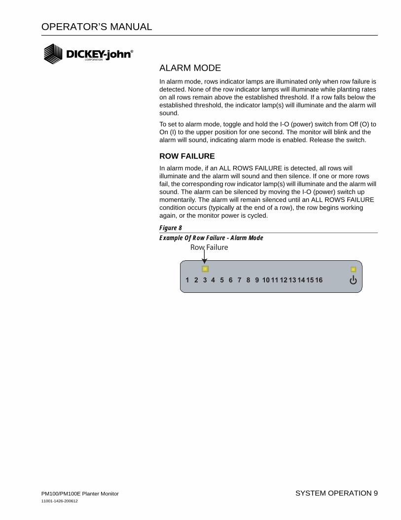
ALARM MODEIn alarm mode, rows indicator lamps are illuminated only when row failure is detected. None of the row indicator lamps will illuminate while planting rates on all rows remain above the established threshold. If a row falls below the established threshold, the indicator lamp(s) will illuminate and the alarm will sound.
To set to alarm mode, toggle and hold the I-O (power) switch from Off (O) to On (I) to the upper position for one second. The monitor will blink and the alarm will sound, indicating alarm mode is enabled. Release the switch.
ROW FAILUREIn alarm mode, if an ALL ROWS FAILURE is detected, all rows will illuminate and the alarm will sound and then silence. If one or more rows fail, the corresponding row indicator lamp(s) will illuminate and the alarm will sound. The alarm can be silenced by moving the I-O (power) switch up momentarily. The alarm will remain silenced until an ALL ROWS FAILURE condition occurs (typically at the end of a row), the row begins working again, or the monitor power is cycled.
Figure 8Example Of Row Failure - Alarm Mode
1 2 3 4 5 6 7 8 9 10 11 12 13 14 15 16
Row Failure
PM100/PM100E Planter Monitor11001-1426-200612
SYSTEM OPERATION 9

OPERATOR’S MANUAL
PM100/PM100E Planter Monitor11001-1426-200612
10 SYSTEM OPERATION
OPERATOR’S MANUAL
SYSTEM CONFIGURATION
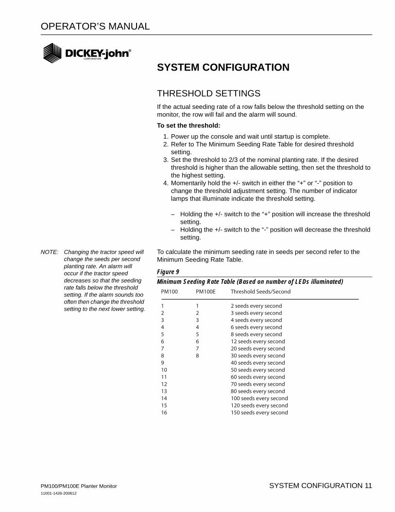
THRESHOLD SETTINGSIf the actual seeding rate of a row falls below the threshold setting on the monitor, the row will fail and the alarm will sound.
To set the threshold:1. Power up the console and wait until startup is complete.2. Refer to The Minimum Seeding Rate Table for desired threshold
setting.3. Set the threshold to 2/3 of the nominal planting rate. If the desired
threshold is higher than the allowable setting, then set the threshold to the highest setting.
4. Momentarily hold the +/- switch in either the “+” or “-” position to change the threshold adjustment setting. The number of indicator lamps that illuminate indicate the threshold setting.
– Holding the +/- switch to the “+” position will increase the threshold setting.
– Holding the +/- switch to the “-” position will decrease the threshold setting.
NOTE: Changing the tractor speed will change the seeds per second planting rate. An alarm will occur if the tractor speed decreases so that the seeding rate falls below the threshold setting. If the alarm sounds too often then change the threshold setting to the next lower setting.
To calculate the minimum seeding rate in seeds per second refer to the Minimum Seeding Rate Table.
Figure 9Minimum Seeding Rate Table (Based on number of LEDs illuminated)
PM100 PM100E Threshold Seeds/Second
1 1 2 seeds every second2 2 3 seeds every second3 3 4 seeds every second4 4 6 seeds every second5 5 8 seeds every second6 6 12 seeds every second7 7 20 seeds every second8 8 30 seeds every second9 40 seeds every second10 50 seeds every second11 60 seeds every second12 70 seeds every second13 80 seeds every second14 100 seeds every second15 120 seeds every second16 150 seeds every second
PM100/PM100E Planter Monitor11001-1426-200612
SYSTEM CONFIGURATION 11

OPERATOR’S MANUAL
PM100/PM100E Planter Monitor11001-1426-200612
12 SYSTEM CONFIGURATION
OPERATOR’S MANUAL
SEEDING RATE FORMULAS
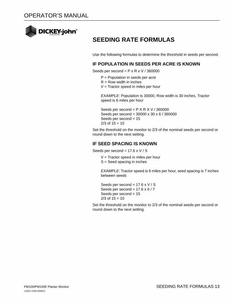
Use the following formulas to determine the threshold in seeds per second.
IF POPULATION IN SEEDS PER ACRE IS KNOWNSeeds per second = P x R x V / 360000
P = Population in seeds per acreR = Row width in inchesV = Tractor speed in miles per hour
EXAMPLE: Population is 30000, Row width is 30 inches, Tractor speed is 6 miles per hour
Seeds per second = P X R X V / 360000Seeds per second = 30000 x 30 x 6 / 360000Seeds per second = 152/3 of 15 = 10
Set the threshold on the monitor to 2/3 of the nominal seeds per second or round down to the next setting.
IF SEED SPACING IS KNOWNSeeds per second = 17.6 x V / S
V = Tractor speed in miles per hourS = Seed spacing in inches
EXAMPLE: Tractor speed is 6 miles per hour, seed spacing is 7 inches between seeds
Seeds per second = 17.6 x V / SSeeds per second = 17.6 x 6 / 7Seeds per second = 152/3 of 15 = 10
Set the threshold on the monitor to 2/3 of the nominal seeds per second or round down to the next setting.
PM100/PM100E Planter Monitor11001-1426-200612
SEEDING RATE FORMULAS 13

OPERATOR’S MANUAL
PM100/PM100E Planter Monitor11001-1426-200612
14 SEEDING RATE FORMULAS

OPERATOR’S MANUAL
TROUBLESHOOTING
NOTE: Do not replace fuse with one having a higher amperage rating, the console could be damaged internally.
PROBLEM PROBABLE CAUSE CORRECTIVE ACTION
Unit will not power on. No LEDs will illuminate during the power up sequence.
Loose connection between power harness and monitor.
Make sure harness connection is centered and fully inserted. Make sure the power harness is properly connected to the monitor.
Bad fuse. Check the fuse in the power harness near the battery. If bad, replace with a 3A AGC fuse. Make sure the positive and negative connections of the power harness are not reversed.
Defective power harness or monitor.
If the fuse is bad again, the power harness or the console can be faulty and require replacement. Contact your distributor or DICKEY-john Service Department at 1-800-637-3302.
Bad battery connection. Check battery connections and make sure the connections are clean and tight.
Low system voltage. Make sure battery voltage is between 10 and 16 volts DC.
PM100/PM100E Planter Monitor11001-1426-200612
TROUBLESHOOTING 15
OPERATOR’S MANUAL
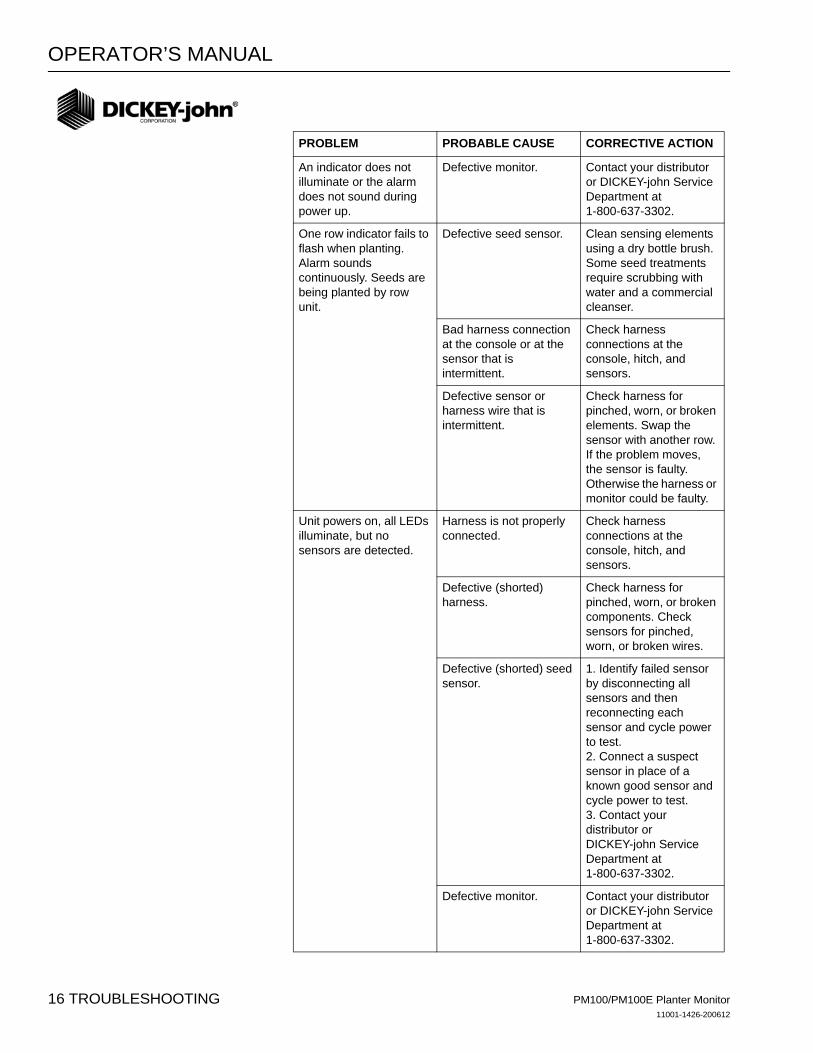
PROBLEM PROBABLE CAUSE CORRECTIVE ACTION
An indicator does not illuminate or the alarm does not sound during power up.
Defective monitor. Contact your distributor or DICKEY-john Service Department at 1-800-637-3302.
One row indicator fails to flash when planting. Alarm sounds continuously. Seeds are being planted by row unit.
Defective seed sensor. Clean sensing elements using a dry bottle brush. Some seed treatments require scrubbing with water and a commercial cleanser.
Bad harness connection at the console or at the sensor that is intermittent.
Check harness connections at the console, hitch, and sensors.
Defective sensor or harness wire that is intermittent.
Check harness for pinched, worn, or broken elements. Swap the sensor with another row. If the problem moves, the sensor is faulty. Otherwise the harness or monitor could be faulty.
Unit powers on, all LEDs illuminate, but no sensors are detected.
Harness is not properly connected.
Check harness connections at the console, hitch, and sensors.
Defective (shorted) harness.
Check harness for pinched, worn, or broken components. Check sensors for pinched, worn, or broken wires.
Defective (shorted) seed sensor.
1. Identify failed sensor by disconnecting all sensors and then reconnecting each sensor and cycle power to test. 2. Connect a suspect sensor in place of a known good sensor and cycle power to test.3. Contact your distributor or DICKEY-john Service Department at 1-800-637-3302.
Defective monitor. Contact your distributor or DICKEY-john Service Department at 1-800-637-3302.
PM100/PM100E Planter Monitor11001-1426-200612
16 TROUBLESHOOTING

OPERATOR’S MANUAL
PM100 SERVICE PARTS
MONITORPM100 Monitor 46794-0111
Mounting bracket 46794-0080
Fuse, AGC 3A 20112-0049
Power harness 46794-0530
16 row cab harness 46794-0510
PLANTER HARNESSESStandard, 4 row 45841-0530
Standard, 6 row 45841-0550
Standard, 8 row 45841-0570
Standard, 12 row 45841-0590
Standard, 16 row 45841-1080
PLANTER Y CABLESY-Cable, 8 row squadron 45968-0610
Y-Cable, 12 row squadron 45968-0960
Y-Cable, 16 row squadron 45968-0950
PLANTER EXTENSIONSExtension cable, hitch, 6’ 45841-0810
Extension cable, hitch, 15’ 45968-0320
Extension cable, hitch, 30’ 45968-0321
PM100/PM100E Planter Monitor11001-1426-200612
PM100 SERVICE PARTS 17

OPERATOR’S MANUAL
PM100/PM100E Planter Monitor11001-1426-200612
18 PM100 SERVICE PARTS

OPERATOR’S MANUAL
PM100E SERVICE PARTS
MONITOR
PM100E Monitor 46794-0110
Mounting bracket 46794-0800
Fuse, AGC 3A 20112-0049
Power harness 46794-0530
8 row cab harness, 10 pin Metri-Pack 46794-0520
8 row cab harness, 37 pin AMP CPC 46794-0500
PLANTER HARNESSES 37 Pin AMP CPC 10 Pin Metri-Pak
4 row harness 45841-0530 46794-0540
6 row harness 45841-0550 46794-0550
8 row harness 45841-0570 46794-0560
EXTENSION HARNESSES45841-0810 (6 Ft)
46794-0570 (2m)
PM100/PM100E Planter Monitor11001-1426-200612
PM100E SERVICE PARTS 19

OPERATOR’S MANUAL
PM100/PM100E Planter Monitor11001-1426-200612
20 PM100E SERVICE PARTS

For DICKEY-john Service Department,call 1-800-637-3302 in either the U.S.A. or Canada
Headquarters:5200 Dickey-john Road, Auburn, IL 62615TEL: 217-438-3371, FAX: 217-438-6012, WEB: www.dickey-john.comEurope:DICKEY-john Europe S.A., 165, boulevard de Valmy, 92706 - Columbes - FranceTEL: 33 (0) 1 41 19 21 80, FAX: 33 (0) 1 47 86 00 07
Dealers have the responsibility of calling to the attention of their customers the following warranty prior to acceptance of an order from their customer for any DICKEY-john product.
DICKEY-john® WARRANTYDICKEY-john warrants to the original purchaser for use that, if any part of the product
proves to be defective in material or workmanship within one year from date of originalinstallation, and is returned to DICKEY-john within 30 days after such defect is discovered,DICKEY-john will (at our option) either replace or repair said part. This warranty does notapply to damage resulting from misuse, neglect, accident, or improper installation ormaintenance. Said part will not be considered defective if it substantially fulfills theperformance expectations. THE FOREGOING WARRANTY IS EXCLUSIVE AND INLIEU OF ALL OTHER WARRANTIES OF MERCHANTABILITY, FITNESS FORPURPOSE, AND OF ANY OTHER TYPE, WHETHER EXPRESS OR IMPLIED.DICKEY-john neither assumes nor authorizes anyone to assume for it any other obligation orliability in connection with said part and will not be liable for consequential damages.Purchaser accepts these terms and warranty limitations unless the product is returned withinfifteen days for full refund of purchase price.
Copyright 2006 DICKEY-john CorporationSpecifications subject to change without notice