Embed Size (px)
Citation preview

IOWA DOT ~ OFFICE OF BRIDGES AND STRUCTURES ~ LRFD BRIDGE DESIGN MANUAL ~ 5.2: 1
July 2018
TABLE OF CONTENTS ~ DECKS
5.2 Decks 5.2.1 General
5.2.1.1 Policy overview 5.2.1.2 Design information 5.2.1.3 Definitions 5.2.1.4 Abbreviations and notation 5.2.1.5 References
5.2.2 Loads 5.2.2.1 Dead 5.2.2.2 Live 5.2.2.3 Dynamic load allowance 5.2.2.4 Railing 5.2.2.5 Earthquake 5.2.2.6 Construction
5.2.3 Load application 5.2.3.1 Load modifier 5.2.3.2 Limit states
5.2.4 Deck analysis, design, and detailing 5.2.4.1 Traditional decks
5.2.4.1.1 Analysis and design 5.2.4.1.1.1 Analysis assumptions 5.2.4.1.1.2 Materials 5.2.4.1.1.3 Load and resistance factors 5.2.4.1.1.4 Section properties 5.2.4.1.1.5 Moment 5.2.4.1.1.6 Shear 5.2.4.1.1.7 Fatigue 5.2.4.1.1.8 Additional considerations
5.2.4.1.2 Detailing 5.2.4.2 Empirical decks 5.2.4.3 Prestressed deck panels
5.2.4.3.1 Analysis and design 5.2.4.3.1.1 Design criteria 5.2.4.3.1.2 Materials 5.2.4.3.1.3 Additional considerations
5.2.4.3.2 Detailing 5.2.4.4 Two-course decks
5.2.4.4.1 Analysis and design 5.2.4.4.2 Detailing
5.2 Decks
This article covers bridge decks designed by the AASHTO LRFD Specifications, Fourth Edition. The article replaces the previous Decks article that was based on the AASHTO Standard Specifications.
5.2.1 General
With minor modifications, the design procedures described in this article meet AASHTO LRFD Specifications, Fourth Edition [AASHTO-LRFD Section 9 and Section 13 Appendix A]. In addition to the AASHTO sections listed above, the designer should review related articles in this manual for haunches [BDM 5.3], pretensioned prestressed concrete beams (PPCB) [BDM 5.4], continuous welded plate girders

IOWA DOT ~ OFFICE OF BRIDGES AND STRUCTURES ~ LRFD BRIDGE DESIGN MANUAL ~ 5.2: 2
July 2018
(CWPG) [BDM 5.5], railings [5.8.1], sidewalks [5.8.2], expansion joints [BDM 5.8.3], and deck drains [BDM 5.8.4].
5.2.1.1 Policy overview [AASHTO-LRFD 4.6.2.1, 9.7.1.1, 9.7.3, 13.7.3.1.2]
For typical pretensioned prestressed concrete beam (PPCB), continuous welded plate girder (CWPG), and rolled steel beam (RSB) bridges the office requires traditional, single course cast-in-place reinforced concrete decks. Decks shown on the recently revised standard sheets [OBS SS 4305-4310, 4380-4385, 4556-4561] were designed by the LRFD strip method [AASHTO-LRFD 4.6.2.1, 9.7.3] and, for all non-standard deck designs, the office requires design by the LRFD strip method. The traditional deck is placed as a single, cast-in-place concrete course 8 inches thick, which exceeds the minimum thickness required by the AASHTO LRFD Specifications [AASHTO-LRFD 9.7.1.1]. The deck has two transverse and two longitudinal layers of reinforcing. During construction the bottom transverse layer is placed first, then the bottom longitudinal layer, then the top longitudinal layer, and finally the top transverse layer. Each edge of the deck has a moderate overhang for 18 to 24 inches of roadway surface plus an F-shape barrier rail. The top one-half inch of the deck is considered a non-structural built-in wearing surface (BWS) that is longitudinally grooved for texture and pavement markings. The weight for a 0.020 ksf future wearing surface (FWS) is included in the design. The overhang for a typical deck, measured from center of exterior beam or girder to edge of deck, is 37 inches for CWPG bridges, 37 inches for A-D PPCB bridges, and 42 inches for BTB-BTE PPCB bridges. Thickness of the overhang tapers from a permissible range of 9.00 to 10.25 inches at the beam or girder flange to 8.75 inches at edge of deck. These thicknesses exceed the minimum required by the AASHTO specifications [AASHTO-LRFD 13.7.3.1.2]. The designer need not check overhangs with the TL-4, F-shape barrier rail shown on standard cross sections. The bottom of the typical deck is formed with removable formwork between haunches above the beams or girders. For a deck without superelevation, the top of the deck has a central parabolic crown and a 2.0% transverse slope on each side of the crown. Seat elevations for the constant-height beams or girders are varied in the design to create the overall crown in the deck. For the builder’s use during construction, the office requires the designer to provide top of deck elevations above each beam or girder at constant 8 to 10 feet intervals on each span. In order to minimize deck cracking, the standard specifications require Class C concrete with limited fly ash and ground granulated blast furnace slag substitutions [IDOT SS 2412.02]. In some cases, the office specifies either high performance concrete (HPC) or improved durability concrete (IDC) instead of Class C concrete. The HPC or IDC requires a developmental specification developed by the Office of Materials. HPC is available for the regions shown in Figure 5.2.4.1.1.2. All reinforcing in the deck is required to be epoxy coated, except all barrier rail to bridge deck/wing reinforcement for interstate and primary bridges shall be stainless steel. Alternate corrosion protection for reinforcement requires the approval of the supervising Section Leader. Above piers, decks are reinforced for longitudinal negative moment differently depending on the type of superstructure. For pretensioned prestressed concrete beam (PPCB) bridges, extra negative moment bars of specified length are added between the continuous longitudinal top bars. Deck standard sheets have the correct negative moment reinforcing for the span lengths available with standard PPCBs. For typical bridges that make use of the deck standard sheets the designer need not check deck reinforcement, but for greater spans or wider, nonstandard beam spacings the designer shall check the need for additional deck reinforcement and add reinforcement as necessary. For continuous welded plate girder (CWPG) bridges, the office meets the minimum quantity of negative moment reinforcement required by the AASHTO LRFD Specifications with an amount of longitudinal reinforcing that is continuous over the entire bridge length.

IOWA DOT ~ OFFICE OF BRIDGES AND STRUCTURES ~ LRFD BRIDGE DESIGN MANUAL ~ 5.2: 3
July 2018
For skews of 7.5 degrees or less the transverse reinforcement is placed parallel with the skew. For larger skews the transverse deck reinforcement is placed perpendicular to the longitudinal axis of the bridge. Transverse reinforcement is placed radially for curved bridges. The office permits the use of stay-in-place, prestressed concrete deck panels for PPCB bridges on rural highways with limited average daily traffic counts. The panels are designed to eliminate formwork and to support deck concrete before it cures. In the completed bridge the panels are composite with the cast-in-place deck. For all typical PPCB and CWPG bridges the office requires the designer to specify permissible transverse construction joints and a deck placing sequence. For all except single-span and two-span CWPG bridges, the contractor has the option of submitting alternate procedures for placing the deck concrete. In most cases the contractor is given approval to place the deck continuously starting at one end. The designer should provide a permissible longitudinal construction joint whenever the out-to-out deck width exceeds 80 feet for constant and tapered width bridges. Otherwise longitudinal construction joints are not required except for staged construction. When a staged longitudinal construction joint is used and the construction takes more than one season, exposed transverse steel reinforcing shall be stainless steel. The exposed transverse stainless steel reinforcing shall generally be lapped with transverse epoxy coated steel reinforcing on each side of the staged longitudinal construction joint. Longitudinal median joints with a 2-inch gap may be specified when the out-to-out bridge deck width for a single bridge would exceed 120 feet. A longitudinal median joint effectively divides the bridge superstructure into two separate bridges. In most cases, the joint is placed between the backs of two barrier rails which separate head-to-head traffic lanes [BDM 3.2.6.2.1]. Slotted drains may also be incorporated at the joint. In special cases approved by the Chief Structural Engineer or Assistant Bridge Engineer the office permits use of a two-course deck. Guidelines for design and detailing of the deck are given in another article [BDM 5.2.4.4]. The designer shall include a bridge deck dimensions table on the notes and quantities sheet of each set of bridge plans [CADD Notes E110 and M110, BDM 13.3.2]. The table is intended to provide consistent information for analyzing costs.
5.2.1.2 Design information
For typical roadway widths the office provides standard sheets that detail shape, cover, and reinforcement for decks on PPCB and CWPG bridges [OBS SS 4305-4310, 4380-4385, 4556-4561]. The office also provides bar lists that include deck reinforcement for PPCB bridges with integral abutments [OBS SS 4514-4521].
5.2.1.3 Definitions
Longitudinal is the direction associated with the roadway centerline of construction and main girders. Section Leader is the supervisor of the Office of Bridges and Structures preliminary bridge section, final design section, or consultant coordination section. Transverse is the direction normal to the roadway centerline of construction and main girders.
5.2.1.4 Abbreviations and notation [AASHTO-LRFD 3.3.2, 3.10.4.2]
ADT, average daily traffic BWS, built-in wearing surface CWPG, continuous welded plate girder d, depth of the deck from compression surface to centroid of tension reinforcing bar
IOWA DOT ~ OFFICE OF BRIDGES AND STRUCTURES ~ LRFD BRIDGE DESIGN MANUAL ~ 5.2: 4
July 2018
DC, dead load of deck, sidewalk, railings, and nonstructural attachments other than utilities [AASHTO-LRFD 3.3.2] DW, dead load of future wearing surface and any utilities attached directly to the deck [AASHTO-LRFD 3.3.2] f’c, specified 28-day concrete compressive strength FWS, future wearing surface GUTS, guaranteed ultimate tensile strength HPC, high performance concrete IDC, improved durability concrete LRFD, load and resistance factor design PPCB, pretensioned prestressed concrete beam RSB, rolled steel beam SD1, horizontal response spectral acceleration coefficient at 1.0-sec. period modified by long-period site factor [AASHTO-LRFD 3.10.4.2] VPD, vehicles per day
5.2.1.5 References
Hartle, R.A., K.E. Wilson, W.A. Amrhein, S.D. Zang, J.W. Bouscher, and L.E. Volle. LRFD Design Example for Steel Girder Superstructure Bridge with Commentary. Moon Township: Michael Baker Jr., Inc., November 2003. Modjeski and Masters, Inc. “Lecture 11, Decks and Lecture 17, Overview of Railings, Joints and Bearings.” FHWA Training Course, LRFD Design of Highway Bridges. Harrisburg: Modjeski and Masters, Inc., December 1994. Office of Construction. Construction Manual. Ames: Office of Construction, Iowa Department of Transportation, 2006. (Available on the Internet at: http://www.iowadot.gov/erl/current/CM/Navigation/nav.pdf) Precast/Prestressed Concrete Institute (PCI). Bridge Design Manual. Chicago: PCI, 1997 with revisions to 2003. Wassef, W.G., C. Smith, C.M. Clancy, and M.J. Smith. Comprehensive Design Example for Prestressed Concrete (PSC) Girder Superstructure Bridge with Commentary. Harrisburg: Modjeski and Masters, Inc., November 2003.
5.2.2 Loads
5.2.2.1 Dead [AASHTO-LRFD 3.3.2]
For the design of a traditional deck the office does not make a distinction between dead load applied before or after curing of the deck because the future wearing surface is assumed not to act compositely with the deck. All dead load is applied with respect to the same deck cross section for the same span and continuity conditions. However, because of difference in load factor the designer does need to make a distinction between DC, dead load of structural components and nonstructural attachments, and DW, dead load of wearing surfaces and utilities [AASHTO-LRFD 3.3.2]. For two course decks the designer shall consider the second course as DC load because it will be placed under relatively controlled conditions by the bridge contractor. The transverse strip used in design that spans between beams or girders shall be designed to carry the weight of the deck strip, the future wearing surface of 0.020 ksf on the strip, sidewalks, medians, and any additional dead loads. The transverse strip on the overhang additionally shall be designed for the weight of the barrier rail and other dead loads such as sidewalks or light poles along the edge of the deck. For staged construction the designer shall consider the load of the temporary barrier rail.
IOWA DOT ~ OFFICE OF BRIDGES AND STRUCTURES ~ LRFD BRIDGE DESIGN MANUAL ~ 5.2: 5
July 2018
5.2.2.2 Live [AASHTO-LRFD 3.6.1, 3.6.1.3.4, 4.6.2.1, Table A4-1]
For a typical deck the designer shall use the transverse deck strips defined in the AASHTO LRFD specifications [AASHTO-LRFD 4.6.2.1]. The strips shall be designed for HL-93 live load (LL) [AASHTO-LRFD 3.6.1]. Where applicable the designer may use the tabulated live load moments [AASHTO-LRFD Table A4-1]. When the overhang length exceeds the office’s preferred maximum of about 3.50 feet the designer will need to consider wheel loads on the overhang. The designer shall not use the optional uniformly distributed live load of 1.0 k/ft [AASHTO LRFD 3.6.1.3.4]. Overhang lengths greater than the preferred maximum shall be approved by the supervising Section Leader.
5.2.2.3 Dynamic load allowance [AASHTO-LRFD 3.6.2]
The dynamic load allowance (IM) shall be taken from the AASHTO LRFD Specifications [AASHTO-LRFD 3.6.2].
5.2.2.4 Railing [AASHTO-LRFD A13]
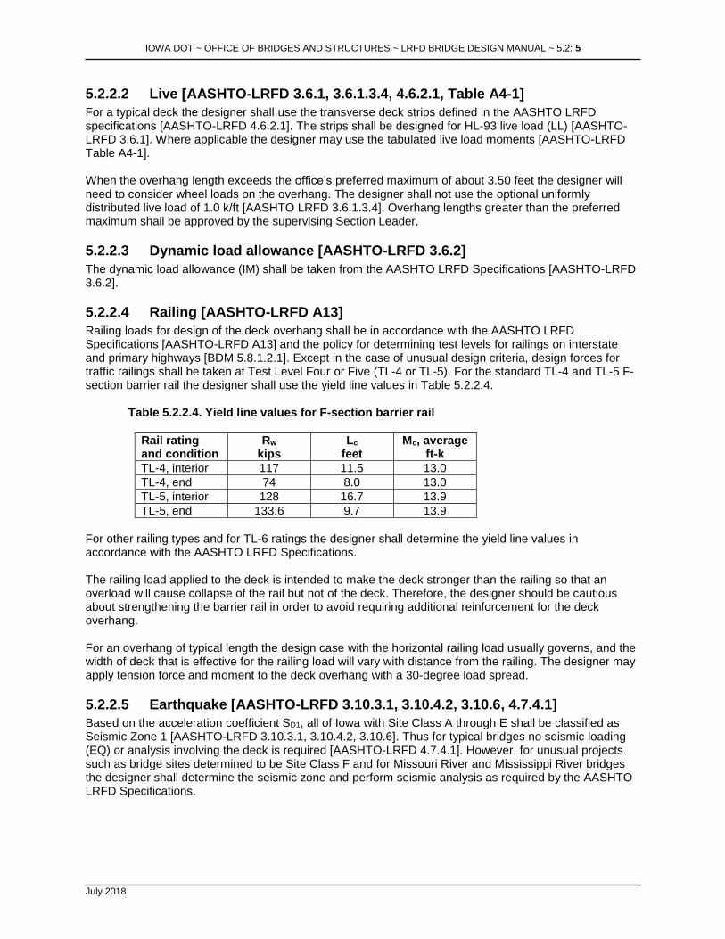
Railing loads for design of the deck overhang shall be in accordance with the AASHTO LRFD Specifications [AASHTO-LRFD A13] and the policy for determining test levels for railings on interstate and primary highways [BDM 5.8.1.2.1]. Except in the case of unusual design criteria, design forces for traffic railings shall be taken at Test Level Four or Five (TL-4 or TL-5). For the standard TL-4 and TL-5 F-section barrier rail the designer shall use the yield line values in Table 5.2.2.4.
Table 5.2.2.4. Yield line values for F-section barrier rail
Rail rating and condition
Rw
kips Lc
feet Mc, average
ft-k
TL-4, interior 117 11.5 13.0
TL-4, end 74 8.0 13.0
TL-5, interior 128 16.7 13.9
TL-5, end 133.6 9.7 13.9
For other railing types and for TL-6 ratings the designer shall determine the yield line values in accordance with the AASHTO LRFD Specifications. The railing load applied to the deck is intended to make the deck stronger than the railing so that an overload will cause collapse of the rail but not of the deck. Therefore, the designer should be cautious about strengthening the barrier rail in order to avoid requiring additional reinforcement for the deck overhang. For an overhang of typical length the design case with the horizontal railing load usually governs, and the width of deck that is effective for the railing load will vary with distance from the railing. The designer may apply tension force and moment to the deck overhang with a 30-degree load spread.
5.2.2.5 Earthquake [AASHTO-LRFD 3.10.3.1, 3.10.4.2, 3.10.6, 4.7.4.1]
Based on the acceleration coefficient SD1, all of Iowa with Site Class A through E shall be classified as Seismic Zone 1 [AASHTO-LRFD 3.10.3.1, 3.10.4.2, 3.10.6]. Thus for typical bridges no seismic loading (EQ) or analysis involving the deck is required [AASHTO-LRFD 4.7.4.1]. However, for unusual projects such as bridge sites determined to be Site Class F and for Missouri River and Mississippi River bridges the designer shall determine the seismic zone and perform seismic analysis as required by the AASHTO LRFD Specifications.
IOWA DOT ~ OFFICE OF BRIDGES AND STRUCTURES ~ LRFD BRIDGE DESIGN MANUAL ~ 5.2: 6
July 2018
5.2.2.6 Construction
For most bridge projects it is assumed that construction can take place without cranes, construction vehicles, construction equipment, and concentrated quantities of construction materials on the deck. If, however, the contractor does need to place loads on the deck larger than those permitted by the Standard Specifications [IDOT SS 1105.12, D], the contractor will be required to submit structural analysis by an Iowa-licensed engineer for approval. Thus the bridge designer may be required to review construction loading after letting of the bridge contract.
5.2.3 Load application
5.2.3.1 Load modifier [AASHTO-LRFD 1.3.2, 3.4.1]
Load factors shall be adjusted by the load modifier, which accounts for ductility, redundancy, and operational importance [AASHTO-LRFD 1.3.2, 3.4.1]. For typical decks the load modifier shall be taken as 1.0.
5.2.3.2 Limit states [AASHTO-LRFD 5.6.7, A13.4]
For the typical PPCB, CWPG, or RSB reinforced concrete bridge deck, the designer shall consider the Strength I limit state for the portion of the deck spanning between beams or girders. Other limit states may apply in the unusual case when the deck is specially designed to function as a horizontal stiffening component in the completed bridge structure. For the deck overhang the designer shall consider the three design cases defined in the AASHTO LRFD Specifications [AASHTO-LRFD A13.4]. Because the crack control rules in the 2005 Interim [AASHTO-LRFD 5.7.3.4; AASHTO-LRFD 5.6.7 beginning with the 2017 8th Edition] are more stringent for decks than previous rules and because the previous Z-check rules have resulted in good deck performance, the office requires that the designer meet the Z-check rules in the AASHTO LRFD Specifications prior to 2005.
5.2.4 Deck analysis, design, and detailing
5.2.4.1 Traditional decks
This series of articles covers the design of the traditional, single course cast-in-place reinforced concrete deck used on most PPCB, CWPG, and RSB bridges.
5.2.4.1.1 Analysis and design [AASHTO-LRFD 4.6.2.1, Table A4-1, 5.6.3, 9.7.3, A13.4]
The load and resistance factor design method shall be used for the deck spanning between beams or girders and for the deck overhang. For design of typical decks the designer shall use the strip method [AASHTO-LRFD 4.6.2.1, Table A4-1, 9.7.3, 5.6.3] between beams and girders and Design Cases 1 through 3 for the overhang [AASHTO-LRFD A13.4]. The office prefers that the deck overhang length be a maximum of about 3.50 feet.
5.2.4.1.1.1 Analysis assumptions
For design by the equivalent strip method, the transverse strip shall be considered a continuous member supported at each beam or girder. In the case of staged construction or other conditions that require a closure pour or longitudinal construction joint the designer shall consider the deck span conditions at the various stages of deck placement.
5.2.4.1.1.2 Materials
IOWA DOT ~ OFFICE OF BRIDGES AND STRUCTURES ~ LRFD BRIDGE DESIGN MANUAL ~ 5.2: 7
July 2018
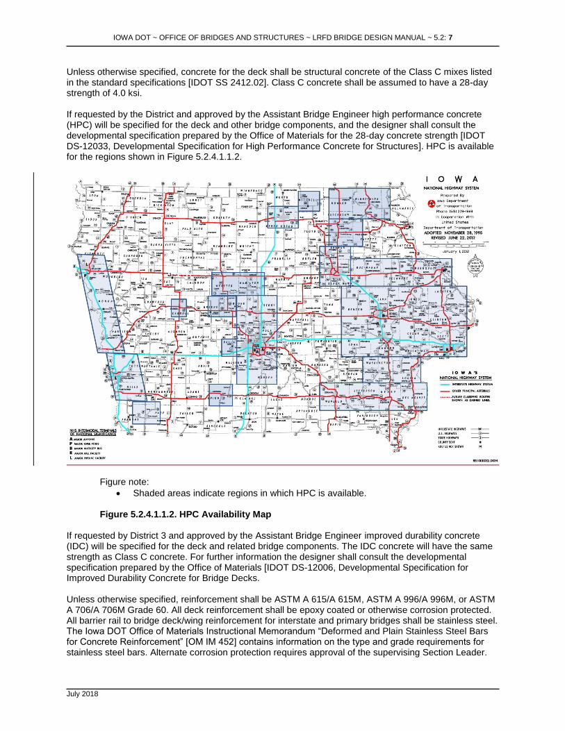
Unless otherwise specified, concrete for the deck shall be structural concrete of the Class C mixes listed in the standard specifications [IDOT SS 2412.02]. Class C concrete shall be assumed to have a 28-day strength of 4.0 ksi. If requested by the District and approved by the Assistant Bridge Engineer high performance concrete (HPC) will be specified for the deck and other bridge components, and the designer shall consult the developmental specification prepared by the Office of Materials for the 28-day concrete strength [IDOT DS-12033, Developmental Specification for High Performance Concrete for Structures]. HPC is available for the regions shown in Figure 5.2.4.1.1.2.
Figure note:
• Shaded areas indicate regions in which HPC is available.
Figure 5.2.4.1.1.2. HPC Availability Map If requested by District 3 and approved by the Assistant Bridge Engineer improved durability concrete (IDC) will be specified for the deck and related bridge components. The IDC concrete will have the same strength as Class C concrete. For further information the designer shall consult the developmental specification prepared by the Office of Materials [IDOT DS-12006, Developmental Specification for Improved Durability Concrete for Bridge Decks. Unless otherwise specified, reinforcement shall be ASTM A 615/A 615M, ASTM A 996/A 996M, or ASTM A 706/A 706M Grade 60. All deck reinforcement shall be epoxy coated or otherwise corrosion protected. All barrier rail to bridge deck/wing reinforcement for interstate and primary bridges shall be stainless steel. The Iowa DOT Office of Materials Instructional Memorandum “Deformed and Plain Stainless Steel Bars for Concrete Reinforcement” [OM IM 452] contains information on the type and grade requirements for stainless steel bars. Alternate corrosion protection requires approval of the supervising Section Leader.
IOWA DOT ~ OFFICE OF BRIDGES AND STRUCTURES ~ LRFD BRIDGE DESIGN MANUAL ~ 5.2: 8
July 2018
5.2.4.1.1.3 Load and resistance factors [AASHTO-LRFD 3.4.1, 5.5.4.2]
Load and resistance factors for the deck shall be taken from the AASHTO LRFD Specifications [AASHTO-LRFD 3.4.1, 5.5.4.2].
5.2.4.1.1.4 Section properties
For computation of all structural properties the uppermost one-half inch built-in wearing surface (BWS) shall be neglected. For the transverse spans between beams or girders the designer shall assume the deck to be singly reinforced. Compression reinforcement shall be neglected. For design of the deck overhang for horizontal railing loads, the designer shall consider both top and bottom reinforcement.
5.2.4.1.1.5 Moment [AASHTO-LRFD Table A4-1, 5.6.3]
Dead load moments for the transverse design strip shall be determined by elastic analysis of the strip for the applicable span and support conditions. If the deck span and superstructure configuration meet the assumptions of the tabulated live load moments in the AASHTO LRFD Specifications the designer may use the moments for the deck strip between beams or girders [AASHTO-LRFD Table A4-1]. Live load moments for the overhang need to be computed directly from structural principles. The designer shall meet LRFD flexural design requirements [AASHTO-LRFD 5.6.3].
5.2.4.1.1.6 Shear [AASHTO-LRFD 9.7.1.5]
For nonstandard designs the designer shall investigate punching shear effects at the outside toe of a barrier railing or railing post [AASHTO-LRFD 9.7.1.5].
5.2.4.1.1.7 Fatigue [AASHTO-LRFD 9.5.3]
For the typical reinforced concrete deck the designer need not investigate fatigue [AASHTO-LRFD 9.5.3]. The longitudinal reinforcing steel above piers typically will not require a fatigue check for bridges with a traditional deck. PPCB bridges are designed for simple span conditions with addition of the reinforcing above piers primarily to control cracking [BDM Table 5.4.1.4.1.1]. For CWPG bridges, the deck in a negative moment region at a pier is not considered part of the structural cross section, and thus the longitudinal reinforcing need not be designed for fatigue [BDM Table 5.5.2.4.1.4].
5.2.4.1.1.8 Additional considerations [AASHTO-LRFD 5.10.6, 9.7.3.2]
For a typical deck the transverse top and bottom reinforcement should be the same and should be selected for the greatest of the design moments between beams or girders. For the additional strength required by railing loads applied to the deck overhang, short 5j1 bars shall be added between the transverse, continuous top bars [OBS SS 4305-4385]. To avoid reinforcing congestion, the j-bars shall be limited to the #6 size. In all cases the reinforcing shall meet the requirements for shrinkage and temperature [AASHTO-LRFD 5.10.6] For a typical deck in the longitudinal direction, the bottom reinforcement shall be designed to meet the greater of the requirements for distribution [AASHTO-LRFD 9.7.3.2], crack control based on computed service load stress at the severe exposure condition [AASHTO-LRFD pre-2005 5.7.3.4], and shrinkage and temperature. Typically the top longitudinal reinforcement should be the same bar size and spacing as the bottom reinforcement but arranged so that the top bars are staggered with respect to the bottom bars. The longitudinal reinforcement also needs to be designed with respect to negative moment in beams or girders as indicated below.

IOWA DOT ~ OFFICE OF BRIDGES AND STRUCTURES ~ LRFD BRIDGE DESIGN MANUAL ~ 5.2: 9
July 2018
As shown on standard sheets for PPCB bridge decks [OBS SS 4380-4385, 4556-4561], additional longitudinal b2 bars of specified length are added between continuous b1 bars in order to control cracking caused by negative moments above the piers. The deck standard sheets have the correct negative moment reinforcing for the span lengths available with standard PPCBs. For typical bridges that make use of the deck standard sheets the designer need not check deck reinforcement, but for greater spans or wider, nonstandard beam spacings the designer shall check the need for additional deck reinforcement and add reinforcement as necessary. The additional bars should be designed using the appropriate AASHTO design method [BDM 5.4.1.4.1.7]. For CWPG bridge decks the AASHTO LRFD Specifications require minimum longitudinal reinforcement in negative moment regions, and the office follows the requirement but not the top to bottom proportion [BDM 5.5.2.4.1.5]. The b1 bars determined for negative moment regions, for distribution, and for shrinkage and temperature are continuous throughout the bridge deck, without change from negative to positive moment regions [OBS SS 4305-4310].
5.2.4.1.2 Detailing
For standard roadways without superelevation the profile of the top of the deck shall be as shown on standard sheets [OBS SS 4305-4385]. The typical profile consists of a central parabolic crown and side tangent slopes of 2.0%. The profile of the bottom of the deck consists of straight lines between the haunches above each set of two beams or girders. To aid the contractor in setting the top of deck elevations, the elevations shall be shown on the plans at intervals of 8 to 10 feet along each span. For decks on PPCBs, intervals shall be set with an even number of spaces between abutment and pier bearings and between pier bearings so there will be elevations at the centerlines of all spans and at all bearings. For decks on CWPGs, intervals should be set among abutment bearings, splice points, and pier bearings so there will be elevations at all bearings and splice points. For PPCB or CWPG bridges without super-elevation, top of slab elevations in the transverse direction are to be shown at centerline of approach roadway, at all beam lines, at each gutter line, and at the longitudinal construction joint, if required for staged construction. On super-elevated decks, the centerline of approach roadway, the edge of slab, the gutter line, and all beam line elevations are to be shown on the plans. If a longitudinal construction joint is required for staged construction, elevations also are to be shown at the joint. In addition, the profile grade line should be located and identified on the “Top of Slab Elevation” sheet, however no elevations should be provided. All bridge decks shall have longitudinal grooving, and the designer shall include the appropriate plan note [BDM 13.3]. The limits for estimating the bridge deck longitudinal grooving area quantity shall be 18 inches inside the gutter lines and 6 inches from bridge joints [IDOT SS 2412.03, D, 4]. Longitudinal grooving replaces transverse tining as a preferred method of surface finish on primary and interstate projects. Based on the contract package the designer shall provide for longitudinal grooving as follows:
• Case I: A new bridge will not be opened to traffic until additional contracts have been completed, which will then allow traffic access to the structure.
The designer shall calculate the quantities of longitudinal grooving required for the bridge deck and for the bridge approach sections, if applicable, and forward the information to the Office of Design. The appropriate CADD Note, E205 or E206 [BDM 13.3.2] shall be included in the bridge plans.

IOWA DOT ~ OFFICE OF BRIDGES AND STRUCTURES ~ LRFD BRIDGE DESIGN MANUAL ~ 5.2: 10
July 2018
• Case II: A new bridge will be opened to traffic upon completion of the bridge contract.
The designer shall calculate the quantity of longitudinal grooving required for the bridge deck only and forward the information to the Office of Design. The Office of Design will provide the longitudinal grooving bid tab and appropriate bid items in their sheets for inclusion in the bridge project.
• Case III: An existing bridge requires redecking or overlay.
The designer shall calculate the quantity of longitudinal grooving required for the bridge deck only and forward the information to the Office of Design. The Office of Design will provide the longitudinal grooving tab and appropriate bid items in their sheets for inclusion in the bridge project.
For bridge decks that are constructed with high performance concrete (HPC) or improved durability concrete (IDC) the designer shall do the following:
• Reference on the plans the appropriate developmental specification [IDOT DS-12033 for HPC or IDOT DS-12006 for IDC],
• Show a separate quantity for HPC or IDC and a separate quantity for structural concrete in the concrete placement quantities table and
• On the plans designate the deck, abutment diaphragms, pier diaphragms, intermediate diaphragms, and wing walls as HPC or IDC.
• The contractor has the option of using Class C concrete for the intermediate diaphragms if they are placed separate from the deck. Abutment footing, wings, and paving blocks shall be Class C concrete.
The designer need not address additional 0.08-inch deep longitudinal grooving for pavement markings. Cover shall be 2½ inches for top steel and 1 inch for bottom steel. In other cases, cover for deck reinforcing shall be 2 inches. Minimum practical spacing for main bars is 4½ inches. Maximum bar size for deck reinforcing shall be #9. For transverse bars, lap splices are at the option of the contractor for bars no longer than 60 feet. For bars longer than 60 feet the designer shall indicate splice details on the plans. Lap splices for transverse bars shall ordinarily be Class C. In most cases, for longitudinal bars the designer should indicate lap splice details on the plans at intervals no longer than 40 feet. Lap splices for longitudinal bars shall ordinarily be Class B. Due to the limited space in a typical deck, the designer shall not use mechanical bar splices. As a minimum, 5j1 bars should be placed on the deck overhangs between the main transverse top bars as shown on standard sheets [OBS SS 4305-4310, 4380-4385]. The j-bars shall be limited to the #6 size. All deck and barrier bars shall be epoxy coated, except all barrier rail to bridge deck/wing reinforcement for interstate and primary bridges shall be stainless steel. Bridges having more than one span shall have permissible transverse construction joints in the deck, which are located near the dead load inflection points. However, for decks on pretensioned prestressed concrete beams, locate the transverse construction joints at one-eighth of the interior span away from the centerline of the pier, on either side of the pier. The joints are to be configured as specified in Table 5.2.4.1.2.
IOWA DOT ~ OFFICE OF BRIDGES AND STRUCTURES ~ LRFD BRIDGE DESIGN MANUAL ~ 5.2: 11
July 2018
Table 5.2.4.1.2. Transverse construction joints for PPCB and CWPG superstructures
Skew Direction of Transverse Reinforcement
Configuration of Transverse Joints
Keyway, actual size (1)
7.5 degrees or less
Parallel with skew Parallel with skew but perpendicular to longitudinal centerline below barrier rails
Beveled 1 1/2 inches x 3 inches
More than 7.5 degrees to 30 degrees
Perpendicular to longitudinal centerline
Parallel with skew but perpendicular to longitudinal centerline below barrier rails
Beveled 1 1/2 inches x 3 inches
More than 30 degrees
Perpendicular to longitudinal centerline
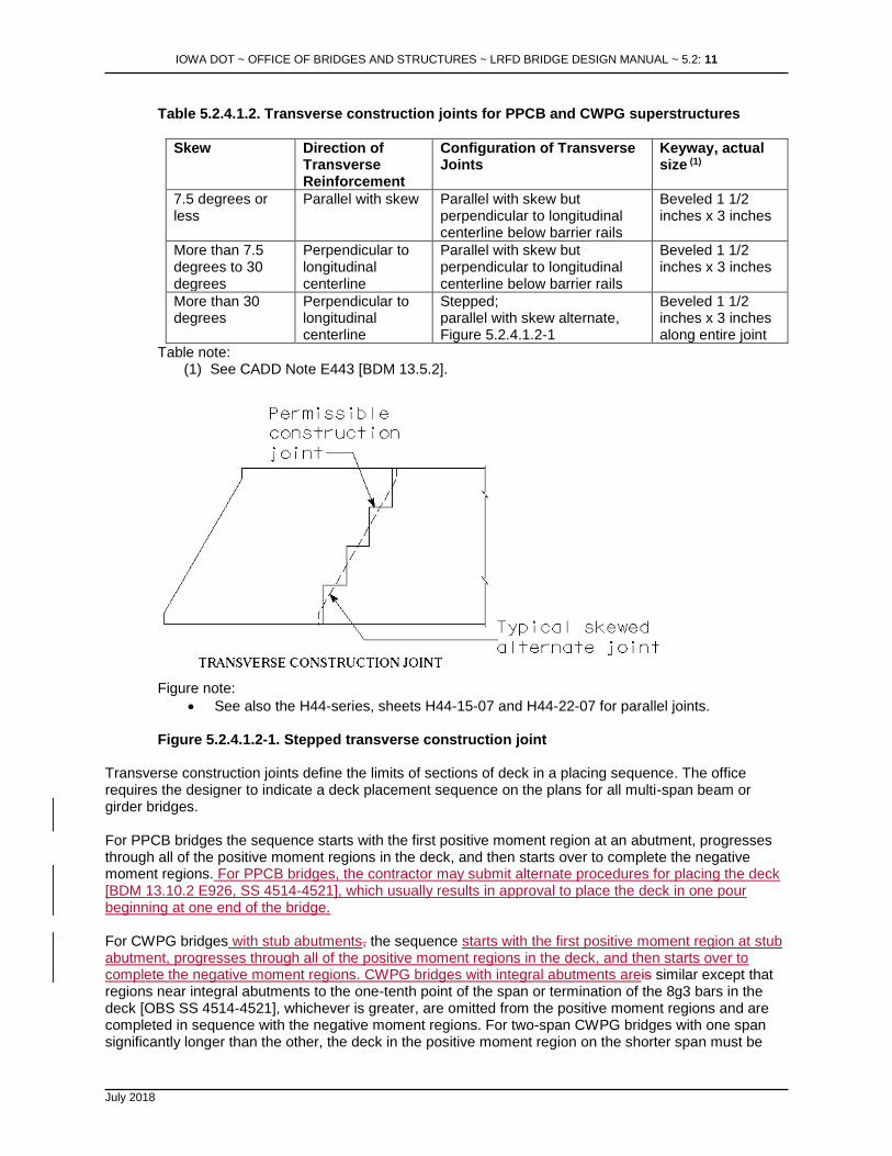
Stepped; parallel with skew alternate, Figure 5.2.4.1.2-1
Beveled 1 1/2 inches x 3 inches along entire joint
Table note: (1) See CADD Note E443 [BDM 13.5.2].
Figure note:
• See also the H44-series, sheets H44-15-07 and H44-22-07 for parallel joints. Figure 5.2.4.1.2-1. Stepped transverse construction joint
Transverse construction joints define the limits of sections of deck in a placing sequence. The office requires the designer to indicate a deck placement sequence on the plans for all multi-span beam or girder bridges. For PPCB bridges the sequence starts with the first positive moment region at an abutment, progresses through all of the positive moment regions in the deck, and then starts over to complete the negative moment regions. For PPCB bridges, the contractor may submit alternate procedures for placing the deck [BDM 13.10.2 E926, SS 4514-4521], which usually results in approval to place the deck in one pour beginning at one end of the bridge. For CWPG bridges with stub abutments, the sequence starts with the first positive moment region at stub abutment, progresses through all of the positive moment regions in the deck, and then starts over to complete the negative moment regions. CWPG bridges with integral abutments areis similar except that regions near integral abutments to the one-tenth point of the span or termination of the 8g3 bars in the deck [OBS SS 4514-4521], whichever is greater, are omitted from the positive moment regions and are completed in sequence with the negative moment regions. For two-span CWPG bridges with one span significantly longer than the other, the deck in the positive moment region on the shorter span must be

IOWA DOT ~ OFFICE OF BRIDGES AND STRUCTURES ~ LRFD BRIDGE DESIGN MANUAL ~ 5.2: 12
July 2018
placed first to prevent uplift, and a note shall be placed on the plans [BDM 13.10.2 E1040A]. A similar note shall be provided for two-span CWPG bridges with equal spans [BDM 13.10.2 E1040B]. For a single span welded plate girder bridge with integral abutments, the placing sequence will be similar to the sequence for a two-span bridge. The positive moment region shall be placed first, and regions near the integral abutments to the one-tenth point of the span or termination of the 8g3 bars, whichever is greater, shall be placed second. The designer shall include on the plans a note similar to the note for two-span bridges [BDM 13.10.2 E1040B]. Restricting the pour sequence note on SS 4553 may be necessary for CWPG bridges with three or more spans when any of the following apply:
• Alternate sequences could subject end span(s) to potential uplift.
• Alternate sequences could subject girders to stress conditions that are not acceptable (or not previously analyzed).
• Bridge geometry is such that the volume of concrete in the largest adjacent "positive + negative + positive" moment region exceeds about 500 CY.
• Curved structures with variable width and/or discontinuous beam lines.
• Designer has reason to believe that certain common alternate deck sequences could be structurally unacceptable.
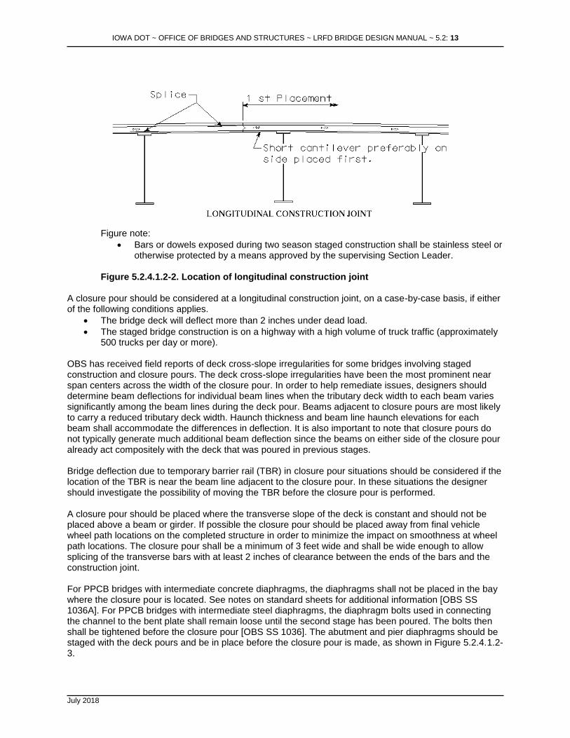
In such cases the designer should modify the pour sequence note to specifically indicate why alternate pour sequences are not permitted. Doing so helps to ensure the contractor does not assume alternate procedures will be permitted. For PPCB bridges, the contractor may submit alternate procedures for placing the deck [SS 4514-4521], which usually results in approval to place the deck in one pour beginning at one end of the bridge. The designer shall provide a longitudinal construction joint near the centerline of the bridge whenever staged construction is required, and any bars or dowels that will be exposed, for more than one construction season, before the second stage is constructed shall be stainless steel or otherwise protected by a method approved by the supervising Section Leader. Epoxy coatings have a very limited lifetime when exposed to the weather and thus are not acceptable for bars or dowels exposed for more than a few weeks. The exposed transverse stainless steel reinforcing shall generally be lapped with transverse epoxy coated steel reinforcing on each side of the staged longitudinal construction joint. The designer also should provide a permissible longitudinal construction joint whenever the out-to-out deck width exceeds 80 feet for constant and tapered width bridges. If the roadway is tapered the construction joint should be aligned to provide one constant width and one tapered longitudinal section. For a permissible construction joint the designer should note on the plans that the contractor has the option to propose a construction sequence that eliminates the joint. In all cases the construction joint should be considered along with a closure pour, which is discussed below. If only a construction joint is necessary, it should be located between the 0.2 and 0.3 points of the deck span between beam or girder flanges as shown in Figure 5.2.4.1.2-2 and placed to miss the longitudinal reinforcement. Preferably the joint also should be 5 feet from the centerline of the bridge to miss the parabolic deck crown. If spliced, transverse reinforcing bars should be spliced at points of minimum stress. If space is limited with staged construction, the splice for top and bottom bars may be placed near the longitudinal construction joint.
IOWA DOT ~ OFFICE OF BRIDGES AND STRUCTURES ~ LRFD BRIDGE DESIGN MANUAL ~ 5.2: 13
July 2018
Figure note:
• Bars or dowels exposed during two season staged construction shall be stainless steel or otherwise protected by a means approved by the supervising Section Leader.
Figure 5.2.4.1.2-2. Location of longitudinal construction joint
A closure pour should be considered at a longitudinal construction joint, on a case-by-case basis, if either of the following conditions applies.
• The bridge deck will deflect more than 2 inches under dead load.
• The staged bridge construction is on a highway with a high volume of truck traffic (approximately 500 trucks per day or more).
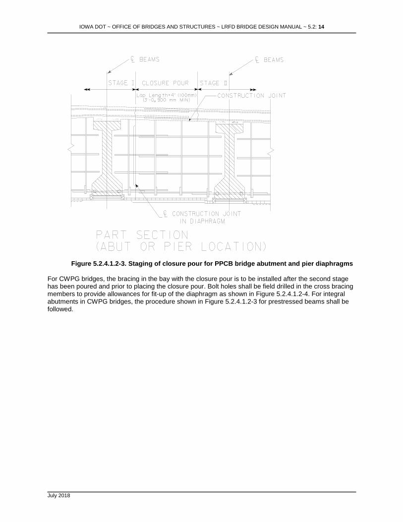
OBS has received field reports of deck cross-slope irregularities for some bridges involving staged construction and closure pours. The deck cross-slope irregularities have been the most prominent near span centers across the width of the closure pour. In order to help remediate issues, designers should determine beam deflections for individual beam lines when the tributary deck width to each beam varies significantly among the beam lines during the deck pour. Beams adjacent to closure pours are most likely to carry a reduced tributary deck width. Haunch thickness and beam line haunch elevations for each beam shall accommodate the differences in deflection. It is also important to note that closure pours do not typically generate much additional beam deflection since the beams on either side of the closure pour already act compositely with the deck that was poured in previous stages. Bridge deflection due to temporary barrier rail (TBR) in closure pour situations should be considered if the location of the TBR is near the beam line adjacent to the closure pour. In these situations the designer should investigate the possibility of moving the TBR before the closure pour is performed. A closure pour should be placed where the transverse slope of the deck is constant and should not be placed above a beam or girder. If possible the closure pour should be placed away from final vehicle wheel path locations on the completed structure in order to minimize the impact on smoothness at wheel path locations. The closure pour shall be a minimum of 3 feet wide and shall be wide enough to allow splicing of the transverse bars with at least 2 inches of clearance between the ends of the bars and the construction joint. For PPCB bridges with intermediate concrete diaphragms, the diaphragms shall not be placed in the bay where the closure pour is located. See notes on standard sheets for additional information [OBS SS 1036A]. For PPCB bridges with intermediate steel diaphragms, the diaphragm bolts used in connecting the channel to the bent plate shall remain loose until the second stage has been poured. The bolts then shall be tightened before the closure pour [OBS SS 1036]. The abutment and pier diaphragms should be staged with the deck pours and be in place before the closure pour is made, as shown in Figure 5.2.4.1.2-3.
IOWA DOT ~ OFFICE OF BRIDGES AND STRUCTURES ~ LRFD BRIDGE DESIGN MANUAL ~ 5.2: 14
July 2018
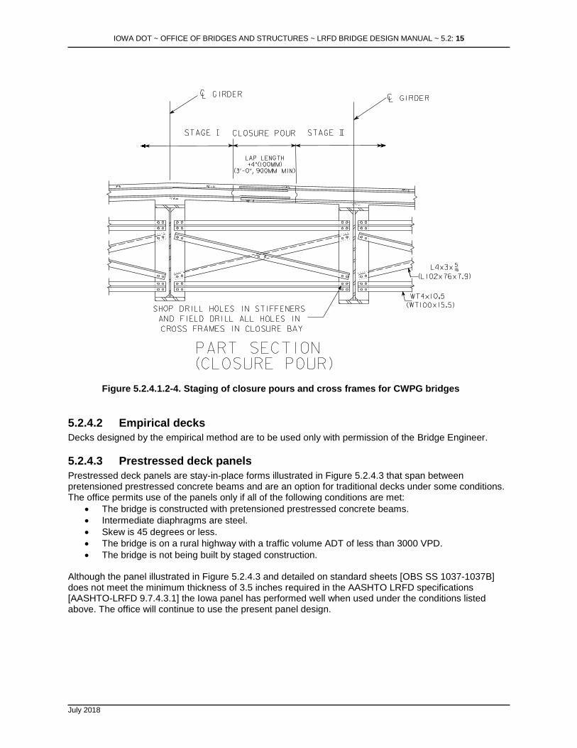
Figure 5.2.4.1.2-3. Staging of closure pour for PPCB bridge abutment and pier diaphragms For CWPG bridges, the bracing in the bay with the closure pour is to be installed after the second stage has been poured and prior to placing the closure pour. Bolt holes shall be field drilled in the cross bracing members to provide allowances for fit-up of the diaphragm as shown in Figure 5.2.4.1.2-4. For integral abutments in CWPG bridges, the procedure shown in Figure 5.2.4.1.2-3 for prestressed beams shall be followed.
IOWA DOT ~ OFFICE OF BRIDGES AND STRUCTURES ~ LRFD BRIDGE DESIGN MANUAL ~ 5.2: 15
July 2018
Figure 5.2.4.1.2-4. Staging of closure pours and cross frames for CWPG bridges
5.2.4.2 Empirical decks
Decks designed by the empirical method are to be used only with permission of the Bridge Engineer.
5.2.4.3 Prestressed deck panels
Prestressed deck panels are stay-in-place forms illustrated in Figure 5.2.4.3 that span between pretensioned prestressed concrete beams and are an option for traditional decks under some conditions. The office permits use of the panels only if all of the following conditions are met:
• The bridge is constructed with pretensioned prestressed concrete beams.
• Intermediate diaphragms are steel.
• Skew is 45 degrees or less.
• The bridge is on a rural highway with a traffic volume ADT of less than 3000 VPD.
• The bridge is not being built by staged construction. Although the panel illustrated in Figure 5.2.4.3 and detailed on standard sheets [OBS SS 1037-1037B] does not meet the minimum thickness of 3.5 inches required in the AASHTO LRFD specifications [AASHTO-LRFD 9.7.4.3.1] the Iowa panel has performed well when used under the conditions listed above. The office will continue to use the present panel design.

IOWA DOT ~ OFFICE OF BRIDGES AND STRUCTURES ~ LRFD BRIDGE DESIGN MANUAL ~ 5.2: 16
July 2018
Figure 5.2.4.3. Prestressed deck panel The decision to prepare plans allowing use of prestressed deck panels shall be made by the Office of Bridges and Structures. The decision to permit the use of panels not allowed as an alternate on the plans, but requested by the contractor, shall be made by the Office of Construction after consulting with the Office of Bridges and Structures. The panels are intended to serve as a form and working platform during construction and to serve compositely with the cast-in-place concrete as the bridge deck in the completed superstructure. The prestressing and reinforcement in the panels replaces the two bottom layers of reinforcement in the traditional cast-in-place concrete deck. To ensure continuity of the panel reinforcement in the transverse direction the panels are fabricated with hooked #3 epoxy coated bars that embed in the cast-in-place concrete above each beam. Fiberboard strips of varying heights are glued to the top edges of prestressed beams in order to elevate the 3-inch thick panels to the required haunch dimension. The top two layers of deck reinforcing are placed above the panels, and all four layers of reinforcing are placed on the deck overhangs. To complete the deck, a minimum of 5 inches of concrete is cast on top of the panels. The panels shall be at least 28 days old at the time the deck is cast.
5.2.4.3.1 Analysis and design

IOWA DOT ~ OFFICE OF BRIDGES AND STRUCTURES ~ LRFD BRIDGE DESIGN MANUAL ~ 5.2: 17
July 2018
5.2.4.3.1.1 Design criteria
Construction loading for the panels shall include panel weight, deck reinforcement, plastic concrete, and a 0.050 ksf construction live load. The load for the composite panel and cast-in-place deck shall include panel and deck weight, a future wearing surface of 0.020 ksf, HL-93 loading, and dynamic load allowance.
5.2.4.3.1.2 Materials
Concrete for the precast prestressed concrete deck panels shall have a minimum strength of 4.5 ksi at release and a minimum 28-day strength of 6.0 ksi. Prestressing strands shall be 3/8 inch diameter ASTM A416 Grade 270 low relaxation strands with an initial tension of 16.1 kips per strand, 70% of the guaranteed ultimate tensile strength (GUTS). Welded wire fabric shall be deformed and shall meet ASTM A 497 [OBS SS 1037, 1037B]. Reinforcement shall be ASTM A 615/A 615M, ASTM A 996/A 996M, or ASTM A 706/A 706M Grade 60.
5.2.4.3.1.3 Additional considerations
When the prestressed panels are allowed as an alternate, plan quantities shall be determined assuming a full depth deck. Payment to the contractor, even if the option to use precast panels is chosen, shall be based on the plan quantities and contract bid price.
5.2.4.3.2 Detailing
The office has prepared standard sheets showing details for the panels for spans to 7 feet and for spans of 7 to 10 feet [OBS SS 1037-1037B]. The office requires that shop drawings showing layout and construction details of the deck panels be submitted for approval. Dimensional tolerances shall be as shown on standard sheets [OBS SS 0137, 1037B]. When the prestressed panel alternate is shown on the plans the designer shall note the adjustments to deck concrete and epoxy coated reinforcement as follows.
• On the general notes and quantities sheet, include notes for reductions in structural concrete and epoxy coated reinforcing steel.
• On the superstructure bar list sheet, include a table of adjustments [OBS SS 1037B].
• On the beam sheet include a note for modified stirrups [OBS SS 1037B]. Although a contractor who uses the prestressed panel alternate needs the information on the adjustments to concrete and reinforcing for construction, the basis of payment is the cast-in-place deck design shown on the plans [IDOT SS 2425.05].
5.2.4.4 Two-course decks
Although the office policy for typical bridges is to use a single course, 8-inch thick deck [BDM 5.2.4.1], that policy does not apply for all bridges. For special designs, the designer may consider a two-course deck. The two-course deck requires approval of the Chief Structural Engineer or the Assistant Bridge Engineer.
5.2.4.4.1 Analysis and design
The two-course deck shall be designed and constructed according to the following policies.
• No load shall be included in the design for a future wearing surface. At such time that the wearing surface no longer is serviceable, the entire upper course of the deck will be removed and replaced without adding load to the structure.

IOWA DOT ~ OFFICE OF BRIDGES AND STRUCTURES ~ LRFD BRIDGE DESIGN MANUAL ~ 5.2: 18
July 2018
• The upper course of the deck shall be two inches thick and may be considered DC dead load.
• The upper course shall not be considered as composite with floor beams or girders.
• The lower, structural course of the deck shall be at least 8 inches thick, which shall be the design thickness. Thicknesses greater than 8 inches shall be used as required for relatively long deck spans.
• Where appropriate shear connection is provided (positive bending regions), the lower, structural course may be considered composite with floor beams or girders.
If the bridge with the two-course deck has a sidewalk with no overlay, allowance for a future wearing surface in the sidewalk area needs to be included in the dead load (DW).
5.2.4.4.2 Detailing
In the lower course, cover above the top mat of reinforcement shall be 2.0 inch. The designer shall include a plan note for the concrete finish on the lower course [BDM 13.3.2, E234]. If the bridge with the two-course deck has a sidewalk with no overlay, cover of 2.0 inch will not be adequate in the sidewalk area or the deck overhang. Separate transverse bars in the sidewalk area need to be placed in order to achieve 2.5-inch cover, as for single course decks.