Embed Size (px)
Citation preview

990002-001, Revision C PMA Response 16 JUN 2020 445 PM_Final Response_PMA Page | 1
Table of contents Introduction ..................................................................................................................................... 5
ReActiv8 components ......................................................................................................................... 5 How to use this document .................................................................................................................. 6
Safety information............................................................................................................................ 7 Label symbols ..................................................................................................................................... 7 Battery disposal guidelines ................................................................................................................. 9 Indications for use .............................................................................................................................. 9 Contraindications ............................................................................................................................... 9 Warnings............................................................................................................................................. 9
Electromagnetic interference (EMI) .............................................................................................. 9 Other ........................................................................................................................................... 11
Precautions ....................................................................................................................................... 11 Electromagnetic Interference (EMI) ............................................................................................ 12 Electromagnetic interference (EMI) from household items ........................................................ 14 Considerations for patient selection ........................................................................................... 14 Sterilization, storage and handling .............................................................................................. 15 System components .................................................................................................................... 16 System implant ............................................................................................................................ 18 Programming ............................................................................................................................... 19 Activator and Magnet .................................................................................................................. 19 Patient activities .......................................................................................................................... 19
Component return and disposal ....................................................................................................... 20 Adverse Event Summary ................................................................................................................... 22 Potential Benefits ............................................................................................................................. 23 Instructions to patients .................................................................................................................... 23
Device description ...........................................................................................................................24 ReActiv8 overview ............................................................................................................................ 24
Implantable components of the ReActiv8 system ....................................................................... 24 External components of the ReActiv8 system ............................................................................. 24
ReActiv8 implantable pulse generator (IPG)..................................................................................... 24 ReActiv8 leads .................................................................................................................................. 25 Lead accessories ............................................................................................................................... 26 Lead delivery system ........................................................................................................................ 26 Application Software and Programmer Wand .................................................................................. 27 ReActiv8 Activator ............................................................................................................................ 27 ReActiv8 Magnet .............................................................................................................................. 28 Package contents .............................................................................................................................. 28
ReActiv8 IPG kit ........................................................................................................................... 28 ReActiv8 Lead kit ......................................................................................................................... 28 ReActiv8 Activator kit .................................................................................................................. 28 ReActiv8 Magnet kit .................................................................................................................... 28 ReActiv8 Torque Wrench ............................................................................................................. 28

Page | 2 990002-001, Revision C PMA Response 16 JUN 2020_445 PM_Final Response_PMA
ReActiv8 Programmer Wand ....................................................................................................... 28 ReActiv8 Application Software .................................................................................................... 29
Product materials ............................................................................................................................. 29 Implant procedure ...........................................................................................................................30
Implant Summary ............................................................................................................................. 30 Patient preparation .......................................................................................................................... 30 Package opening / product handling ................................................................................................ 30 Lead placement ................................................................................................................................ 31 Creating the IPG pocket .................................................................................................................... 33 Tunnelling the Lead .......................................................................................................................... 34 Connecting and implanting the IPG .................................................................................................. 35 Check system integrity...................................................................................................................... 36 Completing the implant procedure .................................................................................................. 36
Explant procedure ...........................................................................................................................37 Removing the IPG ............................................................................................................................. 37 Removing the leads .......................................................................................................................... 37
Programming the ReActiv8 IPG........................................................................................................39 Introduction ...................................................................................................................................... 39 Stimulation Parameters .................................................................................................................... 39
Cycle and session ......................................................................................................................... 40 System Diagnostics Data Collection .................................................................................................. 42
Programmer Wand indicators ..................................................................................................... 43 Preparing the ReActiv8 Programmer Wand and commercially available laptop computer for use ..................................................................................................................................................... 43
Logging into the ReActiv8 Application Software............................................................................... 43 Navigation, parameters and buttons ................................................................................................ 43
Main program tab ........................................................................................................................ 44 Command buttons ....................................................................................................................... 44 Parameter constraints, and warnings .......................................................................................... 45 Stimulation mode and configuration ........................................................................................... 46 Session parameters ..................................................................................................................... 48 Impedance logging ...................................................................................................................... 49
Temporary program tab ................................................................................................................... 49 Temporary mode ......................................................................................................................... 49 Command buttons ....................................................................................................................... 50
Impedance screen tab ...................................................................................................................... 50 Command buttons ....................................................................................................................... 50
Data Review tab................................................................................................................................ 51 Command buttons ....................................................................................................................... 51
Data Graphs tab ................................................................................................................................ 52 Command buttons ....................................................................................................................... 52 X-Axis time interval ...................................................................................................................... 52
Log grid ............................................................................................................................................. 52 Constraints window .......................................................................................................................... 52 Menu Bar .......................................................................................................................................... 52

990002-001, Revision C PMA Response 16 JUN 2020 445 PM_Final Response_PMA Page | 3
File menu ..................................................................................................................................... 52 Tool bar ....................................................................................................................................... 53 View menu ................................................................................................................................... 53 Tools menu .................................................................................................................................. 54 Log menu ..................................................................................................................................... 54 Help menu ................................................................................................................................... 55 Information Bar ........................................................................................................................... 55
Interrogation and IPG states ............................................................................................................. 55 IPG states .......................................................................................................................................... 56 Stimulation testing ........................................................................................................................... 57
Interrogate the IPG ...................................................................................................................... 57 Verify IPG–Lead connections ....................................................................................................... 57 Prepare for stimulation testing ................................................................................................... 57 Perform Threshold testing ........................................................................................................... 57 Stimulation program verification ................................................................................................. 58 Permanently programming the selected parameters ................................................................. 58 Measure impedance and verify IPG time .................................................................................... 59 Ending a programming session .................................................................................................... 59 Verify changes have been programmed ...................................................................................... 59 Review session history ................................................................................................................. 59
Administering a session .................................................................................................................... 60 Using the Activator and Magnet .................................................................................................. 60
Troubleshooting ..............................................................................................................................61 Telemetry related troubleshooting. ................................................................................................. 61 Changing programmable parameters-related troubleshooting ....................................................... 62 Programmer Wand troubleshooting ................................................................................................ 62 Activator and Magnet troubleshooting ............................................................................................ 62 Service Information .......................................................................................................................... 63
Radio Equipment (RE) …………………………………………………………………………………………………………………..61 Appendix A: ReActiv8 IPG specifications ..........................................................................................65 Appendix B: Programmer Wand Specifications ................................................................................68 Appendix C: ReActiv8 Lead specifications .........................................................................................69 Appendix D: Declarations ................................................................................................................71 Appendix E: Clinical Summary………………………………………………………………………………………………………..77 Index ...............................................................................................................................................85

Page | 4 990002-001, Revision C PMA Response 16 JUN 2020_445 PM_Final Response_PMA
Table of figures
Figure 1: ReActiv8 Lead distal end showing electrodes, tines and end-cap ........................................... 25 Figure 2: ReActiv8 Lead proximal end showing connector terminals and set-screw retainer ............... 26 Figure 3: Suture sleeve ........................................................................................................................... 26 Figure 4: Activator .................................................................................................................................. 27 Figure 5: Stimulation waveform and rate .............................................................................................. 40 Figure 6: Stimulation Cycle .................................................................................................................... 40 Figure 7: Stimulation Session ................................................................................................................. 41 Figure 8: Example of Programmer Main Window .................................................................................. 44 Figure 9: Stimulation configuration controls ......................................................................................... 48 Figure 10: Lead – proximal end .............................................................................................................. 69 Figure 11: Lead – distal end ................................................................................................................... 69 Figure 12: Lead dimensions – distal end ................................................................................................ 69 Figure 13: Patient Disposition through 1 year ……………………………………………………………………78 Figure 14: Summary of Efficacy Data at Day 120 and 1 Year …………………………………………………………….. 79
Table of tables Table 1: ReActiv8 IPG Programmable Parameters………………………………………………………………………………46 Table 2: ReActiv8 IPG nominal mechanical and electrical specifications ............................................... 65 Table 3: ReActiv8 IPG Programmable Parameters ................................................................................. 65 Table 4: Battery indicators ................................................................................................................... 665 Table 5: IPG Longevity .......................................................................................................................... 665 Table 6: Conditions for longevity calculations ..................................................................................... 676 Table 7: Programmer Wand nominal specifications ............................................................................ 687 Table 8: Lead summary specification ................................................................................................... 709 Table 9: Lead materials ........................................................................................................................ 709 Table 10: Declarations – IPG and Activator Electromagnetic emissions ................................................ 70 Table 11: Declarations –Programmer Wand Electromagnetic emissions .............................................. 71 Table 12: Declarations – IPG and Activator Electromagnetic immunity............................................... 732 Table 13: Declarations –Programmer Wand Electromagnetic immunity ............................................. 732 Table 14: Declarations – IPG, Programmer Wand and Activator Electromagnetic immunity .............. 743 Table 15: Declarations – IPG, Programmer Wand and Activator Separation distances between portable and mobile RF communications equipment ........................................................................................ 776 Table 16: Serious Device- or Procedure-Related Events through Day 120…………………………..………………80 Table 17: Serious Unrelated Events through 1 Year…………………………………………………………………………….81 Table 18: Study Related Adverse Events through 1 Year………………………………………………………..…………..82 Table 19: Study Related Adverse Events through 1 Year…………………………………………………………………….84

990002-001, Revision C PMA Response 16 JUN 2020 445 PM_Final Response_PMA Page | 5
Introduction ReActiv8 is an implantable electrical stimulation system designed to stimulate the medial branch of the dorsal ramus nerves to cause contractions of lumbar multifidus muscles. Clinical studies have shown that twice-daily sessions of repetitive contractions can improve back pain, the disabling effects of back pain, and quality of life.
ReActiv8 components The implanted ReActiv8 components comprise ReActiv8 Implantable Pulse Generator (IPG) and two ReActiv8 stimulation leads, and suture sleeves. Each lead has a terminal at the proximal end which connects to the IPG, and electrodes at the distal end which deliver the electrical stimulation pulses to the medial branch of the dorsal ramus, such that electrical stimulation will cause contraction of the lumbar multifidus muscles. The provided implant tools facilitate placement of the electrodes.
Three external components can be used to interact with the IPG:
1. ReActiv8 Application Software and ReActiv8 Programmer Wand (used in conjunction with a commercially available laptop computer) used to program the stimulation parameters for the IPG.
2. ReActiv8 Activator, to start and stop a stimulation session. 3. ReActiv8 Magnet, to start or stop a session as a backup to the Activator.
NOTE: For Activator and Magnet instructions, refer to ReActiv8 User Manual.

Page | 6 990002-001, Revision C PMA Response 16 JUN 2020_445 PM_Final Response_PMA
How to use this document This Implant and Programming Manual describes the ReActiv8 implantable electrical stimulation system and provides implant and programming instructions. Refer to the User Manual for instructions on controlling stimulation sessions with the Activator or Magnet.
The “ReActiv8 Implant and Programming Manual” consists of the following sections.
1. The “Implant procedure” section provides detailed instructions for the implantation of the leads and IPG.
2. The “Programming ReActiv8 IPG” section provides detailed instructions for programming the parameters controlling the stimulation and diagnostic functions.
3. Appendices which provide reference information, including a Clinical Summary in Appendix E.

990002-001, Revision C PMA Response 16 JUN 2020 445 PM_Final Response_PMA Page | 7
Safety information Carefully read all contraindications, warnings, precautions, considerations for patient selection and instructions before use. Follow all operating, maintenance, and installation procedures as described in this manual. Failure to do so may result in patient or operator harm.
Safety may be compromised if the procedures used to operate and maintain the ReActiv8 system are different than those specified in the manuals. Anyone who performs the procedures must be appropriately trained and qualified.
Label symbols
CE mark of conformity with the identification of the notified body authorizing use of the mark.
Lot number
Model Number
Serial Number
Temperature limitations for transport
Sterilized using ethylene oxide
Use-by date
Do not re-sterilize
Do not use if package is damaged
Consult Instructions for Use
Manufacturing Date
Manufacturer
Page | 8 990002-001, Revision C PMA Response 16 JUN 2020_445 PM_Final Response_PMA
Caution
Non-ionizing electromagnetic radiation
Standby
Stop
Start
Telemetry status indicator
Session status indicator
Battery condition indicator
Type BF Applied Part
For USA audiences only
Do not reuse
Ingress protection rating
Connector
Length
Diameter
Polarity
Quantity

990002-001, Revision C PMA Response 16 JUN 2020 445 PM_Final Response_PMA Page | 9
Battery disposal guidelines The ReActiv8 Activator is supplied with two AA batteries. The Activator package is labeled in accordance with European Council directives 2002/96/EC and 2006/66/EC. These directives call for separate collection and disposal of electrical and electronic equipment and batteries. Sorting such waste and removing it from other forms of waste lessens the contribution of potentially toxic substances into municipal disposal systems and into the larger ecosystem.
Indications for use The ReActiv8 System is indicated for bilateral stimulation of the L2 medial branch of the dorsal ramus as it crosses the L3 transverse process as an aid in the management of intractable chronic low back pain associated with multifidus muscle dysfunction, as evidenced by imaging or physiological testing in adults who have failed therapy including pain medications and physical therapy and are not candidates for spine surgery.
Contraindications ReActiv8 is contraindicated for patients who are:
Unable to operate the system
Unsuitable for ReActiv8 implant surgery
Warnings ReActiv8 therapy has not been evaluated in patients with evidence on an MRI scan of a pathology that may be amenable to surgery (e.g., severe stenosis, moderate to severe scoliosis).
Electromagnetic Interference (EMI) Electromagnetic interference from electrical or magnetic fields generated by equipment found in the home, work, medical or public environments may interact with or disrupt the function and operation of ReActiv8. The ReActiv8 system includes features that provide a measure of protection from EMI, and most electrical devices and magnets encountered in a normal day are unlikely to affect the operation of the system. However, sources of strong EMI can result in the following effects:
Serious patient injury or death, resulting from heating of the implanted components of the ReActiv8 system, leading to damage to surrounding tissue.
Damage to implantable components, resulting in a loss of function that may require surgical replacement.

Page | 10 990002-001, Revision C PMA Response 16 JUN 2020_445 PM_Final Response_PMA
Operational changes to the ReActiv8 IPG, causing it to turn Stimulation ON or OFF (particularly if the IPG is enabled for Magnet use), or to reset, resulting in loss of stimulation and requiring reprogramming.
EMI from the following medical procedures or equipment may damage the device, interfere with device operation, or cause harm to the patient. If these procedures are required, follow the guidelines below.
Diathermy therapy – Safety of diathermy with an implanted ReActiv8 has not been evaluated. Do not use short-wave diathermy, microwave diathermy, or therapeutic ultrasound diathermy (all now referred to as diathermy) on patients implanted with a ReActiv8. Energy from diathermy can be transferred through the implanted system and cause tissue damage at the location of the implanted leads, resulting in severe injury or death.
Diathermy should not be used because it may damage the IPG components. This damage could result in loss of function, requiring additional surgery. Injury or damage can occur during diathermy treatment whether the system is turned on or off. All patients should be advised to inform their healthcare professionals that they should not be exposed to diathermy treatment.
Magnetic resonance imaging – Safety of MRI with an implanted ReActiv8 has not been evaluated. Do not use MRI on patients who have been implanted with the ReActiv8 system. The large magnetic fields and RF energy produced by MRI equipment may cause serious adverse effects from heating of the implanted IPG and leads, perhaps resulting in permanent injury to the surrounding tissue or permanent damage to the implanted device.
Defibrillation/cardioversion – When a patient is in ventricular or atrial fibrillation, the first consideration is patient survival. External defibrillation or cardioversion can damage the ReActiv8 IPG. It may also cause induced currents in the leads that can injure the patient. Minimize the current flowing through the ReActiv8 system by following these guidelines:
– If possible, program the ReActiv8 IPG Mode to OFF.
– Position the defibrillator paddles as far from the ReActiv8 system as possible.
– Position the defibrillation paddles perpendicular to the ReActiv8 lead path.
– Use the lowest clinically appropriate energy output for defibrillation.
– After defibrillation or cardioversion, verify proper device operation and perform a stimulation test. If an anomaly is detected, corrective actions may include lead repositioning or replacement and/or device reprogramming or replacement.

990002-001, Revision C PMA Response 16 JUN 2020 445 PM_Final Response_PMA Page | 11
Electrocautery and radio frequency (RF) ablation – Electro-surgery devices should not be used in close proximity to the ReActiv8 IPG or Lead(s). Contact between a lead and the electrosurgical instrument can cause direct stimulation of a nerve and can result in severe injury to the patient. Electro-surgery devices may also damage the lead or IPG and cause a loss of stimulation.
If electrosurgical cautery or RF ablation cannot be avoided, observe the following precautions to minimize complications:
1. Program the ReActiv8 IPG Mode to OFF. 2. Avoid direct contact between the cautery equipment or ablation catheter and the
implanted ReActiv8 IPG or Leads. 3. Use a bipolar electro-cautery system if possible. 4. Use short, intermittent bursts at the lowest possible energy levels. 5. Verify proper operation of ReActiv8 and perform a stimulation test immediately
following the procedure. If an anomaly is detected, corrective actions may include lead repositioning or replacement and/or device reprogramming or replacement.
ReActiv8 interaction with other active implantable devices – Safety of the ReActiv8 system has not been evaluated when used in combination with active implantable devices (e.g. pacemaker, defibrillator, spinal cord stimulation). There may be undesirable interactions between the stimulation pulses of the ReActiv8 system and the other active implantable device.
Other Case damage – If the ReActiv8 IPG case is pierced or ruptured, severe burns could
result from exposure to battery chemicals.
Precautions Do not crush, puncture, or burn the IPG – risk of explosion or fire.
Do not incinerate or cremate the ReActiv8 IPG – risk of explosion.
Do not reuse any implantable device or implantable accessory after exposure to body tissues or fluids because the functionality of the component cannot be guaranteed.
Laptop computer battery maintenance or replacement should only be performed by authorised personnel.

Page | 12 990002-001, Revision C PMA Response 16 JUN 2020_445 PM_Final Response_PMA
Electromagnetic Interference (EMI) EMI from the following equipment is unlikely to affect the ReActiv8 system if the guidelines below are followed:
Computed tomographic X-ray (CT scan) – If the patient undergoes a CT scan procedure, turn the IPG Mode to OFF. After completing the procedure, restore the desired parameters.
High output ultrasound and lithotripsy – Program the ReActiv8 IPG Mode to OFF. The use of high output ultrasound devices, such as an electrohydraulic lithotriptor, may damage the electronic circuitry of an implanted IPG. If lithotripsy must be used, do not focus the energy near the IPG.
Electronic article surveillance (EAS) – EAS equipment such as retail theft prevention systems, as well as airport metal detectors may interfere with the ReActiv8 system. Advise patients to walk directly through an EAS system and not remain near an EAS system longer than necessary.
Radiation therapy – Ionizing radiation produced by high energy radiation sources, such as cobalt 60 or gamma radiation, can damage active implantable medical devices. The effect is cumulative and can vary from temporary modifications to irreversible damage, depending on dose rate and total radiation. Note that this effect may not be immediately detected. If radiation therapy is required, program the IPG to OFF and protect the implanted device with lead shielding. Verify IPG operation after exposure. If tissue near the implant site must be irradiated, IPG relocation should be considered.
Static magnetic fields – Avoid equipment or situations where there is a risk of exposure to static magnetic fields greater than 10 gauss or 1 mT. Sources of static magnetic fields include, but are not limited to, audio loudspeakers, magnetic badges, or magnetic therapy products. If patients cannot avoid magnetic fields, the Magnet Effect parameter should be programmed to None.
Bone growth stimulators – Safety has not been established for bone growth stimulators in patients who have a ReActiv8. If bone growth stimulators must be used, turn the ReActiv8 IPG Mode to OFF. Keep external magnetic field bone growth stimulator coils as far away from the IPG as possible. When using either an implantable or external bone growth stimulator, ensure that both the bone stimulator and ReActiv8 are working as intended.
Diagnostic ultrasound probes – Turn the ReActiv8 IPG Mode to OFF. Keep the probe away from the IPG. An average acoustic intensity of greater than 500 watts per meter squared should not be used.

990002-001, Revision C PMA Response 16 JUN 2020 445 PM_Final Response_PMA Page | 13
Electrolysis – Safety has not been established for electrolysis therapy in patients who have a ReActiv8. If electrolysis must be used, turn the ReActiv8 IPG Mode to OFF. Keep the electrolysis wand as far away from the IPG as possible.
Electroconvulsive therapy (ECT) – Safety has not been established for ECT in patients who have a ReActiv8. Induced electrical currents may cause heating, especially al the lead electrode site, resulting in tissue damage.
Transcranial magnetic stimulation (TMS) – Safety has not been established for TMS in patients who have a ReActiv8. Induced electrical currents may cause heating, especially at the lead electrode site, resulting in tissue damage.
Externally-applied monitoring equipment – Externally-applied patient monitoring equipment, such as an ECG machine or Holter recorder, may detect ReActiv8 stimulation pulses.
Explosive or flammable gases – The Programmer and Activator are not certified for use in the presence of a flammable anaesthetic mixture with air or an oxygen or nitrous oxide rich environment. The consequences of using the programmer near flammable atmospheres are unknown.
Electromagnetic field devices – Exercise care or avoid the following equipment or environments which may affect normal operation of the ReActiv8 system due to strong magnetic, electrical and electromagnetic fields:
– Antennas of ham radios should be kept at least 4 m (13 feet) away
– Antennas of citizens band (CB) radios should be kept at least 2.5 m (8 feet) away
– Cellular phones should be kept at least 1.5 m (5 feet) away
– Wi-Fi® radio equipment should be kept 75 cm (30 inches) away
– Bluetooth® radio equipment should be kept 20 cm (8 inches) away
– Electric arc welding equipment
– Electric induction heaters used in industry to bend plastic
– Large electric motors or alternators
– Electric steel furnaces
– High-power amateur radio transmitters
– High-voltage areas
– Power amplifiers

Page | 14 990002-001, Revision C PMA Response 16 JUN 2020_445 PM_Final Response_PMA
– Magnetic degaussing equipment
– Magnets or other equipment that generates strong magnetic fields
– Microwave communication transmitters
– Perfusion systems
– Resistance welders
– Television and radio transmitting towers
If it is suspected that equipment is interfering with ReActiv8, the following is recommended:
1. Move away from the equipment or object. 2. If possible, turn OFF the equipment or object. 3. Then, if necessary, use the Magnet or Activator to disable stimulation. 4. Inform the equipment owner or operator of the occurrence.
If the above actions do not resolve the effects of the interference, or there is a suspected change after exposure to EMI, then the patient should contact their physician.
If magnetic fields cannot be avoided, the Magnet Effect parameter should be programmed to None.
Laser procedures – Turn the ReActiv8 IPG Mode to OFF. Keep the laser directed away from all components of ReActiv8.
Electromagnetic interference (EMI) from household items Most household appliances and equipment that are working properly and grounded properly will not interfere with ReActiv8. Many household items contain magnets or generate magnetic fields that are strong enough to activate the magnet switch inside the IPG, which can be programmed to start or stop therapy.
If interference is suspected, instruct the patient to move away or turn off the household item.
Considerations for patient selection ReActiv8 is not suitable for every patient with chronic low back pain. Suitable candidates for ReActiv8 have:
Moderate to severe chronic low back pain and disability despite medical management and attempting at least one course of physical therapy.
Ability to operate the system.

990002-001, Revision C PMA Response 16 JUN 2020 445 PM_Final Response_PMA Page | 15
The safety and effectiveness of ReActiv8 has not been established for:
Pregnant women (including effects on a foetus, or during childbirth)
Pediatric use (patients under the age of 22)
Patients with BMI >35
Patients with scoliosis or stenosis
Patients with arachnoiditis or syringomyelia
Patients with worse leg pain than back pain
Patients with radiculopathy below the knee
Patients with previous back surgery below T8
Patients with any spinal fusion
Patients with previous thoracic or lumbar sympathectomy
Physician training Implanting physicians – Implanting physicians must have undergone training on
surgical procedures and device implantation.
Prescribing physicians – Prescribing physicians should be experienced in the diagnosis and treatment of chronic low back pain and should be familiar with using ReActiv8.
Sterilization, storage and handling Package or component damage – Do not implant a ReActiv8 IPG or Lead if the sterile
package or components show signs of damage, if the sterile seal is ruptured, or if contamination is suspected for any reason. Return any suspect components to Mainstay Medical for evaluation.
Re-sterilization – Do not re-sterilize or reuse any devices for any reason, because of risk of infection and malfunction of the devices.
Single-use, sterile device – The sterilized components of the ReActiv8 system and accessories are intended for single use only.
Storage temperature – Store all sterile products, including the IPG, implantable Leads, and accessories, between 5°C and 30°C. Exposure to temperatures outside this range may result in damage.

Page | 16 990002-001, Revision C PMA Response 16 JUN 2020_445 PM_Final Response_PMA
Storage temperature – Store the following non-sterile products, including the Programmer Wand, Magnet and Activator, between -10oC and +55oC. Exposure to temperatures outside this range may result in damage.
Storage humidity – Store components between 15% and 93% humidity (non-condensing). Exposure to humidity outside this range may result in damage.
Storage environment – Store ReActiv8 components and their packaging where they will not come into contact with liquids of any kind.
Operating temperature – Do not use the Programmer Wand or Activator when the air temperature is greater than 40oC or below 10oC.
Expiration date – An expiration date (or “use-by” date) is printed on the packaging for sterile products. Do not use the system if the use-by date has expired.
Cleaning external system components – The recommended cleaning process is to use a soft cloth, lightly dampened with distilled water, ethanol (96%) or isopropyl alcohol (98%), to wipe the exterior case of the Activator, Activator Antenna and Programmer Wand as needed. The same technique can be used with a solution of up to a 50% water / 50% bleach mixture. Do not clean with any water solution containing > 50% bleach.
Cleaning instructions for laptop computer – The recommended cleaning process for the laptop computer case and keyboard is to wipe it using a soft, dust-free cloth lightly dampened with distilled water or isopropyl alcohol as needed. The cleaning process for the display is to gently wipe using a dry soft lint-free cloth as needed. Avoid spraying cleaner directly onto the display or keyboard.
System components Component failure – As with any electronic device, the ReActiv8 might unexpectedly
fail or stop working at any time due to a random component fault, battery failure, exposure to extreme environmental interferences or environmental conditions. These factors may reduce device longevity, effectiveness and cause changes in the performance characteristics.
Care and handling of components – Use care when handling system components prior to implantation. Excessive heat, excessive traction, excessive bending, excessive twisting, or the use of sharp instruments may damage and cause failure of the components.
Exposure to body fluids or saline – Prior to connection of the leads to the IPG, exposure of the metal contacts to body fluids or saline can lead to compromised performance. If such exposure occurs, clean the affected parts with sterile, deionized water and dry completely prior to lead connection.

990002-001, Revision C PMA Response 16 JUN 2020 445 PM_Final Response_PMA Page | 17
System components – The use of components or accessories from other manufacturers with the ReActiv8 system may result in failure to deliver stimulation, damage to the system and increased risk to the patient.
System testing – The system should always be tested after implantation and before the patient leaves the surgery suite.
Battery-powered equipment – An implanted lead constitutes a direct, low resistance current path to the body. Use only battery-powered devices and instruments when the lead connections are exposed, such as during the implant procedure. Caution should be taken to properly ground all AC powered equipment used in the vicinity of the patient.
Protective earth integrity – Use only battery-powered devices and instruments if the protective earth conductor integrity is in doubt.
Electrical isolation during implant – Do not allow the patient to have contact with grounded electrically powered equipment that might produce electrical current leakage during implant.
Infection – It is important to follow proper infection control procedures. Infections related to system implantation might require that the device be explanted.
The Programmer Wand is NOT STERILE – The ReActiv8 Programmer Wand is not sterile or sterilisable. It should not be placed in the sterile field unless placed in a sterile sleeve.
Product materials – The ReActiv8 system has materials that come in contact or may come in contact with tissue. Potential for an allergic reaction to these materials should be determined before the system is implanted.
Programmer Wand USB connection – The USB connector of the Programmer Wand should not be installed in a USB port capable of delivering greater than 10 W at 5 V. The Programmer Wand uses less than 0.5 W at 5 V.
Laptop computer external connection – Do not connect any equipment to the laptop computer provided with the ReActiv8 Application Software and Programmer Wand with a separate mains supply connection (an AC powered printer, for example) while the Programmer Wand is connected to the laptop computer.
Laptop computer grounding – To avoid the risk of electric shock, the laptop computer must only be connected to a mains supply (AC power) with protective earth. If protective earth is not available, the laptop computer must be operated on battery power only. Do not tamper with the protective earth connection.
Laptop computer and AC adapter – The AC adapter is designed only to be used with the laptop computer and the provided detachable AC adapter cord. Do not use any

Page | 18 990002-001, Revision C PMA Response 16 JUN 2020_445 PM_Final Response_PMA
other AC adapter with the laptop computer provided with the ReActiv8 Application Software and Programmer wand. Do not use the AC adapter with any other equipment. Do not use the AC adapter or detachable AC adapter cord if damage is suspected. The laptop computer and AC adapter should be kept 1.5 meters from the operating table.
Strangulation by cable – When operating the Activator, keep the antenna cable away from the neck to avoid strangulation.
Equipment Modification – The equipment is not serviceable. To prevent injury or damage to the system, do not modify the equipment. If service is needed, return the equipment to Mainstay Medical.
Software Updates – Should a software update be required, Mainstay will contact customers to coordinate the timing and logistics of the update procedure. Mainstay will provide prior written notification to customers prior to any software update. Always verify Mainstay representative credentials prior to allowing access to the ReActiv8 Programmer System.
System implant Do not kink, or stretch the lead body, as this may result in damage to the lead and
compromise function.
Do not advance the introducer sheath without the dilator inside the sheath, as this may result in damage and prevent deployment of the lead.
Do not use surgical instruments (e.g.: forceps) to handle the lead. The forces applied by surgical instruments may compress the lead, resulting in compromised performance and conductor, or insulation damage.
Do not bend, kink or use surgical instruments on the stylet, which may result in damage. Use care when reinserting a stylet. Too much pressure on the stylet could damage the lead, resulting in intermittent or loss of stimulation.
Do not use saline or other ionic fluids at or near any of the electrical connections (i.e. lead terminal or IPG header), as this could result in compromised performance.
Do not place sutures directly around the lead body, since sutures may cut the lead insulation.
Before opening the lead package, verify the package model number, that the kit is within its expiration (use-by) date, and that the packaging has not been damaged or compromised in any way.

990002-001, Revision C PMA Response 16 JUN 2020 445 PM_Final Response_PMA Page | 19
When removing the lead from the sterile tray, carefully remove the distal end from the retaining tube to avoid damaging the fixation tines. Carefully inspect the lead for damage after removing it from the sterile package.
If the operating field is contaminated (e.g. with blood) wipe gloves, lead, stylet, and introducer before proceeding with the implant. Failure to do so may result in difficulty placing the lead.
Do not use long-acting muscle relaxants or paralytics during the anaesthetic procedure as it could suppress muscle contractions during stimulation, confounding system testing.
Programming High stimulation outputs – Stimulation at high outputs may cause unpleasant
sensations. If unpleasant sensations occur, stimulation should be adjusted appropriately.
Activator and Magnet Activator handling – To avoid damaging the Activator, do not immerse it in liquid; do
not clean it with nail polish remover, mineral oil, or similar substances; avoid spilling fluids on it; and do not drop it or mishandle it in a way that may damage it.
Magnet disable – If the ReActiv8 IPG Magnet Effect has been programmed to NONE, the patient must have an Activator to start or prematurely stop Sessions.
Magnet may damage items – Do not place the ReActiv8 Magnet on or near computer monitors, magnetic storage disks or tapes, televisions, credit cards, or other items affected by strong magnetic fields. If the magnet is too close, these items may malfunction or be damaged.
Patient activities Patient activity/equipment operation-Please read the following important information about activities to avoid.
Patients should be advised to avoid activities requiring excessive twisting or stretching, that may put undue stress on the implanted components of the neurostimulation system for the first few weeks after implant.
Patients should be advised to avoid activities that include sudden, excessive, or repetitive bending, twisting, bouncing, or stretching that may results in stress on the leads which could result in migration or fracture. This can result in loss of stimulation, intermittent stimulation, stimulation at the fracture site, and additional surgery.

Page | 20 990002-001, Revision C PMA Response 16 JUN 2020_445 PM_Final Response_PMA
During stimulation, patients should be advised to not operate potentially dangerous equipment, such as power tools, automobiles, or other motor vehicles, to not climb ladders or participate in other activities where postural change or an abrupt movement could alter the perception of stimulation intensity and cause the patient to fall or lose control of equipment or vehicles or injure others.
Component manipulation by the patient (Twiddler's syndrome) – Patients should be advised to avoid manipulating or rubbing the ReActiv8 through the skin. Manipulation may cause component damage, lead dislodgement, skin erosion, infection.
Scuba diving or hyperbaric chambers – Patients should not dive below 5 meters (16 feet) of water or enter hyperbaric chambers above 1.48 atmospheres absolute (ATA). Pressures below 5 meters (16 feet) of water (or above 1.48 ATA) could damage the ReActiv8 IPG. Before diving or using a hyperbaric chamber, patients should discuss the effects of high pressure with their physician.
Skydiving, skiing, or hiking in the mountains – High altitudes should not affect the ReActiv8 system; however, the patient should consider the movements involved in any planned activity and avoid putting undue stress on the implanted system. Patients should be aware that during skydiving, the sudden jerking that occurs when the parachute opens may cause lead dislodgement or fractures, which may require surgery to repair or replace the lead.
Areas with Protective Signs – Patients should not enter areas protected by warning notices prohibiting entry by people fitted with an implantable device such as a pacemaker.
Emergency procedures – The patient should be instructed to designate a representative (family member or close friend) to notify any emergency medical personnel of their implanted system, if emergency care is required. Each patient will be provided with a Medical Identification Card that will inform emergency medical personnel that the patient has a ReActiv8 implanted. The patient should be advised to use caution when undergoing any procedure that could include RF, microwave ablation, defibrillation or cardioversion.
Component return and disposal When explanting an IPG and/or leads (e.g. replacement, cessation of stimulation, or post-mortem), or when disposing of accessories, follow these guidelines:
If possible, return the explanted device(s) with completed paperwork to Mainstay Medical for analysis and disposal. Examination of explanted components can provide information for continued improvement in system reliability.

990002-001, Revision C PMA Response 16 JUN 2020 445 PM_Final Response_PMA Page | 21
Do not autoclave any components of ReActiv8 or expose any components to ultrasonic cleaners.
Dispose of any unreturned components according to local environmental regulations; in some countries, explanting a battery-powered implantable device post-mortem is mandatory.

Page | 22 990002-001, Revision C PMA Response 16 JUN 2020_445 PM_Final Response_PMA
Adverse Event Summary The implantation of ReActiv8 involves risks similar to those of peripheral nerve stimulators. In addition to risks commonly associated with surgery, implantation or use of ReActiv8 includes, but is not limited to, the following risks:
Adverse Events (AEs) associated with the surgical procedure, including implant, revision, replacement and removal.
Acute or persistent pain including more pain than anticipated after surgery or worsened low back pain.
Accidental injury to adjacent tissues, e.g. piercing structures such as muscle, blood vessels or organs.
Infection, including local infection of the surgical site, systemic infection and sepsis
Slow, abnormal or inadequate wound healing including wound dehiscence (slow healing), which may require surgical repair.
Tissue reaction to the presence of the implanted device or materials in/on the implanted device such as response to residual material on device or an allergic response, e.g. previously unknown nickel or titanium allergy. Reaction may be local or systemic.
Nerve irritation, impingement or damage, including that resulting from mechanical presence of device, exposure to electricity including electrical stimulation, or migration of the leads, suture sleeve or IPG. This may lead to pain, paralysis, sensory deficits or changes to bowel, bladder or reproductive function.
Device extrusion.
Erosion, threatened erosion or fistula formation in skin overlying device components.
Excessive fibrotic tissue growth.
Hematoma, seroma, cyst or swelling.
Acute or persistent pain including worsened low back pain and/or pain and discomfort due to presence of the device.
Undesired sensations such as uncomfortable paraesthesia, numbness, vibration, pressure, prickling, or uncomfortable contraction of the multifidus.
Overstimulation of tissue, resulting in symptoms such as painful muscle contraction, paraesthesia, jolts or shocks. In addition, injuries that occur as a consequence of stimulation, e.g. accidents that occur as a result of being startled.

990002-001, Revision C PMA Response 16 JUN 2020 445 PM_Final Response_PMA Page | 23
Tissue damage due to mechanical presence of device, or exposure to electricity including electrical stimulation.
Contraction of muscles other than the target muscle(s).
Muscle fatigue, spasm or injury.
Stiffness, including restricted motion due to adhesions to the device.
Inability to deliver stimulation, including inadequate doses of stimulation. Causes include lead migration, device malfunction or exposure to electromagnetic fields, e.g. security screening devices.
Undesired electrical stimulation.
Inability to stop therapy, with possible sequelae such as anxiety, restriction of movement, pain, muscle fatigue, postural changes, difficulty in walking, sitting or physical activity.
Accidents, injuries, body movements, body positions or biological process which lead to device complications. Examples include a fall which may cause damage to the IPG; sit-ups or severe coughing leading to migration of the lead; or fracture of bones leading to device migration or damage.
Patients may also undergo medical and/or surgical intervention (such as revision or explant) to treat the issues identified above.
Potential Benefits The potential benefits associated with ReActiv8 include:
• Reduction in severity of low back pain; • Improvement in the ability to handle regular daily activities (reduction of disability); and • Improvement in quality of life.
Instructions to patients Inform the patient about the risks and benefits, implantation procedure, follow-up requirements, and self-care responsibilities associated with the ReActiv8 system.
Provide the patient with instructions, including the User Manual, regarding the operation and care of the ReActiv8 system. Provide guidelines regarding what circumstances the physician should be contacted regarding suspected problems.

Page | 24 990002-001, Revision C PMA Response 16 JUN 2020_445 PM_Final Response_PMA
Device description
ReActiv8 overview The ReActiv8 system consists of an Implantable Pulse Generator (IPG), Leads, surgical tools and accessories, Application Software, Programmer Wand, Activator, Magnet and Tunneler.
The ReActiv8 IPG, Torque Wrench and Leads, and the Mainstay Tunneler have been sterilized using ethylene oxide (EO) gas.
Implantable components of the ReActiv8 system The implantable components of the ReActiv8 system are:
Model 5100 ReActiv8 Implantable Pulse Generator
Model 8145 ReActiv8 Implantable Stimulation Lead and Suture Sleeves – 45 cm
Model 8165 ReActiv8 Implantable Stimulation Lead and Suture Sleeves – 65 cm
External components of the ReActiv8 system The external components of the ReActiv8 system are:
Model 7000 ReActiv8 Activator
Model 4000 ReActiv8 Magnet
Model 5500 Torque Wrench
Version 1.0.1.6 (English) and 1.0.1.9 (Multilanguage) Application Software
Model 6000 Programmer Wand
Model TUN1 Mainstay Tunneler
Note: The ReActiv8 Programmer Wand and Application Software are provided with a commercially available laptop computer and AC adapter.
ReActiv8 Implantable Pulse Generator (IPG) The ReActiv8 IPG is designed to deliver electrical stimulation to nerves. The electrical signals travel from the IPG, through the leads, to electrodes placed near nerves. The ReActiv8 Activator enables the patient to control delivery of stimulation.
The ReActiv8 IPG is a two-channel, programmable device that accepts two four-electrode leads. The IPG has an epoxy resin header with two suture holes which may be used to

990002-001, Revision C PMA Response 16 JUN 2020 445 PM_Final Response_PMA Page | 25
secure the IPG to the tissue pocket. The electronics and its power source, a lithium chemistry primary cell (non-rechargeable) battery, are encapsulated in a hermetically sealed titanium can.
There are two lead connectors in the IPG (one for each of the two leads), consisting of four aligned spring contacts that establish the electrical connection with the lead terminal contacts. Each lead is secured by a set-screw engaging an electrically inactive retainer ring on the lead terminal. A torque wrench is included in the IPG package to enable manipulation of the set-screws.
With standard X-ray procedures, the radiopaque code inside the header of the IPG is visible. It identifies the manufacturer and model number of the IPG. For the ReActiv8 IPG, the code has the format XX MIPG, where XX are the last two digits of the year the ReActiv8 IPG was manufactured. For example, if a ReActiv8 IPG has a manufacturing date of in 2015, the radiopaque code is 15 MIPG.
ReActiv8 Leads Each lead comprises a distal end with electrodes, a proximal end with a connector terminal, and a lead body ( Figure 1). The distal end contains four platinum iridium electrodes, an inactive end cap and two opposing sets of three-point tines. The tines are located on either side of the most distal electrode. They fold along the lead body during insertion of the lead through the introducer and deploy to engage tissue and secure the lead upon introducer withdrawal. The placement of the tines and their opposing orientations provides bi-directional fixation and is designed to reduce the risk of lead movement.
Figure 1: ReActiv8 Lead distal end showing electrodes, tines and end-cap
On the proximal end the lead has four nickel cobalt alloy terminal contacts separated by spacers, and an electrically inactive set-screw retainer (Figure 2). Contacts and electrodes are joined by a lead body consisting of individually coated spiral wound insulated wires, and

Page | 26 990002-001, Revision C PMA Response 16 JUN 2020_445 PM_Final Response_PMA
the whole lead is covered by polyurethane tubing. The lead has a lumen closed at the distal end which accepts a stylet.
Figure 2: ReActiv8 Lead proximal end showing connector terminals and set-screw retainer
The terminal contacts connect to the aligned spring contacts in the IPG header to establish the electrical connection. Each lead is secured in the IPG by a set-screw engaging the retainer on the lead terminal.
Lead Accessories The lead is packaged with two accessories: a suture sleeve and a stylet. The stylet is a straight 316L Stainless Steel wire which can be inserted into the lead lumen to provide additional stiffness and ease passage of the lead through the introducer. The suture sleeve (Figure 3) may be used to attach the lead body to the fascia and features a 1.3mm inner-diameter. The suture sleeve is moulded out of NuSil MED-4870 silicone rubber.
Figure 3: Suture sleeve
Lead delivery system The lead is designed to be placed using a commercially available 7Fr Introducer Kit and the Mainstay Model TUN1 Tunneler.

990002-001, Revision C PMA Response 16 JUN 2020 445 PM_Final Response_PMA Page | 27
Application Software and Programmer Wand The Programmer Wand is connected via a USB port to a commercially available laptop computer that contains the ReActiv8 Application software. The laptop computer is configured such that it can only be used with the Application Software. The Programmer Wand communicates with the IPG using short-range inductive telemetry. The Application Software provides a user interface that is used to program the IPG (change the value of the programmable parameters), interrogate the IPG (ask for the actual value of the programmable parameters, battery voltage, logged information and IPG status) and read the lead impedance (command the IPG to perform the procedure that allows it to calculate the lead impedance). Refer to the Programming section for more detailed information.
ReActiv8 Activator The Activator is a hand-held device that is used to start and stop stimulation and can be used to check the status of the IPG. The Activator is as illustrated in Figure 4. The Activator consists of a control module attached to an antenna via a cable and communicates with the IPG via short-range inductive telemetry. This configuration allows the user to maintain visual contact with the control module during operation while the antenna is placed over the IPG.
The Activator is powered by 2 AA-type alkaline batteries which are user replaceable.
Figure 4: Activator
Page | 28 990002-001, Revision C PMA Response 16 JUN 2020_445 PM_Final Response_PMA
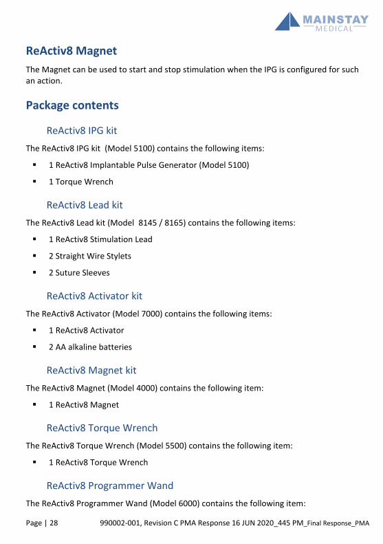
ReActiv8 Magnet The Magnet can be used to start and stop stimulation when the IPG is configured for such an action.
Package contents
ReActiv8 IPG kit The ReActiv8 IPG kit (Model 5100) contains the following items:
1 ReActiv8 Implantable Pulse Generator (Model 5100)
1 Torque Wrench
ReActiv8 Lead kit The ReActiv8 Lead kit (Model 8145 / 8165) contains the following items:
1 ReActiv8 Stimulation Lead
2 Straight Wire Stylets
2 Suture Sleeves
ReActiv8 Activator kit The ReActiv8 Activator (Model 7000) contains the following items:
1 ReActiv8 Activator
2 AA alkaline batteries
ReActiv8 Magnet kit The ReActiv8 Magnet (Model 4000) contains the following item:
1 ReActiv8 Magnet
ReActiv8 Torque Wrench The ReActiv8 Torque Wrench (Model 5500) contains the following item:
1 ReActiv8 Torque Wrench
ReActiv8 Programmer Wand The ReActiv8 Programmer Wand (Model 6000) contains the following item:

990002-001, Revision C PMA Response 16 JUN 2020 445 PM_Final Response_PMA Page | 29
1 ReActiv8 Programmer Wand
ReActiv8 Application Software The ReActiv8 Application Software is supplied on a commercially available laptop computer. CE 0086 mark on the laptop computer applies only to the ReActiv8 Application Software (and not to the laptop computer or other software on the laptop computer).
Product materials The ReActiv8 system is manufactured with materials that come into contact with tissue.
The following materials are intended to come into contact with tissue:
Platinum iridium
Polyurethane
Silicone rubber
Stainless steel
MP35N (alloy)
Titanium
Epoxy resin
The ReActiv8 does not contain phthalates, latex, human blood derivatives or cells or tissues of human or animal origin.

Page | 30 990002-001, Revision C PMA Response 16 JUN 2020_445 PM_Final Response_PMA
Implant procedure
Implant Summary The leads are designed for permanent implant by anchoring the tines on either side of the intertransversarii lateralis lumborum (intertransversarii), with the electrodes placed adjacent to the descending medial branch of the dorsal ramus nerve. The leads are introduced under fluoroscopic visualization using a needle, guide wire, and delivery sheath with dilator.
Leads are placed bilaterally, with the electrodes placed adjacent to the medial branch of the dorsal ramus as it crosses the transverse process at L3. Leads are tunnelled subcutaneously between the lead implant incision and the IPG pocket.
The IPG is placed in a subcutaneous pocket in a location deemed appropriate by the implanting physician, considering the patient’s ability to reach the IPG location for initiation of stimulation with the Activator. It is recommended that an appropriate location be used to minimize tensile forces on the lead during subject movement.
Patient preparation The patient is preferably positioned prone (face down) on an operating table compatible with fluoroscopy, with the spine, hips and knees in approximately the same position as when the patient is standing (i.e. not flexed).
Using standard sterile techniques, carry out the appropriate skin prepping, draping, and injection of local anaesthetic to perform the percutaneous lead placement.
The patient should be anaesthetized as per the physician’s discretion. Long-acting muscle relaxants or paralytics should be avoided during the anaesthetic procedure as it could suppress muscle contractions during stimulation, confounding system testing.
Package opening / product handling Read the label on the product package before opening to ensure you have the right product. Inspect the package carefully to ensure it is intact. Do not use a damaged or opened package. For products that are provided STERILE, introduce the contents into a sterile field: (1) Peel the Tyvek lid from the outer tray, (2) use a sterile handling technique to put the inner tray into sterile field, and (3) peel the Tyvek lid from inner tray to expose the contents. The product should be stored according to the conditions listed on the individual product labels.

990002-001, Revision C PMA Response 16 JUN 2020 445 PM_Final Response_PMA Page | 31
Lead placement The leads should be placed with an insertion point near the midline of the body, with a trajectory such that the electrodes are placed near the medial branch of the dorsal ramus as it crosses the transverse process at L3.
1. Identify the insertion point and make a skin incision at the needle-entry site.
NOTE: The incision should be of sufficient length to allow placement of strain relief and a suture sleeve if deemed necessary.
2. Under fluoroscopy, insert the needle (included in the introducer kit). The tip of the needle should be advanced in a straight trajectory to the cranial edge of the transverse process on which the target nerve lies, and extend through the intertransversarii to the anterior surface of the transverse process.
CAUTION: Avoid steering the needle to correct for misalignment within the needle tract as this may cause lead migration. If the placement of the needle is not at the desired location, the needle should be removed entirely and the procedure started over.
NOTE: After placement, confirm needle location under fluoroscopy in both anterior-posterior and lateral views.
3. Place the guide wire (included in the introducer kit) through the needle.
NOTE: The guide wire should exit the needle in line with the needle. If it does not, it may be necessary to retract the guide wire into the needle and advance the needle slightly (1-2mm) to get penetration through the intertransversarii.
4. Confirm the guide wire position in both anterior-posterior and lateral views and then remove the needle while holding the guide wire stable.
5. Insert the introducer and dilator over the guide wire, following the same path and trajectory as the guide wire to prevent kinking of the guide wire.
6. Confirm placement in both anterior-posterior and lateral views and then remove the guide wire. Remove the dilator and guide wire from the introducer sheath.
7. Insert the lead with the stylet inserted into the introducer. The distal tip of the lead should be advanced to exit the sheath just beyond the anterior surface of the transverse process.

Page | 32 990002-001, Revision C PMA Response 16 JUN 2020_445 PM_Final Response_PMA
NOTE: Do not remove the stylet before inserting the lead into the introducer. Without the stylet, lead stiffness may not be sufficient to advance the lead into the correct position.
8. Once lead placement is confirmed via fluoroscopy in both anterior-posterior and lateral views, remove the introducer and withdraw the lead stylet from the lead.
NOTE: If the lead does not advance beyond the tip of the introducer, the introducer may not be placed deeply enough. Remove the lead from the introducer and after reinserting the dilator, advance the introducer slightly and reattempt lead placement.
CAUTION: If the lead advances beyond the introducer sheath tip at any point in the procedure and repositioning is determined to be necessary, the lead should not be pulled back into the introducer as this may damage the tines. The introducer should be withdrawn over the lead body and the lead removed by applying gentle axial loading to the lead body, gripping the lead as close to the insertion point as possible.
9. Gently tug on the lead body to engage the distal tines on the anterior surface of the intertransversarii and the proximal tines on the posterior surface of the intertransversarii, and to ensure the tines are engaged. If the lead can be easily removed, the tines are not engaged.
NOTE: It should be possible to feel the engagement of the tines, and movement of the lead in both directions should be limited.
10. Once the position is confirmed, provide strain relief in the lead body just caudal to the insertion point.
11. The provided suture sleeve may be used to anchor the lead.
12. Confirm the final lead position fluoroscopically using anterior-posterior and lateral views and by checking impedance and muscle twitch thresholds using the ReActiv8 IPG.
CAUTION: Attempting to slide the suture sleeve over the lead terminal can cause damage to the lead, resulting in intermittent or no delivery of stimulation. The suture sleeve is slit across the full length and designed to be folded open and popped sideways onto the lead body.
NOTE: Refer to the section “Stimulation Testing” in the manual.

990002-001, Revision C PMA Response 16 JUN 2020 445 PM_Final Response_PMA Page | 33
13. If stimulation thresholds or lead impedances are NOT satisfactory, remove the lead by cutting the sutures around the suture sleeve (if a suture sleeve was used) and remove the lead by applying slow and steady traction on the proximal lead body as close to the insertion point as possible.
CAUTION: If the lead is removed, visually inspect the distal fixation tines for any sign of damage. Do not reuse the lead if damaged.
14. To replace the lead after removal, repeat the lead placement and stimulation testing instructions above.
15. For the second lead, repeat the lead placement and stimulation testing instructions above.
Creating the IPG pocket Once both leads are placed and anchored, create a subcutaneous pocket for the IPG.
16. Administer local anaesthetic (if necessary) at the selected IPG pocket site.
17. Make an incision just large enough to allow placement of the IPG.
18. Form the IPG pocket using blunt dissection.
CAUTION: Ensure that the IPG is placed no deeper than 4 cm below the skin and is parallel to the skin with the labelling language facing the skin. If the IPG is too deep or is not parallel to the skin, telemetry may be compromised.

Page | 34 990002-001, Revision C PMA Response 16 JUN 2020_445 PM_Final Response_PMA
Tunnelling the Lead 1. Once the IPG pocket is created, tunnel the leads subcutaneously from the implant sites
to the IPG pocket.
NOTE: A standard subcutaneous tunnelling tool or introducer set can be used to facilitate lead tunnelling, provided the tunnelling tool or introducer are capable of passing the 1.3 mm diameter lead body.
2. Identify the tunnelling route between the lead incision and the IPG pocket.
CAUTION: Avoid sharp bends or kinks when routing the lead, as this may damage the lead and result in loss of stimulation.
3. Assemble the tunnelling tool per the manufacturers’ instructions.
Note: If bending of the tunnelling tool is required to conform to the patient’s contour, identify a tunnelling tool which includes a malleable insert.
4. Insert the tunnelling tool at one incision and tunnel subcutaneously to the other incision.
NOTES: Avoid the lower thoracic ribs during tunnelling. If the tunnelling tool does not extend to the lead site, make an intermediate incision.
5. Guide the tunnelling tool subcutaneously along the tunnelling route by pushing the skin over the tunnelling tool tip until the tip of the tunnelling tool sheath is exposed at the incision.
6. Follow the manufacturer’s instructions for removal of the installed tunnelling tip and/or tunnelling insert.
7. Gently insert the proximal end of the lead(s) through the tunnelling tool sheath to the IPG pocket.
8. Slide the tunnelling tool sheath over the lead and out of the subcutaneous IPG pocket, leaving the lead in place.
9. Repeat the tunnelling steps above for the second lead (if necessary), following as close as possible to the subcutaneous path of the first lead.

990002-001, Revision C PMA Response 16 JUN 2020 445 PM_Final Response_PMA Page | 35
Connecting and implanting the IPG 1. Once tunnelled to the IPG pocket, the leads are connected to the IPG. The left channel
is numbered 1-4 and the right channel 5-8.
a. The following graphic is provided on the IPG to aid in visualization of lead connection.
CAUTION: Before connecting the lead to the IPG, wipe off any body fluids and dry all connections. Fluids in the connections may result in stimulation at the connection site, intermittent stimulation, or loss of stimulation.
2. Visually verify complete insertion of the lead terminals into the IPG header. The lead terminal contacts should be covered by the IPG contact blocks.
NOTES: If the lead will not insert completely, the setscrews may need to be retracted. To retract the setscrews, insert the torque wrench into the seal plug and rotate the
setscrews counter clockwise; however, do not remove the setscrews from the connector block.
3. Tighten the header set-screws using the provided torque wrench. An audible “click” is the indication of complete engagement of the set-screw.
CAUTIONS: Tightening the set-screws with the lead not fully inserted may result in
insulation and/or conductor damage resulting in intermittent or no delivery of stimulation.
Only use the torque wrench provided in the IPG package or the Model 5500 accessory. Use of other torque wrenches may induce damage in the lead terminal which could cause insulation or conductor damage and make the system inoperable or prevent removal of the lead terminal from the IPG.
Ensure that the torque wrench is in line with the screw – do not apply lateral (bending) pressure on the torque wrench as it may lead to damage.
4. Once both leads are connected, place the IPG into the pocket. The IPG incorporates two suture holes on the IPG header which may be used to secure the IPG to the fascia.

Page | 36 990002-001, Revision C PMA Response 16 JUN 2020_445 PM_Final Response_PMA
NOTE: It is recommended to secure the IPG using both suture holes to minimize the risk of IPG rotation, flipping over and migration.
CAUTIONS: Do not coil excess leads and leave lying over the IPG between the IPG and
the skin. Lead loops should not be smaller than 2.0 cm in diameter. Failure to follow this instruction may lead to potential damage during IPG replacement surgery, potential kinking of the lead, and interference with telemetry.
Placing the coiled excess leads in a separate pocket formed adjacent to the IPG may reduce the potential for lead/IPG abrasion.
Check system integrity 1. Prior to closing the incisions, lead placement should again be confirmed using lateral
and anterior-posterior (AP) fluoroscopy views and system integrity should be reconfirmed using the Programmer to interrogate the IPG.
NOTE: The IPG should be in the pocket during system integrity checking.
CAUTION: To use the non-sterile Programmer Wand in a sterile field, place a sterile barrier between the patient and the Wand to prevent infection. Do not sterilize any part of the ReActiv8 Programmer or Wand. Sterilization may damage the Programmer or Wand.
2. To ensure proper connection of each lead to the IPG, use the ReActiv8 Application Software to check the battery status, and measure the electrode impedances.
Completing the implant procedure 1. After confirmation of acceptable lead placement both radiographically and electrically,
close the incisions and dress using routine techniques.

990002-001, Revision C PMA Response 16 JUN 2020 445 PM_Final Response_PMA Page | 37
Explant procedure In the event that the system needs to be explanted (e.g. as a result of infection), the procedure described below is recommended to remove all implanted components. The procedure can be modified as necessary, for example to remove just the IPG in the event of IPG replacement at end of battery life. Fluoroscopic imaging capabilities may facilitate the procedure.
Removing the IPG 1. With the patient suitably anaesthetized, open the IPG pocket.
2. Cut any sutures securing the IPG to the fascia and dispose of the sutures.
3. Expose the IPG and take it out of the pocket, taking care not to damage or apply tension to the leads.
4. Loosen the set-screws that engage the set-screw retainer on the connector of each lead.
5. Grasp the lead body as close as possible to the IPG header and gently pull the lead terminal from the IPG.
6. Repeat the above step for the second lead.
At this point a new IPG may be connected if required. In this case, refer to the implant section for detailed instructions for procedure completion.
Removing the leads 1. Open the lead pocket over the area of strain relief on each lead.
2. Gently pull the proximal end of the lead through the subcutaneous pathway previously created to the IPG pocket.
3. Cut any sutures and remove any suture sleeves that secure the leads and dispose, ensuring that no remnants of the sutures or suture sleeves remain in the patient.
4. Dissect any fibrotic tissue that has developed around the strain relief in the lead.
5. Pull on the lead to remove it completely.
6. If more than approximately 1.5 kg of force is required to remove the lead, consider using commercially available extraction tools such as dilator sheaths and locking stylets.
7. Once the leads have been removed, inspect them carefully to confirm that all portions of the lead and the tines have been removed.

Page | 38 990002-001, Revision C PMA Response 16 JUN 2020_445 PM_Final Response_PMA
8. If in doubt, consider a surgical cut down procedure to examine the implant location.
NOTE: As is required by regulation in most countries, all explanted components should be decontaminated, and returned in a sealed pouch to Mainstay Medical for returned device analysis.

990002-001, Revision C PMA Response 16 JUN 2020 445 PM_Final Response_PMA Page | 39
Programming the ReActiv8 IPG
Introduction The ReActiv8 Application software and ReActv8 Programmer Wand are supplied with a commercially available laptop computer and are used to program the IPG. The programmer Wand uses short range inductive telemetry to:
Interrogate the IPG – Obtain the values of the programmable parameters, battery voltage, logged information and IPG status.
Program the IPG – Change the values of the programmable parameters.
Measure impedance – Command the IPG to perform the procedure that allows the Programmer to calculate the lead impedance.
For the purposes of this manual, a programming session is any programming interaction with the IPG, including:
Interrogating and reviewing the IPG status, program parameters and stored data.
Permanently programming parameters that control stimulation and diagnostics.
Changing and temporarily programming parameters to test a stimulation mode
Performing system integrity checks and impedance measurements.
Stimulation Parameters A stimulation session is initiated by application of the Activator. During a stimulation session, the ReActiv8 system delivers episodic electrical stimulation. The detailed timing and stimulation intensity is controlled by the program that was stored in the IPG at the time of programming.
The following IPG parameters (see Figure 5) control the energy (charge) and rate of stimulation:
Amplitude – Controls the stimulation pulse Amplitude.
Pulse Width – Controls the stimulation pulse Width.
Rate – Controls the stimulation Rate.

Page | 40 990002-001, Revision C PMA Response 16 JUN 2020_445 PM_Final Response_PMA
Figure 5: Stimulation waveform and rate
Cycle and session A Session consists of a number of Cycles of stimulation. Each Cycle of stimulation consists of a number of stimulation pulses at the programmed Amplitude, with a duration of Cycle-On, plus Cycle-Off. During the Cycle-On time, stimulation Amplitude increases linearly from zero to the programmed Amplitude during an On-Ramp, and decreases from the Stimulation Amplitude to zero during an Off-Ramp, as shown in Figure 6..
Figure 6: Stimulation Cycle
A session consists of a number of stimulation Cycle-On times, separated by a Cycle-Off time. Stimulation during a session starts after a programmable delay, as illustrated in Figure 7. Stimulation during the session stops automatically once the programmable session time is reached. Stimulation can also be stopped manually using the Activator, or using the Magnet if the IPG is programmed to allow it.
Amplitude
Waveform Pulse Width
Time
Charge Balancing
1/Rate
Amplitude
On Ramp Off Ramp
Cycle-On
Stimulation Pulse
Time

990002-001, Revision C PMA Response 16 JUN 2020 445 PM_Final Response_PMA Page | 41
Figure 7: Stimulation Session
Timing of the Session is controlled by the following IPG parameters:
Session Delay – Controls the time between starting the session and the first stimulation pulse.
Session – Controls the duration of the session and is measured from the start of the first Cycle to the end of the last Cycle. The Programmer, Activator or the Magnet can all be used to start or stop a session. Stimulation stops automatically at the conclusion of the Session.
Cycle-On – Controls the duration of each stimulation Cycle.
Cycle-Off – Controls the time between each stimulation Cycle.
On-Ramp – Controls the time over which the stimulation Amplitude reaches its programmed value at the beginning of a Cycle. This allows for a smooth increase in muscle contraction. A sudden increase in stimulation Amplitude may startle the patient or cause temporary discomfort.
Off-Ramp – Controls the time over which the stimulation Amplitude decreases at the end of a Cycle. This allows for a smooth decrease in muscle contraction.
Session started Session stops automatically
Session
Time
Cycle
Cycle On
Cycle Off
Session Delay

Page | 42 990002-001, Revision C PMA Response 16 JUN 2020_445 PM_Final Response_PMA
System Diagnostics Data Collection The IPG records time-stamped data and performs periodic system integrity checks using an internal clock. For each session, the IPG records the following data, which can be downloaded and reviewed using the ReActiv8 Programmer:
Session start time
Termination type (session completed, session aborted)
Duration of stimulation delivery
Impedance of the active electrode configuration for each stimulation channel
Battery voltage
The IPG records the following daily session information, which can be downloaded and reviewed using the ReActiv8 Programmer:
Total Session Time (the total number of session minutes for the entire day)
Number of Daily Sessions (the total number of sessions run for the entire day)
The IPG records the following daily measures (if enabled), independent of sessions. This information can be downloaded and reviewed using the ReActiv8 Programmer:
Battery voltage
Impedance of the active electrode configuration for each stimulation channel
Log Impedance Matrix
The basic programmable parameters, their ranges and nominal values are shown in Appendix A - ReActiv8 IPG Programmable Parameters.

990002-001, Revision C PMA Response 16 JUN 2020 445 PM_Final Response_PMA Page | 43
Programmer Wand indicators The ReActiv8 Programmer Wand uses two visual indicators:
Standby indicator – A single green indicator, which lights up when the USB Wand is connected to the laptop computer and the laptop computer is turned ON.
Signal Strength indicator – An array of 10 indicators (4 green, 3 yellow and 3 red), which provide information on the quality of the telemetry link.
Preparing the ReActiv8 Programmer Wand and commercially available laptop computer for use
1. Verify that the Programmer Wand is connected to a USB port on the laptop computer.
2. Turn on the laptop computer and login to the Application software.
3. If the laptop computer battery is not charged, connect the AC adapter to the wall outlet (AC mains) and the laptop computer.
NOTE: The software displays an error message if the Programmer Wand has not been connected.
Logging into the ReActiv8 Application Software After the laptop computer has been switched on, multiple Windows accounts will be available on the screen.
Select the “Commercial” Windows account (the other Windows accounts are not accessible for commercial use).
Navigation, parameters and buttons The ReActiv8 Application Software user interface consists of five main areas of information and control (Figure 8):
1. Main Window – Within this window, it is possible to toggle between the five application specific screens by selecting their corresponding Tabs: Main Program, Temporary Program, Impedance Screen, Data Review and Data Graphs.
2. Log Grid (right upper pane) – Displays the historical log of all the orders issued by the programmer to a specific device.
3. Constraints Window (right lower pane) – Displays the error and warning messages corresponding to any unverified restriction or warning condition.

Page | 44 990002-001, Revision C PMA Response 16 JUN 2020_445 PM_Final Response_PMA
4. Menu Bar – All the commands are accessible via the Menu Bar, even if they are also present in other places such as toolbars.
5. Toolbar – Provides quick access to frequently used functions.
6. Information Bar – Appears on all programmer screens, directly below the screen tabs. Displays Subject ID, Serial No., Battery and Status.
Figure 8: Example of Programmer Main Window
Main program tab From this screen, all displayed parameters controlling IPG function can be permanently programmed.
Command buttons Blue command buttons on the screen perform the following operations:
Interrogate – Imports the parameter values from the IPG into this screen.
Program – Exports the changed parameter from this screen to the IPG. Once parameter changes have been entered on the screen, the Program button flashes until changes are either cancelled or programmed.
Start Session –Starts a Session.

990002-001, Revision C PMA Response 16 JUN 2020 445 PM_Final Response_PMA Page | 45
Stop Session (or End key on keyboard) – Stops a Session.
Measure Impedance – Performs the impedance measurement of the active channels.
Perform Device Data Backup – Performs IPG and Programmer data backup.
Indicators are displayed across the top panel in all screens.
Parameter constraints, and warnings IPG parameters can be selected from a list which appears when clicking the button next to
or below the parameter label, for example:
The font colour in which the parameter selection is displayed indicates the state of that parameter:
Black – The parameter value is currently permanently programmed and not involved in a restriction listed in the Constraints Window.
Red – The parameter value is involved in an unresolved restriction (error) listed in the Constraints Window, which prevents programming. As a result, the Program buttons remain inactive.
Orange – The parameter value is involved in an unresolved warning listed in the Constraints Window, which does NOT prevent programming. The blue Program button is flashing.
Blue – The parameter value is not constrained in any way. If no constraints remain elsewhere, the blue Program button is flashing and the parameter can be programmed.
The IPG parameters which are programmable from this screen are discussed in the following sections. Those listed as indicators are fixed settings.

Page | 46 990002-001, Revision C PMA Response 16 JUN 2020_445 PM_Final Response_PMA
Stimulation mode and configuration Table 1: ReActiv8 IPG Programmable Parameters
Parameter Programmable range Nominal value (Typical values used in clinical study)
Minimum value
Maximum value
Step
Channel for Terminals 1 - 8
Left, Right Left: T1 - T4 Right: T5 - T8
Polarity for Terminals 1 - 8
Positive, Negative, Disconnected Disconnected
Channel for IPG Can (+ polarity)
Left, Right, Left and Right, Disconnected Disconnected
Amplitude 0.0 mA 7.0 mA 0.1 mA 0.0 mA (2.5 mA) Pulse Width 31 µs 336 µs 31 µs 214 µs (214 µs) Rate 1 Hz 26 Hz 1 Hz 20 Hz (20 Hz) On-Ramp 0 s 5 s 1 s 2 s (2 s) Off-Ramp 0 s 5 s 1 s 2 s (2 s) Cycle-On 2 s 20 s 2 s 10 s (10 s) Cycle-Off 20 s 120 s 2 s 20 s (20 s) Session 1 m, 2 m, 5 m, 10 m, 15 m, 20 m, 25 m, 30 m 30 m (30 m) IPG Mode On, Off Off (On) Stimulation Mode
Left, Right, Bilateral, Seq. L-R, Seq. R-L Bilateral (Bilateral)
Magnet Effect Start/Stop Session, Stop Session Only, None Stop Session Only (Stop Session Only)
Cumulative Max 30 m, 40 m, 1 hr 1 hr (1 hr) Daily Log Time 0 hr 0 m 23 hr 59 m 0 hr 1 m 2 hr 0 m
(2 hr 0 m) Log Impedance Matrix
YES, NO YES (YES)
Matrix Log Period
Each Session, Daily, Weekly Daily (Daily)
Subject ID 12 characters (alpha numeric including “-“) - Transpose L-R YES, NO NO (NO)
IPG Mode – The IPG can be programmed to ON or OFF. When OFF, it will not deliver stimulation.

990002-001, Revision C PMA Response 16 JUN 2020 445 PM_Final Response_PMA Page | 47
Magnet Effect – The response of the IPG to application of the Magnet can be programmed to Stop Session Only (only stops an ongoing session (default)), Start/Stop Session (starts or stops a session) or None (Magnet has no effect on the IPG).
Stimulation Mode – The side and sequence in which stimulation is delivered in a session can be programmed to Left, Right, Bilateral (simultaneously), Sequential Left then Right and Sequential Right then Left.
Rate – Stimulation rate can be programmed to values between 1 and 26 Hz.
Polarity for Terminals 1 - 8 – For each of the electrodes, polarity can be toggled between ‘ ‘(off), + and - by repeatedly clicking on the Polarity Toggles in the graphic representation of the Lead terminal.
Channels for Terminals 1 - 8 – Each of the electrodes can be assigned to one of the two IPG channels L (left) or R (right) by clicking on the Channel Toggles next to the terminal number.
Polarity for IPG Can (Positive polarity) – It is possible to include the IPG Can in the stimulation configuration. Polarity can be toggled between ‘ ‘(off) and + by
repeatedly clicking on the Active Can Toggle .
Amplitude – Pulse Amplitude is independently programmable for the left and right channel to values between 0.0 and 7.0mA. Alternatively, Amplitudes can be incremented or decremented by clicking the up and down arrows.
Pulse width – Pulse Width is independently programmable for the left and right channel to values between 31 and 336 μs.
Offset (stimulation channel L&R) – (Indicator) in seconds. A delay for left and right channel delivery of the pulse train.
Transpose L-R – Moves electrodes 1-4 to the right lead image and moves 5-8 to the left lead image on the Programmer screen. Only available on versions 1.0.1.9 onwards.

Page | 48 990002-001, Revision C PMA Response 16 JUN 2020_445 PM_Final Response_PMA
Figure 9: Stimulation configuration controls
Session parameters Session – The duration of the treatment session is programmable to values between
1 and 30 minutes.
Cycle-On – The duration of the cycling pulse train can be programmed to values between 2 and 20 seconds. Cycle-On includes the programmed On- and Off-Ramp.
Cycle-Off – The duration of the relaxation phase in between cycling pulse trains can be programmed to values between 20 and 120 seconds.
On-Ramp – The time after which the pulse train reaches the full programmed Amplitude can be programmed to values between 0 and 5 seconds. This provides a gradual start to each pulse train. On-Ramp is included in the Cycle-On duration.
Off-Ramp – The time after which the end of pulse train reaches 0mA, measured from the last pulse at full programmed Amplitude. Off-Ramp can be programmed to values
Channel Toggles
Polarity Toggles
Active Can Toggle
Increment and
Decrement
Active Electrode Pair Selection (Temporary Program Screen)

990002-001, Revision C PMA Response 16 JUN 2020 445 PM_Final Response_PMA Page | 49
between 0 and 5 seconds. This provides a gradual finish to each pulse train. Off-Ramp is included in the Cycle-On duration.
Cumulative Max – The maximum cumulative session limit can be programmed to values between 30 minutes to 1 hour over a time span of 1 day.
Lockout Time – (Indicator) 2 hours. The time after a completed session during which stimulation is inhibited.
Session Delay – (Indicator) 40 seconds. The delay between session activation through the patient Activator and delivery of the first pulse train in the Session.
Impedance logging Log Impedance Daily – Programmable to YES or NO. If programmed to YES,
impedance is logged every day, time specified by the Daily Log Time.
Daily Log Time – The time at which the Daily Impedance Log is performed is programmable to a time between 0:00 and 23:59 hr.
Log Impedance Matrix – Programmable to YES or NO. If programmed to YES, impedance for all 64 possible electrode permutations is logged periodically during sessions, daily or weekly, as determined by the Matrix Log Period.
Matrix Log Period – The frequency at which the Log Impedance Matrix is performed is programmable to: Every Session, Daily or Weekly.
Temporary program tab This tab provides access to the Temporary Programming tool, which is used to test stimulation configurations, thresholds and output settings. This is also the screen used for intraoperative testing.
Temporary mode While in Temporary mode, the IPG maintains the telemetry link with the Programmer and accepts modifications to the Amplitude, while delivering continuous stimulation (no Cycle-Off time during temporary mode) in Left, Right, or both channels using a Stimulation Pattern from ‘Stimulation Mode’. The other parameters can be modified only when the continuous stimulation is not being delivered. When the telemetry link is lost for 5 consecutive seconds, the device will execute an Off-Ramp using the programmed settings and stop the stimulation.

Page | 50 990002-001, Revision C PMA Response 16 JUN 2020_445 PM_Final Response_PMA
Command buttons Blue command buttons on the screen perform the following operations:
Start Temporary Program – Initiates an On-Ramp using the programmed On-Ramp parameter and the Temporary Programming Parameters, after which it delivers continuous stimulation in both channels if the programmed Stimulation Mode is Bi-lateral, Left if the Stimulation Mode is Left and in channel Right if the Stimulation Mode is Right.
Stop Temporary Program – Initiates an Off-Ramp using the programmed Off-Ramp parameter; after the Ramp, the device stops the stimulation. Once the Start Temporary Program button has been pressed, the Stop Temporary Program button flashes until the Stop Temporary Program button or the End key on the keyboard is pressed or if the telemetry connection between the Programmer Wand and the IPG is disconnected for more than 5 seconds.
Copy Changed Values to Main Screen – copies all the parameter values from the Temporary Program Screen to the Programmer Main Screen.
Measure Impedance – performs the impedance measurement of the selected terminals.
Load Twitch Test Presets – loads the starting parameters for Onset Twitch testing
Load Tolerability Test Presets – loads the starting parameters for Max Tolerability testing
The following indicator is displayed:
Last Amp Value – Displays the last value of the Amplitude that was programmed before the Stop Temporary Program button or the End key is pressed. The value shown by this indicator is copied to the Programmer Main Screen when Copy Changed Values to Main Screen button is pressed.
Impedance screen tab The Impedance screen allows real time impedance measurements through the IPG.
Command buttons Blue command buttons on the screen perform the following operations:
Measure Impedance Matrix – Measures and displays impedance for all 64 possible electrode permutations.

990002-001, Revision C PMA Response 16 JUN 2020 445 PM_Final Response_PMA Page | 51
Measure Impedance – Measures the impedance for each channel (L and R if selected) between the active electrodes. Terminal selections (Active Electrodes) in this screen do not affect the Main Program Screen.
Impedance values are displayed according to the following convention:
<30 Ohms: the label ‘<30’ is displayed in red.
30 to 149 Ohms: the measured value is displayed in red.
150 to 4999 Ohms: the measured value is displayed in black.
5000 to 12000 Ohms: the measured value is displayed in red.
>12000 Ohms: the label ‘>12000’ is displayed in red.
Data Review tab Data Review provides a mechanism for displaying the Data Storage.
Command buttons Blue command buttons on the screen perform the following operations:
Get Stored Data – Retrieves from the IPG’s memory the stored Daily Impedance of the programmed configuration, Logged Impedance Matrices, Total Daily Session Time and the Number of Daily Sessions.
Left/Right arrows – Increments or decrements the Timestamp of the Daily Data Storage displayed.
Impedance values are displayed according to the following convention:
<30 Ohms: the label ‘<30’ is displayed in red.
30 to 149 Ohms: the measured value is displayed in red.
150 to 4999 Ohms: the measured value is displayed in black.
5000 to 12000 Ohms: the measured value is displayed in red.
>12000 Ohms: the label ‘>12000’ is displayed in red.
Page | 52 990002-001, Revision C PMA Response 16 JUN 2020_445 PM_Final Response_PMA
Data Graphs tab Data Graphs provides a mechanism to graphically display historical data of Daily Session Time and Daily Impedance measures in this screen.
Command buttons The blue command button on the screen performs the following operations:
Get Stored Data – Populates the graphs with the available data of Total Daily Session Time and Daily Impedance retrieved from the IPG’s memory.
X-Axis time interval Selection of the interval displayed on the x-axis is controlled by the Time Window underneath each graph. Using the mouse pointer, grab the slider at each extreme of the window and slide inwards until the desired time interval is displayed.
Log grid The Log grid displays the historical log of all the orders issued by the programmer to each specific device.
Constraints window The message window displays the error and warning messages corresponding to any unverified restriction or warning condition.
NOTE: If you have trouble understanding errors or warning messages, contact your Mainstay Medical representative for assistance.
Menu Bar All the available commands are included in the Menu Bar, even if they are also present in other places such as toolbars or on the main screen. They are organized in the File, View, Tools, Log and Help menus.
File menu The File menu provides access to a drop-down menu with the following commands:
Interrogate – Retrieves all programmed parameters from the IPG.
Program – Programs all changed parameters into the IPG.

990002-001, Revision C PMA Response 16 JUN 2020 445 PM_Final Response_PMA Page | 53
Cancel – Cancels all changed parameters.
Undo – Undoes the last programming command.
Open Settings… – Retrieves values from a saved file.
Save Settings… – Saves current values in a file.
Print Settings… – Print Preview of current parameter values.
Exit – Quits the ReActiv8 Programmer Application.
Tool bar In the tool bar, the following commands are represented by Icon buttons.
Interrogate – Retrieves all programmed parameters from the IPG.
Program – Programs all changed parameters into the IPG.
Cancel – Cancels all changed parameters.
Undo – Undoes the last programming command.
Print – Launches a Print Preview screen that lists all the programmable parameters.
Emergency Stop – Stops all IPG stimulation delivery.
Flag icon (upper right corner of screen) - Allows the selection of local languages
View menu The View menu provides access to a drop-down menu allowing configuration of the following user interface options:
Status Bar – When checked, the Status Bar with date and time is shown at the bottom of the screen.
Log – When checked, the Log Grid is shown on the right upper side of the screen.
Constraints – When checked, the Message Window is shown on the right lower side of the screen.
Standard toolbar – When checked, the Program, Interrogate, Undo and Cancel Icons are shown in in the Toolbar.

Page | 54 990002-001, Revision C PMA Response 16 JUN 2020_445 PM_Final Response_PMA
Tools menu The Tools menu provides access to a drop-down menu with the following commands:
Wand Version – Provides Programmer Wand model, version and serial number.
IPG Version – Provides version information of IPG Telemetry and Therapy firmware.
Time – Allows setting of the device time.
Activator Status – Checks Emulated Activator Status.
Activator Start – Emulates Activator Start.
Activator Stop – Emulates Activator Stop.
Reset – Resets the IPG and the default parameter values are shown on the screen.
Read Data Storage – Reads the IPG statistics and opens a window displaying a table containing the events logged by the device, and for each event its timestamp (format: mm/dd/yy, hh:mm:ss), and the associated information.
Export Data Storage – Exports the Data Storage information to a file of extension ‘.csv’ in the Log folder on the laptop computer.
Clear Data Storage – After user confirmation (“Are you sure to reset the statistics? OK/Close"), resets the device’s counters and recorded events.
Reset Blocked Attempts Counter – After user confirmation (“Are you sure to reset the Blocked Attempts Counter? OK/Close"), resets the device’s blocked attempts counter.
Change Language – Allows the selection of local languages. The Icon is located on the upper right side of the screen.
Log menu The Log menu provides access to a drop-down menu with the following data Log management commands:
Export Log – Exports the log information shown in the current Log Grid to a text file.
Export Programs – Exports current programed settings to a text file.
Log filter – Configures the type of items to be displayed on the log window and to be exported in the log.
Compare Programs – Provides a log of incremental programming changes in subsequent Sessions.
Backup Database – Creates a backup of the log Database in a .backup file.

990002-001, Revision C PMA Response 16 JUN 2020 445 PM_Final Response_PMA Page | 55
Restore Database – Restores the log Database from a .backup file previously generated.
Help menu The Help menu provides the following information:
About… – Displays the version of the Programmer Software and the versions of the model library. It also displays the manufacturer’s contact information: Mainstay Medical Limited, [email protected].
Information Bar The Information Bar appears on all programmer screens, directly below the screen tabs and provides the following information:
Subject ID – Subject identification information. Only available on versions 1.0.1.9 onwards
Serial No. – (Indicator) IPG serial number.
Battery – (Indicator) IPG battery voltage.
Status – (Indicator) IPG Battery Status (OK, ERI (Elective Replacement Indicator), EOL (End of Battery Life).
Interrogation and IPG states After logging in to the software, interrogate the IPG either by clicking the icon in the Tool Bar or the blue Interrogate button on the Main Program screen.
NOTE: Position and hold the Programmer Wand steadily over the IPG during communication between the programmer and IPG.
When interrogation is complete, a pop-up window will display the IPG state and provide pertinent status data when applicable. Also the battery status will be updated.
Close the pop-up window by clicking the Close to Continue button.
1. Verify Subject ID (if applicable) and IPG serial number are correct. 2. Ensure Battery Status is OK. 3. Check the Programming Log and Message Panel for any error messages.

Page | 56 990002-001, Revision C PMA Response 16 JUN 2020_445 PM_Final Response_PMA
IPG states The following IPG states can be shown in the pop-up window:
Safe Mode – Contact Mainstay Medical Representative. An anomaly was detected and the IPG automatically switched to this mode, which prevents any delivery of stimulation. In the pop-up window, the cause, date and time of the entrance to Safe Mode will be shown.
Off – The IPG Mode Parameter is programmed OFF and the IPG will inhibit stimulation delivery. The Magnet is not detected and Daily Log data are not recorded; however, the IPG is able to deliver commanded impedance measurement stimulation pulses.
Idle – The IPG Mode Parameter is programmed ON and the IPG is ready to start a Session. The Magnet is detected and Daily Log data are being recorded and the IPG is able to deliver commanded impedance measurement stimulation pulses.
Session Delay – The IPG Mode Parameter is programmed ON and the IPG is in the process of starting a Session initiated by the Programmer, Activator or Magnet (if Magnet Effect if programmed to Start/Stop Session Only).
In Session – The IPG Mode Parameter is programmed ON and a session is currently in progress.
Lockout Time – The IPG is in Lockout Time; all sessions are inhibited until the Lockout Time has elapsed. Lockout time starts when a session is over or when the Cumulative Maximum time limit is met or exceeded. A session in progress will be terminated. If a session is terminated prior to completion, only the time stimulation was on during the session will be counted. Temporary Programming stimulation is not affected by this safety mechanism and the stimulation delivered during that mode will not be counted towards the Cumulative Maximum.
Temporary Programming – The device is in Temporary Programming mode. While in this mode, the IPG maintains the telemetry link with the Programmer and accepts modifications in Amplitude while delivering continuous stimulation in Left, Right, or both channels using a Stimulation Pattern from ‘Stimulation Mode’. When the telemetry link is lost for 5 consecutive seconds, the device will execute an Off-Ramp using the programmed settings and stop the stimulation.

990002-001, Revision C PMA Response 16 JUN 2020 445 PM_Final Response_PMA Page | 57
Stimulation testing Stimulation testing is performed to verify Lead integrity and to allow optimization of the programmable Lead configuration and stimulation parameters. During stimulation testing, the patient should be in a prone position. The following stimulation tests may be used.
Interrogate the IPG
Interrogate the IPG either by clicking the icon in the Tool Bar or the blue Interrogate button on the Main Program screen.
NOTE: Position and hold the Programmer Wand steady over the IPG during communication between the Programmer and IPG.
Verify IPG–Lead connections 1. Select the Impedance Screen Tab.
2. Click on the blue Measure Impedance Matrix button and verify that all impedances are within the normal range (150 to 5000 Ohms).
Prepare for stimulation testing 1. Select the Main Screen Tab.
2. Set the following parameters:
a. IPG Mode b. Stimulation Mode c. Right and Left Active Electrodes
NOTE: The parameter values will be shown in orange font because the Amplitudes are still (intentionally) set to 0.0 mA. This results in a warning that a Session will not be delivered.
3. Click the Program button (the parameters values are still in orange and the warning remains).
Perform Threshold testing 1. Select the Temporary Program Tab.
2. Set the following parameters:
a. Rate b. On-Ramp

Page | 58 990002-001, Revision C PMA Response 16 JUN 2020_445 PM_Final Response_PMA
3. Verify the nominal pulse width value is 214 μsec.
4. Click the blue Start Temporary Program button.
NOTES: The blue Stop Temporary Program button flashes as long as temporary programming is
in effect. Temporary programming will be cancelled by clicking the Stop Temporary Programming
button or the Emergency Stop icon in the toolbar, or when the wand is moved away from the IPG for more than 5 seconds.
5. Start with one channel by clicking the or icons to increment or decrement the stimulation Amplitude until a desired contraction is reached. Click the blue Stop Temporary Program button.
a. Repeat for the other channel
Stimulation program verification With the results of the previous test, a bilateral program can be tested.
1. Select the Temporary Program Tab.
2. Set-up the following parameters:
a. Stimulation Mode – Bilateral b. Rate c. On Ramp d. Off Ramp e. Pulse Width – 214 μsec (unless previously changed)
3. Click the or icons on both the left and right channels until a desired contraction is reached and balanced for both channels. Click the blue Stop Temporary Program button.
4. Click the blue Copy Changed Values to Main Screen button.
Permanently programming the selected parameters 1. Go to the Main Program tab and verify that the values have been copied over correctly.
2. Verify that the Stimulation Parameters reflect the appropriate session design.
3. Verify that the Impedance Logging and Magnet Effect is set-up correctly.
4. Program the new values by clicking the flashing blue Program button or the Icon.

990002-001, Revision C PMA Response 16 JUN 2020 445 PM_Final Response_PMA Page | 59
Measure impedance and verify IPG time 1. Click Measure Impedance to record the impedance of the active electrode
configurations. Verify that the measurements are within the normal range. (If any values are out of range, an error message appears.)
2. Click Tools>Time and verify that the IPG date and time is correct. If the IPG date and time are not correct, contact the Mainstay Medical Representative.
Ending a programming session At the end of a programming session, make sure that any changes have been programmed prior to completing the session. After completing impedance measurements and checking the programmed IPG date and time, download and review the session and impedance history.
Verify changes have been programmed 1. Select the Main Program tab.
2. Verify that the Program button is not flashing. (A flashing Program button indicates that parameters changes were selected but not programmed.)
Review session history 1. Select the Data Graphs tab.
2. Click Get Stored Data to retrieve data from the IPG.
3. Review Session Time, and Impedance History.
4. Click the Printer icon or click File>Print Settings to open the Print Preview window.
5. In the Print Preview window, verify the following:
a. IPG Mode is correct b. Stimulation Mode and parameters are correct c. Impedance Logging settings are correct d. Magnet Effect setting is correct
6. Check the Programming Log and Message Panel for any error messages.

Page | 60 990002-001, Revision C PMA Response 16 JUN 2020_445 PM_Final Response_PMA
Administering a session
Using the Activator and Magnet For instructions on Activator and Magnet function; please refer to the User Manual.

990002-001, Revision C PMA Response 16 JUN 2020 445 PM_Final Response_PMA Page | 61
Troubleshooting This section covers troubleshooting and error messages relating to the Model 65X0 / 75X0 ReActiv8 Programmer.
Telemetry related troubleshooting. “Wand Message” – “Wand disconnected”:
Connect the Programmer Wand to a USB port on the laptop computer. If the Wand is connected to the laptop computer, disconnect the Wand and reconnect the Wand to the laptop computer. Press “Close to Continue” to close the Wand Message window. A new Wand Message window should appear and display “Wand connected”.
“Wand Message” – “Wand connected”:
The laptop computer has established communication with the Programmer Wand. Press “Close to Continue” to close the Wand Message window.
“Interrogation Error” – “Communication Lost”:
The Programmer was not able to communicate with the IPG. Make sure the Programmer Wand is placed directly over the IPG and press “Retry”.
“Order Error” – “Error executing Programming”:
The programmer was not able to transfer all the programmable parameters to the IPG. Make sure the Programmer Wand is placed directly over the IPG.
“Order Error” – “Error executing Start Session”:
The programmer was not able to command the IPG to start a Session. Make sure the Programmer Wand is placed directly over the IPG.
“Order Error” – “Error executing Stop Session”:
The programmer was not able to command the IPG to stop a Session. Make sure the Programmer Wand is placed directly over the IPG.
“Impedance Measure Order Error” – “Order Error”:
The programmer was not able to command the IPG to Measure Impedance. Make sure the Programmer Wand is placed directly over the IPG.
“Temporary Programming error” – “Communication Lost”
The programmer was not able to command the IPG to Start Temporary Program. Make sure the Programmer Wand is placed directly over the IPG.

Page | 62 990002-001, Revision C PMA Response 16 JUN 2020_445 PM_Final Response_PMA
“Temporary Programming error” – “Communication Lost”
The programmer was not able to command the IPG to Stop Temporary Program. Make sure the Programmer Wand is placed directly over the IPG.
“Impedance Matrix Order Error” – “Order Error”:
The programmer was not able to command the IPG to Measure Impedance Matrix. Make sure the Programmer Wand is placed directly over the IPG.
“Order Error” – “Error executing Read Data Storage”:
The programmer was not able to command the IPG to Get Data Storage. Make sure the Programmer Wand is placed directly over the IPG.
Changing programmable parameters-related troubleshooting Unable to Program the IPG (the Program button is not flashing as expected):
Check the Constraints Window (right lower pane) to see if any error or warning messages corresponding to any unverified restriction or warning condition is present.
Check to make sure the IPG was interrogated prior to programming it.
Verify that the Battery Status is OK.
Programmer Wand troubleshooting During normal operation, the signal strength indicator on the Programmer Wand will
flash one of its LEDs approximately once per second when it is within range of the ReActiv8 IPG. If there is an EMI source near the Programmer Wand, multiple LEDs may illuminate simultaneously. If this occurs, move the Programmer Wand away from the current position until the LED indication reverts to flashing approximately once per second when in the range of the ReActiv8 IPG. If the ReActiv8 IPG is not in range of the Programmer Wand, the signal strength indicator should not flash any LEDs.
Activator and Magnet troubleshooting For instructions on Activator and Magnet functions, please refer to the User Manual.

990002-001, Revision C PMA Response 16 JUN 2020 445 PM_Final Response_PMA Page | 63
Service Information There are no field serviceable components of the ReActiv8 System. Do not attempt any repair or service yourself.
For Customer service, contact the address below:
Mainstay Medical, Limited Clonmel House Forster Way Swords, Co. Dublin, K67F2K3, Ireland Internet: www.mainstay-medical.com E-mail: [email protected] Tel.: +353 1 897 0270 Fax: +353 1 518 0094

Page | 64 990002-001, Revision C PMA Response 16 JUN 2020_445 PM_Final Response_PMA
Radio Equipment (RE) Hereby, Mainstay Medical declares that for ReActiv8, the radio equipment type – Ultra Low Power Active Medical Implant and its Accessories (operating in the frequency range 9 – 315 kHz) is in compliance with Directive 2014/53/EU. The full text of the EU declaration of conformity is available at the following internet address: www.mainstay-medical.com

990002-001, Revision C PMA Response 16 JUN 2020 445 PM_Final Response_PMA Page | 65
Appendix A: ReActiv8 IPG specifications Table 2: ReActiv8 IPG nominal mechanical and electrical specifications
Parameter Value Model number 5100 X-Ray identifier XX MIPG (where XX is replaced with the last two
digits of the year of manufacture) Connector type Two (2) in-line quadripolar connectors Height 65 mm Width 48 mm Thickness 12 mm Volume 29.6 cc Weight 52 g Can material Titanium Header material Epoxy Resin Power source Lithium-Carbon Monofluoride Primary Cell Storage temperature 0 to 45°C
Table 3: ReActiv8 IPG Programmable Parameters
Parameter Programmable range Nominal value (Typical values used in clinical study)
Minimum value
Maximum value
Step
Channel for Terminals 1 - 8
Left, Right Left: T1 - T4 Right: T5 - T8
Polarity for Terminals 1 - 8
Positive, Negative, Disconnected Disconnected
Channel for IPG Can (+ polarity)
Left, Right, Left and Right, Disconnected Disconnected
Amplitude 0.0 mA 7.0 mA 0.1 mA 0.0 mA (2.5 mA) Pulse Width 31 µs 336 µs 31 µs 214 µs (214 µs) Rate 1 Hz 26 Hz 1 Hz 20 Hz (20 Hz) On-Ramp 0 s 5 s 1 s 2 s (2 s) Off-Ramp 0 s 5 s 1 s 2 s (2 s) Cycle-On 2 s 20 s 2 s 10 s (10 s) Cycle-Off 20 s 120 s 2 s 20 s (20 s) Session 1 m, 2 m, 5 m, 10 m, 15 m, 20 m, 25 m, 30 m 30 m (30 m) IPG Mode On, Off Off (On)

Page | 66 990002-001, Revision C PMA Response 16 JUN 2020_445 PM_Final Response_PMA
Parameter Programmable range Nominal value (Typical values used in clinical study)
Minimum value
Maximum value
Step
Stimulation Mode
Left, Right, Bilateral, Seq. L-R, Seq. R-L Bilateral (Bilateral)
Magnet Effect Start/Stop Session, Stop Session Only, None Stop Session Only (Stop Session Only)
Cumulative Max 30 m, 40 m, 1 hr 1 hr (1 hr) Daily Log Time 0 hr 0 m 23 hr 59 m 0 hr 1 m 2 hr 0 m
(2 hr 0 m) Log Impedance Matrix
YES, NO YES (YES)
Matrix Log Period
Each Session, Daily, Weekly Daily (Daily)
Subject ID 12 characters (alpha numeric including “-“) - Transpose L-R YES, NO NO (NO)
Table 4: Battery indicators
Battery voltage measurements are done by the IPG to allow assessment of battery condition. The battery status indicators would be defined according to the battery voltage. The battery status indicators and behaviour of the IPG are shown in the following table:
Status Description Battery voltage IPG Behaviour OK Battery OK >2.65 V Normal operation ERI Elective Replacement Indicator >2.5 and ≤2.65 V Normal operation
Alert sent to the Activator EOL End Of Battery Life ≤2.5 V Idle state, Session
inhibited Alert sent to the Activator
≤2.1 V Reset condition Note: The estimated time to reach EOL battery status after reaching ERI battery status is at least 45 days, given the maximum conditions stated in Table 6.
Table 5: IPG Longevity
Under the conditions summarized in the table below, and assuming two 30-minute Sessions delivered daily, longevity of the IPG is expected to be 5 years or more.

990002-001, Revision C PMA Response 16 JUN 2020 445 PM_Final Response_PMA Page | 67
IPG Condition Estimated Longevity
Using nominal parameters (see Table 6) >5 years
Using maximum parameters (see Table 6) 5 years
The IPG longevity estimate includes 2 years of shelf life.
Table 6: Conditions for longevity calculations
Parameter Nominal Value Maximum Value IPG Mode ON ON Amplitude 5.0 mA 7.0 mA Pulse Width 214 µs 336 µs Rate 20 Hz 20 Hz Cycle-On 10 s 10 s Cycle-Off 20 s 20 s On/Off-Ramp 2 s 2 s Session (2x Daily) 30 min 30 min Stimulation Mode Bi-lateral Bi-lateral Load impedance for each channel 1000 Ohms 1000 Ohms

Page | 68 990002-001, Revision C PMA Response 16 JUN 2020_445 PM_Final Response_PMA
Appendix B: Programmer Wand Specifications Table 7 provides specifications for the ReActiv8 Programmer Wand.
Table 7: Programmer Wand nominal specifications
Item Specification
Power source Powered by USB connection to Programmer computer
USB cable length 2.5 m
Operating temperature 10°C to +40°C
Storage temperature -20°C to +70°C
Size 14.0 cm x 6.3 cm x 3.1 cm
Weight 250 g
Expected service life 5 years

990002-001, Revision C PMA Response 16 JUN 2020 445 PM_Final Response_PMA Page | 69
Appendix C: ReActiv8 Lead specifications Each Lead has four electrodes, two sets of tines and an inactive end cap on the distal end (Figure 11), and a four-contact isodiametric terminal and the inactive set-screw retainer on the proximal end (Figure 10). Terminals and electrodes are joined by individually coated spiral wound wires covered by polyurethane tubing. A lumen in the lead enables the use of a stylet.
Figure 10: Lead – proximal end
Figure 11: Lead – distal end
Figure 12: Lead dimensions – distal end

Page | 70 990002-001, Revision C PMA Response 16 JUN 2020_445 PM_Final Response_PMA
Table 8: Lead summary specification
Parameter Specification Lead lengths available 45 cm and 65 cm Lead body diameter 1.2 mm Lead lumen Min 0.4 mm inner diameter Terminal configuration 1.3 mm diameter – 2.8 mm pitch
Electrode dimensions 1.3mm diameter – 3mm length – 12 mm2 surface area
Electrode spacing 4 mm Tines 3-point tines Tine spacing 6 mm End cap Closed / Full Radius
Table 9: Lead materials
Component Material Material contacts human tissue
Terminal contacts and set-screw retainer
MP35N Yes
Terminal spacer Pellethane 2363-75D Yes Lead body tubing Pellethane 2363-90A Yes Conductor coil Polyimide coated DFT/MP35N 25% Ag No Electrode 90/10 Platinum/Iridium Yes Tine component Pellethane 2363 90A Yes End cap 316L Stainless Steel Yes Suture sleeve NuSil MED-4870 Yes Stylet 316L Stainless Steel No

990002-001, Revision C PMA Response 16 JUN 2020 445 PM_Final Response_PMA Page | 71
Appendix D: Declarations IPG and Activator declaration
This device complies with part 15 of the FCC Rules.
This Category II radio-communication device complies with Industry Canada Standard RSS-310.
Ce dispositif de radiocommunication de catégorie II respecte la norme CNR-310 d’Industrie Canada.
Operation is subject to the following two conditions:
(1) This device may not cause interference.
(2) This device must accept any interference, including interference that may cause undesired operation of the device.
The Programmer Wand and Activator are classified as a TYBE BF APPLIED PART per IEC60601-1:2005.
The IPG, Programmer Wand and Activator communicate at approximately 21 kHz. They transmit using amplitude modulation. The transmit bandwidth is about 600 Hz. The receive bandwidth is 10 kHz to 28 kHz. The transmit power is less than 2.0 dBμA/m at 3 meters.
Table 10: Declarations – IPG and Activator Electromagnetic emissions
Guidance and manufacturer’s declaration – electromagnetic emissions
The IPG and the Activator are intended for use in the electromagnetic environment specified below. The customer or user of the IPG and Activator should assure that they are used in such an environment.
Emissions test Compliance Electromagnetic environment - guidance
RF emissions
CISPR 11 Group 2
The IPG and Activator must emit electromagnetic energy in order to perform their intended function. Nearby electronic equipment may be affected.
RF emissions
CISPR 11 Class B
The IPG and Activator are suitable for use in all establishments, including domestic establishments and those directly connected to the public low voltage Harmonic emissions
IEC 61000-3-2 Not applicable

Page | 72 990002-001, Revision C PMA Response 16 JUN 2020_445 PM_Final Response_PMA
Voltage fluctuations/ flicker emissions
IEC 61000-3-3
Not applicable
power supply network that supplies buildings used for domestic purposes.
Table 11: Declarations –Programmer Wand Electromagnetic emissions
Guidance and manufacturer’s declaration – electromagnetic emissions
The Programmer Wand is intended for use in the electromagnetic environment specified below. The customer or user of the Programmer Wand should assure that it is used in such an environment.
Emissions test Compliance Electromagnetic environment - guidance
RF emissions
CISPR 11 Group 2
The Programmer Wand must emit electromagnetic energy in order to perform its intended function. Nearby electronic equipment may be affected.
RF emissions
CISPR 11 Class A
The Programmer Wand is suitable for use in all establishments other than domestic, and may be used in domestic establishments and those directly connected to the public low-voltage power supply network that supplies buildings used for domestic purposes, provided the following warning is heeded:
Warning: This equipment/system is intended for use by healthcare professionals only. This equipment/ system may cause radio interference or may disrupt the operation of nearby equipment. It may be necessary to take mitigation measures, such as re-orienting or relocating the Programmer Wand or shielding the location.
Harmonic emissions
IEC 61000-3-2 Class A
Voltage fluctuations/ flicker emissions
IEC 61000-3-3
Complies
NOTE The laptop computer supplied with the Programmer Wand contains an internal battery. If interference is suspected disconnect the laptop AC adapter from the AC outlet.

990002-001, Revision C PMA Response 16 JUN 2020 445 PM_Final Response_PMA Page | 73
Table 12: Declarations – IPG and Activator Electromagnetic immunity
Guidance and manufacturer’s declaration – electromagnetic immunity
The IPG and Activator are intended for use in the electromagnetic environment specified below. The customer or user of the IPG and Activator should assure that they are used in such an environment.
Immunity test IEC 60601 test level
Compliance level
Electromagnetic environment - guidance
Electrostatic
discharge (ESD)
IEC 61000-4-2
+ 6 kV contact
+ 8 kV air
+ 6 kV contact
+ 8 kV air
Floors should be wood, concrete or ceramic tile. If floors are covered with synthetic material, the relative humidity should be at least 30 %. This does not apply to the IPG.
Power frequency
(50/60 Hz)
magnetic field
IEC 61000-4-8
3 A/m 3 A/m
Power frequency magnetic fields should be at levels characteristic of a typical location in a typical commercial or hospital environment.
Table 13: Declarations –Programmer Wand Electromagnetic immunity
Guidance and manufacturer’s declaration – electromagnetic immunity
The Programmer Wand is intended for use in the electromagnetic environment specified below. The customer or user of the Programmer Wand should assure that it is used in such an environment
Immunity test IEC 60601 test level
Compliance level
Electromagnetic environment - guidance
Electrostatic
discharge (ESD)
IEC 61000-4-2
+ 6 kV contact
+ 8 kV air
+ 6 kV contact
+ 8 kV air
Floors should be wood, concrete or ceramic tile. If floors are covered with synthetic material, the relative humidity should be at least 30 %.
Electrical fast
transient/burst
IEC 61000-4-4
± 2 kV for power
supply lines
± 2 kV for power
supply lines
Mains power quality should be that of a typical commercial or hospital environment.

Page | 74 990002-001, Revision C PMA Response 16 JUN 2020_445 PM_Final Response_PMA
Surge
IEC 61000-4-5
± 1 kV line(s) to line(s)
± 2 kV line(s) to earth
± 1 kV differential
mode
± 2 kV common mode
Mains power quality should be that of a typical commercial or hospital environment.
Voltage dips, short
interruptions and
voltage variations
on power supply
input lines
IEC 61000-4-11
(>95 % dip in UT)
for 0,5 cycle
(60 % dip in UT)
for 5 cycles
(30 % dip in UT)
for 25 cycles
(>95 % dip in UT)
for 5 s
(100 % dip in UT)
for 0,5 cycle
(100 % dip in UT)
for 1 cycles
(30 % dip in UT)
for 25 cycles
(100 % dip in UT)
for 250 cycles
Mains power quality should be that of a typical commercial or hospital environment. The Programmer laptop computer has an internal battery.
Power frequency
(50/60 Hz)
magnetic field
IEC 61000-4-8
3 A/m 3 A/m
Power frequency magnetic fields should be at levels characteristic of a typical location in a typical commercial or hospital environment.
NOTE UT is the a.c. mains voltage prior to application of the test level.
Table 14: Declarations – IPG, Programmer Wand and Activator Electromagnetic immunity
Guidance and manufacturer’s declaration – electromagnetic immunity
The IPG, Programmer Wand and Activator are intended for use in the electromagnetic environment specified below. The customer or the user of the IPG, Programmer Wand and Activator should assure that they are used in such an environment.
IMMUNITY test
IEC 60601 TEST
Compliance level
Electromagnetic environment – guidance

990002-001, Revision C PMA Response 16 JUN 2020 445 PM_Final Response_PMA Page | 75
LEVEL
Conducted RF
IEC 61000-4-6
Radiated RF
IEC 61000-4-3
3 Vrms
150 kHz to 80 MHz
3 V/m
80 MHz to 2. GHz
3 Vrms
3 V/m
Portable and mobile RF communications equipment should be used no closer to any part of the IPG, Programmer Wand and Activator, including cables, than the recommended separation distance calculated from the equation applicable to the frequency of the transmitter.
Recommended separation distance
d = 1.2 √P
d = 1.2 √P 80 MHz to 800 MHz
d = 2.3 √P 800 MHz to 2.5 GHz
where P is the maximum output power rating of the transmitter in watts (W) according to the transmitter manufacturer and d is the recommended separation distance in meters (m).
Field strengths from fixed RF transmitters, as determined by an electromagnetic site survey,a should be less than the compliance level in each frequency range.b
Interference may occur in the vicinity of equipment marked with the following symbol:

Page | 76 990002-001, Revision C PMA Response 16 JUN 2020_445 PM_Final Response_PMA
NOTE 1: At 80 MHz and 800 MHz, the higher frequency range applies.
NOTE 2: These guidelines may not apply in all situations. Electromagnetic propagation is affected by absorption and reflection from structures, objects and people. a Field strengths from fixed transmitters, such as base stations for radio (cellular/cordless) telephones and land mobile radios, amateur radio, AM and FM radio broadcast and TV broadcast cannot be predicted theoretically with accuracy. To assess the electromagnetic environment due to fixed RF transmitters, an electromagnetic site survey should be considered. If the measured field strength in the location in which the IPG, Programmer Wand and Activator are used exceeds the applicable RF compliance level above, the IPG, Programmer Wand and Activator should be observed to verify normal operation. If abnormal performance is observed, additional measures may be necessary, such as re-orienting or relocating the IPG, Programmer Wand and Activator. b Over the frequency range 150 kHz to 80 MHz, field strengths should be less than 3 V/m.

990002-001, Revision C PMA Response 16 JUN 2020 445 PM_Final Response_PMA Page | 77
Table 15: Declarations – IPG, Programmer Wand and Activator Separation distances between portable and mobile RF communications equipment
Recommended separation distances between portable and mobile RF communications equipment and the IPG, Programmer Wand and Activator
The IPG, Programmer Wand and Activator are intended for use in an electromagnetic environment in which radiated RF disturbances are controlled. The customer or the user of the IPG, Programmer Wand and Activator can help prevent electromagnetic interference by maintaining a minimum distance between portable and mobile RF communications equipment (transmitters) and the IPG, Programmer Wand and Activator as recommended below, according to the maximum output power of the communications equipment.
Rated maximum output power of transmitter
(in Watts)
Separation distance according to frequency of transmitter
(in meters)
150 kHz to 80 MHz
d = 1.2 √P
80 MHz to 800 MHz
d = 1.2 √P
800 MHz to 2,5 GHz
d = 2,3 √P
0.01 0.12 0.12 0.23
0.1 0.38 0.38 0.73
1 1.2 1.2 2.3
10 3.8 3.8 7.3
100 12 12 23
For transmitters rated at a maximum output power not listed above, the recommended separation distance d in meters (m) can be estimated using the equation applicable to the frequency of the transmitter, where P is the maximum output power rating of the transmitter in watts (W) according to the transmitter manufacturer.
NOTE 1 At 80 MHz and 800 MHz, the separation distance for the higher frequency range applies.
NOTE 2 These guidelines may not apply in all situations. Electromagnetic propagation is affected by absorption and reflection from structures, objects and people.

Page | 78 990002-001, Revision C PMA Response 16 JUN 2020_445 PM_Final Response_PMA
Appendix E: Clinical Summary ReActiv8 is a rehabilitative therapy and progressive improvement can be expected over time, both in magnitude of effect and the proportion of patients who benefit from the treatment.
Effectiveness for the ReActiv8 System is based on Level 1 evidence from the ReActiv8-B pivotal trial. Two-hundred and four (204) patients were implanted with the ReActiv8 System and randomized to the Treatment group (102) and the Control group (102). On average patients had a 14-year history of intractable chronic low back pain and experienced pain 97% of days in the year prior to enrollment. In addition, all patients failed prior physical therapy and had attempted pain medications for their low back pain.
Figure 13 provides patient disposition through 1 year.

990002-001, Revision C PMA Response 16 JUN 2020 445 PM_Final Response_PMA Page | 79
Figure 13: Patient Disposition through 1 year

Page | 80 990002-001, Revision C PMA Response 16 JUN 2020_445 PM_Final Response_PMA
Efficacy
The primary endpoint was a responder analysis at 120 days, where a responder was defined as ≥30% reduction in low back pain visual analog scale (VAS) and no increase in pain medications for any reason. Although the primary efficacy endpoint was not met at 120 days, the totality of evidence provides compelling support in favor of the treatment, and all p-values are provided for descriptive purposes only. The cumulative proportion of responder analysis on the same (ITT) population, taking into account the treatment response over the full range of response levels, favored the Treatment over the Control group (p=0.0499).
In addition, the supplementary analysis, which removed the confounding factor of increase in pain medications for reasons other than back pain resulted in 6 patients excluded from the Treatment group and none from the Control group. This analysis of the VAS responder rates between the two groups also favored the Treatment group (p=0.048).
Moreover, the comparison between the Treatment and Control groups on multiple secondary effectiveness endpoints and supporting analyses at 120 days (Figure 14 ) showed:
• Greater reduction in pain (p=0.032 for difference in mean reduction in low back pain VAS)
• Greater improvement in disability (p=0.011 for difference in Oswestry Disability Index)
• Greater improvement in overall quality of life (p=0.009 for difference in overall quality of life measured by European Quality of Life 5 Dimensions)
• Higher treatment satisfaction (p<0.001 for the difference in Treatment Satisfaction Questionnaire)
• More favorable impression of change by the patient (p=0.003 for difference in Subject Global Impression of Change) and the clinician (p<0.001 for difference in Clinician Global Impression)
The benefits observed during the blinded study phase continued to increase through 1 year, consistent with the rehabilitative nature of the therapy (Figure ). Across all pre-specified endpoints, the 1-year data demonstrated that patients have reduced pain, increased physical and social function, improved quality of life, positive impression of change by the patient and clinician, and high overall treatment satisfaction.

990002-001, Revision C PMA Response 16 JUN 2020 445 PM_Final Response_PMA Page | 81
Data through May 31, 2019, based on all patients completing the 120-day primary endpoint assessment. Completion of follow-up visits beyond 120 days is ongoing. VAS: Visual Analog Scale; ODI: Oswestry Disability Index; EQ-5D: EuroQol-5 Dimensions; SGIC: Subject Global Impression of Change; CGI: Clinician Global Impression; TSQ: Treatment Satisfaction Questionnaire. P-values are for descriptive purposes only.
Figure 14: Summary of Efficacy Data at Day 120 and 1 Year
VAS 30% Responder Rate (Primary) Mean Reduction in LBP VAS 30% Responder Rate (Primary) • At Day 120: p=0.138 • At 1 Year: • Treatment: 69% • Crossover: 63%
Mean Reduction in LBP VAS • At Day 120: p=0.032 • At 1 Year: • Treatment: 4.4cm reduction • Crossover: 4.4cm reduction
Resolution of Back Pain • At Day 120: p=0.335 • At 1 Year:
• Treatment: 51% • Crossover: 55%
Percent Pain Relief • At Day 120: p<0.001 • At 1 Year:
• Treatment: 67% • Crossover: 66%
Resolution of Back Pain (VAS ≤2.5) Percent Pain Relief
ODI • At Day 120: p=0.011 • At 1 Year:
• Treatment: 21-pt reduction • Crossover: 20-pt reduction
EQ-5D • At Day 120: p=0.009 • At 1 Year:
• Treatment: 0.218 increase • Crossover: 0.183 increase
ODI EQ-5D
SGIC • At Day 120: p=0.003 • At 1 Year:
• Treatment: 76% Better or Much Better
• Crossover: 72% Better or Much Better
CGI • At Day 120: p<0.001 • At 1 Year:
• Treatment: 78% Much Better
• Crossover: 71% Much Better
TSQ • At Day 120: p<0.001 • At 1 Year:
• Treatment: 82% Satisfied • Crossover: 76% Satisfied
SGIC CGI
TSQ

Page | 82 990002-001, Revision C PMA Response 16 JUN 2020_445 PM_Final Response_PMA

990002-001, Revision C PMA Response 16 JUN 2020 445 PM_Final Response_PMA Page | 83
Safety
Serious Related Adverse Events
Among the 204 randomized patients, 8 serious adverse events (SAEs) that were related to the device/procedure were reported in 8 patients (3 in the Treatment group and 5 in the Control group) for an overall related serious adverse event rate of 4% at the 120-day primary endpoint visit. See Table 16 below. There were no unanticipated SAEs related to the device or procedure.
No further serious adverse events that are related to the device/procedure have been reported post the 120-day visit throughout the study.
Table 16: Serious Device- or Procedure-Related Events through Day 120
Treatment N=102
Control N=102
Total N=204
Adverse Event AE
# Events (Pt, %Pt)
Number Resolved
/Total
AE # Events (Pt, %Pt)
Number Resolved
/Total
AE # Events (Pt, %Pt)
Number Resolved
/Total
Related Total SAEs 3 (3, 3%) 3/3 5 (5, 5%) 4/5 8 (8, 4%) 7/8
Implant site pocket infection 2 (2, <2%) 2/2 4 (4, 4%) 4/4 6 (6, 3%) 6/6
Intra-procedural upper airway obstruction
1 (1, <1%) 1/1 0 0/0 1 (1, <1%) 1/1
Numbness in leg (non-radicular) 0 0/0 1 (1, <1%) 0/1 1 (1, <1%) 0/1

Page | 84 990002-001, Revision C PMA Response 16 JUN 2020_445 PM_Final Response_PMA
Serious Unrelated Adverse Events
Serious unrelated adverse events are listed in Table 17. All events were reviewed by the CEC and adjudicated as not related. A total of seven serious unrelated adverse events occurred during the study. Six of the adverse events resolved. The patient with a malignant Stage IV melanoma was withdrawn from the study to focus on treatments for the cancer diagnosis. This event remained ongoing at the time of patient withdrawal but was closed for study purposes.
Table 17: Serious Unrelated Events through 1 Year
Treatment N=102
Control N=102
Total N=204
Adverse Event AE
# Events (Pt, %Pt)
Number Resolved/
Total
AE # Events (Pt, %Pt)
Number Resolved/
Total
AE # Events (Pt, %Pt)
Number Resolved/
Total Unrelated Total SAEs 4 (4, 4%) 3/4 3 (3, 3%) 3/3 7 (7, 3%) 6/7
Acute appendicitis 1 (1, <1%) 1/1 0 0/0 1 (1, <1%) 1/1 Ankle fracture 1 (1, <1%) 1/1 0 0/0 1 (1, <1%) 1/1 Appendicitis 1 (1, <1%) 1/1 0 0/0 1 (1, <1%) 1/1 Chest pain 0 0/0 1 (1, <1%) 1/1 1 (1, <1%) 1/1 Concussion 0 0/0 1 (1, <1%) 1/1 1 (1, <1%) 1/1 Gallstones 0 0/0 1 (1, <1%) 1/1 1 (1, <1%) 1/1 Malignant melanoma stage IV 1 (1, <1%) 0/1 0 0/0 1 (1, <1%) 0/1

990002-001, Revision C PMA Response 16 JUN 2020 445 PM_Final Response_PMA Page | 85
All Related Adverse Events
Table 18 provides a summary of all study-related adverse events (both serious and non-serious) by treatment group through one year. Events that could occur with any surgical procedure and were not specific to receiving an implantable device, are also listed in the table below the thick horizontal line.
Table 18: Study Related Adverse Events through 1 Year Total Related Adverse Events through 1 Year
Event
Treatment N=102
# Events (Pt, %Pt)
Control N=102
# Events (Pt, %Pt)
# Resolved/ # Events
Related 63 (42, 41%) 83 (50, 49%) 121/146 Implant site pocket pain/discomfort 14 (12, 12%) 22 (18, 18%) 27/36 Device overstimulation of tissue 13 (12, 12%) 12 (12, 12%) 20/25 Implant site pocket infection 2 (2, 2%) 4 (4, 4%) 6/6 Lead conductor fracture 4 (4, 4%) 2 (2, 2%) 6/6 Back pain aggravated 1 (1, <1%) 3 (3, 3%) 3/4 Medical device discomfort 2 (2, 2%) 1 (1, <1%) 2/3 Coccyx pain 0 2 (2, 2%) 2/2 Numbness in leg 1 (1, <1%) 1 (1, <1%) 1/2 Buttock pain 0 1 (1, <1%) 0/1 Facial paresthesia 0 1 (1, <1%) 1/1 Groin pain 0 1 (1, <1%) 0/1 Headache 0 1 (1, <1%) 1/1 Medical device site injury 0 1 (1, <1%) 1/1 Medical device site reaction 0 1 (1, <1%) 1/1 Neuropathic pain 0 1 (1, <1%) 0/1 Paresthesia lower limb 0 1 (1, <1%) 1/1 Radicular pain 0 1 (1, <1%) 0/1 Sciatica 0 1 (1, <1%) 1/1 Shoulder pain 0 1 (1, <1%) 1/1 Throat sore 0 1 (1, <1%) 1/1
Wound pain 3 (3, 3%) 3 (3, 3%) 5/6 Implant site dermatitis 2 (2, 2%) 3 (3, 3%) 4/5 Implant site hematoma 2 (2, 2%) 3 (3, 3%) 5/5 Implant site inflammation 3 (3, 3%) 1 (1, <1%) 4/4 Implant site paresthesia 1 (1, <1%) 2 (2, 2%) 3/3 Allergic reaction to antibiotics 1 (1, <1%) 1 (1, <1%) 2/2 Implant site hypoesthesia 1 (1, <1%) 1 (1, <1%) 0/2 Pain in hip 2 (2, 2%) 0 2/2

Page | 86 990002-001, Revision C PMA Response 16 JUN 2020_445 PM_Final Response_PMA
Total Related Adverse Events through 1 Year
Event
Treatment N=102
# Events (Pt, %Pt)
Control N=102
# Events (Pt, %Pt)
# Resolved/ # Events
Postoperative nausea 1 (1, <1%) 1 (1, <1%) 2/2 Postoperative vomiting 2 (2, 2%) 0 2/2 Procedural vomiting 2 (2, 2%) 0 2/2 Vaginal yeast infection 1 (1, <1%) 1 (1, <1%) 2/2 Adverse drug reaction 0 1 (1, <1%) 1/1 Anesthetic complication cardiac 0 1 (1, <1%) 1/1 Bradycardia 1 (1, <1%) 0 1/1 Calf pain 1 (1, <1%) 0 1/1 Hypertrophic scar 1 (1, <1%) 0 1/1 Implant site discharge 0 1 (1, <1%) 1/1 Implant site erythema 0 1 (1, <1%) 1/1 Implant site seroma 0 1 (1, <1%) 1/1 Open wound 0 1 (1, <1%) 1/1 Pharyngeal injury 1 (1, <1%) 0 1/1 Post concussion syndrome 0 1 (1, <1%) 1/1 Syncope vasovagal 0 1 (1, <1%) 1/1 Upper airway obstruction 1 (1, <1%) 0 1/1
Surgical Procedures
Events in Table 18 above include 13% of patients who underwent a surgical intervention for a system explant, lead replacement, or IPG repositioning through the 1-year visit. In most cases, the need for an intervention (e.g., infection, lead replacement, IPG repositioning) was independent of the randomization assignment. A summary of these procedures is presented in Table 19 below.
A total of 9% of the patients underwent permanent system explant due to lack of efficacy, 4% due to pocket infection, 3% due to infection, 2% due to MRI required and <1% due to unrelated hip pain. One additional patient that had a pocket infection was explanted and re-implanted once the infection resolved.

990002-001, Revision C PMA Response 16 JUN 2020 445 PM_Final Response_PMA Page | 87
Table 19: Additional Surgical Procedures through 1 Year
ReActiv8 Surgical Intervention Treatment
N=102 Pt (% Pt)
Control N=102
Pt (% Pt)
Total N=204
Pt (% Pt)
Any ReActiv8 Surgical Intervention1 14 (14%) 13 (13%) 27 (13%)
System Explants 9 (9%) 10 (10%) 19 (9%)
Patient Request (Lack of Efficacy) 4 (4%) 4 (4%) 8 (4%)
Infection2 2 (2%) 4 (4%) 6 (3%)
MRI Needed 2 (2%) 2 (2%) 4 (2%)
Unrelated Hip Pain 1 (1%) 0 (0%) 1 (<1%)
Lead Replacement 4 (4%) 2 (2%) 6 (3%)
IPG Repositioning 1 (1%) 3 (3%) 4 (2%)
Re-Implant Post-Infection2 1 (1%) 0 (0%) 1 (<1%) 1 Patients may have had more than one procedure; therefore, the total does not equal the
sum of the categories. 2 One patient was re-implanted after the infection cleared
Limitations There are additional factors that have been considered in determining the probable risks and benefits for the ReActiv8 system. These include potential confounding effects such as lack of a true placebo group, the use of adjunctive medications and the use of the recall VAS score. All of these factors could have played a role in impacting the final study results as discussed below.
Because treatment using the ReActiv8 requires stimulation of the multifidus muscle, a “true” placebo would have been likely to unblind patients and investigators. Therefore, an active control that caused a minor twitch was used to maintain the blind. Use of the active control, however, did not allow an assessment of the placebo response. Placebo response is well known in pain studies due to the subjective nature of the pain assessment, and the duration of this response may be long lasting. Given the use of the active control, the extent of the placebo response and the impact on the results is unknown. It is likely that use of the active control provided some benefit to patients in the Control group.
The primary endpoint was a comparison of patients in the active and control groups who achieved a 30% reduction in pain from baseline with no increase in pain medications or muscle relaxants. A 30% reduction in pain was selected to ensure that a successful active treatment would be clinically relevant to the patient. However, using this dichotomous endpoint, the result was not statistically significant as compared to the control. This may have been due to a number of factors including the use of an active control which would be

Page | 88 990002-001, Revision C PMA Response 16 JUN 2020_445 PM_Final Response_PMA
likely to provide some benefit to the subjects in the Control group as well as increase the potential effect of placebo. Importantly, however, the cumulative response analysis did achieve a p-value <0.05. In addition, the patients’ percent pain relief and disability as measured by the ODI supported the clinical benefit of the active treatment over the control.
Pain was assessed using recall VAS scores. However, the sponsor also collected diary data for pain assessment. An analysis of the diary data supported the recall VAS assessment.
Medication management throughout the course of a study is important to minimize the influence of medication changes on the study results. During the blinded phase of the study, patients were required to maintain stable doses of their adjunctive pain medications. However, changes to adjunctive pain medications were allowed in the open label phase, which may have affected the 1-year results.
Conclusions
Although the primary efficacy endpoint was not met at 120 days, the cumulative proportion of responder analysis on the same (ITT) population, taking into account the treatment response over the full range of response levels, and secondary endpoints at 120 days achieved a p-value <0.05. Results continued to improve through 1 year across all pre-specified endpoints, demonstrating that patients have reduced pain, improvement in disability, improved quality of life, positive subject and clinician impression of change, and high overall treatment satisfaction. The adverse events demonstrated a favorable safety profile.

990002-001, Revision C PMA Response 16 JUN 2020 445 PM_Final Response_PMA Page | 89
Index
Activator, 5, 23, 26 Cable, 17 Kit, 27 Precautions, 19 Specifications, 65
Amplitude, 39, 40 Antenna, 26 Batteries
Activator, 26 Disposal, 9 Indicators, 63
Battery-powered equipment, 16 Cardiac devices, implanted, 11 Cautions, 11 Components
Care, 15, 16 Damage, 15 Disposal, 20 External, 23 Failure, 16 Implantable, 23 Non-ReActiv8, 16
Contraindications, 9 Damage
Case, 11 Components, 15 Package, 15
Device description, 23 Diathermy therapy, 10 Electroconvulsive therapy, ECT, 13 Electromagnetic interference, EMI, 9, 12
Bone growth stimulators, 12 Cardioversion, 10 Computed tomography, CT, 12 Defibrillation, 10 Diathermy, 10 Electrocautery, 10
Electrolysis, 13 Electromagnetic field devices, 13 Electronic article surveillance, EAS, 12 Laser procedures, 14 Lithotripsy, 12 Magnetic resonance imaging, 10 Radiation therapy, 12 radiofrequency ablation, 10 Static magnetic fields, 12 Ultrasound, 12
Expiration date, 15 Explantation, 36 Exposure to fluids, 16 Hiking, 19 Hyperbaric chambers, 19 Impedance, 47, 48, 57 Implantable pulse generator, 5, 23, 26
Code, 24 Connecting, 34 Creating the pocket, 32 Kit, 27 Placement, 29 Power source, 24
Implantation Anaesthetic, 29 Checking system integrity, 35 Completing the procedure, 35 Electrical isolation, 17 IPG pocket, 32 IPG, connecting and implanting, 34 Package inspection, 29 Patient preparation, 29 Precautions, 18 Procedure, 29 Sterility, 29 Tunnelling the lead, 33
Indication, 5

Page | 90 990002-001, Revision C PMA Response 16 JUN 2020_445 PM_Final Response_PMA
Indicators Batteries, 63 Signal strength, 42 Standby, 42
Infection, control, 17 Instructions to patients, 22 IPG. See Implantable pulse generator Label symbols, 7 Leads, 5, 23, 24
Accessories, 25 Delivery system, 25 Distal end, 24 Kit, 27 Materials, 67 Placement, 29 Proximal end, 25 Specifications, 66 Tunelling, 33
Magnet, 5, 23, 26 Kit, 27 Precautions, 19
Magnetic resonance imaging, MRI, 10 Patient activities, 19 Precautions, 12
Activator, 19 Components, 16 Electromagnetic interference, 12, 14 Emergency procedures, 20 Equipment operation, 19 Handling, 15 Hiking, 19 Hyperbaric chambers, 19 Implantation, 18 Magnet, 19 Monitoring equipment, 13 Patient activities, 19 Programming, 18 Scuba diving, 19 Skiing, 19 Skydiving, 19 Specific populations, 14 Sterility, 15
Storage, 15 System manipulation, 19
Pregnancy, 15 Product materials, 17, 28 Programmer, 5, 23, 25, 42
External connection, 17 Grounding, 17 Impedance measurement, 38 Interrogation, 38 Preparation for use, 42 Programming, IPG, 38
Programmer Wand, 25 Indicators, 42 USB connection, 17
Programming, 38 Amplitude, 38 Buttons, 42 Command buttons, 43 Connections, 55 Constraints window, 50 Cycle-on, 39 Data graphs, 50 Data review, 49 Diagnostics recording, 41 Ending a session, 57 Help menu, 53 Impedance, 47, 48, 57 Interrogation, 53 IPG interrogation, 55 IPG states, 53, 54 Log grid, 50 Log menu, 52 Main program tab, 43 Menu bar, 50 Navigation, 42 Off-ramp, 39 On-ramp, 39 Parameters, 41, 42, 44, 46 Permanent programming, 56 Precautions, 18 Program verification, 56 Pulse width, 38

990002-001, Revision C PMA Response 16 JUN 2020 445 PM_Final Response_PMA Page | 91
Rate, 38 Stimulation mode, 45 Stimulation settings, 38 Stimulation testing, 55 Temporary mode, 47 Temporary program tab, 47 Threshold testing, 55 Tool bar, 51 Tools menu, 52 View menu, 51 X-Axis time interval, 50
Protective earth integrity, 16 ReActiv8
Battery indicators, 63 Lead materials, 67 Lead specifications, 66 Nominal conditions, 64 Programmable parameters, 62 Specifications, 62
Re-sterilization, 15 Risks, 21 Scuba diving, 19 Session, 5, 38, 39
Administering, 57 Cycle-off, 39 Cycle-on, 39 Ending, 57 History, 57 Off-ramp, 39 On-ramp, 39 Parameters, 46
Timing, 40 Skiing, 19 Skydiving, 19 Specifications
Activator, 65 Sterility
Programmer Wand, 17 Stimulation cycle, 39 Stimulation testing, 55 Storage
Environment, 15 Humidity, 15
Stylet, 25 Suture sleeve, 25 System testing, 16 Temperature
Operating, 15 Storage, 15
Torque wrench, 27 Transcranial magnetic stimulation, TMS,
13 Troubleshooting, 58
Activator, 59 Changing programmable parameters,
59 Magnet, 59 Programmer Wand, 59 Telemetery-related, 58
Warnings, 9 Diathermy, 10 Electromagnetic interference, 9

Page | 92 990002-001, Revision C PMA Response 16 JUN 2020_445 PM_Final Response_PMA
This page intentionally left blank

990002-001, Revision C PMA Response 16 JUN 2020 445 PM_Final Response_PMA Page | 93
This page intentionally left blank

Page | 94 990002-001, Revision C PMA Response 16 JUN 2020_445 PM_Final Response_PMA
This page intentionally left blank