Embed Size (px)
Citation preview

CATIA Assembly Design 3DEXPERIENCE® R2017x
TABLE OF CONTENTS
Introduction . . . . . . . . . . . . . . . . . . . . . . . . . . . . . . . . . . . . . . . . . . . . . . . . . . . . . . . . . . . . . . 1Assembly Design . . . . . . . . . . . . . . . . . . . . . . . . . . . . . . . . . . . . . . . . . . . . . . . . . . . . 2Assembly Design Workbench . . . . . . . . . . . . . . . . . . . . . . . . . . . . . . . . . . . . . . . . . . 3Specification Tree Symbols . . . . . . . . . . . . . . . . . . . . . . . . . . . . . . . . . . . . . . . . . . . 10Naming Convention & Saving . . . . . . . . . . . . . . . . . . . . . . . . . . . . . . . . . . . . . . . . . 11Deleting Objects . . . . . . . . . . . . . . . . . . . . . . . . . . . . . . . . . . . . . . . . . . . . . . . . . . . 16
Managing Data in 3DEXPERIENCE . . . . . . . . . . . . . . . . . . . . . . . . . . . . . . . . . . . . . . . . . 21Importing and Exporting Data . . . . . . . . . . . . . . . . . . . . . . . . . . . . . . . . . . . . . . . . . 21
File Based Design Import . . . . . . . . . . . . . . . . . . . . . . . . . . . . . . . . . . . . . . 22Exporting V6 data to V5 . . . . . . . . . . . . . . . . . . . . . . . . . . . . . . . . . . . . . . . 26Exporting and Importing Data using 3D XML Files . . . . . . . . . . . . . . . . . . 27
Managing Large Assemblies . . . . . . . . . . . . . . . . . . . . . . . . . . . . . . . . . . . . . . . . . . . . . . . . 31Visualization Mode . . . . . . . . . . . . . . . . . . . . . . . . . . . . . . . . . . . . . . . . . . . . . . . . . 31Open Advanced . . . . . . . . . . . . . . . . . . . . . . . . . . . . . . . . . . . . . . . . . . . . . . . . . . . . 33Selective Load . . . . . . . . . . . . . . . . . . . . . . . . . . . . . . . . . . . . . . . . . . . . . . . . . . . . . 36Selective Open . . . . . . . . . . . . . . . . . . . . . . . . . . . . . . . . . . . . . . . . . . . . . . . . . . . . . 38
Assembly Design . . . . . . . . . . . . . . . . . . . . . . . . . . . . . . . . . . . . . . . . . . . . . . . . . . . . . . . . . 41Inserting Documents . . . . . . . . . . . . . . . . . . . . . . . . . . . . . . . . . . . . . . . . . . . . . . . . 41Creating a New Product . . . . . . . . . . . . . . . . . . . . . . . . . . . . . . . . . . . . . . . . . . . . . . 45Creating a New Part . . . . . . . . . . . . . . . . . . . . . . . . . . . . . . . . . . . . . . . . . . . . . . . . . 49Creating a New Part from an Existing Part . . . . . . . . . . . . . . . . . . . . . . . . . . . . . . . 52Save . . . . . . . . . . . . . . . . . . . . . . . . . . . . . . . . . . . . . . . . . . . . . . . . . . . . . . . . . . . . . 53Replacing Parts . . . . . . . . . . . . . . . . . . . . . . . . . . . . . . . . . . . . . . . . . . . . . . . . . . . . 55Reordering the Specification Tree . . . . . . . . . . . . . . . . . . . . . . . . . . . . . . . . . . . . . . 58Manipulating Components . . . . . . . . . . . . . . . . . . . . . . . . . . . . . . . . . . . . . . . . . . . . 63
Bounding Box . . . . . . . . . . . . . . . . . . . . . . . . . . . . . . . . . . . . . . . . . . . . . . . 64Manipulation . . . . . . . . . . . . . . . . . . . . . . . . . . . . . . . . . . . . . . . . . . . . . . . . 66Robot . . . . . . . . . . . . . . . . . . . . . . . . . . . . . . . . . . . . . . . . . . . . . . . . . . . . . . 68Snap . . . . . . . . . . . . . . . . . . . . . . . . . . . . . . . . . . . . . . . . . . . . . . . . . . . . . . . 73
Engineering Connections . . . . . . . . . . . . . . . . . . . . . . . . . . . . . . . . . . . . . . . . . . . . . 74Fix Constraint . . . . . . . . . . . . . . . . . . . . . . . . . . . . . . . . . . . . . . . . . . . . . . . 78Coincidence Constraint . . . . . . . . . . . . . . . . . . . . . . . . . . . . . . . . . . . . . . . . 83Contact Constraint . . . . . . . . . . . . . . . . . . . . . . . . . . . . . . . . . . . . . . . . . . . . 92Offset Constraint . . . . . . . . . . . . . . . . . . . . . . . . . . . . . . . . . . . . . . . . . . . . . 96Angle Constraint . . . . . . . . . . . . . . . . . . . . . . . . . . . . . . . . . . . . . . . . . . . . . 98Constraint Restrictions . . . . . . . . . . . . . . . . . . . . . . . . . . . . . . . . . . . . . . . . 101
Constraining and Manipulating Parts Review . . . . . . . . . . . . . . . . . . . . . . . . . . . . 107Constraint Options . . . . . . . . . . . . . . . . . . . . . . . . . . . . . . . . . . . . . . . . . . . . . . . . . 123
Fix Together Constraint . . . . . . . . . . . . . . . . . . . . . . . . . . . . . . . . . . . . . . . 124Smart Move . . . . . . . . . . . . . . . . . . . . . . . . . . . . . . . . . . . . . . . . . . . . . . . . 126Changing a Constraint . . . . . . . . . . . . . . . . . . . . . . . . . . . . . . . . . . . . . . . . 132Modifying a Constraint . . . . . . . . . . . . . . . . . . . . . . . . . . . . . . . . . . . . . . . 134
Table of Contents, Page i© Wichita State University

CATIA Assembly Design 3DEXPERIENCE® R2017x
Multiple Instances . . . . . . . . . . . . . . . . . . . . . . . . . . . . . . . . . . . . . . . . . . . . . . . . . 139Defining a Multi Instantiation . . . . . . . . . . . . . . . . . . . . . . . . . . . . . . . . . . 139Fast Multi Instantiation . . . . . . . . . . . . . . . . . . . . . . . . . . . . . . . . . . . . . . . 142Assembly Pattern . . . . . . . . . . . . . . . . . . . . . . . . . . . . . . . . . . . . . . . . . . . . 144
Constraints and Instancing Review . . . . . . . . . . . . . . . . . . . . . . . . . . . . . . . . . . . . 149Kinematic Mechanisms . . . . . . . . . . . . . . . . . . . . . . . . . . . . . . . . . . . . . . . . . . . . . 155
Engineering Connection Types . . . . . . . . . . . . . . . . . . . . . . . . . . . . . . . . . 155Degree of Freedom Display . . . . . . . . . . . . . . . . . . . . . . . . . . . . . . . . . . . . 166Mechanism Representation . . . . . . . . . . . . . . . . . . . . . . . . . . . . . . . . . . . . 168Mechanism Manager . . . . . . . . . . . . . . . . . . . . . . . . . . . . . . . . . . . . . . . . . 170Mechanism Player . . . . . . . . . . . . . . . . . . . . . . . . . . . . . . . . . . . . . . . . . . . 177Dressup . . . . . . . . . . . . . . . . . . . . . . . . . . . . . . . . . . . . . . . . . . . . . . . . . . . 179
Contextual Design . . . . . . . . . . . . . . . . . . . . . . . . . . . . . . . . . . . . . . . . . . . . . . . . . 181Creating Publications . . . . . . . . . . . . . . . . . . . . . . . . . . . . . . . . . . . . . . . . . 182Creating Master Parameters . . . . . . . . . . . . . . . . . . . . . . . . . . . . . . . . . . . . 186Creating External References Using Publications . . . . . . . . . . . . . . . . . . . 189Morphing a Part . . . . . . . . . . . . . . . . . . . . . . . . . . . . . . . . . . . . . . . . . . . . . 200Modifying Publications . . . . . . . . . . . . . . . . . . . . . . . . . . . . . . . . . . . . . . . 205Changing Master Parameters . . . . . . . . . . . . . . . . . . . . . . . . . . . . . . . . . . . 209Links & Relations . . . . . . . . . . . . . . . . . . . . . . . . . . . . . . . . . . . . . . . . . . . 211
Assembly Features . . . . . . . . . . . . . . . . . . . . . . . . . . . . . . . . . . . . . . . . . . . . . . . . . 217Assembly Hole* . . . . . . . . . . . . . . . . . . . . . . . . . . . . . . . . . . . . . . . . . . . . . 217Assembly Added* . . . . . . . . . . . . . . . . . . . . . . . . . . . . . . . . . . . . . . . . . . . 228Assembly Protected* . . . . . . . . . . . . . . . . . . . . . . . . . . . . . . . . . . . . . . . . . 235Assembly Symmetry . . . . . . . . . . . . . . . . . . . . . . . . . . . . . . . . . . . . . . . . . 237
Analysis . . . . . . . . . . . . . . . . . . . . . . . . . . . . . . . . . . . . . . . . . . . . . . . . . . . . . . . . . 247Degree(s) of Freedom Analysis . . . . . . . . . . . . . . . . . . . . . . . . . . . . . . . . . 247Interference Simulation . . . . . . . . . . . . . . . . . . . . . . . . . . . . . . . . . . . . . . . 249Measuring . . . . . . . . . . . . . . . . . . . . . . . . . . . . . . . . . . . . . . . . . . . . . . . . . 261Sectioning . . . . . . . . . . . . . . . . . . . . . . . . . . . . . . . . . . . . . . . . . . . . . . . . . 279Calculating Weight . . . . . . . . . . . . . . . . . . . . . . . . . . . . . . . . . . . . . . . . . . 288
Miscellaneous . . . . . . . . . . . . . . . . . . . . . . . . . . . . . . . . . . . . . . . . . . . . . . . . . . . . 307Hide / Show . . . . . . . . . . . . . . . . . . . . . . . . . . . . . . . . . . . . . . . . . . . . . . . . 307Inheritance of Color . . . . . . . . . . . . . . . . . . . . . . . . . . . . . . . . . . . . . . . . . . 310Product Selection . . . . . . . . . . . . . . . . . . . . . . . . . . . . . . . . . . . . . . . . . . . . 314Graphic Properties Wizard . . . . . . . . . . . . . . . . . . . . . . . . . . . . . . . . . . . . . 317Flexible / Rigid* . . . . . . . . . . . . . . . . . . . . . . . . . . . . . . . . . . . . . . . . . . . . 321Derived Representation . . . . . . . . . . . . . . . . . . . . . . . . . . . . . . . . . . . . . . . 333Find . . . . . . . . . . . . . . . . . . . . . . . . . . . . . . . . . . . . . . . . . . . . . . . . . . . . . . 339Design Review . . . . . . . . . . . . . . . . . . . . . . . . . . . . . . . . . . . . . . . . . . . . . . 344
Table of Contents, Page ii ©Wichita State University

CATIA Assembly Design 3DEXPERIENCE® R2017x
Practice Problems . . . . . . . . . . . . . . . . . . . . . . . . . . . . . . . . . . . . . . . . . . . . . . . . . . . . . . . 361Problem #1 . . . . . . . . . . . . . . . . . . . . . . . . . . . . . . . . . . . . . . . . . . . . . . . . . . . . . . . 361Problem #2 . . . . . . . . . . . . . . . . . . . . . . . . . . . . . . . . . . . . . . . . . . . . . . . . . . . . . . . 362Problem #3 . . . . . . . . . . . . . . . . . . . . . . . . . . . . . . . . . . . . . . . . . . . . . . . . . . . . . . . 363Problem #4 . . . . . . . . . . . . . . . . . . . . . . . . . . . . . . . . . . . . . . . . . . . . . . . . . . . . . . . 364Problem #5 . . . . . . . . . . . . . . . . . . . . . . . . . . . . . . . . . . . . . . . . . . . . . . . . . . . . . . . 366Problem #6 . . . . . . . . . . . . . . . . . . . . . . . . . . . . . . . . . . . . . . . . . . . . . . . . . . . . . . . 372Problem #7 . . . . . . . . . . . . . . . . . . . . . . . . . . . . . . . . . . . . . . . . . . . . . . . . . . . . . . . 373Problem #8 . . . . . . . . . . . . . . . . . . . . . . . . . . . . . . . . . . . . . . . . . . . . . . . . . . . . . . . 375
Appendix A . . . . . . . . . . . . . . . . . . . . . . . . . . . . . . . . . . . . . . . . . . . . . . . . . . . . . . . . . . . . 377General - Display - Navigation . . . . . . . . . . . . . . . . . . . . . . . . . . . . . . . . . . . . . . . 377General - Display - Performance . . . . . . . . . . . . . . . . . . . . . . . . . . . . . . . . . . . . . . 378General - Parameters and Measure - Measure Tools . . . . . . . . . . . . . . . . . . . . . . . 379Infrastructure - Publication . . . . . . . . . . . . . . . . . . . . . . . . . . . . . . . . . . . . . . . . . . 380Infrastructure - 3D Shape Infrastructure - General . . . . . . . . . . . . . . . . . . . . . . . . 381Infrastructure - 3D Shape Infrastructure - Display . . . . . . . . . . . . . . . . . . . . . . . . 382Mechanical - Assembly Design - Update . . . . . . . . . . . . . . . . . . . . . . . . . . . . . . . 383Mechanical - Assembly Design - Engineering Connection . . . . . . . . . . . . . . . . . . 384Mechanical - Assembly Design - Symmetry . . . . . . . . . . . . . . . . . . . . . . . . . . . . . 386Digital Mockup - Markers . . . . . . . . . . . . . . . . . . . . . . . . . . . . . . . . . . . . . . . . . . . 387Digital Mockup - Sectioning . . . . . . . . . . . . . . . . . . . . . . . . . . . . . . . . . . . . . . . . . 388Digital Mockup - Text Marker . . . . . . . . . . . . . . . . . . . . . . . . . . . . . . . . . . . . . . . . 389Digital Mockup - Interference Check - Interference Display . . . . . . . . . . . . . . . . 390
Table of Contents, Page iii© Wichita State University

CATIA Assembly Design 3DEXPERIENCE® R2017x
Introduction
CATIA Version 6 Assembly Design
Upon completion of this course the student should have a full understanding of thefollowing topics:
- Inserting models into an assembly
- Manipulating models in an assembly
- Constraining models in an assembly
- Using engineering connections to define kinematic joints
- Modeling within the context of the assembly
- Creating and using publications
- Analyzing assemblies for clashes and gaps
- Modifying assembly components and updating assemblies
Assembly Design - Introduction, Page 1© Wichita State University

CATIA Assembly Design 3DEXPERIENCE® R2017x
Assembly Design
Very few finished designs are a single part. Usually a finished design consists of several tomillions of individual parts to define them. This is where CATIA V6 Assembly Design isutilized. Assembly Design allows parts and small assemblies of parts to be inserted to make larger, more complete products. In CATIA V6 Part Design and Sketcher, you learned howto generate parts. The primary objective of this class is to utilize those parts to create acomplex assembly of those parts that can be later used in stress analysis, kinematics, fittingsimulations, and other areas.
It is important to understand some of the terminology that CATIA uses when working withassemblies. There are basically three types of documents that are used in Assembly Design:the overall assembly, sub-assemblies, and individual part models. CATIA uses the word‘product’ to refer to an assembly, and ‘part’ to refer to an individual model. You can useparts to create products and, in turn, use those products to produce other products. Thediagram shown below represents the concept of the overall structure.
The first product at the top is generally regarded as the assembly, whereas the two productsthat are underneath are generally regarded as sub-assemblies of this assembly. Thisassembly could in turn be used to create an even bigger assembly at some other time, or thesub-assemblies could be used as sub-assemblies of a different assembly. With this conceptin mind be aware that an assembly could be a very complex document due to its ability tohave multiple levels of sub-assemblies and parts. Because of this complexity it is importantthat you have a plan of attack when building assemblies. There are basically twoapproaches that a user or company can take when building assemblies. One is to pre-determine what sub-assemblies a particular assembly is going to need. The other is toproduce all of the parts and then determine what sub-assemblies are going to be created.
Assembly Design - Introduction, Page 2 ©Wichita State University
CATIA Assembly Design 3DEXPERIENCE® R2017x
Assembly Design
The first section of this manual will involve inserting, creating, and replacing documentsand other components in the assembly design. Those documents can be a variety of thingsincluding parts and other assemblies.
Note: All icons utilized on a less-frequent basis are denoted by a * throughout this manual.
Inserting Documents
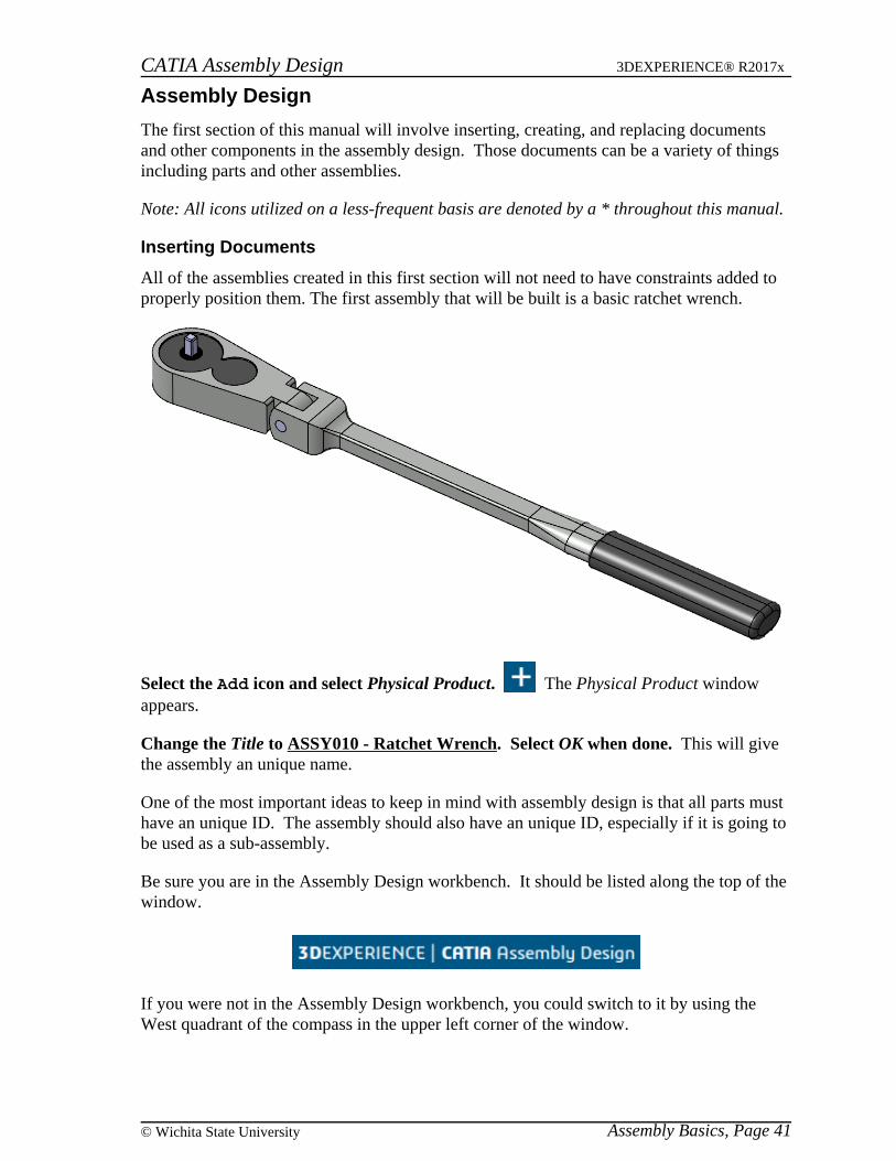
All of the assemblies created in this first section will not need to have constraints added toproperly position them. The first assembly that will be built is a basic ratchet wrench.
Select the Add icon and select Physical Product. The Physical Product windowappears.
Change the Title to ASSY010 - Ratchet Wrench. Select OK when done. This will givethe assembly an unique name.
One of the most important ideas to keep in mind with assembly design is that all parts musthave an unique ID. The assembly should also have an unique ID, especially if it is going tobe used as a sub-assembly.
Be sure you are in the Assembly Design workbench. It should be listed along the top of thewindow.
If you were not in the Assembly Design workbench, you could switch to it by using theWest quadrant of the compass in the upper left corner of the window.
Assembly Basics, Page 41© Wichita State University
CATIA Assembly Design 3DEXPERIENCE® R2017x
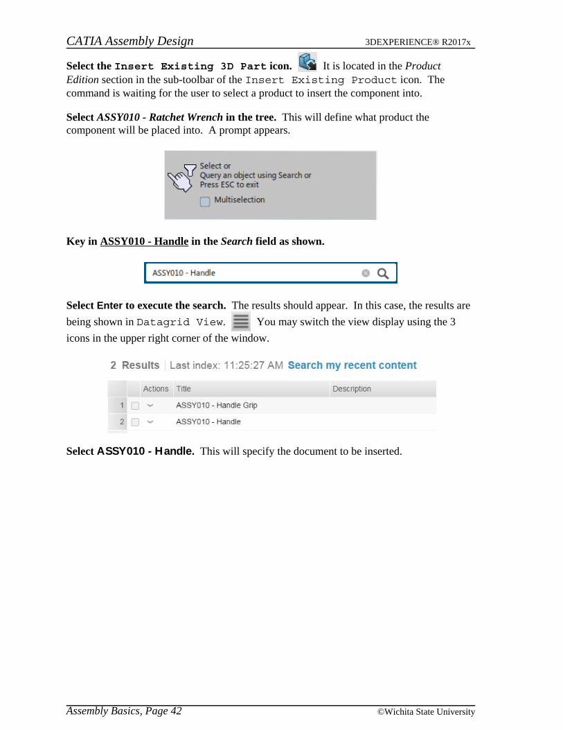
Select the Insert Existing 3D Part icon. It is located in the ProductEdition section in the sub-toolbar of the Insert Existing Product icon. Thecommand is waiting for the user to select a product to insert the component into.
Select ASSY010 - Ratchet Wrench in the tree. This will define what product thecomponent will be placed into. A prompt appears.
Key in ASSY010 - Handle in the Search field as shown.
Select Enter to execute the search. The results should appear. In this case, the results are
being shown in Datagrid View. You may switch the view display using the 3
icons in the upper right corner of the window.
Select ASSY010 - Handle. This will specify the document to be inserted.
Assembly Basics, Page 42 ©Wichita State University

CATIA Assembly Design 3DEXPERIENCE® R2017x
The handle is inserted into the product. Notice the robot is attached to the part, allowing
you to move it within the assembly. The Move To Origin icon is also available.
It is helpful if you move the part using the compass and then decide to move it back to theorigin.
Select in the display to set the part. The robot returns to the lower right hand corner ofthe window.
Press the third mouse button on ASSY010 - Ratchet Wrench and select Insert, Existing3D Part.
Turn on the Multiselection option in the query box as shown. This will allow you toinsert multiple parts at once.
Assembly Basics, Page 43© Wichita State University

CATIA Assembly Design 3DEXPERIENCE® R2017x
Search for ASSY010. This will locate all parts with the ASSY010 prefix. There should be10 results.
Select ASSY010 - Flex Head and ASSY010 - Handle Grip. The query windowshould populate as shown.
Select the Accept All icon to insert them into the assembly. The parts areinserted and pre-positioned as shown.
Sometimes components can be made into a sub-assembly. This can either be donebeforehand, as with the Ratcheting Mechanism that you are going to insert later, or the sub-assemblies can be generated on-the-fly as you will do next.
Assembly Basics, Page 44 ©Wichita State University

CATIA Assembly Design 3DEXPERIENCE® R2017x
Creating a New Product
When you create a new product within an existing product, also known as a sub-product, itis important to understand that this product is a document that will eventually need to besaved. A sub-product or sub-assembly is no different than a product other than the fact it isused within a higher level product.
Right select on ASSY010 - Ratchet Wrench and select Insert, Product. The PhysicalProduct window appears.
Key in ASSY010 - Ratchet Assembly for the Title and select OK. This will insert a newproduct into the assembly. It should appear as shown.
Now that you have a nested product assembly, a product within a product, you need tomake sure that you insert new and existing components into the proper product.
Right select on ASSY010 - Ratchet Assembly.1 and select Insert, Existing Product.
Turn off the Multiselection option in the query box.
Key in ASSY010 in the Search field and select Enter. Select ASSY010 - RatchetingMechanism from the results and select in the display to set the location. This willinsert the subassembly into the product.
Assembly Basics, Page 45© Wichita State University
CATIA Assembly Design 3DEXPERIENCE® R2017x
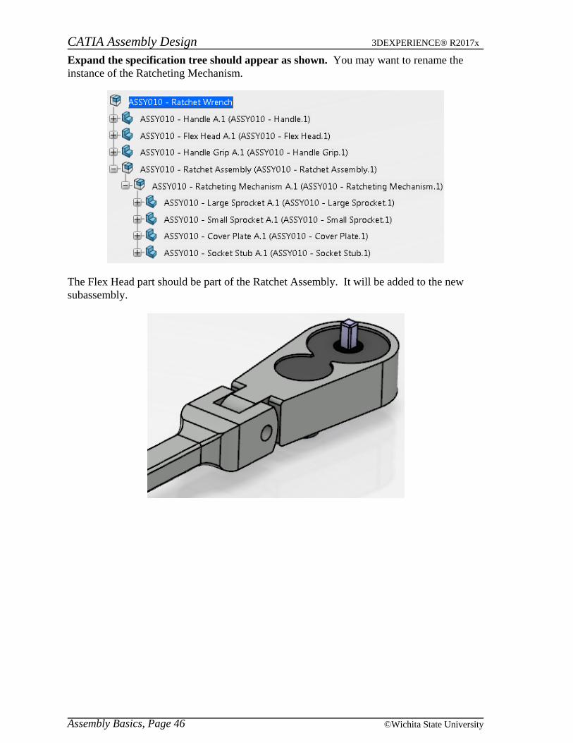
Expand the specification tree should appear as shown. You may want to rename theinstance of the Ratcheting Mechanism.
The Flex Head part should be part of the Ratchet Assembly. It will be added to the newsubassembly.
Assembly Basics, Page 46 ©Wichita State University

CATIA Assembly Design 3DEXPERIENCE® R2017x
Drag the ASSY010 - Flex Head instance onto the ASSY010 - Ratchet Assembly.1product in the specification tree and drop it. It should appear as shown.
This is just another way of inserting parts or products into a subassembly. Dragging anddropping a component is the same as cutting the component and then pasting thecomponent.
Insert a new product into the ASSY010 - Ratchet Wrench and set the Title to beASSY010 - Handle Assembly. The component is created.
Drag both the ASSY010 - Handle and the ASSY010 - Handle Grip into the new product. It should appear as shown.
Double select on the ASSY010 - Handle shape representation as shown. This willactivate the part and switch you into Part Design. The 3d shape representation should havea blue box appear around it in the specification tree.
The blue box signifies the active component within the product structure. Since the Handleis now the active component and it is a part document, you were put into a workbench forparts.
Assembly Basics, Page 47© Wichita State University

CATIA Assembly Design 3DEXPERIENCE® R2017x
Show Geometrical Set.1 in the specification tree. You should see a point appear on thehandle as shown.
The point will be used to locate a new part.
Double select ASSY010 - Ratchet Wrench to make it the active product. A blue boxdoes not always appear around the high level product when it is the active component. Ablue box will always appear around an active component at a lower level.
Assembly Basics, Page 48 ©Wichita State University

CATIA Assembly Design 3DEXPERIENCE® R2017x
Creating a New Part
When you create a new part within the product, it is really no different than when younormally create a new part. It will be a separate document, and can be called upindependent of the main product. When you create a new part you will have the option ofdefining the absolute origin of the part by specifying a location or it will establish itsabsolute origin to coincide with the main product’s absolute origin.
Right select on ASSY010 - Ratchet Wrench and select Insert, 3D Part.
Change the Title to be ASSY010 - Connecting Pin. This will provide a unique name forthe part to be saved into the database.
Select the 3D Shape tab and change the Title to be ASSY010 - Connecting Pin. Thiswill ensure the 3d shape name matches the 3d part name.
Select OK. It should appear as shown in the tree.
Double select on the ASSY010 - Connecting Pin shape representation in thespecification tree. The part is activated and you are switched to Part Design.
Select the Positioned Sketch icon. The Sketch Positioning window appears.
Select the zx plane of the part to define the sketch plane. It may be easiest to select theplane from the tree.
Assembly Basics, Page 49© Wichita State University

CATIA Assembly Design 3DEXPERIENCE® R2017x
In the Origin area, change the drop-down menu to Projection Point and select the pointthat was shown earlier. You may need to turn off the Smart Positioning of theSupport icon in order to use the drop-down menu.
Select OK. You are taken into sketcher.
Create a 0.25 diameter circle at the origin of the sketch. It should appear as shown.
Select the Exit Workbench icon. You are switched back to Part Design.
Be sure the sketch is selected and select the Pad icon. The Pad Definition windowappears.
Key in 0.5 for the Length of the pad, turn on the Mirrored extent option and select OK. The pin is created.
Hide the reference planes of the part. This will clean up the model a little bit.
Assembly Basics, Page 50 ©Wichita State University

CATIA Assembly Design 3DEXPERIENCE® R2017x
Double-select on ASSY010 - Ratchet Wrench to activate the product. The model shouldappear as shown. The pin should be flush on both sides with the handle.
Press the third mouse button on ASSY010 - Ratchet Wrench in the specification treeand select Insert, Existing 3D Part.
Search for the ASSY010 - Hex Socket Large. You will need to key in ASSY010 in thesearch field.
Select the ASSY010 - Hex Socket Large from the results list and then select in thedisplay to set the location. The socket is inserted into the assembly.
Assembly Basics, Page 51© Wichita State University

CATIA Assembly Design 3DEXPERIENCE® R2017x
Creating a New Part from an Existing Part
You will now create a new part from an existing part. You have to be careful when tryingto create a new part from an existing part. If you have instanced the part into the productmultiple times and then you try to change just one of them, they will all change. Thishappens since all of the instances refer to the same 3d shape representation. If you docreate a new part from an existing part you will have to take special care in renaming thepart and instance to use the correct name and then make sure you save it with a differentname. Otherwise you will overwrite the original part.
Double select on the ASSY010 - Hex Socket Large shape representation to activate thepart.
Double select on Sketch.1 in the specification tree and change the diameter constraintto be 0.75in. Exit the sketch. It is located in the PartBody under Pad.1.
Right select on ASSY010 - Hex Socket Large instance in the specification tree andselect Properties. The Properties window appears.
Change the Instance Title to be ASSY010 - Hex Socket Small.1 under the Instance taband the Title to be ASSY010 - Hex Socket Small under the Reference tab. Select OK.
Change the shape representation Title to be ASSY010 - Hex Socket Small as well. Thetree should appear as shown. Make sure you remember to change not only the part numberbut also the instance name to avoid confusion. Now all you have to do is remember to saveit with a different name so that you do not overwrite the original document.
Double select on ASSY010 - Ratchet Wrench to activate the product.
Assembly Basics, Page 52 ©Wichita State University

CATIA Assembly Design 3DEXPERIENCE® R2017x
Save
Save is used to save you work back to the database. This window gives you a graphicalrepresentation of what will be saved and how it will be saved before actually performing thesave operation. The options are covered in detail in Appendix B.
Select the Share icon and select Save with Options. You will have to select theexpansion arrow next to the Save option to get to the additional save options. The Save withOptions window appears.
There are various symbols in the left-hand column. The blue circle with the + means a newobject to be saved to the database. A yellow circle represents a modified object to be saved. An empty circle represents no change to be saved to the database.
Notice the ASSY010 - Connecting Pin shows it is a new part to be saved to the database. This is because you created it from scratch.
Notice the ASSY010 - Hex Socket Small is shown as a modified part. This is because youmodified the Hex Socket Large to create it. You will need to specify you want to save it asa new part and not save over the Hex Socket Large part.
Assembly Basics, Page 53© Wichita State University

CATIA Assembly Design 3DEXPERIENCE® R2017x
Select the ASSY010 - Hex Socket Small part from the window and select the Save As
New icon. The Save as New window appears. This part needs to be saved as
ASSY010 - Hex Socket Small. This will make it a unique new part in the database, so theoriginal Hex Socket Large is not overwritten.
Since you already renamed this part when you modified it, change the Duplicationstring to XXX_ and select OK. The XXX should be your initials. You are returned to theSave with Options window. Notice the part is now designated as a new part.
Select the ASSY010 - Handle from the list. Notice it says it was modified since you unhidthe geometrical set within it. This isn’t your part, so you do not want to save over it.
Select the Exclude icon. It will now be excluded from the save.
Notice the summary on the right side of the window shows what is going to be saved.
Select OK. All the models are saved and a Save successful message appears.
Assembly Basics, Page 54 ©Wichita State University

CATIA Assembly Design 3DEXPERIENCE® R2017x
Constraining and Manipulating Parts Review
This exercise will review the use of the various assembly constraints while introducingsome additional options to improve efficiency.
The first assem
For any parts that are connected together and will not be moving independently, such as thehand grip and the handle, it is usually a good idea to put them into a sub-assembly. The twojaws of the head will move independently of each other, so it is not advisable to put theminto a sub assembly.
Start a new product called ASSY040 - Handle Assembly. You should close all otherdocuments and then start a new product. Make sure you are in the assembly workbenchbefore continuing.
Constraints and Manipulation Review, Page 107© Wichita State University

CATIA Assembly Design 3DEXPERIENCE® R2017x
Insert the ASSY040 - Handle document into the assembly and select in the display toset the position of the part. This can be done the same way you did it in the previoussection.
Insert the ASSY040 - Hand Grip into the assembly. Notice the hand grip and thehandle do not insert into the correct location. This is common unless you build your partswhere they would appear in the assembly.
Create a fix in space constraint on the Handle. The part will not be allowed to move.
Create a coincidence constraint between the center lines of the Handle and the Grip. Set the orientation Preference to be Undefined. You may have to select the insidecylindrical surface of the handle in order to select the center line. The center lines aresnapped together. The grip may be in the wrong orientation.
Constraints and Manipulation Review, Page 108 ©Wichita State University

CATIA Assembly Design 3DEXPERIENCE® R2017x
Select the Engineering Connection icon and select the two faces as shown. You may want to manipulate the models around in order to select the faces.
The Engineering Connection Selection window appears.
Select New connection and select OK. The Engineering Connection Definition windowreappears.
Be sure the Preference is set to be Opposite and select OK.
Constraints and Manipulation Review, Page 109© Wichita State University

CATIA Assembly Design 3DEXPERIENCE® R2017x
The parts are snapped together as shown.
This completes the assembly.
Save and close your assembly. You will reuse your ASSY040 - Handle Assembly tocomplete the ASSY040 - Bolt Cutters assembly.
Constraints and Manipulation Review, Page 110 ©Wichita State University

CATIA Assembly Design 3DEXPERIENCE® R2017x
Start a new product called ASSY040 - Bolt Cutters. Remember, it is always a good ideato give the new part or product a unique, descriptive name right away. Don’t forget to saveyour assembly now and throughout the exercise so if something happens you will not haveto start all over.
Insert your ASSY040 - Handle Assembly twice. Both handle assemblies will beinserted in the same place, so there will only appear to be one inserted. However, if youlook in the specification tree you will see there are two.
Move the second instance of the handle assembly so both are visible. This can be doneby either selecting it in the tree, and dragging one of the box lines of the manipulationbounding box or by using the Manipulation icon.
Select the Engineering Connection icon and select the first instance of thehandle assembly in the tree. The Engineering Connection Definition window
appears.
Change the Type to be Fix in space and select OK. This will fix the assembly in space.
Before continuing, a setting will be changed in order to facilitate better updating of theconnections.
Go to Me , Preferences, Mechanical, Assembly Design and the EngineeringConnection tab. Turn on the By default, automatically position components option asshown.
Select OK. When creating connections, this will allow CATIA to decide which part will bemoved into position. When multiple connections are created, this allows more flexibility inupdating the connections to satisfy all of the constraints.
Constraints and Manipulation Review, Page 111© Wichita State University

CATIA Assembly Design 3DEXPERIENCE® R2017x
At the top of the handle, there is a pivot point that is split in half as shown below. These twofaces are going to be constrained together.
Select the Engineering Connection icon. The Engineering ConnectionDefinition window appears.
Select the two faces as shown above. The two handle assemblies move to get the twofaces in position where they can be in coincidence with one another. You should note thetwo handle assemblies did not align themselves with the centers of the hole. Next, theorientation needs changed so the two faces will be facing each other.
Change the Type to be Coincidence and the orientation Preference to Opposite. Thiswill make the two faces face each other. You can also change the orientation by selectingone of the green arrows on the faces.
Select OK when finished. This may disorientate the two handles dramatically. Not toworry.
You may be wondering why a contact constraint was not used. It would make sense,especially when the two faces are contacting each other. The difference is, a contactconstraint means that the two faces are locked together in the physical world, such as glued,welded, or bolted. That is not the case in this scenario. The two handles need to be free torotate. It does not mean that a contact constraint will not work. Other applications withinCATIA V6 will use the constraints that are applied to perform other analysis andsimulations, and a contact constraint may be confusing. By defining the constraintscorrectly here, the downstream users will not have to re-define them later.
Constraints and Manipulation Review, Page 112 ©Wichita State University

CATIA Assembly Design 3DEXPERIENCE® R2017x
Select the Engineering Connection icon. The Engineering ConnectionDefinition window appears.
Select the centerline at the inside of the pivot hole as shown below. Moving the mousecursor to the inside of the pivot hole will bring up the centerline. Either pivot hole can beselected. It can be difficult to select the centerlines at times, but if there is a curved surfaceavailable to select that is associated with the centerline, you can select on the curved surfaceand it will select the centerline. In this case you may find it easy to select on the curvedsurface of the hole and you will see the centerline appear as you select.
Select the other centerline to align the two pivot holes. The Engineering ConnectionSelection window appears.
Select New connection and select OK. The two handles will snap together. It is verylikely that they are rotated in a way which is invalid for the actual operation of the boltcutters. There are no constraints prohibiting the two handle assemblies from rotatingaround the centerline.
Change the orientation Preference to be Undefined and select OK.
Update the engineering connections. Now it is time to move the two handles with respectto their constraints.
Select the Manipulation icon. This time the two handles are going to be rotatedabout an arbitrary axis.
Select the Drag Around any Axis icon. Now a centerline needs to be selected.
Select the centerline of the two pivots. This will be the same centerline you selectedwhen creating the coincidence constraint.
Constraints and Manipulation Review, Page 113© Wichita State University

CATIA Assembly Design 3DEXPERIENCE® R2017x
Rotate one of the handles around to appear as the picture below. Select OK whendone. This will keep things oriented in a manner that will make it easier to finish buildingthe bolt cutters. You will only be able to rotate ASSY040 - Handle Assembly.2 sinceASSY040 - Handle Assembly.1 is fixed.
This would be a good point to save your document before continuing.
Insert the ASSY040 - Head document into the assembly. Go ahead and move the headto a more suitable location at the top of the handles. You may have to zoom out in order tosee the head.
Constraints and Manipulation Review, Page 114 ©Wichita State University
CATIA Assembly Design 3DEXPERIENCE® R2017x
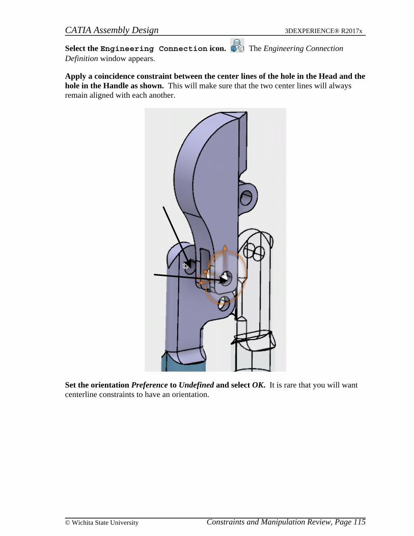
Select the Engineering Connection icon. The Engineering ConnectionDefinition window appears.
Apply a coincidence constraint between the center lines of the hole in the Head and thehole in the Handle as shown. This will make sure that the two center lines will alwaysremain aligned with each another.
Set the orientation Preference to Undefined and select OK. It is rare that you will wantcenterline constraints to have an orientation.
Constraints and Manipulation Review, Page 115© Wichita State University

CATIA Assembly Design 3DEXPERIENCE® R2017x
Apply a coincidence constraint between the two faces that will move the head into theproper location. You will want to create a new connection and make sure the orientationPreference is defined correctly. The end product should appear similar to the one shownbelow.
Update the connections.
Manipulate the head using the manipulation icon to look similar to the diagram shownbelow. This will be the same process as investigated earlier. Make sure you use the rotateabout any axis, and then select the pivot hole for the head.
Insert another ASSY040 - Head into the model.
Constraints and Manipulation Review, Page 116 ©Wichita State University

CATIA Assembly Design 3DEXPERIENCE® R2017x
Add coincidence constraints to the new head and manipulate it so it looks similar tothe diagram shown below. Remember, it is imperative the head be in the right direction. You will want the constraint between the faces to control the orientation with the centerlineconstraint having its orientation undefined.
Select the Engineering Connection icon. The Engineering ConnectionDefinition window appears.
Create a coincidence constraint between the two centerlines shown below.
Constraints and Manipulation Review, Page 117© Wichita State University

CATIA Assembly Design 3DEXPERIENCE® R2017x
Set the orientation Preference to be Undefined and select OK.
Update the connections. The assembly should appear as shown.
Select the Manipulation icon, then select the Drag Around Any Axis option inthe Manipulation Parameters window and ensure the With respect to constraints option
is selected. This will allow the parts to rotate about any given axis that is selected
with respect to any constraints placed on the assembly.
Select the inside of the pivot between the two handles and then select and drag one ofthe handles. You will have to select the handle that is not fixed. Notice the wholeassembly moves. Note, this is not kinematics because the assembly can be moved beyondthe physical limits but this is a good way to test the model to insure the entire assembly isconstrained correctly.
Select OK when finished. This exits the manipulation window.
Next, bolts will be added to complete the assembly.
Insert the ASSY040 - 1.25 Bolt document into the assembly and move it close to thepivot location. This bolt will go in the pivot between the handles.
Constraints and Manipulation Review, Page 118 ©Wichita State University

CATIA Assembly Design 3DEXPERIENCE® R2017x
Add a coincidence constraint between the centerline of the bolt and the centerline ofthe pivot between the handles without any orientation. Remember, this will align thebolt with the hole. Be sure to select OK when you are done.
Add a contact constraint, as a new connection, to put the bolt into the pivot hole. Thiscan be accomplished by adding a contact constraint between the outside of the handle andthe bottom of the bolt head. Your assembly should appear similar to the diagram shownbelow. This time a contact constraint was wanted due to the bolt being tight against one ofthe handles.
The bolt sticks out too far. You need to modify the bolt to be 0.75 inches instead of 1.25inches long, then save it as a separate part. You will do that next.
Expand the 1.25 Bolt branch until you see the PartBody. This will allow you to enter thePart Design workbench through the assembly.
Double select PartBody with the first mouse button. This takes you to the Part Designworkbench allowing you to perform part design tasks. This is similar to what you did whenyou created a new part in the assembly. This time you are going to modify a part.
Constraints and Manipulation Review, Page 119© Wichita State University

CATIA Assembly Design 3DEXPERIENCE® R2017x
Change Pad.1 to have a Length of 0.75 inches. Notice the bolt becomes shorter but thehead of the bolt moves instead of the end of the bolt, this is determined by the originaldesign of the bolt.
Right click on the 1.25 Bolt 3d part branch in the tree as shown below. Since you donot want this new bolt to be referred to as a 1.25 Bolt, you are going to change its namebefore you save the modified part.
Constraints and Manipulation Review, Page 120 ©Wichita State University

CATIA Assembly Design 3DEXPERIENCE® R2017x
Select the Properties option. A Properties window appears similar to the one shownbelow.
Change the Title to be ASSY040 - 0.75 Bolt. On the Instance tab, change the InstanceTitle to be ASSY040 - 0.75 Bolt.1. Select OK when finished.
Change the name of the 3d shape to be ASSY040 - 0.75 Bolt as well. It should appear asshown.
Double select on ASSY040 - Bolt Cutters. This will return you to the main assembly.
Update the connections. The constraints are updated positioning the bolt in the correctlocation. Remember, you used a contact constraint between the bottom face of the bolthead and the outside face of the handles. You can collapse the ASSY040 - 0.75 Bolt branchif you want.
Constraints and Manipulation Review, Page 121© Wichita State University

CATIA Assembly Design 3DEXPERIENCE® R2017x
Select the Share icon and select Save with Options. The Save with Optionswindow appears.
Notice the ASSY040 - 0.75 Bolt is a released part. This is because you created it from the1.25 Bolt. If you wish to save the modified part, you will have to propagate it as a new part.
Select the ASSY040 - 0.75 Bolt and select the Save as New icon. The symbolnext to the part changes to show it will be saved as a new part.
Select OK. The assembly is saved.
Insert the 1.25 Bolt and constrain it to the pivot between the two heads. This is donethe same way as you constrained the previous bolt.
Add two more bolts and constrain them into the proper locations. This will finish theassembly.
Save and close the document.
Constraints and Manipulation Review, Page 122 ©Wichita State University

CATIA Assembly Design 3DEXPERIENCE® R2017x
Assembly Pattern
The assembly pattern option allows you to use an existing pattern within a part to helpposition and constrain components. This is very useful for constraining fasteners topatterns.
Open the ASSY090 - Assembly Pattern product. You should see a couple of casingsattached with a bolt and nut. You will place the rest of the fasteners in the assembly.
Expand the ASSY090 - Casing.1 branch to the PartBody level in order to see thepatterns available. The CircPattern.2 is the one you are going to reuse.
Multiple Instances, Page 144 ©Wichita State University

CATIA Assembly Design 3DEXPERIENCE® R2017x
Select the Assembly Pattern icon. This icon will allow the user to reuse anypattern used in a part design. The Assembly Pattern window appears.
Definition
Component to instantiate The item you are going to use in this pattern
Pattern or set of axes Contains the pattern that is going to be used
Reuse selected instance The original component is used and others are added
Keep Link Updates the number of instances as the pattern ismodified and creates a link back to the pattern
Generated Instances Lists the instances created by the pattern
Select the ASSY090 - Casing Bolt.1 in the tree to define the Component to instantiate.
Select CircPattern.2 from the specification tree to define the Pattern.
Make sure the Reuse selected instance and Keep Link options are on and select OK. Four more instance of the bolt appear in the tree along with Assembly Pattern.1.
Multiple Instances, Page 145© Wichita State University

CATIA Assembly Design 3DEXPERIENCE® R2017x
The bolts should appear in the display as shown.
You should note that the original bolt was used and then four more instances were created.
Double select on the PartBody of Casing.1. This makes that part the active component.
Double select on CircPattern.2 and remove the two instances shown below and selectOK. Just select on the two dots as shown to deactivate the two locations. This will modifythe pattern to have only three holes.
Multiple Instances, Page 146 ©Wichita State University

CATIA Assembly Design 3DEXPERIENCE® R2017x
Double select on the ASSY090 - Assembly Pattern product. This makes the top levelassembly the active component.
Update the assembly. The number of instances of the bolt changes. This is due to the linkto the pattern. The diagram shown below has the product rotated.
Select the Assembly Pattern icon. The Assembly Pattern window appears.
Select the ASSY090 - Casing Nut.1 in the tree to define the Component to instantiate.
Select CircPattern.2 from the specification tree to define the Pattern.
Turn off the Keep Link option and select OK. Two more instances of the nut appear inthe tree, but no assembly pattern operation is created.
Multiple Instances, Page 147© Wichita State University

CATIA Assembly Design 3DEXPERIENCE® R2017x
Modify the CircPattern.2 to turn on the two holes you had deactivated earlier.
Activate the top level product and update the assembly. Notice the assembly pattern forthe bolts updated to add in two additional bolts. However, since the link was not kept forthe nuts, they remain unchanged.
Delete the two nut instances that were added previously and create a new assemblypattern using the ASSY090 - Casing Nut.1 and CircPattern.2. Be sure to turn on theKeep Link option. The model should appear as shown.
Save and close the document.
Multiple Instances, Page 148 ©Wichita State University