Embed Size (px)
Citation preview
Recorder Web View User Manual
Table of Contents:
1. Accessing Via Web Browser
2. Installing the plug
Live View
1. View Page
Introduction
2. PTZPlayback
1. Playback
Picture
1. Picture
Parameters Configuration
1. Local Configuration
2. System
3. Network
4. Video/Audio
5. Image
6. Event
7. Storage
8. Vehicle Detection
9. VCA Configuration
Introduction
Arcdyn, Inc.1370 Tunnel Rd.Asheville, NC 28805

Accessing Via Web Browser
Steps:
1. Open the web browser.
2. In the address field, input the IP address of the network video recorder, e.g., 192.0.0.64, and press the Enter key to enter the
login interface.
3. Select English as the interface language on the topright of login interface.
4. Input the user name and password,and click Login.The default user name is admin, and password is 12345.
5. The dialog box of changing the default password pops up.Click OK to enter the admin interface to change password.
6. Enter the new password and confirm it.Click OK to save the settings.
Note:This product has default user name and password credentials for first time access. You must change these
default credentials to protect against unauthorized access to the product.
Installing the plugin
A popup message appears if you don't have matched plugin installed in your computer. And you are required to install the plug
in before viewing the live view and managing the camera. Please close the web browser and follow the prompts to finish the plug
in installation.
Note: The operations on different web browsers may differ, and the operation on IE8 is taken as an example in the
instructions below.
The live view page allows you to view the realtime video, capture images, realize PTZ control, set/call presets and configure
video parameters.
Descriptions of the Icons on the Live View Page
The functions of the buttons on the toolbar are shown in the following table.
Button Description Button Description
Start All Live View. Stop All Live View.
Live view with the main stream. Live view with the sub stream.
Live view with the transcoded stream. Manually capture the picture.
Manually start all recording. Manually stop all recording.
Audio on and adjust the volume. Mute
Start Twoway Audio
Channel1/Channel2/Channel3.
Stop Twoway Audio
Channel1/Channel2/Channel3.
Enable Digital Zoom. Disable Digital Zoom.
Operating PTZ Control
Purpose:

The added camera must support PTZ function, or a pan/tilt unit has been installed to the camera (with the RS485 parameters
configured) before realizing the PTZ function. PTZ control buttons is used to realize the pan/tilt/zoom movement of the camera.
And the presets settings interface allows you to define a monitor position/point. You can switch the live view to the predefined
monitor position by simply call the preset.
PTZ Control Panel
On the live view page, click to show the PTZ control panel or click to hide it.
Click the direction buttons to control the pan/tilt movements.
Click the zoom/iris/focus buttons to realize lens control.
The description of the icons on the PTZ control panel is shown below.
Button Description
Direction Arrows and Autoscan Button
Zoom /+
Focus /+
Iris +/
Adjust speed of pan/tilt movements
Light On/Off
Wiper On/Off
Auxiliary Focus
Initialize Lens
Enter the menu of camera
Start manual tracking
Start manual tracking
Playback
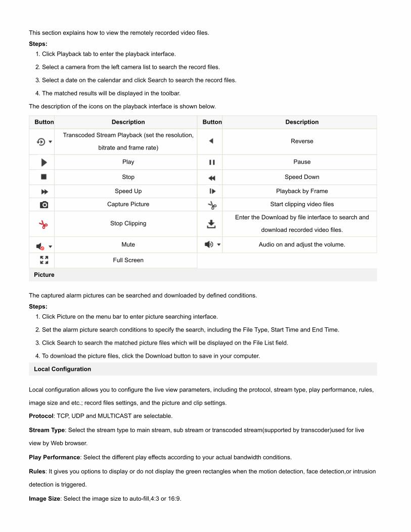
This section explains how to view the remotely recorded video files.
Steps:
1. Click Playback tab to enter the playback interface.
2. Select a camera from the left camera list to search the record files.
3. Select a date on the calendar and click Search to search the record files.
4. The matched results will be displayed in the toolbar.
The description of the icons on the playback interface is shown below.
Button Description Button Description
Transcoded Stream Playback (set the resolution,
bitrate and frame rate)
Reverse
Play Pause
Stop Speed Down
Speed Up Playback by Frame
Capture Picture Start clipping video files
Stop Clipping
Enter the Download by file interface to search and
download recorded video files.
Mute Audio on and adjust the volume.
Full Screen
Picture
The captured alarm pictures can be searched and downloaded by defined conditions.
Steps:
1. Click Picture on the menu bar to enter picture searching interface.
2. Set the alarm picture search conditions to specify the search, including the File Type, Start Time and End Time.
3. Click Search to search the matched picture files which will be displayed on the File List field.
4. To download the picture files, click the Download button to save in your computer.
Local Configuration
Local configuration allows you to configure the live view parameters, including the protocol, stream type, play performance, rules,
image size and etc.; record files settings, and the picture and clip settings.
Protocol: TCP, UDP and MULTICAST are selectable.
Stream Type: Select the stream type to main stream, sub stream or transcoded stream(supported by transcoder)used for live
view by Web browser.
Play Performance: Select the different play effects according to your actual bandwidth conditions.
Rules: It gives you options to display or do not display the green rectangles when the motion detection, face detection,or intrusion
detection is triggered.
Image Size: Select the image size to autofill,4:3 or 16:9.

Auto Start Live View: Enable or disable the autostart of live view once you open the Web browser.
Image Format: Select the saving format of the captured pictures.
The record file settings and the picture and clip settings allow you to select the record file size and the saving path for the
recorded files or captured pictures and clips.
System Configuration
Device Information
The device information interface allows you to check the basic information of the NVR, including the Model, Serial No., Firmware
Version, Encoding Version, Number of Channels, Number of HDDs, Number of Alarm Input and Number of Alarm Output, etc. The
information cannot be changed in this menu. It is the reference for maintenance or modification in future.
Time Settings
Follow the steps below to configure the time synchronization and DST settings.
1. Go to Configuration > System > Time Settings to enter the time settings interface.
2. Select the Time Zone of your location from the dropdown menu.
Time Synchronization by NTP Server
You can check the checkbox to enable the NTP function, and configure the server address, NTP Port, and the Interval, which
is the time interval between the two synchronizing actions with NTP server.
Note: If the camera is connected to a public network, you should use a NTP server that has a time synchronization
function, such as the server at the National Time Center (IP Address: 210.72.145.44). If the camera is set in a
customized network, NTP software can be used to establish a NTP server for time synchronization.
Time Synchronization Manually
Enable the Manual Time Sync function and then click to set the system time from the popup calendar.
Note:You can also check the Sync with computer time checkbox to synchronize the time of the camera with that of
your computer. Define the quota for record and pictures.
3. Click Save to save the settings.
RS485/RS232 Settings
RS485
The RS485 serial port is used to control the PTZ of the connected camera (support the PTZ function). The configuration of the
PTZ parameters should be done before you control the PTZ unit.
By default, the default baud rate is is set as 9600 bps, the Data Bit is 8, the stop bit is 1 and the Parity and Flow Control is None.
RS232
The RS232 port can be used in two ways:
Parameters Configuration: Connect a computer to the device through the serial port. Device parameters can be configured by
using software such as Hyper Terminal. The serial port parameters of PC must be the same as the serial port parameters of the
device.
Transparent Channel: Connect a serial device directly to the DVR/NVR device. The serial device will be controlled remotely by the
computer through the network.
Working Mode
1. Enter the Log interface: Configuration > System > System Settings > Working Mode.
2. Select the working mode to Normal or GB28181.
3. Click Save to save the settings.
Menu Output Mode
1. Enter the Log interface: Configuration > System > System Settings >Menu Output.
2. Select the resolution for the HDMI/VGA1 and HDMI/VGA2 menu output.
3. Click Save to save the settings.
Maintenance
Rebooting the Device
Go to the device reboot interface: Configuration > System > Maintenance, and click Reboot to reboot the device.
Restoring Default Settings
Go to the device restore interface: Configuration > System > Maintenance, and click Restore or Default to restore the default
settings. After restoring the default settings, the IP address is also restored to the default IP address, please be careful for this
action.
Exporting/Importing Configuration Files
Go to the export/import interface: Configuration > System > Maintenance, and click Export to export the current configuration file,
and save it to the certain place.
Click Browse to select the saved configuration file and then click Import to start importing configuration file.
Click Export and set the saving path to save the configuration file in local storage.
Upgrading the System
Go to the upgrade interface: Configuration > System > Maintenance, and click Browse to select the local upgrade file and then
click Upgrade to start remote upgrade.
Log Search
The log search provide you the options to check and export the log files of operation, alarm, and exception information of the
camera. Before you view or export the log information, please make sure the HDD or network disk is connected to the device.
Steps:
1. Enter the Log interface: Configuration > System > Maintenance > Log.
2. Set the log search conditions to specify the search, including the Major Type, Minor Type, Start Time and End Time.
3. Click Search to search log files. The matched log files will be displayed on the Log interface.
4. To export the log files, click Save log to save the log files in your computer.
Camera Management
The main function of the NVR is to connect the network cameras and record the video got from it. So before you can get a live
view or record of the video, you may add the network cameras to the device.
Option 1: Quick Adding of IP Cameras
The NVR provide a function of remote auto searching online IP camera. When there are available IP cameras in the same
network segment of a LAN with NVR, you may add it by one button with default user name, password and port number.
Steps:
1. Click Quick Add to enter the Quick Add interface, and the detected online IP cameras are listed.
2. Select the camera (s) from the list by checking the checkbox(s).
3. Click OK to finish the quick adding of IP cameras.
Option 2: Manually Adding of IP Cameras
Steps:
1. Click Add to enter the Add IP Camera interface.
2. Input the IP address or domain name of the network camera in the IP Camera Address text field, select the protocol, input
the management port and the user name and password, as well as select the transfer protocol.
3. Click OK to finish the adding of IP cameras.
Editing the Connected IP cameras and Configuring Customized Protocols
Editing the Connected IP cameras
After the adding of the IP cameras, the basic information of the camera lists in the page, you can configure the basic setting of the
IP cameras.
Steps:
1. Click the added IP camera to select it and click the Modify button.
2. In the IP camera editing interface, you can edit the IP camera address, protocol and other parameters.
3. Click OK to save the settings and exit the editing interface.
Configuring the customized protocols
To connect the network cameras which are not configured with the standard protocols, you can configure the customized
protocols for them.
Steps:
4. Click the Custom Protocol button in the IP camera management interface to enter the protocol management interface. There
are 16 customized protocols provided in the system, you can edit the protocol name; and choose whether to enable the sub
stream.
5. Choose the stream type to configure in the dropdown list and edit the required parameters.
Protocol Name: Edit the name for the custom protocol.
Enable Stream: For the substream, when the network camera does not support substream or the substream is not
needed, leave the checkbox empty.
Protocol: The network camera adopting custom protocol must support getting stream through standard RTSP.
Transfer Protocol: Select the transfer protocol for the custom protocol.
Port: Set the port No. for the custom protocol.
Stream Path: Set the resource path for the custom protocol. E.g., ch1/main/av_stream.
After adding the customized protocol, the protocol is selectable in the dropdown list of Protocol.
6. Choose the protocols you just added to validate the connection of the network camera.
User Management
The default user of the camera is admin, the password is 12345, and you are highly recommended to change the password
after your first login to guarantee the security. The admin user has permissions to create, modify or delete other accounts. Up
to 31 user accounts can be created.
Steps:
1. Enter User Management interface: Configuration > System > Maintenance > User Management.
2. Click Add to add user.
3. Input the User Name and Password, and confirm the password.
4. Select the Level to Operator or User.
5. You can configure basic permissions by checking the checkbox of corresponding option.
6. Click OK to finish the user addition.
7. You can also select a user account from the list and click Modify to edit the user information or click Delete to remove it
from the list.
Security Service
To enable the remote login, and improve the data communication security, the NVR provides the security service for better
user experience.
Check the checkbox of Enable Telnet to enable the remote login by the telnet, and uncheck the checkbox to disable the
telnet.
Network
TCP/IP
TCP/IP settings must be properly configured before you operate the NVR over network. The NVR supports both the IPv4 and
IPv6. Both versions may be configured simultaneously without conflicting to each other, and at least one IP version should be
configured.
1. Click TCP/IP tab to enter the TCP/IP configuration interface.
2. Two network interfaces are provided by the device. Select Lan1 or Lan2 to configure the network settings.
3. Configure the basic network settings, including the NIC Type, IPv4 or IPv6 Address, IPv4 or IPv6 Subnet Mask, IPv4 or
IPv6 Default Gateway, MTU settings and Multicast Address.
4. Click Save to save the settings.
Port

Port settings allow you to configure the port No. of the HTTP port, RTSP port, HTTPS port, and the server port.
1. Click Port tab to enter the port configuration interface.
2. Set the HTTP port, RTSP port, HTTPS port and server port of the camera.
HTTP Port: The default port number is 80, and it can be changed to any port No. which is not occupied.
RTSP Port:The default port number is 554 and it can be changed to any port No. ranges from 1024 to 65535.
HTTPS Port: HTTPS Port: The default port number is 443, and it can be changed to any port No. which is not occupied.
Server Port: The default server port number is 8000, and it can be changed to any port No. ranges from 2000 to 65535.
3. Click Save to save the settings.
DDNS
DDNS settings allow you to access the device via the dynamic domain name server.
DynDNS
1. Enter Server Address of DynDNS (e.g. members.dyndns.org).
2. In the Domain text field, enter the domain name obtained from the DynDNS website.
3. Enter the User Name and Password registered on the DynDNS website.
4. Click Save to save the settings.
IP Server
1. Enter the Server Address of the IP Server.
2. Click Save to save the settings.
NOIP
1. Choose the DDNS Type as NOIP.
2. Enter the Server Address as www.noip.com.
3. Enter the Domain name you registered.
4. Enter the Port number, if needed.
5. Enter the User Name and Password.
6. Click Save the save the settings, and then you can view the device with the domain name.
PeanutHull
1. Enter the User Name and Password obtained from the PeanutHull website.
2. Click Save the save the setting.
HiDDNS
1. Choose the DDNS Type as HiDDNS.
2. Enter the Server Address www.hikonline.com.
3. Enter the Domain name of the camera. The domain is the same with the device alias in the HiDDNS server.
4. Click Save to save the settings.
PPPoE

If you have no router but only a modem, you can use PointtoPoint Protocol over Ethernet (PPPoE) function.
1. Click PPPoE tab to enter the PPPoE configuration interface.
2. Check the Enable PPPoE checkbox to enable this feature.
3. Enter User Name, Password, and Confirm password for PPPoE access. The user name and password is assigned by
your ISP.
4. Click Save to save the settings.
SNMP
SNMP settings is used to get the device status, parameters and alarm related information and manage the camera remotely
when it is connected to the network.
Before setting the SNMP, please download the SNMP software and manage to receive the device information via SNMP
port. By setting the Trap Address, the NVR can send the alarm event and exception messages to the surveillance center.
1. Click SNMP tab to enter the SNMP configuration interface.
2. Check the corresponding version checkbox to enable the feature.
3. Configure the SNMP settings.The settings of the SNMP software should be the same as the settings you configure
here.
4. Click Save to save the settings.
Email function can be configured to send an email notification to all designated receivers if an alarm event is detected, e.g.,
motion detection event, video loss, video tampering, etc.
Please configure the DNS Server settings under Basic Configuration >Network > TCP/IP or Advanced Configuration
>Network > TCP/IP before using the Email function.
1. Click Email tab to enter the email configuration interface.
2. Configure the required information, including sender, sender's address, SMTP server, SMTP port, SSL, attached image,
interval, authentication. reciever, reciever's address, etc.
3. Click Save to save the settings.
NAT
UPnP™ can permit the device seamlessly discover the presence of other network devices on the network and establish
functional network services for data sharing, communications, etc. If you want to use the UPnP™ function to enable the fast
connection of the device to the WAN via a router, you should configure the UPnP™ parameters of the device.
1. Click NAT tab to enter the configuration interface.
2. Check the checkbox of Enable UPnP™ to enable it.
3. Choose the port mapping mode to Automatic or Manual. When you select Auto, the mapping ports can be automatically
assigned by the router. When you select Manual, you should continue Step4 to edit the mapping ports.

When the Manual mode is selected, configure the HTTP Port (for access by WEB browser), RTSP Port, Server Port and
HTTPS Port respectively.
4. Click Save to save the settings.
Platform Access
The Platform Access settings allow the access to the device by 28181(GB/T28181) platform. Through the access settings,
the device can be registered on the public security platform to realize the live view, playback and other operations.
1. Check the checkbox of Enable to enable the function.
2. Select the access mode to 28181.
3. Configure the SIP and other parameters.
4. Click Save to save the settings.
HTTPS
HTTPS provides authentication of the web site and associated web server that one is communicating with, which protects
against Maninthemiddle attacks.
E.g: If you set the port number as 443 and the IP address is 192.0.0.64, you may access the device by inputting
https://192.0.0.64:443 via the web browser.
1. Enter the HTTPS settings interface.
2. Create the selfsigned certificate or authorized certificate.
3. There will be the certificate information after you successfully create and install the certificate.
4. Click Save to save the settings.
Others
With a remote alarm host configured, the device will send the alarm event or exception message to the host when an alarm
is triggered. The remote alarm host must have the Network Video Surveillance software installed.
1. Enter the Alarm Host IP which refers to the IP address of the remote PC on which the CMS (Client Management
System) software (e.g., iVMS4200) is installed.
2. Enter the Alarm Host IP which must be the same as the alarm monitoring port configured in the software (default port is
7200).
3. Enter the Multicast Address. The multicast can be configured to realize live view for more than the maximum number of
cameras through network. A multicast address spans the ClassD IP range of 224.0.0.0 to 239.255.255.255. It is
recommended to use the IP address ranging from 239.252.0.0 to 239.255.255.255.
4. Click Save to save the settings.
Video and Audio Settings
Video Settings
1. Enter the Video Settings interface: Configuration > Video / Audio > Video.
2. Select the IP camera to select the video settings.

3. Select the Stream Type of the camera to main stream (normal),main stream (event), substream or transcoded stream.
Note: The main stream is usually for recording and live view with good bandwidth, and the substream and third stream
can be used for live view when the bandwidth is limited.
4. Customize the following parameters for the selected main stream or substream:
Video Type: Select the stream type to video stream, or video & audio composite stream. The audio signal will be
recorded only when the Video Type is Video & Audio.
Resolution: Select the resolution of the video output.
Bitrate Type: Select the bitrate type to constant or variable.
Video Quality: When bitrate type is selected as Variable, 6 levels of video quality are selectable.
Frame Rate: Set the frame rate to 1/16~25 fps. The frame rate is to describe the frequency at which the video stream is
updated and it is measured by frames per second (fps). A higher frame rate is advantageous when there is movement in
the video stream, as it maintains image quality throughout.
Max. Bitrate: Set the max. bitrate to 32~16384 Kbps. The higher value corresponds to the higher video quality, but the
higher bandwidth is required.
Video Encoding: If the Stream Type is set to main stream, H.264 and MPEG4 are selectable, and if the stream type is
set to sub stream or third stream, H.264, MJPEG, and MPEG4 are selectable.
5. Click Save to save the settings.
Channelzero Settings
In order to decrease the bandwidth requirement without affecting the image quality, channelzero encoding is supported as
an option for you.
1. Enter the Channelzero settings interface: Configuration > Video/Audio > Channelzero.
2. Check the checkbox to enable the Channelzero Encoding.
3. Select the Max. Bitrate and the Max.Frame Rate.
4. Click Save to save the settings.
Display Settings
You can enter the Display Settings interface to set the brightness, contrast and saturation of the image for the select camera.
Brightness describes bright of the image, which ranges from 0~255, and the default value is 128.
Contrast describes the contrast of the image, which ranges from 0~255, and the default value is 128.
Saturation describes the colorfulness of the image color, which ranges from 0~255, and the default value is 128.
Hue describes the hue of the image color, which ranges from 0~255, and the default value is 128.
OSD Settings
OSD (Onscreen Display) refers to the camera name, time/date format, display mode, and OSD size displayed on the live
view.
Note: The OSD settings must be supported by the connected IP camera.

Steps:
1. Enter the OSD Settings interface: Configuration > Image > OSD Settings.
2. Check the corresponding checkbox to select the display of camera name, date or week if required.
3. Edit the camera name in the text field of Camera Name.
4. Select from the dropdown list to set the time format, date format and display mode.
5. You can use the mouse to click and drag the text frame in the live view window to adjust the OSD position.
6. Click Save to activate above settings.
7. If you want to copy the OSD settings of the current camera to other cameras, click the Copy to button and select the
camera(s) to copy, or click Select All to select all cameras.
Privacy Mask
It enables you to cover certain areas on the live video to prevent certain spots in the surveillance area from being live
viewed and recorded.
Steps:
1. Enter the Privacy Mask Settings interface: Configuration > Image > Privacy Mask.
2. Check the checkbox of Enable Privacy Mask to enable this function.
3. Click Draw Area.
4. Click and drag the mouse in the live video window to draw the mask area.
5. Click Stop Drawing to finish drawing or click Clear All to clear all of the areas you set without saving them.
6. Click Save to save the settings.
Basic Event
Purpose:
Basic event settings refer to the configuration of supported basic events type, including motion detection, video
tampering, alarm input, alarm output, exception, etc.
Motion Detection
Purpose:
It detects the moving objects in the configured surveillance area, and triggers the certain action as a respond to
detection. In order to detect the moving objects accurately and reduce the false alarm rate, normal configuration and
expert configuration are selectable for different motion detection environment.
Normal Configuration
Normal configuration adopts one set of parameter for motion detection during the day and at night.
Task 1: Set the Motion Detection Area.
Steps:
1. Enter the motion detection settings interface: Configuration > Event > Basic Event> Motion Detection.
2. Check the Enable Motion Detection checkbox to enable motion detection.
3. (Optional) You can check the checkbox of Enable Dynamic Analysis for Motion, and then the detected motion objects
are marked with green rectangles on the live video.
Note: To mark the motion objects on the live video, go to Configuration > Local > Live View Parameters and enable
the Rules.
4. Click Draw Area. Click and drag the mouse on the live video to draw a motion detection area.
5. Click Stop Drawing to finish drawing one area.
6. (Optional) Click Clear All to clear all of the areas.
7. (Optional) Move the slider to set the sensitivity of the detection.
Task 2: Set the Arming Schedule for Motion Detection.
Steps:
1. Click Edit to edit the arming schedule.
2. Choose the day you want to set the arming schedule.
3. (Optional) After you set the arming schedule, you can copy the schedule to other days.
4. Click OK to save the settings.
Note: The time of each period can not be overlapped. Up to 8 periods can be configured for each day.
Task 3: Set the Linkage Method for Motion Detection.
Check the checkbox to select the linkage method. Audio warning, notify surveillance center, send email,full screen
monitoring, trigger channel and trigger alarm output are selectable. You can specify the linkage method when an event
occurs.
Audible Warning: Trigger the audible warning locally. And it only supported by the device have the audio output.
Notify Surveillance Center: Send an exception or alarm signal to remote management software when an event occurs.
Send Email: Send an email with alarm information to a user or users when an event occurs.
Full Screen Monitoring: Switch to the full screen playing mode when an event occurs.
Trigger Channel:The video will be recorded when the motion is detected. You have to set the recording schedule first.
Trigger Alarm Output: Trigger one or more external alarm outputs when an event occurs.
Video Tampering
Purpose:
It detects if the image of camera is covered and takes response actions when the alarm is triggered.
Steps:
1. Enter the video tampering settings interface: Configuration > Event > Basic Event> Video Tampering.
2. Check the Enable Video Tampering checkbox to enable the video tampering detection.
3. Set the video tampering area; refer to Task 1 Set the Motion Detection Area in motion detection.
4. Click Edit to edit the arming schedule for video tampering. The arming schedule configuration is the same as the
setting of the arming schedule for motion detection.

5. Check the checkbox to select the linkage method taken for the video tampering. Audible warning, notify surveillance
center, send email and trigger alarm output are selectable.
6. Click Save to save the settings.
Video Loss
Steps:
1. Enter the video Video Loss interface: Configuration > Event > Basic Event> Video Loss.
2. Check the Enable Video Loss Detection checkbox to enable the video loss detection.
3. Click the Arming Schedule to edit the arming schedule for video loss detection. The arming schedule configuration
is the same as the setting of the arming schedule for motion detection. Refer to Step 2 Set the Arming Schedule
for Motion Detection .
4. Check the checkbox to select the linkage method taken for the video loss alarm. Notify surveillance center, send
email and trigger alarm output are selectable. Please Step 3 Set the Alarm Actions for Motion Detection .
5. Click Save to save the settings.
Alarm Input
Purpose:
It detects the alarm input and the alarm output, and take response actions the alarm is triggered.
Steps:
1. Enter the Alarm Input Settings interface:Configuration > Event > Basic Event> Alarm Input.
2. Choose the alarm input No. and the Alarm Type. The alarm type can be NO (Normally Open) and NC (Normally
Closed). Edit the name to set a name for the alarm input (optional).
3. Check the Settings checkbox to set the arming schedule and linkage method.
4. You can also choose the PTZ linking for the alarm input if the added camera is installed with a pan/tilt unit. Check the
relative checkbox and select the No. to enable Preset Calling, Patrol Calling or Pattern Calling.
5. You can copy your settings to other alarm inputs.
6. Click Save to save the settings.
Alarm Output
Steps:
1. Enter the Alarm Output Settings interface: Configuration > Event > Basic Event> Alarm Output.
2. Select one alarm output channel in the Alarm Output dropdown list. You can also set a name for the alarm output
(optional).
3. The Delay time can be set to 5sec, 10sec, 30sec, 1min, 2min, 5min, 10min or Manual. The delay time refers to the
time duration that the alarm output remains in effect after alarm occurs.
4. Click Edit to enter the Edit Schedule Time interface. The time schedule configuration is the same as the settings of the
arming schedule for motion detection.
5. You can copy the settings to other alarm outputs.
6. Click Save to save the settings.
Exception
Purpose:
It detects the exception type of device,including the HDD full, HDD error, network disconnected, IP address
conflicted,illegal login, record/capture exception and hot spare exception.
Steps:
1. Enter the Exception Settings interface: Configuration > Event > Basic Event> Exception.
2. Check the checkbox to set the actions taken for the Exception alarm.
3. Click Save to save the settings.
Smart Event Settings
Purpose:
Smart event settings explain the supported smart events type, including audio exception detection, defocus detection,
scene change detection, face detection, line crossing detection, intrusion detection, etc.
Note: Smart event detection function varies according to different camera models, check the specification for whether the
camera supports the corresponding function.
Audio Exception Detection
Purpose:
Audio exception detection function detects the abnormal sounds in the surveillance scene, such as the sudden increase /
decrease of the sound intensity, and some certain actions can be taken when the alarm is triggered.
Steps:
1. Enter the Audio Exception Detection settings interface: Configuration > Event > Smart Event > Audio Exception
Detection.
2. Check the checkbox of Audio Loss Detection to enable the audio loss detection function.
3. Check the checkbox of Sudden Increase of Sound Intensity Detection to detect the sound steep rise in the
surveillance scene. You can set the detection sensitivity and threshold for sound steep rise.
4. Check the checkbox of Sudden Decrease of Sound Intensity Detectionto detect the sound steep drop in the
surveillance scene. You can set the detection sensitivity and threshold for sound steep drop.
Notes:
Sensitivity: Range [1100], the smaller the value is, the more severe the change should be to trigger the
detection.
Sound Intensity Threshold: Range [1100], it can filter the sound in the environment, the louder the environment
sound, the higher the value should be. You can adjust it according to the real environment.
5. You can view the realtime volume of the sound.
6. Click the Edit button to set the arming schedule.
7. Select the linkage methods for audio exception, including Notify Surveillance Center, Send Email,Full Screen
Monitoring, Trigger Channel for recording and Trigger Alarm Output.
8. Click Save to save the settings.
Defocus Detection
Purpose:
The image blur caused by defocus of the lens can be detected, and some certain actions can be taken when the alarm is
triggered.
Steps:
1. Enter the Dofocus Detection settings interface: Configuration> Advanced Configuration> Smart Event> Defocus
Detection.
2. Check the Enable Defocus Detection checkbox to enable the function.
3. Clickanddrag the slider to set the detection sensitivity. The sensitivity value ranges from 1 to 100, and the higher the
value is, the more easily the defocus image can trigger the alarm.
4. Select the linkage methods for defocus, including Notify Surveillance Center, Send Email,Full Screen
Monitoring,Trigger Alarm Output and Trigger Channel.
5. Click Save to save the settings.
Scene Change Detection
Purpose:
Scene change detection function detects the change of surveillance environment affected by the external factors; such as
the intentional rotation of the camera, and some certain actions can be taken when the alarm is triggered.
Steps:
1. Enter the Scene Change Detection settings interface: Configuration> Event > Smart Event> Scene Change Detection.
2. Check the checkbox of Enable Scene Change Detection to enable the function.
3. Clickanddrag the slider to set the detection sensitivity. The sensitivity value ranges from 1 to 100, and the higher the
value is, the more easily the change of scene can trigger the alarm.
4. Click the Edit button to set the arming schedule.
5. Select the linkage methods for scene change, including Notify Surveillance Center, Send Email, Full Screen
Monitoring, Trigger Channel and Trigger Alarm Output.
6. Click Save to save the settings.
Face Detection
Purpose:

Face detection function detects the face appears in the surveillance scene, and some certain actions can be taken when
the alarm is triggered.
Steps:
1. Enter the Face Detection settings interface: Configuration> Event> Smart Event> Face Detection.
2. Check the checkbox of Enable Face Detection to enable the function.
3. (Optional) You can check the checkbox of Enable Dynamic Analysis for Face Detection, and then the detected face
is marked with green rectangle on the live video.
Note: To mark the detected face on the live video, go to Local Configuration> Live View Parameters and enable the
Rules.
4. Clickanddrag the slider to set the detection sensitivity.
Sensitivity: Range [15]. The higher the value is, the more easily the face can be detected.
5. Click the Edit button to set the arming schedule.
6. Select the linkage methods for face detection, including Notify Surveillance Center, Send Email, Full Screen
Monitoring, Trigger Channel and Trigger Alarm Output.
7. Click Save to save the settings.
Line Crossing Detection
Purpose:
Line crossing detection function detects people, vehicle or other objects which cross a predefined virtual line, and some
certain actions can be taken when the alarm is triggered.
Steps:
1. Enter the Line Crossing Detection settings interface: Configuration> Event > Smart Event> Line Crossing Detection.
2. Check the checkbox of Enable Line Crossing Detection to enable the function.
3. Select the line from the dropdown list for detection settings.
4. Click the Draw Area button,and a virtual line is displayed on the live video.
5. Clickanddrag the line, and you can locate it on the live video as desired. Click on the line, two red squares are
displayed on each end, and you can clickanddrag one of the red squares to define the shape and length of the line.
6. Select the direction for line crossing detection. For example, A>B means only object crossing the line from A side to B
side can be detected.
7. Clickanddrag the slider to set the detection sensitivity.
Sensitivity: The higher the value is, the more easily the line crossing action can be detected.
8. Repeat the above steps to configure other lines. Up to 4 lines can be set. You can click the Clear button to clear all
predefined lines.
9. Click the Edit button to set the arming schedule.
10. Select the linkage methods for line crossing detection, including Notify Surveillance Center, Send Email, Full Screen
Monitoring, Trigger Channel and Trigger Alarm Output.

11. Click Save to save the settings.
Intrusion Detection
Purpose:
Intrusion detection function detects people, vehicle or other objects which enter and loiter in a predefined virtual region,
and some certain actions can be taken when the alarm is triggered.
Steps:
1. Enter the Intrusion Detection settings interface: Configuration> Event > Smart Event> Intrusion Detection.
2. Check the checkbox of Enable Intrusion Detection to enable the function.
3. Select the region from the dropdown list for detection settings.
4. Click the Draw Area button to start the region drawing.
5. Click on the live video to specify the four vertexes of the detection region, and right click to complete drawing.
6. Set the time threshold, detection sensitivity and object percentage for intrusion detection.
Threshold: The threshold for the time of the object loitering in the region. If you set the value as 0, alarm is triggered
immediately after the object entering the region.
Sensitivity: The value of the sensitivity defines the size of the object which can trigger the alarm. When the sensitivity
is high, a very small object can trigger the alarm.
Percentage: Percentage defines the ratio of the inregion part of the object which can trigger the alarm. For example,
if the percentage is set as 50%, when the object enters the region and occupies half of the whole region, the alarm is
triggered.
7. Repeat the above steps to configure other regions. Up to 4 regions can be set. You can click the Clear button to clear
all predefined regions.
8. Click the Edit button to set the arming schedule.
9. Select the linkage methods for intrusion detection, including Notify Surveillance Center, Send Email, Full Screen
Monitoring, Trigger Channel and Trigger Alarm Output.
10. Click Save to save the settings.
Region Entrance Detection
Purpose:
Region entrance detection function detects people, vehicle or other objects which enter a predefined virtual region from
the outside place, and some certain actions can be taken when the alarm is triggered.
Steps:
1. Enter the Region Entrance Detection settings interface: Configuration> Event> Smart Event> Region Entrance
Detection.
2. Check the checkbox of Enable Region Entrance Detection to enable the function.
3. Select the region from the dropdown list for detection settings.
4. Click the Draw Areabutton to start the region drawing.
5. Click on the live video to specify the four vertexes of the detection region, and right click to complete drawing.
6. Clickanddrag the slider to set the detection sensitivity.
Sensitivity: The value of the sensitivity defines the size of the object which can trigger the alarm. When the sensitivity
is high, a very small object entering the region can trigger the alarm.
7. Repeat the above steps to configure other regions. Up to 4 regions can be set. You can click the Clear button to clear
all predefined regions.
8. Click the Edit button to set the arming schedule.
9. Select the linkage methods for region entrance detection, including Notify Surveillance Center, Send Email, Full
Screen Monitoring, Trigger Channel and Trigger Alarm Output.
10. Click Save to save the settings.
Region Exiting Detection
Purpose:
Region exiting detection function detects people, vehicle or other objects which exit from a predefined virtual region, and
some certain actions can be taken when the alarm is triggered.
Steps:
1. Enter the Region Exiting Detection settings interface: Configuration> Event> Smart Event> Region Exiting Detection.
2. Check the checkbox of Enable Region Exiting Detection to enable the function.
3. Select the region from the dropdown list for detection settings.
4. Click the Draw Area button to start the region drawing.
5. Click on the live video to specify the four vertexes of the detection region, and right click to complete drawing.
6. Clickanddrag the slider to set the detection sensitivity.
Sensitivity: The value of the sensitivity defines the size of the object which can trigger the alarm. When the sensitivity
is high, a very small object exiting from the region can trigger the alarm.
7. Repeat the above steps to configure other regions. Up to 4 regions can be set. You can click the Clear button to clear
all predefined regions.
8. Click the Edit button to set the arming schedule.
9. Select the linkage methods for region exiting detection, including Notify Surveillance Center, Send Email, Full Screen
Monitoring, Trigger Channel and Trigger Alarm Output.
10. Click Save to save the settings.
Loitering Detection
Purpose:
Loitering detection function detects people, vehicle or other objects which loiter in a predefined virtual region for some
certain time, and a series of actions can be taken when the alarm is triggered.
Steps:
1. Enter the Loitering Detection settings interface: Configuration> Event> Smart Event> Loitering Detection.
2. Check the checkbox of Enable Loitering Detection to enable the function.
3. Select the region from the dropdown list for detection settings.
4. Click the Draw Area button to start the region drawing.
5. Click on the live video to specify the four vertexes of the detection region, and right click to complete drawing.
6. Set the time threshold and detection sensitivity for loitering detection.
Threshold: The threshold for the time of the object loitering in the region. If you set the value as 5, alarm is triggered
after the object loitering in the region for 5s; If you set the value as 0, alarm is triggered immediately after the object
entering the region.
Sensitivity: The value of the sensitivity defines the size of the object which can trigger the alarm. When the sensitivity
is high, a very small object loitering in the region can trigger the alarm.
7. Repeat the above steps to configure other regions. Up to 4 regions can be set. You can click the Clear button to clear
all predefined regions.
8. Click the Edit button to set the arming schedule.
9. Select the linkage methods for loitering detection, including Notify Surveillance Center, Send Email, Full Screen
Monitoring, Trigger Channel and Trigger Alarm Output.
10. Click Save to save the settings.
People Gathering Detection
Purpose:
People gathering detection alarm is triggered when people gather around in a predefined virtual region, and a series of
actions can be taken when the alarm is triggered.
Steps:
1. Enter the People Gathering Detection settings interface: Configuration> Event> Smart Event> People Gathering
Detection.
2. Check the checkbox of Enable People Gathering Detection to enable the function.
3. Select the region from the dropdown list for detection settings.
4. Click the Draw Area button to start the region drawing.
5. Click on the live video to specify the four vertexes of the detection region, and right click to complete drawing.
6. Set the object percentage for people gathering detection.
Percentage: Percentage defines the gathering density of the people in the region. Usually, when the percentage is
small, gathering of not so many people can trigger the alarm.
7. Repeat the above steps to configure other regions. Up to 4 regions can be set. You can click the Clear button to clear
all predefined regions.
8. Click the Edit button to set the arming schedule.

9. Select the linkage methods for people gathering detection, including Notify Surveillance Center, Send Email, Full
Screen Monitoring, Trigger Channel and Trigger Alarm Output.
10. Click Save to save the settings.
Fast Moving Detection
Purpose:
Fast moving detection alarm is triggered when people, vehicle or other objects move fast in a predefined virtual region,
and a series of actions can be taken when the alarm is triggered.
Steps:
1. Enter the Fast Moving Detection settings interface: Configuration> Event > Smart Event> Fast Moving Detection.
2. Check the checkbox of Enable Fast Moving Detection to enable the function.
3. Select the region from the dropdown list for detection settings.
4. Click the Draw Area button to start the region drawing.
5. Click on the live video to specify the four vertexes of the detection region, and right click to complete drawing.
6. Clickanddrag the slider to set the detection sensitivity.
Sensitivity: The value of the sensitivity defines the moving speed of the object which can trigger the alarm. The
higher the value is, the more easily a moving object can trigger the alarm.
7. Repeat the above steps to configure other regions. Up to 4 regions can be set. You can click the Clear button to clear
all predefined regions.
8. Click the Edit button to set the arming schedule.
9. Select the linkage methods for fast moving detection, including Notify Surveillance Center, Send Email, Full Screen
Monitoring, Trigger Channel and Trigger Alarm Output.
10. Click Save to save the settings.
Parking Detection
Purpose:
Parking detection function detects illegal parking in places such as highway, oneway street, etc., and a series of actions
can be taken when the alarm is triggered.
Steps:
1. Enter the Parking Detection settings interface: Configuration> Event> Smart Event> Parking Detection.
2. Check the checkbox of Enable Parking Detection to enable the function.
3. Select the region from the dropdown list for detection settings.
4. Click the Draw Area button to start the region drawing.
5. Click on the live video to specify the four vertexes of the detection region, and right click to complete drawing.
6. Set the time threshold and detection sensitivity for parking detection.

Threshold: The threshold for the time of the vehicle parking in the region. If you set the value as 10, alarm is triggered
after the vehicle stay in the region for 10s.
Sensitivity: The value of the sensitivity defines the size of the vehicle which can trigger the alarm. When the
sensitivity is high, a vehicle of small size can trigger the alarm.
7. Repeat the above steps to configure other regions. Up to 4 regions can be set. You can click the Clear button to clear
all predefined regions.
8. Click the Edit button to set the arming schedule.
9. Select the linkage methods for parking detection, including Notify Surveillance Center, Send Email, Full Screen
Monitoring, Trigger Channel and Trigger Alarm Output.
10. Click Save to save the settings.
Unattended Baggage Detection
Purpose:
Unattended baggage detection function detects the objects left over in the predefined region such as the baggage,
purse, dangerous materials, etc., and a series of actions can be taken when the alarm is triggered.
Steps:
1. Enter the Unattended Baggage Detection settings interface: Configuration> Event> Smart Event> Unattended
Baggage Detection.
2. Check the checkbox of Enable Unattended Baggage Detection to enable the function.
3. Select the region from the dropdown list for detection settings.
4. Click the Draw Area button to start the region drawing.
5. Click on the live video to specify the four vertexes of the detection region, and right click to complete drawing.
6. Set the time threshold and detection sensitivity for unattended baggage detection.
Threshold: The threshold for the time of the objects left over in the region. If you set the value as 10, alarm is
triggered after the object is left and stay in the region for 10s.
Sensitivity: The value of the sensitivity defines the similarity degree of the background image. Usually, when the
sensitivity is high, a very small object left in the region can trigger the alarm.
7. Repeat the above steps to configure other regions. Up to 4 regions can be set. You can click the Clear button to clear
all predefined regions.
8. Click the Edit button to set the arming schedule.
9. Select the linkage methods for unattended baggage detection, including Notify Surveillance Center, Send Email, Full
Screen Monitoring, Trigger Channel and Trigger Alarm Output.
10. Click Save to save the settings.
Object Removal Detection
Purpose:

Object removal detection function detects the objects removed from the predefined region, such as the exhibits on
display, and a series of actions can be taken when the alarm is triggered.
Steps:
1. Enter the Object Removal Detection settings interface: Configuration> Event> Smart Event> Object Removal
Detection.
2. Check the checkbox of Enable Object Removal Detection to enable the function.
3. Select the region from the dropdown list for detection settings.
4. Click the Draw Area button to start the region drawing.
5. Click on the live video to specify the four vertexes of the detection region, and right click to complete drawing.
6. Set the time threshold and detection sensitivity for object removal detection.
Threshold: The threshold for the time of the objects removed from the region. If you set the value as 10, alarm is
triggered after the object disappears from the region for 10s.
Sensitivity: The value of the sensitivity defines the similarity degree of the background image. Usually, when the
sensitivity is high, a very small object taken from the region can trigger the alarm.
7. Repeat the above steps to configure other regions. Up to 4 regions can be set. You can click the Clear button to clear
all predefined regions.
8. Click the Edit button to set the arming schedule.
9. Select the linkage methods for object removal detection, including Notify Surveillance Center, Send Email, Full Screen
Monitoring, Trigger Channel and Trigger Alarm Output.
10. Click Save to save the settings.
Storage Settings
Storage management allows you to view the HDD status, including the capacity, free space, status, type, and progress,
etc., and format the HDD if it is required. Also you can assign the quota for pictures and record files.
Record Schedule
1. Enter the Record Schedule interface: Configuration > Storage > Schedule Settings > Record Schedule.
2. Check the checkbox of Enable to enable the record schedule settings.
3. Edit the record schedule.
4. Choose recording time period and record type.
5. You can click the Advanced button to set the audio record, ANR, prerecord, postrecord, and overwrite,stream type,
expired time,etc.
6. Click OK to save the settings.
Storage Management
Storage management allows you to view the HDD status, including the capacity, free space, status, type, and progress,
etc., and format the HDD if it is required. Also you can assign the quota for pictures and record files.

Net HDD Management
Normally, two storage methods are selectable, which are NAS (NetworkAttached Storage) and IP SAN.
1. Go to Configuration >Storage > Storage Management > NetHDD to get the NetHDD properly configured before storing
the record files, capture pictures, and log files in it.
2. Enter the IP address of the network disk, and enter the file path to add a NAS or IP SAN.
3. If the status of the disk is Uninitialized,go to the HDD Management interface to check the corresponding checkbox to
select the disk and click Format to start initializing the disk.
4. Click Save to save the settings.
HDD Detection
S.M.A.R.T Settings
The device provides the HDD detection function such as the adopting of the S.M.A.R.T. and the Bad Sector Detection
technique. The S.M.A.R.T. (SelfMonitoring, Analysis and Reporting Technology) is a monitoring system for HDD to detect
and report on various indicators of reliability in the hopes of anticipating failures.
1. Go to Configuration >Storage > Storage Management > HDD Detection to enter the HDD detection interface.
2. Select the S.M.A.R.T.Settings tab.
3. Select the HDD to perform the selftest.
4. Select the selftest type to Short Test, Expanded Test or Conveyance Test(testing the data transmission performance of
the disk).
5. Click the Start Selftest button to start S.M.A.R.T for the selected HDD. And the related information of the S.M.A.R.T. is
shown on the list below.
Note:If you want to use the HDD even when the S.M.A.R.T.checking is failed, you can check the checkbox of the
Continue to use the disk when selfevaluation is failed item.
6. Click Save to save the settings.
Bad Sector Detection
1. Go to Configuration >Storage > Storage Management > HDD Detection to enter the HDD detection interface.
2. Select the Bad Sector Detection tab.
3. Select the HDD No. in the dropdown list to configure, and choose Full Detection or Key Area Detection as the detection
type.
4. Click the Start detect button to start bad sector detection for the selected disk. And you can also click Pause/Resume or
Cancel the process during the detecting process.
5. You can view the detecting results and information are displayed on the interface.
Capture Settings
You can configure the scheduled and eventtriggered capture. The captured picture can be stored in the HDD, NetHDD or
the SD card (if supported by the camera).

1. Enter the Capture Settings interface: Configuration > Storage > Schedule Settings > Capture.
2. Check the Enable checkbox to enable the capture schedule settings.
3. Edit the capture schedule.
4. Click the Capture Parameters to configure the format,resolution,quality of captured pictures and the capture interval for
the the continuous and eventtriggered capturing mode respectively.
5. Click Save to save the settings.
Holiday
1. Enter Holiday Settings interface: Configuration > Storage > Advanced Settings > Holiday
2. Select a holiday item from the list and click Edit icon to enter the parameters settings interface.
3. Edit the corresponding parameters, including Holiday Name, Type, Start Date and End Date.
4. Click OK to save and exit the settings.
Other Advanced Settings
You can click Configuration > Storage > Advanced Settings > Advanced to enable the HDD sleeping and overwriting,
and set the packet time of recorded files.
VCA Information
Select the VCA resource type to Behavior Analysis, Behavior Analysis + Face Capture.Only one VCA type can be operated
each time.
Overlay & Picture
Version information lists the version of the VCA events.
Display information includes the display of VCA information on the picture and on the stream.
Display Target info. on Alarm Picture: There will be a frame on the up loaded alarm picture if the checkbox is checked.
Display Rule info. on Alarm Picture: The captured target and the configured area will be framed on the alarm picture.
Display VCA info. on Stream: The green frames will be displayed on the target if in a live view or playback.
Snapshot Setting: You can set the quality and resolution for the captured picture.
Picture Quality: Good, better, and best are selectable.
Picture Quality:Picture Resolution: CIF, 4CIF, 720P, and 1080P are selectable.
Advanced Configuration
Behavior Analysis
Draw the Shield Region
Steps:
You can set the shield region in which all the VCA rules are invalid.
Click the Shield Region tab to enter the shield region configuration interface

Click the icon, and left click endpoints in the live view window and right click to finish the area drawing.Polygon
area with up to 10 sides is supported.
Click Save to save the settings.
Note: If live view is stopped, it is unable to draw the shield regions.
Configure the Scene Parameters
Steps:
1. Click the Scene Parameters tab to enter the scene settings interface.
2. Click the Scene Name filed and edit a name for the scene.
3. Click Call to call the preset to the desired position and click Save to save the settings.
4. Check the checkbox of Track to enable the auto tracking function and set the tracking duration time.
5. Check the checkbox of Limited Tracking and set up/down and left/right limit stops of autotracking by clicking Call to
call the corresponding preset position.
6. Click Save to save the settings.
Configure the Rules
Steps:
1. Click the Rule tab to enter the rule settings interface.
2. Check the checkbox of Rule to enable rules of behavior analysis.
3. Select the rule type.
4. Select Filter type. Pixels and Actual Size are selectable, and set the duration.
5. Draw areas.
6. Click Save to save the settings.
7. Click Arming Schedule tab, click Edit to set the schedule time for each rule, and click Save to save the settings.
8. Click Alarm Linkage tab, check the checkbox of corresponding linkage method for each rule, and click Save to save the
settings.