Embed Size (px)
Citation preview

Surgical Technique


33
Table of conTenTs
design characteristics............................................................................................4
system overview..........................................................................................................5
preoperative planning.............................................................................................6
surgical technique....................................................................................................6
implants........................................................................................................................17
instruments................................................................................................................21
nota bene: the described surgical technique is the suggested treatment for the uncomplicated procedure. in the final analysis the preferred treatment is that which addresses the needs of the individual patient.
copyright note: acs®, aida®, cepthar®, dialoc®, ecoFit®, load shiFt®, implaFix®, implavit® and implatan® are registered trademarks of implantcast GmbH. The use and copy of the content of this brochure are only allowed with prior permit given by the implantcast GmbH.

44
Pole-area: gap between cup and acetabulum protection of the bone
fit-area: reduction of tension towards the pole area
Pressfit-area: safety against tilting and migration
The ‚Low Profile’ design of the cementless ecoFit® acetabular system is defined to enhance the stability and to support long-lasting bony integration.
Pole-areaThe PressFit of hemispherical acetabular implants results from under-reaming of the implant bed. The resulting PressFit acts upon the total bony area of contact. In the area of the acetabular base and in the pole area respectively this action is undesirable, because the resulting forces hold the risk of migration and loosening of the implant. For this reason the ecoFit® cup is flattened in order to guarantee the protection of the bone and to reduce the risk of loosening.
Pressfit-areathe ecoFit® cup locks stable through a peripheral enhanced PressFit. The primary stability is produced by the rough pure titanium coating. The PressFit grows progressively with the external diameter of the ecoFit® acetabular implants. The primary stability decisively depends on the rate of tensions which appear during insertion of the implant. The degrees of these bone tensions are defined by the rate of the under-reaming. On equal under-reaming with all implant diameters you can see an increase of the resulting bone tensions rising with the growing diameter of the cups. To prevent bursts of the acetabulum with large diameters and decrease of the primary stability with small implants, the pressFit of ecoFit® increases proportionally to the cup diameter (from 1,6mm with external diameter: 46mm up to 2,05 with external diameter: 68 mm).
fit areathe cup has also got a rough pure titanium coating in the adjacent Fit area in order to enhance the osteointegration. The geometry corresponding to the reaming of the cup leads to reduced ten-sions in direction to the pole.
1) Literature: Vergleichende Analyse der Primärstabilität des neues Oberflächendesigns EcoFit - Sellenschloh; Morlock - TUHH
design characTerisTics

55
sysTem overview
In order to minimize the micro motions and prevent PE abrasion in the contact area between metal cup and PE insert, a special locking mechanism has been developed. It allows the use of the identical acetabular cup implant for the use of Biolox® delta ceramic or pe inserts. the pe inserts are sterilized with ethylene oxide gas to prevent oxidative predegradation of the mate-rial. Alternatively PE inserts made of implacross® crosslinked polyethylene, are available. These PE-inserts have shown improved wear characteristics during preclinical tests. Furthermore the accis® inserts (ceramic coated metal-on-metal) can be used in conjunction with special ACCIS® heads.
the implants of the ecoFit® system show a central hole in the acetabular base. The hole allows the control of the seating and the attachment of the impactor. It is covered by the use of a central screw cover which captures the cover while inserting. The EcoFit® cup has three covered screw holes. To enhance the primary stability by using screws, the tapered covers may be removed (while the cup is already seated) and screws will be used. The cancellous screws can be angled up to 15°. The cup is also available without three additional holes (EcoFit® NH). Furthermore both options can be ordered with additinal implaFix® HA-coating.

66
surgical Technique
To prepare the acetabular bone (fig. 1), reamers of external diameters in increments of 2mm are available.
Align the reamer anatomically, in abduction of about 45° and anteversion of 20 - 30°. By using the reamer the acetabulum is prepared until bleeding subchondral bone is reached (fig. 2).
please note that the posterior and anterior acetabular rim serve for sizing and therefore should be preserved accordingly. figure 2
figure 1
PreoPeraTive Planning
The preoperative planning is raised on the ba-sis of the X-rays of the affected hip and the con-tralateral hip.regarding the choice of the cup size and position the ecoFit® cup should rest congruently against the subchondral bone.
PreParaTion of The aceTabulum
Please expose the hip joint completely.resect the articular capsule and the labrum ac-etabulare. Dissect the bony rim of the acetabu-lum, if possible, completely. Remove the osteophytes and the connective tissue of the fossa acetabuli. in order to rebuild normal anatomical proportions, the acetabulum should be medialised to the extent to which you are able to reconstruct the preoperatively cho-sen centre of rotation.

77
sizing
using the trial shells, the size of the prepared implant bed is checked (fig. 3a).
The slots of the trial shells serve for the deter-mination of the bone contact between the re-spective trial shell and the prepared acetabulum (fig. 3b).
please consider that the trial shells are of a hemispherical shape, while the EcoFit® cup shows a circumferential enhanced PressFit.
figure 3a
figure 3b

88
insertion of the cup
the chosen ecoFit® cup is combined with the universal impactor and inserted in the prepared acetabulum (fig. 4). Exactly aligned the EcoFit® cup should rest at an angle of abduction of 45° and an anteversion of 10-20°.
the chosen size of the ecoFit® cup should have the same diameter as the previously used rea-mer. the pressFit of the ecoFit® cup increases proportionally to the cup diameter.
The stability of the implant fit (PressFit) and the implant-to-bone contact can be adjusted by moving the impactor at the end of the handle. In doing so the whole pelvic should move without changing the position of the cup in the acetabu-lum. If the stability is not desirable, please con-sider to use a larger reamer and cup size or con-sider to use additional cancelous bone screws to enhance the stabilty (see page 14).
If so, you can act on the assumption of a firm primary fit and the impactor can be removed. Peripheral osteophytes that possibly hinder the femoral implant from its full range of motion have to be removed (fig. 5).
figure 4
figure 5

99
insertion of the central cover
the central hole of the ecoFit® cup has got a thread and is closed with a screw driver. The captured screw driver holds the cover while in-serting (fig. 6 and fig. 7)
Before inserting the central screw holder, the central hole has to be cleaned thoroughly by rinsing and sucking off.
Make sure that the central cover is seated com-pletely (fig. 8).
figure 7
figure 6
figure 8

1010
Trial reduction
when the ecoFit® cup is fixed firmly in the de-sired position, a trial insert of the appropriated size may be inserted for the trial reduction.
By the use of the trial insert you avoid damages of the PE and the ceramic insert respectively.
The table below shows the colour coding of the trial inserts. the same colour coding could be found on the outside labelling of the implant packages.
Combine the universal impactor with the trial im-pactor of the correct size and colour (see table 1) and insert the trial insert (fig. 9).
cup Ø 46-48mm
cup Ø 60-68mm
cup Ø 56-58mm
cup Ø 50-54mm
head
Ø 28mm
head
Ø 32mm
head
Ø 32mm
head
Ø 36mm
head
Ø 32mm
head
Ø 36mm
head
Ø 32mm
head
Ø36mm
Table 1
figure 9

1111
removal of the trial insert
Mount the trial insert extractor to the universal impactor.
insert the tip of the extractor into the bottom hole of the trial insert (fig.10) and turn the extractor. It will hook in and the trial insert can be pulled out (fig. 11).
figure 10
figure 11

1212
insertion of the Pe-insert
Before final insertion of the PE articulation in-serts into the ecoFit® cup, the rim and the inner surface have to be cleaned thoroughly. Tissue and bone particles have to be removed.
Combine the impactor for PE insert 10° with the PE insert of the correct size. The two spikes of the impactor will seat firmly into the holes of the PE insert. Before pressing in the PE insert 10° make sure the overhang is placed in the apropri-ated position. Please respect that the X-mark of the impactor should line up with the mark of the acetabular cup (fig. 12).The overhang optimizes the stability of the joint and reduces the tendency to subluxate. Usually the overhang is inserted in the cranio/posterior direction.
The PE insert 0° is inserted by using the non captured impactor as it is used for inserting the ceramic inserts (see next page).
Please make sure that the PE insert fits with sta-bility thus assuring that the snap mechanism of the PE insert is caught completely by the cup (fig. 13).
If a removal of the PE insert from the EcoFit®
cup is necessary for correction, the polyethylene component has to be lifted up and discarded.In no case the PE insert may be inserted into the cup a second time. The use of a new PE insert is mandatory.
figure 12
figure 13

1313
insertion of the ceramic, metalic® or accis® insert
Before final insertion of one of the three insert types into the EcoFit® cup the rim and the in-ner surface of the cup have to be cleaned thor-oughly. Tissue and bone particles have to be removed. The following pictures are explaining the technique showing the Biolox® delta insert. metalic® and accis® inserts are inserted in the same way.
after a positioner for ceramic of the appropriated diameter had been mounted to the universal im-pactor, the insert is inserted into the cup (fig. 14).
The insert is conically locked into the EcoFit® cup (fig. 15a). If a ceramic insert has to be removed in case of revision, only a PE insert may be in-serted in the residual cup implant afterwards.Make sure that the insert is fully seated (fig. 15b) before final reduction of the joint is performed (fig. 16).
figure 14
figure 15a
figure 15b
figure 16

1414
application of screws
The stability of the primary fixation of the cup can be enhanced by the use of additional cancellous bone screws.
The screw holes are covered, so please remove the plug of the desirable screw hole or holes (fig 17a). Therefore use the special plug remover. Attach the tip of the remover to the plug. The clamps should be inserted into the plug (fig. 17b) and then turned a little bit until a stable connec-tion is reached.
Please unlock the plug by a slightly bending of the remover (fig. 17c). The plug is captured by the tip of the remover and it can be pulled out (fig. 18).
figure 18
figure 17c
figure 17a
figure 17b

1515
application of screws
When you position the holes, please consider that the most suitable bone for screw fixation is situated in the cranio/posterior parts of the acetabulum, whereas a screw fixation in the os ischii or os pubis leads to an unsatisfactory fit of the screws. In case of inserting the cancellous bone screws in direction to the foramen ischiadicum, you may guard against an injury of the N. ischiadicus by an exact palpation of this part.
When positioning the screws and drilling the holes, please act with utmost caution to avoid the penetration of the interior corticalis of the pel-vis or the foramen ischiadicum. Please consider the run of the neurovascular structures.
For every chosen hole pilot holes are to be drilled. Because of the risk of artery injuries do not drill directly in anterior or medial direction. Please use the angled drill guide to pre-drill the screw holes. Screws can be angled up to 15 de-grees.
Mount a drill bit (lengths: 56mm or 70mm) to the flexible drill shaft and drill through the drill guide (fig. 19).
Before inserting the cancellous bone screws the exact length of the screw is determined by using the special depth gauge. the length has to be determined exactly in order to avoid injuries of the soft tissue in the interior of the pelvis. Please insert the depth gauge and measure the length of the screw (fig. 20). You can read the correct length from the handle of the depth gauge when the flexible measuring needle is seated correctly.
figure 19
figure 20

1616
application of screws
Please select the screw of the previously deter-mined length. Use the cardan screw driver to lock the screws (fig. 21).
make sure that the head of the cancellous bone screw is completely counter-sunk into the hole of the ecoFit® cup to assure the correct positioning of the pe and ceramic insert.
The stability of the implant fit is checked by ex-ercising pressure to the rim of the cup. this sta-bility test must not show any visible motion of the ecoFit® cup. If the primary stability is still un-certain, an additional fixation of the screw or the use of a cemented acetabular component shall be considered.
figure 21
figure 22
figure 23

1717
imPlanTsecofit® cup, cementless
implatan®, tial6v4 acc. to DIN ISO 5832/3 with implaFix® cpTi coating acc. to DIN ISO 5832/2
ecofit® nh cup, cementlessimplatan®, tial6v4 acc. to DIN ISO 5832/3 with implaFix® cpTi coating acc. to DIN ISO 5832/2
and ha coating
spongiosa screw flat head Ø 6,5mmimplatan®, tial6v4 acc. to DIN ISO 5832/3
ref length0280-1015 15mm0280-1020 20mm0280-1025 25mm0280-1030 30mm0280-1035 35mm0280-1040 40mm0280-1045 45mm
ref standard größe ref nh-version0220-0046 46mm 0220-01460220-0048 48mm 0220-01480220-0050 50mm 0220-01500220-0052 52mm 0220-01520220-0054 54mm 0220-01540220-0056 56mm 0220-01560220-0058 58mm 0220-01580220-0060 60mm 0220-01600220-0062 62mm 0220-01620220-0064 64mm 0220-01640220-0066 66mm 0220-01660220-0068 68mm 0220-0168
ref standard größe ref nh-version0220-0346 46mm 0220-04460220-0348 48mm 0220-04480220-0350 50mm 0220-04500220-0352 52mm 0220-04520220-0354 54mm 0220-04540220-0356 56mm 0220-04560220-0358 58mm 0220-04580220-0360 60mm 0220-04600220-0362 62mm 0220-04620220-0364 64mm 0220-04640220-0366 66mm 0220-04660220-0368 68mm 0220-0468

1818
imPlanTs
ceramic cup insertBioloX® delta ceramic al2o3 and Zro2
ref size0220-3239 insert 32/39 (46-48mm)0220-3244 insert 32/44 (50-54mm)0220-3644 insert 36/44 (50-54mm)0220-3248 insert 32/48 (56-58mm)0220-3648 insert 36/48 (56-58mm)0220-3252 insert 32/52 (60-68mm)0220-3652 insert 36/52 (60-68mm)
accis®-cup insertimplavit® acc. to DIN ISO 5832/4
the accis®-inserts may be inserted only in combination with ACCIS®-heads.
ref größe0221-3239 insert 32/39 (46-48mm)0221-3644 insert 36/44 (50-54mm)0221-3648 insert 36/48 (56-58mm)0221-3652 insert 36/52 (60-68mm)0221-4048 insert 40/48 (56-58mm)0221-4452 insert 44/52 (60-68mm)

1919
imPlanTsPe cup insert 0°
UHMW-PE acc. to DIN ISO 5834/2ref size
0280-2039 insert 28/39 (46-48mm)0280-3444 insert 32/44 (50-54mm)0280-3448 insert 32/48 (56-58mm)0280-4448 insert 36/48 (56-58mm)0280-3452 insert 32/52 (60-68mm)0280-4452 insert 36/52 (60-68mm)
Pe cup insert 10°UHMW-PE acc. to DIN ISO 5834/2ref size
0280-2139 insert 28/39 (46-48mm)0280-3144 insert 32/44 (50-54mm)0280-3148 insert 32/48 (56-58mm)0280-4548 insert 36/48 (56-58mm)0280-3152 insert 32/52 (60-68mm)0280-4552 insert 36/52 (60-68mm)
implacross® Pe cup insert 0°crosslinked UHMW-PE
ref size0223-2839 insert 28/39 (46-48mm)0223-3239 insert 32/39 (46-48mm)0223-3244 insert 32/44 (50-54mm)0223-3644 insert 36/44 (50-54mm)0223-3248 insert 32/48 (56-58mm)0223-3648 insert 36/48 (56-58mm)0223-3252 insert 32/52 (60-68mm)0223-3652 insert 36/52 (60-68mm)
implacross® Pe cup insert 10°crosslinked UHMW-PE
ref size0224-2839 insert 28/39 (46-48mm)0224-3239 insert 32/39 (46-48mm)0224-3244 insert 32/44 (50-54mm)0224-3644 insert 36/44 (50-54mm)0224-3248 insert 32/48 (56-58mm)0224-3648 insert 36/48 (56-58mm)0224-3252 insert 32/52 (60-68mm)0224-3652 insert 36/52 (60-68mm)


2121
insTrumenTs
0220-1036 ecofit® cup container 36mm (bottom)
0220-1036 ecofit® cup container 36mm (top)
0220-1136 ecofit® cup gis® container 36mm (bottom)
0220-1136 ecofit® cup gis® container 36mm (top)

2222
insTrumenTs
acetabulum reamer low profile2950-3046 Ø 46mm2950-3048 Ø 48mm2950-3050 Ø 50mm2950-3052 Ø 52mm2950-3054 Ø 54mm2950-3056 Ø 56mm2950-3058 Ø 58mm2950-3060 Ø 60mm2950-3062 Ø 62mm2950-3064 Ø 64mm2950-3066 Ø 66mm2950-3068 Ø 68mm
handle for acetabulum reamer2950-2010
trial shell2950-2346 Ø 46mm2950-2348 Ø 48mm2950-2350 Ø 50mm2950-2352 Ø 52mm2950-2354 Ø 54mm2950-2356 Ø 56mm2950-2358 Ø 58mm2950-2360 Ø 60mm2950-2362 Ø 62mm2950-2364 Ø 64mm2950-2366 Ø 66mm2950-2368 Ø 68mm
universal impactor0282-0020 (2x)
impactor for cup insert0282-0002 Ø 28mm0282-0007 Ø 32mm0282-0009 Ø 36mm
positioner for Pe-insert 10° 0282-0003 Ø 28mm0282-0004 Ø 32mm0282-0036 Ø 36mm
2323
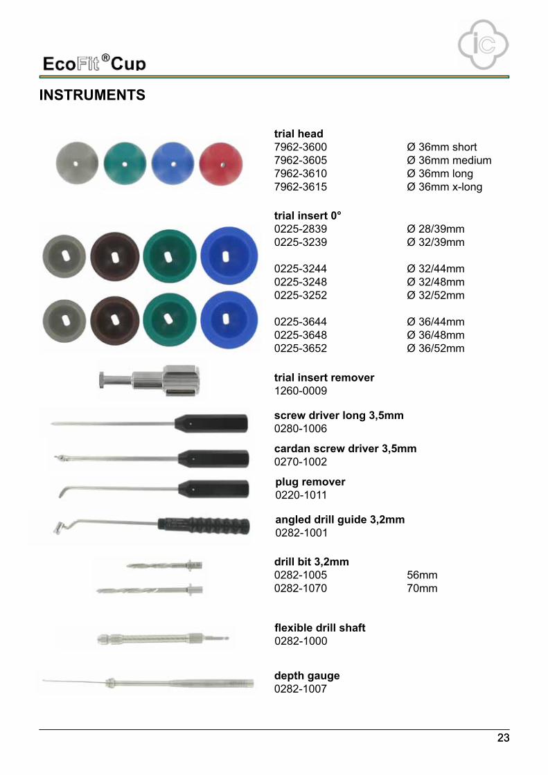
trial head7962-3600 Ø 36mm short7962-3605 Ø 36mm medium7962-3610 Ø 36mm long7962-3615 Ø 36mm x-long
insTrumenTs
trial insert 0°0225-2839 Ø 28/39mm0225-3239 Ø 32/39mm
0225-3244 Ø 32/44mm0225-3248 Ø 32/48mm0225-3252 Ø 32/52mm
0225-3644 Ø 36/44mm0225-3648 Ø 36/48mm0225-3652 Ø 36/52mm
trial insert remover1260-0009
screw driver long 3,5mm0280-1006
cardan screw driver 3,5mm0270-1002
plug remover0220-1011
angled drill guide 3,2mm0282-1001
drill bit 3,2mm0282-1005 56mm0282-1070 70mm
flexible drill shaft0282-1000
depth gauge0282-1007

0482
Your local distributor:
implantcast gmbhlüneburger schanze 26
21614 Buxtehude Germany
phone: +49 4161 744-0 fax: +49 4161 744-200
e-mail: [email protected] internet: www.implantcast.de E
CO
CU
OP
E-2
2041
2
*+E1
ICEC
OCUO
PE++
**+
$$E1
IC22
0412
++*