Embed Size (px)
Citation preview

Table of Contents
Subject Page
ME 9.2 . . . . . . . . . . . . . . . . . . . . . . . . . . . . . . . . . . . . . . . . . . . . . . . . . . . .2Objectives of the Module . . . . . . . . . . . . . . . . . . . . . . . . . . . . . . . . . . . . .2Purpose of the System . . . . . . . . . . . . . . . . . . . . . . . . . . . . . . . . . . . . . . .3System Components . . . . . . . . . . . . . . . . . . . . . . . . . . . . . . . . . . . . . . . .4
Power Supply . . . . . . . . . . . . . . . . . . . . . . . . . . . . . . . . . . . . . . . . . . . . . .8Principle of Operation . . . . . . . . . . . . . . . . . . . . . . . . . . . . . . . . . . . . . . . .9Integrated Voltage Supply Module . . . . . . . . . . . . . . . . . . . . . . . . . . . . . . 10Engine Wiring Harness . . . . . . . . . . . . . . . . . . . . . . . . . . . . . . . . . . . . . . 11
Air Management . . . . . . . . . . . . . . . . . . . . . . . . . . . . . . . . . . . . . . . . . . . .12Variable Intake Manifold . . . . . . . . . . . . . . . . . . . . . . . . . . . . . . . . . . . . . .14 Valvetronic . . . . . . . . . . . . . . . . . . . . . . . . . . . . . . . . . . . . . . . . . . . . . . . 15Principle of Operation . . . . . . . . . . . . . . . . . . . . . . . . . . . . . . . . . . . . . . . 19
Fuel Management . . . . . . . . . . . . . . . . . . . . . . . . . . . . . . . . . . . . . . . . . . 24Principle of Operation . . . . . . . . . . . . . . . . . . . . . . . . . . . . . . . . . . . . . . . 31
Ignition Management . . . . . . . . . . . . . . . . . . . . . . . . . . . . . . . . . . . . . . . .35Principle of Operation . . . . . . . . . . . . . . . . . . . . . . . . . . . . . . . . . . . . . . . 38
Emissions Management . . . . . . . . . . . . . . . . . . . . . . . . . . . . . . . . . . . . . 41Evaporative Emissions . . . . . . . . . . . . . . . . . . . . . . . . . . . . . . . . . . . . . . 41Exhaust Emissions . . . . . . . . . . . . . . . . . . . . . . . . . . . . . . . . . . . . . . . . .45Bosch LSU Oxygen Sensor . . . . . . . . . . . . . . . . . . . . . . . . . . . . . . . . . . 46Secondary Air Injection. . . . . . . . . . . . . . . . . . . . . . . . . . . . . . . . . . . . . . 50Principle of Operation . . . . . . . . . . . . . . . . . . . . . . . . . . . . . . . . . . . . . . 53
Performance Controls . . . . . . . . . . . . . . . . . . . . . . . . . . . . . . . . . . . . . . .62Bi-VANOS . . . . . . . . . . . . . . . . . . . . . . . . . . . . . . . . . . . . . . . . . . . . . . . 62Oil Condition . . . . . . . . . . . . . . . . . . . . . . . . . . . . . . . . . . . . . . . . . . . . . 66Electric Cooling Fan . . . . . . . . . . . . . . . . . . . . . . . . . . . . . . . . . . . . . . . . 67Alternator . . . . . . . . . . . . . . . . . . . . . . . . . . . . . . . . . . . . . . . . . . . . . . . 68Electronic Box Cooling Fan . . . . . . . . . . . . . . . . . . . . . . . . . . . . . . . . . . . 70Comfort Start . . . . . . . . . . . . . . . . . . . . . . . . . . . . . . . . . . . . . . . . . . . . .70Cruise Control . . . . . . . . . . . . . . . . . . . . . . . . . . . . . . . . . . . . . . . . . . . .73
Review Questions . . . . . . . . . . . . . . . . . . . . . . . . . . . . . . . . . . . . . . . . . . 76

35ME 9.2 Ignition Management
Ignition Management
Ignition Coils: The high voltage supply required to ignite the mixture in the combustionchambers is determined by the stored energy in the ignition coils. The stored energy con-tributes to the ignition duration, ignition current and rate of high voltage increase. The Coilcircuit including primary and secondary components consists of:
The Coil Assembly contains two copper windings insulated from each other. One windingis the primary winding, formed by a few turns of thick wire. The secondary winding isformed by a great many turns of thin wire.
The primary winding receives battery voltage from the Ignition Coil Relay (in the IVM) whichis activated by the CAS Module. The ECM provides a ground path for the primary coil (CoilTerminal 1) by activating a Final Stage transistor. The length of time that current flowsthrough the primary winding is the “dwell” which allows the coil to “saturate” or build up amagnetic field. After this storage process, the ECM will interrupt the primary circuit at thepoint of ignition by deactivating the Final Stage transistor. The magnetic field built up with-in the primary winding collapses and induces the ignition voltage in the secondary winding.
The high voltage generated in the secondarywinding is discharged through Coil Terminal 4to the spark plug (insulated by the boot con-nector).
The primary and secondary windings are un-coupled, therefore, the secondary windingrequires a ground supply (Coil Terminal 4a).
42-04-00
Insulator Boot
Secondary Winding
Ignition Coil
1. Coil Assembly2. Insulator Boot3. Spark Plug4. ECM Final Stage Transistor5. Secondary Coil Ground
42-04-01

36ME 9.2 Ignition Management
There is an individual ignition circuit and coil foreach cylinder on the ME 9.2 system. The ME9.2 uses “pencil type” ignition coils manufac-tured by Bremi. The eight individual ignition coilsare integrated with the insulated connector(boot).
The coils are removed by lifting the swivel latch connector retainer to release the wiring har-ness, apply a slight twist and lift the assembly upwards. The primary ignition cables arerouted on the top of the cylinder head covers.
Spark Plugs: The spark plugs introduce the ignition energyinto the combustion chamber. The high voltage “arcs” acrossthe air gap in the spark plug from the positive electrode to thenegative electrodes. This creates a spark which ignites thecombustible air/fuel mixture.
The spark plugs are located in the center of the combustionarea (on the top of the cylinder heads) which is the most suit-able point for igniting the compressed air/fuel mixture. Thecorrect spark plugs for the ME 9.2 are the NGK BKR6EQUPquad electrode (non-adjustable gap).
The Ignition System is monitored by the ECM via the Crankshaft Position/RPM Sensor. If aMisfire fault is present, the ECM will deactivate the corresponding fuel injector for that cylin-der. Engine operation will still be possible.
Knock Sensors: These are required to prevent detonation (pinging) from damaging theengine. The Knock Sensor is a piezoelectric sound conductor microphone. The ECM willretard the ignition timing (cylinder selective) based on the input of these sensors.
There are four Knock Sensors bolted to thecylinder heads between cylinders 1 & 2, 3 & 4,5 & 6 and 7 & 8. If the signal value exceeds thethreshold, the ECM identifies the “knock” andretards the ignition timing for that cylinder.
If a fault is detected with the sensor(s), the ECMdeactivates Knock Control the ignition timingwill be set to a conservative basic setting basedon intake air temperature and a fault will bestored.
42-04-02
42-04-03
42-04-04

37ME 9.2 Ignition Management
Camshaft Position Sensor (Cylinder Identification): The camshaft sensors (Hall type)inputs allows the ECM to determine camshaft positions in relation to crankshaft position. Itis used by the ECM to establish the “working cycle” of the engine for precise ignition tim-ing. For details about the sensor, refer to the Fuel Management section.
Accelerator Pedal Position (PWG): As the accelerator pedal is actuated, the ECM willadvance the ignition timing. The “full throttle” position indicates maximum acceleration tothe ECM, the ignition will be advanced for maximum torque. For details about the sensor,refer to the Air Management section.
Hot-Film Air Mass Meter (HFM): The air volume input signal is used by the ECM to deter-mine the amount of ignition timing advance. For details about the sensor, refer to the AirManagement section.
Air Temperature: This signal allows the ECM to make a calculation of air density. The sen-sor is located in the HFM. The ECM will adjust the ignition timing based on air temperature.If the intake air is hot the ECM retards the ignition timing to reduce the risk of detonation. Ifthe intake air is cooler, the ignition timing will be advanced. If this input is defective, a faultcode will be set and the ignition timing will be set to a conservative basic setting. For detailsabout the sensor, refer to the Air Management section.
Notes:

Principle of Operation
Ignition Management provides ignition to the combustion chambers with the required volt-age at the correct time. Based on the combination of inputs, the ECM calculates and con-trols the ignition timing and secondary output voltage by regulating the activation anddwell of the primary ignition circuit. The ECM controls and monitors the primary ignitioncircuit as well as the secondary ignition output (Misfire Detection).
The ECM has a very “broad” range of ignition timing. This is possible by using a DirectIgnition System, or sometimes referred to as “Static Ignition System”. Reliability is alsoincreased by having separate individual ignition circuits.
The Ignition Control is determined by the ECM (load dependent). The ECM will calculatethe engine “load” based on a combination of the following:
The dwell time will be regulated based on battery voltage. When cranking, the voltage islow and the ECM will increase the dwell to compensate for saturation “lag time”. When theengine is running and the battery voltage is higher, the ECM will decrease the dwell due toa faster saturation time.
The Crankshaft Position/RPM signals the ECM to start ignition in firing order (1-5-4-8-6-3-7-2) as well as providing information about the engine operation. This input is used in com-bination with other inputs to determine engine load which advances/retards the ignition tim-ing. Without this input, the ECM will not activate the ignition.
Cold start is determined by the ECM based on the engine coolant temperature and rpmduring start up. A cold engine will crank over slower than a warm engine, the ignition tim-ing will range between top dead center to slightly retarded providing optimum starting.
When starting a warm engine, the rpm is higher which results in slightly advanced timing.If the engine coolant and intake air temperature is hot, the ignition timing will not beadvanced reducing starter motor “load”.
During cranking, the ECM recognizes the CamshaftPosition (compression stroke) and activates the igni-tion per cylinder (firing order).
Multiple Ignition Pulses ensure good spark quality dur-ing engine start up. The ECM will activate the ignitioncoils multiple times (1) per 720º of crankshaft revolu-tion.
38ME 9.2 Ignition Management

The ignition timing will be progressively advanced assisting the engine in coming up tospeed. As the engine speed approaches idle rpm, the timing remains slightly advanced toboost torque. When the engine is at idle speed, minimum timing advance is required. Thiswill allow faster engine and catalyst warm up. The multiple pulsing switches to single pulsewhen engine speed >1350 RPM (varied with engine temperature).
The timing will be advanced when the ECM observes low engine rpm and increasing accel-erator/air volume inputs (acceleration torque). As the Valvetronic valve lift is increased, theECM advances the timing based on the engine acceleration request (and at what rate). TheECM will fully advance timing for the “full throttle” position indicating maximum acceleration(torque).
The Air Flow Volume signal provides the measured amount of intake air volume. This inputis used by the ECM to determine the amount of timing advance to properly combust theair/fuel mixture.
The Air Temperature Signal assists the ECM in reducing the risk of detonation (ping). If theintake air is hot the ECM retards the ignition timing. If the intake air is cooler, the ignitiontiming will be advanced.
As the Valvetronic valve lift is decreased, the ECM decreases the ignition timing if the rpmis above idle speed (coasting). This feature lowers the engine torque for deceleration. Whenthe engine rpm approaches idle speed, the timing is slightly advanced to prevent the enginefrom stalling. The amount of advance is dependent upon the engine temperature and therate of deceleration.
Emission Optimized - IGNITION KEY OFF
“Emission Optimized Ignition Key Off” is a programmed feature of the CAS Module. Afterthe CAS Module detects KL 15 is switched “off”, the ignition coil relay (in the IVM) staysactive (CAS voltage supply) for two more individual coil firings. This means that just twocylinders are fired - not two revolutions.
This feature allows residual fuel injected into the cylinders, as the ignition key is switchedoff, to be combusted as the engine runs down.
When KL15 is switched “off” the ECM removes the operating voltage from the fuel injec-tion relay (in the IVM). The CAS Module will maintain power to the ignition coil relay for afew seconds to maintain ignition coil activation (by the ECM).
39ME 9.2 Ignition Management

Knock Control
The use of Knock Control allows the ECM to further advance the ignition timing under loadfor increased torque. This system uses four Knock Sensors located between cylinders 1 &2, cylinders 3 & 4, cylinders 5 & 6 and cylinders 7 & 8. Knock Control is only in affect whenthe engine temperature is greater than 35 ºC and there is a load on the engine. This will dis-regard false signals while idling or from a cold engine.
Based on the firing order, the ECM monitors the Knock Sensors after each ignition for anormal (low) signal. If the signal value exceeds the threshold, the ECM identifies the “knock”and retards the ignition timing (3º) for that cylinder the next time it is fired.
This process is repeated in 3º increments until the knock ceases. The ignition timing will beadvanced again in increments right up to the knock limit and maintain the timing at thatpoint.
If a fault is detected with the Knock Sensor(s) or circuits, the ECM deactivates KnockControl. The ignition timing will be set to a conservative basic setting (to reduce the risk ofdetonation) and a fault will be stored.
40ME 9.2 Ignition Management
42-04-05

41ME 9.2 Emissions Management
Emissions Management
Evaporative Emissions: The control of the evaporative fuel vapors (Hydrocarbons) fromthe fuel tank is important for the overall reduction in vehicle emissions.
The evaporative system has been combined with the ventilation of the fuel tank, whichallows the tank to breath (equalization). The overall operation provides:
• An inlet vent, to an otherwise "sealed" fuel tank, for the entry of air to replace the fuelconsumed during engine operation.
• An outlet vent with a storage canister to "trap and hold" fuel vapors that are producedby the expansion/evaporation of fuel in the tank, when the vehicle is stationary.
The canister is then "purged" using the engine vacuum to draw the fuel vapors into thecombustion chamber. This "cleans" the canister allowing for additional storage. Like anyother form of combustible fuel, the introduction of these vapors on a running engine mustbe controlled. The ECM controls the Evaporative Emission Valve which regulates purging ofevaporative vapors.
On-Board Refueling Vapor Recovery (ORVR): The ORVR system recovers and storeshydrocarbon fuel vapor during refueling. Non ORVR vehicles vent fuel vapors from the tankventing line back to the filler neck and in many states reclaimed by a vacuum receiver onthe filling station’s fuel pump nozzle.
When refueling, the pressure of the fuel entering the tank forces the hydrocarbon vaporsthrough the tank refuelling breather hose (24 on the following page) to the liquid/vaporexpansion tank and into the active charcoal canister.
The HC vapors are stored in the active charcoal canister and the system can then “breath”through the DM TL and the air filter.

42ME 9.2 Emissions Management
42-04-00
Fuel System
1. Air Cleaner 16. Service vent valve (float valve)2. Intake manifold 17. Anti-spitback flap3. Engine 18. Surge chamber (fuel pump baffling)4. Exhaust system 19. Electric fuel pump (EKP)5. Oxygen Sensor 20. Pressure relief valve6. Evaporative emission valve (TEV) 21. Suction jet pump7. ECM 22. Fuel tank8. Purge vapors 23. Outlet protection valve9. Carbon canister 24. Refueling breather
10. Fuel tank leak diagnostic module (DM-TL) 25. Fuel Filter11. Roll-over valve 26. Fuel pressure regulator (3.5 bar)12. Dust filter 27. Injection rail13. Service ventilation 28. Float valve14. Pressure test lead 29. Liquid/vapor expansion tank15. Fuel tank cap 30. Filler vent valve

43ME 9.2 Emissions Management
Liquid/Vapor Expansion Tank: Fuel vapors are rout-ed from the refuelling breather hose and the ServiceVentilation hose to the Liquid/Vapor Expansion Tank (1)located in the right rear fender well.
The vapors cool when exiting the fuel tank, condenseand drain back to the fuel tank. The remaining vaporsexit the Liquid/Vapor Expansion Tank to the ActiveCarbon Canister.
Active Carbon Canister: As the fuel vapors enter thecanister, they will be absorbed by the active carbon.The remaining air will be vented to the atmospherethrough the end of the canister (passing through theDM TL and filter) allowing the fuel tank to “breath”.
When the engine is running, the canister is then "purged" using intake manifold vacuum todraw fresh air through the canister which extracts the hydrocarbon vapors into the com-bustion chamber. This cleans the canister for additional storage. The Active CarbonCanister (2) is combined with the DM TL Pump and is located in the right rear fender well.
Evaporative Emission Valve: This ECM controlled solenoid valve (located on the front ofthe engine) regulates the purge flow from the Active Carbon Canister through the air inletpipe into the intake manifold.
The ECM Relay (in the IVM) provides operatingvoltage, and the ECM controls the valve by reg-ulating the ground circuit. The valve is poweredopen and closed by an internal spring.
If the Evaporative Emission Valve circuit isdefective, a fault code will be set. If the valve is“mechanically” defective, a driveability com-plaint could be encountered and a mixture relat-ed fault code will be set.
1
2
42-04-01
42-04-02

44ME 9.2 Emissions Management
DMTL (Diagnosis Module - Evaporative LeakageDetection): This component ensures accurate fuelsystem leak detection for leaks as small as 0.5 mm(.020”) by slightly pressurizing the fuel tank and evapo-rative components. The DM TL pump contains an inte-gral DC motor which is activated directly by the ECM.The ECM monitors the pump motor operating currentas the measurement for detecting leaks.
The pump also contains an ECM controlled changeover valve that is energized closed during a LeakDiagnosis test. The change over valve is open during allother periods of operation allowing the fuel system to“breath” through the inlet filter. The DM TL is locatedwith the Active Carbon Canister.
1. In its inactive state, filtered fresh air enters the evap-orative system through the sprung open valve of theDM TL.
2. When the ECM activates the DM TL for leak testing,it first activates only the pump motor. This pumps airthrough a restricted orifice (0.5 mm) which causesthe electric motor to draw a specific amperage value(20-30 mA). This value is equivalent to the size of therestriction.
3. The solenoid valve is then energized which seals theevaporative system and directs the pump output topressurize the evaporative system.
• A large leak is detected in the evaporative system if the amperage value is not achieved.
• A small leak is detected if the same reference amperage is achieved.
• The system is sealed if the amperage value is high-er than the reference amperage.
�
2
3
42-04-04
42-04-05
42-04-03

45ME 9.2 Emissions Management
Exhaust Emissions: The combustion process of a gasoline powered engine producesCarbon Monoxide (CO), Hydrocarbons (HC) and Oxides of Nitrogen (NOx).
• Carbon Monoxide is a product of incomplete combustion under conditions of air defi- ciency. CO emissions are strongly dependent on the air/fuel ratio.
• Hydrocarbons are also a product of incomplete combustion which results in unburned fuel. HC emissions are dependent on air/fuel ratio and the ignition of the mixture.
• Oxides of Nitrogen are a product of peak combustion temperature (and temperature duration). NOx emissions are dependent on internal cylinder temperatures affected by the air/fuel ratio and ignition of the mixture.
Control of exhaust emissions is accomplished by the engine and engine managementdesign as well as after-treatment.
• The ECM manages exhaust emissions by controlling the air/fuel ratio and ignition.
• The ECM controlled Secondary Air Injection further dilutes exhaust emissions leaving the engine and reduces the catalysts warm up time.
• The Catalytic Converter further reduces exhaust emissions leaving the engine.
Oxygen Sensors: The N62 engine is fitted with a total of four oxygen sensors. One planarbroadband oxygen sensor (constant characteristic curve), which regulates the fuel-air mix-ture, is located upstream (2) of each of the two catalytic converters. The catalytic convert-er assemblies are integral with the exhaust manifolds (1).
There is a post catalytic converter sensor (Bosch LSH25) foreach cylinder bank positioned downstream of the catalyticconverter (3) which monitors the catalyst efficiency.
This monitoring means that if the exhaust gas concentration istoo high, a fault code is stored. The post catalyst sensors canalso detect an emission relevant fault in a pre-catalyst oxygensensor. 43-02-06

46ME 9.2 Emissions Management
Bosch LSU Planar Wideband Oxygen Sensor: The N62 engine is equipped with newplanar wideband oxygen sensors (pre-catalyst). The sensor is planar shaped (type of con-struction) which is more compact and is made up of thin layers of zirconium dioxide (ZrO2)ceramic films. This modular lamination structure enables the integration of several functionsincluding the heating element which ensures the minimum operating temperature (750 ºC)is reached rapidly.
In contrast to conventional oxygen sensors, the wideband features can measure not onlyat Lambda=1, but also in the rich and extremely lean range (Lambda=0.7 to completeatmospheric oxygen) very rapidly.
To operate effectively, the oxygen sensor requires ambient air as the “reference gas” insidethe sensor. The ambient air reaches the inside of the sensor through the plug connectionand through the harness. The plug connection socket must therefore be protected fromcontamination (wax, preservatives, engine degreasers, engine washing, etc.). In the eventof the oxygen sensor malfunctioning, the connector should always be checked first withregard to contamination and cleaned if necessary. The plug connection must be discon-nected and then reconnected to remove any oxidation from the connector pins.
The pump cell (2) and reference cell (9) are made of zirconium dioxide and each coated withtwo porous platinum electrodes. They are arranged so that there is a measuring gap (8) ofapprox. 10 to 50 microns between them. This measuring gap is connected by an inletopening to the exhaust gas (1). The pump cell is controlled by the ECM applying voltage tothe electrodes to initiate oxygen ion pumping across the porous membrane of the referencecell, providing a quicker response time.
42-04-07
Sensor Element Design
1. Exhaust gas2. Pump cell3. Platinum electrode, reference cell4. Heating element5. Heating element6. Reference air gap7. Zirconium ceramic layer8. Measuring gap9. Reference Cell
10. Platinum electrode, reference cell11. Platinum electrode, pump cell12. Platinum electrode, pump cell

47ME 9.2 Emissions Management
If the exhaust gas content is lean, the pump cell pumps oxygen away from the measuringgap to the outside. The direction of flow is reversed for rich exhaust gas content, then oxy-gen is pumped from the exhaust gas into the measuring gap. The pump current flow is pro-portional to the oxygen concentration (lean) or the oxygen requirement (rich). The pump isconstantly working to maintain that the gas composition in the measuring gap is constant-ly at Lambda=1. The required current of the pump cell is evaluated by the ECM as a sig-nal that represents oxygen content in the exhaust gas.
Oxygen Sensor Signals
The sensor conductivity is efficient when the oxygen sensor is hot (750º C). For this reason,the sensor contains a heating element. This reduces warm up time, and retains the heatduring low engine speed when the exhaust temperature is cooler. The oxygen sensor heat-ing elements receive power from the IVM (12 V) and the ground sypply is pulse width mod-ulated by the ECM.
The monitored voltage signal is constantly changing due to combustion variations and nor-mal exhaust pulsations.
• At a value of Lambda =1, the pump cell requires approx. 3 mA.The oxygen sensor signal voltage is approx. 1.5VThe reference cell voltage is approx. 450mV
• At a Lambda value <1 (rich), the oxygen sensor signal voltage is approx. 0.3V
• At a Lambda value >1 (lean), the oxygen sensor signal voltage is approx. 4.3V
If necessary, the ECM will “correct” the air/fuel ratio by regulating the ms injection time. TheECM monitors the length of time the sensors are operating in the lean, rich and rest condi-tions. The evaluation period of the sensors is over a predefined number of oscillation cyclesand pump cell amperage.
Catalytic Converter Monitoring: The efficiency of catalyst operation is determined byevaluating the oxygen storage capability of the ceramic monolyth catalytic converters usingthe pre and post oxygen sensor signals.
A properly operating catalyst consumes or stores most of the O2 (oxygen) that is presentin the exhaust gas (input to catalyst). The gases that flow into the catalyst are convertedfrom CO, HC and NOx to CO2, H2O and N2 respectively.

48ME 9.2 Emissions Management
In order to determine if the catalysts are working correctly, post catalyst oxygen sensors areinstalled to monitor exhaust gas content exiting the catalysts. The signal of the post cat. O2
sensor is evaluated over the course of several pre cat. O2 sensor oscillations.
During the evaluation period, the signal of thepost cat. sensor must remain within a relativelyconstant voltage range (700 - 800 mV).
The post cat. O2 voltage remains high with avery slight fluctuation. This indicates a furtherlack of oxygen when compared to the pre cat.sensor. If this signal decreased in voltage and/orincreased in fluctuation, a fault code will be setfor Catalyst Efficiency.
Bosch LSH 25 Oxygen Sensors: The post catalyst oxygen sensors produces a low volt-age (0-1000 mV) proportional to the oxygen content exiting the catalytic converters.
1 2 3 4 5 6 7 8 9 10
12 (
(
)
)
11
+
ExhaustStream
Ambient Air
42-04-09ExhaustStream
Ambient Air
Oxygen Sensors
42-04-08
1. Electrode (+) 7. External Body (Ventilated)2. Electrode (-) 8. Contact Spring3. Porous Ceramic Coating (encasing electrolyte) 9. Vent Opening4. Protective Metal Cage (Ventilated) 10. Ouput Lead5. Casing 11. Insulator6. Contact Sleeve 12. Exhaust Pipe Wall

49ME 9.2 Emissions Management
The “tip” of the sensor contains a microporous platinum coating (electrodes) which conductcurrent. The platinum electrodes are separated by solid electrolyte which conducts oxygenions. The platinum conductors are covered with a highly porous ceramic coating and theentire tip is encased in a ventilated metal “cage”.
This assembly is submersed in the exhaust stream. The sensor body (external) has a smallvent opening in the housing that allows ambient air to enter the inside of the tip.
The ambient air contains a constant level of oxygen content (21%) and the exhaust streamhas a much lower oxygen content. The oxygen ions (which contain small electrical charges)are “purged” through the solid electrolyte by the hot exhaust gas flow. The electricalcharges (low voltage) are conducted by the platinum electrodes to the sensor signal wirethat is monitored by the ECM.
If the exhaust has a lower oxygen content (rich mixture), there will be a large ion “migration”through the sensor generating a higher voltage (950 mV).
If the exhaust has a higher oxygen content (lean mixture), there will be a small ion “migra-tion” through the sensor generating a lower voltage (080 mV).
This conductivity is efficient when the oxygen sensor is hot (250º - 300º C). For this reason,the sensor contains a heating element. This “heated” sensor reduces warm up time, andretains the heat during low engine speed when the exhaust temperature is cooler.
42-04-10

50ME 9.2 Emissions Management
Secondary Air Injection: Injecting ambient air into the exhaust stream after a cold enginestart reduces the warm up time of the catalysts and reduces HC and CO emissions. TheECM controls and monitors the Secondary Air Injection.
An Electric Air Pump and Air Injection Valves direct fresh air through internal channels in thecylinder heads into the exhaust ports.
Secondary Air Pump (SLP): The electrically-operated secondary air pump is mounted tothe vehicle body. The pump draws out filtered fresh air from the air cleaner housing duringthe warm-up phase and supplies it to the two secondary air injection valves.
Once the engine has been started, the secondary air pump is supplied with voltage by theSecondary Air Pump Relay (located in front of the glovebox) which is activated by the ECM.It remains switched on until the engine has taken in a certain amount of air. The ON periodmay be a maximum of 90 seconds and it depends on the following engine operating con-ditions:
• Coolant temperature (from -10 ºC to approximately 60 ºC)
• Ambient air temperature (from the HFM)
• Engine speed
The power is supplied from the fuse junction(#102 - 50 Amp) located on the right inner fend-er of the engine compartment (under theremote charging post) for the relay to energizethe SLP.
43-04-05
1. Air Intake Duct2. Air Cleaner housing with Intake Air Silencer3. Intake Pipe with HFM
(Hot-Film Air Mass Flow Sensor)4. Secondary Air Valves5. Secondary Air Pump
Secondary Air System
51ME 9.2 Emissions Management
Non-return Valves (SLV): One non-returnvalve is mounted on each cylinder head.
The Non-return valves are opened by the air pressure generated from the secondary airpump. The secondary air is led through a pipe to the secondary air ducts (integral in thecylinder heads) for distribution into the exhaust ports. There are two outlets in each exhaustport next to the exhaust valve guides.
The Non-return valves are sprung closed as soon as the secondary air pump is switchedoff. This prevents exhaust vapors, pressure and condensation from flowing back to the sec-ondary air pump.
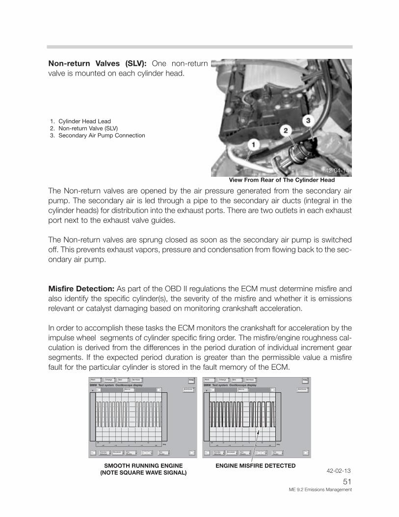
Misfire Detection: As part of the OBD II regulations the ECM must determine misfire andalso identify the specific cylinder(s), the severity of the misfire and whether it is emissionsrelevant or catalyst damaging based on monitoring crankshaft acceleration.
In order to accomplish these tasks the ECM monitors the crankshaft for acceleration by theimpulse wheel segments of cylinder specific firing order. The misfire/engine roughness cal-culation is derived from the differences in the period duration of individual increment gearsegments. If the expected period duration is greater than the permissible value a misfirefault for the particular cylinder is stored in the fault memory of the ECM.
42-04-14
1. Cylinder Head Lead2. Non-return Valve (SLV)3. Secondary Air Pump Connection
View From Rear of The Cylinder Head
42-02-13

52ME 9.2 Emissions Management
Depending on the level of misfire rate measured the ECM will illuminate the "MalfunctionIndicator Light”, deactivate the specific fuel injector to the particular cylinder and switchlambda operation to open-loop.
In order to eliminate misfire faults that can occur as a result of varying flywheel tolerances(manufacturing process) an internal adaptation of the flywheel is made. The adaptation ismade during periods of decel fuel cut-off in order to avoid any rotational irregularities whichthe engine can cause during combustion. This adaptation is used to correct segment dura-tion periods prior to evaluation for a misfire event.
If the sensor wheel adaptation has not been completed the misfire thresholds are limited toengine speed dependent values only and misfire detection is less sensitive. The crankshaftsensor adaptation is stored internally and if the limit is exceeded a fault will be set.
Notes:
53ME 9.2 Emissions Management
Principle of Operation
Emissions Management controls evaporative and exhaust emissions. The ECM monitorsthe fuel storage system for evaporative leakage and controls the purging of evaporativefuel. The ECM monitors and controls the exhaust emissions by regulating the combustiblemixture and after treating by injecting fresh air into the exhaust system. The catalytic con-verters further break down remaining combustible exhaust gases and is monitored by theECM for catalyst efficiency.
The Evaporative Leakage Detection is performed on the fuel storage system by theDM TL pump which contains an integral DC motor that is activated by the ECM. The ECMmonitors the pump motor operating current as the measurement for detecting leaks.
The DM TL generates a pressure of 20-30 mbar in the fuel tank and evaporative system.The electrical current required for this is calculated by the ECM serves as the indirect valuefor the tank pressure.
The DM TL carries out a reference measurement before each measurement. This is per-formed by building up a pressure for 10-15 seconds using an internal orifice of 0.5 mm asa reference and the ECM monitors the current required by the pump motor (20-30 mA).
If a lower pressure is detected in the pressure build-up (low current draw) as compared tothe reference measurement, this indicates a leak in the fuel tank/evaporative system. If ahigher pressure is detected (higher current draw), the system does not have a leak.
The pump also contains an ECM controlled change over valve that is energized closed dur-ing a Leak Diagnosis test. The ECM only initiates a leak diagnosis test every second timethe criteria is met. The criteria is as follows:
• Engine OFF with ignition switched OFF.
• ECM still in active state or what is known as “follow up mode” (ECM Relay energized,ECM and components online for extended period after key off).
• Prior to Engine/Ignition switch OFF condition, vehicle must have been driven for a min-imum of 20 minutes.
• Prior to minimum 20 minute drive, the vehicle must have been OFF for a minimum of 5hours.
• No faults in the ECM for DM TL / tank venting system.

54ME 9.2 Emissions Management
• Fuel Tank Capacity must be between 10 and 90% (safe approximation between 1/4 -3/4 of a tank).
• Ambient Air Temperature between -7OC & 35OC
• Altitude < 2500m (8,202 feet).
• Battery Voltage between 11.5 and 14.5 Volts
When these criteria are satisfied every second time, the ECM will start the Fuel SystemLeak Diagnosis Test. The test will typically be carried out once a day ie:, once after drivingto work in the morning, when driving home in the evening, the criteria are once again metbut the test is not initiated. The following morning, the test will run again.
PHASE 1 - REFERENCE MEASUREMENT
The ECM activates the pump motor. The pump pulls air from the filtered air inlet and pass-es it through a precise 0.5 mm reference orifice in the pump assembly.
The ECM simultaneously monitors the pump motor current flow. The motor current raisesquickly and levels off (stabilizes) due to the orifice restriction. The ECM stores the stabilizedamperage value in memory. The stored amperage value is the electrical equivalent of a 0.5mm (0.020”) leak.
PHASE 2 - LEAK DETECTION
The ECM energizes the Change Over Valve allowing the pressurized air to enter the fuelsystem through the Charcoal Canister. The ECM monitors the current flow and comparesit with the stored reference measurement over a duration of time.
The time taken for the measurement is:• 60-220 seconds if there are no leaks• 200-360 seconds if there is a leak measuring 0.5 mm (small leak)• 30-80 seconds if there is a leak measuring over 1 mm (large leak)
The evaporative emission valve is closed during the measurement. The time taken for themeasurement is dependant on how much fuel there is in the tank.
Once the test is concluded, the ECM stops the pump motor and immediately de-energizesthe change over valve. This allows the stored pressure to vent thorough the charcoal can-ister trapping hydrocarbon vapor and venting air to atmosphere through the filter.

55ME 9.2 Emissions Management
Test Results
The time duration varies between30 & 360 seconds depending onthe resulting leak diagnosis testresults (developed tank pressure“amperage” within a specific timeperiod).
When the ECM detects a leak, afault will be stored and the“Malfunction Indicator Light” willbe illuminated. Depending on theamperage measurement detect-ed by the ECM, the fault codedisplayed will be “small leak” or“large leak”.
Refuelling While a Leak Diagnosis is Taking Place: The ECM detects refuelling duringa leak diagnosis as a result of the pressure drop when the fuel filler cap is opened and theincrease pressure while filling the tank is being filled.
In this case, the leakage diagnosis is interrupted. The solenoid valve in the DM TL is swi-tched off and the tank pressure escapes through the activated carbon canister.
If refuelling does not take place immediately after the fuel filler cap has been opened, thesystem will detect a large leak and the a fault will be stored in the ECM. If refuelling isdetected in the next driving cycle (increase in fuel level), the fault is cleared.
The ECM detects refueling from a change in the fuel tanksending unit level. If the filler cap was not properly installed,when the leakage test is performed and leakage is detected;the variable indicator lamp (shown to the right) and the“Please Close Filler Cap” Check Control message will bedisplayed.
If the filler cap is correctly installed and leakage is not presentthe next time the test is performed, the “Malfunction IndicatorLight” will not be illuminated.
42-02-14
42-02-15

56ME 9.2 Emissions Management
Starting with 2002 MY, a heating element wasadded to the DM TL pump to eliminate con-densation.
The heater is provided battery voltage whenKL15 is switched “on” and the ECM providesthe ground path.
Catalyst Monitoring is performed by the ECM under oxygen sensor closed loop opera-tion. The changing air/fuel ratio in the exhaust gas results in lambda oscillations at the pre-catalyst sensors. These oscillations are dampened by the oxygen storage activity of thecatalysts and are reflected at the post catalyst sensors as a fairly stable signal (indicatingoxygen has been consumed). Conditions for Catalyst Monitoring:
Requirements Status/Condition
• Closed loop operation YES• Engine coolant temperature Operating Temp.• Vehicle road speed 3 - 50 MPH (5 to 80 km/h)• Catalyst temperature (calculated)* 350°C to 650°C• Valvetronic position deviation Steady • Engine speed deviation Steady/stable engine speed• Average lambda value deviation Steady/stable load
* Catalyst temperature is an ECM calculated value based on load/air mass and time.
Note: The catalyst efficiency is monitored once per trip while the vehicle is in closed loopoperation.

57ME 9.2 Emissions Management
As part of the monitoring process, the pre and post O2 sensor signals are evaluated by theECM to determine the length of time each sensor is operating in the rich and lean range.
If the catalyst is defective the post O2 sensor signal will reflect the pre O2 sensor signal(minus a phase shift/time delay), since the catalyst is no longer able to store/comsume oxy-gen. The catalyst monitoring process is stopped once the predetermined number of cyclesare completed, until the engine is shut-off and started again. After completing the next"customer driving cycle" whereby the specific conditions are met and a fault is again set,the "Malfunction Indicator Light” will be illuminated.
Secondary Air Injection Monitoring is performed by the ECM via the use of the pre-cat-alyst oxygen sensors. Once the air pump is active and is air injected into the exhaust sys-tem the oxygen sensor signals will indicate a lean condition. If the oxygen sensor signalsdo not change within a predefined time a fault will be set and identify the faulty bank(s).When diagnosing a Secondary Air Injection fault, in addition to the electric air pump andnon-return valves always consider the following:
• Restricted air inlet to the pump.• Restricted supply hoses to the non-return valves.• Internal restrictions in the cylinder head passages into the exhaust ports.
Misfire Detection is part of the OBD II regulations the ECM must determine misfire andalso identify the specific cylinder(s), the severity of the misfire and whether it is emissionsrelevant or catalyst damaging based on monitoring crankshaft acceleration.
Emission Increase:
• Within an interval of 1000 crankshaft revolutions, the ECM adds the detected misfire events for each cylinder. If the sum of all cylinder misfire incidents exceeds the pre-determined value, a fault code will be stored.
• If more than one cylinder is misfiring, all misfiring cylinders will be specified and the individual fault codes for all misfiring cylinders and for multiple cylinder will be stored.
Catalyst Damage:
• Within an interval of 200 crankshaft revolutions the detected number of misfiring events is calculated for each cylinder. The ECM monitors this based on load/rpm. If the sum of cylinder misfire incidents exceeds a predetermined value, a fault code is stored and the “Malfunction Indicator Light” will be illuminated.

58ME 9.2 Emissions Management
If the cylinder misfire count exceeds the predetermined threshold the ECM will take the fol-lowing measures:
• The oxygen sensor control will be switched to open loop.• The cylinder selective fault code is stored.• If more than one cylinder is misfiring the fault code for all individual cylinders and for
multiple cylinders will be stored.• The fuel injector to the respective cylinder(s) is deactivated.
The Integrated Ambient Barometric Pressure Sensor of the ME 9.2 is part of the ECMand is not serviceable. The internal sensor is supplied with 5 volts. In return it provides alinear voltage of approx. 2.4 to 4.5 volts representative of barometric pressure (altitude).
The ME 9.2 monitors barometric pressure for the following reasons:
• The barometric pressure signal along with calculated air mass provides an additional cor-rection factor to further refine injection “on” time.
• Provides a base value to calculate the air mass being injected into the exhaust systemby the Secondary Air Injection System. This correction factor alters the secondary airinjection “on” time, optimizing the necessary air flow into the exhaust system.
42-04-16

59ME 9.2 Emissions Management
The Malfunction Indicator Light is illuminated when the OBD system (integral in theECM) determines that a problem exists and a corresponding “Diagnostic Trouble Code” isstored in the ECM’s memory. The Malfunction Indicator appears both in the instrument clus-ter upper center section (fixed) and in the Check Control Display (variable indicator). Thislight informs the driver of the need for service with a Check Control message displayed.
After fixing the problem the fault code is deleted to turn off the light. If the conditions thatcaused a problem are no longer present, the OBD system can turn off the light automati-cally. If the OBD system evaluates the component or system three consecutive times andno longer detects the initial problem, the dashboard light will turn off automatically.
The Malfunction Indicator Light will illuminate for the following reasons:
• Pre-drive check when the ignition is switched on (in the fixed location)
• Increased emissions (both fixed and variable indicator locations with message dis-played)
• Engine fault - drive with moderation (variable indicator location with message dis-played)
Fixed Location
Variable Indicator Location42-04-18
60ME 9.2 Emissions Management
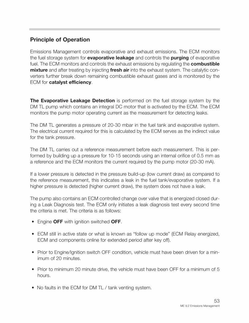
The Malfunction Indicator Light will illuminate with a “halfshading” in the variable indicator location for the following rea-sons:
• Engine fault - with reduced power (with message dis-played)
• Engine damage possible! (with message displayed)
Emissions Diagnosis
The "BMW Fast" (BMW fast access for service and testing) diagnosis concept is used inthe E65 for ME 9.2 ECM. This concept is based on the "Keyword Protocol 2000" (KWP2000) diagnosis protocol defined as part of the ISO 14230 standard. Diagnosis communi-cation takes place entirely on the basis of a transport protocol on the CAN bus. TheDiagnosis bus is connected to the Central Gateway Module (ZGM).
Vehicle Diagnosis Access Point
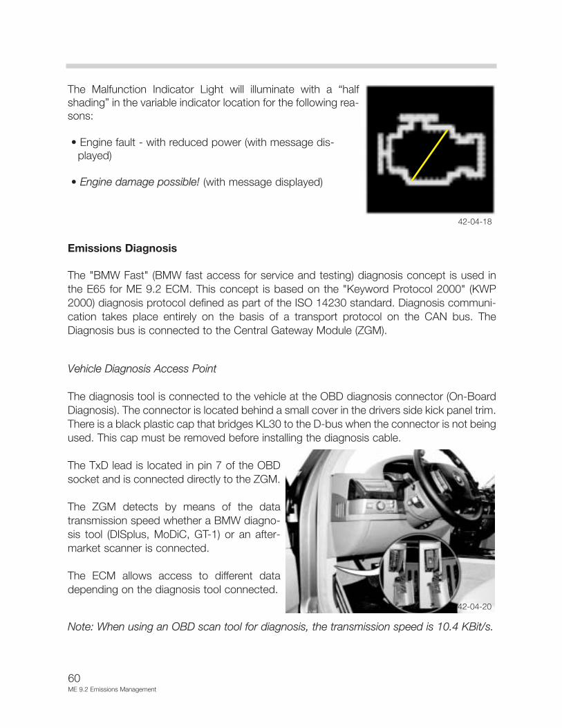
The diagnosis tool is connected to the vehicle at the OBD diagnosis connector (On-BoardDiagnosis). The connector is located behind a small cover in the drivers side kick panel trim.There is a black plastic cap that bridges KL30 to the D-bus when the connector is not beingused. This cap must be removed before installing the diagnosis cable.
The TxD lead is located in pin 7 of the OBDsocket and is connected directly to the ZGM.
The ZGM detects by means of the datatransmission speed whether a BMW diagno-sis tool (DISplus, MoDiC, GT-1) or an after-market scanner is connected.
The ECM allows access to different datadepending on the diagnosis tool connected.
Note: When using an OBD scan tool for diagnosis, the transmission speed is 10.4 KBit/s.
42-04-20
42-04-18

61ME 9.2 Emissions Management
Diagnosis Bus
The aim of diagnosis is to enable a Technician to reliably identify a defective component. Bythe use of appropriate hardware and monitoring software, the microprocessor of the diag-nosis tool is able to detect faults in the ECM and its peripherals.
Faults identified are stored in the fault memory and can be read out using the DiagnosisProgram. Data transfer between the vehicle and the diagnosis tool takes place via theDiagnosis bus (D bus).
The new features of the diagnosis bus are:
• Faster data transmission speed of 115 kBd.• Central diagnosis access point (OBD connector).• Single diagnostic cable (TxD II) for the entire vehicle.• Omission of the TxD1 cable.• Access to diagnosis functions requires “Authorization”.• Diagnosis protocol "KWP 2000" (Keyword Protocol 2000).• Standardized diagnosis structure for all control units.
The ECM is not directly connected to the OBD diagnostic connector. The OBD diagnosticconnector is connected to the ZGM. The ECM is connected to the ZGM (central gatewaymodule) by the PT CAN bus. The ECM is also connected to the Valvetronic control moduleby the Lo CAN (local) bus. Valvetronic faults are stored in the ECM.
42-04-21

62ME 9.2 Performance Controls
Performance Controls
Bi-VANOS Control (Variable Camshaft Adjustment)
Performance, torque, idle characteristics and exhaust emissions reduction are improved byVariable Camshaft Timing (Bi-VANOS). The VANOS units are mounted directly on the frontof the camshafts and adjusts the timing of the Intake and Exhaust camshafts from retard-ed to advanced. The ECM controls the operation of the Bi-VANOS solenoids which regu-lates the oil pressure required to move the VANOS units. Engine RPM, load and tempera-ture are used to determine Bi-VANOS activation.
The Bi-VANOS mechanical operation is dependent on engine oil pressure applied to posi-tion the VANOS units. When oil pressure is applied to the units (via ports in the camshaftsregulated by the solenoids), the camshaft hubs are rotated in the drive sprockets changingthe position which advances/retards the intake/exhaust camshafts timing. The Bi-VANOSsystem is “fully variable”. When the ECM detects that the camshafts are in the optimumpositions, the solenoids maintain oil pressure on the units to hold the camshaft timing.
The operation of the VANOS solenoids are monitored in accordance with the OBD IIrequirements for emission control. The ECM monitors the final stage output control and thesignals from the Camshaft Position Sensors for Bi-VANOS operation.
42-04-00

63ME 9.2 Performance Controls
Solenoid Valves: The Bi-VANOS solenoid valves are mount-ed through the upper timing case front cover. There are twosolenoids per cylinder head to control the oil flow to thecamshaft ports for the intake and exhaust VANOS units.
The 4/3 way proportional solenoid valve is activated by theECM to direct oil flow. The solenoid valve is sealed to the frontcover by a radial seal and secured by a retaining plate.
Hydraulic Actuation
When oil pressure is applied to chamber A, the blades are forced away from the VANOShousing (counterclockwise). The blades are keyed into the hub which results in the hubposition being rotated in relation to the housing (with sprocket). The hub is secured to thecamshaft which changes the camshaft to sprocket relationship (timing). The example belowshows the adjustment procedure together with the pressure progression based on theVANOS unit for the exhaust camshaft.
During this adjustment chamber B is open (through the solenoid) to allow the oil to drainback through the cylinder head (internal reservoir).
42-02-41
42-04-02
VANOS
1. Front View of VANOSUnit
2. Side View of VANOSUnit
3. Camshaft Oil Port(Chamber B)
4. Solenoid Valve
5. Engine Oil Pump
6. Supplied Oil (Switched Through Solenoid)
7. Supplied Oil Pressure (From Engine Oil Pump)

64ME 9.2 Performance Controls
When the solenoid valve switches over, oil pressure is applied to chamber B. This forcesthe blades (and hub) in a clockwise direction back to the initial position, again changing thecamshaft timing.
The example below shows the reset procedure together with the pressure progressionbased on the VANOS unit for the exhaust camshafts.
During this adjustment chamber A is open (through the solenoid) to allow the oil to drainback through the cylinder head (internal reservoir).
Camshaft Sensors: The camshaft sensors(Hall effect) are mounted through the cylinderhead cover. There are two sensors per cylinderhead to monitor the intake and exhaustcamshaft positions. The sensors monitor theimpulse wheels attached to the ends of thecamshafts.
1. Valvetronic Position Sensor
2. Intake Camshaft Position Sensor
3. Exhaust Camshaft Position Sensor
42-02-04
42-02-48
VANOS
1. Front View of VANOS Unit
2. Side View of VANOS Unit
3. Camshaft Oil Port(Chamber B)
4. Solenoid Valve
5. Engine Oil Pump
6. Oil Return (Switched through Solenoid)
7. Supplied Oil Pressure (From Engine Oil Pump)

The chart below shows the Bi-VANOS unit camshaft adjustment possibilities. The valve liftadjustment has also been incorporated.
The special feature of Valvetronic is that the air mass drawn in the cylinders can be easilydetermined by the valve lift and closing time. The air mass can then be limited, thus theterm “load control”.
With the help of VANOS, the closing point can be easily selected within a defined range.With valve lift control, the opening duration and cross section of the valve opening can alsobe easily selected within a defined range.
Vacuum pump
The N62 engine requires a vacuum pump for the vacuum assisted brake booster. With thethrottle valve open while the car is being driven, additional vacuum is needed. The vacuumpump is driven by cylinders 1-4 exhaust camshaft via the VANOS unit. The pump is lubri-cated through an oil gallery from the cylinder head.
42-04-05
Exhaust & Intake Valve
1. Exhaust Valve Open2. Exhaust Valve Closed3. Intake Valve Open4. Intake Valve Closed
65ME 9.2 Performance Controls
66ME 9.2 Performance Controls
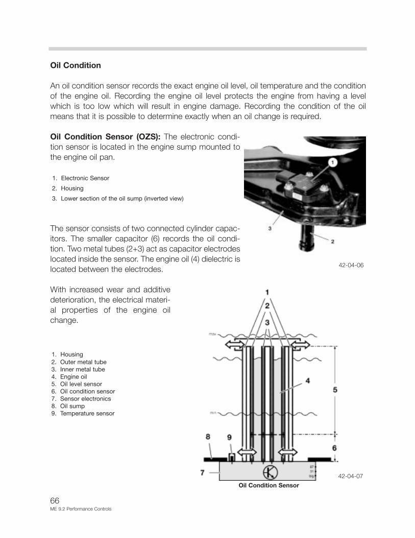
Oil Condition
An oil condition sensor records the exact engine oil level, oil temperature and the conditionof the engine oil. Recording the engine oil level protects the engine from having a levelwhich is too low which will result in engine damage. Recording the condition of the oilmeans that it is possible to determine exactly when an oil change is required.
Oil Condition Sensor (OZS): The electronic condi-tion sensor is located in the engine sump mounted tothe engine oil pan.
1. Electronic Sensor
2. Housing
3. Lower section of the oil sump (inverted view)
The sensor consists of two connected cylinder capac-itors. The smaller capacitor (6) records the oil condi-tion. Two metal tubes (2+3) act as capacitor electrodeslocated inside the sensor. The engine oil (4) dielectric islocated between the electrodes.
With increased wear and additivedeterioration, the electrical materi-al properties of the engine oilchange.
42-04-06
42-04-07
Oil Condition Sensor
1. Housing2. Outer metal tube3. Inner metal tube4. Engine oil5. Oil level sensor6. Oil condition sensor7. Sensor electronics8. Oil sump9. Temperature sensor

67ME 9.2 Performance Controls
The different electrical material properties of the engine oil (dielectric) change the capaci-tance of the oil condition sensor. This capacitance value is processed to a digital squarewave signal in the evaluation electronics (7) which is integrated in the sensor. This signal issent to the ECM over the BSD interface as a “statement” about the engine oil condition.The ECM processes this sensor value to calculate the next oil change service.
The engine oil level is determined in the upper section of the sensor (5). This part of thesensor is located on the top of the oil level in the oil sump. As the oil level lowers (dielec-tric), the capacitance of the sensor also changes. The sensor electronics process thiscapacitance value into a digital square wave signal which is also sent over the BSD inter-face to the ECM.
A platinum temperature sensor (9) is integrated at thebase of the oil condition sensor to measure the oil tem-perature. The engine oil level, oil temperature andengine oil condition are constantly recorded when volt-age is supplied (KL15). The oil condition sensor is sup-plied with voltage from the IVM.
The oil condition sensor electronics performs its owndiagnostics. A fault in the OEZS results in a corre-sponding error message that is transmitted over theBSD interface to the ECM for fault storage.
Electric Cooling Fan
The variable speed electric cooling fan is controlled by the ECM. The ECM uses a remotepower output final stage (mounted on the fan housing). The power output stage receivespower from the fuse (50 amp) junction located on the right inner fender of the engine com-partment (under the remote charging post). The electric fan is controlled by a pulse widthmodulated signal from the ECM.
The fan is activated based on the ECM calculation of:
• Coolant outlet temperature (monitored by the Outlet Temperature Sensor in the ther- mostat housing)
• Catalyst temperature • Vehicle speed• Battery voltage• Air Conditioning high side pressure (calculated by IHKA via a bus signal to the ECM)
42-04-08

68ME 9.2 Performance Controls
Alternator
Due to the high power capacity of 180 A, the alternator is cooled by the engine's coolingsystem to enhance heat dissipation. The brushless Bosch alternator is installed in an alu-minum housing which is mounted to the engine block. The exterior alternator walls are sur-rounded with circulated engine coolant. The function and design of the alternator is thesame as in the M62, with only minor modifications. The BSD interface (bit-serial data inter-face) for the ECM is new.
Regulation
The alternator can actively communicate with the ECMvia the BSD (bit-serial data interface). The alternatorconveys data to the ECM.
This is necessary to allow the ECM to adapt its calcu-lations and specific control to the alternator output.
The connection with the ECM makes it possible toalmost completely equalize the alternator load torque.This supports the engine idling speed control and thebattery load balance.
In addition, the ECM receives information from thePower Module about the battery's calculated temper-ature and charge status. This means that alternatoroutput can be adapted precisely to the temperatureand load status of the battery which increases the bat-tery service life.
42-04-09
42-04-08
Altenator
1. Watertight Housing2. Rotor3. Stator4. Seal

69ME 9.2 Performance Controls
The ECM takes on the following functions:
• Activation/deactivation of the alternator.
• Informing the alternator regulator of the nominal voltage value to be set.
• Controlling the alternator's response to load.
• Diagnosing the data line between the alternator and the ECM.
• Storing alternator fault codes.
• Activating the charge indicator lamp in the instrument cluster.
The charge indicator display strategy has not changed in comparison with the alternatorscurrently in use. Regulating the alternator output is particularly important when activatingValvetronic operating motors.
A temperature protection function is implemented in the voltage regulator. If the alternatoroverheats, the alternator voltage is reduced until an appropriate temperature has beenreached.
The ECM can recognize the following faults:
• Mechanical faults such as blockages or belt drive failure.
• Electrical faults such as exciter diode defects or over/under voltage caused by regula-tion defects.
• Connection defects between the ECM and the alternator.
Coil breaks and short-circuits cannot be recognized. The basic alternator function is inoperation even if the BSD interface fails.
Note: The alternator regulator voltage is influenced by the ECM - BSD interface. The bat-tery charge voltage can therefore be up to 15.5 V, depending on the battery temperature.If a battery charge voltage of up to 15.5 V is measured, the regulator is not faulty. A highcharge voltage indicates a low battery temperature.

70ME 9.2 Performance Controls
Electronic Box Cooling Fan
The E-box develops very high temperaturescaused by engine heat and the energy dissipat-ed by the control units. The ECM controls anelectric cooling fan in the base of the electronicbox to draw in cool air from the passenger com-partment.
Since electronic control modules need to oper-ate at a reduced temperature, the air tempera-ture in the E-box must be kept as low as possi-ble. Lower temperatures extend the life expec-tancy of electronic control modules.
Comfort Start
The comfort start makes easy engine starting possiblebecause the starter remains automatically activated until theengine is running (rpm signal). Security is enhanced by usingthe CAS Module with coded keys and the ignition starting but-ton (integral).
When starting to the engine, the CAS contains the data for the EWS code which is trans-ferred to the ECM. The transmission of EWS data between the CAS and the ECM is overthe data line D - EWS. Terminal R and terminal 15 is directed by the CAS for all electricalsystems. The CAS also activates KL15 WUP (Wake UP) for control modules on the PT-CAN.
When KL15 WUP is activated, the control modules change from the state of rest into theoperating condition. During the starting procedure, KL 50L for the comfort starting relay (inthe IVM) and KL 50E is switched to the ECM for the starting request. The ECM will activatea ground signal to the comfort starting relay to energize the starter motor.
The brake light switch is monitored by the ECM for the comfort start feature as well ascruise control. An engine start is possible only if the brake pedal is pressed. For safety rea-sons, the CAS monitors both signals of the brake light switch (the actual brake light switchand the brake light test switch).
The selector lever of automatic transmission must be in position P or N. The position of theselector lever is detected from the direct hardwire signal or via a CAN signal.
42-04-21
42-04-11

71ME 9.2 Performance Controls
Comfort Start - Block Diagram

72ME 9.2 Performance Controls
Actuation Time of Terminal 50: The monitored actuating times of terminal 50 protectsthe starter against overloading. The actuation times of terminal 50 are:
• A maximum of 21 seconds. A repetition is possible immediately.
• The actuation time is reduced for each repetition by 2 seconds until the minimum actuation time of 3 seconds is reached.
• If the start/stop button is pressed for longer than the preceding actuation time, the actuation time is increased by 2 seconds again (up to a maximum of 21 seconds).
Switching off the Engine: The vehicle engine is switched off when the vehicle is stoppedand the start/stop button is pressed. If the start/stop button is pressed for longer than 2seconds, the vehicle engine is switched off and then the key is automatically released andpushed out with spring pressure ("convenience off").
Incorrect Operation and "Emergency On": To ensure the safety of the vehicle in thecase of an accidental engine shutdown during driving, the "Emergency On" function isavailable. An engine shutdown during driving can be caused by accidentally pressing thestart/stop button (the button must be pressed for at least 1 second or 3 times consecu-tively).
The "Emergency On" function enables the starter to be actuated again without brake oper-ation at a vehicle speed above 5 km/h (3 mph). The "Emergency On" function also preventsterminal R from being switched off during driving.
Service Functions: When replacing the ECM and/or CAS Module, the following must becompleted:
The Service Function "DME/DDE - CAS alignment" in the DISplus. After the alignment thetwo modules are rigidly assigned to each other and the vehicle.
Note: It is not possible to exchange these control modules with another vehicle for testingpurposes.

73ME 9.2 Performance Controls
Cruise Control
The cruise control (FGR) is a function of the ECM and has multi-speed capability on theE65. This multi-speed function allows the driver to program and store multiple speed set-tings which can then be activated as required.
This means that speed settings such as 30, 50, or 65 mph can be selected directly at thetouch of a button without having to drive the vehicle precisely at that speed beforehand.This is a considerable added convenience. Those preset cruise control speeds are pro-grammed by the driver in advance and then activated when driving.
Speedometer in Instrument Cluster:
1. Preset speeds
2. Cruise control active:
illuminated pointer
3. Cruise control not active:
silhouette pointer
Briefly press/pull the lever to illuminate the cruise control mask in the speedometer. Thememory will accept and store up to 6 preset speeds. When the cruise control is not active,the silhouette pointer indicates the last speed at which it was activated.
When the cruise control is active, the illuminated pointer indicates the speed that is cur-rently being maintained. The cruise control can be activated at any speed from approxi-mately 20 mph upwards.
When the ignition is switched OFF, the cruise control is switched off at the same time.Moving the lever up/dn will deactivate the cruise control and delete the mask in thespeedometer. The cruise control function is overridden by braking, selecting transmissionsetting "N" or active DSC intervention.
1
2 3

74ME 9.2 Performance Controls
Cruise Control Lever: The cruise control isoperated by the left lower steering column lever.
When the lever is pressed forward to (but notbeyond) the detent, the current road speed isstored and maintained.
Flicking the lever forwards increases the vehicleroad speed by approx. 1 mph at a time. If thelever is pressed and held, the vehicle acceler-ates. When the lever is then released, the speedis stored and maintained.
When decelerating, flicking the lever backwards repeatedly reduces the vehicle road speedby approx. 1 mph at a time. When the multi-speed function is activated, the preset speedindicators on the speedometer can be hidden. This is done by pressing and holding thecruise control lever up or down for more than 3 seconds.
Programming/Deleting Preset Speeds
Programming of preset speeds should be performed while the vehicle is stationary withKL15 switched “on”. It is also possible to program the preset speeds while driving.However, altering the preset speed also alters the current speed being maintained.
To program a preset speed, the cruise control lever is pressed forwards or backwardsbeyond the detent. A pointer then appears on the speedometer that indicates the presetspeed. To increase the preset speed, the cruise control lever must be pressed forward tothe detent. To reduce the preset speed, the cruise control lever must be pulled backwardsto the detent.
To store the preset speed, the slide switch (in the end of the lever) must be pressed andheld in for at least 3 seconds. The stored preset speed is indicated by a pointer on thespeedometer. A preset speed is deleted by selecting it using the cruise control lever andthen pressing and holding the slide switch in for at least 3 seconds. The speed pointer thendisappears.
Note: The preset cruise control speeds are a Vehicle Memory function.
42-04-13

75ME 9.2 Performance Controls
Function Operated ByActivate cruise control accelerate/set Move lever forwards
Decelerate/set Move lever backwards
Activate multi-speed function Pressing lever forwards past detent
Select next higher preset speed Pressing lever forwards past detent
Select next lower preset speed Pressing lever backwards past detent
Cancel cruise control Move lever up/down
Recall/set/delete preset speeds Press slide switch inwardswhile cruise control active
Notes:

76ME 9.2 Performance Controls
Review Questions
1. Describe the Integrated Voltage Supply Module (IVM) for the Fuel Injectors and Ignition Coils:
2. List the three signal operations required to detect Valvetronic Positon.
3. Describe how the Electric Fuel Pump is activated.
4. What type of Ignition Coils are used in the N62?
5. Where is the Active Charcoal Canister and DM TL located?
6. What are the advantages of the Bosch LSU Planar Wideband Oxygen Sensors?
7. List the functions of the Oil Condition Sensor.
8. Explain the Comfort Start feature.
9. How are the Cruise Control preset speeds programmed and deleted?