Embed Size (px)
Citation preview

User’s guide
TA467 Insulation tester
www.picoauto.com

2 DO341-1
TA467 Insulation Tester User’s Guide
Copyright © 2020 Pico Technology Ltd. All rights reserved.
Contents1. Description ................................................................................................................................ 32. Appearance ............................................................................................................................... 33. Symbols and annunciators....................................................................................................... 44. Operating instructions .............................................................................................................. 54.1. Safety instructions .................................................................................................................... 54.2. Measurements and tests ......................................................................................................... 54.2.1. DC voltage measurements ....................................................................................................... 54.2.2. AC voltage measurements (frequency, duty cycle) ................................................................ 64.2.3. mV voltage measurements ...................................................................................................... 74.2.4. Resistance measurements ...................................................................................................... 74.2.5. DC current measurements ....................................................................................................... 84.2.6. AC current measurements (frequency, duty cycle) ................................................................ 94.2.7. Continuity check ..................................................................................................................... 104.2.8. Diode test ................................................................................................................................ 104.2.9. Capacitance measurements .................................................................................................. 114.2.10. Temperature measurements.................................................................................................. 114.2.11. Frequency (duty cycle) measurements (electronic) ............................................................. 124.2.12. % 4 - 20 mA measurements .................................................................................................. 124.2.13. Insulation resistance measurements .................................................................................... 134.3. Auto-ranging/manual range selection ................................................................................... 164.4. MAX/MIN ................................................................................................................................ 164.5. Relative mode ......................................................................................................................... 164.6. Display backlight ..................................................................................................................... 164.7. Hold ......................................................................................................................................... 174.8. Peak hold ................................................................................................................................. 174.9. Data storage ............................................................................................................................ 174.10. Data storage recall .................................................................................................................. 184.11. Clear all data ........................................................................................................................... 184.12. PC wireless communication ................................................................................................. 184.13. Sending stored data to the PC ............................................................................................... 184.14. SETUP (SET) ........................................................................................................................... 194.15. AC + DC ................................................................................................................................... 194.16. Low battery indication ............................................................................................................ 194.17. Maintenance ........................................................................................................................... 204.17.1. Battery installation .................................................................................................................. 204.18. Technicalspecifications ......................................................................................................... 21

3DO341-1
TA467 Insulation Tester User’s Guide
Copyright © 2020 Pico Technology Ltd. All rights reserved.
1. DescriptionThe TA467 Insulation tester is specially designed for vehicles with on-board high voltagesand conforms to EN61010 CAT III (1000 volts) and CAT IV (600 volts). The insulation test function allows testing of the insulation of the high voltage wires found on high-voltage vehicles. It can be used as a stand-alone device or linked wirelessly with a USB interface to a PC or laptop so you can have the results graphed, saved or printed. In addition to the insulation test, it can be used to test diodes and to measure AC/DC voltage, AC/DC current, resistance, capacitance, frequency (electrical and electronic), duty cycle, continuity and thermocouple temperature. It can store and recall data and features a waterproof, rugged design for heavy duty use.
2. Appearance
Controls and jacks
1. 40,000 count LCD display 9. mA, µA and Insulation - input jack
2. STORE, RECALL and < button 10. REL and + button
3. MAX/MIN and – button 11. HOLD, PeakHOLD and > button
4. RANGE and SETUP button 12. EXIT and AC+DC button
5. INSULATION TEST button 13. Backlight and USB button
6. MODE and LOCK button 14.V,Ω,,,,Hz%,Temp,andInsulation +inputjack
7. Function switch 15. COM input jack
8. 10 A input jack
Note: The tilt stand and battery compartment are on the rear of the unit.
1
4
3
2
56
7
8
915
14
1312
11
10

4 DO341-1
TA467 Insulation Tester User’s Guide
Copyright © 2020 Pico Technology Ltd. All rights reserved.
3. Symbols and annunciatorsContinuity NO. Serial number
Diode test S Second
Battery status SET Set up parameter
n Nano (10-9) (capacitance) AC + DC Alternating current + direct current
µ Micro (10-6) (amps, cap) TRMS True RMS
m Milli (10-3) (volts, amps) STO Store
A Amps RCL Recall
k Kilo (103) (ohms) AUTO Autorange
F Farads (capacitance) Backlight
M Mega (106) (ohms) PEAK Peak hold
Ω Ohms V Volts
Hz Hertz (frequency) REL Relative
% Percent (duty ratio) AUTO Autoranging
AC Alternating current HOLD Display hold
DC Direct current °C Degrees Celsius
°F Degrees Fahrenheit MIN Minimum
MAX Maximum RF icon

5DO341-1
TA467 Insulation Tester User’s Guide
Copyright © 2020 Pico Technology Ltd. All rights reserved.
4. Operating instructions4.1. Safety instructions
WARNING
Risk of electrocution. High-voltage circuits, both AC and DC, are very dangerous and should be measured with great care.
• Always turn the function switch to the OFF position when you finish using the insulation tester.
• If OL appears in the display during a measurement, the value exceeds the range you have selected and you need to change to a higher range.
Please refer to the complete safety information for this product, in the PicoScope® 4225A and 4425A Automotive oscilloscope and accessories Safety Guide, before you use it.
4.2. Measurements and tests4.2.1. DC voltage measurements
CAUTION
Do not measure DC voltages if a motor on the circuit is being switched ON or OFF. Large voltage surges may occur which can damage the unit.
1. Set the function switch to the V DC position.2. Insert the black test lead into the COM jack (negative). Insert
the red test lead into the V jack (positive).3. Touch the black test probe tip to the negative side of the
circuit and touch the red test probe tip to the positive side of the circuit.
4. Read the voltage in the display.

6 DO341-1
TA467 Insulation Tester User’s Guide
Copyright © 2020 Pico Technology Ltd. All rights reserved.
4.2.2. AC voltage measurements (frequency, duty cycle)WARNING
Risk of electrocution! The probe tips may not be long enough to reach the live parts inside some 240 V outlets for appliances, because the contacts are recessed deep in the outlets. As a result, the reading may show 0 volts when the outlet actually has a voltage on it. Make sure that the probe tips are touching the metal contacts inside the outlet before you assume that there is no voltage present.
CAUTION
Do not measure AC voltages if a motor on the circuit is being switched ON or OFF. Large voltage surges may occur which can damage the unit.
1. Set the function switch to the V AC position2. Insert the black test lead into the COM jack (negative). Insert the
red test lead into the V jack (positive). 3. Touch the black test probe tip to the neutral side of the circuit and
touch the red test probe tip to the hot side of the circuit. 4. Read the voltage in the main display and read the frequency in the
right auxiliary display.5. Press and hold the MODE button for two seconds to switch to Hz.6. Read the frequency in the main display.7. Press the MODE again to read the % of duty cycle in the main
display.8. Press EXIT9. Press and hold the AC + DC button for two seconds to switch to
AC + DC. 10. Test AC and DC TRUE RMS.

7DO341-1
TA467 Insulation Tester User’s Guide
Copyright © 2020 Pico Technology Ltd. All rights reserved.
4.2.3. mV voltage measurementsCAUTION
Do not measure mV voltages if a motor on the circuit is being switched ON or OFF. Large voltage surges may occur which can damage the unit.
1. Set the function switch to the mV position.2. Press the MODE button to indicate AC or DC OR while in AC
range press and hold the AC + DC button for two seconds to switch to AC + DC.
3. Insert the black test lead into the COM jack (negative). Insert the red test lead into the V jack (positive).
4. Touch the black test probe tip to the negative side of the circuit and touch the red test probe tip to the positive side of the circuit.
5. Read the mV voltage in the display.
4.2.4. Resistance measurementsWARNING
To avoid electric shock, disconnect all power to the unit under test and discharge all capacitors before you take any resistance measurements.
1. Set the function switch to the Ω position.2. Insert the black lead into the COM jack (negative). Insert the red
lead into the Ω jack (positive).3. Touch the test probe tips to the circuit or part you wish to check.
It is best to disconnect one side of the part you are testing to avoid interference from both sides of the circuit.
4. Read the resistance in the display.

8 DO341-1
TA467 Insulation Tester User’s Guide
Copyright © 2020 Pico Technology Ltd. All rights reserved.
4.2.5. DC current measurementsWARNING
Risk of electrocution! The probe tips may not be long enough to reach the live parts inside some 240 V outlets for appliances, because the contacts are recessed deep in the outlets. As a result, the reading may show 0 volts when the outlet actually has a voltage on it. Make sure that the probe tips are touching the metal contacts inside the outlet before you assume that there is no voltage present.
CAUTION
Do not capture 20 A current measurements for more than 30 seconds. Exceeding 30 seconds may cause damage to the unit and/or to the test leads.
1. Insert the black test lead into the COM jack (negative).2. Set the function switch to the required position and connect
the red test lead: a. For current measurements up to 4000 µA DC: Set the
function switch to the µA position and insert the red test lead into the µA mA jack.
b. For current measurements up to 400 mA DC: Set the function switch to the mA position and insert the red test lead into the µA mA jack.
c. For current measurements up to 20 A DC: Set the function switch to the 10A position and insert the red test lead into the 10A jack.
3. Press the MODE button to switch to DC on the display.4. Remove power from the circuit under test.5. Open up the circuit at the point where you want to measure the
current. 6. Touch the black test probe tip to the negative side of the circuit
and touch the red test probe tip to the positive side of the circuit.
7. Apply power to the circuit.8. Read the current in the display.

Copyright © 2020 Pico Technology Ltd. All rights reserved. 9DO341-1
TA466 Voltage Detector User’s Guide
4.2.6. AC current measurements (frequency, duty cycle)CAUTION
Do not capture 20 A current measurements for more than 30 seconds. Exceeding 30 seconds may cause damage to the unit and/or to the test leads.
1. Insert the black test lead into the COM jack (negative).2. Set the function switch to the required position and connect
the red test lead: a. For current measurements up to 4000 µA AC: Set the
function switch to the µA position and insert the red test lead into the µA mA jack.
b. For current measurements up to 400 mA AC: Set the function switch to the mA position and insert the red test lead into the µA mA jack.
c. For current measurements up to 20 A AC: Set the function switch to the 10A position and insert the red test lead into the 10A jack.
3. Press the MODE button to switch to AC on the display.4. Remove power from the circuit under test.5. Open up the circuit at the point where you want to measure
the current.6. Touch the black test probe tip to the neutral side of the circuit
and touch the red test probe tip to the hot side of the circuit.7. Apply power to the circuit.8. Read the current in the display. In the 10 A AC range, the right
auxiliary display will show the frequency.9. Press and hold the MODE button to switch to Hz. 10. Read the frequency in the display.11. Press the MODE button again to indicate %.12. Read the % duty cycle in the display.13. Press the EXIT button to return to current measurement14. Press the MODE button to select AC.15. Press and hold the AC + DC button for two seconds to switch
to AC + DC.16. Test AC and DC TRUE RMS.

10 DO341-1
TA467 Insulation Tester User’s Guide
Copyright © 2020 Pico Technology Ltd. All rights reserved.
4.2.7. Continuity checkWARNING
To avoid electric shock, never measure continuity on circuits or wires that have voltage on them.
1. Set the function switch to the Ω position.2. Insert the black lead into the COM jack (negative). Insert the red
lead into the Ω jack (positive).3. Press the MODE button to switch to and Ω on the display.4. Touch the test probe tips to the circuit or wire you wish to check.5. Iftheresistanceislessthan35Ω,theaudiblesignalwillsound.If
the circuit is open, OL will display.
4.2.8. Diode test1. Set the function switch to the Ω CAP position.2. Insert the black test lead into the COM jack (negative)andthe
red test lead into the V jack (positive).3. Press the MODE button to switch to and V on the display.4. Touch the test probes to the circuit on either side of the
diode under test. Forward voltage will typically indicate 0.400 to 0.700 V.ReversevoltagewillindicateOL. Shorted deviceswillindicatenear0 VandopendeviceswillindicateOL in both polarities.

11DO341-1
TA467 Insulation Tester User’s Guide
Copyright © 2020 Pico Technology Ltd. All rights reserved.
4.2.9. Capacitance measurementsWARNING
To avoid electric shock, disconnect all power to the unit under test and discharge all capacitors before you take any capacitance measurements.
1. Set the function switch to the CAP position.2. Insert the black test lead into the COM jack(negative)andthe
red test lead into the V jack (positive).3. Press the MODE button to switch to nF.4. Touch the test probes to the circuit on either side of the the
capacitor you are testing.5. Read the capacitance value in the display.
4.2.10. Temperature measurements
1. Set the function switch to the Temp position2. Connect the temperature probe to the input jacks on the unit
(make sure that you observe the correct polarity).3. Press the MODE button to switch to °F or °C.4. Touch the temperature probe tip to the part that you
wish to measure the temperature of. Keep the probe touchingthepartundertestuntilthereadingstabilizes(about 30 seconds).
5. Read the temperature in the display.
Note: The temperature probe is fitted with a K-Type mini connector. The tool is supplied with a mini to banana adaptor to connect to the input jacks on the unit.

12 DO341-1
TA467 Insulation Tester User’s Guide
Copyright © 2020 Pico Technology Ltd. All rights reserved.
4.2.11. Frequency (duty cycle) measurements (electronic)
1. Set the function switch to the Hz% position.2. Insert the black test lead into the COM jack (negative) and the
red test lead into the Hz% jack (positive).3. Touch the test probes to the circuit under test.4. Read the frequency on the display.5. Press the MODE button to switch to %.6. Read the % duty cycle in the display.
4.2.12. % 4 - 20 mA measurements 1. Insert the black test lead into the COM jack (negative).2. Insert the red test lead into the µA mA jack.3. Set the function switch to the 4-20mA% position.4. Remove power from the circuit under test.5. Open up the circuit at the point where you want to measure the
current. 6. Touch the black test probe tip to the negative side of the circuit and
touch the red test probe tip to the positive side of the circuit.7. Apply power to the circuit.8. The loop current will be displayed as a % with 0 mA=-25%, 4
mA=0%, 20 mA=100% and 24 mA=125%.

13DO341-1
TA467 Insulation Tester User’s Guide
Copyright © 2020 Pico Technology Ltd. All rights reserved.
4.2.13. Insulation resistance measurementsWARNING
Risk of electric shock during testing. The Insulation tester applies a potential difference (1000 V DC maximum) across its probe tips during an insulation resistance test. If the LOCK function is active, this voltage will be present at all times.
WARNING
Insulation testing a powered-up high-voltage system may cause death and damage to equipment. Safely power down the high-voltage system according to the manufacturer’s instructions and check for the absence of high-voltage prior to insulation resistance testing.
1. Set the function switch to the Insulation position. Note the voltages in the top left corner on the display. Press the RANGE button to switch between the available test voltages and select a suitable voltage range for your application.
2. Connect the black test lead to the Insulation - jack (negative) and connect the red test lead to the Insulation + jack (positive).
3. Connect the two test leads to the circuit you want to test.4. You can now continue the test in two different ways:
a. Without the LOCK function i. Push down and hold the INSULATION TEST button ii. If the insulation detects a potential difference between the probe tips of less than 30 V
(AC or DC), it will: 1. Display the lightning symbol while the test voltage is applied 2. Display the insulation resistance (in megaohms) 3. Display the achieved test voltage (in VDC) in the top right ocorner of the display 4. Indicate the insulation resistance using the analog bar graph 5. Soundafrequentbuzzerwarning
Otherwise, the insulation tester will not apply a test voltage and will display both > 30 V andaflashinglightningsymbolandsoundabuzzerwarning.
iii. Release the INSULATION TEST button
iv. The insulation resistance and achieved test voltage will continue to be displayed for approximately 20 seconds, although you can push and release the EXIT button within this period to clear the display and discharge any residual test voltage from the tester.

14 DO341-1
TA467 Insulation Tester User’s Guide
Copyright © 2020 Pico Technology Ltd. All rights reserved.
b. With the LOCK function:
i. Push down and hold the LOCKbuttonfortwoseconds.Abuzzerwillsoundtwicetoconfirmithasbeenactivated.
ii. Push and release the INSULATION TEST button iii. If the insulation detects a potential difference between the probe tips of less than 30 V
(AC or DC), it will:
1. Display the lightning symbol whilst the test voltage is applied. 2. Display the insulation resistance (in megaohms). 3. Display the achieved test voltage (in VDC) in the display top right corner. 4. Indicate insulation resistance using the analog bar graph. 5. Soundafrequentbuzzerwarning.
Otherwise, the Insulation tester will not apply a test voltage and will display both > 30 V andaflashinglightningsymbolandsoundabuzzerwarning.
iv. Push the EXIT button to stop applying the test voltage, discharge any residual test voltage from the tester, and clear the insulation resistance and the achieved test voltage from the display.
5. Rotate the function switch to OFF to exit the test. This discharges any remaining insulation test voltage through an internal switch, which will take approximately two seconds.
15DO341-1
TA467 Insulation Tester User’s Guide
Copyright © 2020 Pico Technology Ltd. All rights reserved.
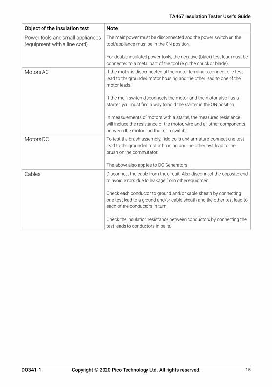
Object of the insulation test Note
Power tools and small appliances (equipment with a line cord)
The main power must be disconnected and the power switch on the tool/appliance must be in the ON position.
For double insulated power tools, the negative (black) test lead must be connected to a metal part of the tool (e.g. the chuck or blade).
Motors AC If the motor is disconnected at the motor terminals, connect one test lead to the grounded motor housing and the other lead to one of the motor leads.
If the main switch disconnects the motor, and the motor also has a starter, you must find a way to hold the starter in the ON position.
In measurements of motors with a starter, the measured resistance will include the resistance of the motor, wire and all other components between the motor and the main switch.
Motors DC To test the brush assembly, field coils and armature, connect one test lead to the grounded motor housing and the other test lead to the brush on the commutator.
The above also applies to DC Generators.
Cables Disconnect the cable from the circuit. Also disconnect the opposite end to avoid errors due to leakage from other equipment.
Check each conductor to ground and/or cable sheath by connecting one test lead to a ground and/or cable sheath and the other test lead to each of the conductors in turn
Check the insulation resistance between conductors by connecting the test leads to conductors in pairs.

16 DO341-1
TA467 Insulation Tester User’s Guide
Copyright © 2020 Pico Technology Ltd. All rights reserved.
4.3. Auto-ranging/manual range selectionWhen the insulation tester is first turned on, it automatically goes into Autoranging. This selects the best range for the measurements being made, which is generally the best mode for most measurements. For measurement situations requiring a manual range selection, perform the following:
1. Press the RANGE button once. The AUTO display indicator will turn off. 2. Press the RANGE buttonagaintogothroughtheavailablerangesuntilyoufindtherangeyou
want to select.3. To exit the manual ranging mode and return to Autoranging, press EXIT.
Note: Manual ranging does not apply for the temperature functions.
4.4. MAX/MINPress the MAX/MIN button to activate the MAX/MIN recording mode. The MAX icon will appear in the display. The left auxiliary display will hold the maximum reading and will update only when a new max occurs. The MIN icon will appear in the display. The right auxiliary display will hold the minimum reading and will update only when a new min occurs. To exit MAX/MIN mode press EXIT.
4.5. Relative modeThe relative measurement feature allows you to make measurements relative to a stored reference value. A reference voltage, current, etc. can be stored and you can make measurements comparison to that value. The displayed value is the difference between the reference value and the measured value.
Note: Relative mode does not operate in the 4-20 mA function.
1. Perform the required measurement as described in the appropriate operating instructions. 2. Press the REL button to store the reading in the display and the REL indicator will appear on the
display. a. The left auxiliary display will show the margin of the initial value and the current value. The
right auxiliary display will show the initial reading. The main display will show the reading after REL TEST.
3. Press the EXIT button to exit the relative mode.
4.6. Display backlightPress the key to turn the backlight on. The backlight will automatically turn off after the set time (see page 19 to learn how to change this setting). Press the button to exit the backlight-on mode.

17DO341-1
TA467 Insulation Tester User’s Guide
Copyright © 2020 Pico Technology Ltd. All rights reserved.
4.7. HoldTheholdfunctionfreezesthereadinginthedisplay.PresstheHOLD key to activate or to exit the HOLD function.
4.8. Peak holdThe peak hold function captures the peak AC voltage or peak AC and DC current. The unit can capture negative or positive peaks as fast as 1 millisecond in duration. Press the PEAK button, PEAK and MAX will display in the left auxiliary display. MIN will display in right auxiliary display. The unit will update the display each time a lower negative peak occurs. Press the EXIT button to exit the PEAK HOLD mode.
Note: The auto power-off feature is automatically disabled in this mode.
4.9. Data storageSTORE function:While being in your chosen testing mode, press the STORE button one time to enter the STORE function and the setup for the recording interval time function.
The upper left corner shows 0000 S, the recording interval time. Use the + and - buttons to select. The range is 0 to 255 seconds.
When the recording interval time is set to 0000 S, press the STORE button to change into manual recording. Press the STORE button again to record. When the recording interval time is set to 1 to 255 S, press the STORE button to start recording automatically from 0000. Recording time is shown in the upper left corner, data is shown in the upper right corner. Note: The time display is limited to four digits. To exit the STORE function, press the EXIT button.
For storing insulation measurements:When the recording interval time is set to 0000 S, press the STORE button to change into manual recording. While you perform the insultation test press the STORE button to record the displayed value.
When the recording interval time is set to 1 to 255 S, press the STORE button to automatically start recording the displayed value at the selected interval while you perform the test. The number of stored recordings is shown in the upper left corner, data is shown in the upper right corner. Note: The time display is limited to four digits. To exit the STORE function, press the EXIT button.

18 DO341-1
TA467 Insulation Tester User’s Guide
Copyright © 2020 Pico Technology Ltd. All rights reserved.
4.10. Data storage recall1. Switch on the meter.2. Press and hold the STORE button for two seconds to enter into the RECALL function. The upper
left corner will show XXXX, which is the serial number for the current storage. The upper right corner will show XXXX, which is how much of the storage that is currently in use.
3. Use the + and - buttons to select the required serial number XXXX in the upper left corner and record the data in the upper right corner.
4. To exit the RECALL function, press the EXIT button.
4.11. Clear all data1. From the OFF position, press and hold the RANGE button while turning the function switch to
any position. 2. Release the RANGE button. The memory has been cleared.
4.12. PC wireless communication 1. Install and launch the PC software. 2. Switch on the meter.3. Press and hold the USB button for two seconds to enter RF wireless transmit mode. The RF
icon will appear on the display.4. When communication is established, the RF icon on the display will blink and the LED indicator
on the receiver will blink. 5. The data will be displayed on the PC screen (plotted on the graph and inserted in the data list)
once every second.6. Press and hold the USB button for two seconds to exit the RF wireless transmit mode. 7. RefertotheHELPfileinthesoftwareformoredetails.
4.13. Sending stored data to the PC1. Launch the PC software.2. Switch on the meter.3. Press and hold the STORE button for two seconds to enter data RECALL function.4. PressandholdtheHOLDbuttonfortwoseconds.TheRFtransmiticonwillflashwhilethe
stored data is sent to the PC.
Note: The time stamp for the transferred data is the time it was transferred, not captured. Note: Refer to the HELP file included in the software for in-depth software instructions.

19DO341-1
TA467 Insulation Tester User’s Guide
Copyright © 2020 Pico Technology Ltd. All rights reserved.
4.14. SETUP (SET)This function allows you to configure the meter and decide on the following settings:
The settings includes (in sequence): a. upperlimitbuzzeralarm,theunitwillsoundthealarm(“beep”)ifthemeasuredvalueis
greater than the high limit. b. lowerlimitbuzzeralarm,theunitwillsoundthealarm(“beep”)ifthemeasuredvalueis
lower than the low limit. c. auto power-off time d. turn off sound e. backlight time
Press and hold the SETUP button for two seconds to enter the settings menu. The screen will display SET on the left display, OFF on the main display and High on the right display. This is the firstavailablesetting,theupperlimitbuzzeralarm.
To change this setting, press the > button to cycle through the digit placement. Use the + and - buttonstoselectavalue.Pleasenotethatthissettingdoesnotusedecimals.
Press the <buttontocanceltheupperlimitbuzzer(OFFintheprimarydisplay).
Press the SETUP button to save this setting and move to the next setting in the menu.
Note: In the last three settings you can only use the + and < button to alter the settings.
Note: If you press the EXIT button to cancel while in the settings, you will exit from the menu without saving any updated settings.
4.15. AC + DCIn any of the following measuring modes, V AC, mV (AC), 10 A (AC), mA (AC), µA (AC), you can press and hold the EXIT button for two seconds to enter AC + DC testing. The procedure is the same as with AC measurement. The display will show the AC+DC icon. Press the EXIT button to exit the mode.
4.16. Low battery indicationWhen the icon appears alone in the display, you need to replace the battery.

20 DO341-1
TA467 Insulation Tester User’s Guide
Copyright © 2020 Pico Technology Ltd. All rights reserved.
4.17. MaintenanceWARNING
To avoid electric shock, disconnect the test leads from any source of voltage before you remove the battery cover, the batteries and the rear cover.
WARNING
To avoid electric shock, do not operate your insulation tester until the rear cover and battery cover are in place and fastened securely.
This insulation tester is designed to provide years of dependable service if the following care instructions are performed.
1. Keep the unit dry. If it gets wet, dry it immediately.2. Use and store the unit in normal temperatures. Temperature extremes can shorten the life of the
electronic parts and distort or melt plastic parts. 3. Handle the unit gently and carefully. Dropping it can damage the electronic parts or the case.4. Keep the unit clean. Wipe the case occasionally with a damp cloth. DO NOT use chemicals,
cleaning solvents or detergents. 5. Useonlyfreshbatteriesoftherecommendedsizeandtype.Removeoldorweakbatteriesso
they do not leak and damage the unit.6. If the unit is to be stored for a long period of time, the batteries should be removed to prevent
damage to it.
4.17.1. Battery installation1. Turn the power off and disconnect the test leads from the unit.2. Lift the stand to access the battery cover. 3. Remove the battery cover by removing four screws (requiring a Phillips head screwdriver).4. Insert six AA batteries into the battery holder. Observe the correct polarity.5. Put the battery cover back in place and secure with the screws.
Note: If your insulation tester does not work properly, check the fuses and batteries to make sure that they are still good and that they are properly installed.
Replacing the fuses1. Turn the power off and disconnect the test leads from the unit.2. Lift the stand to access the battery cover. 3. Remove the battery cover by removing four screws (requiring a Phillips head screwdriver).4. Remove the six AA batteries.5. Remove the rear cover by removing six screws (requiring a Phillips screwdriver) and carefully
separating it from the front cover. Be aware of the supply wires, you do not want to pull them too hard. Both fuses should now be easily accessible.
6. Carefully remove the old fuses and install the new fuses. a. Alwaysuseafuseofthepropersizeandvalue(0.5A/1000Vfastblowforthe400mA
range [SIBA 70-172-40], 10 A/1000 V fast blow for the 20 A range [SIBA 50-199-06]).7. Put the rear cover, batteries and battery cover back in place and secure with the designated
screws. Make sure you do not trap the supply wires when you put the rear cover back on.

21DO341-1
TA467 Insulation Tester User’s Guide
Copyright © 2020 Pico Technology Ltd. All rights reserved.
4.18. Technical specificationsNote:Accuracyspecificationsconsistoftwoelements:
• (% reading) - This is the accuracy of the measurement circuit.• (+ digits) - This is the accuracy of the analog to digital converter.
Function Range Resolution AccuracyDC voltage 400 mV 0.01 mV ± (0.06% reading + 4 digits)
4 V 0.0001 V40 V 0.001 V400 V 0.01 V1000 V 0.1 V ± (0.1% reading + 5 digits)
AC voltage 50 to 1000 Hz400 mV 0.1 mV ± (1.0% reading + 7 digits)4 V 0.001 V40 V 0.01 V ± (1.0% reading + 5 digits)400 V 0.1 V1000 V 1 V
AC + DC voltage 400 mV 0.1 mV ± (1.0% reading + 7 digits) (50/60 Hz)4 V 0.001 V
40 V 0.01 V400 V 0.1 V1000 V 1 VAll AC voltage ranges are specified from 5% of range to 100% of range.
DC current 400 µA 0.01 µA ± (1.0% reading + 3 digits)
4000 µA 0.1 µA40 mA 0.001 mA400 mA 0.01 mA10 A 0.001 A(20 A: 30 seconds max with reduced accuracy)
AC current (AC+DC)
50 to 1000 Hz400 µA 0.1 µA ± (1.5% reading + 7 digits)
4000 µA 1 µA40 mA 0.01 mA400 mA 0.1 mA10 A 0.01 A
AC+DC current 400 µA 0.1 µA ± (1.5% reading + 7 digits)4000 µA 1 µA40 mA 0.01 mA400 mA 0.1 mA10 A 0.01 A(20 A: 30 seconds max with reduced accuracy)All AC current ranges are specified from 5% of range to 100% of range.

22 DO341-1
TA467 Insulation Tester User’s Guide
Copyright © 2020 Pico Technology Ltd. All rights reserved.
Note: Accuracy is stated at 65°F to 83°F (18°C to 28°C) and less than 75% RH.AC accuracy depends on the purity of the sine wave. The error generally increases ±(2% reading + 2% full scale) for other waveforms with a crest factor of less than 3.0.
Function Range Resolution Accuracy
Resistance 400Ω 0.01Ω ± (0.3% reading + 9 digits)
4kΩ 0.0001kΩ ± (0.3% reading + 4 digits)
40kΩ 0.001kΩ
400kΩ 0.01kΩ
4MΩ 0.001MΩ
40MΩ 0.001MΩ ± (2.0% reading + 10 digits)
Capacitance 40 nF 0.001 nF ± (3.5% reading + 40 digits)
400 nF 0.01 nF
4 µF 0.0001 µF ± (3.5% reading + 10 digits)
40 µF 0.001 µF
400 µF 0.01 µF
4000 µF 0.1 µF ± (5.0% reading + 10 digits)
40 mF 0.001 mF
Frequency (electronic)
40Hz 0.001Hz ± (0.1% reading + 1 digits)
400Hz 0.01Hz
4kHz 0.0001kHz
40kHz 0.001kHz
400kHz 0.01kHz
4MHz 0.0001MHz
40MHz 0.001MHz
100MHz 0.01MHz Not specified
Sensitivity:0.8VRMSmin.@20%to80%dutycycleand<100kHz;5VRMSmin@20%to80%dutycycleand>100kHz.
Frequency (electrical)
40.00Hz-10kHz 0.01Hz-0.001kHz ± (0.5% reading)
Sensitivity: 1 V RMS
Duty cycle 0.1 to 99.90% 0.01% ± (1.2% reading + 2 digits)
Pulsewidth:100µs-100ms,Frequency:5Hzto150kHz
Temp(type-K)
-50 to 1000 °C- 58 to 1832 °F
0.1 °C0.1 °F
± (1.0% reading + 2.5 °C)± (1.0% reading + 4.5 °F)
4-20 mA% -25 to 125% 0.1 °F ± 50 digits
0 mA = -25%, 4 mA = 0%, 20 mA = 100%, 24 mA = 125%

23DO341-1
TA467 Insulation Tester User’s Guide
Copyright © 2020 Pico Technology Ltd. All rights reserved.
Megohms table
Terminal voltage
Range Resolution Accuracy Test current Short circuit current
125 V (0% ~ +10%)
0.125 ~ 4.000MΩ
0.001MΩ ±(2% + 10) 1 mA @ load 125kΩ
≤1mA
4.001 ~ 40.00MΩ
0.01MΩ ±(2% + 10)
40.01 ~ 400.0MΩ
0.1MΩ ±(4% + 5)
400.1 ~ 4000MΩ
1MΩ ±(5% + 5)
250 V (0% ~ +0%)
0.250 ~ 4.000MΩ
0.001MΩ ±(2% + 10) 1 mA @ load 250kΩ
≤1mA
4.001 ~ 40.00MΩ
0.01MΩ ±(2% + 10)
40.01 ~ 400.0MΩ
0.1MΩ ±(3% + 5)
400.1 ~ 4.000MΩ
1MΩ ±(4% + 5)
500 V (0% ~ +10%)
0.500 ~ 4.000MΩ
0.001MΩ ±(2% + 10) 1 mA @ load 500kΩ
≤1mA
4.001 ~ 40.00MΩ
0.01MΩ ±(2% + 10)
40.01 ~ 400.0MΩ
0.1MΩ ±(2% + 5)
400.1 ~ 4000MΩ
1MΩ ±(4% + 5)
1000 V (0% ~ +10%)
1.000 ~ 4.000MΩ
0.001MΩ ±(3% + 10) 1 mA @ load 1MΩ
≤1mA
4.001 ~ 40.00MΩ
0.01MΩ ±(2% + 10)
40.01 ~ 400.0MΩ
0.1MΩ ±(2% + 5)
400.1 ~ 4000MΩ
1MΩ ±(4% + 5)

24 DO341-1
TA467 Insulation Tester User’s Guide
Copyright © 2020 Pico Technology Ltd. All rights reserved.
www.picoauto.com
United Kingdom headquarters North America regional office Germany regional office
Pico TechnologyJames House Colmworth Business Park St. Neots Cambridgeshire PE19 8YPUnited Kingdom
Pico Technology320 N Glenwood Blvd Tyler TX 75702United States
Pico Technology GmbHIhm Rehwinkel 6 30827 Garbsen Germany
Tel: +44 (0) 1480 396395 Email: [email protected]
Tel: +1 800 591 2796 Email: [email protected]
Tel: +49 (0) 5131 907 6290 Email: [email protected]
Specifications
Storage capacity 2000 measurements
Enclosure Double-molded, IP67 waterproof
Shock (drop test) 6.5 feet (2 meters)
Diode test Test current of 0.9 mA maximum, open circuit voltage 2.8 V DC typical
Continuity check Audible signal will sound if the resistance is less than 35 Ω (approximately), test current < 0.35 mA.
PEAK Captures peaks > 1 ms
Temperature sensor Requires type K thermocouple
Input impedance >10 MΩ VDC and >9 MΩ V AC
AC response True RMS
AC True RMS The term stands for “Root-Mean-Square”, which represents the method of calculation of the voltage or current value. Average responding multimeters are calibrated to read correctly only on sine waves and they will read inaccurately on non-sine wave or distorted signals. True RMS meters read accurately on either type of signal.
AC V bandwidth 50 Hz to 1000 Hz
Crest factor ≤ 3 at full scale up to 500 V, decreasing linearly to ≤ 1.5 at 1000 V.
Display 40,000 count backlit liquid crystal with bargraph
Overrange indication “OL” is displayed
Auto power off 15 minutes (approximately) with disable feature
Polarity Automatic (no indication for positive); minus (-) sign for negative
Measurement rate 2 times per second, nominal
Low battery indication is displayed if the battery voltage drops below operating voltage.
Battery 1 x 9 V, NEDA 1604, 6F22, 006P
Fuses mA, µA ranges; 0.5 A/1000 V ceramic fast
Safety See the PicoScope® 4225A and 4425A automotive oscilloscope and accessories Safety Guide for the complete safety information.


![User's Model MY40 Insulation Resistance Tester [ …Insulation Resistance Tester [ Operation Manual ] This manual describes the specifications and handling precautions of the insulation](https://img.dokumen.tips/doc/110x75/5e58e655eb65b66d2954e0fb/users-model-my40-insulation-resistance-tester-insulation-resistance-tester-.jpg)