Embed Size (px)
Citation preview

T800, TB7100, TB8100 base stationsTA703 Change Over Module Service Manual
M703-01-0004 · Issue 4 · June 2014

2 TA703-xx-xxxx Change Over Module Service Manual © Tait Limited June 2014
Contact InformationTait Communications Corporate Head OfficeTait Limited P.O. Box 1645 Christchurch New ZealandFor the address and telephone number of regional offices, refer to our website: www.taitradio.com
Copyright and TrademarksAll information contained in this document is the property of Tait Limited. All rights reserved. This document may not, in whole or in part, be copied, photocopied, reproduced, translated, stored, or reduced to any electronic medium or machine-readable form, without prior written permission from Tait Limited.The word TAIT and the TAIT logo are trademarks of Tait Limited.All trade names referenced are the service mark, trademark or registered trademark of the respective manufacturers.
DisclaimerThere are no warranties extended or granted by this document. Tait Limited accepts no responsibility for damage arising from use of the information contained in the document or of the equipment and software it describes. It is the responsibility of the user to ensure that use of such information, equipment and software complies with the laws, rules and regulations of the applicable jurisdictions.
Enquiries and CommentsIf you have any enquiries regarding this document, or any comments, suggestions and notifications of errors, please contact your regional Tait office.
Updates of Manual and EquipmentIn the interests of improving the performance, reliability or servicing of the equipment, Tait Limited reserves the right to update the equipment or this document or both without prior notice.
Intellectual Property RightsThis product may also be made under license under one or more of the following U.S. Patents: 5,146,497, 5,148,482, 5,164,986, 5,185,795, 5,185,796, 5,271,017, 5,377,229 and 5,502,767. The AMBE+2™ voice coding Technology embodied in this product is protected by intellectual property rights including patent rights, copyrights and trade secrets of Digital Voice Systems, Inc. This voice coding Technology is licensed solely for use within this Communications Equipment. The user of this Technology is explicitly prohibited from attempting to decompile, reverse engineer, or disassemble the Object Code, or in any other way convert the Object Code into a human-readable form. Protected by U.S. Patents 5,870,405, 5,826,222, 5,754,974, 5,701,390, 5,715,365, 5,649,050, 5,630,011, 5,581,656, 5,517,511, 5,491,772, 5,247,579, 5,226,084 and 5,195,166.
Environmental ResponsibilitiesTait Limited is an environmentally responsible company which supports waste minimization, material recovery and restrictions in the use of hazardous materials.
The European Union’s Waste Electrical and Electronic Equipment (WEEE) Directive requires that this product be disposed of separately from the general waste stream when its service life is over. For more information about how to dispose of your unwanted Tait product, visit the Tait WEEE website at www.taitradio.com/weee. Please be environmentally responsible and dispose through the original supplier, or contact Tait Limited.Tait Limited also complies with the Restriction of the Use of Certain Hazardous Substances in Electrical and Electronic Equipment (RoHS) Directive in the European Union.In China, we comply with the Measures for Administration of the Pollution Control of Electronic Information Products. We will comply with environmental requirements in other markets as they are introduced.
TA703-xx-xxxx Change Over Module Service Manual Preface 3© Tait Limited June 2014
Preface
Scope of ManualThis document contains information about the operation and functions of the TA703-xx-xxxx Change Over Module. This is a T800-based product but can be used with TB7100 and TB8100 equipment. Differences are described within the manual.
Document Conventions“File > Open” means “click File on the menu bar, then click Open on the list of commands that pops up”. “Monitor > Module Details > Reciter” means “click the Monitor icon on the toolbar, then in the navigation pane find the Module Details group, and select Reciter from it”.
Within this manual, four types of alerts are given to the reader. The following paragraphs illustrate each type of alert and its associated symbol.
Warning This alert is used when there is a hazardous situation which, if not avoided, could result in death or serious injury.
Caution This alert is used when there is a hazardous situation which, if not avoided, could result in minor or moderate injury.
Notice This alert is used to highlight information that is required to ensure procedures are performed correctly. Incorrectly performed pro-cedures could result in equipment damage or malfunction.
This icon is used to draw your attention to information that may improve your understanding of the equipment or procedure.
Associated DocumentationThis manual should be read in conjunction with the following documents. Updates are made available on the Tait support web. Print copies of the documentation are available on request.■ TB8100 base station Service Manual (MBA-00016-xx)■ TB7100 base station Service Manual (MBB-00005-xx)■ T800 series II Service Manual (M800-00-xxx)
Technical notes are published from time to time to describe applications for Tait products, to provide technical details not included in manuals, and to offer solutions for any problems that arise. Look for new or updated
4 Preface TA703-xx-xxxx Change Over Module Service Manual © Tait Limited June 2014
technical notes on Tait’s technical support web site. Updates may also be published on the Tait support web site.
Publication Record
Abbreviations
Issue Publication Date Description
00 January 2001 First release
01 July 2003 Update
02 June 2005 Update
03 September 2005 Update
04 June 2014 Generalise to T800, TB7100 and TB8100 base stations.
Abbreviation Description
RR Remote Reset. In earlier versions this signal was named Remote Alarm Clear
RS Remote Select. This signal was known as Remote Tx or Tx Select
RAC Remote Alarm Clear: superseded by RR
RTS Remote Transmit Select: superseded by RS
FWD PWR Forward Power meters signal from external monitor module or from the base station transmitter. Typical T858 delivers 5V for output power of 50Watt
REV PWR Reverse Power meter signal from external monitor module or from the base station transmitter
RSSI Receiver Signal Strength Indicator, an analog signal from receiver that indicates how strong the incoming RF signal is at the receiver antenna port. In a UHF receiver this is about 10dB per Volt, relative to 2V at -110dBm.

TA703-xx-xxxx Change Over Module Service Manual 5© Tait Limited June 2014
Contents
1 Introduction . . . . . . . . . . . . . . . . . . . . . . . . . . . . . . . . . . . . . . . . . . . . . . . . . . . . . . . . . . . . . 91.1 Overview . . . . . . . . . . . . . . . . . . . . . . . . . . . . . . . . . . . . . . . . . . . . . . . . . . . . . . . . . . . . 91.2 Minimum system requirements . . . . . . . . . . . . . . . . . . . . . . . . . . . . . . . . . . . . . . . . . . 10
1.2.1 Receiver with RSSI fitted . . . . . . . . . . . . . . . . . . . . . . . . . . . . . . . . . . . . . . . . 101.2.2 Transmitter . . . . . . . . . . . . . . . . . . . . . . . . . . . . . . . . . . . . . . . . . . . . . . . . . . . 101.2.3 Limitations . . . . . . . . . . . . . . . . . . . . . . . . . . . . . . . . . . . . . . . . . . . . . . . . . . . 10
1.3 System Configuration . . . . . . . . . . . . . . . . . . . . . . . . . . . . . . . . . . . . . . . . . . . . . . . . . 111.4 Variants . . . . . . . . . . . . . . . . . . . . . . . . . . . . . . . . . . . . . . . . . . . . . . . . . . . . . . . . . . . . 12
1.4.1 Change Over Module Variants . . . . . . . . . . . . . . . . . . . . . . . . . . . . . . . . . . . . 121.4.2 System Variants . . . . . . . . . . . . . . . . . . . . . . . . . . . . . . . . . . . . . . . . . . . . . . . 13
1.5 Specifications 14
1.6 Operating Modes . . . . . . . . . . . . . . . . . . . . . . . . . . . . . . . . . . . . . . . . . . . . . . . . . . . . . 151.7 Hardware Description . . . . . . . . . . . . . . . . . . . . . . . . . . . . . . . . . . . . . . . . . . . . . . . . . 17
1.7.1 General . . . . . . . . . . . . . . . . . . . . . . . . . . . . . . . . . . . . . . . . . . . . . . . . . . . . . . 171.7.2 Front Panel . . . . . . . . . . . . . . . . . . . . . . . . . . . . . . . . . . . . . . . . . . . . . . . . . . . 181.7.3 Rear Panel . . . . . . . . . . . . . . . . . . . . . . . . . . . . . . . . . . . . . . . . . . . . . . . . . . . . 181.7.4 Mechanical Parts List . . . . . . . . . . . . . . . . . . . . . . . . . . . . . . . . . . . . . . . . . . . 19
2 Setup and Installation . . . . . . . . . . . . . . . . . . . . . . . . . . . . . . . . . . . . . . . . . . . . . . . . . . . . 212.1 Internal Setup . . . . . . . . . . . . . . . . . . . . . . . . . . . . . . . . . . . . . . . . . . . . . . . . . . . . . . . 21
2.1.1 Mode Select . . . . . . . . . . . . . . . . . . . . . . . . . . . . . . . . . . . . . . . . . . . . . . . . . . 212.1.2 Repeater Mode Versus Base Station Mode . . . . . . . . . . . . . . . . . . . . . . . . . . 212.1.3 Forward and Reverse Power Measurements. . . . . . . . . . . . . . . . . . . . . . . . . . 212.1.4 Single External Power Monitor . . . . . . . . . . . . . . . . . . . . . . . . . . . . . . . . . . . 222.1.5 Alarm Outputs. . . . . . . . . . . . . . . . . . . . . . . . . . . . . . . . . . . . . . . . . . . . . . . . . 222.1.6 Internal Link Setting . . . . . . . . . . . . . . . . . . . . . . . . . . . . . . . . . . . . . . . . . . . . 222.1.7 Dip Switch and Test Point Location . . . . . . . . . . . . . . . . . . . . . . . . . . . . . . . . 25
2.2 Installation . . . . . . . . . . . . . . . . . . . . . . . . . . . . . . . . . . . . . . . . . . . . . . . . . . . . . . . . . . 262.2.1 Power Monitor Options. . . . . . . . . . . . . . . . . . . . . . . . . . . . . . . . . . . . . . . . . . 26
2.3 Rack Installation . . . . . . . . . . . . . . . . . . . . . . . . . . . . . . . . . . . . . . . . . . . . . . . . . . . . . 272.4 Connection to Typical Base . . . . . . . . . . . . . . . . . . . . . . . . . . . . . . . . . . . . . . . . . . . . 28
2.4.1 Installation Kits. . . . . . . . . . . . . . . . . . . . . . . . . . . . . . . . . . . . . . . . . . . . . . . . 282.4.2 Installation. . . . . . . . . . . . . . . . . . . . . . . . . . . . . . . . . . . . . . . . . . . . . . . . . . . . 29
2.5 Power Monitor Installation . . . . . . . . . . . . . . . . . . . . . . . . . . . . . . . . . . . . . . . . . . . . . 322.5.1 Power Monitor Kits - all variants . . . . . . . . . . . . . . . . . . . . . . . . . . . . . . . . . . 322.5.2 Cable Installation . . . . . . . . . . . . . . . . . . . . . . . . . . . . . . . . . . . . . . . . . . . . . . 332.5.3 Installation - Two Power Monitors . . . . . . . . . . . . . . . . . . . . . . . . . . . . . . . . . 35

6 TA703-xx-xxxx Change Over Module Service Manual © Tait Limited June 2014
3 Calibration and Testing. . . . . . . . . . . . . . . . . . . . . . . . . . . . . . . . . . . . . . . . . . . . . . . . . . . 373.1 Calibration . . . . . . . . . . . . . . . . . . . . . . . . . . . . . . . . . . . . . . . . . . . . . . . . . . . . . . . . . . 37
3.1.1 RSSI . . . . . . . . . . . . . . . . . . . . . . . . . . . . . . . . . . . . . . . . . . . . . . . . . . . . . . . . 373.1.2 Verifying RSSI operation . . . . . . . . . . . . . . . . . . . . . . . . . . . . . . . . . . . . . . . . 373.1.3 Mute . . . . . . . . . . . . . . . . . . . . . . . . . . . . . . . . . . . . . . . . . . . . . . . . . . . . . . . . 383.1.4 Mute Operation . . . . . . . . . . . . . . . . . . . . . . . . . . . . . . . . . . . . . . . . . . . . . . . . 383.1.5 Reverse Power. . . . . . . . . . . . . . . . . . . . . . . . . . . . . . . . . . . . . . . . . . . . . . . . . 393.1.6 Forward Power . . . . . . . . . . . . . . . . . . . . . . . . . . . . . . . . . . . . . . . . . . . . . . . . 393.1.7 Power Supply and Battery. . . . . . . . . . . . . . . . . . . . . . . . . . . . . . . . . . . . . . . . 393.1.8 Repeater Audio: Receiver to Transmitter . . . . . . . . . . . . . . . . . . . . . . . . . . . . 39
3.2 External Adjustments . . . . . . . . . . . . . . . . . . . . . . . . . . . . . . . . . . . . . . . . . . . . . . . . . 403.2.1 Front Panel Adjustments - Base A . . . . . . . . . . . . . . . . . . . . . . . . . . . . . . . . . 403.2.2 Front Panel Adjustments - Base B . . . . . . . . . . . . . . . . . . . . . . . . . . . . . . . . . 41
3.3 Test Procedure . . . . . . . . . . . . . . . . . . . . . . . . . . . . . . . . . . . . . . . . . . . . . . . . . . . . . . . 42
4 Operation . . . . . . . . . . . . . . . . . . . . . . . . . . . . . . . . . . . . . . . . . . . . . . . . . . . . . . . . . . . . . . 454.1 Front Panel Functions . . . . . . . . . . . . . . . . . . . . . . . . . . . . . . . . . . . . . . . . . . . . . . . . . 45
4.1.1 Switches . . . . . . . . . . . . . . . . . . . . . . . . . . . . . . . . . . . . . . . . . . . . . . . . . . . . . 454.1.2 LED Indicators . . . . . . . . . . . . . . . . . . . . . . . . . . . . . . . . . . . . . . . . . . . . . . . . 464.1.3 Preset Resistors . . . . . . . . . . . . . . . . . . . . . . . . . . . . . . . . . . . . . . . . . . . . . . . . 46
4.2 Standard Operation . . . . . . . . . . . . . . . . . . . . . . . . . . . . . . . . . . . . . . . . . . . . . . . . . . . 464.2.1 Power Up. . . . . . . . . . . . . . . . . . . . . . . . . . . . . . . . . . . . . . . . . . . . . . . . . . . . . 464.2.2 Transmitting . . . . . . . . . . . . . . . . . . . . . . . . . . . . . . . . . . . . . . . . . . . . . . . . . . 464.2.3 Receiving. . . . . . . . . . . . . . . . . . . . . . . . . . . . . . . . . . . . . . . . . . . . . . . . . . . . . 474.2.4 Change Over . . . . . . . . . . . . . . . . . . . . . . . . . . . . . . . . . . . . . . . . . . . . . . . . . . 474.2.5 Reset . . . . . . . . . . . . . . . . . . . . . . . . . . . . . . . . . . . . . . . . . . . . . . . . . . . . . . . . 474.2.6 Base Selection - Mode A, C and D Only . . . . . . . . . . . . . . . . . . . . . . . . . . . . 47
4.3 Change Over . . . . . . . . . . . . . . . . . . . . . . . . . . . . . . . . . . . . . . . . . . . . . . . . . . . . . . . . 474.3.1 Manual Change Over - Mode A,C and D . . . . . . . . . . . . . . . . . . . . . . . . . . . . 474.3.2 Mode A Test Function. . . . . . . . . . . . . . . . . . . . . . . . . . . . . . . . . . . . . . . . . . . 484.3.3 Manual Change Over - Mode B . . . . . . . . . . . . . . . . . . . . . . . . . . . . . . . . . . . 484.3.4 Automatic Change Over - Mode A, C and D . . . . . . . . . . . . . . . . . . . . . . . . . 484.3.5 Automatic Change Over - Mode B . . . . . . . . . . . . . . . . . . . . . . . . . . . . . . . . . 49
4.4 Fault Monitoring . . . . . . . . . . . . . . . . . . . . . . . . . . . . . . . . . . . . . . . . . . . . . . . . . . . . . 494.4.1 PSU Monitor (PSU) . . . . . . . . . . . . . . . . . . . . . . . . . . . . . . . . . . . . . . . . . . . . 504.4.2 Forward Power Monitor (FWD) . . . . . . . . . . . . . . . . . . . . . . . . . . . . . . . . . . . 504.4.3 Reverse Power Monitor (REV) . . . . . . . . . . . . . . . . . . . . . . . . . . . . . . . . . . . . 504.4.4 Error Detection () . . . . . . . . . . . . . . . . . . . . . . . . . . . . . . . . . . . . . . . . . . . . . . 504.4.5 Rx-Gate Monitor (MUTE) - Modes A and C only . . . . . . . . . . . . . . . . . . . . . 514.4.6 Rx-Gate Monitor (MUTE) - Modes D only . . . . . . . . . . . . . . . . . . . . . . . . . . 514.4.7 Combined Rx-Gate - Mode B only . . . . . . . . . . . . . . . . . . . . . . . . . . . . . . . . . 524.4.8 Combined and Mute Alarm - Mode B only . . . . . . . . . . . . . . . . . . . . . . . . . . 52
4.5 Base Station Selection . . . . . . . . . . . . . . . . . . . . . . . . . . . . . . . . . . . . . . . . . . . . . . . . . 52
TA703-xx-xxxx Change Over Module Service Manual 7© Tait Limited June 2014
4.5.1 Selection Following Error Condition - Mode A, C and D . . . . . . . . . . . . . . . 524.5.2 Selection Following Error Condition - Mode B . . . . . . . . . . . . . . . . . . . . . . . 52
5 Circuit Description . . . . . . . . . . . . . . . . . . . . . . . . . . . . . . . . . . . . . . . . . . . . . . . . . . . . . . 535.1 Introduction . . . . . . . . . . . . . . . . . . . . . . . . . . . . . . . . . . . . . . . . . . . . . . . . . . . . . . . . . 535.2 Monitor Circuits . . . . . . . . . . . . . . . . . . . . . . . . . . . . . . . . . . . . . . . . . . . . . . . . . . . . . 54
5.2.1 PSU and Battery Input Comparators. . . . . . . . . . . . . . . . . . . . . . . . . . . . . . . . 545.2.2 Forward Power Input Comparators. . . . . . . . . . . . . . . . . . . . . . . . . . . . . . . . . 545.2.3 Reverse Power Input Comparators . . . . . . . . . . . . . . . . . . . . . . . . . . . . . . . . . 555.2.4 Input Comparators . . . . . . . . . . . . . . . . . . . . . . . . . . . . . . . . . . . . . . . . . . . . . 565.2.5 RX-Gate Selection . . . . . . . . . . . . . . . . . . . . . . . . . . . . . . . . . . . . . . . . . . . . . 575.2.6 TX-Key Inputs . . . . . . . . . . . . . . . . . . . . . . . . . . . . . . . . . . . . . . . . . . . . . . . . 575.2.7 Direct Logic Inputs . . . . . . . . . . . . . . . . . . . . . . . . . . . . . . . . . . . . . . . . . . . . . 575.2.8 Direct Logic Outputs (Alarm). . . . . . . . . . . . . . . . . . . . . . . . . . . . . . . . . . . . . 585.2.9 Alarm Outputs. . . . . . . . . . . . . . . . . . . . . . . . . . . . . . . . . . . . . . . . . . . . . . . . . 585.2.10 Battery Alarm . . . . . . . . . . . . . . . . . . . . . . . . . . . . . . . . . . . . . . . . . . . . . . . . . 595.2.11 Signal Polarity
605.3 Change Over . . . . . . . . . . . . . . . . . . . . . . . . . . . . . . . . . . . . . . . . . . . . . . . . . . . . . . . . 60
5.3.1 Change-Over Switches . . . . . . . . . . . . . . . . . . . . . . . . . . . . . . . . . . . . . . . . . . 605.3.2 Change Over Control . . . . . . . . . . . . . . . . . . . . . . . . . . . . . . . . . . . . . . . . . . . 60
5.4 External Connections . . . . . . . . . . . . . . . . . . . . . . . . . . . . . . . . . . . . . . . . . . . . . . . . . 625.4.1 PL1 and PL2 15-way D-ranges (Base A and Base B
625.4.2 PL3 15-way D-range (4 Wire E&M) . . . . . . . . . . . . . . . . . . . . . . . . . . . . . . . 625.4.3 PL4 15-way D-range (Alarm Outputs)
635.4.4 SK1 25-way D-range (Modem Interface) . . . . . . . . . . . . . . . . . . . . . . . . . . . . 635.4.5 XLR Plug . . . . . . . . . . . . . . . . . . . . . . . . . . . . . . . . . . . . . . . . . . . . . . . . . . . . 64
6 PCB information . . . . . . . . . . . . . . . . . . . . . . . . . . . . . . . . . . . . . . . . . . . . . . . . . . . . . . . . 656.1 Introduction . . . . . . . . . . . . . . . . . . . . . . . . . . . . . . . . . . . . . . . . . . . . . . . . . . . . . . . . . 65
6.1.1 Parts Lists . . . . . . . . . . . . . . . . . . . . . . . . . . . . . . . . . . . . . . . . . . . . . . . . . . . . 656.1.2 Grid Reference Indexes. . . . . . . . . . . . . . . . . . . . . . . . . . . . . . . . . . . . . . . . . . 656.1.3 Using CAD Circuit Diagrams. . . . . . . . . . . . . . . . . . . . . . . . . . . . . . . . . . . . . 66
6.2 SMD Parts List (227-70301-07) . . . . . . . . . . . . . . . . . . . . . . . . . . . . . . . . . . . . . . . . . 676.3 Non-SMD Parts List (227-70301-07) . . . . . . . . . . . . . . . . . . . . . . . . . . . . . . . . . . . . . 756.4 PCB Layout (227-70301-07) - top side . . . . . . . . . . . . . . . . . . . . . . . . . . . . . . . . . . . 776.5 PCB Layout (227-70301-07) - bottom side . . . . . . . . . . . . . . . . . . . . . . . . . . . . . . . . 786.6 Circuit Diagram (227-70301-07) - page 1 of 2 . . . . . . . . . . . . . . . . . . . . . . . . . . . . . 796.7 Circuit Diagram (227-70301-07) - page 2 of 2 . . . . . . . . . . . . . . . . . . . . . . . . . . . . . 806.8 Circuit Diagram (227-70301-07) - page 3 of 4 . . . . . . . . . . . . . . . . . . . . . . . . . . . . . 816.9 Circuit Diagram (227-70301-07) - page 4 of 4 . . . . . . . . . . . . . . . . . . . . . . . . . . . . . 82

8 TA703-xx-xxxx Change Over Module Service Manual © Tait Limited June 2014
7 Wiring . . . . . . . . . . . . . . . . . . . . . . . . . . . . . . . . . . . . . . . . . . . . . . . . . . . . . . . . . . . . . . . . . 837.1 Internal Wiring Connections . . . . . . . . . . . . . . . . . . . . . . . . . . . . . . . . . . . . . . . . . . . . 837.2 External Cable Specifications . . . . . . . . . . . . . . . . . . . . . . . . . . . . . . . . . . . . . . . . . . . 84
7.2.1 Installation Kit/Power Monitor Cable IPN 219-02701-00 . . . . . . . . . . . . . . . 857.2.2 Installation Kit Cable (TA703-11-0010) IPN 219-02702-01 . . . . . . . . . . . . . 867.2.3 Installation Kit Cable (TA703-11-0011) IPN 219-02703-01 . . . . . . . . . . . . . 897.2.4 Installation Kit Cable (TA703-11-0012) IPN 219-02700-01 . . . . . . . . . . . . . 917.2.5 Installation Kit Cable (TA703-11-7010) IPN 219-03115-00 . . . . . . . . . . . . . 937.2.6 Installation Kit Cable (TA703-11-8010) IPN 219-03460-00 . . . . . . . . . . . . . 947.2.7 Power Monitor Kit Cable IPN 219-00025-82 . . . . . . . . . . . . . . . . . . . . . . . . . 95
TA703-xx-xxxx Change Over Module Service Manual Introduction 9 June 2014 © Tait Limited
1 Introduction
This part introduces the TA703-xx-xxxx Change Over Module and contains the following sections:■ Overview■ Minimum system requirements■ System Configuration■ Variants■ Specifications■ Operating Modes■ Hardware Description
1.1 OverviewThe TA703-xx-xxxx Change Over Module system provides automated failure protection for a Tait conventional base station which has a standby transmitter, receiver and power supply. If a fault is detected in the operating base station, the unit can automatically switch operation to the standby base station and indicate the fault on the front panel.
The module either identifies a fault condition in the active repeater, or compares a measure on the active repeater and a measure on the standby repeater. It gives flexibility in alarm monitoring and switching and can be operated locally or remotely.
The TA703-xx-xxxx Change Over Module replaces the TA703-01 and has many added features, including:■ Simultaneous monitoring active and standby base stations■ Intelligent switchover on failure.■ Enhanced alarm connection options■ Removal of internal RF plumbing■ Optional +5v regulator for use by other modules.■ A DB25 connector for flexible connection configurations.■ RSSI switching■ Future modem option allows technicians in the field to easily detect the error condition after
change over.■ Mode B provides continuous alarm monitoring and switching, and independent TX and RX
switching
The TA703-xx-xxxx Change Over Module system has a wide range of options and functions. For more information on power monitoring options and the installation kits, see Variants on page 12.
Notice Throughout this manual, the upper base station is called Base A, the lower base sta-tion is Base B. Base A is the normally active base station and Base B is the standby, unless stated otherwise.

10 Introduction TA703-xx-xxxx Change Over Module Service Manual June 2014 © Tait Limited
1.2 Minimum system requirements
1.2.1 Receiver with RSSI fitted
The receivers inputs need to be derived from a single antenna to ensure that they receive the same signal strength. Systems with a split receiver antenna setup will give invalid readings in the RSSI comparator module.
The RSSI of each receiver is connected to the Change Over Module for comparison. The RSSI characteristics are different for different receivers. The RSSI of a TB7100 mobile-based base station maxes out at 3.3V, while the RSSI of the TB8100 can be as high as 8V. Careful tuning is required for the setup of the 6dB difference allowed between two receivers before the RSSI alarm is triggered.
1.2.2 Transmitter
To establish proper operation of the transmitter, at least one power monitor signal must be provided to the TA703. This signal may be derived from an external power monitor module or from the PA itself. Refer to the system variants in section 1.4.2, System Variants.
The power monitor signal level is based on the typical level a 50 W PA produces. Under certain circumstances like when an external monitor is used or when operating with low power settings, you may have to adjust the gain of the input amplifiers for the forward and reverse voltage levels. Refer to IC201 in the circuit diagrams and PCB layout in section 6, PCB information.
The Transmitter antenna and receiver antenna may or may not be in different locations, based on design decisions.
1.2.3 Limitations
Due to the variations in proximity of the terminals, the incoming RF signals to the base station tends to vary dramatically. This feature of voice systems was instrumental in the implementation of the mute alarm algorithms.
For Modes A and C, the receive gate opening difference between Base A and Base B must be greater than one second, on three consecutive occasions before the Mute alarm is raised. Consequently, short data messages of less than one second duration will not activate the mute alarm. Similarly a system with continuous carrier can not generate a mute alarm.
For Mode D, the receive gate opening difference between Base A and Base B must be greater than three seconds, on five consecutive occasions before the Mute alarm is raised. Consequently, short data messages of less than three seconds duration will not activate the mute alarm. Similarly a system with continuous carrier can not generate a mute alarm.
Refer to section 4.4.5, Rx-Gate Monitor (MUTE) - Modes A and C only. If these limitations affect your system, please contact TCI for a customised solution.
TA703-xx-xxxx Change Over Module Service Manual Introduction 11 June 2014 © Tait Limited
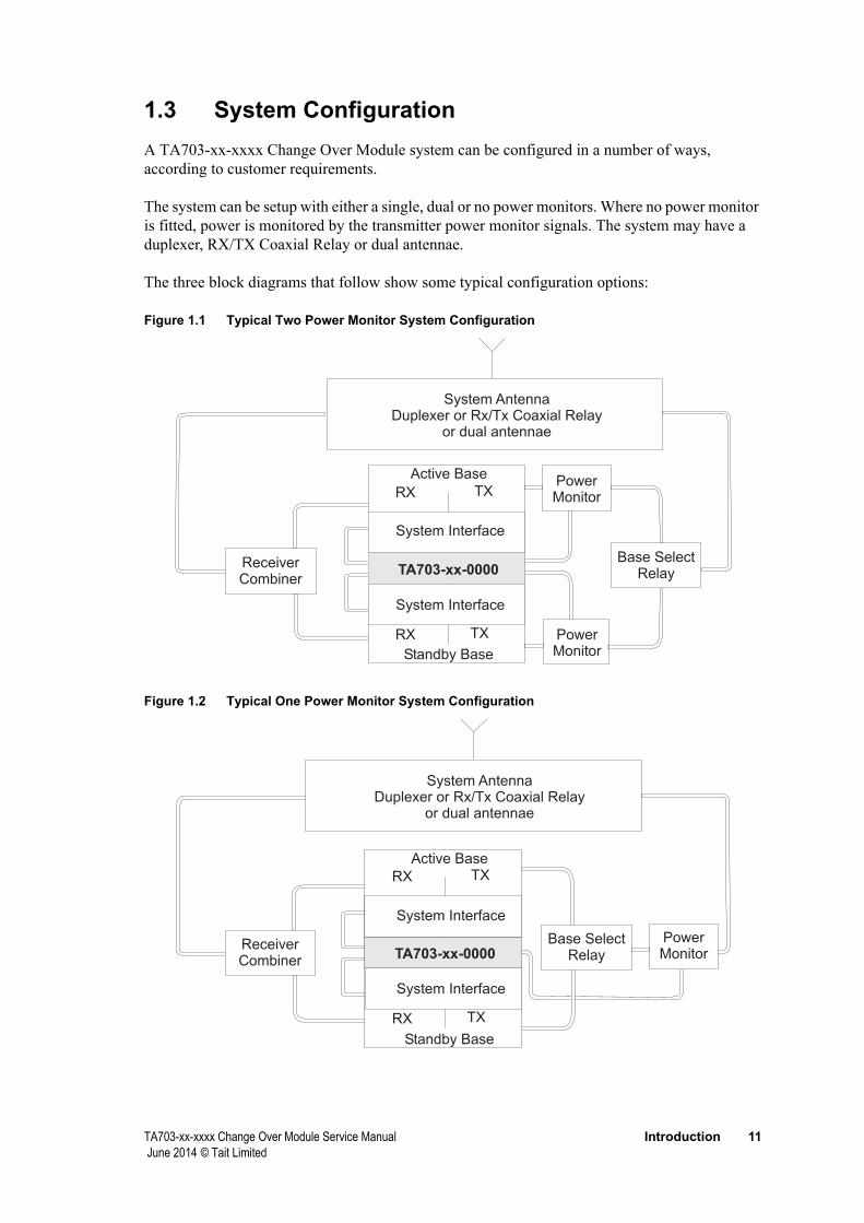
1.3 System ConfigurationA TA703-xx-xxxx Change Over Module system can be configured in a number of ways, according to customer requirements.
The system can be setup with either a single, dual or no power monitors. Where no power monitor is fitted, power is monitored by the transmitter power monitor signals. The system may have a duplexer, RX/TX Coaxial Relay or dual antennae.
The three block diagrams that follow show some typical configuration options:
Figure 1.1 Typical Two Power Monitor System Configuration
Figure 1.2 Typical One Power Monitor System Configuration
SystemDuplexer or Rx/Tx Coaxial Relay
or dual antennae
Antenna
PowerMonitor
PowerMonitor
ReceiverCombiner
Base SelectRelayTA703-xx-0000
RX TX
RX TX
Active Base
Standby Base
System Interface
System Interface
SystemDuplexer or Rx/Tx Coaxial Relay
or dual antennae
Antenna
PowerMonitor
ReceiverCombiner
Base SelectRelayTA703-xx-0000
RX TX
RX TX
Active Base
Standby Base
System Interface
System Interface
12 Introduction TA703-xx-xxxx Change Over Module Service Manual June 2014 © Tait Limited
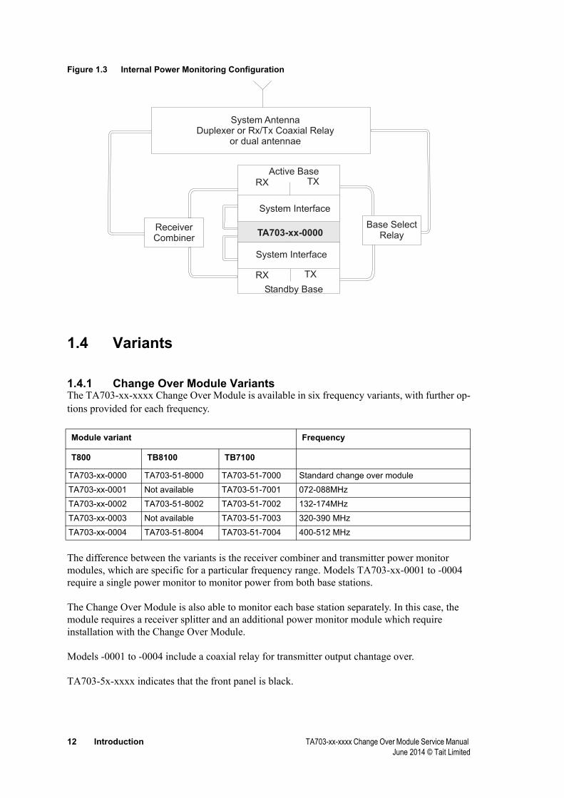
Figure 1.3 Internal Power Monitoring Configuration
1.4 Variants
1.4.1 Change Over Module VariantsThe TA703-xx-xxxx Change Over Module is available in six frequency variants, with further op-tions provided for each frequency.
The difference between the variants is the receiver combiner and transmitter power monitor modules, which are specific for a particular frequency range. Models TA703-xx-0001 to -0004 require a single power monitor to monitor power from both base stations.
The Change Over Module is also able to monitor each base station separately. In this case, the module requires a receiver splitter and an additional power monitor module which require installation with the Change Over Module.
Models -0001 to -0004 include a coaxial relay for transmitter output chantage over.
TA703-5x-xxxx indicates that the front panel is black.
Module variant Frequency
T800 TB8100 TB7100
TA703-xx-0000 TA703-51-8000 TA703-51-7000 Standard change over module
TA703-xx-0001 Not available TA703-51-7001 072-088MHz
TA703-xx-0002 TA703-51-8002 TA703-51-7002 132-174MHz
TA703-xx-0003 Not available TA703-51-7003 320-390 MHz
TA703-xx-0004 TA703-51-8004 TA703-51-7004 400-512 MHz
SystemDuplexer or Rx/Tx Coaxial Relay
or dual antennae
Antenna
ReceiverCombiner
Base SelectRelayTA703-xx-0000
RX TX
RX TX
Active Base
Standby Base
System Interface
System Interface

TA703-xx-xxxx Change Over Module Service Manual Introduction 13 June 2014 © Tait Limited
1.4.2 System Variants
The Change-Over Module is part of a TA703-xx-xxxx system. Each system contains:■ TA703-xx-xxxx Change-Over Unit with a coaxial Relay and a Receiver Splitter in the ordered
frequency band■ installation kit (see section2.2, Installation for details to interface with the specified backplane
or System Interface)■ power monitor kit/s (see section2.2, Installation for details) according to the required power
monitoring options.
The diagram below shows how the system variant numbering system operates:
TA703-y1-0xxxFrequency Band01234
= no splitter or relay= 72-88MHZ= 132-174MHz= 320-390MHz= 400-512MHz
Power Monitors012
= none= one= two
Front Panel
0
5
= beige
= black
System Interface012378
= not specified= T800-50-0000= T800-50-0001= T800-52-0000= TB7100= TB8100
For example, TA703-51-0824 system monitors T8100 base stations which:■ require two separate power monitors■ operate in the 400-512MHz band.

14 Introduction TA703-xx-xxxx Change Over Module Service Manual June 2014 © Tait Limited
1.5 Specifications
Supply Voltage 10.8 - 16V DC
Current Consumption 100mA
Change Over by transparent latching relays
2 wire Rx Audio
2 wire Tx Audio
Rx-Gate + RSSI
Tx-Key
Coaxial Relay for Transmitter Output
Switch time 3ms after fault detection
Notice Receiver signals are derived from a single antenna and split to the respective receiv-ers by a low insertion loss power splitter.
Change Over Criteria Supply
Forward Power
Reverse Power
RSSI
Rx-Gate
External Alarms All Alarm - Base A
Supply - Base A
Forward Power - Base A
Reverse Power - Base A
RSSI - Base A
Rx-Gate - Base A
All Alarm - Base B
Supply - Base B
Forward Power - Base B
Reverse Power - Base B
RSSI - Base B
Rx-Gate - Base B
Low Battery Alarm combined with All Alarm A and B
Alarm Polling Mode A 20mSec
Mode B 10mSec
Mode C 20mSec
Mode D 20mSec
Additional Features Output for Rx/Tx Relay for operation in simplex mode
Optional DC-DC converter to power third-party equipment
TA703-xx-xxxx Change Over Module Service Manual Introduction 15 June 2014 © Tait Limited
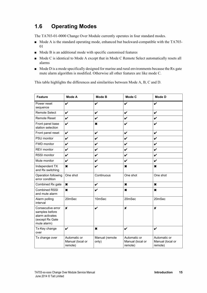
1.6 Operating ModesThe TA703-01-0000 Change Over Module currently operates in four standard modes.■ Mode A is the standard operating mode, enhanced but backward-compatible with the TA703-
01■ Mode B is an additional mode with specific customised features■ Mode C is identical to Mode A except that in Mode C Remote Select automatically resets all
alarms■ Mode D is a mode specifically designed for marine and rural environments because the Rx gate
mute alarm algorithm is modified. Otherwise all other features are like mode C.
This table highlights the differences and similarities between Mode A, B, C and D.
Feature Mode A Mode B Mode C Mode D
Power reset sequence
✔ ✔ ✔ ✔
Remote Select ✔ ✔ ✔ ✔
Remote Reset ✔ ✔ ✔ ✔
Front panel base station selection
✔ ✖ ✔ ✔
Front panel reset ✔ ✔ ✔ ✔
PSU monitor ✔ ✔ ✔ ✔
FWD monitor ✔ ✔ ✔ ✔
REV monitor ✔ ✔ ✔ ✔
RSSI monitor ✔ ✔ ✔ ✔
Mute monitor ✔ ✔ ✔ ✔
Independent TX and Rx switching
✖ ✔ ✖ ✖
Operation following error condition
One shot Continuous One shot One shot
Combined Rx gate ✖ ✔ ✖ ✖
Combined RSSI and mute alarm
✖ ✔ ✖ ✖
Alarm polling interval
20mSec 10mSec 20mSec 20mSec
Consecutive error samples before alarm activates (except Rx Gate mute alarm)
✘ ✔ ✘ ✘
Tx-Key change over
✔ ✖ ✔ ✔
Tx change over Automatic or Manual (local or remote)
Manual (remote only)
Automatic or Manual (local or remote)
Automatic or Manual (local or remote)

16 Introduction TA703-xx-xxxx Change Over Module Service Manual June 2014 © Tait Limited
Rx change over Automatic or Manual (local or remote)
Automatic Automatic or Manual (local or remote)
Automatic or Manual (local or remote)
Default Base Selected Base A (Rx) Selected (Tx)
Selected Selected
Remote Select automatically resets all alarms
✖ Tx only switches without reset
✔ ✔
No of Rx gate opening before change over
3x in 1 sec 3x in 1 sec 5x in 3 sec
Gates combined ✔
Remote forced change-over
Remote change over (Tx select) level change +Pulse low on rem Alm Clear
Remote change over (Tx select) level change only
As A
Combined RSSI and Rx Gate alarm
✔
Feature Mode A Mode B Mode C Mode D

TA703-xx-xxxx Change Over Module Service Manual Introduction 17 June 2014 © Tait Limited
1.7 Hardware Description
1.7.1 General
The TA703-xx-xxxx Change Over Module consists of a 1U 19” rack mount unit with switches and LED indicators on the front panel, and connectors on the rear. Inside the unit a single Control PCB, flush-mounted against the front panel, interfaces to the base stations and customer’s equipment via D-range connectors on the back panel. Power monitor cables connect via RCA sockets on the back panel. A 4-way terminal block connects to two coaxial relays, one for base selection and one for RX/TX change over.
DCInput 13.8V
Coaxial Relay Driver Outputs
FWD
(B)FW
D(A)
ModemInterface
Alarms Out
4 Wire E&M
Radio Interface (B)
Radio Interface (A)
Front Panel
Rear PanelEarthing Tag (optional)
TA703 PCB
Power
Coaxial RelayTerminals
RCASockets
Customer EquipmentConnectors
Battery Indicator
Base B Indicators
Base A Indicators
Reset
Base select
T800 Connectors

18 Introduction TA703-xx-xxxx Change Over Module Service Manual June 2014 © Tait Limited
1.7.2 Front Panel
The Change Over Module front panel has a series of LED indicators, switches, and preset resistors.
T800 Change Over Module
Reset Base
A B
Active Stdby TX RX FWD REV PSU RSSI MUTE Active Stdby TX RX FWD REV PSU RSSI MUTE BATT LOW
Base A Base B
■ 1 x momentary push button switch to clear and reset after an error condition■ 1 x double throw, double pole toggle switch for local, manual base station selection■ 2 x yellow LEDs indicating active or standby status for Base A■ 2 x green LEDs indicating TX and RX activity for Base A■ 5 x red LEDs indicating error conditions on Base A■ 3 x preset resistors for adjusting fault condition trigger levels for Base A faults■ 2 x yellow LEDs indicating active or standby status for Base B■ 2 x green LEDs indicating TX and RX activity for Base B■ 5 x red LEDs indicating error conditions on Base B■ 3 x preset resistors for adjusting fault condition trigger levels for Base B faults■ 1 x red LED indicating battery power status■ 1 x preset resistor for adjusting battery fault trigger level
Notice A more detailed description of these components is included in section 4, Operation.
1.7.3 Rear Panel
The Change Over Module rear panel has a series connectors as shown below.
Modem InterfaceRelay Driver Outputs Alarms Out 4 Wire E&M Radio Interface (B) Radio Interface (A)
REV (B)
FWD (B) FWD (A)
REV (A)+13.8V
RX/TX+13.8V
SelectBase
■ Connection to the Change Over Module is as follows:■ 4 pin XLR plug Power Input (+13.8v, 1.2A max)■ Tag-strip for Co-axial relay control output.■ 4 x RCA sockets for Forward and Reverse power on Base A and Base B■ A separate 25 pin D-range plug provides customer-specific interface (modem, not normally
fitted).■ 1 x 15 pin D-range plug to provide the switched receiver and transmitter signals to the
customers remote control site ■ 1 x 15 pin D-range plug to provide the alarm signals to the remote control site ■ 2 x 15 pin D-range connectors plug for connection to Base A and Base B. ■ Earthing tag (optional)
Notice Pin out information for these connectors is included in section 5, Circuit Description.
TA703-xx-xxxx Change Over Module Service Manual Introduction 19 June 2014 © Tait Limited
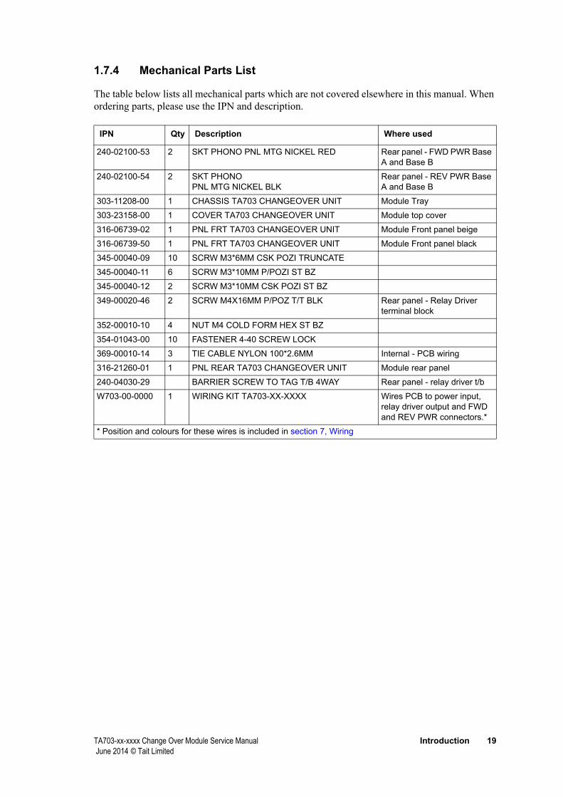
1.7.4 Mechanical Parts List
The table below lists all mechanical parts which are not covered elsewhere in this manual. When ordering parts, please use the IPN and description.
240-02100-53 2 SKT PHONO PNL MTG NICKEL RED Rear panel - FWD PWR Base A and Base B
240-02100-54 2 SKT PHONO PNL MTG NICKEL BLK
Rear panel - REV PWR Base A and Base B
303-11208-00 1 CHASSIS TA703 CHANGEOVER UNIT Module Tray
303-23158-00 1 COVER TA703 CHANGEOVER UNIT Module top cover
316-06739-02 1 PNL FRT TA703 CHANGEOVER UNIT Module Front panel beige
316-06739-50 1 PNL FRT TA703 CHANGEOVER UNIT Module Front panel black
345-00040-09 10 SCRW M3*6MM CSK POZI TRUNCATE
345-00040-11 6 SCRW M3*10MM P/POZI ST BZ
345-00040-12 2 SCRW M3*10MM CSK POZI ST BZ
349-00020-46 2 SCRW M4X16MM P/POZ T/T BLK Rear panel - Relay Driver terminal block
352-00010-10 4 NUT M4 COLD FORM HEX ST BZ
354-01043-00 10 FASTENER 4-40 SCREW LOCK
369-00010-14 3 TIE CABLE NYLON 100*2.6MM Internal - PCB wiring
316-21260-01 1 PNL REAR TA703 CHANGEOVER UNIT Module rear panel
240-04030-29 BARRIER SCREW TO TAG T/B 4WAY Rear panel - relay driver t/b
W703-00-0000 1 WIRING KIT TA703-XX-XXXX Wires PCB to power input, relay driver output and FWD and REV PWR connectors.*
* Position and colours for these wires is included in section 7, Wiring
IPN Qty Description Where used

20 Introduction TA703-xx-xxxx Change Over Module Service Manual June 2014 © Tait Limited
TA703-xx-xxxx Change Over Module Service Manual Setup and Installation 21 June 2014 © Tait Limited
2 Setup and Installation
This part contains information for installing the TA703-xx-xxxx Change Over Module with two base stations. It contains:■ Internal Setup■ Installation■ Rack Installation■ Connection to Typical Base■ Power Monitor Installation
2.1 Internal SetupThe Change Over Module requires the following selections to be made for correct setup. Refer to section 2.1.6, Internal Link Setting and section 2.1.7, Dip Switch and Test Point Location for further details.
2.1.1 Mode Select
Refer to section 1.6, Operating Modes.■ Mode A SW201-1 off, SW201-2 on■ Mode B SW201-1 on, SW201-2 off■ Mode C SW201-1 off, SW201-2 off■ Mode D SW201-1 on, SW201-2 on
2.1.2 Repeater Mode Versus Base Station Mode■ Close SW100-1 and SW100-2 to link Rx Audio to Tx Audio■ Close SW100-6 to link Rx Gate to Tx-Key
2.1.3 Forward and Reverse Power Measurements
There are two options for alarm detection in the TA703: ■ You can opt to use analog forward and reverse metering signals taken either from the PA or
from one or two external power monitors. In this case you need to open SW201-6 and SW201-7. This shuts out the digital alarm outputs from the PA. Always use external monitors for TB8100 and TB7100.
■ For T800 PAs, you can select the digital alarm signals generated in the PA. These signals are active high in the T800. The T800 forward power alarm goes high impedance when the forward power does not reach its required level.

22 Setup and Installation TA703-xx-xxxx Change Over Module Service Manual June 2014 © Tait Limited
Set SW201-6 and SW201-7 to close. In this case you may also need to adjust the alarm trigger level in the PA to the desired level. You must set the front panel trimmers on the Change Over Module for forward and reverse power alarm to 0.
■ For TB8100 PAs a task manager script needs to be written:■ If forward power low then activate Dig Output 1, ■ If reverse power high then activate Dig Output 2.
■ The TB7100 does not provide digital outputs reflecting the forward and reverse power status. External power monitor(s) have to be used instead.
2.1.4 Single External Power Monitor
When you have only one single external power monitor, close SW201-5 and SW201-8.
This links the inputs of Base A and Base B for both the forward and reverse power measurements
2.1.5 Alarm Outputs
There is one more selection to be considered with regard to the alarm outputs
SW400 and SW401 allows for a small variety in output settings. SW400 deals with the outputs of Base A, while SW401 does the same for Base B
When a switch on SW400 or SW401 is closed a 1k pull up resistor is connected to 13.8V. Refer to table SW400 in. Defaults is: no pull up.
2.1.6 Internal Link Setting
All internal link settings are by dip switch. Four dip switches SW100, SW201, SW400 and SW401 provide separate, adjustable internal links on the TA703-01-0000 PCB to allow the Change Over Module to perform as described in the table below. See the diagram on page on page 25 for dip switch locations.
Notice Some switches are unused.

TA703-xx-xxxx Change Over Module Service Manual Setup and Installation 23 June 2014 © Tait Limited
SW100 (Shaded fields indicate default settings)
1-16 Repeater mode Base Station mode Repeater Audio +
2-15 Repeater mode Base Station mode Repeater Audio -
3-14 disable remote batt sense enable remote batt sense remote battery sense option
4-13 not connected
5-12 not connected
6-11 Repeater mode Base Station mode RxTx key
7-10 enable disable for testing Tx-key B Enable
8-9 enable disable for testing Tx-key A Enable
SW 201 (Shaded fields indicate default settings)
1-16 Modes B and D Modes A and C Operating mode
2-15 Modes A and D Modes B and C Operating mode
3-14 not used
4-13 not used
5-12 Rev Pwr inputs linked Rev Pwr inputs separate Reverse power input
6-11 enable Fwd Alm B I/P disable Fwd Alm B I/P Disable for Fwd and Rev power metering inputs
7-10 enable Fwd Alm A I/P disable Fwd Alm A I/P Disable for Fwd and Rev power metering inputs
8-9 Fwd Pwr inputs linked Fwd Pwr inputs separate Forward power input
SW 400 (Shaded fields indicate default settings)
1-16 Fwd Pwr A 1k to V+ pull up Fwd Pwr A open collector Fwd Pwr A pull up select
2-15 Rev Pwr A 1k to V+ pull up Rev Pwr A open collector Rev Pwr A pull up select
3-14 Mute A 1k to V+ pull up Mute A open collector Mute A pull up select
4-13 RSSI A 1k to V+ pull up RSSI A open collector RSSI A pull up select
5-12 PSU A 1k to V+ pull up PSU A open collector PSU A pull up select
6-11 not used
7-10 All Alm-A common Gnd All Alm A common float All Alm-A common select
8-9 All Alm A N/O 1k to V+ All Alm A N/O float All Alm-A pull up select
Switch on off comment
Switch on off comments
Switch on off comments

24 Setup and Installation TA703-xx-xxxx Change Over Module Service Manual June 2014 © Tait Limited
SW 401 (Shaded fields indicate default settings)
1-16 Rev Pwr B 1k to V+ Rev Pwr B open collector Rev Pwr B pull up select
2-15 Fwd Pwr B 1k to V+ Fwd Pwr B open collector Fwd Pwr B pull up select
3-14 Mute B 1k to V+ Mute B open collector Mute B pull up select
4-13 RSSI B 1k to V+ RSSI B open collector RSSI B pull up select
5-12 PSU B 1k to V+ PSU B open collector PSU B pull up select
6-11 not used
7-10 All Alm-B common to Gnd All Alm-B common float All Alm-B common select
8-9 All Alm-B N/O 1k to V+ All Alm-B N/O float All Alm-B pull up select
Switch on off comments

TA703-xx-xxxx Change Over Module Service Manual Setup and Installation 25 June 2014 © Tait Limited
2.1.7 Dip Switch and Test Point Location
LM
JK
HF
GE
DC
BA
NP
QR
1 2 3 4 5 6 7
*C160
*C161 *C
162
*C163
*C164
*C165
*IC112
*R238
C100
C101
C102
C105
C105A
C105B
C106
C106A
C106B
C110
C114
C118
C120
C121
C122
C123
C126
C127
C128
C131
C200
C201
C203
C220 C221
C224
C228
C229
C232
C233
C237C238
C243
C244
C245
C246
C249
C253
C254
C257
C258
C320
C321
C322
C327
C328
C331
C332
C333
C335
C338
C339
C400
C401
C420
C421C422C423C424C425
C429
C430
C431
C432
C433
C436
C437 C438C439C440C441
C445
C446
C447
C448
C449
D100
D101
D102
D103
D107
D108
D109
D110
D112
D115
D202
D205
D210
D211
D300
D301
D302
D305
D306
D307D308
D311
D312
D313D314
D400
D401
D402
D403
D404
D405
D408
D409
D410
D411
D414
D415
D416
D417
D418
D419
FIDA
FIDB
IC100
IC101
IC102
IC105
IC106
IC109
IC110
IC111
IC200
IC201
IC202
IC203
IC204
IC207
IC300
IC301
IC400
IC401
P100
P101
P102
P103
P105
P106
P107
P108
P200
P202
P203
P204
P205
P208
P209
P210
P211
P213
P220
P221
PL1
PL2
PL3
PL4
Q100Q101
Q102
Q103
Q106
Q107
Q200
Q201
Q202
Q300
Q301
Q302
Q303
Q307
Q308
Q309
Q310
Q400
Q401
Q404
Q405
Q406
Q407
Q408
Q409
Q410
Q411
Q412
Q413
Q414
Q418
Q419
Q422
Q423
Q424
Q425
Q426
Q427
Q428
Q429
Q430
Q431
Q432
R105
R106
R120
R121
R127
R128
R135
R136
R137R138
R139 R140
R141
R142R143
R146 R147
R148
R149
R152
R153
R157
R158
R159
R213
R220 R221
R224
R228
R229
R230
R233
R234
R235
R236
R237
R239
R243
R244
R245
R246
R247
R248 R249
R250
R251
R252
R255
R256
R257
R258R259
R260 R261
R264
R266
R269
R270
R271
R272
R273
R274
R275
R276
R277 R278R279
R280
R281
R283
R284
R285
R286
R287
R288
R289
R290
R320
R321
R322
R323
R324
R325
R328
R329
R330
R331
R332
R333
R334
R335
R336
R337
R341
R342
R343
R344
R347
R348
R349
R350
R354
R355
R356
R357
R358
R359
R363
R364
R365
R366
R367
R368
R371
R372
R373
R374
R378
R379
R380
R381
R384
R385
R386
R387
R420
R421
R422
R423
R424
R425
R428 R429
R430
R431
R432
R433
R437 R438
R439
R450
R451 R452
R453
R454
R458 R459
R460
R461
R462 R463
R464
R465
R469
R470
R471
R472
R473
R474
R478 R479
R480
R481
R482
R483
R484 R485
R486
R487
R490 R491
R492
R493
R494 R495
R496
R497
R498 R499
R500
R501
RL100
RL101
RL102
RL103
RL400
RL401
RV100
RV101
RV102
RV203
RV204
RV205
RV206
RV
300
RV
301
SK
1
SW
100
SW
200
SW
201
SW
202
SW
400S
W401
THO
LE
TP300
TP301
TP302
TP305
TP310
TP311
TSLO
T
X200
RV
300
RV
301
SW400
TP300
TP305
SW201OFF
1 2 3 4 5 6 7 8
SW100OFF
1 2 3 4 5 6 7 8
OFF
1 2 3 4 5 6 7 8
OFF
1 2 3 4 5 6 7 8
Switch Block SW201
Switch Block SW100
Switch Block SW400
Switch Block SW401
TP305
TP300
RV300
RV301
SW401
TP311 TP311
TP310TP310
Re
se
tR
es
et
Ba
se
AB
Ac
tive
Ac
tive
Ac
tive
Ac
tive
Std
by
Std
by
TX
TX
RX
RX
RX
RX
Ba
se
BB
as
eB
Ba
se
AB
as
eA F
WD
FW
DF
WD
FW
DB
AT
TL
OW
BA
TT
LO
WR
EV
RE
VP
SU
PS
UR
SS
IR
SS
IR
SS
IR
SS
IM
UT
EM
UT
EM
UT
EM
UT
E
26 Setup and Installation TA703-xx-xxxx Change Over Module Service Manual June 2014 © Tait Limited
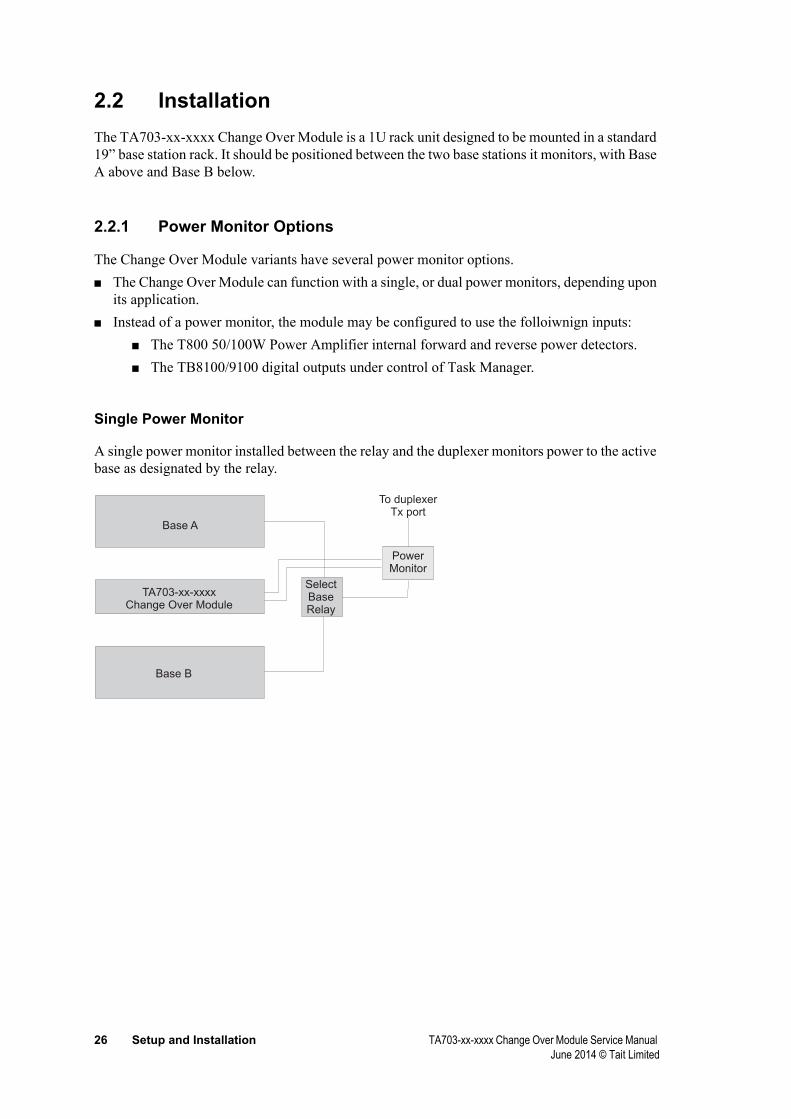
2.2 InstallationThe TA703-xx-xxxx Change Over Module is a 1U rack unit designed to be mounted in a standard 19” base station rack. It should be positioned between the two base stations it monitors, with Base A above and Base B below.
2.2.1 Power Monitor Options
The Change Over Module variants have several power monitor options.■ The Change Over Module can function with a single, or dual power monitors, depending upon
its application.■ Instead of a power monitor, the module may be configured to use the folloiwnign inputs:
■ The T800 50/100W Power Amplifier internal forward and reverse power detectors.■ The TB8100/9100 digital outputs under control of Task Manager.
Single Power Monitor
A single power monitor installed between the relay and the duplexer monitors power to the active base as designated by the relay.
Base A
Base B
TA703-xx-xxxxChange Over Module
SelectBaseRelay
PowerMonitor
To duplexerTx port
TA703-xx-xxxx Change Over Module Service Manual Setup and Installation 27 June 2014 © Tait Limited
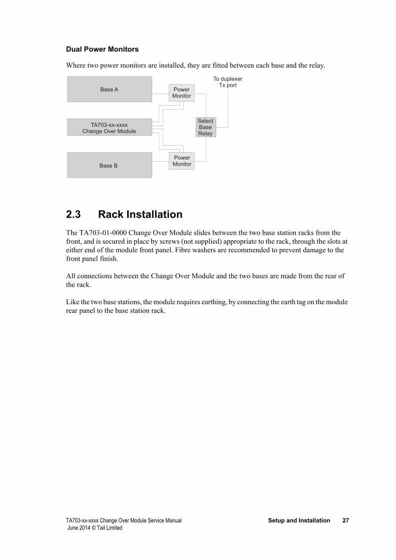
Dual Power Monitors
Where two power monitors are installed, they are fitted between each base and the relay.
Base A
Base B
TA703-xx-xxxxChange Over Module
SelectBaseRelay
To duplexerTx port
PowerMonitor
PowerMonitor
2.3 Rack InstallationThe TA703-01-0000 Change Over Module slides between the two base station racks from the front, and is secured in place by screws (not supplied) appropriate to the rack, through the slots at either end of the module front panel. Fibre washers are recommended to prevent damage to the front panel finish.
All connections between the Change Over Module and the two bases are made from the rear of the rack.
Like the two base stations, the module requires earthing, by connecting the earth tag on the module rear panel to the base station rack.

28 Setup and Installation TA703-xx-xxxx Change Over Module Service Manual June 2014 © Tait Limited
2.4 Connection to Typical Base
2.4.1 Installation Kits
Each Kit contains eight cables. Note that the IPN of the base station to Change Over Module cable is different for each kit variant.
2 x 15 way to 25 way D Range cableIPN 219-02702-01 (kit TA703-11-0010)IPN 219-02703-01 (kit TA703-11-0011)IPN 219-02700-01 (kit TA703-11-0012)IPN 219-03115-00 (kit TA703-11-7010)IPN 219-03460-00 (kit TA703-11-8010)
6 x N-type male to N-type male cableIPN 219-02701-00
TA703-xx-xxxx Change Over Module Service Manual Setup and Installation 29 June 2014 © Tait Limited
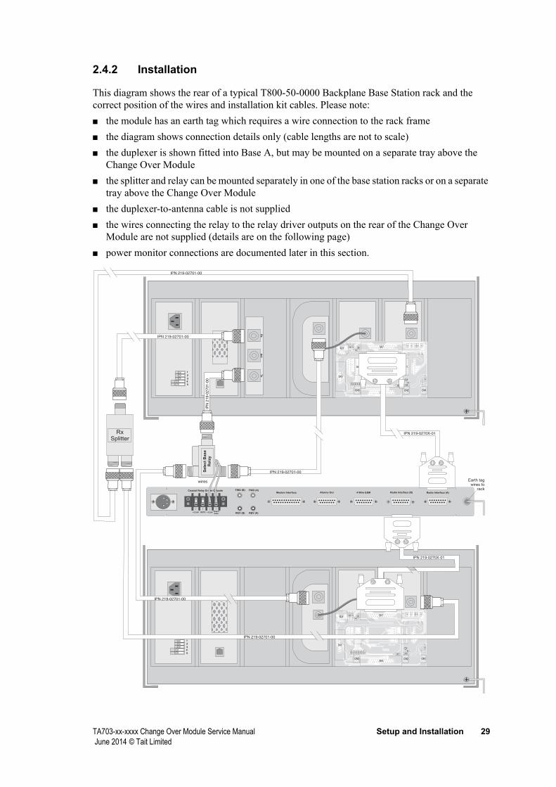
2.4.2 Installation
This diagram shows the rear of a typical T800-50-0000 Backplane Base Station rack and the correct position of the wires and installation kit cables. Please note:■ the module has an earth tag which requires a wire connection to the rack frame■ the diagram shows connection details only (cable lengths are not to scale)■ the duplexer is shown fitted into Base A, but may be mounted on a separate tray above the
Change Over Module■ the splitter and relay can be mounted separately in one of the base station racks or on a separate
tray above the Change Over Module■ the duplexer-to-antenna cable is not supplied■ the wires connecting the relay to the relay driver outputs on the rear of the Change Over
Module are not supplied (details are on the following page)■ power monitor connections are documented later in this section.
REV (B)
FWD (B) FWD (A)
REV (A)
Modem Interface Alarms Out 4 Wire E&M Radio Interface (B) Radio Interface (A)
RXTX+13.8V +13.8VSelectbase
Coaxial Relay Driver Outputs
1
1
2
2
3
3
4
4
5
5
IPN 219-0270X-01
IPN 219-02701-00
IPN 219-02701-00
IPN
21
9-0
27
01
-00
BASE (A)BASE (A)
Rx
An
tT
x
IPN 219-02701-00
IPN 219-02701-00
IPN 219-0270X-01
IPN 219-02701-00
RxSplitter
Se
lec
tB
as
eR
ela
y
wires Earth tagwires to
rack
30 Setup and Installation TA703-xx-xxxx Change Over Module Service Manual June 2014 © Tait Limited
The table below describes placement of the connectors.
219-02701-00 N-Type to N-Type Cable RX(A) Receiver (A) rear socket
RX(B) Receiver (B) rear socket
TX (ANT) Duplexer Tx socket
Rx (ANT) Duplexer Rx socket
Tx (A) PA (A) rear socket
Tx (B) PA (B) rear socket
219-0270X-01* 15-way to 25-way D Range Cable Base (A) Backplane PCB SK7
Base (B) Backplane PCB SK7
* This IPN refers to 219-02700-01, 219-02702-01 or 219-02703-01.
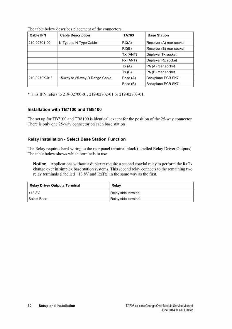
Installation with TB7100 and TB8100
The set up for TB7100 and TB8100 is identical, except for the position of the 25-way connector. There is only one 25-way connector on each base station
Relay Installation - Select Base Station Function
The Relay requires hard-wiring to the rear panel terminal block (labelled Relay Driver Outputs). The table below shows which terminals to use.
Notice Applications without a duplexer require a second coaxial relay to perform the RxTx change over in simplex base station systems. This second relay connects to the remaining two relay terminals (labelled +13.8V and RxTx) in the same way as the first.
Cable IPN Cable Description TA703 Base Station
Relay Driver Outputs Terminal Relay
+13.8V Relay side terminal
Select Base Relay side terminal

TA703-xx-xxxx Change Over Module Service Manual Setup and Installation 31 June 2014 © Tait Limited
The following instructions and diagram describe the correct installation procedure.
1. Cut two 7/0.2 PVC wires to required length.
Solder wires toside ring terminals
Fit wires to RelayDriver terminals
according to table
Fit wires from secondrelay (if used) to theseRelay Driver terminals
REV (B)
FWD (B) FWD (A)
REV (A)RXTX+13.8V +13.8VSelectbase
Coaxial Relay Driver Outputs
Se
lec
tB
as
eR
ela
y
wires
2. Strip both ends of each 10mm and tin.
3. Solder one wire to each of the relay side ring terminals.
4. Remove screw from Relay Driver Outputs terminal labelled +13.8V.
5. Fit one wire into terminal and replace screw.
6. Remove screw from Relay Driver Outputs terminal labelled Select Base.
7. Fit remaining wire into terminal and replace screw.
Notice Reverse Voltage Transient Protection diode is built into the TA703-01-0000 cir-cuitry.

32 Setup and Installation TA703-xx-xxxx Change Over Module Service Manual June 2014 © Tait Limited
2.5 Power Monitor InstallationA single, or pair of Power Monitors monitor transmitter forward and reverse power. The unit is placed in series with the Transmitter Antenna Cable, preferably after the duplexer. The kits provide for a choice of installation options: ■ installed directly in series with the antenna port of the duplexer via the barrel adapter provided ■ connected to the duplexer via the coaxial cable provided.
A second Power Monitor kit is required if Base A and Base B are monitored separately.
2.5.1 Power Monitor Kits - all variants
Each kit contains the following items:
2x Twin Phono/Phono CableIPN 219-00025-82
1x Dual Power MonitorIPN 009-00000-01 (30-88MHz)IPN 009-00000-02 (118-512MHz)IPN 009-00000-03 (806-960MHz)
1 x N-type male /N-type male adapterIPN 240-06020-04
1 x N-type male/N-type male cableIPN 219-02701-00
More details of the cables follow in section 7, Wiring.
TA703-xx-xxxx Change Over Module Service Manual Setup and Installation 33 June 2014 © Tait Limited
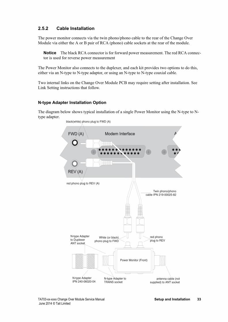
2.5.2 Cable Installation
The power monitor connects via the twin phono/phono cable to the rear of the Change Over Module via either the A or B pair of RCA (phono) cable sockets at the rear of the module.
Notice The black RCA connector is for forward power measurement. The red RCA connec-tor is used for reverse power measurement
The Power Monitor also connects to the duplexer, and each kit provides two options to do this, either via an N-type to N-type adaptor, or using an N-type to N-type coaxial cable.
Two internal links on the Change Over Module PCB may require setting after installation. See Link Setting instructions that follow.
N-type Adapter Installation Option
The diagram below shows typical installation of a single Power Monitor using the N-type to N-type adapter
Modem InterfaceModem Interface AFWD (A)FWD (A)
REV (A)REV (A)
red phono plug to REV (A)
White (or black)phono plug to FWD
black(white) phono plug to FWD (A)
red phonoplug to REV
Power Monitor (Front)
antenna cable (notsupplied) to ANT socket
N-type Adapter toTRANS socket
N-type Adapterto DuplexerANT socket
Twin phono/phonocable IPN 219-00025-82
N-type AdapterIPN 240-06020-04
.
34 Setup and Installation TA703-xx-xxxx Change Over Module Service Manual June 2014 © Tait Limited
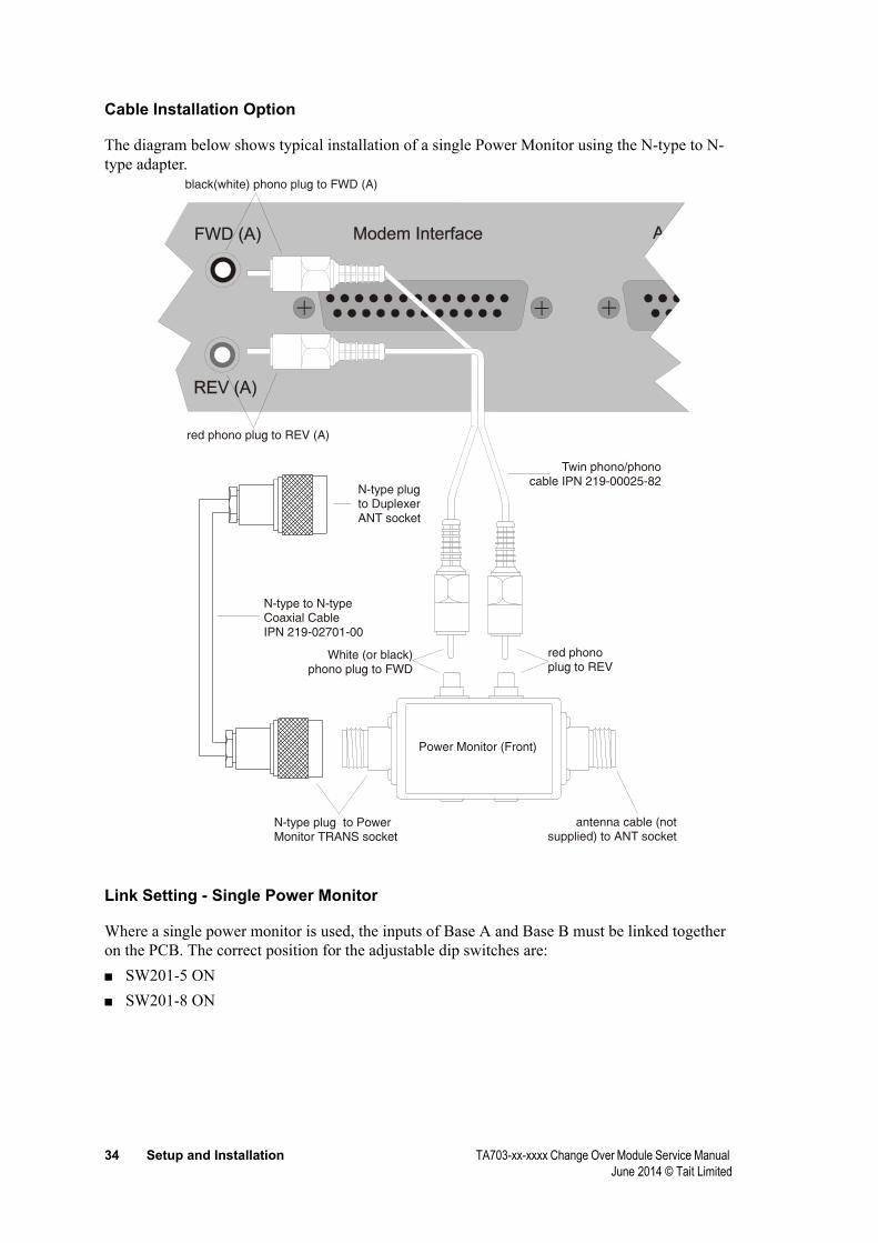
Cable Installation Option
The diagram below shows typical installation of a single Power Monitor using the N-type to N-type adapter.
red phono plug to REV (A)
White (or black) phono plug to FWD
black(white) phono plug to FWD (A)
red phono plug to REV
Power Monitor (Front)
antenna cable (not supplied) to ANT socket
Twin phono/phono cable IPN 219-00025-82
N-type plug to PowerMonitor TRANS socket
N-type plug to Duplexer ANT socket
N-type to N-typeCoaxial CableIPN 219-02701-00
Link Setting - Single Power Monitor
Where a single power monitor is used, the inputs of Base A and Base B must be linked together on the PCB. The correct position for the adjustable dip switches are: ■ SW201-5 ON■ SW201-8 ON
TA703-xx-xxxx Change Over Module Service Manual Setup and Installation 35 June 2014 © Tait Limited
2.5.3 Installation - Two Power Monitors
A second Power Monitor is required if Base A and Base B are monitored separately. Where two power monitors are required, each Power Monitor connects via its twin RCA cable to the A and B pairs of RCA (phono) sockets on the rear of the Change Over Module.
Notice The black RCA connectors are for forward power measurement. The red RCA con-nectors are used for reverse power measurement.
From this point, installation will vary according to the individual base setup. For example, there may be either a single, or two duplexer, and a single, or two antennae. Follow the instructions for a single power monitor, noting that extra adaptation may be required.
Notice Link setting for two power monitors is different from the single power monitor set-ting. See below.
Link Setting - Two Power Monitors
Where two power monitors are used, the inputs of Base A and Base B must not be linked together on the PCB. The correct position for the adjustable dip switches are: ■ SW201-5 OFF■ SW201-8 OFF

36 Setup and Installation TA703-xx-xxxx Change Over Module Service Manual June 2014 © Tait Limited
TA703-xx-xxxx Change Over Module Service Manual Calibration and Testing 37 June 2014 © Tait Limited
3 Calibration and Testing
This part contains information for setting, calibrating and testing the TA703-xx-xxxx Change Over Module after initial installation or servicing. It contains:■ Calibration■ External Adjustments■ Test Procedure
3.1 CalibrationNotice All internal adjustments have been preset during manufacturing. If re-adjustment is required proceed as follows:
3.1.1 RSSI
Receiver RSSI output levels need to be set as per the instructions in the relevant base station service manual. The procedure that follows uses the UHF receiver as an example■ Apply a carrier to produce 2V DC at the RSSI input of the TA703-01-0000. For a correctly
setup UHF TB8100 and T800 receiver, that should occur at a RF input level of -110dBm, the RSSI level can be measured at TP310 for Base A and at TP311 for Base B. Otherwise disconnect the receiver and apply 2V to PL1-14 for Base A and 2V to PL2-14 for Base B. The levels in the TB7100 are lower than in the TB8100 and may require resistor changes on the TAQ703 PCB. If the voltages are too low, gain adjustments have to be made in the Change Over Module. Refer to IC201 in page two of the circuit diagram.
■ Put a DC voltmeter probe on TP300 or pin 1 of IC300 and adjust RV300 to read 2.6V■ Put a probe on TP305 or pin 7 of IC300 and adjust RV301 for a reading of 2.6V.
3.1.2 Verifying RSSI operation
1. Select Base A
2. Ensure that both Bases provide the same 2V RSSI voltage
3. Increase the RSSI voltage of Base B slowly, either by increasing the RF input or by increasing the simulated DC input. Stop when LED D300 on the PCB lights up and the TA703-xx-xxxx changes over.
4. This should take place around the 6dB increase in RF power or after a 0.4V increase in DC input.
5. Return the level to normal and reset system
6. Repeat steps 1 to 4 with Base A and B swapped. In this case LED D301 on the PCB lights up
38 Calibration and Testing TA703-xx-xxxx Change Over Module Service Manual June 2014 © Tait Limited
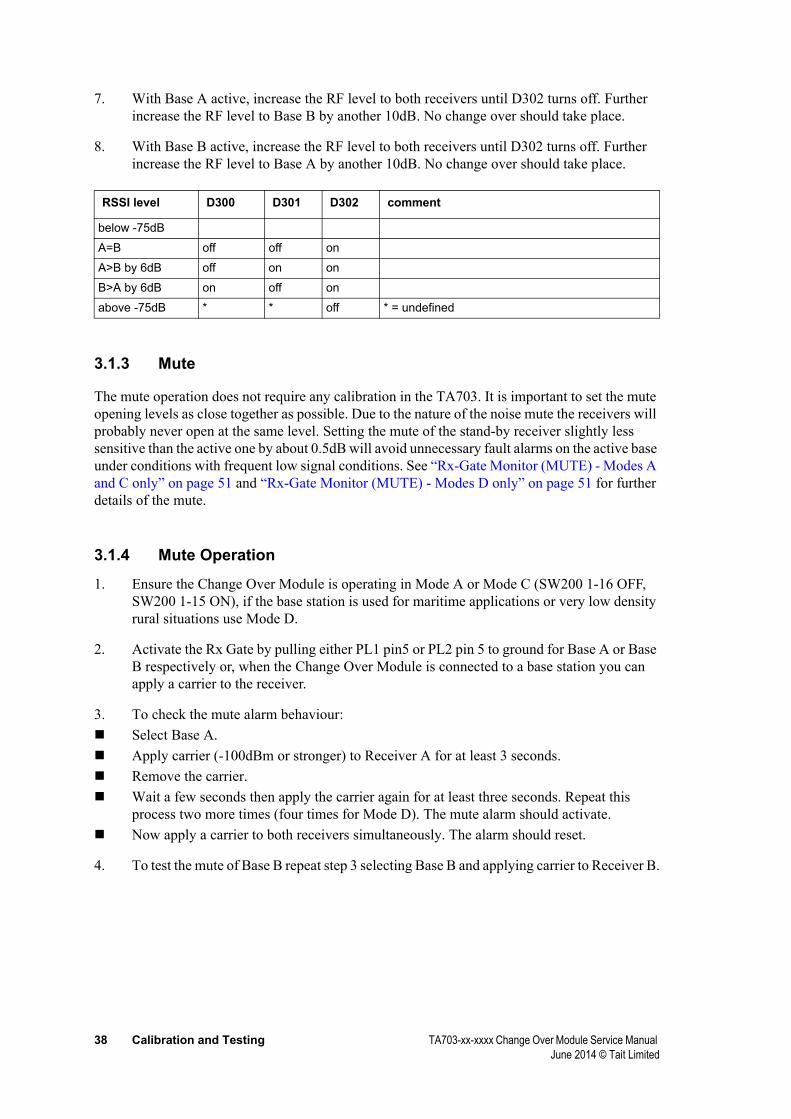
7. With Base A active, increase the RF level to both receivers until D302 turns off. Further increase the RF level to Base B by another 10dB. No change over should take place.
8. With Base B active, increase the RF level to both receivers until D302 turns off. Further increase the RF level to Base A by another 10dB. No change over should take place.
below -75dB
A=B off off on
A>B by 6dB off on on
B>A by 6dB on off on
above -75dB * * off * = undefined
3.1.3 Mute
The mute operation does not require any calibration in the TA703. It is important to set the mute opening levels as close together as possible. Due to the nature of the noise mute the receivers will probably never open at the same level. Setting the mute of the stand-by receiver slightly less sensitive than the active one by about 0.5dB will avoid unnecessary fault alarms on the active base under conditions with frequent low signal conditions. See “Rx-Gate Monitor (MUTE) - Modes A and C only” on page 51 and “Rx-Gate Monitor (MUTE) - Modes D only” on page 51 for further details of the mute.
3.1.4 Mute Operation
1. Ensure the Change Over Module is operating in Mode A or Mode C (SW200 1-16 OFF, SW200 1-15 ON), if the base station is used for maritime applications or very low density rural situations use Mode D.
2. Activate the Rx Gate by pulling either PL1 pin5 or PL2 pin 5 to ground for Base A or Base B respectively or, when the Change Over Module is connected to a base station you can apply a carrier to the receiver.
3. To check the mute alarm behaviour:Select Base A.Apply carrier (-100dBm or stronger) to Receiver A for at least 3 seconds.Remove the carrier.Wait a few seconds then apply the carrier again for at least three seconds. Repeat this process two more times (four times for Mode D). The mute alarm should activate.Now apply a carrier to both receivers simultaneously. The alarm should reset.
4. To test the mute of Base B repeat step 3 selecting Base B and applying carrier to Receiver B.
RSSI level D300 D301 D302 comment
TA703-xx-xxxx Change Over Module Service Manual Calibration and Testing 39 June 2014 © Tait Limited
3.1.5 Reverse Power
1. Activate the relevant transmitter by pulling either PL1 pin7 or PL2 pin 7 to ground for Base A or Base B respectively and check that it produces its nominal power into a 50 Ohm load. Alternately the relevant transmitter may be activated by placing the Change Over Module in repeater mode by closing SW100-6/11 and then apply a carrier to the relevant receiver that will activate the Rx Gate, this will pull down the Tx Key line and activate the transmit-ter.
Notice The carrier switch on the front panel of the base station Exciter/Transmitter does not activate the Tx Key lines in the Change Over Module and cannot be used for power calibration purposes.
2. Reduce the power to 25% of its nominal value. The forward power failure indictor will probably trigger and cause change over when power is reduced to such a low level.
3. Adjust front panel preset on the Change Over Module for the forward power failure trigger to avoid triggering.
4. Remove the termination/50 Ohm load.
5. Adjust front panel preset for the reverse power till the associated LED turns on.
3.1.6 Forward Power
1. Refit the 50 ohm load/termination to the PA.
2. Reduce the power to 50% of its nominal value.
3. Adjust front panel preset on the Change Over Module for the forward power till the associated LED turns on.
4. Reset PA power to nominal power.
3.1.7 Power Supply and Battery
1. Reduce power supply level to 10.8V
2. Adjust the front panel preset until the associated LED turns on
3.1.8 Repeater Audio: Receiver to Transmitter
For repeater setup, adjust receiver line output for -10dBm.

40 Calibration and Testing TA703-xx-xxxx Change Over Module Service Manual June 2014 © Tait Limited
3.2 External AdjustmentsOnce installed, The TA703-01-0000 Change Over Module requires a series of adjustments. These adjustments must be carried out on a live system by introducing defined good conditions and defined error conditions.
3.2.1 Front Panel Adjustments - Base A
The adjustment trim pots are located just above the red LEDs on the left half of the Change Over Module front panel as shown.
T800 Change Over Module
Reset Base
A BActive Stdby TX RX FWD REV PSU RSSI MUTE Active Stdby TX RX FWD REV PSU RSSI MUTE BATT LOW
Base A Base B
Base selector switch
Reset button Base A Indicator LEDs
On front panel, select Base A.
Forward and Reverse Power Alarm Calibration
The calibration should take place in the fully setup system. When calibration starts it is assumed that the forward and reverse metering voltages are of reasonable level. That is, they should be similar to the nominal output levels of the PA operating at its nominal level even if the voltages are derived from external monitors. The Change Over Module has been designed for amplifiers with output levels in the range of 25 to 100 Watts.
If the voltages are too low, gain adjustments have to be made in the TA703. Refer to IC201 in the circuit diagram in section 6, PCB information and section 6.7, Circuit Diagram (227-70301-07) - page 2 of 2.
Reverse Power with 3dB 50 Ohm Attenuation■ Terminate the transmitter aerial output with a 3dB 50 Ohm attenuator. Do not terminate with
50 Ohm load. The termination represents a SWR of 3:1. Approximately 25% of the transmit power is reflected back into the transmitter.
■ Activate the transmitter by pressing the Tx Key button at the front of the exciter/transmitter.■ Adjust the reverse power change over level so that the Change Over Module just changes over.■ Change the termination of the transmitter back to 50 Ohm and press reset on the Change Over
Module.
Reverse Power without 3dB 50 Ohm Attenuation■ If no 3dB attenuator is available, adjust as in section 3.1.6, Forward Power.
Forward Power■ Activate the transmitter by pressing the Tx Key button at the front of the exciter/transmitter.■ Ensure that the power is set to the nominally required output power into a 50 Ohm load at the
aerial output.■ Turn the power level down to 60% of nominal output power.
TA703-xx-xxxx Change Over Module Service Manual Calibration and Testing 41 June 2014 © Tait Limited
■ Adjust the forward power change over level so that the Change Over Module just changes over.■ Re-adjust transmitter power to nominal power.
PSU
The PSU has been preset during manufacturing. If adjustment is required proceed as follows:■ Reduce the Supply voltage of Base A slowly to +10.5V.■ If the Change Over Module has not changed over adjust the PSU preset resistor. Note this
preset operates counter clockwise. To increase the PSU fault trigger level turn the preset counter clockwise.
■ Return supply level to nominal +13.8V
3.2.2 Front Panel Adjustments - Base B
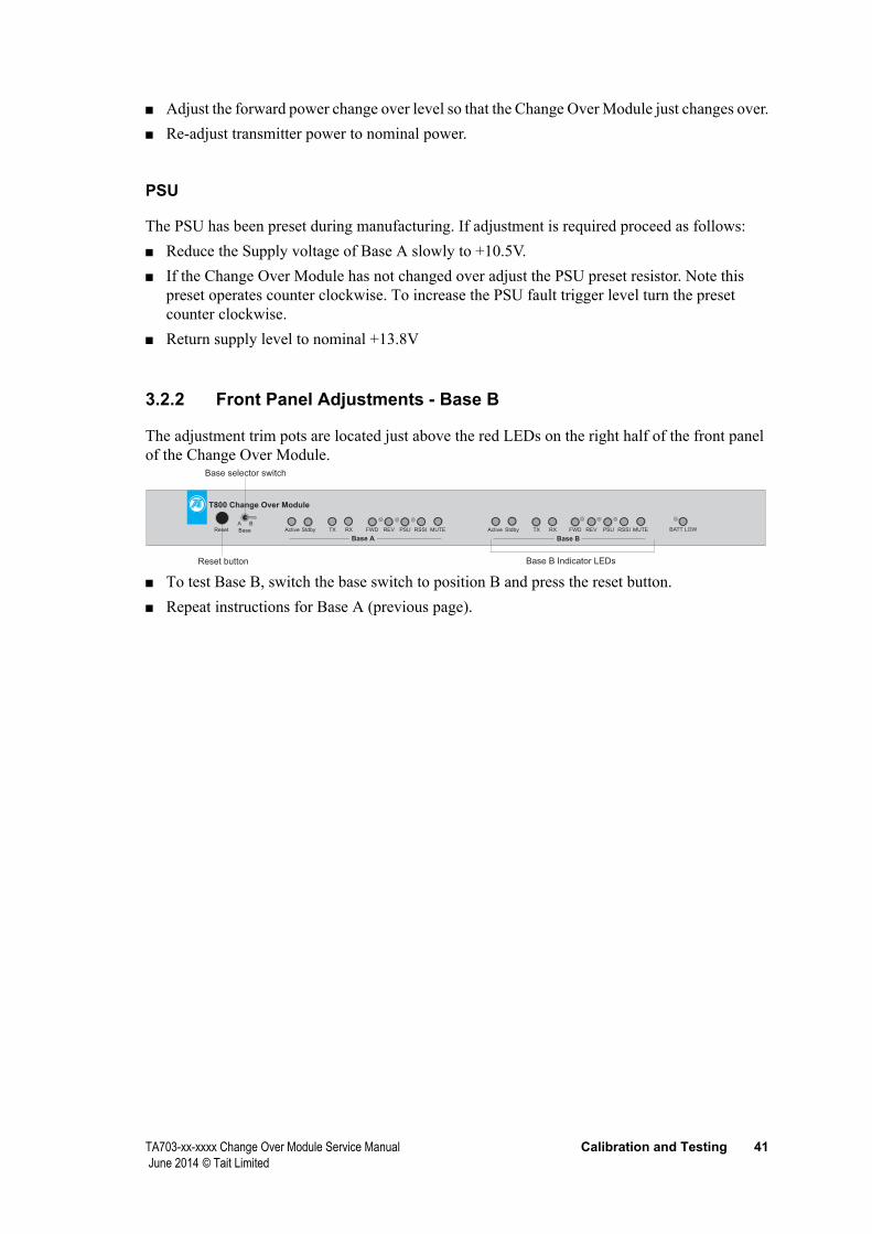
The adjustment trim pots are located just above the red LEDs on the right half of the front panel of the Change Over Module.
T800 Change Over Module
Reset Base
A BActive Stdby TX RX FWD REV PSU RSSI MUTE Active Stdby TX RX FWD REV PSU RSSI MUTE BATT LOW
Base A Base B
Base selector switch
Reset button Base B Indicator LEDs
■ To test Base B, switch the base switch to position B and press the reset button.■ Repeat instructions for Base A (previous page).

42 Calibration and Testing TA703-xx-xxxx Change Over Module Service Manual June 2014 © Tait Limited
3.3 Test ProcedureThe procedure below describes the tests carried out prior to shipping the product. Note that they specify the use of a Change Over Module Test Jig.
Set dip switches as in section 2, Setup and Installation, section 2.1.6, Internal Link SettingSet RSSI pots on test jig to mid levelSet Fwd Pwr pots to maxSet Rev Pwr pots to minSet all switches on test jig to off (white dot)Connect everything together as requiredUse independent power supplies for Base A and Base B. (Red banana socket on test jig is for second supply)
Initial test setup
Test Conditions Result
Audio path and C/O ■ Radio in Base mode
Base A and Base B ■ Turn supply on■ Select TA703 Base A Active■ On TA703 Active A LED ON■ On TA703 Standby B LED ON ■ Jig TX-A and RX-A LEDs ON■ Jig TX and RX Remote LEDs ON■ Measure impedance to gnd at TA703 Base Sel terminal High
■ Activate Jig Rx-B Gate sw■ Change over:■ Jig Active B LED on■ Jig TX-B and RX-B LEDs ON■ Jig TX and RX Remote LEDs ON■ Measure impedance to gnd at TA703 Base Sel terminal Low■ Switch TA703 to Base B and Reset
■ TA703 Active B LED ON■ TA703 Standby A LED ON
TX test Base A ■ Select Base A active■ Set Jig Fwd Pwr pot to max■ Activate Jig Tx RMT Key■ TA703 Green Tx LED Base A ON■ Turn Jig fwd pwr pot down to minimum ■ Change over:■ TA703 Green Tx LED Base B ON■ TA703 Fwd-A Alarm LED ON■ Turn Jig Tx RMT Key off ■ Reset system and set TA703 to Base B
TA703-xx-xxxx Change Over Module Service Manual Calibration and Testing 43 June 2014 © Tait Limited
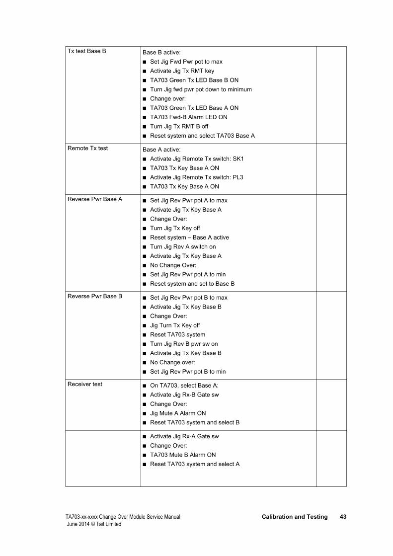
Tx test Base B Base B active:■ Set Jig Fwd Pwr pot to max■ Activate Jig Tx RMT key ■ TA703 Green Tx LED Base B ON■ Turn Jig fwd pwr pot down to minimum■ Change over:■ TA703 Green Tx LED Base A ON■ TA703 Fwd-B Alarm LED ON■ Turn Jig Tx RMT B off ■ Reset system and select TA703 Base A
Remote Tx test Base A active:■ Activate Jig Remote Tx switch: SK1 ■ TA703 Tx Key Base A ON■ Activate Jig Remote Tx switch: PL3 ■ TA703 Tx Key Base A ON
Reverse Pwr Base A ■ Set Jig Rev Pwr pot A to max ■ Activate Jig Tx Key Base A ■ Change Over:■ Turn Jig Tx Key off ■ Reset system – Base A active■ Turn Jig Rev A switch on ■ Activate Jig Tx Key Base A ■ No Change Over:■ Set Jig Rev Pwr pot A to min ■ Reset system and set to Base B
Reverse Pwr Base B ■ Set Jig Rev Pwr pot B to max■ Activate Jig Tx Key Base B■ Change Over:■ Jig Turn Tx Key off■ Reset TA703 system■ Turn Jig Rev B pwr sw on■ Activate Jig Tx Key Base B■ No Change over:■ Set Jig Rev Pwr pot B to min
Receiver test ■ On TA703, select Base A:■ Activate Jig Rx-B Gate sw■ Change Over:■ Jig Mute A Alarm ON■ Reset TA703 system and select B
■ Activate Jig Rx-A Gate sw■ Change Over:■ TA703 Mute B Alarm ON■ Reset TA703 system and select A

44 Calibration and Testing TA703-xx-xxxx Change Over Module Service Manual June 2014 © Tait Limited
Front panel setup
Fwd Pwr Base A setup ■ Setup 1V DC at I/O PAD213
Fwd Pwr Base B setup ■ Setup 1V DC at I/O PAD210
Rev Pwr Base A setup ■ Setup 1V DC at I/O PAD205
Rev Pwr Base B setup ■ Setup 1V DC at I/O PAD202
PSU Base A setup ■ Set Base A supply to 10.5V■ Adjust until PSU-A alarm first appears■ Reset voltage to 13.8V after test
PSU Base B setup ■ Set Base B supply to 10.5V■ Adjust until PSU-B alarm first appears■ Reset voltage to 13.8V after test
Battery test ■ Adjust Battery pot on test jig to min■ All Alarm relays start clicking■ Restore Jig battery voltage■ TA703 Relays stop clicking
Internal controls: RSSI setup
RSSI A setupT855 (-110dBm)T835/T825 -110dBm
■ Set 2.0V DC at RSSI A - R323/C320■ Set 3.8V DC at RSSI A - R323/C320■ Adjust RV300 to read 2.60V +/-.1V at IC300-1 TP300
RSSI B setupT855 (-110dBm)T835/T825 -110dBm
■ Set 2.0V DC at RSSI B - R356/C331■ Set 3.8V DC at RSSI B - R356/C331■ Adjust RV301 to read 2.6V +/-.1V at IC300-7/TP305
RSSI C/O ■ TA703, select Base A■ Set Jig RSSI A to minimum■ Set Jig RSSI B to max■ Activate Jig RX-A plus RX-B Gate■ Changeover:■ TA703 RSSI A Alarm LED ON
■ Select Base B Reset■ Set Jig RSSI B to minimum ■ Set Jig RSSI A to max■ Activate Jig RX-A plus RX-B Gate ■ Changeover: ■ TA703 RSSI B Alarm LED ON
TA703-xx-xxxx Change Over Module Service Manual Operation 45 June 2014 © Tait Limited
4 Operation
This part contains operating information for the TA703-xx-xxxx Change Over Module. It includes the following information:■ Front Panel Functions■ Standard Operation■ Change Over■ Fault Monitoring■ Base Station Selection
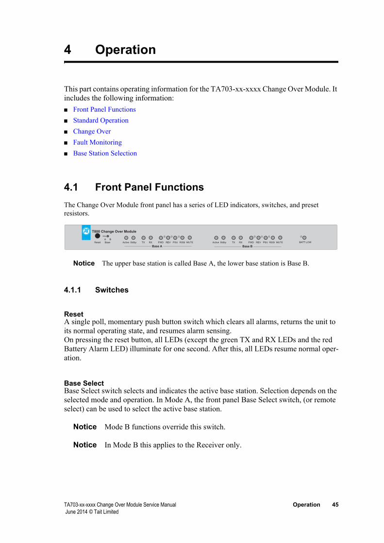
4.1 Front Panel FunctionsThe Change Over Module front panel has a series of LED indicators, switches, and preset resistors.
T800 Change Over Module
Reset Base
A B
Active Stdby TX RX FWD REV PSU RSSI MUTE Active Stdby TX RX FWD REV PSU RSSI MUTE BATT LOW
Base A Base B
Notice The upper base station is called Base A, the lower base station is Base B.
4.1.1 Switches
ResetA single poll, momentary push button switch which clears all alarms, returns the unit to its normal operating state, and resumes alarm sensing.On pressing the reset button, all LEDs (except the green TX and RX LEDs and the red Battery Alarm LED) illuminate for one second. After this, all LEDs resume normal oper-ation.
Base SelectBase Select switch selects and indicates the active base station. Selection depends on the selected mode and operation. In Mode A, the front panel Base Select switch, (or remote select) can be used to select the active base station.
Notice Mode B functions override this switch.
Notice In Mode B this applies to the Receiver only.

46 Operation TA703-xx-xxxx Change Over Module Service Manual June 2014 © Tait Limited
4.1.2 LED Indicators
Two identical sets of LED indicators provide the following signals for Base A and Base B.
Active Indicates the active transmitter
Stdby Indicates the standby transmitter
TX Indicates this transmitter has been keyed
RX Indicates the gate condition of this receiver
FWD Indicates a Forward Power error has occurred
REV Indicates a Reverse Power error has occurred
Mute Indicates a Rx mute error has occurred
Indicates an error has occurred
PSU Indicates a PSU error has occurred
A single red LED labelled Batt Low indicates battery power status for the system.
4.1.3 Preset Resistors
FWD, REV, PSU and Batt Low indicators each has front panel access to a preset resistor. While default levels are factory set, these resistors can be adjusted to suit individual system requirements.
4.2 Standard OperationNotice Base A is the normally active and Base B is the standby, unless stated otherwise.
4.2.1 Power Up
On power up, all LEDs (except green Tx and Rx LEDs and red Batt Low LED) light for one second.
After one second, only one Active and one Stdby (Standby) LED remains on, depending upon the Base switch setting. For example, when the Base switch is set to A, Base A will show its Active LED and Base B will show Stdby.
4.2.2 Transmitting
When a Tx-key is received via the 4 wire E&M connector, the green Tx LED for the active base will turn on.
LED Function

TA703-xx-xxxx Change Over Module Service Manual Operation 47 June 2014 © Tait Limited
4.2.3 Receiving
When either receiver receives a carrier, the Rx Gate signal turns on the green Rx LEDs on the Active and Standby bases. This is because the receivers operate in parallel.
Notice In repeater mode, both Rx LEDs are on, but only Tx LED of the active base.
4.2.4 Change Over
At change over, one red LED (FWD, REV, PSU, , MUTE) of Base A lights to indicate the failure, and the unit changes over to Base B. Base B Active LED lights and its Stdby LED turns off. Base A Active and Standby LEDs are off.
4.2.5 Reset
Base B will remain active until Reset input is received, locally or remotely. Once reset, the module’s internal microprocessor returns operation to Base A and recommences its scan protocol for error conditions.
Notice This does not reset Batt Low indicator
4.2.6 Base Selection - Mode A, C and D Only
The Base switch on the front of the module allows a technician to select which base acts as the active one, by pointing the switch toward A or B, then pressing the reset button. The Active and Stdby LEDs swap when the Base switch is toggled.
4.3 Change Over
4.3.1 Manual Change Over - Mode A,C and D
On power up, the active base is determined by the position of the Base Select switch on the front panel of the module. Remote base selection is ignored until the first negative transient on the remote reset input.
Change over is either: ■ via the front panel with the base select switch, followed by a press of the reset button■ via the remote select and the remote reset input. Note that in Mode C and Mode D, remote
select automatically resets all alarms.

48 Operation TA703-xx-xxxx Change Over Module Service Manual June 2014 © Tait Limited
Both inputs have pull up resistors. The Remote Reset is active
Inputs
Remote Select
Remote Reset
Select A Select B
low.
4.3.2 Mode A Test Function
When the carrier button on the standby receiver or transmitter is pressed, the Change Over Module changes over for the duration of the press, provided the active transmitter is not busy. Alarm indicators and outputs are not latched.
When the standby base station Tx-Key is pressed, the module changes over and remains changed over until it is reset by the reset button on the front panel.
Notice If the test function detects a fault on the standby base station, the fault is indicated, but the base is no longer available as a standby until the fault is repaired and the module reset.
4.3.3 Manual Change Over - Mode B
Notice In this mode the front panel Base Select switch has no effect.
On power up the Change Over Module always defaults to Base A receiver. On presence of a signal, the module selects the receiver that unmutes first. No dedicated change-over input or key is available.
When the Change Over Module raises a Tx alarm, the operator must change over to the standby transmitter manually, via the Remote Select input.
Remote Select selects the transmitter■ RTS high: Active transmitter is in Base A■ RTS low: Active transmitter is in Base B
4.3.4 Automatic Change Over - Mode A, C and D
If the active base develops an error resulting in an alarm, the Change Over Module changes over to the standby base. This change over is final. If the new active base develops an alarm condition, the module will indicate the fault but will not switch back to the original base. A local or remote reset is required. If the standby base develops an error, it indicates a fault, but no change over occurs.
In Mode A, C and D, the Change Over Module automatically changes over under any one of the following conditions:■ PSU monitor indicates a failure
TA703-xx-xxxx Change Over Module Service Manual Operation 49 June 2014 © Tait Limited
■ FWD PWR monitor indicates a failure■ RVS PWR monitor indicates a failure■ error detection indicates a failure■ RX-Gate monitor indicates a failure■ provided there is no PSU error on the standby base.
Conditions for each of these failure mechanisms is described in section 4.4, Fault Monitoring.
4.3.5 Automatic Change Over - Mode B
Notice In Mode B there is no automatic change over of the transmitters.
If the active receiver develops an error resulting in an alarm, the Change Over Module changes over to the standby receiver. This change over is final. If the newly active receiver develops an alarm condition, the module will indicate the fault, but will not switch back to the original active base until the system receives a local or remote reset. If the standby base developed an error, it indicates a fault, but no change over occurs.
In Mode B, the Change Over Module automatically changes the active receiver under either one of these conditions:■ error (A) detection indicates a failure■ RX-Gate (A) monitor indicates a failure
Conditions for each of these failure mechanisms is described in section 4.4, Fault Monitoring.
4.4 Fault MonitoringThe TA703-xx-xxxx Change Over Module monitors fault conditions in the base stations by polling the equipment at predetermined intervals. A predetermined number of consecutive faulty samples is required to activate an alarm and change over. The operating mode determines both polling intervals and consecutive samples as follows:
Mode A, Mode C and Mode D
Once every 20mS After eight consecutive fault samples (except Rx Gate mute, see Rx-Gate Monitor (MUTE) - Modes A and C only and Rx-Gate Monitor (MUTE) - Modes D only)
Mode Polling Alarms Activate
Mode B Once every 10mS After four consecutive fault samples

50 Operation TA703-xx-xxxx Change Over Module Service Manual June 2014 © Tait Limited
4.4.1 PSU Monitor (PSU)
Errors on either active or standby supply lines are indicated by the front panel indicators and signalled on the rear panel alarm connector. The alarm remains active until the front panel reset switch or remote reset signal is manually activated.
Both sides are monitored simultaneously. [Previous versions of the Change Over Module only monitored PSU levels for the Base station that was currently active].
The PSU alarm on the Change Over Module activates after the mode-specified consecutive samples indicate PSU voltage has fallen below the preset threshold.
The preset level is set on the front panel. Factory setting is 10.8V.
4.4.2 Forward Power Monitor (FWD)
Forward power is monitored for the active transmitter only, and only while the transmitter is keyed. FWD-PWR signals are polled at the mode-specific alarm polling interval. The FWD alarm on the Change Over Module activates after mode-specific consecutive samples indicate that forward power voltage has fallen below the preset threshold, or that a forward power alarm has been received from the active base. The alarm remains active until the front panel reset switch or remote alarm clear signal is manually activated.
The preset level is set on the front panel.
4.4.3 Reverse Power Monitor (REV)
Reverse power is monitored for active transmitter only, and only while the transmitter is keyed. The REV-PWR signals are polled at the mode-specific alarm polling interval. The REV alarm on the Change Over Module activates after mode-specific consecutive samples indicate that reverse power voltage has exceeded the preset threshold, or that a reverse power alarm has been received from the active base. The alarm remains active until the front panel reset switch or remote reset signal is manually activated.
The preset level is set on the front panel.
4.4.4 Error Detection ()
The output alarm on the Change Over Module activates after mode-specific consecutive samples (see table above) indicate an absolute difference of greater than 6dB. The alarm on the Change Over Module is activated for the base with the low .
signals are polled at mode-specific intervals only when the Rx gates are open and levels are below a preset level of -75 to -70dB.
The circuit goes into saturation above levels of around -70dB. When both signal are in saturation, the Change Over Module will not activate an alarm even when the difference between the signals is more than 6dB.

TA703-xx-xxxx Change Over Module Service Manual Operation 51 June 2014 © Tait Limited
4.4.5 Rx-Gate Monitor (MUTE) - Modes A and C only
The Rx-Gate mute signals are polled at mode-specific alarm polling intervals. The mute alarm activates when discrepancies between the mutes of the two receivers are detected with the following criteria fulfilled:■ if the Rx-Gate of one base opens before the other base by more than 160ms (8 x 20ms), and■ if this open Rx-Gate remains open for at least one second, and■ the above two conditions occur in three consecutive activations of Rx-Gate.
If any of these conditions fail to occur, then the mute error count will be reset. This scheme was introduced with version 0703a532 Change Over Module software to reduce false alarms caused by low signal conditions or interference.
The mute alarm on the Change Over Module is indicated for the base with the Rx-Gate that has not opened or has opened too late.
An active base Rx-Gate mute fault will cause change over, but an Rx-Gate fault in a standby base will not. See “Mute Operation” on page 38 to check the Mute.
Notice The gate opening level of the active receiver is typically set 0.5 to 1dB more sensi-tive than the gate opening level of the standby receiver.
4.4.6 Rx-Gate Monitor (MUTE) - Modes D only
The Rx-Gate mute signals are polled at mode-specific alarm polling intervals. The mute alarm activates when discrepancies between the mutes of the two receivers are detected with the following criteria fulfilled:■ if the Rx-Gate of one base opens before the other base by more than 160ms (8 x 20ms), and■ if this open Rx-Gate remains open for at least three seconds, and■ the above two conditions occur in five consecutive activations of Rx-Gate, irrespective of time.
If any of these conditions fail to occur, then the mute error count will be reset.
Following the change over, if both mutes become active again within the three second window, the mute alarm is reset and the change over is cancelled.
If the change over was effected by a failure other than a mute alarm, the change over state will remain and the mute fault LED on the front panel will not be reset.
This scheme was introduced with version 0703a535 Change Over Module software to reduce false alarms caused by low signal conditions in rural or marine environments.
The mute alarm on the Change Over Module is indicated for the base with the Rx-Gate that has not opened or has opened too late.
An active base Rx-Gate mute fault will cause change over, but an Rx-Gate fault in a standby base will not. See “Mute Operation” on page 38 to check the Mute.
Notice The gate opening level of the active receiver is typically set 0.5 to 1dB more sensi-tive than the gate opening level of the standby receiver.

52 Operation TA703-xx-xxxx Change Over Module Service Manual June 2014 © Tait Limited
4.4.7 Combined Rx-Gate - Mode B only
This is a hardware function. Rx-Gate signals from both base stations are combined so that activity on either generates an interrupt to the microprocessor to determine if receiver change over is required.
4.4.8 Combined and Mute Alarm - Mode B only
An or RX-Gate alarm on either the active or standby receiver will cause the combined and Mute alarm (PL3 pin 13) to be activated.
An RX-Gate error on the active receiver will cause an alarm condition on both (active and RX-Gate (active) alarms.
An RX-Gate error occurring on the standby receiver will cause an alarm condition on both (standby) and RX-Gate (standby) alarms.
4.5 Base Station SelectionNotice Throughout this manual, the upper base is called Base A, the lower base is Base B. Base A is the normally active base and Base B the standby, unless stated otherwise.
Base station selection depends on the selected mode and operation. In Mode A the front panel Base Select switch (or remote select) selects the active base station. In Mode B this must be done remotely and the front panel Base Select is overridden.
4.5.1 Selection Following Error Condition - Mode A, C and D
When an error condition is detected on the active base, the transmitter and receiver pair will automatically switch the standby pair. When the system changes over, the source of the fault is indicated on the Change Over Module front panel indicators via the rear panel alarm connector.
Notice The faulty base station equipment will not be available as standby but alarm moni-toring continues on both base stations.
4.5.2 Selection Following Error Condition - Mode B
When an or mute error condition has been detected, the system will automatically switch to the fault-free receiver. This condition will remain until the front panel reset switch or a remote reset signal is manually activated.
Notice or mute errors will not affect transmitter selection.
Notice There is no automatic switching resulting from a PSU, FWD or RVS fault condition.

TA703-xx-xxxx Change Over Module Service Manual Circuit Description 53 June 2014 © Tait Limited
5 Circuit Description
This part describes the Change Over Module circuit operation. It contains the following information:■ Introduction■ Monitor Circuits■ Change Over■ External Connections
5.1 IntroductionInside the Change Over Module a single Control PCB, flush-mounted against the front panel, interfaces to the base stations and other equipment via D-range connectors on the back panel. Power monitor cables connect via RCA sockets on the back panel. A 4-way terminal block connects to two coaxial relays, one for base selection and one for the standard RX/TX change over function in base station applications.
The unit either identifies a fault condition in the active repeater, or compares a measure on the active repeater and a measure on the standby repeater.
Fault condition trigger levels can be set on preset resistors on the front panel of the unit. After change over, the unit displays the error on the LEDs. A reset button on the front panel allows the module to return to the situation before change over. A selector switch allows the technician to define which base is active and which is on standby.
A change over relay internal to the Change Over Module provides the means to switch the antenna as required. The receiver signals are derived from a low loss power splitter. An external directional coupler provides the DC signals for forward and reverse powers.
Internal dip switches provide setup to select repeater function and provide alarm outputs. See section3, Calibration and Testing for information.
The control board contains a 68HC705C8A microprocessor that controls the functions of the Change Over Module. Inputs and outputs to the microprocessor are as follows:■ Input comparators (PSU, FWD, RVS, )■ Direct logic inputs (Rx-Gate, TX -Key, Reset, Base Select, Remote Reset, Remote Select,
Mode Select)■ Rx gate selection input - IRQ■ Switches (Rx, TX, , Tx Audio, Rx Audio, Tx Key, Rx Gate, and Coaxial Relay)■ Direct logic outputs (Alarm)■ Alarm outputs
The remaining circuitry consists of power regulators and an optional DC-DC converter.
54 Circuit Description TA703-xx-xxxx Change Over Module Service Manual June 2014 © Tait Limited
5.2 Monitor CircuitsThe monitor circuits are:■ PSU and Battery■ Forward Power■ Reverse Power■
■ RX-Gate■ Tx-Key
5.2.1 PSU and Battery Input Comparators
Relevant circuitry: IC109, IC110 & IC111
The MC34064 is an under voltage sensing device. It features a comparator with precise thresholds and built-in hysteresis to prevent erratic reset operation.
RV100, RV101 and RV102 are set to activate their alarms when the input to the circuit drops below 10.8V
When the input to IC109-2 drops below 4.59v the output will indicate an alarm (logic ‘0’). The output will not deactivate until the voltage rises above 4.61v.
When a battery is connected to PL3-8 and the switch SW100-3-14 is selected open, IC111 will monitor the battery voltage. When the T703 is connected to the common rack supply and the SW100-3-14 is selected closed to monitor the common supply.
5.2.2 Forward Power Input Comparators
Relevant ICs: IC202 for FWD-PWR-A and FWD-PWR-B
IC 202 is a comparator IC with open collector output stages.
Adjustments: RV206 for Base A, RV205 for Base B
Base A component designators have been taken to describe the circuit in more detail.
Forward power alarms can be taken from an external power meter, or direct from the base station power amplifier stage.
With power meter signals, the FWD-PWR signal is high when the transmitter and antenna are operating efficiently and reduces when a fault condition occurs. When the FWD-PWR falls below the threshold voltage set by RV206 the comparator output is forced to 0v, indicating a FWD-PWR error.
The trigger level to generate an alarm is typically set at nominal power level -3dB

TA703-xx-xxxx Change Over Module Service Manual Circuit Description 55 June 2014 © Tait Limited
The power alarm can also be selected by the power transmitters alarm outputs. These outputs are normally shorted to Gnd and go high impedance to respond to digital outputs from the base stations when activated. In this configuration for instance, the generated alarm output is connected via PL2-6 and pulls low the alarm input to the microprocessor.
Notice RV206 should be tuned to 0V to ensure the IC202-1 output impedance is high.
Notice When power meter alarms are used, SW201 6-11 and SW201 7-12 are closed.
The controller reads the alarm input only when the associated Tx-Key is active.
5.2.3 Reverse Power Input Comparators
Relevant ICs: IC201 & IC202 for REV-PWR-A and REV-PWR-B. IC 202 is a comparator with open collector output stages.
Adjustments: RV204 for Base A, RV203 for Base B
Notice Base A components have been used to illustrate the circuit operation in more detail.
Notice Reverse power alarms can be taken from an external power meter, or direct from the base station power amplifier stage.
Notice These signals are not available in the TB7100 and TB8100 base stations.
The REV-PWR signal is low when transmitter and antenna are operating efficiently, and increases when a fault occurs. When REV-PWR raises above the threshold voltage set by RV204, comparator output is forced to +5V, indicating a REV-PWR error.
The alarm trigger level is typically set for 50% of power reflected back by terminating the transmitter antenna port with a 3dB open ended attenuator.
An alternative way for power alarm to be selected by using the base station power transmitters’ alarm outputs. These outputs are normally low and go high impedance when activated. In this configuration the digital alarm output should be connected to PL1 pins 6 and 8 and PL2 pins 6 and 8.
Notice When this type of alarm is selected, RV204 needs to be tuned to +5V to ensure that the output impedance of IC202-13 is high.
Notice When power meter alarms are used, ensure that REV-ALMA (PL1 pin 8) and REV-ALMB (PL2 pin 8) are not connected via the cable to transmitter alarm outputs.
The controller only reads the alarm input when the associated Tx-Key is active.

56 Circuit Description TA703-xx-xxxx Change Over Module Service Manual June 2014 © Tait Limited
5.2.4 Input Comparators
Relevant ICs: IC300 & IC301
Adjustments: RV300 for Base A and RV301 for Base B
Receiver performance is measured in two ways: ■ both Rx-Gates must be unmuted. ■ the RF level of the stand-by receiver must be within + or - 6dB of the active receiver.
The RF level is translated into the voltage (Receiver Signal Strength Indicator). For an UHF receiver the output is set to 2.0V for a RF input level of -110dBm. For a VHF receiver, the output is 3.8V.
Mute monitoring is detailed later in this document.
Four comparators determine whether an error has occurred. These produce output signals PA3, PA7 and PB7. ■ PA3 is active low when -A is lower than a predetermined offset voltage below -B. LED D300
illuminates.■ PA7 is active low when -A is higher than a predetermined offset voltage above -B. LED D301
illuminates.■ PB7 is active low when either -A or -B is below a predetermined threshold. ■ decoders are outside their linear operating range when both A and B are above the threshold.
In this case no comparison is made and the system assumes operation of both receivers. LED D302 illuminates when of either A or B is below the threshold level.
signals are fed from a resistor divider network to non-inverting differential amplifier IC300 with a variable DC input offset provided by RV300 (RV13). The input stage gain is set by combining the resistor divider (approximately 0.68) and the non-inverting amplifier (approximately 2), giving a total input gain of approximately 1.3.
-A is fed into a temperature-compensated current mirror network that provides a constant current through R331 and R332 and hence a constant voltage drop across R331 and R332. R331 and R332 have about 0.48V across them. (6dB difference in RF level creates about 0.48V.)
When the non-inverting input (-A + offset) is greater than -B, the PA3 comparator goes into positive saturation. When -A + offset is less than -B, the comparator goes into negative saturation and LED1 illuminates.
The same principles apply to the PA7 comparator. When -A + offset is greater than -B, the comparator goes into negative saturation and LED2 illuminates.
Two comparators, whose outputs are open collector, drive PB7. Therefore if either -A or -B are below the threshold voltage set by R177 and R178 then PB7 will be effectively connected to ground.

TA703-xx-xxxx Change Over Module Service Manual Circuit Description 57 June 2014 © Tait Limited
5.2.5 RX-Gate Selection
Relevant components: Q307, Q309, IC100 and IC203
Adjustments: none
Both RX-Gate signals are via inverting level translators connected directly to the processor inputs. A transient detector circuit ensures each gate change triggers the interrupt input of the processor for fast detection.
The RX-Gate Select circuit indicates which receiver should be selected based on which RX Gate opens first. If neither gate is open, the switch defaults to the last selected receiver.
The output of the RX Gate Select circuit can control the RX Audio and RX switches directly, or, in the event of a fault for example, allow the microprocessor to override RX selection.
The logic for this circuit is derived from the following.
0 0 no change
0 1 1 (A opened first)
1 0 0 (B opened first)
1 1 Always defaults to Base A
5.2.6 TX-Key Inputs
Relevant circuitry: Q308, Q310, and Q106.
Tx-Key inputs are, like the Rx-Gate signals, connected to the microprocessor via level translating inverters. For simplicity, the Tx-Key signals are shorted to the Tx-Enable inputs of the Control PCB.
Remote Tx-Key input connects to the Tx-key of either Base A or Base B via the change over relay contacts. Remote Tx-Key signal directly drives the Rx/Tx change over relay in the base station applications.
The circuitry is designed for the Remote Tx-Key input to be connected to an open collector or relay contact to Gnd.
5.2.7 Direct Logic Inputs
RX-Gate, TX-Key, Reset, Base Select, Mode Select, Alarm clear, Remote select
Q307, Q308, Q309 and Q310 invert Rx-Gate and TX-Key signals before being fed to the microprocessor. Diodes protect the input stages against excessive input levels. Rx-Gate and TX-Key lines also drive the front panel LEDs. Both signals are active low.
Switches in series with Tx-Key are for test purposes only.
Rx Mute A Rx Mute B
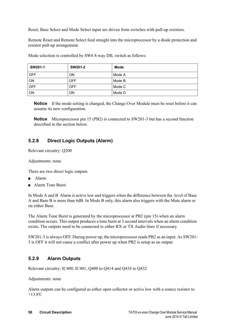
58 Circuit Description TA703-xx-xxxx Change Over Module Service Manual June 2014 © Tait Limited
Reset, Base Select and Mode Select input are driven from switches with pull-up resistors.
Remote Reset and Remote Select feed straight into the microprocessor by a diode protection and resistor pull-up arrangement.
Mode selection is controlled by SW6 8-way DIL switch as follows:
OFF ON Mode A
ON OFF Mode B
OFF OFF Mode C
ON ON Mode D
Notice If the mode setting is changed, the Change Over Module must be reset before it can assume its new configuration.
Notice Microprocessor pin 15 (PB2) is connected to SW201-3 but has a second function described in the section below.
5.2.8 Direct Logic Outputs (Alarm)
Relevant circuitry: Q200
Adjustments: none
There are two direct logic outputs ■ Alarm■ Alarm Tone Burst
In Mode A and B Alarm is active low and triggers when the difference between the level of Base A and Base B is more than 6dB. In Mode B only, this alarm also triggers with the Mute alarm or on either Base.
The Alarm Tone Burst is generated by the microprocessor at PB2 (pin 15) when an alarm condition occurs. This output produces a tone burst at 3 second intervals when an alarm condition exists. The outputs need to be connected to either RX or TX Audio lines if necessary.
SW201-3 is always OFF. During power up, the microprocessor reads PB2 as an input. As SW201-3 is OFF it will not cause a conflict after power up when PB2 is setup as an output.
5.2.9 Alarm Outputs
Relevant circuitry: IC400, IC401, Q400 to Q414 and Q418 to Q432
Adjustments: none
Alarm outputs can be configured as either open collector or active low with a source resistor to +13.8V.
SW201-1 SW201-2 Mode

TA703-xx-xxxx Change Over Module Service Manual Circuit Description 59 June 2014 © Tait Limited
The All Alarm for Base A and Base B has closed contacts in the non-alarm state and can be configured as:■ Dry relay contact to Gnd - All2A switched to Gnd■ Closure of two dry relay contacts - All1A shorts to All2A■ With source resistor to +13.8V, hard wired to All1A
Alarm outputs available:■ All Alarm, activates when any of the standard alarm conditions are met■ Fwd Pwr, activates when the level stays below to minimum set.■ Rev. Pwr, activates when the level exceeds a maximum set■ Mute, activates when the other mute gets active and this one not■ , activates when this is more than 6dB below the other one■ PSU, activates when the level stays below minimum set, typically 10.8V
These alarms are open collector to Gnd with an optional 1k resistor to +13.8V
5.2.10 Battery Alarm
When the battery drops below its preset alarm trigger level both ALL relays - RL400 and RL 401 - start a continuous on-off cycle of 600/600mS. If a power supply then drops below the trigger level the cycle changes to continuous alarm on the relay of the base with the faulty supply (contacts open when alarm raised).
Notice In the non-alarm state the ALL Alarm relays are normally powered up
Notice When no battery is connected, to prevent the Change Over Module from triggering the “low battery” alarm, SW100-3 should be closed connecting the V+ Batt input to the 13.8V supply.

60 Circuit Description TA703-xx-xxxx Change Over Module Service Manual June 2014 © Tait Limited
5.2.11 Signal Polarity
Rx Gate Input Active low
TX Key Output Active low
Rx Mute Input Active low
Fwd Pwr Alarm Input Active high
Rev Pwr Alarm Input Active high
Remote Select Input ‘1’ – Base A; ‘0’ – Base B
Remote Reset Input Active low
alarm Output Active low
CO relay Output Active low
SR_ALL Output select: contact closure, short to Gnd, pull up to +
SR_individual Output active low, select: pull up to +
5.3 Change Over
5.3.1 Change-Over Switches
Relevant circuitry: IC100, IC101, RL100, RL101, RL 102, RL 103, IC102 and Q106
Adjustments: none
The following signals are changed over:■ 2 wire Rx Audio■ 2 wire Tx Audio■ Rx Gate (= Rx Mute)■ Tx-Key (= Tx-Enable)■ Select Base Coaxial Relay
Latching relays are used for all switching. If power disappears from the Change Over Module, the latched relay contacts ensure that all 4 wire plus E&M signalling remains connected to the selected base.
5.3.2 Change Over Control
Latching relays are driven by the microprocessor with two lines for direction (DIR_PC0 and DIR_PC2) and one line to control (CNTRL_PC1). To change over, the control line must be pulsed
Function I/O Comment

TA703-xx-xxxx Change Over Module Service Manual Circuit Description 61 June 2014 © Tait Limited
high for one polling cycle.
low sel Base A: Rx Aud, Rx-Gate, sel Base A Tx Aud, Tx-Key, Coax Relay
high sel Base B: Rx Aud, Rx-Gate, sel Base B Tx Aud, Tx-Key, Coax Relay
Rx/Tx Change-over Relay switches from the remote Tx-Key input
PC1 Direction PC0 ⇑ PC2 ⇑

62 Circuit Description TA703-xx-xxxx Change Over Module Service Manual June 2014 © Tait Limited
5.4 External Connections
5.4.1 PL1 and PL2 15-way D-ranges (Base A and Base B
1 RX Audio + Input transparent
2 RX Audio - Input transparent
3 TX Audio + Input transparent
4 TX Audio - Input transparent
5 RX-Gate Input RX Gate
6 Fwd Pwr Alarm Input Active High
7 TX Key Output Open collector 10mA sink impedance
8 Rev Pwr Alarm Input Active high
9
10 Tx Enable Input Shorted to TX Key
11 Fwd Pwr level Input Output
12 Rev Pwr level Input Output
13 PSU Input PSU monitoring. Optionally to supply power to TA703-xx-xxxx module.
14 Input
15 GND Gnd
5.4.2 PL3 15-way D-range (4 Wire E&M)
This connector is the interface point between the base station system and the remote console. It is wired as follows:
1 Rx-Audio + Transparent
2 Rx Audio - Transparent
3 Tx Audio + Transparent
4 Tx-Audio - Transparent
5 Rx-Gate O/P Active low upon receive of valid carrier
6 Rx-Gate (spare) not used
7 Remote Tx-Key Active low input to transmit
8 V+ Battery Input to Battery Alarm Circuit
9 Combined Audio + Balanced output to voice logger - future development
10 Combined Audio - Balanced output to voice logger - future development
11 Active Displays level of active base
12 Remote Reset (RAC) Driven by open collector 10mA sink capability
13 Alarm Open collector 10mA sink
14 Remote Select High = TX of Base A, Low = TX of Base B.
15 Gnd
Pin Function I/O Comment
Pin Function Description

TA703-xx-xxxx Change Over Module Service Manual Circuit Description 63 June 2014 © Tait Limited
5.4.3 PL4 15-way D-range (Alarm Outputs)
1 contact between pin 1 and pin 2 opens on any alarm activated in Base A
refer to internal links for options on all alarm outputs
2
3 open collector. Active low when Fwd Pwr of Base A fails
4 open collector. Active low when Rev Pwr of Base A fails
5 open collector. Active low when Mute of Base A fails
6 open collector. Active low when of Base A fails
7 open collector. Active low when PSU of Base A fails
8 Gnd
9 contact between pin 9and pin 10 opens on any alarm activated in Base B10
11 open collector. Active low when Fwd Pwr of Base B fails
12 open collector. Active low when Rev Pwr of Base B fails
13 open collector. Active low when Mute of Base B fails
14 open collector. Active low when of Base B fails
15 open collector. Active low when PSU of Base B fails
5.4.4 SK1 25-way D-range (Modem Interface)
This socket interfaces to external equipment and RS-232 for Data Terminal Equipment.
Pin Alarm Comments
Pin Signal Function
1 FRAME GND Earth to Chassis
2 TD Transmitted data - RS-232
3 RD Received data - RS-232
4 N/C
5 N/C
6 N/C
7 SG-GND RS-232 - Ground
8 N/C
9 GND
10 GND
11 N/C
12 V+ OUTFrom optional DC-DC converter13 V+ OUT
14 REMOTE RX LINE +600 Ohm balanced audio from receiver15 REMOTE RX LINE -
16 REMOTE TX LINE +600 Ohm balanced audio to transmitter17 REMOTE TX LINE -
18 RX GATE OUT Copy from active receiver gate O/P
19 REMOTE TX KEY Active low input to key active transmitter
20 N/C

64 Circuit Description TA703-xx-xxxx Change Over Module Service Manual June 2014 © Tait Limited
5.4.5 XLR Plug
This connector provides the power input (13.8V, 1.2A maximum).
1 +ve
2 +ve
3 Ground
4 Ground
21 O/P Analog level from receiver
22 N/C
23 RMT_ SELECT Forces change over to standby transmitter
24 V+ OUTFrom optional DC-DC converter25 V+ OUT
Pin Function
TA703-xx-xxxx Change Over Module Service Manual PCB information 65 June 2014 © Tait Limited
6 PCB information
This part contains information for the Change Over Module Control PCB (IPN 227-70301-07). It contains the following information:■ Introduction■ SMD Parts List (227-70301-07)■ Non-SMD Parts List (227-70301-07)■ PCB Layout (227-70301-07) - top side■ PCB Layout (227-70301-07) - bottom side■ Circuit Diagram (227-70301-07) - page 1 of 2■ Circuit Diagram (227-70301-07) - page 2 of 2■ Circuit Diagram (227-70301-07) - page 3 of 4■ Circuit Diagram (227-70301-07) - page 4 of 4
6.1 Introduction
6.1.1 Parts Lists
The 10 digit numbers (000-00000-00) in the parts lists are ‘internal part numbers’ (IPNs). Your spare parts orders can be handled more efficiently if you quote: equipment type, circuit reference and IPN, along with a brief description of the part. The components listed in the parts lists are divided into two main types: those with a circuit reference (e.g. C201, D106, R121, etc.) and those without (mechanical and miscellaneous). Those with a circuit reference are grouped firstly by PCB, then by circuit designation in numerical order.
Each component entry comprises three or four columns: the circuit reference, variant number (if applicable), IPN and description. A number in the variant column indicates that this particular component is fitted only to that variant. The miscellaneous and mechanical section lists the variant and common parts in IPN order.
6.1.2 Grid Reference Indexes
To assist in locating components and labelled pads on the PCB layouts and circuit diagrams, a component grid reference index has been provided. This index lists the components and pads in alphabetical order, along with the appropriate alphanumeric grid references.
The first digit in the circuit diagram reference is the sheet number, and the last two characters give the location of the component on that sheet. The

66 PCB information TA703-xx-xxxx Change Over Module Service Manual June 2014 © Tait Limited
first digit in the PCB layout reference is a ‘1’ or ‘2’, indicating the top or bottom side layout respectively, and the last two characters give the location of the component on that diagram.
6.1.3 Using CAD Circuit Diagrams
Reading a CAD circuit diagram is similar to reading a road map, in that both have an alphanumeric border. The circuit diagrams in this Manual use letters to represent the horizontal axis, and numbers for the vertical axis. These circuit diagram ‘grid references’ are useful in following a circuit that is spread over two or more sheets. When a line representing part of the circuitry is discontinued, a reference will be given at the end of the line to indicate where the rest of the circuitry is located. The first digit refers to the sheet number (printed on the bottom right hand corner of the CAD diagram) and the last two characters refer to the location on that sheet of the continuation of the circuit (e.g. 1-D4). If more than one line is represented (indicated by a double thickness line), a dot with a reference label will follow the route each individual line represents.

TA703-xx-xxxx Change Over Module Service Manual PCB information 67 June 2014 © Tait Limited
6.2 SMD Parts List (227-70301-07)
Ref IPN Description PCB SchematicC100 015-26100-08 CAP 100N 10% 50V X7R 1:G3 1-J0C101 015-26100-08 CAP 100N 10% 50V X7R 1:C5 1-K0C102 015-26100-08 CAP 100N 10% 50V X7R 1:E5 1-G0C105 016-09100-05 CAP 100U ELEC 25V 20% SIZE 8.5*9.2MM 1:B4 1-P8C105A 016-08100-01 CAP 10U ELEC 16V 4*5.7MM 1:C5 1-Q8C105B 015-26100-08 CAP 100N 10% 50V X7R 1:C5 1-Q8C106 016-09100-05 CAP 100U ELEC 25V 20% SIZE 8.5*9.2MM 1:B5 1-P6C106A 016-08100-01 CAP 10U ELEC 16V 4*5.7MM 1:C5 1-Q6C106B 015-26100-08 CAP 100N 10% 50V X7R 1:C5 1-Q6C110 015-24100-08 CAP 1N0 5% 50V X7R 1:E4 1-Q5C114 015-24100-08 CAP 1N0 5% 50V X7R 1:E5 1-Q4C118 015-24100-08 CAP 1N0 5% 50V X7R 1:R2 1-Q2C120 015-25100-08 CAP 10N 10% 50V X7R 1:G3 1-D6C121 015-25100-08 CAP 10N 10% 50V X7R 1:G3 1-D5C122 015-25100-08 CAP 10N 10% 50V X7R 1:D5 1-D4C123 015-25100-08 CAP 10N 10% 50V X7R 1:C5 1-D4C126 015-23100-01 CAP 100P 5% NPO 50V 1:E6 1-K6C127 015-24100-08 CAP 1N0 5% 50V X7R 1:F6 1-L7C128 015-24100-08 CAP 1N0 5% 50V X7R 1:F6 1-L6C131 016-08100-01 CAP 10U ELEC 16V 4*5.7MM 1:C4 1-R8*C160 016-09220-01 CAP 220U ELEC 35V 10.5MM SQ SMD 1:Q5 1-M1*C161 016-09100-05 CAP 100U ELEC 25V 20% SIZE 8.5*9.2MM 1:P5 1-N1*C162 016-07100-01 CAP 1U0 ELEC 16V 4*5.7MM 1:P6 1-N1*C163 016-09470-01 CAP 470U ELEC 16V 10.5MM SQ SMD 1:R5 1-Q1*C164 016-09100-05 CAP 100U ELEC 25V 20% SIZE 8.5*9.2MM 1:R5 1-Q1*C165 016-07100-01 CAP 1U0 ELEC 16V 4*5.7MM 1:R6 1-Q1C200 015-26100-08 CAP 100N 10% 50V X7R 1:F4 2-K7C201 015-26100-08 CAP 100N 10% 50V X7R 1:C3 2-K0C203 015-26100-08 CAP 100N 10% 50V X7R 1:G4 2-L0C220 015-26100-08 CAP 100N 10% 50V X7R 1:G4 2-G7C221 015-26100-08 CAP 100N 10% 50V X7R 1:G4 2-G6C224 015-24100-08 CAP 1N0 5% 50V X7R 1:F4 2-L7C228 015-24470-08 CAP 4N7 10% 50V X7R 1:B4 2-B6C229 016-08100-01 CAP 10U ELEC 16V 4*5.7MM 1:N3 2-E5C232 015-24470-08 CAP 4N7 10% 50V X7R 1:B4 2-B4C233 016-08100-01 CAP 10U ELEC 16V 4*5.7MM 1:G2 2-E3C237 015-22220-01 CAP 22P 5% NPO 50V 1:F5 2-J3C238 015-22220-01 CAP 22P 5% NPO 50V 1:F4 2-J3C243 016-08100-01 CAP 10U ELEC 16V 4*5.7MM 1:K4 2-P6C244 016-08100-01 CAP 10U ELEC 16V 4*5.7MM 1:K4 2-P6C245 016-08100-01 CAP 10U ELEC 16V 4*5.7MM 1:K4 2-Q6C246 016-08100-01 CAP 10U ELEC 16V 4*5.7MM 1:K4 2-Q6C249 015-24100-08 CAP 1N0 5% 50V X7R 1:G4 2-N4C253 015-24470-08 CAP 4N7 10% 50V X7R 1:A4 2-B2C254 016-08100-01 CAP 10U ELEC 16V 4*5.7MM 1:N3 2-E2C257 015-24470-08 CAP 4N7 10% 50V X7R 1:B4 2-B1C258 016-08100-01 CAP 10U ELEC 16V 4*5.7MM 1:F2 2-E0

68 PCB information TA703-xx-xxxx Change Over Module Service Manual June 2014 © Tait Limited
C320 015-24100-08 CAP 1N0 5% 50V X7R 1:F6 3-A6C321 015-25470-08 CAP 47N 10% 50V X7R 1:F6 3-B6C322 015-23100-01 CAP 100P 5% NPO 50V 1:G6 3-C8C327 015-24100-08 CAP 1N0 5% 50V X7R 1:E2 3-J8C328 015-24100-08 CAP 1N0 5% 50V X7R 1:E2 3-J6C331 015-24100-08 CAP 1N0 5% 50V X7R 1:F6 3-A4C332 015-25470-08 CAP 47N 10% 50V X7R 1:G6 3-B4C333 015-23100-01 CAP 100P 5% NPO 50V 1:G5 3-C5C335 016-07100-01 CAP 1U0 ELEC 16V 4*5.7MM 1:G5 3-E3C338 015-24100-08 CAP 1N0 5% 50V X7R 1:L2 3-J5C339 015-24100-08 CAP 1N0 5% 50V X7R 1:L2 3-J3C400 015-26100-08 CAP 100N 10% 50V X7R 1:J4 4-D9C401 015-26100-08 CAP 100N 10% 50V X7R 1:N3 4-D4C420 015-24100-08 CAP 1N0 5% 50V X7R 1:K4 4-H8C421 015-24100-08 CAP 1N0 5% 50V X7R 1:J4 4-G7C422 015-24100-08 CAP 1N0 5% 50V X7R 1:J4 4-J6C423 015-24100-08 CAP 1N0 5% 50V X7R 1:J4 4-L6C424 015-24100-08 CAP 1N0 5% 50V X7R 1:J3 4-M5C425 015-24100-08 CAP 1N0 5% 50V X7R 1:J3 4-P5C429 015-24100-08 CAP 1N0 5% 50V X7R 1:H6 4-Q7C430 015-24100-08 CAP 1N0 5% 50V X7R 1:H6 4-Q7C431 015-24100-08 CAP 1N0 5% 50V X7R 1:H6 4-Q6C432 015-24100-08 CAP 1N0 5% 50V X7R 1:H6 4-Q6C433 015-24100-08 CAP 1N0 5% 50V X7R 1:G6 4-Q5C436 015-24100-08 CAP 1N0 5% 50V X7R 1:N4 4-H3C437 015-24100-08 CAP 1N0 5% 50V X7R 1:M4 4-G2C438 015-24100-08 CAP 1N0 5% 50V X7R 1:M4 4-J2C439 015-24100-08 CAP 1N0 5% 50V X7R 1:M4 4-L1C440 015-24100-08 CAP 1N0 5% 50V X7R 1:M3 4-M1C441 015-24100-08 CAP 1N0 5% 50V X7R 1:M3 4-P0C445 015-24100-08 CAP 1N0 5% 50V X7R 1:H6 4-Q3C446 015-24100-08 CAP 1N0 5% 50V X7R 1:H6 4-Q2C447 015-24100-08 CAP 1N0 5% 50V X7R 1:H6 4-Q1C448 015-24100-08 CAP 1N0 5% 50V X7R 1:H6 4-Q1C449 015-24100-08 CAP 1N0 5% 50V X7R 1:G6 4-Q0D100 001-10011-74 DIODE MRA4004T3 PWR RECTIFIER 400V 1A CASE 403B-01 1:C6 1-D7D101 001-10011-74 DIODE MRA4004T3 PWR RECTIFIER 400V 1A CASE 403B-01 1:C6 1-D6D102 001-10011-74 DIODE MRA4004T3 PWR RECTIFIER 400V 1A CASE 403B-01 1:D5 1-D5D103 001-10011-74 DIODE MRA4004T3 PWR RECTIFIER 400V 1A CASE 403B-01 1:D5 1-D4D107 001-10011-74 DIODE MRA4004T3 PWR RECTIFIER 400V 1A CASE 403B-01 1:P6 1-J3D108 001-10011-74 DIODE MRA4004T3 PWR RECTIFIER 400V 1A CASE 403B-01 1:P6 1-L4D109 001-10011-74 DIODE MRA4004T3 PWR RECTIFIER 400V 1A CASE 403B-01 1:E5 1-Q5D110 001-10011-74 Diode SMD MRA4004T3 1A/400v 1:E5 1-Q4D112 001-10011-74 DIODE MRA4004T3 PWR RECTIFIER 400V 1A CASE 403B-01 1:E5 1-Q4D202 001-10000-99 DIODE BAV99 DUAL SW (PIN 3 IS ANODE/CATH) 1:F4 2-L7D205 001-10000-99 DIODE BAV99 DUAL SW (PIN 3 IS ANODE/CATH) 1:G4 2-M4D210 001-10000-99 DIODE BAV99 DUAL SW (PIN 3 IS ANODE/CATH) 1:C4 2-G2D211 001-10000-99 DIODE BAV99 DUAL SW (PIN 3 IS ANODE/CATH) 1:B4 2-G0D300 008-10065-00 LED HSMG-C650 GREEN SMD 1:E4 3-F8D301 008-10065-00 LED HSMG-C650 GREEN SMD 1:F4 3-G8
Ref IPN Description PCB Schematic
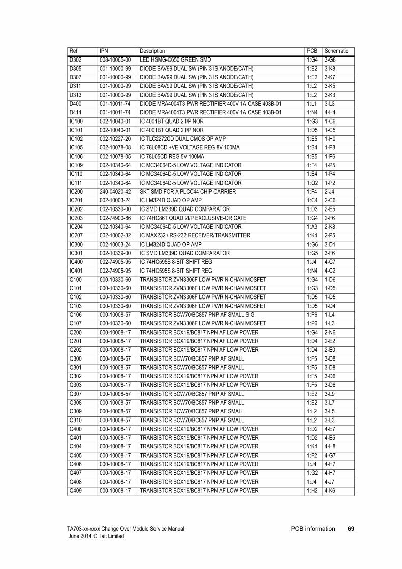
TA703-xx-xxxx Change Over Module Service Manual PCB information 69 June 2014 © Tait Limited
D302 008-10065-00 LED HSMG-C650 GREEN SMD 1:G4 3-G8D305 001-10000-99 DIODE BAV99 DUAL SW (PIN 3 IS ANODE/CATH) 1:E2 3-K8D307 001-10000-99 DIODE BAV99 DUAL SW (PIN 3 IS ANODE/CATH) 1:E2 3-K7D311 001-10000-99 DIODE BAV99 DUAL SW (PIN 3 IS ANODE/CATH) 1:L2 3-K5D313 001-10000-99 DIODE BAV99 DUAL SW (PIN 3 IS ANODE/CATH) 1:L2 3-K3D400 001-10011-74 DIODE MRA4004T3 PWR RECTIFIER 400V 1A CASE 403B-01 1:L1 3-L3D414 001-10011-74 DIODE MRA4004T3 PWR RECTIFIER 400V 1A CASE 403B-01 1:N4 4-H4IC100 002-10040-01 IC 4001BT QUAD 2 I/P NOR 1:G3 1-C6IC101 002-10040-01 IC 4001BT QUAD 2 I/P NOR 1:D5 1-C5IC102 002-10227-20 IC TLC2272CD DUAL CMOS OP AMP 1:E5 1-H0IC105 002-10078-08 IC 78L08CD +VE VOLTAGE REG 8V 100MA 1:B4 1-P8IC106 002-10078-05 IC 78L05CD REG 5V 100MA 1:B5 1-P6IC109 002-10340-64 IC MC34064D-5 LOW VOLTAGE INDICATOR 1:F4 1-P5IC110 002-10340-64 IC MC34064D-5 LOW VOLTAGE INDICATOR 1:E4 1-P4IC111 002-10340-64 IC MC34064D-5 LOW VOLTAGE INDICATOR 1:Q2 1-P2IC200 240-04020-42 SKT SMD FOR A PLCC44 CHIP CARRIER 1:F4 2-J4IC201 002-10003-24 IC LM324D QUAD OP AMP 1:C4 2-C6IC202 002-10339-00 IC SMD LM339D QUAD COMPARATOR 1:D3 2-E5IC203 002-74900-86 IC 74HC86T QUAD 2I/P EXCLUSIVE-OR GATE 1:G4 2-F6IC204 002-10340-64 IC MC34064D-5 LOW VOLTAGE INDICATOR 1:A3 2-K8IC207 002-10002-32 IC MAX232 / RS-232 RECEIVER/TRANSMITTER 1:K4 2-P5IC300 002-10003-24 IC LM324D QUAD OP AMP 1:G6 3-D1IC301 002-10339-00 IC SMD LM339D QUAD COMPARATOR 1:G5 3-F6IC400 002-74905-95 IC 74HC595S 8-BIT SHIFT REG 1:J4 4-C7IC401 002-74905-95 IC 74HC595S 8-BIT SHIFT REG 1:N4 4-C2Q100 000-10330-60 TRANSISTOR ZVN3306F LOW PWR N-CHAN MOSFET 1:G4 1-D6Q101 000-10330-60 TRANSISTOR ZVN3306F LOW PWR N-CHAN MOSFET 1:G3 1-D5Q102 000-10330-60 TRANSISTOR ZVN3306F LOW PWR N-CHAN MOSFET 1:D5 1-D5Q103 000-10330-60 TRANSISTOR ZVN3306F LOW PWR N-CHAN MOSFET 1:D5 1-D4Q106 000-10008-57 TRANSISTOR BCW70/BC857 PNP AF SMALL SIG 1:P6 1-L4Q107 000-10330-60 TRANSISTOR ZVN3306F LOW PWR N-CHAN MOSFET 1:P6 1-L3Q200 000-10008-17 TRANSISTOR BCX19/BC817 NPN AF LOW POWER 1:G4 2-N6Q201 000-10008-17 TRANSISTOR BCX19/BC817 NPN AF LOW POWER 1:D4 2-E2Q202 000-10008-17 TRANSISTOR BCX19/BC817 NPN AF LOW POWER 1:D4 2-E0Q300 000-10008-57 TRANSISTOR BCW70/BC857 PNP AF SMALL 1:F5 3-D8Q301 000-10008-57 TRANSISTOR BCW70/BC857 PNP AF SMALL 1:F5 3-D8Q302 000-10008-17 TRANSISTOR BCX19/BC817 NPN AF LOW POWER 1:F5 3-D6Q303 000-10008-17 TRANSISTOR BCX19/BC817 NPN AF LOW POWER 1:F5 3-D6Q307 000-10008-57 TRANSISTOR BCW70/BC857 PNP AF SMALL 1:E2 3-L9Q308 000-10008-57 TRANSISTOR BCW70/BC857 PNP AF SMALL 1:E2 3-L7Q309 000-10008-57 TRANSISTOR BCW70/BC857 PNP AF SMALL 1:L2 3-L5Q310 000-10008-57 TRANSISTOR BCW70/BC857 PNP AF SMALL 1:L2 3-L3Q400 000-10008-17 TRANSISTOR BCX19/BC817 NPN AF LOW POWER 1:D2 4-E7Q401 000-10008-17 TRANSISTOR BCX19/BC817 NPN AF LOW POWER 1:D2 4-E5Q404 000-10008-17 TRANSISTOR BCX19/BC817 NPN AF LOW POWER 1:K4 4-H8Q405 000-10008-17 TRANSISTOR BCX19/BC817 NPN AF LOW POWER 1:F2 4-G7Q406 000-10008-17 TRANSISTOR BCX19/BC817 NPN AF LOW POWER 1:J4 4-H7Q407 000-10008-17 TRANSISTOR BCX19/BC817 NPN AF LOW POWER 1:G2 4-H7Q408 000-10008-17 TRANSISTOR BCX19/BC817 NPN AF LOW POWER 1:J4 4-J7Q409 000-10008-17 TRANSISTOR BCX19/BC817 NPN AF LOW POWER 1:H2 4-K6
Ref IPN Description PCB Schematic
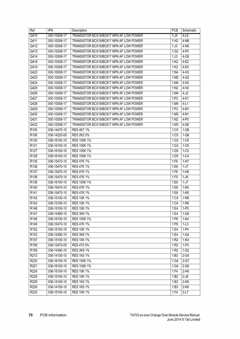
70 PCB information TA703-xx-xxxx Change Over Module Service Manual June 2014 © Tait Limited
Q410 000-10008-17 TRANSISTOR BCX19/BC817 NPN AF LOW POWER 1:J4 4-L6Q411 000-10008-17 TRANSISTOR BCX19/BC817 NPN AF LOW POWER 1:H2 4-M6Q412 000-10008-17 TRANSISTOR BCX19/BC817 NPN AF LOW POWER 1:J3 4-N6Q413 000-10008-17 TRANSISTOR BCX19/BC817 NPN AF LOW POWER 1:G2 4-P5Q414 000-10008-17 TRANSISTOR BCX19/BC817 NPN AF LOW POWER 1:J3 4-Q5Q418 000-10008-17 TRANSISTOR BCX19/BC817 NPN AF LOW POWER 1:K2 4-E2Q419 000-10008-17 TRANSISTOR BCX19/BC817 NPN AF LOW POWER 1:K2 4-E0Q422 000-10008-17 TRANSISTOR BCX19/BC817 NPN AF LOW POWER 1:N4 4-H3Q423 000-10008-17 TRANSISTOR BCX19/BC817 NPN AF LOW POWER 1:M2 4-G2Q424 000-10008-17 TRANSISTOR BCX19/BC817 NPN AF LOW POWER 1:M4 4-H2Q425 000-10008-17 TRANSISTOR BCX19/BC817 NPN AF LOW POWER 1:N2 4-H2Q426 000-10008-17 TRANSISTOR BCX19/BC817 NPN AF LOW POWER 1:M4 4-J2Q427 000-10008-17 TRANSISTOR BCX19/BC817 NPN AF LOW POWER 1:P2 4-K1Q428 000-10008-17 TRANSISTOR BCX19/BC817 NPN AF LOW POWER 1:M4 4-L1Q429 000-10008-17 TRANSISTOR BCX19/BC817 NPN AF LOW POWER 1:P2 4-M1Q430 000-10008-17 TRANSISTOR BCX19/BC817 NPN AF LOW POWER 1:M3 4-N1Q431 000-10008-17 TRANSISTOR BCX19/BC817 NPN AF LOW POWER 1:N2 4-P0Q432 000-10008-17 TRANSISTOR BCX19/BC817 NPN AF LOW POWER 1:M3 4-Q0R105 036-14470-10 RES 4K7 1% 1:C5 1-Q8R106 036-14220-00 RES 2K2 5% 1:C5 1-Q6R120 036-16100-10 RES 100K 1% 1:G3 1-C6R121 036-16100-10 RES 100K 1% 1:G3 1-C6R127 036-16100-10 RES 100K 1% 1:D5 1-C5R128 036-16100-10 RES 100K 1% 1:D5 1-C4R135 036-15470-10 RES 47K 1% 1:F6 1-H7R136 036-15470-10 RES 47K 1% 1:E6 1-J7R137 036-15470-10 RES 47K 1% 1:F6 1-H6R138 036-15470-10 RES 47K 1% 1:F5 1-J6R139 036-16100-10 RES 100K 1% 1:E6 1-J7R140 036-15470-10 RES 47K 1% 1:E6 1-K6R141 036-15470-10 RES 47K 1% 1:E6 1-K6R142 036-15100-10 RES 10K 1% 1:C4 1-R8R143 036-15100-10 RES 10K 1% 1:C4 1-R8R146 036-15100-10 RES 10K 1% 1:E4 1-P5R147 036-14390-10 RES 3K9 1% 1:E4 1-Q5R148 036-16100-10 RES 100K 1% 1:P6 1-K4R149 036-15470-10 RES 47K 1% 1:P6 1-L3R152 036-15100-10 RES 10K 1% 1:E4 1-P4R153 036-14390-10 RES 3K9 1% 1:E4 1-Q4R157 036-15100-10 RES 10K 1% 1:R2 1-N3R158 036-13470-00 RES 470 5% 1:R2 1-P3R159 036-14390-10 RES 3K9 1% 1:R2 1-Q2R213 036-14100-10 RES 1K0 1% 1:B3 2-G4R220 036-16100-10 RES 100K 1% 1:G4 2-G7R221 036-16100-10 RES 100K 1% 1:G4 2-G6R224 036-15100-10 RES 10K 1% 1:F4 2-H6R228 036-15100-10 RES 10K 1% 1:B2 2-J8R229 036-14100-10 RES 1K0 1% 1:B3 2-K8R230 036-14150-10 RES 1K5 1% 1:B3 2-K8R233 036-15100-10 RES 10K 1% 1:F4 2-L7
Ref IPN Description PCB Schematic

TA703-xx-xxxx Change Over Module Service Manual PCB information 71 June 2014 © Tait Limited
R234 036-15100-10 RES 10K 1% 1:F4 2-L6R235 036-15100-10 RES 10K 1% 1:F4 2-L6R236 036-15100-10 RES 10K 1% 1:F4 2-L6R237 036-15100-10 RES 10K 1% 1:G4 2-M6*R238 036-15220-00 RES 22K 5% 1:G4 2-N7R239 036-15220-00 RES 22K 5% 1:G4 2-M6R243 036-15470-10 RES 47K 1% 1:B4 2-C6R244 036-15470-10 RES 47K 1% 1:B4 2-C6R245 036-15220-00 RES 22K 5% 1:C3 2-C5R246 036-16100-10 RES 100K 1% 1:C3 2-D5R247 036-16100-10 RES 100K 1% 1:C3 2-D6R248 036-16220-00 RES 220K 5% 1:D3 2-E6R249 036-15100-10 RES 10K 1% 1:D4 2-E6R250 036-15100-10 RES 10K 1% 1:B3 2-F5R251 036-15100-10 RES 10K 1% 1:B3 2-G5R252 036-15100-10 RES 10K 1% 1:B3 2-G5R255 036-15470-10 RES 47K 1% 1:A4 2-C4R256 036-15470-10 RES 47K 1% 1:B4 2-C4R257 036-15220-00 RES 22K 5% 1:C4 2-C4R258 036-16100-10 RES 100K 1% 1:C4 2-D4R259 036-16100-10 RES 100K 1% 1:C3 2-D4R260 036-16220-00 RES 220K 5% 1:D3 2-E4R261 036-15100-10 RES 10K 1% 1:D4 2-E4R264 036-17220-00 RES 2M2 5% 1:F4 2-J4R266 036-15100-10 RES 10K 1% 1:B2 2-N5R269 036-15220-00 RES 22K 5% 1:G4 2-M4R270 036-15100-10 RES 10K 1% 1:D4 2-F2R271 036-15270-10 RES 27K 1% 1:D4 2-F2R272 036-15470-10 RES 47K 1% 1:B4 2-C2R273 036-15470-10 RES 47K 1% 1:B4 2-C3R274 036-16100-10 RES 100K 1% 1:C4 2-C2R275 036-16100-10 RES 100K 1% 1:C4 2-D2R276 036-16100-10 RES 100K 1% 1:C4 2-D3R277 036-16220-00 RES 220K 5% 1:D4 2-E3R278 036-15100-10 RES 10K 1% 1:D4 2-F3R279 036-15100-10 RES 10K 1% 1:D4 2-F3R280 036-15100-10 RES 10K 1% 1:D4 2-F0R281 036-15270-10 RES 27K 1% 1:D4 2-F0R283 036-15470-10 RES 47K 1% 1:B4 2-C1R284 036-15470-10 RES 47K 1% 1:B4 2-C1R285 036-16100-10 RES 100K 1% 1:C4 2-C0R286 036-16100-10 RES 100K 1% 1:C4 2-D0R287 036-16100-10 RES 100K 1% 1:C4 2-D1R288 036-16220-00 RES 220K 5% 1:C4 2-E1R289 036-15100-10 RES 10K 1% 1:D4 2-F1R290 036-15100-10 RES 10K 1% 1:D4 2-F1R320 036-14470-10 RES 4K7 1% 1:F5 3-B7R321 036-16220-00 RES 220K 5% 1:F6 3-B7R322 036-16220-00 RES 220K 5% 1:G6 3-C7R323 036-15470-10 RES 47K 1% 1:F6 3-B7
Ref IPN Description PCB Schematic
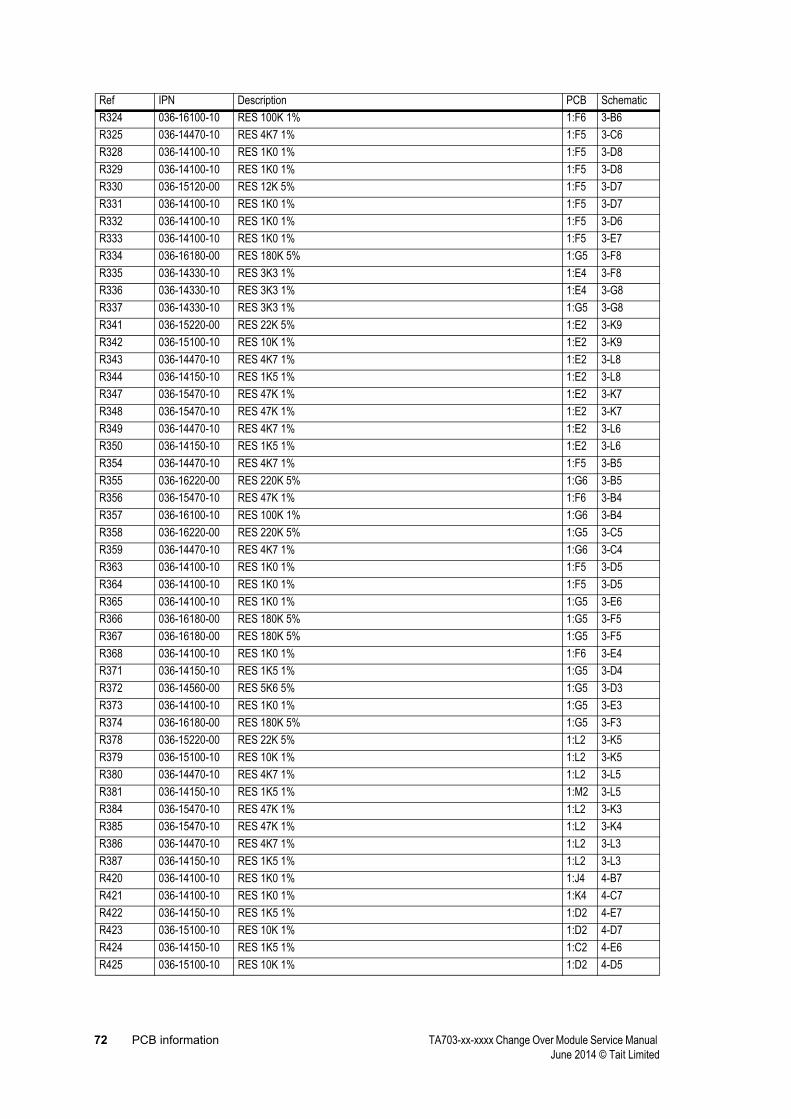
72 PCB information TA703-xx-xxxx Change Over Module Service Manual June 2014 © Tait Limited
R324 036-16100-10 RES 100K 1% 1:F6 3-B6R325 036-14470-10 RES 4K7 1% 1:F5 3-C6R328 036-14100-10 RES 1K0 1% 1:F5 3-D8R329 036-14100-10 RES 1K0 1% 1:F5 3-D8R330 036-15120-00 RES 12K 5% 1:F5 3-D7R331 036-14100-10 RES 1K0 1% 1:F5 3-D7R332 036-14100-10 RES 1K0 1% 1:F5 3-D6R333 036-14100-10 RES 1K0 1% 1:F5 3-E7R334 036-16180-00 RES 180K 5% 1:G5 3-F8R335 036-14330-10 RES 3K3 1% 1:E4 3-F8R336 036-14330-10 RES 3K3 1% 1:E4 3-G8R337 036-14330-10 RES 3K3 1% 1:G5 3-G8R341 036-15220-00 RES 22K 5% 1:E2 3-K9R342 036-15100-10 RES 10K 1% 1:E2 3-K9R343 036-14470-10 RES 4K7 1% 1:E2 3-L8R344 036-14150-10 RES 1K5 1% 1:E2 3-L8R347 036-15470-10 RES 47K 1% 1:E2 3-K7R348 036-15470-10 RES 47K 1% 1:E2 3-K7R349 036-14470-10 RES 4K7 1% 1:E2 3-L6R350 036-14150-10 RES 1K5 1% 1:E2 3-L6R354 036-14470-10 RES 4K7 1% 1:F5 3-B5R355 036-16220-00 RES 220K 5% 1:G6 3-B5R356 036-15470-10 RES 47K 1% 1:F6 3-B4R357 036-16100-10 RES 100K 1% 1:G6 3-B4R358 036-16220-00 RES 220K 5% 1:G5 3-C5R359 036-14470-10 RES 4K7 1% 1:G6 3-C4R363 036-14100-10 RES 1K0 1% 1:F5 3-D5R364 036-14100-10 RES 1K0 1% 1:F5 3-D5R365 036-14100-10 RES 1K0 1% 1:G5 3-E6R366 036-16180-00 RES 180K 5% 1:G5 3-F5R367 036-16180-00 RES 180K 5% 1:G5 3-F5R368 036-14100-10 RES 1K0 1% 1:F6 3-E4R371 036-14150-10 RES 1K5 1% 1:G5 3-D4R372 036-14560-00 RES 5K6 5% 1:G5 3-D3R373 036-14100-10 RES 1K0 1% 1:G5 3-E3R374 036-16180-00 RES 180K 5% 1:G5 3-F3R378 036-15220-00 RES 22K 5% 1:L2 3-K5R379 036-15100-10 RES 10K 1% 1:L2 3-K5R380 036-14470-10 RES 4K7 1% 1:L2 3-L5R381 036-14150-10 RES 1K5 1% 1:M2 3-L5R384 036-15470-10 RES 47K 1% 1:L2 3-K3R385 036-15470-10 RES 47K 1% 1:L2 3-K4R386 036-14470-10 RES 4K7 1% 1:L2 3-L3R387 036-14150-10 RES 1K5 1% 1:L2 3-L3R420 036-14100-10 RES 1K0 1% 1:J4 4-B7R421 036-14100-10 RES 1K0 1% 1:K4 4-C7R422 036-14150-10 RES 1K5 1% 1:D2 4-E7R423 036-15100-10 RES 10K 1% 1:D2 4-D7R424 036-14150-10 RES 1K5 1% 1:C2 4-E6R425 036-15100-10 RES 10K 1% 1:D2 4-D5
Ref IPN Description PCB Schematic
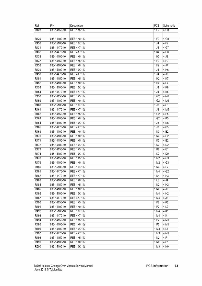
TA703-xx-xxxx Change Over Module Service Manual PCB information 73 June 2014 © Tait Limited
R428 036-14150-10 RES 1K5 1% 1:F2 4-G8
R429 036-14100-10 RES 1K0 1% 1:F2 4-G8R430 036-15100-10 RES 10K 1% 1:J4 4-F7R431 036-14470-10 RES 4K7 1% 1:J4 4-G7R432 036-14470-10 RES 4K7 1% 1:K4 4-H8R433 036-14100-10 RES 1K0 1% 1:H3 4-J9R437 036-14150-10 RES 1K5 1% 1:F2 4-H7R438 036-14100-10 RES 1K0 1% 1:F2 4-J7R439 036-15100-10 RES 10K 1% 1:J4 4-H6R450 036-14470-10 RES 4K7 1% 1:J4 4-J6R451 036-14150-10 RES 1K5 1% 1:H2 4-K7R452 036-14100-10 RES 1K0 1% 1:H2 4-L7R453 036-15100-10 RES 10K 1% 1:J4 4-K6R454 036-14470-10 RES 4K7 1% 1:J4 4-K6R458 036-14150-10 RES 1K5 1% 1:G2 4-M6R459 036-14100-10 RES 1K0 1% 1:G2 4-M6R460 036-15100-10 RES 10K 1% 1:J3 4-L5R461 036-14470-10 RES 4K7 1% 1:J3 4-M5R462 036-14150-10 RES 1K5 1% 1:G2 4-P5R463 036-14100-10 RES 1K0 1% 1:G2 4-P5R464 036-15100-10 RES 10K 1% 1:J3 4-N5R465 036-14470-10 RES 4K7 1% 1:J3 4-P5R469 036-14100-10 RES 1K0 1% 1:N3 4-B2R470 036-14100-10 RES 1K0 1% 1:N4 4-C2R471 036-14150-10 RES 1K5 1% 1:K2 4-E2R472 036-15100-10 RES 10K 1% 1:K2 4-D2R473 036-14150-10 RES 1K5 1% 1:K2 4-E1R474 036-15100-10 RES 10K 1% 1:K2 4-D0R478 036-14150-10 RES 1K5 1% 1:M2 4-G3R479 036-14100-10 RES 1K0 1% 1:M2 4-G3R480 036-15100-10 RES 10K 1% 1:N4 4-F2R481 036-14470-10 RES 4K7 1% 1:M4 4-G2R482 036-14470-10 RES 4K7 1% 1:N4 4-H3R483 036-14100-10 RES 1K0 1% 1:L3 4-J4R484 036-14150-10 RES 1K5 1% 1:N2 4-H2R485 036-14100-10 RES 1K0 1% 1:N2 4-J2R486 036-15100-10 RES 10K 1% 1:M4 4-H2R487 036-14470-10 RES 4K7 1% 1:M4 4-J2R490 036-14150-10 RES 1K5 1% 1:P2 4-K2R491 036-14100-10 RES 1K0 1% 1:P2 4-L2R492 036-15100-10 RES 10K 1% 1:M4 4-K1R493 036-14470-10 RES 4K7 1% 1:M4 4-K1R494 036-14150-10 RES 1K5 1% 1:P2 4-M1R495 036-14100-10 RES 1K0 1% 1:P2 4-M1R496 036-15100-10 RES 10K 1% 1:M3 4-L1R497 036-14470-10 RES 4K7 1% 1:M3 4-M1R498 036-14150-10 RES 1K5 1% 1:N2 4-P1R499 036-14100-10 RES 1K0 1% 1:N2 4-P1R500 036-15100-10 RES 10K 1% 1:M3 4-N0
Ref IPN Description PCB Schematic

74 PCB information TA703-xx-xxxx Change Over Module Service Manual June 2014 © Tait Limited
R501 036-14470-10 RES 4K7 1% 1:M3 4-P0RL400 237-10010-00 RLY DPDT 1-2A/12V DIL 10PIN SMD AS-12W-K-B05 1:K3 4-K0RL401 237-10010-00 RLY DPDT 1-2A/12V DIL 10PIN SMD AS-12W-K-B05 1:N3 4-K4RV300 042-04500-05 TRIM POT 5K +/-25% 5MM SQUARE SMD CERMET 1:F6 3-B7RV301 042-04500-05 TRIM POT 5K +/-25% 5MM SQUARE SMD CERMET 1:G5 3-B5SW100 230-10010-44 SW X 8 SPST 1:D6 1-F0SW201 230-10010-44 SW X 8 SPST 1:B3 2-F0SW400 230-10010-44 SW X 8 SPST 1:H3 4-M6SW401 230-10010-44 SW X 8 SPST 1:M3 4-J2 X200 274-10004-00 CRYSTAL 4.032MHZ +-10PPM 1:F4 2-J4
Ref IPN Description PCB Schematic
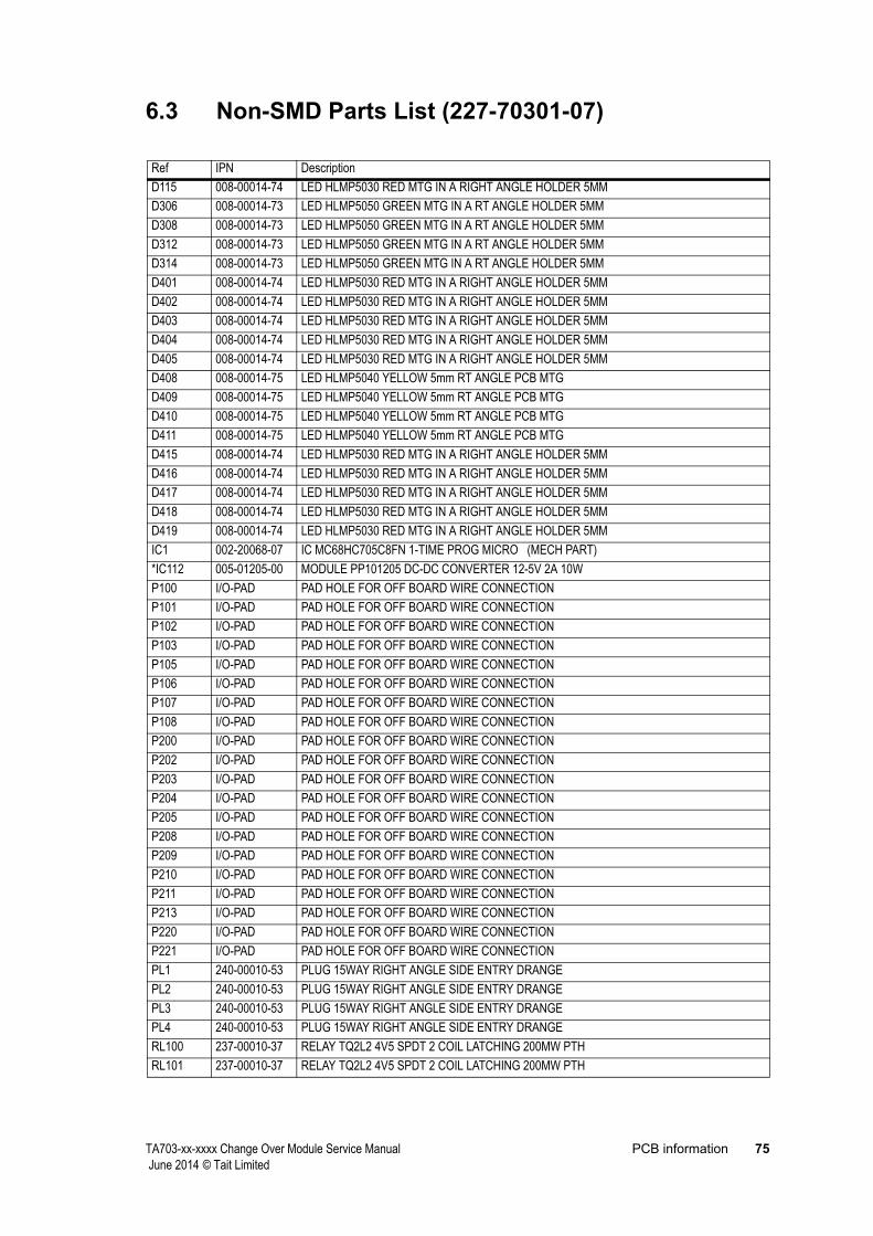
TA703-xx-xxxx Change Over Module Service Manual PCB information 75 June 2014 © Tait Limited
6.3 Non-SMD Parts List (227-70301-07)
Ref IPN DescriptionD115 008-00014-74 LED HLMP5030 RED MTG IN A RIGHT ANGLE HOLDER 5MMD306 008-00014-73 LED HLMP5050 GREEN MTG IN A RT ANGLE HOLDER 5MMD308 008-00014-73 LED HLMP5050 GREEN MTG IN A RT ANGLE HOLDER 5MMD312 008-00014-73 LED HLMP5050 GREEN MTG IN A RT ANGLE HOLDER 5MMD314 008-00014-73 LED HLMP5050 GREEN MTG IN A RT ANGLE HOLDER 5MMD401 008-00014-74 LED HLMP5030 RED MTG IN A RIGHT ANGLE HOLDER 5MMD402 008-00014-74 LED HLMP5030 RED MTG IN A RIGHT ANGLE HOLDER 5MMD403 008-00014-74 LED HLMP5030 RED MTG IN A RIGHT ANGLE HOLDER 5MMD404 008-00014-74 LED HLMP5030 RED MTG IN A RIGHT ANGLE HOLDER 5MMD405 008-00014-74 LED HLMP5030 RED MTG IN A RIGHT ANGLE HOLDER 5MMD408 008-00014-75 LED HLMP5040 YELLOW 5mm RT ANGLE PCB MTGD409 008-00014-75 LED HLMP5040 YELLOW 5mm RT ANGLE PCB MTGD410 008-00014-75 LED HLMP5040 YELLOW 5mm RT ANGLE PCB MTGD411 008-00014-75 LED HLMP5040 YELLOW 5mm RT ANGLE PCB MTGD415 008-00014-74 LED HLMP5030 RED MTG IN A RIGHT ANGLE HOLDER 5MMD416 008-00014-74 LED HLMP5030 RED MTG IN A RIGHT ANGLE HOLDER 5MMD417 008-00014-74 LED HLMP5030 RED MTG IN A RIGHT ANGLE HOLDER 5MMD418 008-00014-74 LED HLMP5030 RED MTG IN A RIGHT ANGLE HOLDER 5MMD419 008-00014-74 LED HLMP5030 RED MTG IN A RIGHT ANGLE HOLDER 5MMIC1 002-20068-07 IC MC68HC705C8FN 1-TIME PROG MICRO (MECH PART)*IC112 005-01205-00 MODULE PP101205 DC-DC CONVERTER 12-5V 2A 10WP100 I/O-PAD PAD HOLE FOR OFF BOARD WIRE CONNECTIONP101 I/O-PAD PAD HOLE FOR OFF BOARD WIRE CONNECTIONP102 I/O-PAD PAD HOLE FOR OFF BOARD WIRE CONNECTIONP103 I/O-PAD PAD HOLE FOR OFF BOARD WIRE CONNECTIONP105 I/O-PAD PAD HOLE FOR OFF BOARD WIRE CONNECTIONP106 I/O-PAD PAD HOLE FOR OFF BOARD WIRE CONNECTIONP107 I/O-PAD PAD HOLE FOR OFF BOARD WIRE CONNECTIONP108 I/O-PAD PAD HOLE FOR OFF BOARD WIRE CONNECTIONP200 I/O-PAD PAD HOLE FOR OFF BOARD WIRE CONNECTIONP202 I/O-PAD PAD HOLE FOR OFF BOARD WIRE CONNECTIONP203 I/O-PAD PAD HOLE FOR OFF BOARD WIRE CONNECTIONP204 I/O-PAD PAD HOLE FOR OFF BOARD WIRE CONNECTIONP205 I/O-PAD PAD HOLE FOR OFF BOARD WIRE CONNECTIONP208 I/O-PAD PAD HOLE FOR OFF BOARD WIRE CONNECTIONP209 I/O-PAD PAD HOLE FOR OFF BOARD WIRE CONNECTIONP210 I/O-PAD PAD HOLE FOR OFF BOARD WIRE CONNECTIONP211 I/O-PAD PAD HOLE FOR OFF BOARD WIRE CONNECTIONP213 I/O-PAD PAD HOLE FOR OFF BOARD WIRE CONNECTIONP220 I/O-PAD PAD HOLE FOR OFF BOARD WIRE CONNECTIONP221 I/O-PAD PAD HOLE FOR OFF BOARD WIRE CONNECTIONPL1 240-00010-53 PLUG 15WAY RIGHT ANGLE SIDE ENTRY DRANGEPL2 240-00010-53 PLUG 15WAY RIGHT ANGLE SIDE ENTRY DRANGEPL3 240-00010-53 PLUG 15WAY RIGHT ANGLE SIDE ENTRY DRANGEPL4 240-00010-53 PLUG 15WAY RIGHT ANGLE SIDE ENTRY DRANGERL100 237-00010-37 RELAY TQ2L2 4V5 SPDT 2 COIL LATCHING 200MW PTHRL101 237-00010-37 RELAY TQ2L2 4V5 SPDT 2 COIL LATCHING 200MW PTH

76 PCB information TA703-xx-xxxx Change Over Module Service Manual June 2014 © Tait Limited
RL102 237-00010-37 RELAY TQ2L2 4V5 SPDT 2 COIL LATCHING 200MW PTHRL103 237-00010-37 RELAY TQ2L2 4V5 SPDT 2 COIL LATCHING 200MW PTHRV100 044-05100-01 POT 10K LIN 15 TURNS COPAL CT-20P SIDE ADJUSTRV101 044-05100-01 POT 10K LIN 15 TURNS COPAL CT-20P SIDE ADJUSTRV102 044-05100-01 POT 10K LIN 15 TURNS COPAL CT-20P SIDE ADJUSTRV203 044-05100-01 POT 10K LIN 15 TURNS COPAL CT-20P SIDE ADJUSTRV204 044-05100-01 POT 10K LIN 15 TURNS COPAL CT-20P SIDE ADJUSTRV205 044-05100-01 POT 10K LIN 15 TURNS COPAL CT-20P SIDE ADJUSTRV206 044-05100-01 POT 10K LIN 15 TURNS COPAL CT-20P SIDE ADJUSTSK1 240-02010-59 SOCKET 25WAY RIGHT ANGLE SIDE ENTRY DRANGESW200 232-00010-26 SWITCH SPDT PUSH MOMENTARY RIGHT ANGLESW202 230-00010-30 SWITCH SPDT TOGGLE RT ANGLE PCB MTGTP300 I/O-PAD PAD HOLE FOR OFF BOARD WIRE CONNECTIONTP301 I/O-PAD PAD HOLE FOR OFF BOARD WIRE CONNECTIONTP302 I/O-PAD PAD HOLE FOR OFF BOARD WIRE CONNECTIONTP305 I/O-PAD PAD HOLE FOR OFF BOARD WIRE CONNECTIONTP310 I/O-PAD PAD HOLE FOR OFF BOARD WIRE CONNECTIONTP311 I/O-PAD PAD HOLE FOR OFF BOARD WIRE CONNECTION
Ref IPN Description
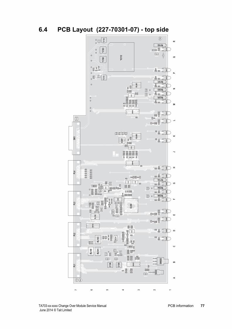
TA703-xx-xxxx Change Over Module Service Manual PCB information 77 June 2014 © Tait Limited
6.4 PCB Layout (227-70301-07) - top side
LM
JK
HF
GE
DC
BA
NP
QR
1234567
*C16
0*C
161
*C16
2
*C16
3*C
164
*C16
5
*IC
112
*R23
8
C100
C101
C102C
105
C10
5A
C105B
C10
6
C10
6A
C106B
C110
C114
C118
C12
0
C12
1
C122
C123
C12
6C
127
C12
8
C13
1
C200
C20
1
C203
C220C221
C224
C228
C22
9
C232
C23
3
C237 C238
C24
3
C24
4
C24
5
C24
6
C24
9
C253
C25
4
C257
C25
8
C320
C321
C322
C32
7C
328
C331
C332
C333
C33
5
C33
8
C33
9
C40
0
C40
1
C42
0
C421 C422 C423 C424 C425
C429
C430
C431
C432
C433
C43
6
C437C438 C439 C440 C441
C445
C446
C447
C448
C449
D10
0
D10
1
D10
2
D10
3
D10
7D
108
D10
9
D11
0
D11
2
D11
5
D20
2
D205
D21
0
D211
D300
D301
D30
2
D305
D30
6
D307
D30
8
D311
D31
2
D313
D31
4
D40
0
D40
1D
402
D40
3D
404
D40
5D
408
D40
9D
410
D41
1
D41
4
D41
5D
416
D41
7D
418
D41
9
FID
A
FID
B
IC10
0
IC10
1
IC10
2
IC10
5
IC10
6
IC10
9IC
110
IC11
1
IC20
0
IC201
IC20
2
IC20
3
IC20
4
IC20
7
IC300
IC30
1
IC40
0IC
401
P10
0P
101
P10
2P
103
P10
5P
106
P10
7P
108
P20
0
P20
2
P20
3
P20
4
P20
5
P20
8
P20
9
P21
0
P21
1
P21
3
P22
0
P22
1
PL1
PL2
PL3
PL4
Q100 Q101
Q10
2Q
103
Q106
Q10
7
Q20
0Q
201
Q20
2
Q30
0
Q30
1
Q30
2Q
303
Q30
7Q
308
Q30
9Q
310
Q40
0Q
401
Q40
4
Q40
5
Q40
6
Q40
7
Q40
8
Q40
9
Q410
Q41
1
Q412
Q41
3
Q41
4
Q41
8Q
419
Q42
2
Q42
3
Q42
4
Q42
5
Q426
Q42
7
Q428
Q42
9
Q430
Q43
1
Q43
2
R105
R106
R12
0
R12
1
R127
R128
R135
R136
R137 R138
R139R140
R14
1
R142 R143
R146R147
R148
R14
9
R152
R153
R157
R158
R159
R21
3
R220R221
R22
4
R22
8
R22
9
R23
0
R23
3
R23
4
R23
5
R23
6R
237
R23
9
R243
R244
R24
5
R246
R24
7
R248R249
R25
0
R25
1
R252
R255
R256
R257
R258 R259
R260R261
R264
R26
6
R26
9
R270
R271
R272
R273
R274
R275
R276
R277R278R279
R280
R281
R283
R284
R285
R286
R287
R288
R289
R290
R320
R321
R322
R323
R324
R325
R328
R329
R330
R331
R332
R333
R334
R335
R336
R33
7
R34
1
R34
2
R343
R344
R34
7
R34
8
R349
R350
R354
R35
5
R356
R357
R358
R35
9
R36
3R
364
R365
R36
6
R36
7
R368
R371
R372
R37
3
R37
4
R37
8
R37
9
R380
R381
R38
4
R38
5
R386
R387
R42
0
R42
1
R422
R423
R424
R425
R428R429
R430
R431
R43
2
R433
R437R438
R439
R450
R451R452
R453
R454
R458R459
R460
R461
R462R463
R464
R465
R46
9
R47
0
R471
R472
R473
R474
R478R479
R480
R481
R48
2
R483
R484R485
R486
R487
R490R491
R492
R493
R494R495
R496
R497
R498R499
R500
R501
RL1
00
RL1
01
RL1
02
RL1
03
RL4
00R
L401
RV100
RV101
RV102
RV203
RV204
RV205
RV206
RV
300
RV
301
SK
1
SW
100
SW
200
SW
201 SW
202
SW
400
SW
401
THO
LE
TP30
0
TP30
1TP
302
TP30
5
TP31
0TP
311
TSLO
T
X20
0
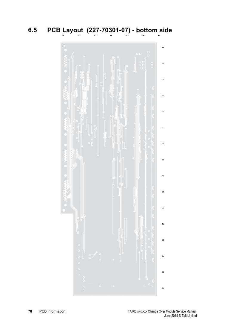
78 PCB information TA703-xx-xxxx Change Over Module Service Manual June 2014 © Tait Limited
6.5 PCB Layout (227-70301-07) - bottom side
LJ
KG
HF
DE
CB
AM
NP
QR
1234567B
HO
LE
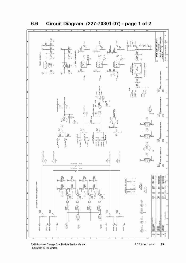
TA703-xx-xxxx Change Over Module Service Manual PCB information 79 June 2014 © Tait Limited
6.6 Circuit Diagram (227-70301-07) - page 1 of 2
0123456789
0123456789
AB
CD
EF
GH
JK
LM
NP
QR
RE
V/IS
SA
ME
ND
ME
NT
SD
AT
EA
PV
DD
.O.
CH
KD
DR
AW
NN
O.S
HE
ET
S:
FIL
EN
AM
E:
TA
ITE
LE
CT
RO
NIC
S
IPN
:
FIL
ED
AT
E:
ISS
UE
:ID
:.
2.S
C.
PR
OJE
CT:
DE
SIG
NE
R:
1
4
TA
703-0
1T
800
CH
AN
GE
-OV
ER
MO
DU
LE
a070317b
227-7
0301-0
7
14-J
ul-
05
B
TA
703-0
1H
.OV
ER
TO
OM
P1
PR
OT
OT
YP
EM
.HA
LL
H.O
.M
.HA
LL
S.C
RA
GG
17/0
5/9
6
1A
PC
BU
PD
AT
EM
.HA
LL
H.O
.M
.HA
LL
S.C
RA
GG
07/0
6/9
6
2A
CH
AN
GE
NO
TE
TA
703-0
1:1
2/9
6:0
001
M.H
AL
LH
.O.
M.H
AL
LS
.CR
AG
G17/1
2/9
6
3A
MIG
RA
TE
DT
OU
NIC
AD
M.H
AL
LH
.O.
M.H
AL
LS
.CR
AG
G20/0
3/9
7
4A
EC
O770176.
TM
BH
.O.
M.H
AL
LJA
CK
SO
N09/0
9/9
9
5A
EC
O770212.
M.H
AL
L
6A
EC
O770128
MA
JO
RC
HA
NG
ES
AD
AM
.DH
.OM
.HA
LL
JA
CK
SO
N06/0
4/0
0
06B
EC
O720611
TB
H.O
.M
.HA
LL
07A
EC
O101400260
M.H
AL
LH
.O.
M.H
AL
LC
.LE
WIS
04F
EB
05
07B
EC
O101400323
-D
11
0R
OTA
TE
M.H
AL
LH
.O.
M.H
AL
LC
.LE
WIS
14JU
L05
PL
315
WA
YR
-AN
GL
ED
RA
NG
EP
LU
GP
L1
15
WA
YR
-AN
GL
ED
RA
NG
EP
LU
GP
L2
15
WA
YR
-AN
GL
ED
RA
NG
EP
LU
GS
K1
25
WA
YR
-AN
GL
ED
RA
NG
ES
OC
KE
T
R135
47K
R137
47K
R138
47K
R136
47K
R140
47K
R141
47K
R127
100K
R128
100K
C122
10N
C123
10N
*IC
11
2P
P101205
VIN
+4
VIN
-1
VO
UT
+3
VO
UT-
2
P106
I/O
PA
D
P105
I/O
PA
D
*C161
100U
*C162
1U
0*C
165
1U
0*C
164
100U
*C163
470U
*C160
220U
FID
AF
IDU
CIA
LF
IDB
FID
UC
IAL
IC101
4001B
T V-
7
V+
14
IC101
4001B
T12
13
11
IC101
4001B
T8 9
10
IC101
4001B
T5 6
4
IC101
4001B
T1 2
3
IC100
4001B
T V-
7
V+
14
D SG
Q102
ZV
N3306A
D SG
Q103
ZV
N3306A
D107
MR
A4004 P103
I/O
PA
D
P102
I/O
PA
D
C126
100P
SW
100
8B
AN
KD
IPS
W
6
11
SW1008BANKDIPSW
2
15
SW1008BANKDIPSW
1
16
R120
100K
R121
100K
C120
10N
C121
10N
IC100
4001B
T1 2
3
IC100
4001B
T5 6
4
IC100
4001B
T12
13
11
D SG
Q100
ZV
N3306A
D SG
Q101
ZV
N3306A
R139
100K
C128
1N
0
C127
1N
0
IC102
TL
C2272
V-
4
V+
8+ -IC
102
TL
C2272
5 6
7
+ -IC102
TL
C2272
3 2
1
C100
100N
C101
100N
C102
100N
SW
100
8B
AN
KD
IPS
W
3
14
SW
100
8B
AN
KD
IPS
W
413
SW
100
8B
AN
KD
IPS
W
512
TS
LO
TS
LO
TT
HO
LE
HO
LE
LV
I
IC109
MC
34064D IN
2
GN
D
4
RE
S1
LV
I
IC110
MC
34064D IN
2
GN
D
4
RE
S1
CW
RV
100
10K
15T
13
2 CW
RV
101
10K
15T
13
2
R147
3K
9
R153
3K
9
R146
10K
R152
10K
D109
MR
A4004
D112
MR
A4004
C11
01N
0
C11
41N
0
GR
OU
ND
VIN
VO
UT
IC106
78L
05
8
23
67
1
GR
OU
ND
VIN
VO
UT
IC105
78L
08
8
23
67
1
C106
100U
C106A
10U
C106B
100N
R106
2K
2
C105
100U
C105A
10U
C105B
100N
R105
4K
7
R142
10K
R143
10K
C131
10U
D101
MR
A4004
D100
MR
A4004
D102
MR
A4004
D103
MR
A4004
D108
MR
A4004
R149
47K
R148
100K
D SG
Q107
ZV
N3306A
Q106
BC
857
P101
I/O
PA
D
RL
100
TQ
2L
22 4
3
RL
100
TQ
2L
29 7
8
RL
101
TQ
2L
22 4
3
RL
101
TQ
2L
29 7
8
RL
103
TQ
2L
2
9 7
8
RL
103
TQ
2L
22 4
3
RL
102
TQ
2L
29 7
8
RL
102
TQ
2L
22 4
3
-+
SE
T
RL
100
TQ
2L
26
10
-+
SE
T
RL
102
TQ
2L
26
10
-+
SE
T
RL
101
TQ
2L
26
10
-+
SE
T
RL
103
TQ
2L
26
10
-+R
L100
TQ
2L
251
-+R
L102
TQ
2L
251
-+R
L103
TQ
2L
251
-+R
L101
TQ
2L
251
LV
I
IC111
MC
34064D IN
2
GN
D
4
RE
S1
CW
RV
102
10K
15T
13
2
R159
3K
9
R157
10K
C11
81N
0
D11
5R
ED
21
R158
470
P100
I/O
PA
D P108
I/O
PA
DP
107
I/O
PA
D
D11
0M
RA
4004
SK
1+
5V
-OU
T12
SK
1+
5V
-OU
T13
SK
1+
5V
-OU
T24
SK
1+
5V
-OU
T25
SK
11
SK
17
SK
19
SK
1
10
+13V
8
PL
1R
XA
UD
A+
1 PL
1R
XA
UD
A-
2PL
2R
XA
UD
B+
1 PL
2R
XA
UD
B-
2 PL
1T
XA
UD
A+
3 PL
1T
XA
UD
A-
4PL
2T
XA
UD
B+
3 PL
2T
XA
UD
B-
4
PL
3R
EM
OT
ER
XL
INE
+1
PL
3R
EM
OT
ER
XL
INE
-2
SK
1
14
SK
1
15
SK
1
16
SK
1
17
PL
3R
EM
OT
ET
XL
INE
-4
PL
3R
EM
OT
ET
XL
INE
+3
+5V
+5V
+5V
+5V
+5V
+5V
+5V
+5V
+13V
8
PL
1T
X_K
EY
_A
7 PL
2T
X_K
EY
_B
7
PL
3R
EM
OT
ET
XK
EY
7
SK
1
19
PL
1R
X_G
AT
E_A
5 PL
2R
X_G
AT
E_B
5
PL
3R
XG
AT
EO
/P5
SK
1
18
RS
SI-
B3A
5
RS
SI-
A3A
7
SK
1R
SS
I_O
/P21
PL
3R
SS
IA
CT
IVE
11
DIR
_P
C0
2L
4
DIR
_P
C2
2L
5
CN
TR
L_P
C1
2L
4
+5V
+5V
+8V
PL
1P
SU
-A13
PL
2P
SU
-B13
+5V
+5V
+13V
8
+13V
8
+13V
8+
5V
+13V
8+
8V
+8V
+8V
+13V
8
RX
_G
AT
E_A
3H
9
RX
_G
AT
E_B
3H
5
TX
_K
EY
_A
3H
7
TX
_K
EY
_B
3H
3
PA
62H
6
PA
22H
5
PL
3V
+B
AT
T8
+5V
BA
TT
_L
OW
2L
5
+5V
PL
2T
X_K
EY
_B
10
PL
1T
X_K
EY
_A
10
+13V
8
PL
3
15
DC
/DC
CO
NV
ER
TE
R
OP
TIO
NA
L+
13V
8
+13V
8
CO
AX
IAL
RE
LA
Y
*N
OT
NO
RM
AL
LY
PL
AC
ED
DC
_P
WR
_C
OM
PA
RA
TO
RS
RX
/TX
C/O
RE
LA
Y
SE
LE
CT
BA
SE
PO
WE
R_R
EG
UL
AT
OR
S
SW
100
3-1
4
6-1
1
X
4-1
3
1-1
6
X
2-1
5
5-1
27-1
0
TT
TT
8-9
BS
BS
BS
TT
ON
OF
FL
OC
AT
ION
1F
0
1K
4
1F
0
1F
61
F6
1F
03
J3
3J7
RE
LA
YC
ON
TA
CT
SD
RA
WN
INR
ES
ET
STA
TE
+ -
+ -
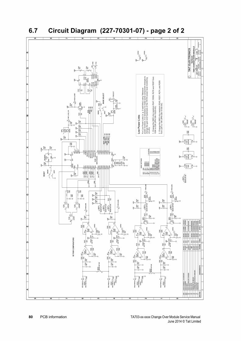
80 PCB information TA703-xx-xxxx Change Over Module Service Manual June 2014 © Tait Limited
6.7 Circuit Diagram (227-70301-07) - page 2 of 2
0123456789
0123456789
AB
CD
EF
GH
JK
LM
NP
QR
RE
V/I
SS
AM
EN
DM
EN
TS
DA
TE
AP
VD
D.O
.C
HK
DD
RA
WN
NO
.SH
EE
TS
:F
ILE
NA
ME
:
TA
ITE
LE
CT
RO
NIC
S
IPN
:
FIL
ED
AT
E:
ISS
UE
:ID
:.
2.S
C.
PR
OJ
EC
T:
DE
SIG
NE
R:
2
4
TA
70
3-0
1T
80
0C
HA
NG
E-O
VE
RM
OD
UL
E
a070317b
227-7
0301-0
7
14-J
ul-
05
B
TA
703-0
1H
.OV
ER
TO
OM
P1
PR
OT
OT
YP
EM
.HA
LL
H.O
.M
.HA
LL
S.C
RA
GG
17/0
5/9
6
1A
PC
BU
PD
AT
EM
.HA
LL
H.O
.M
.HA
LL
S.C
RA
GG
07/0
6/9
6
2A
CH
AN
GE
NO
TE
TA
703-0
1:1
2/9
6:0
001
M.H
AL
LH
.O.
M.H
AL
LS
.CR
AG
G17/1
2/9
6
3A
MIG
RA
TE
DT
OU
NIC
AD
M.H
AL
LH
.O.
M.H
AL
LS
.CR
AG
G20/0
3/9
7
4A
EC
O770176.
TM
BH
.O.
M.H
AL
LJA
CK
SO
N09/0
9/9
9
5A
EC
O770212.
M.H
AL
L
6A
EC
O770128
MA
JO
RC
HA
NG
ES
AD
AM
.DH
.OM
.HA
LL
JA
CK
SO
N06/0
4/0
0
06B
EC
O720611
TB
H.O
.M
.HA
LL
07A
EC
O101400260
M.H
AL
LH
.O.
M.H
AL
LC
.LE
WIS
04F
EB
05
07B
EC
O101400323
-D
110
RO
TA
TE
M.H
AL
LH
.O.
M.H
AL
LC
.LE
WIS
14JU
L05
IC200
68H
C705C
8F
N
IRQ
2
TC
AP
41
PA
75
PA
66
PA
57
PA
48
PA
39
PA
210
PA
111
PA
012
PB
721
PB
620
PB
519
PB
417
PB
316
PB
215
PB
114
PB
013
OS
C1
43
OS
C2
42
GN
D
22
RE
SE
T
1
VP
P
4
VC
C
44
NC
3
NC
18
NC
23
NC
40
PD
739
TC
MP
38
SS
/PD
537
SC
K/P
D4
36
MO
SI/P
D3
35
MIS
O/P
D2
34
TD
O/P
D1
33
RD
I/P
D0
32
PC
724
PC
625
PC
526
PC
427
PC
328
PC
229
PC
130
PC
031
+ -IC202
339D
9 8
14
CW
RV
203
10K
15T
13
2
C229
10U
R249
10K
+ -IC202
339D
7 6
1
CW
RV
205
10K
15T
13
2
C254
10U
R278
10K
+ -IC202
339D
11
10
13
CW
RV
204
10K
15T
13
2
C233
10U
R261
10K
+ -IC202
339D
5 4
2
CW
RV
206
10K
15T
13
2
C258
10U
R289
10K
X200
4.0
32M
C237
22P
C238
22P
LV
I
IC204
MC
34064D IN
2
GN
D
4
RE
S1
R228
10K
R266
10K
R236
10K
C228
4N
7
C253
4N
7
C232
4N
7
C257
4N
7
R248
220K
R277
220K
R260
220K
R288
220K
R224
10K
C200
100N
R250
10K
R251
10K
R252
10K
R233
10K
R234
10K
R235
10K
R237
10K
P200
RE
V-P
WR
-B
I/O
PA
DR
243
47K
P208
FW
D-P
WR
-B
I/O
PA
D
P209
GN
D
I/O
PA
D
R272
47K
P203
RE
V-P
WR
-A
I/O
PA
D
P204
GN
D
I/O
PA
D
P211
FW
D-P
WR
-A
I/O
PA
D
SW
200
SP
DT
3
21
SW
202
SP
DT
1
23
R229
1K
0
R230
1K
5
R264
2M
2
SW
201
8B
AN
KD
IPS
W
5
12 S
W201
8B
AN
KD
IPS
W
89
SW
201
8B
AN
KD
IPS
W
314
SW
201
8B
AN
KD
IPS
W
215
SW
201
8B
AN
KD
IPS
W
116
R269
22K
P220
I/O
PA
D
P221
I/O
PA
D
Q201
BC
817
R279
10K
R290
10K
Q202
BC
817
SW
201
8B
AN
KD
IPS
W
710
SW
201
8B
AN
KD
IPS
W
611
D202
BA
V99
23
D202
BA
V993
1
D205
BA
V99
23
D205
BA
V99
3 1
P202
I/O
PA
D
P210
I/O
PA
D
P205
I/O
PA
D
P213
I/O
PA
D
+ -IC201
LM
324D
12
13
14
+ -IC201
LM
324D
5 6
7
IC201
LM
324D
V-
11
V+
4
R283
47K
R284
47K
R285
100K
R286
100K
R287
22K
R255
47K
R256
47K
R257
22K
R259
22K
R258
100K
+ -IC201
LM
324D
3 2
1R
276
22K
R275
100K
R274
100K
R273
47K
R244
47K
+ -IC201
LM
324D
10 9
8
R245
22K
R247
22K
R246
100K
IC203
74H
C86T
5 46
IC203
74H
C86T
12
13
11
IC203
74H
C86T
1 23
IC203
74H
C86T
9
10
8
C224
1N
0
C249
1N
0
C201
100N
R239
22K
*R238
22K Q200
BC
817
IC202
339D V
-12
V+
3
IC203
74H
C86T
V-
7
V+
14
C203
100N
SW
201
8B
AN
KD
IPS
W
413
C220
100N
C221
100N
R220
100K
R221
100K
IC100
4001B
T
8 91
0
IC207
MA
X232
C1+
1
C1-
3
C2+
4
C2-
5
T2IN
10
T1IN
11
R1O
UT
12
R2O
UT
9
GN
D
15+
V
16
5/1
0V
+2
5/1
0V
-6
T2O
UT
7
T1O
UT
14
R1IN
13
R2IN
8
C246
10U
C245
10U
C243
10U
C244
10U
R213
1K
0
D210
BA
V99
31
D211
BA
V99
31
D210
BA
V99
23
D211
BA
V99
23
R271
27K
R281
27K
R270
10K
R280
10K
+5
V+
5V
PL
2F
WD
-PW
R-B
11
PL
2R
EV
-PW
R-B
12
PL
1R
EV
-PW
R-A
12
PL
1F
WD
-PW
R-A
11
+8
V
+5
V
+8
V
+5
V
+8
V
+5
V
+8
V
+5
V
+1
3V
8+
5V
PA
03L
8
PA
13L
7
PA
33G
7
PA
43L
5
PA
53L
3
MO
SI
4B
8
SC
K4B
8
LE
4B
8
+5
V
+5
V
+5
V
+5
V+
5V
+5
V
+5
V
+5
V+
5V
+5
V
PA
73G
6
PB
73G
4
+5
V
PL
3T
XS
EL
EC
T14
PL
3R
MT
_A
LM
_C
LR
12
+8
V
+5
V
+5
V
PL
1R
EV
-AL
MA
8
PL
2R
EV
AL
MB
8
PL
2F
WD
AL
MB
6
+5
V
PL
1F
WD
-AL
MA
6
+8
V
DIR
_P
C2
1B
4
DIR
_P
C0
1B
5
CN
TR
L_
PC
11B
6
+8
V
PL
3R
SS
IA
LA
RM
13
SK
1
23
+8
V+
5V
PA
61N
5
PA
21N
4
BA
TT
_L
OW
1N
2
SK
1R
XD
3
SK
1T
XD
2
+5
V+
5V
RF
PW
RC
OM
PA
RA
TO
RS
RE
SE
T
BA
SE
SE
LE
CT
SW
20
1S
ET
TIN
GS
SW
1S
W2
ON
ON
OF
FO
FF
OF
FO
FF
MO
DE
AM
OD
EB
1-1
62
-15
3-1
44
-13
NO
TU
SE
D
SW
2S
W1
5-1
2L
INK
RE
VP
WR
A-B
DIS
AB
LE
FW
DA
LM
B6
-11
7-1
0D
ISA
BL
EF
WD
AL
MA
8-9
LIN
KF
WD
PW
RA
-B2
-F0
2F
22
B5
2H
02
F4
2F
52
F5
2-B
2
LO
CA
TIO
NM
OD
EC
NO
TU
SE
D
For
Low
Pow
er
Lin
ks
(e.g.2
watt
links)
usin
gTele
wave
pow
er
monitors
,it
isnecessary
tom
ake
som
ecom
ponentchanges
tochange
the
gain
and
hyste
resis
ofth
eTA
703
pow
er
levelm
onitoring
circuitry
.
1.C
hange
the
0805
chip
resis
tors
R247,R
259,R
276
and
R287
from
100K
to22K
(IP
N036-1
5220-0
0).
2.C
hange
the
0805
chip
resis
tors
R245,R
257,R
274,and
R285
from
22K
to10K
(IP
N036-1
5100-0
0).
Lo
wP
ow
er
Lin
ks
ON
ON
MO
DE
D

TA703-xx-xxxx Change Over Module Service Manual PCB information 81 June 2014 © Tait Limited
6.8 Circuit Diagram (227-70301-07) - page 3 of 4
0123456789
0123456789
AB
CD
EF
GH
JK
LM
RE
V/IS
SA
ME
ND
ME
NT
SD
AT
EA
PV
DD
.O.
CH
KD
DR
AW
NN
O.S
HE
ET
S:
FIL
EN
AM
E:
TA
ITE
LE
CT
RO
NIC
S
IPN
:
FIL
ED
AT
E:
ISS
UE
:ID
:.
2.S
C.
PR
OJ
EC
T:
DE
SIG
NE
R:
3
4
TA
70
3-0
1T
80
0C
HA
NG
E-O
VE
RM
OD
UL
E
a0
70
31
7b
22
7-7
03
01
-07
14
-Ju
l-0
5
B
TA
70
3-0
1H
.OV
ER
TO
OM
P1
PR
OT
OT
YP
EM
.HA
LL
H.O
.M
.HA
LL
S.C
RA
GG
17
/05
/96
1A
PC
BU
PD
AT
EM
.HA
LL
H.O
.M
.HA
LL
S.C
RA
GG
07
/06
/96
2A
CH
AN
GE
NO
TE
TA
70
3-0
1:1
2/9
6:0
00
1M
.HA
LL
H.O
.M
.HA
LL
S.C
RA
GG
17
/12
/96
3A
MIG
RA
TE
DT
OU
NIC
AD
M.H
AL
LH
.O.
M.H
AL
LS
.CR
AG
G2
0/0
3/9
7
4A
EC
O7
70
17
6.
TM
BH
.O.
M.H
AL
LJ
AC
KS
ON
09
/09
/99
5A
EC
O7
70
21
2.
M.H
AL
L
6A
EC
O7
70
12
8M
AJ
OR
CH
AN
GE
SA
DA
M.D
H.O
M.H
AL
LJ
AC
KS
ON
06
/04
/00
06
BE
CO
72
06
11
TB
H.O
.M
.HA
LL
07
AE
CO
10
14
00
26
0M
.HA
LL
H.O
.M
.HA
LL
C.L
EW
IS0
4F
EB
05
07
BE
CO
10
14
00
32
3-
D110
RO
TA
TE
M.H
AL
LH
.O.
M.H
AL
LC
.LE
WIS
14
JU
L0
5
+- IC3
00
LM
32
4D
32
1
+- IC3
00
LM
32
4D
56
7
+ -IC3
01
33
9D
5 4
2
+- IC3
01
33
9D
76
1
IC3
00
LM
32
4D
V-
11
V+
4
R3
22
22
0K
R3
58
22
0K
C3
22
10
0P
C3
33
10
0P
R3
21
22
0K
CW
RV
30
0 5K
13
2
R3
23
47
K
C3
21
47
N
R3
25
4K
7
R3
59
4K
7C
33
24
7N
R3
55
22
0K
CW
RV
30
1 5K
13
2
R3
20
4K
7
R3
54
4K
7
R3
56
47
K
R3
63
1K
0
Q3
03
BC
81
7Q
30
2B
C8
17
R3
64
1K
0
R3
32
1K
0
R3
31
1K
0R
33
01
2K
Q3
00
BC
85
7Q
30
1B
C8
57
R3
65
1K
0
R3
66
18
0K
R3
33
1K
0
R3
34
18
0K
R3
29
1K
0R
32
81
K0
R3
35
3K
3
+ -IC3
01
33
9D
11
10
13
+ -IC3
01
33
9D
9 8
14
R3
41
22
K
R3
42
10
K
Q3
07
BC
85
7
D3
06
GR
EE
N21
R3
43
4K
7R
34
41
K5
R3
47
47
K
R3
48
47
K
Q3
08
BC
85
7
D3
08
GR
EE
N21
R3
49
4K
7R
35
01
K5
R3
78
22
K
R3
79
10
K
Q3
09
BC
85
7
D3
12
GR
EE
N21
R3
80
4K
7R
38
11
K5
R3
84
47
K
R3
85
47
K
Q3
10
BC
85
7
D3
14
GR
EE
N21
R3
86
4K
7R
38
71
K5
D3
05
BA
V9
923 D
30
7
BA
V9
923 D
311
BA
V9
923 D
31
3
BA
V9
923
+ -IC3
00
LM
32
4D
12
13
14
+ -IC3
00
LM
32
4D
10 9
8
R3
36
3K
3R
33
73
K3
R3
24
10
0K
R3
57
10
0K
R3
67
18
0K
R3
68
1K
0
R3
74
18
0K
R3
73
1K
0
R3
71
1K
5
R3
72
5K
6C
33
51
U0
D3
05
BA
V9
93 1
D3
07
BA
V9
93 1
D3
11
BA
V9
93 1
D3
13
BA
V9
93 1
IC3
01
33
9D V-
12
V+
3
D3
00
GR
N12
D3
01
GR
N12
D3
02
GR
N12
TP
30
0I/O
PA
D
TP
30
5I/O
PA
D
TP
30
1
I/O
PA
D
TP
30
2
I/O
PA
D
C3
20
1N
0
C3
31
1N
0
C3
28
1N
0
C3
38
1N
0
C3
39
1N
0
C3
27
1N
0
SW
10
0
8B
AN
KD
IPS
W
89
SW
10
0
8B
AN
KD
IPS
W
71
0
TP310
I/OPAD
TP311
I/OPAD
+8V
+8V
PL
1R
SS
I-A
14
PL
2R
SS
I-B
14
PA
32
H6
+8V
+8V
+5V
+8V
PA
02
H5
PA
12
H5
PA
42
H6
PA
52
H6
PL
1G
ND
15
PL
2G
ND
15
+5V
+5V
+5V
+5V
+5V
+5V
+5V
+5V
+5V
PA
72
H6
+5V
PB
72
H5
+8V
+8V
RS
SI-
B
1H
6
RS
SI-
A
1H
7
RX
_G
AT
E_B
1H
5
TX
_K
EY
_A
1H
4
RX
_G
AT
E_A
1H
6 TX
_K
EY
_B
1H
3
RS
SI
CO
MP
AR
AT
OR
S
RSSI-A<RSSI-BLED1
RS_A>RS-BLED2
RSAORRS-B>80db
RS
I-A
RS
I-B
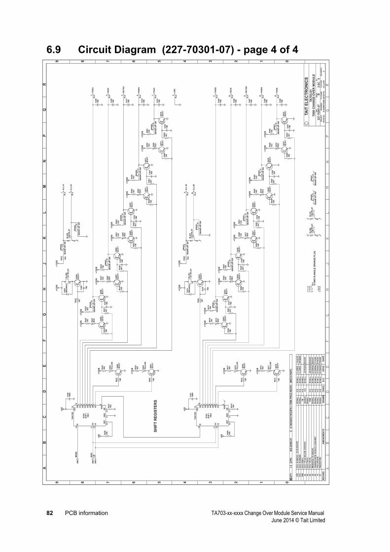
82 PCB information TA703-xx-xxxx Change Over Module Service Manual June 2014 © Tait Limited
6.9 Circuit Diagram (227-70301-07) - page 4 of 4
0123456789
0123456789
AB
CD
EF
GH
JK
LM
NP
QR
RE
V/I
SS
AM
EN
DM
EN
TS
DA
TE
AP
VD
D.O
.C
HK
DD
RA
WN
NO
.SH
EE
TS
:F
ILE
NA
ME
:
TA
ITE
LE
CT
RO
NIC
S
IPN
:
FIL
ED
AT
E:
ISS
UE
:ID
:.
2.S
C.
PR
OJ
EC
T:
DE
SIG
NE
R:
4
4
TA
70
3-0
1T
80
0C
HA
NG
E-O
VE
RM
OD
UL
E
a070317b
227-7
0301-0
7
14-J
ul-
05
B
TA
703-0
1H
.OV
ER
TO
OM
QT
Y:
IPN
:1
.00
02
-20
06
8-0
7IC
MC
68
HC
70
5C
8F
N1
-TIM
EP
RO
GM
ICR
O(M
EC
HP
AR
T)
P1
PR
OT
OT
YP
EM
.HA
LL
H.O
.M
.HA
LL
S.C
RA
GG
17/0
5/9
6
1A
PC
BU
PD
AT
EM
.HA
LL
H.O
.M
.HA
LL
S.C
RA
GG
07/0
6/9
6
2A
CH
AN
GE
NO
TE
TA
703-0
1:1
2/9
6:0
001
M.H
AL
LH
.O.
M.H
AL
LS
.CR
AG
G17/1
2/9
6
3A
MIG
RA
TE
DT
OU
NIC
AD
M.H
AL
LH
.O.
M.H
AL
LS
.CR
AG
G20/0
3/9
7
4A
EC
O770176.
TM
BH
.O.
M.H
AL
LJA
CK
SO
N09/0
9/9
9
5A
EC
O770212.
M.H
AL
L
6A
EC
O770128
MA
JO
RU
PD
AT
ES
AD
AM
.DH
.OM
.HA
LL
JA
CK
SO
N06/0
4/0
0
06B
EC
O720611
TB
H.O
.M
.HA
LL
07A
EC
O101400260
M.H
AL
LH
.O.
M.H
AL
LC
.LE
WIS
04F
EB
05
07B
EC
O101400323
-D
110
RO
TA
TE
M.H
AL
LH
.O.
M.H
AL
LC
.LE
WIS
14JU
L05
SH
IFT
RE
G
IC400
74H
C595
DI
14
CK
11
LE
12
RS
T
10
GN
D
8
OE
13V
CC1
6 Q0
15
Q1
1
Q2
2
Q3
3
Q4
4
Q5
5
Q6
6
Q7
7
SQ
H9
SH
IFT
RE
G
IC401
74H
C595
DI
14
CK
11
LE
12
RS
T
10
GN
D
8
OE
13V
CC1
6 Q0
15
Q1
1
Q2
2
Q3
3
Q4
4
Q5
5
Q6
6
Q7
7
SQ
H9
R421
1K
0
R470
1K
0
R420
1K
0
R469
1K
0
R432
4K
7
Q404
BC
817
D400
MR
A4004
RL
400
12V
RE
LA
Y101
RL
400
12V
RE
LA
Y
243
R433
1K
0
R431
4K
7R
430
10K
Q406
BC
817
Q405
BC
817
D401
RE
D21
R428
1K
5R
429
1K
0
R450
4K
7R
439
10K
Q408
BC
817
Q407
BC
817
D402
RE
D21
R437
1K
5R
438
1K
0
R454
4K
7R
453
10K
Q410
BC
817
Q409
BC
817
D403
RE
D21
R451
1K
5R
452
1K
0
R461
4K
7R
460
10K
Q412
BC
817
Q411
BC
817
D404
RE
D21
R458
1K
5R
459
1K
0
R465
4K
7R
464
10K
Q414
BC
817
Q413
BC
817
D405
RE
D21
R462
1K
5R
463
1K
0
R423
10K
Q400
BC
817
D408
YE
LL
OW
21
R422
1K
5
R425
10K
Q401
BC
817
D409
YE
LL
OW
21
R424
1K
5
R482
4K
7
Q422
BC
817
D414
MR
A4004
RL
401
12V
RE
LA
Y101
RL
401
12V
RE
LA
Y
243
R483
1K
0
R481
4K
7R
480
10K
Q424
BC
817
Q423
BC
817
D415
RE
D21
R478
1K
5
R479
1K
0
R487
4K
7R
486
10K
Q426
BC
817
Q425
BC
817
D416
RE
D21
R484
1K
5R
485
1K
0
R493
4K
7R
492
10K
Q428
BC
817
Q427
BC
817
D417
RE
D21
R490
1K
5R
491
1K
0
R497
4K
7R
496
10K
Q430
BC
817
Q429
BC
817
D418
RE
D21
R494
1K
5R
495
1K
0
R501
4K
7R
500
10K
Q432
BC
817
Q431
BC
817
D419
RE
D21
R498
1K
5R
499
1K
0
R472
10K
Q418
BC
817
D410
YE
LL
OW
21
R471
1K
5
R474
10K
Q419
BC
817
D411
YE
LL
OW
21
R473
1K
5
C400
100N
C401
100N
PL
41
5W
AY
R-A
NG
LE
DR
AN
GE
PL
UG
SW
400
8B
AN
KD
IPS
W
11
6
SW
400
8B
AN
KD
IPS
W
21
5
SW
400
8B
AN
KD
IPS
W
31
4
SW
400
8B
AN
KD
IPS
W
41
3
SW
400
8B
AN
KD
IPS
W
51
2
SW
400
8B
AN
KD
IPS
W
89
SW
400
8B
AN
KD
IPS
W
611
SW
400
8B
AN
KD
IPS
W
71
0
SW
401
8B
AN
KD
IPS
W
21
5
SW
401
8B
AN
KD
IPS
W
11
6
SW
401
8B
AN
KD
IPS
W
31
4
SW
401
8B
AN
KD
IPS
W
41
3
SW
401
8B
AN
KD
IPS
W
512
SW
401
8B
AN
KD
IPS
W
89
SW
401
8B
AN
KD
IPS
W
71
0
SW
401
8B
AN
KD
IPS
W
611
RL
400
12V
RE
LA
Y
978
RL
401
12V
RE
LA
Y
978
C441
1N
0
C449
1N
0
C448
1N
0
C440
1N
0
C439
1N
0
C447
1N
0
C438
1N
0
C446
1N
0
C437
1N
0
C445
1N
0
C436
1N
0
C421
1N
0
C422
1N
0
C423
1N
0
C424
1N
0
C425
1N
0
C433
1N
0
C432
1N
0
C431
1N
0
C430
1N
0
C429
1N
0
C420
1N
0
MO
SI
2M
6
SC
K2M
6L
E2M
5
+5
V
+5
V
+5
V
+5
V
+1
3V
8+
13
V8
PL
4A
LL
1A
1
PL
4A
LL
2A
2
+1
3V
8+
13
V8
PL
4F
WD
A3
+1
3V
8+
13
V8
+1
3V
8+
13
V8
+1
3V
8+
13
V8
+1
3V
8+
13
V8
PL
4R
EV
A4
PL
4M
UT
EA
5
PL
4R
SS
IA6
PL
4P
SU
A7
+1
3V
8
+1
3V
8
+1
3V
8+
13
V8
PL
4A
LL
1B
9
PL
4A
LL
2B
10
+1
3V
8+
13
V8
PL
4F
WD
B11
+1
3V
8+
13
V8
+1
3V
8+
13
V8
+1
3V
8+
13
V8
+1
3V
8+
13
V8
PL
4R
EV
B12
PL
4M
UT
EB
13
PL
4R
SS
IB14
PL
4P
SU
B15
+1
3V
8
+1
3V
8
PL
4G
ND
8
SH
IFT
RE
GIS
TE
RS
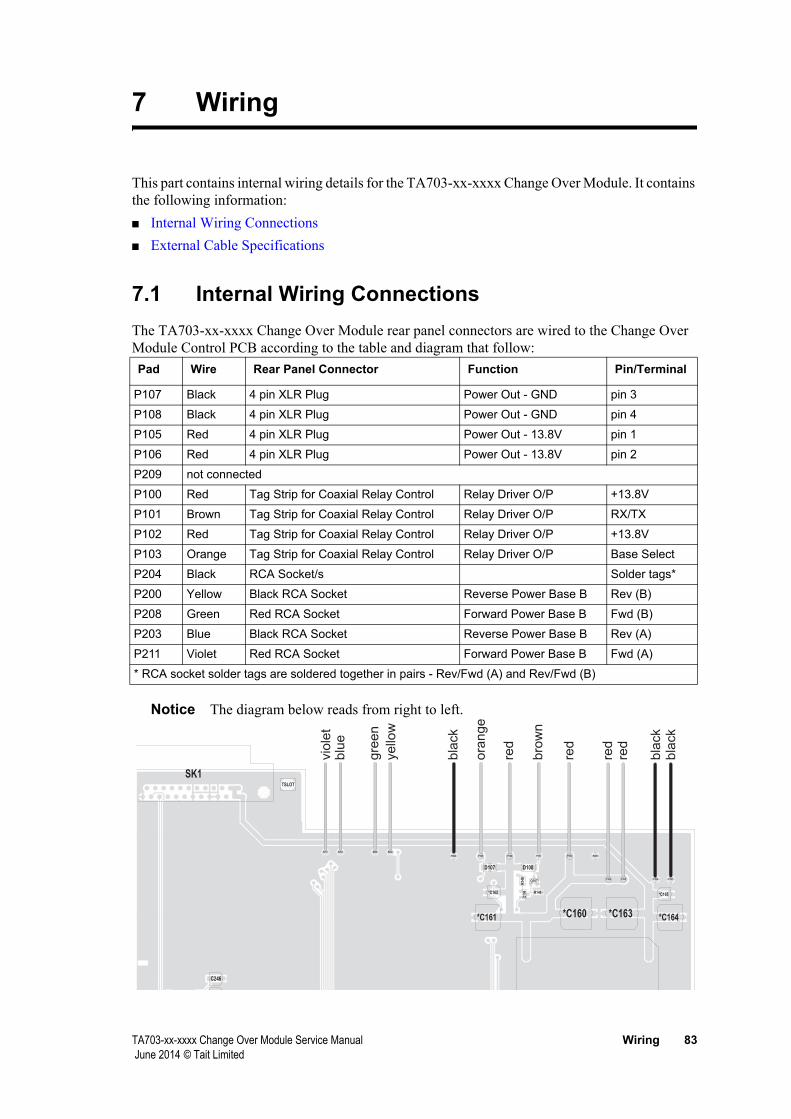
TA703-xx-xxxx Change Over Module Service Manual Wiring 83 June 2014 © Tait Limited
7 Wiring
This part contains internal wiring details for the TA703-xx-xxxx Change Over Module. It contains the following information:■ Internal Wiring Connections■ External Cable Specifications
7.1 Internal Wiring ConnectionsThe TA703-xx-xxxx Change Over Module rear panel connectors are wired to the Change Over Module Control PCB according to the table and diagram that follow:
P107 Black 4 pin XLR Plug Power Out - GND pin 3
P108 Black 4 pin XLR Plug Power Out - GND pin 4
P105 Red 4 pin XLR Plug Power Out - 13.8V pin 1
P106 Red 4 pin XLR Plug Power Out - 13.8V pin 2
P209 not connected
P100 Red Tag Strip for Coaxial Relay Control Relay Driver O/P +13.8V
P101 Brown Tag Strip for Coaxial Relay Control Relay Driver O/P RX/TX
P102 Red Tag Strip for Coaxial Relay Control Relay Driver O/P +13.8V
P103 Orange Tag Strip for Coaxial Relay Control Relay Driver O/P Base Select
P204 Black RCA Socket/s Solder tags*
P200 Yellow Black RCA Socket Reverse Power Base B Rev (B)
P208 Green Red RCA Socket Forward Power Base B Fwd (B)
P203 Blue Black RCA Socket Reverse Power Base B Rev (A)
P211 Violet Red RCA Socket Forward Power Base B Fwd (A)
* RCA socket solder tags are soldered together in pairs - Rev/Fwd (A) and Rev/Fwd (B)
Notice The diagram below reads from right to left.
Pad Wire Rear Panel Connector Function Pin/Terminal
*C160*C161
*C162
*C163 *C164
*C165
C246
D107 D108
P100P101P102P103
P105P106 P107P108
P200P203
P204
P208
P209
P211
Q10
6
Q107
R14
8
R149
SK1TSLOT
vio
let
blu
e
gre
en
ye
llow
bla
ck
ora
ng
e
bro
wn
red
red
red
red
bla
ck
bla
ck
84 Wiring TA703-xx-xxxx Change Over Module Service Manual June 2014 © Tait Limited
7.2 External Cable SpecificationsThis section provides details of the external cables required to instal the TA703-01-000X Change Over Module and the Power Monitor. The cables are supplied as follows:■ Installation Kit/Power Monitor Kit Cable IPN 219-02701-00
■ N-type to N-type cable■ 6 provided - all installation kits■ 1 provided - all power monitor kits
■ Installation Kit Cable (TA703-11-0010) IPN 219-02702-01■ 15-way D-range to 25-way D-range cable
■ Installation Kit Cable (TA703-11-0011) IPN 219-02703-01■ 15-way D-range to 25-way D-range cable■ 2 provided - installation kit TA703-12-0011 only
■ Installation Kit Cable (TA703-11-0012) IPN 219-02700-01■ 15-way D-range to 25-way D-range cable■ 2 provided - installation kit TA703-12-0012 only
■ Installation Kit Cable (TA703-11-7010) IPN 219-03115-00■ 15-way D-range to 25-way D-range cable
■ Installation Kit Cable (TA703-11-8010) IPN 219-03460-00■ 15-way D-range to 25-way D-range cable
■ Power Monitor Kit Cable IPN 219-00025-82■ Phono to phono red/black (or white) twin cable■ 2 provided - all power monitor kits

TA703-xx-xxxx Change Over Module Service Manual Wiring 85 June 2014 © Tait Limited
7.2.1 Installation Kit/Power Monitor Cable IPN 219-02701-00
Six of these cables are supplied in each TA703-01-XXXX Change Over Module Installation Kit.
One cable is also provided in each Power Monitor kit for connecting the Power Monitor to the Duplexer.
1
2
1
525
± 10
mm
Parts List
1 Plug Coax N-type Cord Captive 2 Tait 206-00010-15
2 Cable Coax 50E RG223/U2 Scrn 525mm Tait 240-00010-06
Item Description Quantity Supplier Supplier Part
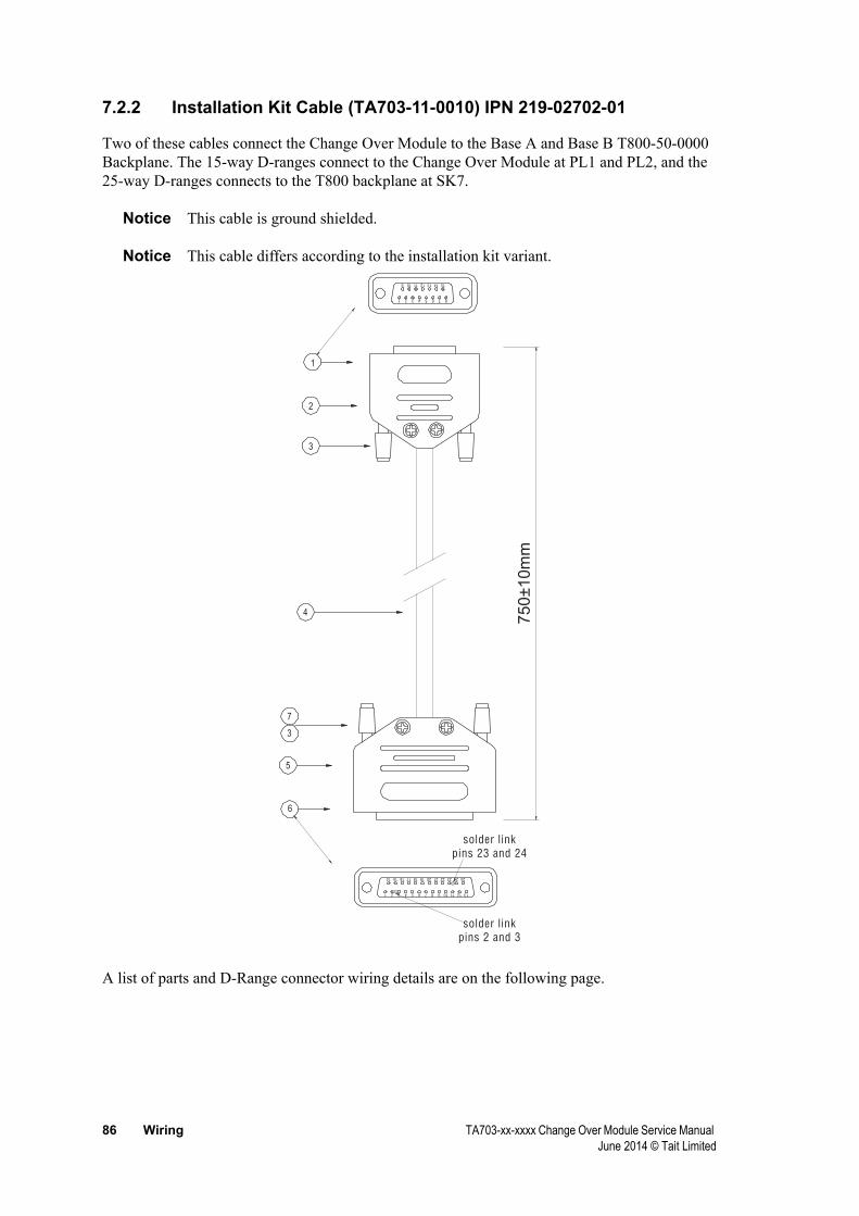
86 Wiring TA703-xx-xxxx Change Over Module Service Manual June 2014 © Tait Limited
7.2.2 Installation Kit Cable (TA703-11-0010) IPN 219-02702-01
Two of these cables connect the Change Over Module to the Base A and Base B T800-50-0000 Backplane. The 15-way D-ranges connect to the Change Over Module at PL1 and PL2, and the 25-way D-ranges connects to the T800 backplane at SK7.
Notice This cable is ground shielded.
Notice This cable differs according to the installation kit variant.
A list of parts and D-Range connector wiring details are on the following page.
3
3
7
4
2
5
1
6
750±1
0m
m
9 11
17
12
18
13
15
10
14
9
19
14
16
11
20
15
21 2422 2523
10 12 133
3
1
1
4
4
2
2
5
5
6
6
7
7
8
8
solder link
pins 2 and 3
solder link
pins 23 and 24

TA703-xx-xxxx Change Over Module Service Manual Wiring 87 June 2014 © Tait Limited
Parts List
1 15-way D-Range Skt S/B 1 Tait 240-02010-54
2 15-way D-Range Cover and Hood 1 Tait 240-06010-18
3 Heatshrink 10mm 60mm Tait 400-00020-70
4 Cable 20 Core Screened 750mm Tait 205-00010-58
5 25-way D-Range Plug S/B 1 Tait 240-06010-63
6 25-way D-Range Cover and Hood 1 Tait 240-00010-17
7 Wire 7/0.2 PVC Grey 80mm Tait 201-00030-08
D-range Wiring - 219-02702-01
The following table describes the wiring of the 15-way and 25-way D-Range connectors on this cable.
1 Rx Line 1 Brown 1
2 Rx Line 4 White 4
3 Tx Line 1 Red 25
4 Tx Line 4 Black 22
5 Rx Gate Orange 14
6 Forward Power Alarm Green/red 10
7 Tx Key Yellow 17
8 Reverse Power Alarm Red/blue 11
9 Rx Mute Pink 14
10 Tx Enable Blue 17
11 not connected - -
12 not connected - -
13 13.8V+ Violet 2, 3
14 Green 5
15 0V- Grey 23, 24
All remaining 25-way D-Range pins are not connected.
Notice On the 25-way D-range, pins 2 and 3, and pins 23 and 24 are solder linked. This is done to provide power and Ground from SK7 on the back plane to the TA703. 13.8V is linked in via pin 2 and pin 3 of SK7. This set up requires removal of +13.8V from the receiver line transformer.
In similar fashion Gnd is provided via linking into the Tx audio centre lines normally present at pins 23 and 24 of SK.
Links on the T800-50-0000 need to be set as follows:■ Lnk9 2-3■ Lnk10 2-3
Item Description Quantity Supplier Supplier Part
15-way pin function wire colour 25-way pin

88 Wiring TA703-xx-xxxx Change Over Module Service Manual June 2014 © Tait Limited
■ Lnk11 2-3■ Lnk12 2-3
Links 1, 2, 3, 4 and 5 on the T800-50-0000 are to be set as preferred by the customer, but are typically left open as they are used for talk-through mode and DC keying. Refer to the T800-50-0000 Service Manual for detailed setup.

TA703-xx-xxxx Change Over Module Service Manual Wiring 89 June 2014 © Tait Limited
7.2.3 Installation Kit Cable (TA703-11-0011) IPN 219-02703-01
Two of these cables connect the Change Over Module to the T800-50-0001 Backplane. The 15-way D-Range connects to the Change Over Module and the 25-way D-range connects to the backplane at SK7.
Notice This cable is ground shielded.
Notice This cable differs according to the installation kit variant.
A list of parts and D-Range connector wiring details are on the following page.
3
3
7
4
2
5
1
6
750±10m
m
9 11
17
12
18
13
15
10
14
9
19
14
16
11
20
15
21 2422 2523
10 12 133
3
1
1
4
4
2
2
5
5
6
6
7
7
8
8
Solder link pins 14 and 15

90 Wiring TA703-xx-xxxx Change Over Module Service Manual June 2014 © Tait Limited
Cable Parts List
1 15-way D-Range Skt S/B 1 Tait 240-02010-54
2 15-way D-Range Cover and Hood 1 Tait 240-06010-18
3 Heatshrink 10mm 60mm Tait 400-00020-70
4 Cable 20 Core Screened 750mm Tait 205-00010-58
5 25-way D-Range Skt S/B 1 Tait 240-06010-67
6 25-way D-Range Cover and Hood 1 Tait 240-06010-17
7 Wire 7/0.2 PVC Black 80mm Tait 201-00030-10
D-range Wiring - 219-02703-01
The following table describes the wiring of the 15-way and 25-way D-Range connectors on this cable.
1 Rx Line 1 Brown 1
2 Rx Line 4 Yellow 4
3 Tx Line 1 Green 5
4 Tx Line 4 Blue 8
5 Rx Gate Violet 14
6 Forward Power Alarm Green/red 22
7 Tx Key Orange 15
8 Reverse Power Alarm Red/blue 12
9 Rx Mute Pink 14
10 Tx Enable Grey 15
11 not connected - -
12 not connected - -
13 13.8V+ Red 25
14 White 9
15 0V- Black 13
All remaining 25-way D-Range pins are not connected.
Notice On the 25-way D-range, pins 14 and 15 each have two wires connected.
Item Description Quantity Supplier Supplier Part
15-way pin function wire colour 25-way pin
TA703-xx-xxxx Change Over Module Service Manual Wiring 91 June 2014 © Tait Limited
7.2.4 Installation Kit Cable (TA703-11-0012) IPN 219-02700-01
This cable connects the Change Over Module to the T800-52-0000 Quasi-Sync Backplane. The 15-way D-range connects to the Change Over Module and the 25-way D-range connects to the T800 backplane at SK7.
Notice This cable is ground shielded.
Notice This cable differs according to the installation kit variant.
A list of parts and D-Range connector wiring details are on the following page.
3
3
7
4
2
5
1
6
75
0±10m
m
9 11
17
12
18
13
15
10
14
9
19
14
16
11
20
15
21 2422 2523
10 12 133
3
1
1
4
4
2
2
5
5
6
6
7
7
8
8

92 Wiring TA703-xx-xxxx Change Over Module Service Manual June 2014 © Tait Limited
Parts List
1 15-way D Range Skt S/B 1 Tait 240-02010-54
2 15-way D Range Cover and Hood 1 Tait 240-06010-18
3 Heatshrink 10mm 60mm Tait 400-00020-70
4 Cable 20 Core Screened 750mm Tait 205-00010-58
5 25-way D Range Skt S/B 1 Tait 240-06010-67
6 25-way D Range Cover and Hood 1 Tait 240-00010-17
7 Wire 7/0.2 PVC Black 80mm Tait 201-00030-10
D-range Wiring - 219-02700-01
The following table describes the wiring of the 15-way and 25-way D-Range connectors on this cable.
1 Rx Line 1 Brown 1
2 Rx Line 4 Yellow 2
3 Tx Line 1 Green 15
4 Tx Line 4 Blue 16
5 Rx Gate Violet 14
6 Forward Power Alarm Green/red 19
7 Tx Key Orange 3
8 Reverse Power Alarm Red/blue 20
9 Rx Mute Pink 14
10 Tx Enable Grey 3
11 not connected - -
12 not connected - -
13 13.8V+ Red 25
14 White 11
15 0V- Black 13
All remaining 25-way D-Range pins are not connected.
On the 25-way D-range, pins 3 and 14 each have two wires connected.
Item Description Quantity Supplier Supplier Part
15-way pin function wire colour 25-way pin
TA703-xx-xxxx Change Over Module Service Manual Wiring 93 June 2014 © Tait Limited
7.2.5 Installation Kit Cable (TA703-11-7010) IPN 219-03115-00
This cable connects the Change Over Module to a TB7100 base station. The 15-way D-range connects to the Change Over Module and the 25-way D-range connects to back of the TB7100
The cable length is 900mm.
Parts List
1 SKT 15wy drng 125° pnl mtg 1 Tait 240-02010-54
2 CONN 15wy hood cvr drng MDJ15 1 Tait 240-06010-18
3 SLVG Si rbr 1.5mm 0.05m Tait 400-00020-05
4 CBL 6 Pair mult shld Data 0.9m Tait 206-00010-25
5 PLG 25wy drng sldr cup RoHS 1 Tait 240-00053-00
6 CONN 25wy hood cvr drng 1 Tait 240-06010-17
D-range Wiring - 219-03115-00
The following table describes the wiring of the 15-way and 25-way D-range connectors on this cable
1 Rx Audio + Brown 1
2 Rx Audio - Red 4
3 Tx Audio + Orange 5
4 Tx Audio - Yellow 8
5 Rx Gate Green 14
6 --
7 Tx Key Violet 15
8 --
9 --
10 --
11 --
12 --
13 +13.8V Blue 25
14 Grey 9
15 Ground Black/braid 13
pin 2 (linked to pin 10)
All remaining 25-way D-range pins are not connected
Item Description Quantity Supplier Supplier part
15-way pin function Wire colour 25-way pin

94 Wiring TA703-xx-xxxx Change Over Module Service Manual June 2014 © Tait Limited
7.2.6 Installation Kit Cable (TA703-11-8010) IPN 219-03460-00
This cable connects the Change Over Module to a TB8100 base station. The 15-way D-range connects to the Change Over Module and the 25-way D-range connects to back of the TB8100
Note that the cable length is 900mm.
Parts List
1 SKT 15wy drng 125° pnl mtg 1 Tait 240-02010-54
2 CONN 15wy hood cvr drng MDJ15 1 Tait 240-06010-18
3 SLVG Si rbr 1.5mm 0.05m Tait 400-00020-05
4 CBL 6 Pair mult shld Data 0.9m Tait 206-00010-25
5 PLG 25wy drng sldr cup RoHS 1 Tait 240-00053-00
6 CONN 25wy hood cvr drng 1 Tait 240-06010-17
D-range Wiring - 219-03460-00
The following table describes the wiring of the 15-way and 25-way D-range connectors on this cable
1 Rx Audio + Black 1
2 Rx Audio - Brown 2
3 Tx Audio + Red 6
4 Tx Audio - Orange 7
5 Rx Gate Green 9
6 Low Forward Power Violet 11
7 Tx Key Dark Blue pin 10 (linked to pin 23)
8 High Reverse Power White 12
9 --
10 --
11 --
12 --
13 +13.8V Grey 13
14 Yellow 8
15 Ground Pink/braid 4
All remaining 25-way D-range pins are not connected
Item Description Quantity Supplier Supplier part
15-way pin function Wire colour 25-way pin
TA703-xx-xxxx Change Over Module Service Manual Wiring 95 June 2014 © Tait Limited
7.2.7 Power Monitor Kit Cable IPN 219-00025-82
This cable connects the power monitor to the forward and reverse power outlets of the Change Over Module. One cable connects the power monitor to Base A, the other to Base B. The black (or white) connectors indicate forward power, the red connectors indicate reverse power.
1500m
m
Parts List
1 Cable twin phono/phono red/black (or white) 1 SI Components CA1042
Item Description Qty Supplier Supplier Part

96 Wiring TA703-xx-xxxx Change Over Module Service Manual June 2014 © Tait Limited