Embed Size (px)
Citation preview

Part No: 90031300 Rev C
Digi International Inc.
AccelePortT1 Modem Bank
Installation and Configuration Guide

The Digi logo is a registered trademark of Digi International Inc.
AccelePort™, T1 Modem Bank™ and EPC/X™ are trademarks of Digi International Inc. All other brand and productnames are the trademarks of their respective holders.
© Digi International Inc. 1997
All Rights Reserved
Information in this document is subject to change without notice and does not represent a commitment on the part ofDigi International.
Digi provides this document “as is”, without warranty of any kind, either expressed or implied, including, but notlimited to, the implied warranties of fitness or merchantability for a particular purpose. Digi may make improve-ments and/or changes in this manual or in the product(s) and/or the program(s) described in this manual at any time.
This product could include technical inaccuracies or typographical errors. Changes are periodically made to theinformation herein; these changes may be incorporated in new editions of the publication.
Contents iii
Table of ContentsRegulatory Statements................................................................................................................................................. viii
Federal Communications Commission (FCC) Statement .................................................................................... viiiFCC Part 68............................................................................................................................................................ ixIndustry Canada Compliance Statement ..................................................................................................................x
AccelePort T1 Modem Bank Overview ..........................................................................................................................1Unpacking ................................................................................................................................................................2
Planning the T1 WAN Interface......................................................................................................................................3Connections to the WAN .........................................................................................................................................3
Carrier Approval ...............................................................................................................................................3CSU Mode.........................................................................................................................................................3Line Build Out ..................................................................................................................................................4CSU Specification.............................................................................................................................................4T1 Cable Specification......................................................................................................................................4Parameters Specified to the Carrier ..................................................................................................................5
Planning Worksheets................................................................................................................................................6General Information..........................................................................................................................................6
Hardware Installation ......................................................................................................................................................8T1 Modem Bank Power Supply Installation/Replacement ......................................................................................8T1 Modem Bank Standalone or Rack Installation .................................................................................................10
Standalone Installation Procedure...................................................................................................................11Requirements for Rack Installations ...............................................................................................................12
Mounting Bracket Installation for a 24-inch Rack ..................................................................................12General Rack Installation Directions.......................................................................................................14
Daisy Chaining T1 Modem Bank Units.................................................................................................................16Daisy Chain Example......................................................................................................................................17Connecting a Modem......................................................................................................................................18Daisy Chaining T1 Modem Bank Units and EPC/CON-16 Concentrators ....................................................19Fault Tolerance ...............................................................................................................................................19
EPC/X Host Adapter Installation ...........................................................................................................................20PCI Host Adapters ..........................................................................................................................................20
Configuring the Host Adapter..................................................................................................................20Installing the PCI Host Adapter in your Computer .................................................................................20
ISA Host Adapters ..........................................................................................................................................21Setting the I/O Port Address ....................................................................................................................21Factory-Set Jumper J1 .............................................................................................................................22Installing the ISA Host Adapter in your Computer .................................................................................22
EISA Host Adapters........................................................................................................................................23Factory-Set Jumpers ................................................................................................................................23Installing the EISA Host Adapter in your Computer...............................................................................23System Configuration ..............................................................................................................................23
Connecting the EPC/X Host Adapter to the T1 Modem Banks.............................................................................25
Software Installation and Configuration .......................................................................................................................27Setting the Node Number.......................................................................................................................................27Installing Download ...............................................................................................................................................29POST Failure..........................................................................................................................................................30
Possible Problem.............................................................................................................................................31Restarting POST .............................................................................................................................................31Display Panel Status Indicators.......................................................................................................................31

iv T1 Modem Bank
Software Installation for Novell Systems...............................................................................................................34Introduction.....................................................................................................................................................34Installing the EPC/X AIO Device Driver .......................................................................................................35Installing the AIO Application........................................................................................................................35Installing SNMP..............................................................................................................................................35Installing QuickManager.................................................................................................................................35Configuring the T1 Modem Banks .................................................................................................................36
Software Installation for Windows NT Systems....................................................................................................38Installing the EPC/X Windows NT Device Driver.........................................................................................38Installing the Windows NT SNMP Service ....................................................................................................38
Windows NT 3.51....................................................................................................................................38Windows NT 4.0......................................................................................................................................39
Installing RAS.................................................................................................................................................39Installing the Management Software ..............................................................................................................39
Host System Installation ..........................................................................................................................39Remote System Installation .....................................................................................................................40
T1 Modem Bank Configuration .............................................................................................................................41Configuring via QuickManager ......................................................................................................................41Configuring via the Terminal Port ..................................................................................................................44Configuring via the Display Panel ..................................................................................................................45Configuring via the Serial Port Interface ........................................................................................................47
Configuration modification......................................................................................................................49Equipment List.........................................................................................................................................51System Information..................................................................................................................................52Modem Switchhook Status ......................................................................................................................53Alarm Status ...........................................................................................................................................54
T1 Modem Bank Diagnostics........................................................................................................................................56Running Diagnostics with QuickManager .............................................................................................................57Running Diagnostics from the Display Panel ........................................................................................................58Running Diagnostics from the Terminal Port ........................................................................................................59Diagnostic Test Descriptions .................................................................................................................................62
Test 1: Front Panel Test .................................................................................................................................62Test 2: RAM Test...........................................................................................................................................62Test 3: Timer Test ..........................................................................................................................................62Test 4: Line Card Test.....................................................................................................................................63Test 5: Modem Test .......................................................................................................................................63Test 6: Sync Internal Loopback Test .............................................................................................................63Test 7: Sync External Loopback Test ............................................................................................................64Test 8: EEPROM Test ...................................................................................................................................64Test 9: Watchdog Test ...................................................................................................................................64
Component Removal and Installation ...........................................................................................................................65Line Card Removal and Replacement....................................................................................................................66Modem Card Removal and Installation/Replacement............................................................................................68
Modem Card Removal ....................................................................................................................................68Modem Card Installation/Replacement...........................................................................................................71
Power Supply Removal..........................................................................................................................................73Fan Assembly Removal and Replacement.............................................................................................................75Fuse Replacement ..................................................................................................................................................76
Connections to the Telephone Network ........................................................................................................................77Alarms on a T1 Span.......................................................................................................................................78T1 Modem Bank Interaction ...........................................................................................................................78

Contents v
Physical Specifications..................................................................................................................................................79T1 Modem Bank Power Cord Specifications.........................................................................................................79T1 Modem Bank Environmental Requirements.....................................................................................................80T1 Modem Bank Rack Specifications....................................................................................................................80
Standalone Unit Specifications .......................................................................................................................80Rack Specifications.........................................................................................................................................80
4U 19 Inch Rack System .........................................................................................................................804U 24 Inch Rack System .........................................................................................................................80
Daisy Chain Cables ................................................................................................................................................81Terminator Plug .....................................................................................................................................................81T1 Loop Back Plug ................................................................................................................................................81T1 Modem Bank Certification ...............................................................................................................................82
Glossary.........................................................................................................................................................................83
Appendix A — Memory Conflicts ................................................................................................................................85Contention for Memory Addresses ........................................................................................................................85
ISA Host Adapters ..........................................................................................................................................87Conflicts Between 8-Bit and 16-bit Memory Devices....................................................................................87EISA Host Adapters........................................................................................................................................88
Appendix B — Transmission Modes ............................................................................................................................89
Appendix C — Terminal Port Cable .............................................................................................................................91
Appendix D — Specifications and Wiring Pin Diagrams............................................................................................92Line Card Connector ..............................................................................................................................................92Connector for Sync Channels.................................................................................................................................93Terminal Port .........................................................................................................................................................93
Appendix E — Generic T1 Modem Bank Wiring Modes.............................................................................................94Eight-Wire Direct Wiring ......................................................................................................................................94Four-Wire Direct Wiring........................................................................................................................................95Restrictions on Daisy Chain Cable Lengths...........................................................................................................96Eight-Wire Synchronous Modem Wiring ..............................................................................................................97
Appendix F — Modem AT Command Set....................................................................................................................99Basic AT Commands .............................................................................................................................................99AT& (Ampersand) Commands.............................................................................................................................105AT% (Percent) Commands ..................................................................................................................................111AT\ (Backslash) Commands ................................................................................................................................112AT- (Dash) Commands ........................................................................................................................................116AT" (Quote) Commands ......................................................................................................................................117Class 1 FAX Commands ......................................................................................................................................118Class 2 FAX Commands ......................................................................................................................................120
Class 2 FAX Responses ................................................................................................................................127S Registers............................................................................................................................................................128
S Register Definitions ...................................................................................................................................129Result Codes.........................................................................................................................................................143
Display Format Options ................................................................................................................................143Extended Message Options...........................................................................................................................144Negotiation Progress Messages ....................................................................................................................146
Index............................................................................................................................................................................149

vi T1 Modem Bank
List of FiguresFigure 1 T1 Modem Bank Chassis, Front View.......................................................................................................1Figure 2 Power Supply.............................................................................................................................................9Figure 3 Line Card and Synchronous Cable Connections for Standalone T1 Modem Bank.................................11Figure 4 Bracket Position For 19-inch Rack..........................................................................................................12Figure 5 Bracket Position For 24-inch Rack..........................................................................................................13Figure 6 T1 Modem Bank Unit Spacer ..................................................................................................................14Figure 7 Line Card .................................................................................................................................................15Figure 8 Synchronous Ports and Terminal Port .....................................................................................................16Figure 9 Two Daisy Chains of T1 Modem Banks to be Connected Locally .........................................................17Figure 10 Remote T1 Modem Bank Units ...............................................................................................................18Figure 11 Mixing EPC Concentrators with T1 Modem Bank Units........................................................................19Figure 12 DIP Switch Settings for I/O Port Address ...............................................................................................21Figure 13 EPC/X Host Adapter Connected Locally to T1 Modem Banks ..............................................................25Figure 14 Local and Remote T1 Modem Bank Units ..............................................................................................26Figure 15 EPC/X Host Adapter Connected to Concentrators and T1 Modem Bank Units .....................................26Figure 16 T1 Modem Bank Display Panel...............................................................................................................28Figure 17 Main Screen .............................................................................................................................................36Figure 18 T1 Modem Bank Configuration Screen...................................................................................................37Figure 19 Line Card Status Display .........................................................................................................................42Figure 20 Line Card Options Display ......................................................................................................................43Figure 21 Modem Test Results ................................................................................................................................57Figure 22 Line Card .................................................................................................................................................66Figure 23 Modem Card ............................................................................................................................................69Figure 24 Quick Manager Modem Revision Screen................................................................................................71Figure 25 Power Supply...........................................................................................................................................74Figure 26 Fan Assembly ..........................................................................................................................................75Figure 27 AC Power Inlet ........................................................................................................................................76Figure 28 T1 Modem Bank and Public Switched Telephone Network ...................................................................77Figure 29 Functional Block Diagram of the T1 Modem Bank ................................................................................78Figure 30 Typical PC Memory Usage - 1st Megabyte.............................................................................................86Figure 31 Simple Terminal Cable ............................................................................................................................91Figure 32 RJ-45 Plug ...............................................................................................................................................92Figure 33 Eight-Wire Direct Daisy Chain Cable Wiring.........................................................................................94Figure 34 Four-Wire Direct Daisy Chain Cable Wiring..........................................................................................95Figure 35 RS-232 Synchronous Modem Cables ......................................................................................................97Figure 36 RS-422 Synchronous Modem Cables ......................................................................................................98

Contents vii
List of Tables
Table 1 T1 Modem Bank Shipping Carton Contents..............................................................................................2Table 2 CSU Technical Description .......................................................................................................................4Table 3 Requirements for T1 Modem Bank Setup .................................................................................................6Table 4 Error Message Codes...............................................................................................................................30Table 5 Display Panel Status Codes .....................................................................................................................32Table 6 Component Level Troubleshooting .........................................................................................................65Table 7 Types of Modem Cards............................................................................................................................70Table 8 Daisy Chain Cable Length vs. Baud Rate................................................................................................96Table 9 Supported FAX Transmit/Receive Modulations ...................................................................................119

viii T1 Modem Bank
Regulatory Statements
Federal Communications Commission (FCC) Statement
Radio Frequency Interference (RFI)
This equipment generates and uses radio frequency energy, and if not installed and used in strict accordance withmanufacturer’s instructions, may cause interference to radio and television reception. This equipment has been type-tested to verify that it complies with the limits for a Class A computing device in accordance with specifications inSubpart J of Part 15 of FCC Rules (Appendix B of OST Bulletin No. 62), which are designed to provide reasonableprotection against such interference in a residential installation. However, this does not assure that such interferencewill not occur in a particular installation. If this equipment does cause interference to radio or television reception,which can be determined by turning your computer OFF and ON, the user is encouraged to attempt correction of theinterference by one or more of the following measures:
1. Reorient the receiving antenna.
2. Relocate your computer with respect to the receiver.
3. Move your computer away from the receiver.
4. Plug your computer into a different outlet so the computer and receiver are not on the same circuit.
If these measures fail to eliminate the interference, the user should contact either the distributor or an experiencedradio/television technician for further suggestions. The user may also find the following booklet (prepared by theFCC) helpful:
“How to Identify and Resolve Radio/TV Interference Problems”
This booklet is available from the U.S. Government Printing Office, Washington, DC. Request should be made forStock No. 004000003454.

Regulatory Statements ix
FCC Part 68
FCC Registration: 5TLUSA-23932-DD-N
Ringer Equivalence Number: 0.0B
This T1 Modem Bank complies with Part 68 of FCC Rules. On the back of the T1 Modem Bank is a label thatincludes the FCC Registration Number and Ringer Equivalence Number (REN) for this T1 Modem Bank. Ifrequested, this information must be provided to the telephone company.
The REN is used to determine the number of devices you may connect to your telephone line and still have all ofthose devices ring when your number is called. In most, but not all, areas, the sum of the RENs of all devicesconnected to one line should not exceed five (5.0). To be certain of the number of devices you may connect to yourline, as determined by the REN, you should contact your local telephone company to determine the maximum RENfor your calling area.
If your T1 Modem Bank interferes with the network, the Telephone Company may discontinue your servicetemporarily. If possible, they will notify you in advance. If advance notice isn’t practical, you will be notified assoon as possible. You will be informed of your right to file a complaint with the FCC.
Your telephone company may make changes in its facilities, equipment, operations or procedures that could affectthe proper function of your T1 Modem Bank. If it does, you will be notified in advance to give you an opportunity tomaintain uninterrupted telephone service.
Problems with your T1 Modem Bank
If you experience trouble with your T1 Modem Bank, please contact Digi Technical Support for information onobtaining service or repairs. The telephone company may ask you to disconnect the T1 Modem Bank from thenetwork until the problem has been corrected or you are sure that the equipment is not malfunctioning.
This equipment may not be used with coin-operated telephones. Connection to Party Line Service is subject to statetariffs.

x T1 Modem Bank
Industry Canada Compliance Statement
This Class A digital apparatus meets the requirements of the Canadian Interference-Causing Equipment Regulations.It complies with CSA 22.2 No. 950 for safety, ICES 003 for EMC, and ICCS 003 for Telecom.
Cet appareil numérique de la classe A respecte toutes les exigences du Règlement sur le matériel brouilleur duCanada. Cet appareil est conformément aux exigences de CSA 22.2 No. 950 pour la sécurité, ICES 003 pour EMC etICCS pour les télécommunications.

Overview 1
AccelePort T1 Modem Bank Overview
The Digi AccelePort T1 Modem Bank is a high speed Wide Area Network (WAN) interface for Windows NT andNovell environments. The T1 Modem Bank system is composed of two major parts: a host-installed EnhancedPerformance Concentrator (EPC/X) adapter and a rack mountable or table top system cabinet. Figure 1 shows a frontview of the T1 Modem Bank system cabinet.
Figure 1 T1 Modem Bank Chassis, Front View
Some versions of the T1 Modem Bank have a second connector on the line card labeled “PBX.”This connector is non-functional.
The T1 Modem Bank multiplexes up to 24 asynchronous V.34 modems onto one DS-1 (four-wire T1) WAN circuit.For a discussion of the terms and concepts related to T1 lines and the devices that connect to them, see “Connectionsto the Telephone Network” on page 77. The Glossary on page 83 defines the terms and acronyms used in thismanual.

T1 Modem Bank2
Unpacking
Table 1 documents typical shipment packaging contents of the T1 Modem Bank. The components should be checkedin upon arrival; notify your salesperson if the order is incomplete.
The T1 Modem Bank is shipped with proper shock insulation material. If the unit needs to be shipped, use theoriginal shipping carton. If the original packaging is unavailable, contact Digi for replacement packaging.
Table 1 T1 Modem Bank Shipping Carton Contents
Description Part Number
The complete system includes:
Carton 1
System unit 50000471-xx
Accessory box 76000205
Power supply 50000468-01
Carton 2
EPC/X Host Adapter ISA EISA PCI
77000146 77000234 77000427
Available additional components:
Power Supply card 76000206
T1 line card 76000207
Modem card 76000208
Fan card 76000209
T1 Modem Bank Installation Guide 90031300
Terminator plug 60000388
Planning the T1 Interface 3
Planning the T1 WAN Interface
This section describes planning the T1 Modem Bank interface to the carrier facility. The configuration of the T1Modem Bank must match the requirements of the T1 line specified by the carrier.
Connections to the WAN
Connection to the telephone carrier facility is handled from the line card, via a T1 line.
Carrier Approval
Contact your carrier for approval before beginning the actual installation. By doing this, you will help to ensureproper configuration of the line and the T1 Modem Bank. This protects the T1 Modem Bank and telephone networkfrom damage due to an improper configuration.
After the T1 Modem Bank has been installed on the network, it is good practice to contact the carrier beforeremoving or disconnecting the T1 Modem Bank. If you disconnect the T1 Modem Bank from the WAN, the carriermay suspend your T1 service. RJ-45 connectors are available which ensure loopback upon disconnection of userequipment to ensure that the line from the central office is properly terminated. Most T1 carriers provide a “smartjack” which will loop the T1 carrier when the T1 Modem Bank is disabled.
CSU Mode
• When the line card is in the CSU mode of operation (also known as “Long Haul”), it supports 6,000 feet of 24AWG twisted-pair cable.
• In the non-CSU mode of operation (also known as “Short Haul”), the DSX-1 function supports a maximumcable distance of 655 feet. This mode allows the T1 Line card to interface to PBX devices.

T1 Modem Bank4
Line Build Out
After the T1 Modem Bank is installed, the carrier will determine the correct setting for Line Build Out (LBO).However, certain determinations based on the following information will need to be entered into your computer.
• CSU mode Line compensation: Line attenuation can be set to one of the following: -0.0dB, -7.5dB, -15.0dB,and -22.5dB. Your T1 installer will inform you of the correct setting.
• DSX-1 Mode Transmit line buildout: For line compensation, your T1 installer will select a cable lengthbetween 0 and 655 feet based upon line length.
CSU Specification
Table 2 CSU Technical Description
Line Frequency 1.544 Mb/s +/- 200 b/s
Line Code AMI or B8ZS
Critical Circuitry Power Source Dry Span, CSU powered form local AC power source
Line Framing D4 or ESF
Line Loopback (LLB) Set Inband Code (00001) repeating binary pattern (per AT&T Pub 54016 andANSI T1.403)
Line Loopback (LLB) Reset Inband Code (001) repeating binary pattern (per AT&T Pub 54016 and ANSIT1.403)
Line Build Out 0.0, -7.5, -15.0, or -22.5 dB of attenuation
Pulse Density and Consecutive ZerosEnforcement
In accordance with requirements of AT&T Pub 62411
T1 Cable Specification
Transmitting T1 signals requires two 24 AWG stranded unshielded twisted pair Category 5 cables. A 15’ cablemeeting these specifications is shipped with the T1 Modem Bank.

Planning the T1 Interface 5
Parameters Specified to the Carrier
Certain parameters are specified to the carrier when provisioning the T1 line.
You will need to provide the following information to a T1 facility provider.
• Individual Access Line Select the Phone service or Line Pooling Arrangement, which is sometimes termedMulti-Hunt Grouping. With Line Pooling, one phone number is assigned to a group of end terminals, and thefirst available terminal will receive the call.
• B8ZS or AMI line code B8ZS is preferred.
• ESF or D4 framing format ESF is preferred because of its enhanced diagnostic and maintenance capabilities.
• Supervisory Signaling Method Robbed bit signaling; ground start, loop start, immediate start, or wink start
• Dual-tone Multi Frequency (DTMF) or pulse-dial addressing DTMF preferred
• Be sure you ask for a “trunk-side” T1. Most carriers will provision “line-side” T1s by default, which will causelower speed modem connections.

T1 Modem Bank6
Planning Worksheets
The T1 Modem Bank must be configured to match the provisioning of the T1 line from the carrier.
General Information
Required information includes the following:
• The identity of the WAN manager for your local and remote sites
• The identification of the TELCO providing the WAN
Table 3 Requirements for T1 Modem Bank Setup
Requirements Description
Location of the T1 ModemBank
The T1 Modem Bank must be positioned where it can be connected to the WANwithin the specified cable limits.
Active T1 line One or more active and installed T1 lines from the WAN service with at least twochannels assigned.
Ground Start or Loop Start CSU supervision mode
Circuit ID Identifier used by the T1 provider to refer to the line. It refers only to the T1 line andis not associated with individual phone numbers. You must keep track of the circuitID number for each line, since if you experience trouble on the T1 line, the serviceprovider will need to know this number.
You can make as many copies as you need of the worksheet on the following page. A copy of this worksheet shouldalso be filled out for both the local and remote sites.

Planning the T1 Interface 7
T1 Modem Bank Worksheet
Type Number or Checkmark(√)
Description
Circuit ID # __________________ This is a code assigned by yourservice provider, one per T1 line
Lead phonenumber
__________________ Master phone number or first phone inthe sequence to receive a call.
Span Type ________
________
Long Haul
Short Haul
Frame Format ______
______
ESF
D4
LineEncoding
______
______
B8ZS
AMI
Signaling ______
______
Ground Start
Loop Start
Wink Start
Immediate Start
Attenuation
______
______
______
______
______
Line Build-out:
0.0 dB
-7.5 dB
-15.0 dB
-22.5 dB
Short haul distance:
0 - 655 ft.
EQ Gain(applicable
only for LongHaul)
______
______
Low
High

T1 Modem Bank8
Hardware Installation
This section describes the following procedures:
1. T1 Modem Bank power supply installation/replacement
2. T1 Modem Bank standalone or rack installation
3. T1 Modem Bank daisy chaining
4. EPC/X host adapter installation
5. EPC/X host adapter connection to the T1 Modem Bank units.
T1 Modem Bank Power Supply Installation/Replacement
The T1 Modem Bank operates with either a single power supply installed or with two power supplies installed. Dualpower supplies allow a T1 Modem Bank to share load balancing so that one power supply can take over if the otherpower supply becomes inoperable. To install a power supply (or supplies) into a new T1 Modem Bank unit, or toreplace or add a power supply in an existing T1 Modem Bank unit, follow the directions in this section. See “PowerSupply Removal” on page 73 if you need instructions for removing a power supply from a T1 Modem Bank.
Hardware Installation 9
Figure 2 Power Supply
• You can install a second power supply into a T1 Modem Bank that already has an existing
power supply installed without having to power-down the T1 Modem Bank.
• Wear a grounding strap while performing this procedure to prevent electrical discharge.
• Avoid touching the fan during this procedure since the fan blade could cause harm.
• When handling the power supply printed circuit board, do not touch the edge connector thatconnects to the distribution board because damage to the board may result.
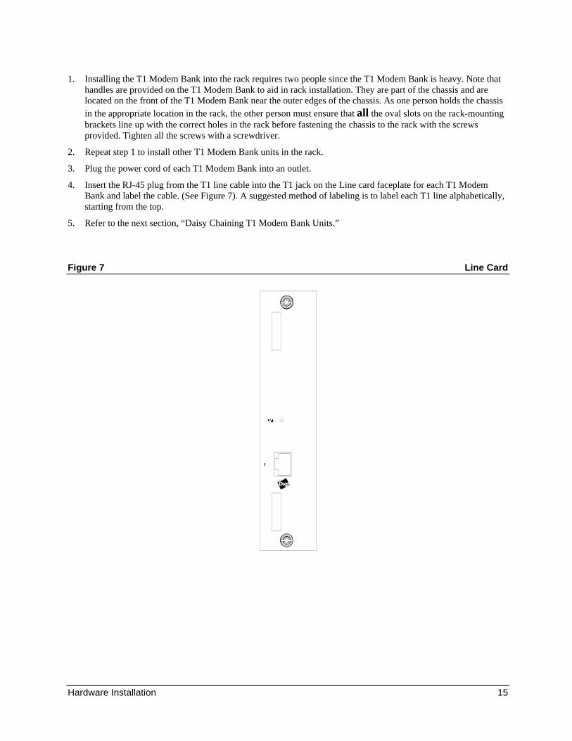
1. If the display panel faceplate on the T1 Modem Bank is closed, loosen the two captive screws on the displaypanel faceplate; carefully pull down the hinged display panel faceplate.
2. Slide the power supply into an available slot. It may be necessary to apply some force to properly seat the powersupply.
3. Use the ON/OFF switch at the back of the T1 Modem Bank to power it up if it is not already powered-up. If youinstalled a second power supply into a unit while the unit was powered-up, no reset is needed because hot swapcapabilities are integrated on power supplies.
4. It may take a few seconds for the LED on the power supply board to light to indicate that the power supply isoperational.

T1 Modem Bank10
T1 Modem Bank Standalone or Rack Installation
You have the option of using the T1 Modem Bank in a standalone, table-top configuration or in a rack-mountedconfiguration. Directions for both configurations are provided in this section.
• Make sure the T1 Modem Bank is powered-down before you install it.
• Do not block the sides of the T1 Modem Bank since this will impede airflow.
• The T1 Modem Bank is shipped from the factory with four “feet” installed on the bottom ofthe unit. If you remove the feet, you must ensure that the T1 Modem Bank will have at least1U (1.75 inches) of clearance beneath it in order to prevent airflow from being impeded.

Hardware Installation 11
Standalone Installation Procedure
Tools needed: Phillips screwdriver; flat blade screwdriver
1. Place the T1 Modem Bank on a flat surface within 6’ 7” (2m) of a power outlet.
2. Attach the terminator plug to the connector labeled HOST OUT on the HOST IN/OUT and Terminal faceplate.See Figure 3.
3. Plug the power cord into an outlet.
5. Insert the RJ-45 plug on the T1 line cable into the jack marked T1 on the Line card faceplate. See Figure 3.
6. Refer now to the instructions in “EPC/X Host Adapter Installation” on page 19.
Figure 3 Line Card and Synchronous Cable Connections for Standalone T1 Modem Bank
+267 287
7(50,1$/
3:5
7
&RQQHFWLRQ IRU 7 /LQH
7HUPLQDWRU 3OXJ WR EH LQVWDOOHG KHUH

T1 Modem Bank12
Requirements for Rack Installations
The T1 Modem Bank chassis is made to be inserted into a standard 19-inch or a 24-inch equipment rack. The T1Modem Bank is shipped from the factory with two rack-mounting brackets (“ears”) installed for a 19-inch rack. Ifyou wish to install a T1 Modem Bank into a 19-inch rack, go now to the instructions in “General Rack InstallationDirections” on page 14. Before you can install a T1 Modem Bank into a 24-inch rack, you must first remove therack-mounting brackets and then re-install them in the correct position for a 24-inch rack.
Mounting Bracket Installation for a 24-inch Rack
Tools needed: Phillips screwdriver; flat blade screwdriver
1. The rack-mounting brackets must be removed from their 19-inch rack position. Remove the three screws thatfasten each of the brackets to the chassis. (See Figure 4).
Figure 4 Bracket Position For 19-inch Rack
2. Re-install the brackets so that the long sides of the brackets extend outward from the chassis; the shorter sides ofthe brackets must be flat against the sides of the chassis as shown in Figure 5.

Hardware Installation 13
3. Line up the circular holes in a bracket with the circular holes on a side of the T1 Modem Bank, and use two ofthe screws to fasten the bracket to the chassis.
Do not use the oval slots on a bracket to connect the bracket to the T1 Modem Bank.
Figure 5 Bracket Position For 24-inch Rack
4. Follow “General Rack Installation Directions” on page 14 when you have installed two brackets to each T1Modem Bank unit.

T1 Modem Bank14
General Rack Installation Directions
• When multiple units will be mounted in the rack, install a T1 Modem Bank unit in
the first chassis slot at the bottom of the rack, then work upward. This preventscables from becoming tangled, and it maintains the lowest possible center of gravityto prevent the rack from falling over.
• Multiple T1 Modem Bank units within the confined space of a rack may causehigher operating temperatures. The recommended maximum external ambientoperating temperature of a T1 Modem Bank unit is 40° C. Since the T1 ModemBank takes in air from the vent on the bottom of the unit and exhausts the air outthe vent on the side, make sure that neither vent is blocked. The T1 Modem Bank isshipped from the factory with four “feet” installed on the bottom of the unit. If youremove the feet, you must ensure that each T1 Modem Bank will have at least 1U(1.75 inches) of clearance beneath it in order to prevent airflow from beingimpeded. You may connect a Digi-supplied spacer (See Figure 6) to the rackbetween each T1 Modem Bank unit in order to ensure the required clearance. Ingeneral, eight T1 Modem Bank units can be stacked in a six-foot rack; five unitscan be stacked in a 4-foot rack.
• The power cord is limited to 6’ 7” (or 2 m) in length. This is sufficient since mostracks provide internal power outlets.
• The T1 Modem Bank is rated at 1.2 Amps when the current is drawn from a 125 VAC supply. Due to the nature of the internal switching power supply, the powerrating of the AC supply circuit should be derated to 75% of its rated capacity whencalculating how many units can be connected to the AC supply. For example, a 15Amp circuit should be derated to 11.25 Amps.
• The T1 Modem Bank should be used only with earth grounded outlets. The earthground connection of the three prong cord should be maintained even when the unitis not connected directly to the AC supply line through a power strip.
Figure 6 T1 Modem Bank Unit Spacer
Hardware Installation 15
1. Installing the T1 Modem Bank into the rack requires two people since the T1 Modem Bank is heavy. Note thathandles are provided on the T1 Modem Bank to aid in rack installation. They are part of the chassis and arelocated on the front of the T1 Modem Bank near the outer edges of the chassis. As one person holds the chassisin the appropriate location in the rack, the other person must ensure that all the oval slots on the rack-mountingbrackets line up with the correct holes in the rack before fastening the chassis to the rack with the screwsprovided. Tighten all the screws with a screwdriver.
2. Repeat step 1 to install other T1 Modem Bank units in the rack.
3. Plug the power cord of each T1 Modem Bank into an outlet.
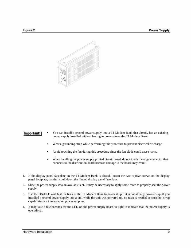
4. Insert the RJ-45 plug from the T1 line cable into the T1 jack on the Line card faceplate for each T1 ModemBank and label the cable. (See Figure 7). A suggested method of labeling is to label each T1 line alphabetically,starting from the top.
5. Refer to the next section, “Daisy Chaining T1 Modem Bank Units.”
Figure 7 Line Card
3:5
7
T1 Modem Bank16
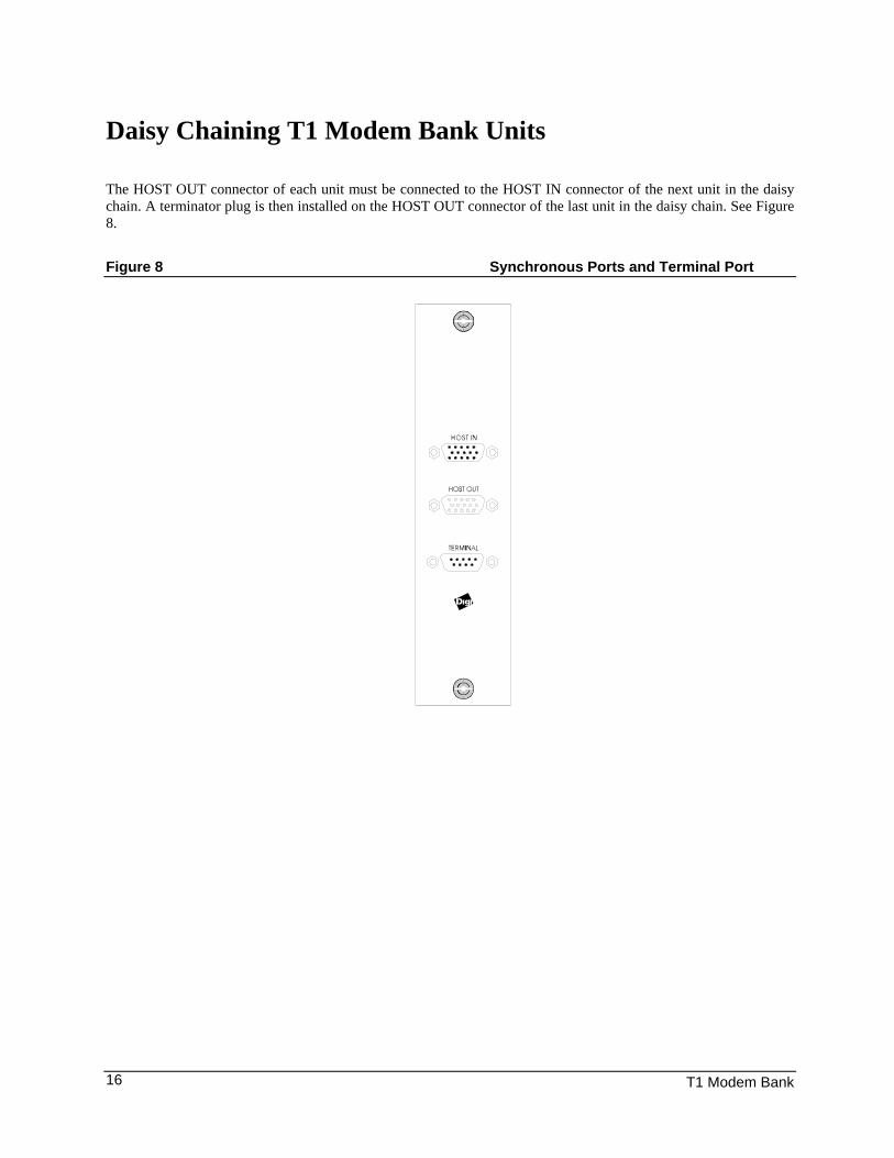
Daisy Chaining T1 Modem Bank Units
The HOST OUT connector of each unit must be connected to the HOST IN connector of the next unit in the daisychain. A terminator plug is then installed on the HOST OUT connector of the last unit in the daisy chain. See Figure8.
Figure 8 Synchronous Ports and Terminal Port
Hardware Installation 17
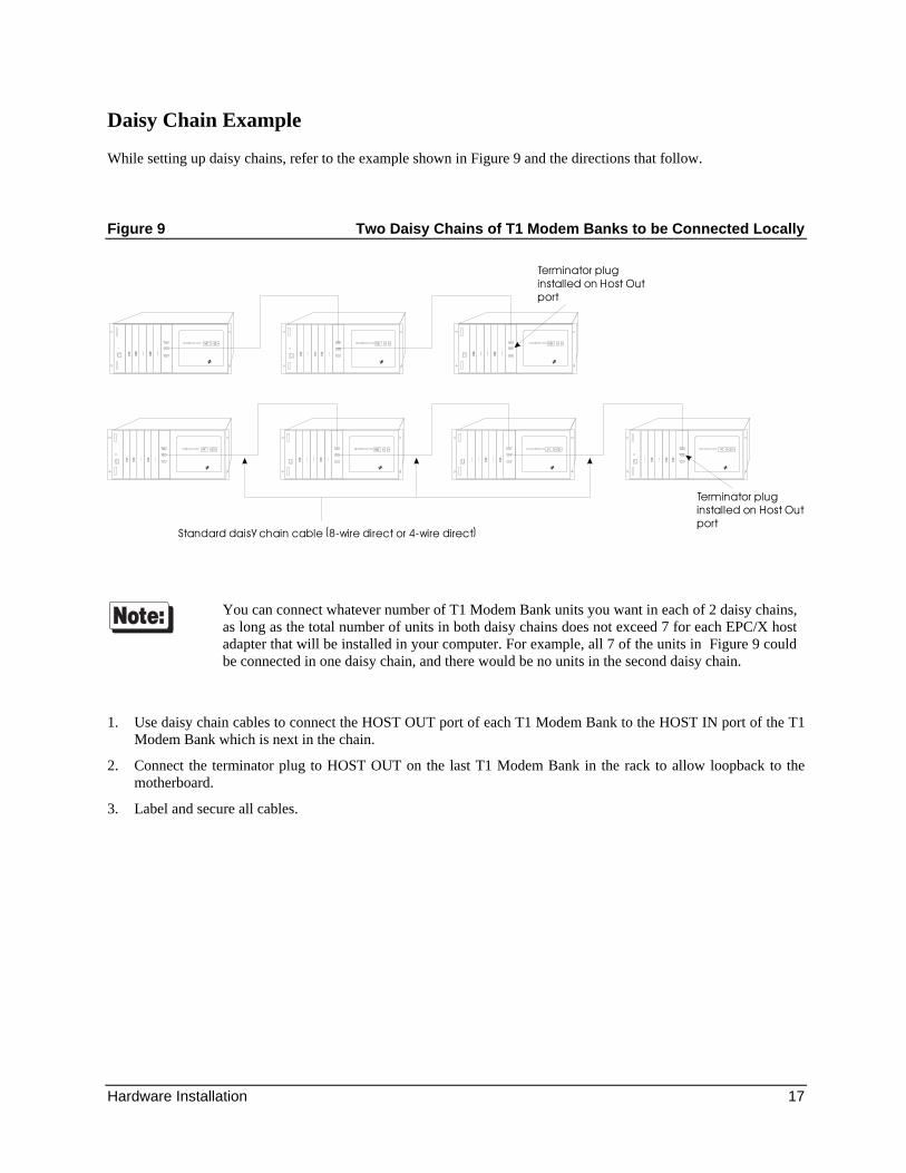
Daisy Chain Example
While setting up daisy chains, refer to the example shown in Figure 9 and the directions that follow.
Figure 9 Two Daisy Chains of T1 Modem Banks to be Connected Locally
T M
T M T M T M T M
T MT M
7HUPLQDWRU SOXJ
LQVWDOOHG RQ +RVW 2XW
SRUW
7HUPLQDWRU SOXJ
LQVWDOOHG RQ +RVW 2XW
SRUW6WDQGDUG GDLV\ FKDLQ FDEOH ZLUH GLUHFW RU ZLUH GLUHFW
You can connect whatever number of T1 Modem Bank units you want in each of 2 daisy chains,as long as the total number of units in both daisy chains does not exceed 7 for each EPC/X hostadapter that will be installed in your computer. For example, all 7 of the units in Figure 9 couldbe connected in one daisy chain, and there would be no units in the second daisy chain.
1. Use daisy chain cables to connect the HOST OUT port of each T1 Modem Bank to the HOST IN port of the T1Modem Bank which is next in the chain.
2. Connect the terminator plug to HOST OUT on the last T1 Modem Bank in the rack to allow loopback to themotherboard.
3. Label and secure all cables.

T1 Modem Bank18
• Do not connect wires to pins 12 or 13 in a standard daisy chain cable—serious damagecould result.
• Never use VGA extension cable or any other cable that has all 15 pins wired.
• Do not use a standard DB15 video cable
• To build a custom daisy chain cable, follow the wiring mode shown in Figure 33 on page94 or Figure 34 on page 95. Alternatively, contact your Digi sales representative.
Connecting a ModemTo connect a modem to T1 Modem Banks, use the cabling shown in Figure 35 (page 97) or Figure 36 (page 98),depending upon your modem type (RS-232 or RS-422). Connect additional T1 Modem Bank units with Eight-WireDirect cables (or the standard daisy chain cables shipped with the unit) as shown in Figure 10. Be sure to install theterminator plug on the HOST OUT port of the last T1 Modem Bank.
Figure 10 Remote T1 Modem Bank Units
T M T M T M
7HUPLQDWRU SOXJ
LQVWDOOHG RQ +RVW 2XW
SRUW
6' 5' &' 2+ 75
0RGHP 7HFK )$67 0RGHP 9
6\QFKURQRXV 0RGHP
6WDQGDUG GDLV\ FKDLQ FDEOH
PXVW EH ZLUH GLUHFW
6\QFKURQRXV PRGHP FDEOH
PRGHP WR 70RGHP %DQN

Hardware Installation 19
Daisy Chaining T1 Modem Bank Units and EPC/CON-16 Concentrators
A T1 Modem Bank can be installed in an existing system comprised of EPC/CON-16 concentrators. See Figure 11.
• Because existing EPC concentrators are assigned node numbers by the host each time the
software is booted, any added T1 Modem Bank units must follow the EPC concentrators inthe daisy chain.
• The last T1 Modem Bank in a daisy chain must have a terminator plug installed on itsHOST OUT port. Individual T1 Modem Bank units are not shipped with terminator plugs.Terminator plugs are shipped with EPC/X host adapters only.
• All EPC concentrators which will be connected to the EPC/X host adapter via synchronousmodems must be of the newer type (plastic) if a T1 Modem Bank is to be added to thesystem.
Figure 11 Mixing EPC Concentrators with T1 Modem Bank Units
T M
7HUPLQDWRU SOXJ
LQVWDOOHG RQ +RVW 2XW
SRUW
7' 5' 576 &76 ' 65 '&' '75 5, 2)& ,) &
(3&&21 7' 5' 576 &76 '65 '&' '75 5, 2)& ,)&
(3&&21 7' 5' 576 &76 '6 5 '&' ' 75 5, 2 )& , )&
(3&&21
(3& &RQFHQWUDWRU(3& &RQFHQWUDWRU(3& &RQFHQWUDWRU 7 0RGHP %DQN
Fault Tolerance
T1 Modem Bank units are assigned physical node numbers (set by the operator during installation—see page 27).The node number is used to route data to and from a specific T1 Modem Bank unit. If a particular T1 Modem Bankis turned off or removed from the daisy chain, the 24 channels on that T1 Modem Bank become unavailable to thesystem, but the rest of the system remains unaffected. Since the T1 Modem Bank unit’s HOST IN and HOST OUTports are of the opposite gender, a T1 Modem Bank can be removed from the middle of a daisy chain, and the cablescan be connected so that the chain remains unbroken. To remove the last T1 Modem Bank unit, simply plug aterminator plug into the end of the daisy chain cable.
When the hook-up is complete, go to “EPC/X Host Adapter Installation” on page 19 for further instructions.

T1 Modem Bank20
EPC/X Host Adapter Installation
The Digi EPC/X host adapter is an intelligent dual-channel synchronous communication board which plugs into aslot in your computer’s bus. The adapter provides an interface between the computer and a single T1 Modem Bankor a series of daisy-chained T1 Modem Banks and/or EPC concentrators.
Before installing your Digi EPC/X host adapter, be sure to write down its serial number.
PCI Host Adapters
Configuring the Host Adapter
No hardware configuration is required for PCI host adapters.
Installing the PCI Host Adapter in your Computer
1. Turn off your computer’s power and remove the cover. Refer to your computer’s manual for instructions oncover removal and option board installation and cautions.
2. Locate an available PCI slot in your computer and remove the slot plate.
3. Plug the host adapter into the PCI slot and screw the endplate to the computer chassis.
4. Replace your computer’s cover.
PCI EPC/X host adapters are shipped with a diagnostic diskette. The MS-DOS based diagnosticprogram, UD-PCI.EXE , will help verify correct installation of the host adapter, and helpidentify possible hardware problems. See the text file, USERPCI.TXT, for completeinstructions, and RELNOT-P.TXT for release information.
5. When you have verified that the host adapter has been correctly installed, follow the instructions in “Connectingthe EPC/X Host Adapter to the T1 Modem Banks” on page 25.

Hardware Installation 21
ISA Host Adapters
Setting the I/O Port Address
The ISA EPC/X host adapter uses four bytes of address space on the host computer’s I/O bus. Before installing thehost adapter, the board’s I/O port starting address must be set on DIP switch SW1 (located on the top of the board).To insure flexibility, seven I/O port address ranges are available: 108h-10Bh, 118h-11Bh, 128h-12Bh, 208h-20Bh,228h-22Bh, 308h-30Bh and 328h-32Bh. Choose one of the starting addresses and set SW1-1, 2 and 3 as shown inFigure 12 below.
Figure 12 DIP Switch Settings for I/O Port Address
1 2 3 4
OFF
108h
1 2 3 4
OFF
118h
1 2 3 4
OFF
128h
1 2 3 4
OFF
208h
1 2 3 4
OFF
228h
1 2 3 4
OFF
308h
1 2 3 4
OFF
328h
Record the I/O port address that you set. You will need to know the address when you installthe device driver.

T1 Modem Bank22
Factory-Set Jumper J1
There is one jumper, J1, on the host adapter. This jumper is set in the factory and must not be changed.
Installing the ISA Host Adapter in your Computer
1. Turn off your computer’s power and remove the cover. Refer to your computer’s manual for instructions oncover removal and option board installation and cautions.
2. Locate an available 16-bit AT slot in your computer and remove the slot plate.
3. Plug the host adapter into the ISA slot and screw the endplate to the computer chassis.
4. Replace your computer’s cover.
5. Go to “Connecting the EPC/X Host Adapter to the T1 Modem Banks” on page 25.
Hardware Installation 23
EISA Host Adapters
Factory-Set Jumpers
There are three jumpers, J1-J3 on the EISA EPC/X host adapter. These are set in the factory, and must not bechanged.
Installing the EISA Host Adapter in your Computer
1. Turn off your computer and disconnect any attached peripheral devices.
2. Remove the cover from the computer. Refer to your system’s documentation for cover removal instructions andfor other add-in board installation instructions and precautions.
3. Unscrew and remove the external slot cover plate from the slot into which you wish to install the EPC/X hostadapter.
4. Carefully insert the EPC/X host adapter into the slot in the computer. Press the board firmly into the EISA busconnector, and replace the screw in the host adapter’s endplate.
5. Replace the computer’s cover.
System Configuration
1. Boot up your EISA system with the EISA Configuration Diskette. During the boot-up process, the systemshould display a message to the effect that an unknown board has been found. This is the EPC/X host adapter in-stalled in the previous procedure.
2. When the boot-up has been completed, copy the file !DBI0301.CFG from the Digi distribution diskette toyour EISA system’s Configuration Diskette.
3. Run the configuration program to add the EISA host adapter.
4. From the Edit pull-down menu, select Add. The program will display a list of the .CFG configuration files forboards; select EPC/X Host Adapter. (If this is not displayed as an option, you may not have copied the .CFGfile to the correct directory in Step 2.
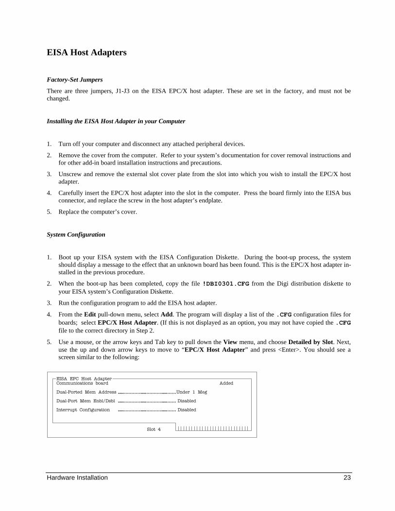
5. Use a mouse, or the arrow keys and Tab key to pull down the View menu, and choose Detailed by Slot. Next,use the up and down arrow keys to move to “EPC/X Host Adapter” and press <Enter>. You should see ascreen similar to the following:

T1 Modem Bank24
6. Place the cursor on “Dual-Ported Mem Address” and press <Enter>. A screen similar to the following willappear:
The following address choices are available:
Below 1 Megabyte:*80000h 88000h 90000h 98000hA0000h A8000h B0000h B8000hC0000h C8000h D0000h D8000hE0000h E8000h F0000h F8000h
Above 1 Megabyte:F0000000h F1000000h F2000000h F3000000hF4000000h F5000000h F6000000h F7000000hF8000000h F9000000h FA000000hFB000000hFC000000h FD000000hFE000000h FF000000h
* Although there are 16 choices offered for memory start addresses below 1 megabyte, a limited number of thesechoices is likely to be available. Of the 16, the best choices are probably D0000 and D8000. See Appendix Aon page 85 for more information.
Multiple EISA EPC/X host adapters may share the same addresses.
7. Use the cursor keys to select one of the listed addresses, or press <Enter> to accept what the configuration pro-gram has chosen. Write this address down—you will need to know it when installing the device driver soft-ware.
8. Leave the Dual-Port Mem Enbl/Dsbl at “Disabled”.
9. Leave the Interrupt Configuration at “Disabled”.
10. Pull down the SYSTEM menu, and choose “Exit ”. Make sure that you SAVE the new configuration as theprogram suggests.
11. Go to “Connecting the EPC/X Host Adapter to the T1 Modem Banks” on page 25.

Hardware Installation 25
Connecting the EPC/X Host Adapter to the T1 ModemBanks
To locally connect the EPC/X Host Adapter to the T1 Modem Bank(s), connect the daisy chain cable from theEPC/X host adapter line connector to the HOST IN connector on the first T1 Modem Bank in the daisy chain. (SeeFigure 13.) At the T1 Modem Bank end, label the cable “to Host EPC.”
Figure 13 EPC/X Host Adapter Connected Locally to T1 Modem Banks
'%, $1 5(9 61
T M
TM T M T M TM
T MT M
/LQH
/LQH (3&; +RVW $GDSWHU
6WDQGDUG GDLV\ FKDLQ FDEOH ZLUH GLUHFW RU ZLUH GLUHFW
If only one EPC/X host adapter synchronous line is to be used, it must be line 1the bottomconnector.
T1 Modem Bank26
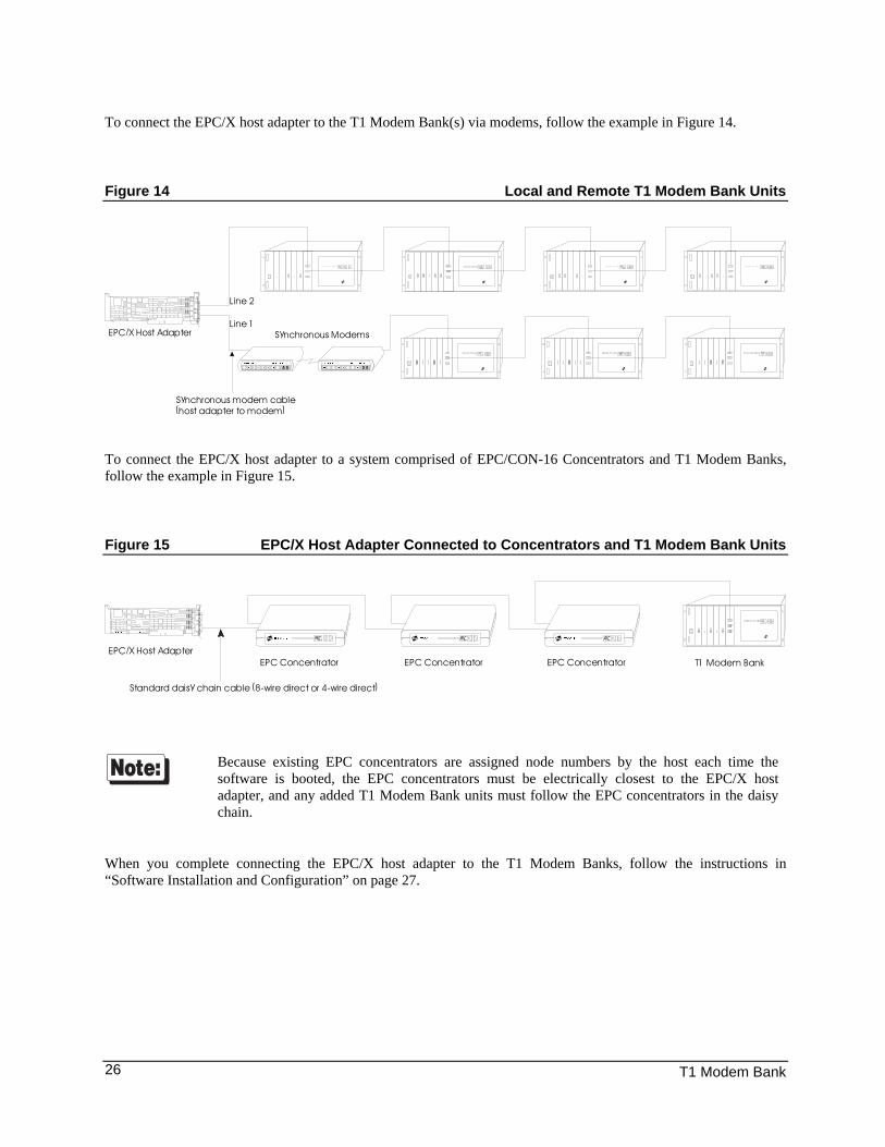
To connect the EPC/X host adapter to the T1 Modem Bank(s) via modems, follow the example in Figure 14.
Figure 14 Local and Remote T1 Modem Bank Units
'%, $1 5(9 61
T MT M
T M T M T M
T MT M
/LQH
/LQH (3&; +RVW $GDSWHU
6' 5' &' 2+ 75
0RGHP 7HFK )$67 0RGHP 9
6' 5' &' 2+ 75
0RGHP 7HFK )$67 0RGHP 9
6\QFKURQRXV 0RGHPV
6\QFKURQRXV PRGHP FDEOH
KRVW DGDSWHU WR PRGHP
To connect the EPC/X host adapter to a system comprised of EPC/CON-16 Concentrators and T1 Modem Banks,follow the example in Figure 15.
Figure 15 EPC/X Host Adapter Connected to Concentrators and T1 Modem Bank Units
'%, $1 5(9 61
TM
(3&; +RVW $GDSWHU
7' 5' 576 &76 '65 '&' '75 5, 2 )& ,)&
(3&&21 7' 5' 576 & 76 '65 '&' '75 5, 2 )& , )&
(3&&217' 5' 576 &76 '65 '&' '75 5 , 2)& ,)&
(3&&21
(3& &RQFHQWUDWRU(3& &RQFHQWUDWRU(3& &RQFHQWUDWRU 7 0RGHP %DQN
6WDQGDUG GDLV\ FKDLQ FDEOH ZLUH GLUHFW RU ZLUH GLUHFW
Because existing EPC concentrators are assigned node numbers by the host each time thesoftware is booted, the EPC concentrators must be electrically closest to the EPC/X hostadapter, and any added T1 Modem Bank units must follow the EPC concentrators in the daisychain.
When you complete connecting the EPC/X host adapter to the T1 Modem Banks, follow the instructions in“Software Installation and Configuration” on page 27.

Software Installation 27
Software Installation and Configuration
Setting the Node Number
The EPC/X host adapter identifies T1 Modem Bank units and/or EPC concentrators by their node numbers, whichare stored in non-volatile RAM (NVRAM). Each T1 Modem Bank and concentrator in a daisy chain must have aunique node number which must be set during installation. The node numbers must be assigned in ascending orderwith the lowest number assigned to the T1 Modem Bank or concentrator closest to the EPC/X host adapter. It ispermissible to skip node numbers to facilitate insertion of additional T1 Modem Bank units at a later date as long asthe ascending sequence is maintained. If node numbers are not skipped, the node numbers of added T1 Modem Bankunits must begin with a number that is greater than the total number of existing T1 Modem Bank units and/or EPCconcentrators in a daisy chain.
When setting up remote T1 Modem Bank units, the node number of the last T1 Modem Bank ona sync line must be the same as the total number of T1 Modem Bank units that will beconfigured in the device driver software for that line. This is because the clocking mode for thelast T1 Modem Bank is set by the device driver software for synchronous modem clocking. Ifthe device driver has been configured for six T1 Modem Bank units on a sync line, the nodenumber of the last T1 Modem Bank must be set to 6, regardless of the actual number of T1Modem Bank units that are physically present on that line.
Similarly, fault tolerance is not effective if the last T1 Modem Bank of a remote string fails,because the software only programs that T1 Modem Bank, by its node number, for synchronousmodem clocking. The other T1 Modem Banks are all set for regular (8-wire direct) clocking. Ifthe last T1 Modem Bank in a remote string fails or is removed for any reason, you must eitherreconfigure the device driver software for one less T1 Modem Bank, or change the node numberof the next-to-last T1 Modem Bank to the number of the T1 Modem Bank that was removed. Ifyou change a T1 Modem Bank's node number, be sure to reboot the T1 Modem Bank (poweroff and then on) so that the host system can reinitialize it properly.
Node numbers must be correctly assigned in order for the T1 Modem Bank to properly function. If there is aproblem, the COM port assignment may be incorrect, or two nodes may have been assigned the same number. Thissituation may arise if T1 Modem Bank units are swapped or moved, but the node numbers are not changed.
To set the node number on a T1 Modem Bank, activate the T1 Modem Bank by setting the power switch on the rearof the chassis to the ON (|) position. Soon after the lights on the display panel flash, press the right push button onthe display panel (see Figure 16 on page 28) until the current setting is displayed (1n if directly from the factory).
To avoid an error condition during the power-on self test (POST) of a T1 Modem Bank thatyou’ve added to existing T1 Modem Bank units and/or EPC Concentrators in a daisy chain, youmust change the T1 Modem Bank’s 1n (Node 1) factory configuration. Make sure you press theright push button on the display panel before POST is completed.

T1 Modem Bank28
Figure 16 T1 Modem Bank Display Panel
Pressing the right push button will interrupt the power-on self test (POST) of a T1 Modem Bank and let you enterthe configuration/diagnostic mode so that you can change the T1 Modem Bank’s node number. Press the left pushbutton until your desired node number is displayed, then press the right push button to set the node number.
Software Installation 29
Installing Download
Cycle the T1 Modem Bank’s power off, then on again to restart POST. After a brief pause, the lights on the displaypanel will flash, and the T1 Modem Bank will begin the POST sequence, which takes about 2 minutes to complete.Once the POST is completed, P1 will be shown on the display panel to indicate that the T1 Modem Bank is readyfor download. (If P1 is not shown, go to the section “POST Failure” on page 30 for instructions.)
P2 indicates that the PING signal has been received; P3 will flash briefly on the screen, indicating that the downloadhas started. P4 indicates that a download is underway. At the same time, the LEDs will blink as packets are counted.The following sequence appears on the display panel: PE, D0, C1, C2, C3, C4. When the download is received andif the checksum has been validated, AC is then shown in the display, indicating that the T1 Modem Bank has beenprogrammed, FEP is running, and the T1 Modem Bank is on-line. At this point, go to either “Software Installationfor Novell Systems” on page 34 or “Software Installation for Windows NT Systems” on page 38.
T1 Modem Bank30
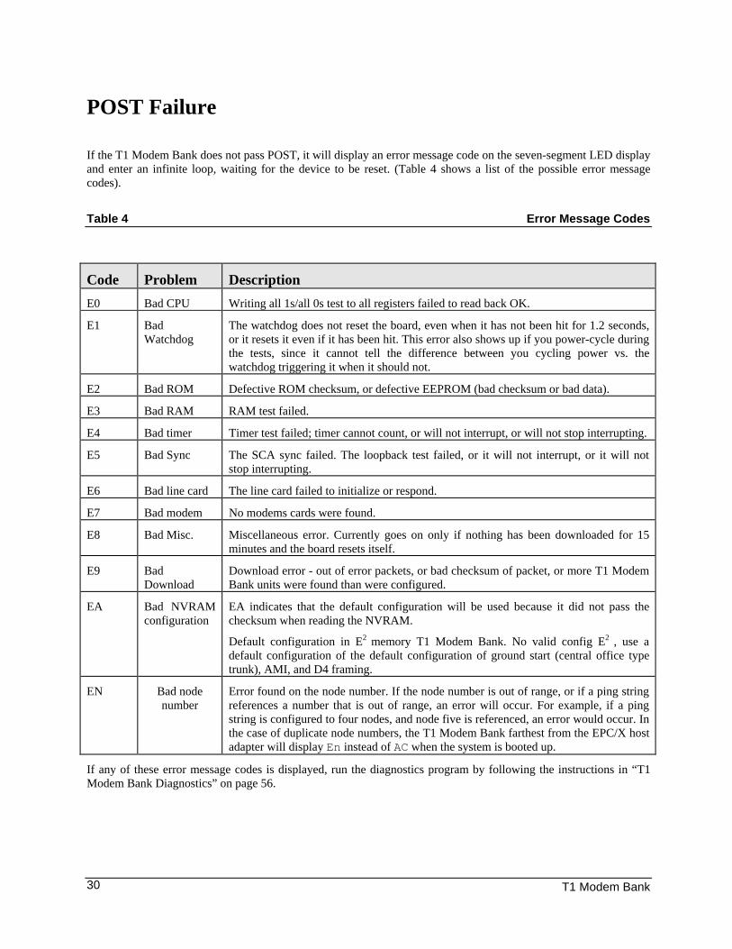
POST Failure
If the T1 Modem Bank does not pass POST, it will display an error message code on the seven-segment LED displayand enter an infinite loop, waiting for the device to be reset. (Table 4 shows a list of the possible error messagecodes).
Table 4 Error Message Codes
Code Problem Description
E0 Bad CPU Writing all 1s/all 0s test to all registers failed to read back OK.
E1 BadWatchdog
The watchdog does not reset the board, even when it has not been hit for 1.2 seconds,or it resets it even if it has been hit. This error also shows up if you power-cycle duringthe tests, since it cannot tell the difference between you cycling power vs. thewatchdog triggering it when it should not.
E2 Bad ROM Defective ROM checksum, or defective EEPROM (bad checksum or bad data).
E3 Bad RAM RAM test failed.
E4 Bad timer Timer test failed; timer cannot count, or will not interrupt, or will not stop interrupting.
E5 Bad Sync The SCA sync failed. The loopback test failed, or it will not interrupt, or it will notstop interrupting.
E6 Bad line card The line card failed to initialize or respond.
E7 Bad modem No modems cards were found.
E8 Bad Misc. Miscellaneous error. Currently goes on only if nothing has been downloaded for 15minutes and the board resets itself.
E9 BadDownload
Download error - out of error packets, or bad checksum of packet, or more T1 ModemBank units were found than were configured.
EA Bad NVRAMconfiguration
EA indicates that the default configuration will be used because it did not pass thechecksum when reading the NVRAM.
Default configuration in E2 memory T1 Modem Bank. No valid config E2 , use adefault configuration of the default configuration of ground start (central office typetrunk), AMI, and D4 framing.
EN Bad nodenumber
Error found on the node number. If the node number is out of range, or if a ping stringreferences a number that is out of range, an error will occur. For example, if a pingstring is configured to four nodes, and node five is referenced, an error would occur. Inthe case of duplicate node numbers, the T1 Modem Bank farthest from the EPC/X hostadapter will display En instead of AC when the system is booted up.
If any of these error message codes is displayed, run the diagnostics program by following the instructions in “T1Modem Bank Diagnostics” on page 56.
Software Installation 31
Possible Problem
If at least one modem card is not inserted in the T1 Modem Bank unit, the line card will busy out the linesassociated with that line card.
Restarting POST
Cycle the T1 Modem Bank’s power off, then on again to restart POST.
Display Panel Status Indicators
Once the POST is completed, P1 will be shown on the display panel to indicate that the T1 Modem Bank is readyfor download. P2 indicates that the PING signal has been received; P3 will flash briefly on the screen, indicatingthat the download has started. P4 indicates that a download is underway. At the same time, the LEDs will blink aspackets are counted.
The following sequence appears on the display panel: PE, D0, C1, C2, C3, C4. When the download is received andif the checksum has been validated, AC is then shown in the display, indicating that the T1 Modem Bank has beenprogrammed, FEP is running, and the T1 Modem Bank is on-line. At the same time, the LEDs on the display panelwill appear to march one by one through the display panel LEDs. This process takes about 30 seconds. The user canthen push the right or left arrow push buttons to cycle sequentially through the displays which are described in Table5. The left push-button is used to program the T1 Modem Bank; the right is used to scroll through and locate thedesired mode.
There are several classes of LED displays that appear on the display panel. Each class has a different meaning, asdescribed below:
• CSU (Channel Service Unit) display the text for CSU display is vertically positioned and appears as follows:AMI/B8ZS SF/ESF RED YELLOW BLUE L LOOP R LOOP CSU/DSX-1 D&I LOS. See the L1description in Table 5.
• Channel variablethe seven-segment channel number indicates the node number of each modem found,ranging from 1 - 24. The text for the data and handshake signals is marked as TD RD RTS CTS DSRDCD DTR RI OFC IFC just above the LEDs on the display panel faceplate. See the CHAN # descriptionin Table 5.
• Countersencompass all other displays shown (See Table 5.) These counters use a percentage ranging from 0to 100%, (shown below the LEDs in Figure 16 on page 28) and indicate line utilization, packet count, errors persecond, processor utilization, and so on. Counters may be reset to 0 by pressing both buttons simultaneously.Counters provide a rough magnitude number. If more information is needed, QuickManager must be used.

T1 Modem Bank32
Table 5 Display Panel Status Codes
7 SegmentDisplay
Meaning Description
AC Activity AC appears on the 7-segment display. The ten activity LEDs turn on sequentially from left to right.The speed of this “chase light” display increases with the overall activity level of the T1 ModemBank.
LU Line Utilization LU appears on the 7-segment display, and the ten LEDs become a bar graph indicating thepercentage (0-100%) of the time the synchronous communications line is being used.
PU Processor Utilization PU appears on the 7-segment display, and the ten LEDs become a bar graph indicating the percentage(0-100%) of the time the T1 Modem Bank’s microprocessor is being used.
PC Packet Count PC appears on the 7-segment display, and the ten LEDs show a binary representation of the totalnumber of packets transmitted or received on the sync line between the EPC/X host adapter and theT1 Modem Bank. Pressing both push-buttons simultaneously resets the count to 0.
EC Error Count EC appears on the 7-segment display, and the ten LEDs show a binary representation of the totalnumber of errors counted on the sync line between the EPC/X host adapter and the T1 Modem Bank.This indicates the quality of the line. Pressing both push-buttons simultaneously resets the count to 0
L1* T1 Line Card Status L1 appears on the 7-segment display and corresponds to the vertically positioned text. LEDfunctions are as follows:
• for AMI/B8ZS, AMI is indicated when the LED is lit, B8ZS is indicated when the LED is unlit.• for SF/ESF, SF is indicated when the LED is lit, ESF is indicated when the LED is unlit.• for CSU/DSX-1, CSU is indicated when the LED is lit, DSX-1 is indicated when the LED is
unlit.• The RED, BLUE and YELLOW LEDs will be lit if there is a red, blue, or yellow alarm
currently active on the T1 line.• The LLOOP LED will be lit if the remote switch has placed the line card in local loopback
mode.• The RLOOP LED will be lit if the remote switch has placed the line card in remote loopback
mode.• D&I represents drop and insert.
• LOS indicates loss of signal from the T1 line.
ES* Errored Seconds An Errored Second is a second with one or more Error Events
Cr* CRC Errors A CRC error occurs when the CRC calculated by the T1 Modem Bank does not agree with the CRCreceived from the network.
bS* Bursty ErroredSeconds
A Bursty Errored Second is a second with more than one, but less than 320 CRC errors.
EE* Error Events A CRC error or a Loss Of Frame event

Software Installation 33
Table 5 (continued)
7 SegmentDisplay
Meaning Description
SE* Severely ErroredSeconds
A Severely Errored Second is a second with 320 or more CRC errors
FS* Framing Bit Errors An error in the Framing Bits received from the network
LF* Line FormatViolations
In AMI mode, any bipolar violation; in B8ZS mode, any invalid bipolar violation. A bipolar violationis an error in the encoding of binary 1’s and 0’s received from the network.
CHAN Display channels This display designates channel variables. The channel number appears on the 7-segment display.The ten LEDs correspond to the first row of labels on the front panel (TD, RD, RTS, CTS, and soon). The user may scroll through the 24 channels using the right push-button. The 7-segment displayindicates which channel has been accessed.
1n, 2n, 3n ...8n
Node Number The seven-segment display shows the node number of the T1 Modem Bank. Select the desired mode(1n through 8n) using the left push-button. Refer to “Setting the Node Number” on page 27. The tenLEDs behave as in the AC display mode.
* These status codes are related to the T1 (CSU) interface.
Go to either “Software Installation for Novell Systems” on page 34 or “Software Installation for Windows NTSystems” on page 38.

T1 Modem Bank34
Software Installation for Novell Systems
Introduction
Before software installation can proceed:
• The EPC/X adapters must be installed in the computer.• The T1 Modem Banks must be connected to the EPC/X host adapters.• The T1 Modem Banks must be powered on.• The T1 Modem Bank node numbers must be set.• A T1 line must be connected to the T1 connector on the line card of each T1 Modem Bank.
The driver will support up to four Digi EPC/X host adapters on ISA, EISA and PCI bus servers.
T1 Modem Banks and concentrators may be connected locally (direct wiring), or remotely (via high-speedsynchronous modems). This driver supports one modem pair per synchronous line, and the modems must be installedbetween the host adapter and the first device (concentrator or T1 Modem Bank) in the daisy chain. Local and remoteconcentrators/T1 Modem Banks may not be combined on a single synchronous line.
Software installation for a Novell system which is directly connected to the T1 Modem Banks involves the followingsteps:
1. The EPC/X Novell NetWare AIO (Asynchronous Input/Output) device driver must be installed and configured.
2. An AIO application like NetWare Connect, FaxServe, or Wanderlink should be installed on the system to whichthe T1 Modem Banks are directly connected.
3. SNMP (Simple Network Management Protocol) must be configured if you wish to manage the T1 ModemBanks remotely with the management software (“QuickManager”).
4. If you wish to remotely manage the T1 Modem Banks, install QuickManager on an NT system on your network.
QuickManager does not currently support SNMP under Windows 95. Therefore, you can notmanage a Novell system from a Windows 95 system.
5. Each T1 Modem Bank must be configured using DGT1CFG.NLM, QuickManager or the serial port.
Software Installation 35
Installing the EPC/X AIO Device Driver
See the AccelePort EPC/X device driver installation instructions in the Digi AccelePort Intelligent SerialCommunications Products Novell AIO Device Driver Package Software Manual (manual part no. 92000243). Thismanual is included with the T1 Modem Bank package.
Installing the AIO Application
Follow the instructions in the Novell manuals to install NetWare Connect on the system to which the T1 ModemBanks are directly connected. Alternatively, you can use another AIO application like Cheyenne FaxServe or FunkSoftware’s Wanderlink.
Installing SNMPSNMP is pre-installed on NetWare.
If you wish to manage the T1 Modem Banks remotely with QuickManager, you must follow these additional steps:
1. Configure the SNMP on the Novell system. This is done via the SNMP.NLM load line parameters or withinINETCFG.NLM. Please see the Novell documentation for instructions.
2. Install SNMP on a Windows NT system on the network. Use the following procedure to install SNMP on the
NT system:
a) Double click Control Panel.
b) Double click the Network icon.
c) When the “Network” window appears, select “Services”, then click the “Add” button.
d) Select “SNMP Service.”
Installing QuickManager
If you wish to manage the T1 Modem Banks remotely with QuickManager, you will need to install QuickManageron a Windows NT system on your network. Use the following procedure to install QuickManager:
1. Insert the T1 Modem Bank NT Setup Disk into drive A of the remote system operating under Windows NT.
2. Run A:\SETUP.EXE.

T1 Modem Bank36
Configuring the T1 Modem Banks
• The instructions for configuring and managing T1 Modem Banks with QuickManager are in “Configuring viaQuickManager” on page 41.
• Configuring the T1 Modem Banks with the DGT1CFG.NLM utility is described in this section.
Although the DGT1CFG.NLM utility will configure the T1 Modem Banks, it can not performmanagement functions like advanced configuration, monitoring, and testing. For completemanagement capability of your T1 Modem Banks, you must install and use QuickManager.
1. Make sure all T1 Modem Banks are powered on and display AC on their display panels.
2. Enter the following command:
load dgt1cfg.nlm
When the main menu appears, use the arrow keys to select the EPC/X host adapter that is connected to the T1Modem Banks you wish to configure. (See Figure 17 for an example screen). Note that the field “#T1 Banks”indicates how many modem banks are connected to that EPC/X host adapter.
Figure 17 Main Screen
All T1 Modem Banks should be ON and in the AC state before you select a board. If the T1Modem Banks are not in the AC state, default parameters will initially be displayed, and anychanges you make can not be saved. Instead, the default parameters will be saved. If the T1Modem Banks are not in the AC state, see the section titled “POST Failure” on page 30 forinstructions.

Software Installation 37
3. Press the ENTER key to configure that host adapter’s T1 Modem Banks. The “#” field in the example screenshown in Figure 18 indicates the number (beginning with 0) of the T1 Modem Bank you will be configuring.
Figure 18 T1 Modem Bank Configuration Screen
4. Use the arrow keys to select the field you wish to change, and press the ENTER key to view a list of the optionsthat are available for that field. Use the arrow keys to select the option you wish, and then press the ENTER keyagain to set the option for that field.
If you select SHORT for the “Span”, the “Length” field is in feet (0 to 655), and the “EQ” fieldis not applicable. If the span is LONG, then the “Length” field is in dB, and the “EQ” field isapplicable.
5. Once the desired settings have been selected, they must be applied to the T1 Modem Bank. Select the “ApplyConfig” field. A pop up box will indicate the success or the failure of implementing the setting assigned for eachparameter.
6. When you exit the program, you will be asked if you wish to save the current configuration. (If you applied allthe settings, this question is unnecessary). Responding “Yes” will save all parameters to all T1 Modem Banks.

T1 Modem Bank38
Software Installation for Windows NT Systems
Software installation and configuration for a Windows NT system involves the following steps:
1. Install and configure the EPC/X Windows NT device driver on the host system (the system to which the T1Modem Banks are directly connected).
2. Optionally install the Windows NT SNMP (Simple Network Management Protocol) service on the host system.If you plan to remotely manage the T1 Modem Bank via SNMP, install the SNMP service on the host prior toinstalling the management software.
3. Optionally install Windows NT RAS (Remote Access Service) on the host system. If you will be using RAS, itshould be installed on the host system prior to installing the management software.
4. Install the management software on the host system.
5. Optionally install the management software (QuickManager portion) on remote systems located on yournetwork. Remote systems must be running Windows NT or Windows 95. Windows 95 remote systems canmanage only Windows NT Server based host systems.
Installing the EPC/X Windows NT Device Driver
See the AccelePort EPC/X device driver installation instructions in the Digi Intelligent Serial CommunicationsBoards-Device Drivers for Microsoft Windows 95, Windows NT, Windows for Workgroups 3.11, Windows 3.1-Software Manual (manual part no. 92000220).
Installing the Windows NT SNMP Service
Windows NT 3.51
The SNMP Service is part of the TCP/IP package for Windows NT 3.51.
1. Double click Control Panel.
2. Double click the Network icon.
3. When the “Network” window appears, click the button “Add Software.”
4. From the drop down list, select “TCP/IP Protocol and Related Components.”
5. Click the “Continue” button.
6. Click the check box for “SNMP Service.”
7. Click the “Continue” button to complete the installation.
If TCP/IP was not installed prior to this, you must complete the installation by answering the TCP/IP specificquestions.

Software Installation 39
Windows NT 4.0
1. Double click Control Panel.
2. Double click the Network icon.
3. When the “Network” window appears, select “Services”, then click the “Add” button.
4. Select “SNMP Service.”
Installing RAS
Windows NT Remote Access Service (RAS) includes the following applications:
• Dial-Up Networking is the client version of RAS and is used to connect to dial-up servers. The Dial-UpNetworking icon is located in the My Computer dialog box and in the Accessories folder on the Start menu.
• Dial-Up Networking Monitor, used to monitor connections and devices, is located in Control Panel.
• Remote Access Admin, used to monitor remote users connecting to a RAS server, is located in theAdministrative Tools folder on the Start menu.
For more information about RAS, see the Microsoft Windows NT Server Installation Guide (Windows NT 3.5) or theMicrosoft Windows NT Server Networking Supplement (Windows NT 4.0). More information is available in the fileNETWORK.WRI located in the directory where NT is installed.
Installing the Management Software
The management software setup program (software package part no. 75000219) installs support for local and remotemanagement of the T1 Modem Banks connected to a host system. This software must be installed on the host systemand can optionally be installed on remote systems. Setup requires Windows NT or Windows 95.
Host System Installation
Host systems are Windows NT systems which have T1 Modem Banks and drivers installed. Remote management ofthe host system’s T1 Modem Banks is available via SNMP. SNMP management applications (includingQuickManager) may be used. For host systems running Windows NT Server, remote management from a Windows95 system is also possible via QuickManager.
Before running the setup program on the host system, check the following:
• The EPC/X driver is installed and running (reboot after driver installation).• Each T1 Modem Bank is connected and powered on.• Each T1 Modem Bank has completed its download (AC is displayed on the front panel). If
the T1 Modem Banks are not in the AC state, see the section titled “POST Failure” on page30 for instructions.
• The T1 line is ready to be connected to the T1 Modem Bank.• The list of operating parameters for the T1 line is available.• If SNMP or RAS will be used, be sure to install and configure these first.

T1 Modem Bank40
To run the setup program, insert the setup disk (part no. 40001468) into the drive and run SETUP.EXE.
Setup will perform the following steps:
1. Install local and remote management support files.
2. Install and run the ConfigWizard configuration utility.
3. Install and run the QuickManager management application.
4. Copy the SNMP MIBS (RFC1406, RFC1659 and DIGIT1E1. MIB).
5. Optionally install the Digi SNMP Proxy Agent.
When setup is complete, see the section “Configuring via QuickManager” on page 41.
Remote System Installation
Remote systems are systems running Windows NT or Windows 95 which will be used to remotely manage a hostsystem’s T1 Modem Banks. Using QuickManager, Windows 95 remote systems can manage only host systems thatare running Windows NT Server.
To run the setup program, insert the setup disk (part no. 40001468) into the driver and run SETUP.EXE.
Setup will perform the following steps:
1. Install the QuickManager management application.
2. Copy the SNMP MIBS (RFC1406, RFC1659 and DIGIT1E1.MIB).
When setup is complete, see the section “Configuring via QuickManager” on page 41.

Software Installation 41
T1 Modem Bank Configuration
The T1 Modem Bank can be configured in the field for specific network needs by one of four methods:
• QuickManager mode
• DGT1CFG.NLM mode (used on Novell systems only). See “Configuring the T1 Modem Banks” on page 36for instructions on using the DGT1CFG.NLM utility.
• terminal port mode
• display panel mode
It is easier and less time-consuming to configure a T1 Modem Bank using QuickManager or DGT1CFG.NLM thanto use the terminal port or the display panel. In addition, QuickManager can perform management functions likeadvanced configuration, monitoring, and testing.
Configuring via QuickManager
QuickManager is started by clicking the “Digi” program group, and then clicking the QuickManager icon. (Clickingthe ConfigWizard icon in the “Digi” program group allows you to initially configure the T1 Modem Banks, butConfigWizard does not perform the management functions that QuickManager does). Clicking “Window” in themain menu will allow you to view the current configuration settings, change the configuration settings, or run a teston the selected component. (You can alternatively click the applicable button below the main menu). Figure 19shows an example screen for the status of a line card.

T1 Modem Bank42
Figure 19 Line Card Status Display

Software Installation 43
Figure 20 shows an example screen when “Line Card” and “Options” are selected.
Figure 20 Line Card Options Display
Once the desired settings have been selected for a component, they must be applied to the T1 Modem Bank. Select“Apply” from the “Window” menu or click the “Apply” button.
T1 Modem Bank44
Configuring via the Terminal Port
To configure the T1 Modem Bank through the terminal port, follow these steps before startingup the T1 Modem Bank:
1. Make sure the T1 Modem Bank is shut off; then connect a terminal to the terminal port.Some terminals will not transmit data if their CTS (Clear To Send) line is LOW. Theseterminals must have their CTS line HIGH or floating to ensure that they will have noproblems communicating with the T1 Modem Bank. Appendix C on page 91 shows a cablethat can be used for these terminals.
2. Power up the terminal and set its communications parameters to 9600 baud, 8 data bits, noparity and 1 stop bit.
3. Power up the T1 Modem Bank and press ? on the terminal keyboard to bring up theconfiguration/diagnostic menu.
• Press N to set the node number
• Press L to set the line configuration
Press T for T1 line or D for Drop and Insert
If D, select a, b, c, d, or e (default a) a) .6 dB b) 1.2 dB c) 1.8 dB d) 2.4 dB e) 3.0 dB
If T, select a or b (default a) a) CSU Long Haul b) DSX-1 Short Haul
If CSU, select a or b (default a) a) AMI/D4 b) B8ZS/ESF
Select Jitter, EGL, or LBO
If Jitter, select a or b (default b) a) Tx b)Rx
If EGL, select a or b (default a) a) 26 dB b) 36 dB
If LBO, select a, b, c, or d (default d) a) 0 b) -7.5 c) -15.5 d) -22
If DSX-1, select a, b, c, d, or e (default a) a) .6 dB b) 1.2 dB c) 1.8 dB d) 2.4 dB e) 3.0 dB
By pressing <Enter> at any time, you may exit the configuration/diagnostic mode without saving any of yourchanges. The POST will then resume if it had not been completed at the time you entered configuration/diagnosticmode. If POST had been completed when you entered configuration/diagnostic mode, the download will begin whenyou exit configuration/diagnostic mode.
To exit the configuration/diagnostic mode and save your changes, cycle the T1 Modem Bank’s power off, then onagain to return to the initialized state.

Software Installation 45
Configuring via the Display Panel
Power up the T1 Modem Bank and press the right push button on the display panel soon after the adjacent lightsflash. Repeated pressing of the right push button will cycle through the following sequence:
(1) Node number selection
(2) T1 line configuration
(3) Diagnostic tests
Pressing the left push button will allow you to change the parameter whose current value or setting is shown in thedisplay panel.
The first thing shown on the display panel should be the T1 Modem Bank’s node number. This will be displayed inthe form xn , where x is the node number (1n , 2n , and so forth). (If the T1 Modem Bank has just been unpacked,1n , for Node 1, will be displayed). If you wish to change the node number, press the left push-button repeatedlyuntil the desired node number appears on the display panel, then press the right pushdown to save it in EEPROM. Ifthe new node number is successfully written to EEPROM, Pn will be displayed to indicate a pass condition. If thewrite operation failed, Fn will be displayed. See “Setting the Node Number” on page 27 for more information aboutnode numbers. If you do not wish to change the node number at this time, press the right push-button again toproceed to the Line Card configuration test.
T1 Modem Bank46
The following describes the display panel configuration/diagnostic process:
1. Press Right Displays current node number Press Left changes node number
2. Press Right Line Card T1 Line Select Press Left selects Line Interface or Drop & Insert
3. Press Right goes to Diagnostic Test 1 (if no left press at Line Card T1 Line Select)
4. Press Right if Drop & Insert Press Left changes EQ 0.6 1.2 1.8 2.4 3.0
5. Press Right goes to Diagnostic Test 1
6. Press Right if Line Interface Press Left selects CSU Long Haul or DSX-1 Short Haul
7. Press Right if CSU Long Haul Press Left selects AMI/D4 or B8ZS/ESF
8. Press Right either AMI/D4 or B8ZS/ESF Press Left selects Jitter, EGL, LBO
9. Press Right goes to Diagnostic Test 1 (if no left press to select Jitter, EGL, LBO)
10. Press Right if Jitter Press Left selects Rx or Tx
11. Press Right go to step 8 above
12. Press Right if EGL Press Left selects 26 or 36
13. Press Right go to step 8 above
14. Press Right if LBO Press Left selects 00 75 15 22
15. Press Right go to step 8 above
By pressing <Enter> at any time, you may exit the configuration/diagnostic mode without saving any of yourchanges. The POST will then resume if it had not been completed at the time you entered configuration/diagnosticmode. If POST had been completed when you entered configuration/diagnostic mode, the download will begin whenyou exit configuration/diagnostic mode.
To exit the configuration/diagnostic mode and save your changes, cycle the T1 Modem Bank’s power off, then onagain to return to the initialized state.

Software Installation 47
Configuring via the Serial Port Interface
The serial port on the T1 Modem bank can be used to display and modify the T1 configuration. It can also be used todisplay the installed equipment list, the modem on/off-hook status, and the alarm status. Thus there are 5 basicfunctions provided by the interface:
1. T1 interface configuration display and modification.
2. Alarm status display.
3. Modem signaling status display.
4. BIOS/NVRAM information
5. Installed equipment information
The T1 modem bank can be configured by a user via a terminal attached to serial port on the modem bank’s frontpanel. This configuration is limited to the following T1 interface parameters:
1. Frame format (D4/SF or ESF)
2. Line Coding (AMI or B8ZS)
3. Jitter attenuation path
4. T1 Robbed-bit signaling protocol
5. Span type (Short- or Long-haul)
There are also some context-dependent parameters that depend on the value chosen for the “Span type” parameter.These context parameters are “Line Build Out”, “Receiver Gain Limit” and “Line Length”.
To use the interface the user must provide a terminal and connect it to the serial port marked “terminal” on themodem bank’s front panel. The cable pinout should follow the standard PC DB-9 serial port pinout.
The interface also implements the XON/XOFF software flow control protocol. <Ctrl-S> may be typed at theattached terminal to interrupt any output from the modem bank to the terminal, and <Ctrl-Q> will cause any pausedtransmission to resume. The user can use the backspace/erase key to perform limited command line editing whenentering commands.
After the Modem bank is powered up and the system firmware downloaded, typically by a host-system OS driver,the modem bank’s current T1 configuration will be displayed along with a description of commands that the usermay enter.

T1 Modem Bank48
The initial screen is shown below.
----------------------------------------------------------------------------- Modem Bank Configuration ----------------------------------------------------------------------------- Parameter | Possible values <>=selected []=active ----------------------------------------------------------------------------- 1) T1 Frame Fmt. | D4 | [ESF ] | | | 2) Line Coding | AMI | [B8ZS ] | | | 3) Jitter Attn. | [Transmit ] | Receive | Auto | None | 4) T1 Sig. Prot. | GS | LS | [Immediate] | Wink | 5) Span Type | [Long ] | Short | | | 6) Line Build-Out | [0dB ] | -7.5dB | -15dB | -22.5dB | 7) Rcv Gain Limit | Low/26dB | [High/36dB] | | | -----------------------------------------------------------------------------
Please enter one of the following --------------------------------------- C : display T1 configuration S : store displayed configuration A : display alarm status D : display modem switchhook status B : display system BIOS/NVRAM information, E : display equipment/revisionlist, ? or H to display this help message, a number in the range 1 to 7 to change its associated parameter :

Software Installation 49
Configuration modification
For each parameter, the currently active value will be shown in square brackets.
Each modifiable parameter has a “selector” number associated with it and displayed on the left margin. For example,the parameter “Span Type” has the selector value 5. From this T1 configuration display, the user can modify any ofthe displayed parameters by typing in its associated number at the prompt. The user will then be prompted to input anew value for the parameter.
If the parameter is one for which there is a specific enumerated set of values, each possible value will be shownalong with a selector number unique to it. The user then selects the value by typing in the selector number andpressing the <Enter> key. Continuing on with the “Span type” parameter as an example, there will be two possiblevalues: long-haul or short-haul. The selector number for long-haul is 1 and the selector number for short-haul is 2.
On the other hand, if the parameter is one with a broad range of possible values, such as line length, then the user issimply asked to enter the new value and finish the selection by pressing the <Enter> key.
When a user modifies a parameter, the change doesn’t take effect until the user enters the command letter “S” tostore the new configuration. When any parameter has a value that has been changed from the currently active value,the new but not yet active value will be shown in angle brackets < >. After the new configuration has been storedand made active, this new value will be displayed surrounded by square brackets [ ] and the old and no longer activevalue will not have any brackets displayed around it.
The user can cancel a change to a parameter by simply pressing the <Enter> key without making a selection and theparameter’s value will remain unchanged.
Here is an example which shows how to change the above configuration from long-haul to short haul:
( user chooses to change the span-type by entering “5” )
: 5 The current value for Span Type is Long The possible values are: 1) Long 2) Short Hit return to keep the selection unchanged, or select a number to choose the new value
( user selects short-haul for the span-type by entering “2” )
: 2 The current value for Span Type has been changed to Short As a consequence of this change, The Line Build-out and Receiver Gain Limit parameters have become disabled. The Line Length Parameter has become enabled. You need to verify its value.
----------------------------------------------------------------------------- Modem Bank Configuration ----------------------------------------------------------------------------- Parameter | Possible values <>=selected []=active ----------------------------------------------------------------------------- 1) T1 Frame Fmt. | D4 | [ESF ] | | | 2) Line Coding | AMI | [B8ZS ] | | | 3) Jitter Attn. | [Transmit ] | Receive | Auto | None | 4) T1 Sig. Prot. | GS | LS | [Immediate] | Wink | 5) Span Type | [Long ] | <Short > | | | 6) Line Length | 133 | -----------------------------------------------------------------------------

T1 Modem Bank50
( The user stores the new configuration and makes it “active” by entering “s” )
: s
----------------------------------------------------------------------------- Modem Bank Configuration ----------------------------------------------------------------------------- Parameter | Possible values <>=selected []=active ----------------------------------------------------------------------------- 1) T1 Frame Fmt. | D4 | [ESF ] | | | 2) Line Coding | AMI | [B8ZS ] | | | 3) Jitter Attn. | [Transmit ] | Receive | Auto | None | 4) T1 Sig. Prot. | GS | LS | [Immediate] | Wink | 5) Span Type | Long | [Short ] | | | 6) Line Length | 133 | ----------------------------------------------------------------------------- :

Software Installation 51
Equipment List
To see a display of installed components with their software and hardware revisions and status, the user types thecommand letter “e” at the command prompt. There are four component types that can be displayed: motherboard,line card, power supply and modem cards.
The motherboard and linecard components each have an ID byte, a hardware revision and a software revision. Thereshould only be one of each of these two components in a given modem bank.
The power supply component will display whether or not the primary and secondary power supply cards are workingand whether or not the secondary card is installed.
Finally, there will be from 1 to 4 modem card components listed. Each of these will have an ID byte and a hardwarerevision.
An example of the equipment list screen is given below.
----------------------------------------------------------------------------- Modem Bank Equipment List -----------------------------------------------------------------------------
8 components found
slot type ID HW Rev SW Rev -----------------------------------------------------
1 Modem Card 0x4D 0 2 Modem Card 0x4D 0 3 Modem Card 0x4D 0 4 Modem Card 0x4D 0
Motherboard 0x0 15 2.2
Line Card 0x54 0 1.53
Power Supply Power Supply 2 is installed Power Supply 1 is not working Power Supply 2 is working
-----------------------------------------------------

T1 Modem Bank52
System Information
The user can choose to see a display of modem bank system information.
An example of the system BIOS/NVRAM information screen is given below.
----------------------------------------------------------------------------- Modem Bank System Info -----------------------------------------------------------------------------
Info from NVRAM --------------------------------------------- EEPROM revision : 0x1400 B Node ID : 1 NVRAM Retrieved Checksum : 0xFFFFF5FF NVRAM Computed Checksum : 0xFFFFF5FF
Info from BIOS data area --------------------------------------------- Memory size : 2097152 Data cache size : 2048 Instruction cache size : 4096 EEPROM ID : 0x1400 EEPROM checksum : 0xFFFFFFFF Download rev : 0x1400 Processor Board ID : 0 Module ID : 0

Software Installation 53
Modem Switchhook Status
The user can choose to see a dynamically updated display of the modem switchhook status for each com port. Thescreen is updated once per second. A “spinner” will be visible on the left margin to provide a visible heartbeatindicating that updating is in progress. Once started, the display can be canceled by pressing any key.
The display shows the status of all 24 channels, partitioned into four segments of six channels each. These segmentscorrespond to the modem cards.
An example of the Modem switchhook status display is given below.
-------------------------------------------- Modem Bank Signaling Status -------------------------------------------- Hit any Key to Cancel Display ^=Offhook -=Onhook R=Ringing --------------------------------------------
Card 1 Card 2 Card 3 Card 4
000000 000111 111111 122222 123456 789012 345678 901234
- ------ ------ ------ ------
^ This is the “spinner” or “heartbeat” indicator.

T1 Modem Bank54
Alarm Status
The user can choose to see a continuously updating display of the modem bank’s alarm and loopback status. As withthe modem switchhook status display, the screen is updated once per second. Also, as with the Modem switchhookstatus display, “spinner” will be visible on the left margin to provide a visible heartbeat that indicates updating is inprogress. Once started, the display can be canceled by pressing any key.
The Received Alarm indication (RcvAlarm) can show one of four values:
1. None
2. Yellow
3. Blue
4. Red
The Transmitted Alarm indication (TxAlarm) can show one of three values:
1. None
2. Yellow
3. Blue
The Signal indication will show one of two values:
1. Present
2. LOS
The Loopback indication will show one of three values:
1. None
2. Line
3. Payload
An example of the alarm and loopback status display is given below. In this case no alarms are in effect and noloopbacks are active.
-------------------------------------------------- Modem Bank Alarm Status -------------------------------------------------- Hit any Key to Cancel Display RcvAlarm TxAlarm Signal Loopbacks --------------------------------------------------
- None None Present None

Software Installation 55
An example of the alarm and loopback status display when there are alarms is shown below. In this case noloopbacks are active.
-------------------------------------------------- Modem Bank Alarm Status -------------------------------------------------- Hit any Key to Cancel Display RcvAlarm TxAlarm Signal Loopbacks --------------------------------------------------
/ Red Yellow LOS None
An example of the alarm and loopback status display when a payload loopback is in effect is shown below.
-------------------------------------------------- Modem Bank Alarm Status -------------------------------------------------- Hit any Key to Cancel Display RcvAlarm TxAlarm Signal Loopbacks --------------------------------------------------
| None None Present Payload

T1 Modem Bank56
T1 Modem Bank Diagnostics
The T1 Modem Bank features three methods of running its on-board diagnostic programs:
• QuickManager mode • display panel mode The tests are selected and executed by pushing the buttons on the display panel and
reading the results on the LED indicators • terminal port mode This mode permits running the diagnostics from a serial terminal using the V key from the
debug terminal.
It is easier and less time-consuming to diagnose the T1 Modem Bank using QuickManager than to use the displaypanel or the terminal port.

Diagnostics 57
Running Diagnostics with QuickManager
QuickManager is started by clicking the “Digi” program group, and then clicking the QuickManager icon. Clicking“Window” in the main menu will allow you to view the current configuration settings, change the configurationsettings, or run a test on the selected component. (You can alternatively click the applicable button below the mainmenu).
Figure 21 shows an example screen at the completion of testing Modem 1 of Modem Card 1.
Figure 21 Modem Test Results

T1 Modem Bank58
Running Diagnostics from the Display Panel
To run the internal diagnostic programs from the T1 Modem Bank’s front panel, turn the T1 Modem Bank on andwait for the POST (Power On Self Test) to complete. While P1 is displayed on the front panel, press either buttonon the display panel.
The first thing you should see is the T1 Modem Bank’s node number. This will be displayed in the form xn , wherex is the node number (1n , 2n , and so forth). If you wish to change the node number, press the left push-buttonrepeatedly until the desired node number appears on the display, then press the right push-button to save it inEEPROM. If the new node number is successfully written to EEPROM, Pn will be displayed to indicate a passcondition. If the write operation failed, Fn will be displayed. See “Setting the Node Number” on page 27 for moreinformation about node numbers.
If you do not wish to change the node number at this time, press the right push-button again to proceed to the LineCard test without rewriting the node number.
If you do not wish to change the line card configuration at this time, press the right push-button again to proceed todiagnostic Test 1 without changing the line card configuration.
Pressing the right push-button repeatedly will cycle through all of the test numbers without executing the tests. Toexecute a test, press the left push-button while the desired test number is displayed. The left decimal point of the 7-segment display will be turned on to indicate that a test is in progress. Table 4 on page 30 shows the possible codesthat could appear in the display panel window when a diagnostic test is performed. Note that codes E0 and E2through E6 indicate a hard failure. This is a system failure; the test will not continue.
Errors are counted on the ten LED indicators. The error count is a binary number, with the LSB (Least SignificantBit) on the left and the MSB (Most Significant Bit) on the right. Note that in tests 2, 4, 5, 6 and 7, when the test isstopped (by pressing the left push-button), the error count is replaced by diagnostic information. Write down thestatus of the LED indicators so the information is available in case you need to contact Digi Technical Support.
To stop running a test in progress, push the left push-button again. The test will terminate, and the 7-segment displaywill show the test number preceded by P (pass) or F (fail).
To exit diagnostic test mode and return to the initialized state, cycle the T1 Modem Bank’s power off, then on again.
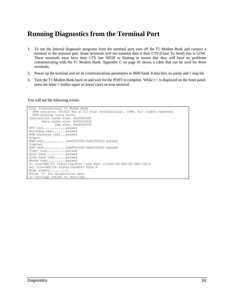
Diagnostics 59
Running Diagnostics from the Terminal Port
1. To run the internal diagnostic programs from the terminal port, turn off the T1 Modem Bank and connect aterminal to the terminal port. Some terminals will not transmit data if their CTS (Clear To Send) line is LOW.These terminals must have their CTS line HIGH or floating to ensure that they will have no problemscommunicating with the T1 Modem Bank. Appendix C on page 91 shows a cable that can be used for theseterminals.
2. Power up the terminal and set its communications parameters to 9600 baud, 8 data bits, no parity and 1 stop bit.
3. Turn the T1 Modem Bank back on and wait for the POST to complete. While P1 is displayed on the front panel,press the letter V (either upper or lower case) on your terminal.
You will see the following screen:
Digi International T1 Modem Bank ROM revision: 0x1400 Rev X [C] Digi International, 1996. All rights reserved ROM startup (cold boot)Instruction cache size: 0x00001000 Data cache size: 0x00000800 RAM size: 0x00400000CPU test............passedWatchdog test.......passedROM checksum test...passedSimpleRAM test............0xA0001000-0xA03F0010 passedComplexRAM test............0xA0001000-0xA0002000 passedTimer test..........passedSync test...........passedLine Card test…………….passedModem test……………………..passedT1 line=AMI/D4 Signaling=AT&T Long Haul Jitter=IN EGL=26 LBO=-22.5D&I Line=AMI/D4 Signaling=AT&T EQ=0.6Node number.........1Press '?' for diagnostics menuor carriage return to download
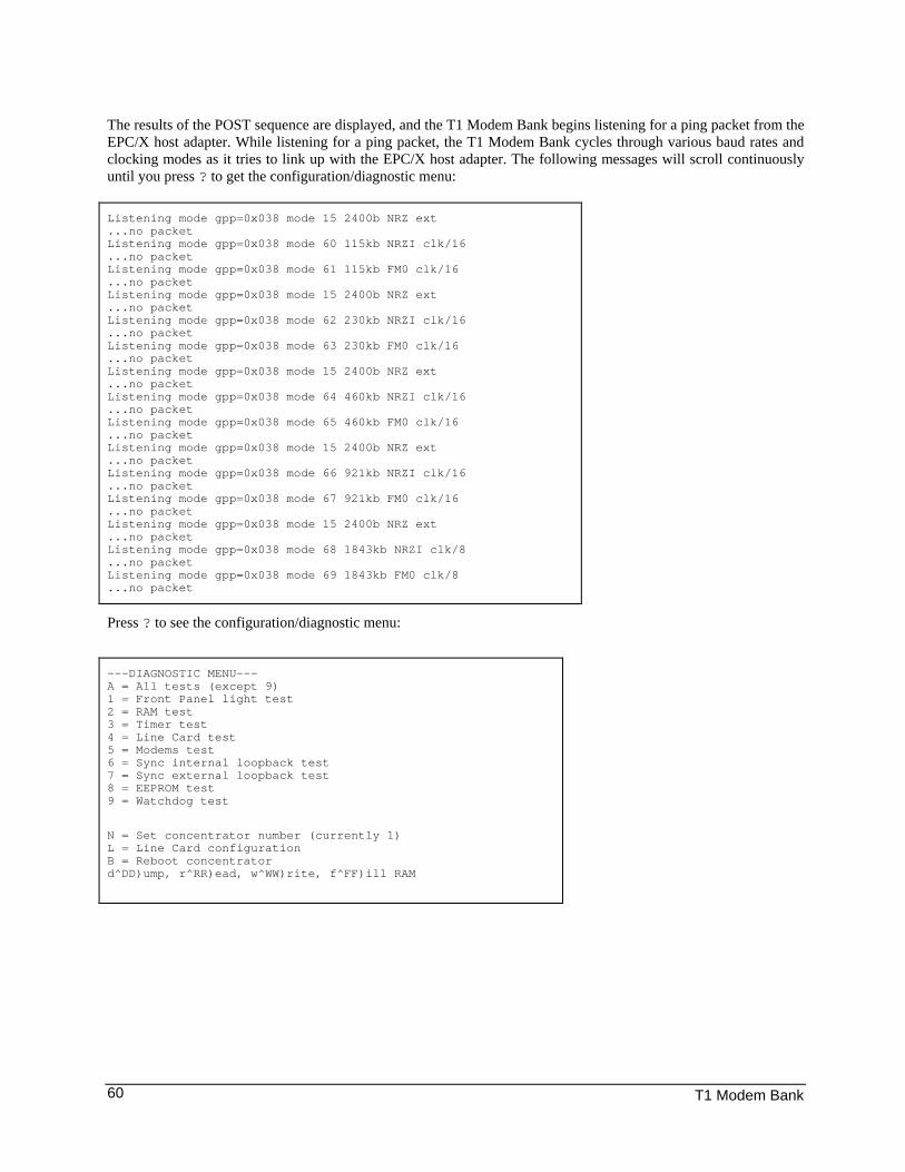
T1 Modem Bank60
The results of the POST sequence are displayed, and the T1 Modem Bank begins listening for a ping packet from theEPC/X host adapter. While listening for a ping packet, the T1 Modem Bank cycles through various baud rates andclocking modes as it tries to link up with the EPC/X host adapter. The following messages will scroll continuouslyuntil you press ? to get the configuration/diagnostic menu:
Listening mode gpp=0x038 mode 15 2400b NRZ ext...no packetListening mode gpp=0x038 mode 60 115kb NRZI clk/16...no packetListening mode gpp=0x038 mode 61 115kb FM0 clk/16...no packetListening mode gpp=0x038 mode 15 2400b NRZ ext...no packetListening mode gpp=0x038 mode 62 230kb NRZI clk/16...no packetListening mode gpp=0x038 mode 63 230kb FM0 clk/16...no packetListening mode gpp=0x038 mode 15 2400b NRZ ext...no packetListening mode gpp=0x038 mode 64 460kb NRZI clk/16...no packetListening mode gpp=0x038 mode 65 460kb FM0 clk/16...no packetListening mode gpp=0x038 mode 15 2400b NRZ ext...no packetListening mode gpp=0x038 mode 66 921kb NRZI clk/16...no packetListening mode gpp=0x038 mode 67 921kb FM0 clk/16...no packetListening mode gpp=0x038 mode 15 2400b NRZ ext...no packetListening mode gpp=0x038 mode 68 1843kb NRZI clk/8...no packetListening mode gpp=0x038 mode 69 1843kb FM0 clk/8...no packet
Press ? to see the configuration/diagnostic menu:
---DIAGNOSTIC MENU---A = All tests (except 9)1 = Front Panel light test2 = RAM test3 = Timer test4 = Line Card test5 = Modems test6 = Sync internal loopback test7 = Sync external loopback test8 = EEPROM test9 = Watchdog test
N = Set concentrator number (currently 1)L = Line Card configurationB = Reboot concentratord^DD)ump, r^RR)ead, w^WW)rite, f^FF)ill RAM

Diagnostics 61
To run individual tests, enter the test number (1-9). To run all tests (except number 9), enter A.
Tests run continuously. To stop a test, press any key during execution of the test. The current pass of the test will becompleted, and control will be returned to the terminal.
Pressing N allows you to change the T1 Modem Bank’s node number.
Pressing L allows you to change the line card configuration.
Pressing B reboots the T1 Modem Bank (similar to a power-on reset, but the diagnostic port remains active).

T1 Modem Bank62
Diagnostic Test Descriptions
Test 1: Front Panel Test
This test activates the ten LED indicators and the two 7-segment displays in four different patterns at 1-secondintervals: the first pattern lights the RD, CTS, DCD, RI and IFC LEDs plus the horizontal elements of both 7-segment displays and the decimal point of the second 7-segment display; the second pattern lights all LEDs anddisplay segments; the third pattern lights the TD, RTS, DSR, DTR and OFC LEDs plus the vertical elements of both7-segment displays and the decimal point of the first 7-segment display; the fourth pattern turns all LEDs and 7-segment displays off. The cycle then repeats. Since the indicators are write only, the operator must visually verifysuccess (or failure) of this test.
To begin the test in front panel mode, press the left push-button while the number 1 is displayed in the 7-segmentLED display. While the test is running, the 7-segment display shows the pass count. The test will be repeated untilthe left push-button is pressed. At this point, P1 will be displayed. Press the left push-button again to restart the testor the right push-button to advance to Test 2.
When run from a terminal, the test repeats until a key is pressed.
Test 2: RAM Test
The RAM test performs various walking bit and high bit tests.
RAM tests intermix cached & uncached RAM accesses.
To begin the test in front panel mode, press the left push-button while the number 2 is displayed in the 7-segmentLED display. While the test is running, the 7-segment display shows the pass count. Errors are counted on the tenLEDs, and the test is repeated until the left push-button is pressed. At this point, either P2 (pass) or F2 (fail) will bedisplayed. Press the left push-button again to restart the test or the right push-button to advance to Test 3.
When run from a terminal, the test repeats until a key is pressed.
One complete cycle of this test takes about 9 minutes.
Test 3: Timer Test
The timer test runs the internal timer and verifies that the timer can interrupt the CPU.
To begin the test in front panel mode, press the left push-button while the number 3 is displayed in the 7-segmentLED display.
When run from the front panel, the pass number is shown on the 7-segment display. Errors are counted on the tenLEDs, and the test is repeated until the left push-button is pressed. The 7-segment display will then show P3 or F3 toindicate pass or fail status.
When run from a terminal, the test repeats until a key is pressed.
Diagnostics 63
Test 4: Line Card Test
The line card test checks to make sure a line card is installed and working.
To begin the test in front panel mode, press the left push-button while the number 4 is displayed in the 7-segmentLED display.
When run from the front panel, the pass number is shown on the 7-segment display. Errors are counted on the tenLEDs, and the test is repeated until the left push-button is pressed. The 7-segment display will then show P4 or F4 toindicate pass or fail status.
When run from a terminal, the test repeats until a key is pressed.
Test 5: Modem Test
The modem test checks to make sure a modem card is installed, and all installed cards are working.
To begin the test in front panel mode, press the left push-button while the number 5 is displayed in the 7-segmentLED display.
When run from the front panel, the pass number is shown on the 7-segment display. Errors are counted on the tenLEDs, and the test is repeated until the left push-button is pressed. The 7-segment display will then show P5 or F5 toindicate pass or fail status.
When run from a terminal, the test repeats until a key is pressed.
Test 6: Sync Internal Loopback TestThis test places the high-speed synchronous channel in internal loopback mode. No loopback plug is required to runthe test. The internal loopback test checks the 4-wire transmission modes 1, 2 and 60-69. (See Appendix B,beginning on page 89, for a list of the modes).
Using Display Panel
While 6 is shown on the 7-segment LED display, press the left push-button to begin the test. This test runs in internalmode and checks the port in all 12 self-clocking modes (modes 1, 2 and 60-69) of synchronous transmission. All 2568-bit character values (00h-FFh) are sent in each mode. Errors are counted on the ten LEDs, and the test is repeateduntil the left push-button is pressed again. At this point, either P6 (pass) or F6 (fail) will be displayed. Pressing theleft push-button again restarts the test; pressing the right push-button advances to Test 7.
Using Terminal
When running this test from a terminal, you are first asked for the transmission mode (0-74). Enter the mode numberyou wish to test, or press <Enter> to test all modes. (Note that only modes 1, 2 and 60-69 are checked by this test.See Appendix B, beginning on page 89, for a list of the modes). Next, you are asked for the data to send (00h-FFh).Enter the hexadecimal value to send, or press <Enter> to use all 8-bit values.

T1 Modem Bank64
Test 7: Sync External Loopback TestThis test places the high-speed synchronous channel in external loopback mode. In video mode, this test can be runwith or without an external loopback cable. The external loopback test checks the internally clocked and self clockedtransmission modes (0-2, 6-14, 27-29 and 60-74). (See Appendix B, beginning on page 89, for a list of the modes).
Using Display Panel
While 7 is shown on the 7-segment LED display, press the left push-button to begin the test. This test runs inexternal mode and checks the port in all 12 self-clocking and internally clocked modes (0-2, 6-14, 27-29 and 60-74)of synchronous transmission. All 256 8-bit character values (00h-FFh) are sent in each mode. Errors are counted onthe ten LEDs, and the test is repeated until the left push-button is pressed again. At this point, either P7 (pass) or F7(fail) will be displayed. Pressing the left push-button again restarts the test; pressing the right push-button advancesto Test 8.
Test 8: EEPROM Test
This test generates a checksum of the EPROM contents and compares it with the checksum stored in the EEPROM.If the checksums match, the test passes. This test does not write to the EEPROM. (EEPROM write operations occuronly when a new node number is set). To begin this test in display panel mode, press the left push-button while 8 isdisplayed. Errors are counted on the ten LEDs, and the test is repeated until the left push-button is pressed again. Atthis point, either P8 (pass) or F8 (fail) will be displayed. Pressing the left push-button again restarts the test; pressingthe right push-button advances to Test 9.
Test 9: Watchdog Test
This test checks out the watchdog timer. This is a hardware feature that is used to ensure system reliability. When thewatchdog timer is loaded and enabled, the timer begins counting down. It is up to the system to keep reloading thetimer to prevent it from expiring. Normal test execution allows the timer to expire, then the test is repeated. The testfails if the timer has not expired after 1 second. To begin this test in display panel mode, press the left push-buttonwhile 9 is displayed. Errors are counted on the ten LEDs, and the test is repeated until the left push-button is pressedagain. At this point, either P9 (pass) or F9 (fail) will be displayed. Pressing the left push-button again restarts thetest; pressing the right push-button advances (wraps around) to the node number.

Component Removal and Installation 65
Component Removal and Installation
This section provides replacement instructions for various components. The line card, modem card, power supply,fan assembly, and fuse may be replaced by any on-site personnel of average skill. However, the ribbon cable, syncand terminal cable, and power inlet filter must be replaced at the factory.
Table 6 lists the various components that may need to be replaced, the required skill level, and where more detail isprovided.
Table 6 Component Level Troubleshooting
Component Skill LevelRequired for
Field Installation
Reference
Line Card Operator Line Card Removal and Replacement on page 66
Modem Card Operator Modem Card Removal and Installation/Replacement on page 68
Power Supply Operator Power Supply Removal on page 73
Power Supply Installation/Replacement on page 8
Fan Assembly Operator Fan Assembly Removal and Replacement on page 75
Fuse Operator Fuse Replacement on page 76

T1 Modem Bank66
Line Card Removal and Replacement
These instructions are provided in the event that the line card needs to be replaced in the field due to equipmentmalfunction. If the line card is malfunctioning, a message number E6 will flash in the display panel window or theboot will not proceed past the D0 state.
The T1 Modem Bank must be powered down before the line card is removed and replaced sincethe card does not have hot swap capabilities. Use the OFF/ON switch in the rear of the chassis.The PWR light will be unlit when the unit is turned off.
Figure 22 Line Card
3:5
7
Wear a grounding strap during this procedure to prevent electrical discharge.

Component Removal and Installation 67
The line card is located on the left as you face the front of the chassis. It is accessed from the front of the chassis. Apower indicator LED and a T1 jack are part of the line card faceplate. Follow this procedure to replace the line card:
1. Label, then remove the T1 line.
2. There are two captive fasteners that secure the line card to the chassis. To remove the malfunctioning line card,use a flathead screwdriver to loosen the captive fasteners on the malfunctioning line card. Pull the ejector levers,then slide the malfunctioning line card out of the chassis.
3. To install the replacement line card in the slot, turn the card so the card edge faces the back plane, and the LEDand RJ48 connectors face outward, toward the front of the chassis. The slot in the chassis contains a card guide;the card should be inserted so the RFI fingers are on the left of the card guide. Slide the new card into the slotand push in firmly until the card seats with the back plane receptacle.
4. Finger-tighten the two captive fasteners on the line card. Each fastener must be properly aligned; it could bestripped if not correctly threaded into the receptacle. To better secure the line card, tighten the two captivefasteners using the screwdriver.

T1 Modem Bank68
Modem Card Removal and Installation/Replacement
Modem Card Removal
Modem cards can be “hot swapped”, meaning that no system reset is needed after a modem card is pulled out andreplaced with another modem card. This does not mean that modem boards should be moved from slot to slotwithout cause, since the motherboard senses and stores information regarding a modem board’s correct location.
• Do not remove a modem card for any reason when the activity LEDs labeledONL1-ONL6 are lit. These LEDs indicate the card is in use or “off-hook”.
• Wear a grounding strap during this procedure to prevent electrical discharge.
• The T1 Modem Bank will “busy out” unavailable lines if fewer than four modemcards are installed in the card cage.
• The maximum number of modem cards that can be installed is four. The faceplatenext to the line card is blank because a modem card can not be installed in thislocation. Blank faceplates can also be installed over any of the four possiblemodem card locations which do not contain modem cards.

Component Removal and Installation 69
Figure 23 Modem Card

T1 Modem Bank70
Modem cards are located on the front of the chassis between the line card (labeled T1 and PWR) and the sync andterminal connections (labeled HOST IN, HOST OUT and TERMINAL). Six on-line indicators and one powerindicator are found on the modem card faceplate. Refer to Figure 1 on page 1 for an overall view of theT1 ModemBank.
Follow this procedure to replace a modem card:
1. Determine which modem card needs to be replaced. This will be indicated by running POST, usingQuickManager, or observing the display panel window after the FEP/OS is loaded. There are two types ofmodem cards, and they can be interchanged in any way you want in your system. Table 7 illustrates the revisionnumbers and the differences between the types of modem cards.
Table 7 Types of Modem Cards
Modem Revision Description
0 V.34 compliant modem. Connection rates as high as 28.8kbps.No new modem flash upgrades.
1 V.34 compliant modem. Connection rates as high as 33.6kbps.Modem flash upgrades are allowable when they are available.
QuickManager will allow you to identify the revision of each modem card in your system. Figure 24 is an examplescreen showing that modem card 1 in this particular system has a revision of 0.

Component Removal and Installation 71
Figure 24 Quick Manager Modem Revision Screen
2. There are two captive fasteners that secure the modem card to the chassis. To remove the modem card, use aflathead screwdriver to loosen the captive fasteners on the malfunctioning modem card. Pull the ejector levers,then slide the malfunctioning modem card out of the chassis.
Modem Card Installation/Replacement
This section describes how to install an additional modem card or to replace a modem card that has been removed.Modem cards can be “hot swapped”, meaning that no system reset is needed after a modem card is pulled out and/orinstalled. This does not mean that modem boards should be moved from slot to slot without cause, since themotherboard senses and stores information regarding a modem board’s correct location.
Wear a grounding strap during this procedure to prevent electrical discharge.

T1 Modem Bank72
Perform the following steps to install a modem card:
1. Before installing an additional modem card into an empty slot, you must remove the faceplate covering the slot.Loosen the captive screws from the faceplate using a flathead screwdriver and lift off the faceplate.
2. To install the modem card in an empty modem slot, turn the modem card so the card edge faces the back planeand the LEDs face outward, toward the front of the chassis. The slot in the chassis contains a card guide; RFIfingers on the card should be on the left side of the card guide. Slide the modem card into the slot and pushfirmly until the card seats with the back plane receptacle.
3. Finger tighten the two captive fasteners on the modem card. Note that each fastener must be properly aligned;the fasteners could be stripped if they are not correctly threaded into the receptacle. To better secure the modemcard, tighten the two captive fasteners using the flathead screwdriver.
4. After installation, the power LED (marked PWR) on the modem card will be lit.

Component Removal and Installation 73
Power Supply Removal
There are two ways to check a power supply failure:
• Use QuickManager
• Check the LED on the power supply’s printed circuit board. An unlit LED indicates that the power supply hasfailed.
• Wear a grounding strap while performing the following procedure to prevent electricaldischarge.
• Avoid touching the fan during the following procedure since the fan blade could causeharm.
1. If dual power supplies are installed in the unit, determine which power supply is malfunctioning. Because dualpower supplies feature a load redundant hot swap scheme, the malfunctioning power supply can be removedwithout powering down the unit.
If the T1 Modem Bank has only one power supply installed, use the ON/OFF switch at the backof the T1 Modem Bank to power-down before removing the power supply.
2. Loosen the two captive screws on the display panel faceplate; carefully pull down the hinged display panelfaceplate to access the power supply (or supplies).
When handling the power supply printed circuit board, do not touch the edge connector thatconnects to the distribution board because damage to the board may result.
3. Pull out the malfunctioning power supply from the chassis.
4. See “T1 Modem Bank Power Supply Installation/Replacement” on page 8 for instructions oninstalling/replacing a power supply.

T1 Modem Bank74
Figure 25 Power Supply

Component Removal and Installation 75
Fan Assembly Removal and Replacement
If the T1 Modem Bank overheats or exceeds its operating range, the fan is probably malfunctioning. If this is thecase, follow the procedure below.
Wear a grounding strap while performing these procedures to prevent electrical discharge.
1. Loosen the two captive screws on the display panel faceplate; carefully pull down the hinged display panelfaceplate to access the fan assembly.
2. The fan assembly consists of a fan mounted on a card guide. Look into the chassis and observe the fan assemblywhile the power is on. An unlit LED on the fan assembly indicates the fan is malfunctioning or the fuse isblown.
3. Turn off the T1 Modem Bank using the power switch on the rear of the unit.
4. Slide the malfunctioning fan assembly out of the chassis.
5. Slide the replacement fan assembly into the chassis.
• Make sure the fan assembly is installed so that the airflow will exit the chassis.
• Make sure the fan assembly is seated with the connector on the AC distribution board.
See Figure 26.
6. Push up the hinged display panel faceplate and tighten the two captive screws.
Figure 26 Fan Assembly
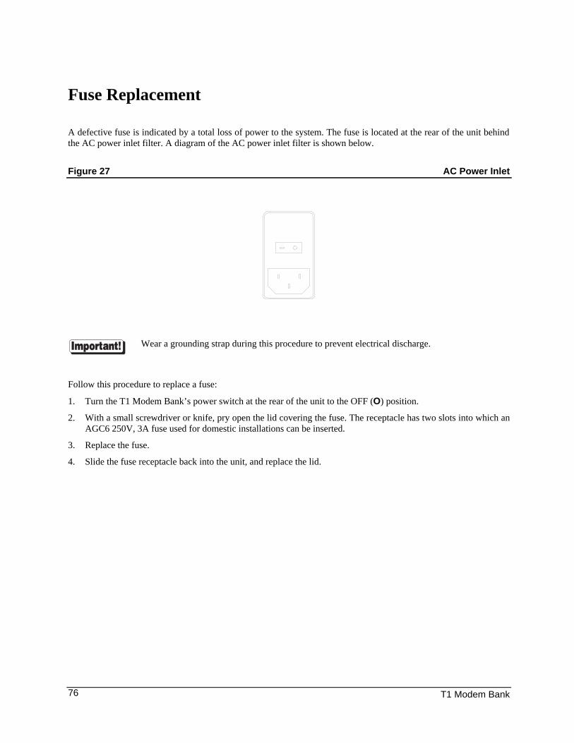
T1 Modem Bank76
Fuse Replacement
A defective fuse is indicated by a total loss of power to the system. The fuse is located at the rear of the unit behindthe AC power inlet filter. A diagram of the AC power inlet filter is shown below.
Figure 27 AC Power Inlet
Wear a grounding strap during this procedure to prevent electrical discharge.
Follow this procedure to replace a fuse:
1. Turn the T1 Modem Bank’s power switch at the rear of the unit to the OFF (O) position.
2. With a small screwdriver or knife, pry open the lid covering the fuse. The receptacle has two slots into which anAGC6 250V, 3A fuse used for domestic installations can be inserted.
3. Replace the fuse.
4. Slide the fuse receptacle back into the unit, and replace the lid.
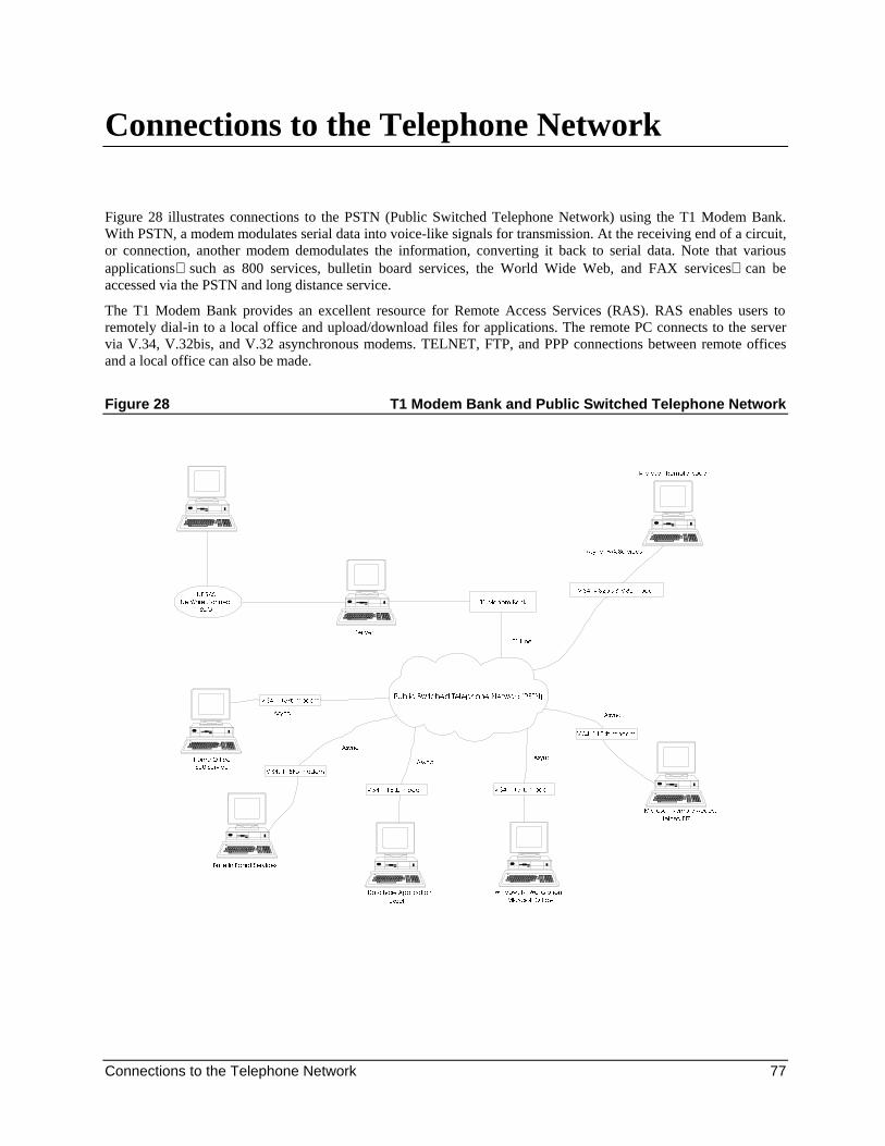
Connections to the Telephone Network 77
Connections to the Telephone Network
Figure 28 illustrates connections to the PSTN (Public Switched Telephone Network) using the T1 Modem Bank.With PSTN, a modem modulates serial data into voice-like signals for transmission. At the receiving end of a circuit,or connection, another modem demodulates the information, converting it back to serial data. Note that variousapplicationssuch as 800 services, bulletin board services, the World Wide Web, and FAX servicescan beaccessed via the PSTN and long distance service.
The T1 Modem Bank provides an excellent resource for Remote Access Services (RAS). RAS enables users toremotely dial-in to a local office and upload/download files for applications. The remote PC connects to the servervia V.34, V.32bis, and V.32 asynchronous modems. TELNET, FTP, and PPP connections between remote officesand a local office can also be made.
Figure 28 T1 Modem Bank and Public Switched Telephone Network
7 0RGHP %DQN
0LFURVRIW 5HPRWH 1RGH
3XEOLF 6ZLWFKHG 7HOHSKRQH 1HWZRUN 3671
7 /LQH
$V\QF )$; 6HUYLFHV
9 9ELV 9 PRGHP
$V\QF
$V\QF
9 NE PRGHP
9 NE PRGHP
9 NE PRGHP9 NE PRGHP
9 NE PRGHP
$V\QF
$V\QF
$V\QF
0LFURVRIW 5HPRWH $FFHVV
:LQGRZV 17 :RUNVWDWLRQ'DWD %DVH $SSOLFDWLRQ
0LFURVRIW 2IILFH
7HOQHW )73
%XOOHWLQ %RDUG 6HUYLFHV
+RPH 2IILFH
6HUYLFH
6HUYHU
([FHO
17 5$6
1HW:DUH &RQQHFW
6&2

T1 Modem Bank78
Alarms on a T1 Span
Alarm Reason for Alarm Result of Alarm
RedAlarm
The T1 Modem Bank is not receiving a valid signalfrom the T1 Line.
The T1 Modem Bank sends a “YellowAlarm” down the T1 line, and it will notaccept calls or dial out.
YellowAlarm
The Central Office was in a Red Alarm state (i.e., itcan’t hear you). The alarm goes awayapproximately 15 seconds after the Red Alarmclears itself.
The T1 Modem Bank can not acceptcalls or dial out on the T1 line.
BlueAlarm
Keep-alive signal from the T1 Line. Remote CSU isgenerating it, or an improper supervision mode(signaling) was chosen.
The T1 Modem Bank can not acceptcalls or dial out on the T1 line.
T1 Modem Bank Interaction
Interaction takes place between the PSTN, the T1 Modem Bank, and the PC containing the EPC/X host adapter.
Figure 29 shows the major components of the T1 Modem Bank and the connections between them. An EPC synclink interconnects an EPC/X host adapter and an EPC concentrator. (The EPC/X host adapter plugs into a slot in acomputer’s interface bus.) Data is then transmitted via V.34 modems to a T1 Line interface, which in turn sends thedata to the T1 line. This occurs using a T1 line in either CSU mode or non-CSU DSX-1 mode.
• CSU mode can transmit data on a T1 line over distances from 0 to 6,000 feet, without a repeater, using 22AWG twisted-pair cable.
• Non-CSU DSX-1 mode transmits to a PBX only over short distances, up to 655 feet, with receive jitterattenuation.
Figure 29 Functional Block Diagram of the T1 Modem Bank

Physical Specifications 79
Physical Specifications
T1 Modem Bank Power Cord Specifications
The chassis has a 3-wire power cord. The free end of the 3-wire power cord connects to the 110 VAC (domestic)power source and protective ground. NEMA plug type 5/15P is used for US installations.
The North American cordset is rated 15A/125V, and is UL/CSA approved.
A T1 Modem Bank sold in North America is shipped with a standard power cord. Units soldoutside of North America are shipped without a power cord. If the power cord needs to bereplaced, or if you need to purchase an original power cord, use only a cord that meets thefollowing specifications:
Type: SJT or SVT flexible power cord, compatible with an IEC320 appliance inlet.Safety Approvals:
The cord must bear the mark of the agency in your country (such as UL, CSA, VDE,SEMKO, and so on).
Temperature Rating:75°C minimum
Voltage Rating:125 Volts minimum (North America)
Current Rating:15 Amps maximum
Conductor Size:3 x 18 AWG or 3 x 0.75 mm, or larger
For power cord selection in Germany, use only a H05VV-F, <HAR>, VDE, PVC, 3 x 0.75mmpower cord.
Für gebrauch in Deutschland muß ein Netzkabel des typs H05VV-F, <HAR>, größe, 3 x0.75mm verwendet werden.

T1 Modem Bank80
T1 Modem Bank Environmental Requirements
The T1 Modem Bank meets all functional requirements in this manual when operating in the environment listedbelow:
Ambient Temperature 0° C to 40° C
Relative Humidity 5% to 90%, non-condensing
Altitude 0 to 12,000 feet
T1 Modem Bank Rack Specifications
The specifications listed below apply to both standalone units and rack-mounted units.
Depth 13.0132inches
Height 6.930 inches
Weight 32 lb. fully loaded
Width 17.048 inches
Standalone Unit Specifications
Width 17.048 inches
Rack Specifications
The T1 Modem Bank rack systems are enclosed in either a 19” or 24” rack.
4U 19 Inch Rack System
Width 19.000 inches (with mounting brackets for rack installations)
4U 24 Inch Rack System
Width 24.000 inches (with mounting brackets for rack installations)

Physical Specifications 81
Daisy Chain Cables
Daisy Chain cables have the following attributes:
• Twisted pair, overall shield, 28 AWG
• Capacitance 15.5 ±3 pF/ft.
• Impedance 100 Ω/ft.
• Belden 8-wire (4 twisted pair) #9806, or Belden 4-wire (2 twisted pair) #9804 HD-15 subminiature connectors, 1 male (AMP #748364-1 or equivalent; contacts: size 22 male AMP #748333-5 (or equivalent), and 1 female (AMP #748565-1 or equivalent; contacts: size 22 female AMP #748610-2 (or equivalent)
• Digi part number 62110018 (18”)
Terminator Plug
Terminal plugs have the following attributes:
• HD-15 subminiature male plug (AMP #748364-1) or equivalent
• Contacts: size 22 male (AMP #748333-5 or equivalent) with the following pairs of pins wired together:1-6, 2-7, 3-15, 4-9, 5-10, 8-14
• Digi part number 60000388
T1 Loop Back Plug
• RJ45 8P/8C hone plug
• Pins wired together: 1-4, 2-5
• Digi part number 63000001-01
T1 Modem Bank82
T1 Modem Bank Certification
The T1 Modem Bank is certified to meet the following electromagnetic emissions and safety standards:
Emissions:
USA: FCC Part 15, Subpart J, Class A
Canada: CSA C108.8-M83, Class A
Cispr 22, Class A EN55022
Safety:
USA: UL 1950
Canada: C22.2 No. 950
Telecom:
USA: FCC part 68
Canada: ICCS 003

Glossary 83
Glossary
AMI (Alternate Mark Inversion) a line coding method for T1 spans.
bandwidth the difference between the highest and lowest frequencies in a given range; the maximum data-carrying capacity of a circuit. (Greater bandwidth indicates higher speed data-transfer.)
B8ZS (Binary 8-Zero Suppression) a line coding method for T1 spans
channel an increment of bandwidth provided by the WAN.
channel bank a voice time division multiplexer.
CSU (Channel Service Unit) the interface to the T1 line that terminates the local loop.
Drop-and-insert a service feature where some number of DS0s are passed through the T1 Modem Bank to othertelephone equipment, usually a PBX. The remaining DS0s terminate at the T1 Modem Bank.
DS-0 (Digital Signal Level 0) a 64K bps channel, the world-wide standard speed for PCM digitized voicechannels.
DS-1 (Digital Signal Level 1) in North America, a 1.544M bps data stream composed of 24 DS0 channels. A DS1is provided on T1 transport facilities.
DSX-1 (Digital Signal Cross Connect, Level 1) part of the DS-1 specification.
DTMF (Dual Tone Multi Frequency)touch-tone dialing
E&M Signaling leads on a voice tie line; known as “Ear and Mouth.” Types I and II are most common in the US.
EPC/X (Enhanced Performance Concentrator)
ESF (Extended Super Frame) ESF is based on ANSI T1.403 or AT&T Pub 54016.
flow control a mechanism for limiting the amount or rate of data sent by a transmitting entity to avoid congestionin the network or the receiving device.
ground start T1 supervision and signaling method
ISO (International Standards Organization) a voluntary, independent organization chartered to define internationalstandards for communications of all types.
ISO model (More completely, the ISO model for Open Systems Interconnection) This is the model of computercommunications that has seven layers. The ISO model describes the ISO OSI communications architecture. ISO communications standards fit into several places in this model.
jitter short term variations in the rate at which data arrives on the T1 span. Jitter is removed by means of a “jitterattenuator” which is present in the T1 Modem Bank.
LAN (Local Area Network) a communications architecture that passes information between multiple systemsover relatively short distances at high speeds
line the physical interface to the WAN.
LBO (Line Build Out) Insertion of loss in a short transmission line to make it act like a longer line
Loop-Start T1 supervision and signaling method
modem (Modulator-demodulator) a device for modulating a carrier with a data stream ready for transmission anddemodulating or extracting a data signal from a received signal.

T1 Modem Bank84
network a collection of links, nodes, and computers that provide connections between two or more defined pointsto facilitate telecommunication between them.
off-hook the modem is in use, and the activity light is on.
PCM (Pulse Code Modulation) the standard digital voice format, at 64K bps;
POP (Point-of-Presence) the point within a local TELCO where the subscribers’ circuits for leased-line or longdistance dialup circuits are terminated.
PPP (Point-to-point protocol) a communication link in which two stations are directly connected. PPP allows forTCP/IP connections over serial lines and serial devices such as modems.
Private or leased lines refer to a permanent circuit between endpoints over which data is transmitted. Private orleased circuits are available from providers of WAN digital communications. T1 lines can be supplied by theprovider to include private or leased circuits and others such as switched lines.
Protocol a set of rules or standards designed to enable computers to connect with one another and exchangeinformation with as few errors as possible.
PSTN (Public Switched Telephone Network)
Robbed bit signaling a bit in the data stream used for signaling
switched line a single-circuit line connection between two points on a switched network. This is usually aconnection made as a result of dialing via the phone system, as opposed to a permanent leased line.
TCP/IP (Transmission Control Protocol/Internet Protocol) a set of network services that provides interoperabilitybetween heterogeneous systems. The TCP portion is responsible for providing reliable and recoverablecommunications between two end points. The IP portion sets up the routing used by TCP to transmit.
TELCOS TELephone COmpanies
T1 a digital transmission method for multiplexing multiple voice and/or data channels over a system of copperwire cables with amplifiers or regenerators that reinforce the digital signal at intervals of about one mile. T1 offers atwo-way connection at 1,544,000 bits per second. One T1 line carries a DS1 circuit, the equivalent of 24 portconnections running at 64K bps. Depending upon the provisioning by the carrier, both leased channels and switchedchannels may be combined. Point-to-point dedicated T1 lines provide only permanent circuits. Switched T1 linescommonly use in-band signaling for call management, resulting in switched 56K bps channels.
UART (Universal Asynchronous Receiver/Transmitter) a device that performs asynchronous communicationfunctions by converting parallel digital output from a DTE device into serial bit transmission and vice versa.
virtual circuit a communications link that appears to be a direct connection between sender and receiver,although the link can physically involve routing between a more circuitous path.
Wide-Area Network (WAN) a network composed of systems that are relatively far apart, meaning that the areais usually gauged in hundreds of miles. A WAN may also encompass a series of LANs connected over a wide area.
In this manual, WAN refers to a network consisting of lines provided by telephone companies.
wink start in placing a call, the T1 Modem Bank goes off-hook, then waits for a wink acknowledgment beforedialing.

Appendix A 85
Appendix A — Memory Conflicts
Contention for Memory AddressesMany intelligent peripheral devices require a block of vacant memory addresses on the host computer’s bus for theirown use. These memory addresses may be used to access a dual-ported RAM on the peripheral device to facilitatethe transfer of large volumes of data between the host and the peripheral (memory-to-memory transfers are muchfaster than I/O bus transfers), or they may point to a ROM BIOS (a firmware program used by the host computer tocontrol the peripheral device). In either case, the host computer sees this memory as its own, and can use the samehigh-speed memory-referencing commands that it uses with its internal memory.
Figure 30 on the following page shows a map of the first megabyte of a host system’s memory bus. The shaded areasrepresent the computer’s internal RAM (nearly always 640K, but can often be reduced to 512K—there is alsousually more RAM above the 1 Meg boundary). The area between the RAM and the 1 Meg boundary is used for thehost system’s BIOS, option ROMs and peripheral memory. The memory map shows the locations typically used bysome of the most common peripheral devices.
The memory map on the following page shows typical memory usage. To be certain of what ar-eas are available in your system, you will need to consult the documentation for your computerand peripheral devices.
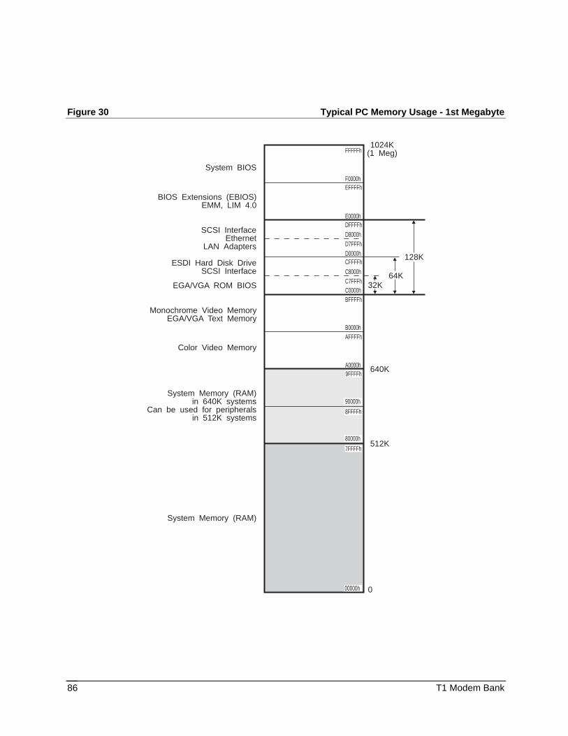
T1 Modem Bank86
Figure 30 Typical PC Memory Usage - 1st Megabyte
A0000h
AFFFFhB0000h
BFFFFhC0000h
C8000h
D8000h
CFFFFh
C7FFFh
D7FFFhD0000h
DFFFFhE0000h
EFFFFhF0000h
FFFFFh
ESDI Hard Disk DriveSCSI Interface
EGA/VGA ROM BIOS
System BIOS
BIOS Extensions (EBIOS)EMM, LIM 4.0
Color Video Memory
System Memory (RAM)
System Memory (RAM)in 640K systems
Can be used for peripheralsin 512K systems
Monochrome Video MemoryEGA/VGA Text Memory
512K
640K
1024K(1 Meg)
000000h
80000h
90000h
7FFFFh
8FFFFh
9FFFFh
SCSI InterfaceEthernet
LAN Adapters
32K64K
128K

Appendix A 87
ISA Host Adapters
The Digi ISA EPC/X host adapter has 1 megabyte of on-board dual-ported RAM which is accessed through a 32K“window”, which can be mapped into any 32K region in the computer’s memory address space (32K byteboundaries end with either 0000h or 8000h). The dual-ported RAM can also be mapped in its entirety into the hostcomputer’s memory address space on any 1 megabyte boundary below 16MB—this option will be supported insome future device driver software releases.
Current Digi device drivers support sixteen preconfigured 32K address ranges for ISA host adapters, beginning at80000h, 88000h, 90000h, 98000h, A0000h, A8000h, B0000h, C8000h, C0000h, C8000h, D0000h, D8000h,E0000h, E8000h, F0000h or F8000h. These addresses are all below the 1 megabyte boundary. In practice, only fourof these address ranges are likely to be available. The addresses E0000h-FFFFFh are typically used for the systemBIOS and BIOS extensions; the addresses A0000h-BFFFFh are used for video buffers, and the addresses 80000h-9FFFFh are between 512K and 640K, and so can only be used with host computers having no more than 512K ofbase memory (memory below 1 megabyte). Since most computers have 640K of base memory, only the addressesfrom C0000h-DFFFFh are generally usable. To complicate matters, most intelligent peripheral devices require somememory address space in this region for their ROM or shared memory. It is therefore necessary to insure that thememory address range chosen for the ISA host adapter does not conflict with the range used by any other device inyour system.
Some typical sources of contention are:
• Plug-in VGA and EGA cards, which have a ROM BIOS beginning at C0000h.
• ESDI hard disk controllers, which typically have a ROM BIOS beginning at C8000h or CC000h.
• SCSI interfaces, which have a ROM BIOS that may be located anywhere in the C0000h-DFFFFh range.
Consult the documentation for your peripheral devices to determine what (if any) memory addresses they may beoccupying on the host memory bus.
Conflicts Between 8-Bit and 16-bit Memory Devices
The ISA (Industry-Standard Architecture) bus, used in 80286 (AT compatible) and 80386 based computers, supports16-bit memory and peripherals with 16-bit dual-ported memory or ROM. By default, however, memory devices areconsidered to be 8-bit devices. 16-bit devices must declare themselves by raising a flag, so that the host knowswhether it is referencing a byte (8 bits) or a word (16 bits) of memory.
Memory addressing on the ISA bus consists of 2 phases: First the unlatched address bits (bits A17 to A23) are placedon the bus. Then the latched bits (A00 to A16) are placed on the bus. A 16-bit device must declare itself after theunlatched bits go on the bus, but before the latched bits go out. Since the unlatched bits can only resolve 128Kblocks of memory (e.g. 080000h-09FFFFh, 0A0000h-0BFFFFh, 0C0000h-0DFFFFh), the presence of any 16-bitdevice in a 128K segment causes the entire segment to be treated as 16-bit memory. Thus if an 8-bit device resides inthe same 128K block as a 16-bit device, only even-numbered bytes will be accessible, and the device will fail.
The ISA EPC/X host adapter is a 16-bit board.

T1 Modem Bank88
EISA Host Adapters
The Digi EISA EPC/X host adapter has 1 megabyte of on-board dual-ported RAM which is accessed through a 32K“window”, which can be mapped into any 32K region in the computer’s memory address space up to the 4 gigabytelimit. The EISA EPC/X configuration file provides sixteen address ranges below 1 megabyte, and sixteen addressranges in the fourth gigabyte:
Below 1 Megabyte:*80000h 88000h 90000h 98000hA0000h A8000h B0000h B8000hC0000h C8000h D0000h D8000hE0000h E8000h F0000h F8000h
Above 1 Megabyte:F0000000h F1000000h F2000000h F3000000hF4000000h F5000000h F6000000h F7000000hF8000000h F9000000h FA000000h FB000000hFC000000h FD000000h FE000000h FF000000h
* When addressed below 1 megabyte, the same constraints apply as for the ISA host adapter (see page 87).

Appendix B 89
Appendix B — Transmission Modes
The EPC/X host adapter and the T1 Modem Bank transmit synchronous data in one of 75 modes. These modes arenumbered 0 - 74, and each corresponds to a specific combination of wiring mode (4-Wire or 8-Wire), clockingmethod (internal, external or self-clocking) and baud rate. The 75 modes and their definitions are listed below:
8-Wire, Internally Clocked
Mode# Mode Baud Rate Mode# Mode Baud Rate
0 NRZ 115K 13 NRZ 921K3 NRZ 2400 14 NRZ 1229K4 NRZ 4800 27 NRZ 1843K5 NRZ 9600 28 NRZ 2458K6 NRZ 19200 29 NRZ 3686K7 NRZ 38400 70 NRZ 1843K8 NRZ 57600 71 NRZ 2458K9 NRZ 76800 72 NRZ 3686K10 NRZ 115K 73 NRZ 7373K11 NRZ 230K 74 NRZ 10M12 NRZ 460K
8-Wire Synchronous Modem (External Clock)
Mode# Mode Baud Rate Mode# Mode Baud Rate
15 NRZ 2400 35* NRZ 240016 NRZ 4800 36* NRZ 480017 NRZ 9600 37* NRZ 960018 NRZ 19200 38* NRZ 1440019 NRZ 38400 39* NRZ 1920020 NRZ 57600 40* NRZ 3840021 NRZ 76800 41* NRZ 5760022 NRZ 115K 42* NRZ 6411123 NRZ 230K 43* NRZ 7680024 NRZ 460K25 NRZ 921K26 NRZ 1229K30 NRZ 1843K31 NRZ 2458K32 NRZ 3686K33 NRZ 1440034 NRZ 115K* Modes 35-43 are for RS-232 synchronous modems; modes 15-34 are for RS-422 synchronous modems.

T1 Modem Bank90
4-Wire, Self Clocked
Mode# Mode Baud Rate Mode# Mode Baud Rate
1 NRZI 230K 64 NRZI 460K2 FM 460K 65 FM 460K60 NRZI 115K 66 NRZI 921K61 FM 115K 67 FM 921K62 NRZI 230K 68 NRZI 1843K63 FM 230K 69 FM 1843K

Appendix C 91
Appendix C — Terminal Port Cable
Some terminals will not transmit data if their CTS (Clear To Send) line is LOW. These terminals must have theirCTS line HIGH or floating to ensure that they will have no problems communicating with the T1 Modem Bank. Thecable shown in Figure 31 can be used if a terminal of this kind does not require hardware handshaking.
Figure 31 Simple Terminal Cable

T1 Modem Bank92
Appendix D — Specifications and Wiring Pin Diagrams
Line Card Connector
Figure 32 illustrates an RJ-45 plug that can be inserted into the T1 line card connector.
Figure 32 RJ-45 Plug
The following are pin assignments for the T1 line interface and the DSX-1 line interface.
Signal Pin
RxTIP 1
RxRING 2
NC 3
TxTIP 4
TxRING 5
NC 6
NC 7
NC 8
Specifications:
Cable: Standard: UL or ETL verified to Category 5 specifications.
Type: Unshielded twisted pair
Number of pairs: 2
Jacket: PVC
Conductor: 24 AWG solid copper
Diameter: .175” + .005, -.03
Color: Gray
Mfg./Model: Berk TEK/530121 (or equivalent)
Plug:
Type: Pre-loaded RJ45 male
Material: Polycarbonate
Color: Clear
Contacts: Phosphor-bronze, gold-plated .000020” minimum on contact area
Mfg./Model: AMP/557315-1 (or equivalent)
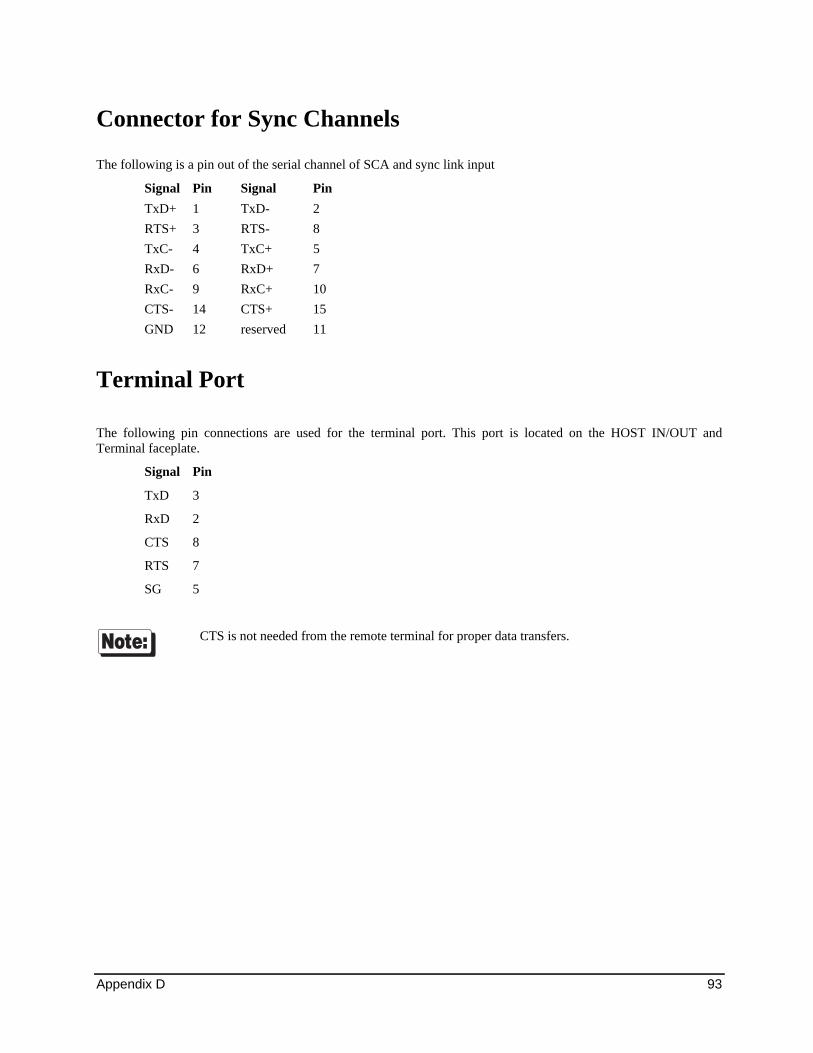
Appendix D 93
Connector for Sync Channels
The following is a pin out of the serial channel of SCA and sync link input
Signal Pin Signal Pin
TxD+ 1 TxD- 2
RTS+ 3 RTS- 8
TxC- 4 TxC+ 5
RxD- 6 RxD+ 7
RxC- 9 RxC+ 10
CTS- 14 CTS+ 15
GND 12 reserved 11
Terminal Port
The following pin connections are used for the terminal port. This port is located on the HOST IN/OUT andTerminal faceplate.
Signal Pin
TxD 3
RxD 2
CTS 8
RTS 7
SG 5
CTS is not needed from the remote terminal for proper data transfers.

T1 Modem Bank94
Appendix E — Generic T1 Modem BankWiring Modes
There are three basic wiring modes for connecting T1 Modem Bank units to an EPC/X host adapter or to each other:Eight-Wire Direct, Four-Wire Direct (also called Four-Wire Self-Clocking), and Eight-Wire Synchronous Modem(or Eight-Wire Externally Clocked).
Eight-Wire Direct Wiring
Eight-Wire Direct is the standard method for connecting T1 Modem Bank units to EPC/X host adapter synchronouslines and to other T1 Modem Bank units. It provides transmit and receive data signals plus discrete clock signals fortransmit and receive data. This permits synchronous data rates of up to 10M bps, which results in the maximum datathroughput under moderate to heavy loads. (See Table 8 on page 96 for restrictions on cable lengths). Thesynchronous cables provided with the T1 Modem Bank units are Eight-Wire Direct cables. The Eight-Wire Directcable is a twisted pair cable with a male HD-15 (high-density DB-15) connector at one end and a female HD-15 atthe other end. The cable should be shielded, and the shield must be connected to the HD-15 connector shell at bothends. See Figure 33.
Figure 33 Eight-Wire Direct Daisy Chain Cable Wiring

Appendix E 95
Four-Wire Direct Wiring
Four-Wire Direct wiring connects T1 Modem Bank units where longer synchronous cable runs are necessary. Whilenot as fast as Eight-Wire connections (the maximum data transfer rate is 1.8 megabaud1), this wiring method is moreeconomical, and is sufficient in all but the most demanding high-performance applications. This means that terminalusers should see no degradation in performance. In the Four-Wire Direct wiring mode, the clock signals are encodedwith the receive and transmit data signals, so only two twisted pairs are required. The Four-Wire Direct cable is atwisted pair cable with a male HD-15 (high-density DB-15) connector at one end and a female HD-15 at the otherend. The cable should be shielded, and the shield must be connected to the HD-15 connector shell at both ends. SeeFigure 34.
Figure 34 Four-Wire Direct Daisy Chain Cable Wiring
1 If each T1 line transmits at 1.544 Mbit/second, only one T1 Modem Bank can be connected to this line and still maintain the full data rate. SeeTable 8 on page 96 for restrictions on cable lengths.

T1 Modem Bank96
Restrictions on Daisy Chain Cable Lengths
The maximum length of a daisy chain is dependent upon the synchronous data rate. Table 8 lists the maximumcumulative daisy chain cable lengths for various baud rates. For example, to run a synchronous line at 10 megabaud,the total length of all daisy chain cables for that synchronous line may not exceed 30 feet. Thus, a single T1 ModemBank could be placed 30 feet from the EPC/X host adapter, or six T1 Modem Bank units could be spaced at 5 footintervals and still operate at 10 megabaud.
Table 8 Daisy Chain Cable Length vs. Baud Rate
Baud Rate Maximum Cable Length(24AWG Twisted Pair, 12 pF/foot)
0 - 460K 0 - 1.2M 0 - 2.5M 0 - 5M 0 - 10M
2000 feet1000 feet300 feet120 feet30 feet

Appendix E 97
Eight-Wire Synchronous Modem Wiring
Eight-Wire Synchronous Modem wiring allows T1 Modem Bank units to be installed in remote locations andconnected to the EPC/X host adapter via RS-232 or RS-422 synchronous modems.
The EPC/X host adapter and the T1 Modem Bank have been designed so that the synchronous ports can supporteither RS-422 or RS-232 line levels. To connect EPC/X host adapters and T1 Modem Banks to RS-232 synchronousmodems, use the special cables shown in Figure 35.
Note that only the negative lead for each RS-422 signal is used in this configuration. The positive lead is left“floating”.
If you are building your own cable, four 2200 pF capacitors (X7R 50V type) are required—two for the EPC/X hostadapter and two for the T1 Modem Bank. Install the capacitors between the positive and negative leads of the TxCand RxC signals on the back of the HD-15 connectors, as shown in Figure 35.
Figure 35 RS-232 Synchronous Modem Cables

T1 Modem Bank98
RS-422 synchronous modems can also be used with the EPC system. The required cables are shown in Figure 36.
Figure 36 RS-422 Synchronous Modem Cables
The RS-422 Synchronous Modem cables are twisted pair cables, each having an HD-15 (high-density DB-15)connector at one end and a DB-37 connector at the other end. The cable should be shielded, and the shield must beconnected as shown in the above diagram.

Appendix F 99
Appendix F — Modem AT Command Set
Default values of command parameters, if applicable, areindicated by an asterisk (*).
Basic AT Commands
A/ Repeat Last Command
Repeats execution of the previous command string. “A/” must not be preceded with AT, or followed bypressing <Enter>.
A Answer
Causes the modem to go off-hook and attempt to establish a connection, even in the absence of a ring.
Bn Line Modulation Options
Configures the modem to the desired communications standard setting at a particular line speed.
B0: Selects CCITT V.22 mode when the modem is at 1200 bps, and CCITT V.21 when the modem isat 300 bps.
* B1: Selects Bell 212A when the modem is at 1200 bps, and Bell 103 when the modem is at 300 bps.
B2: Selects V.23 originate mode receive 1200 bps, transmit 75 bps; answer mode receive 75 bps,transmit 1200 bps.
B3: Selects V.23 originate mode receive 75 bps, transmit 1200 bps; answer mode receive 1200 bps,transmit 75 bps.
Result Codes:
OK Returned when n = 0, 1, 2 or 3.
ERROR Returned for any other value of n.
Cn Carrier Control Option (no operation)
This command is included to provide backward compatibility with communications software that issues thiscommand.
C0: Returns ERROR.
C1: Normal transmit carrier switching.
Result Codes:
OK Returned when n = 1.
ERROR Returned for any other value of n.

T1 Modem Bank100
Dn Dial Command
Initiates the dialing sequence. The string n includes the dial modifiers and the telephone number to bedialed.
Dial Modifiers:
P: Pulse dial. Only digits 0-9 may be used in pulse dial mode.
R: Reverse dial mode. Originates call in answer mode.
S=n: Dial stored number. Dials the number stored in location n (0-3).
T Tone DTMF dial. Any digit 0-9, *, #, A, B, C, D may be dialed as a tone.
W Wait for dial tone. The modem waits for dialtone before dialing.
, Pause. Causes the modem to pause before processing the next character in the dial string.
! Flash hook. Causes the modem to go on-hook for 0.5 seconds, then go off-hook again.
@ Wait for quiet answer. Wait for five seconds of silence after dialing the number.
; Return to idle state. Modem returns to command mode after dialing a number, but does notdisconnect call.
En AT Command Echo Options
Enables or disables echo of characters from the modem to the DTE when the modem is in command mode.
E0: Echo disabled.
* E1: Echo enabled.
Result Codes:
OK Returned when n = 0 or 1.
ERROR Returned for any other value of n.
Fn Online Echo Command (no operation)
This command is included to provide backward compatibility with communications software that issues thiscommand.
F0: Returns ERROR.
F1: Online echo disabled.
Result Codes:
OK Returned when n = 1.
ERROR Returned for any other value of n.
Hn Switchhook Control
Provides control of the line relay.
H0: Causes modem to go on-hook.
H1: Causes modem to go off-hook, but does not train.
Result Codes:
OK Returned when n = 0 or 1.
ERROR Returned for any other value of n.
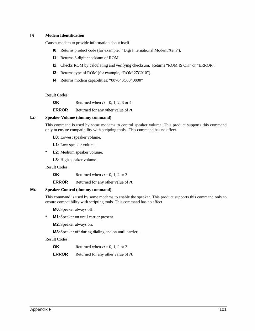
Appendix F 101
In Modem Identification
Causes modem to provide information about itself.
I0: Returns product code (for example, “Digi International Modem/Xem”).
I1: Returns 3-digit checksum of ROM.
I2: Checks ROM by calculating and verifying checksum. Returns “ROM IS OK” or “ERROR”.
I3: Returns type of ROM (for example, “ROM 27C010”).
I4: Returns modem capabilities: “007040C0040000”
Result Codes:
OK Returned when n = 0, 1, 2, 3 or 4.
ERROR Returned for any other value of n.
Ln Speaker Volume (dummy command)
This command is used by some modems to control speaker volume. This product supports this commandonly to ensure compatibility with scripting tools. This command has no effect.
L0: Lowest speaker volume.
L1: Low speaker volume.
* L2: Medium speaker volume.
L3: High speaker volume.
Result Codes:
OK Returned when n = 0, 1, 2 or 3
ERROR Returned for any other value of n.
Mn Speaker Control (dummy command)
This command is used by some modems to enable the speaker. This product supports this command only toensure compatibility with scripting tools. This command has no effect.
M0:Speaker always off.
* M1:Speaker on until carrier present.
M2:Speaker always on.
M3:Speaker off during dialing and on until carrier.
Result Codes:
OK Returned when n = 0, 1, 2 or 3
ERROR Returned for any other value of n.

T1 Modem Bank102
Nn Select Negotiate Handshake
Controls automode enable/disable.
N0: When originating or answering, handshake only at the communication rate specified by registerS37 and command Bn, with no fallback.
* N1: When originating or answering, start handshake at the communication standard specified byregister S37 and command Bn. During handshake, fallback to lower speed may occur except in\N1 mode.
Result Codes:
OK Returned when n = 0 or 1.
ERROR Returned for any other value of n.
On Go Online
Causes the modem to go to online or data mode.
O0: Returns modem to previously established rate.
O1: Begins an equalizer retrain sequence, then returns to online state.
O3-14:Forces the modem to a new rate (defined in register S62).
Result Codes:
OK Returned when n = 0, 1 or 3-14.
ERROR Returned for any other value of n.
P Enable Pulse dialing
Instructs the modem to use pulse dialing. Dialed digits will be pulse dialed until a T command or dialmodifier is received. Tone dial is the default setting.
Qn Result Code Display Option
Controls whether result codes are returned to the DTE.
* Q0: Enable result codes.
Q1: Disable result codes.
Result Codes:
OK Returned when n = 0 or 1.
ERROR Returned for any other value of n.
Sn Select S Register n
Selects a specific S register.
n=0-99
Sn=m Write to S Register n
Writes the value m to S register n.
n=0-99
m=0-255

Appendix F 103
Sn? Read S Register n
Reports the value of S register n as a 3-digit decimal number.
n=0-99
T Enable Tone dialing
Instructs the modem to use DTMF tones when dialing. Dialed digits will be tone dialed until a P commandor dial modifier is received. Tone dial is the default setting.
Vn Result Code Format
Controls whether result codes are returned to the DTE.
V0: Numeric form (0 for OK).
* V1: Verbose form (OK for OK).
Result Codes:
OK Returned when n = 0 or 1.
ERROR Returned for any other value of n.
Wn Select Extended Result Codes
Defines which result codes are to be used to identify the type of connection and protocol that resulted fromhandshaking and negotiation.
* W0:CONNECT result code reports DTE speed.
W1:CONNECT result code reports DTE speed, plus the CARRIER, COMPRESSION andPROTOCOL extended result codes.
W2:CONNECT result code reports DCE speed.
Result Codes:
OK Returned when n = 0, 1 or 2.
ERROR Returned for any other value of n.
Xn Select Result Codes/Call Progress Options
Enables the tone detection options used in the dialing process. As these functions are chosen, the modemchip set’s result codes are also affected. This command is therefore frequently used to control the modemchip set’s responses. The primary function of this control is to control the modem chip set’s call responsecapabilities.
X0: Display CONNECT or 1 for all speeds.
X1: Display connect message according to ATW and AT\V, blind dial, ignore busy signal.
X2: Display connect message according to ATW and AT\V, wait for dial tone, ignore busy signal.
X3: Display connect message according to ATW and AT\V, blind dial, check for busy signal afterdialing.
* X4: Display connect message according to ATW and AT\V, wait for dial tone, check for busy signalafter dialing.
Result Codes:
OK Returned when n = 0, 1, 2, 3 or 4.
ERROR Returned for any other value of n.

T1 Modem Bank104
Yn Dummy Command
Dummy command for compatibility.
Y0: Returns OK.
Y1: Returns OK.
Zn Recall Stored Profile
Forces the modem to go on-hook and restore the selected profile. Non-storable parameters are returned totheir factory settings.
Z0: Reset and recall user profile 0.
Z1: Reset and recall user profile 1.
Result Codes:
OK Returned when n = 0 or 1.
ERROR Returned for any other value of n.

Appendix F 105
AT& (Ampersand) Commands
&Bn Autoretrain
Defines modem action when it receives a poor signal.
&B0 : Hang up on a poor received signal.
* &B1 : Retrain on a poor received signal. Hang up if condition persists longer than the threshold setin register S7.
&B2 : Do not hang up; do not retrain (tolerate any connection).
Result Codes:
OK Returned when n = 0, 1 or 2.
ERROR Returned for any other value of n.
&Cn Data Carrier Detect Option (Async Only)
Controls how the state of the DCD or RLSD (Receive Line Signal Detect) relates to the carrier from theremote system. Always use &C1 for Sync mode.
&C0: State of carrier from remote modem is ignored. RLSD circuit is always on.
* &C1: State of carrier from remote modem is tracked. RLSD circuit reflects the state of the carrier.
Result Codes:
OK Returned when n = 0 or 1.
ERROR Returned for any other value of n.
&Dn Data Terminal Ready Option
Defines modem action when it receives a poor signal.
&D0: DTR ignored.
&D1: Go to command mode when DTR changes from on to off.
* &D2: Hang up and go to command mode when DTR changes from on to off. Auto answer isdisabled if DTR is low.
&D3: Reset when DTR changes from on to off.
Result Codes:
OK Returned when n = 0, 1, 2 or 3.
ERROR Returned for any other value of n.
&F Load Factory Settings
Loads the configuration programmed at the factory. This command replaces all command options and Sregister settings in the active configuration with the factory values stored in the nonvolatile RAM.
&F: Recall factory setting as active configuration.

T1 Modem Bank106
&Gn Guard Tone Operation
Determines which guard tone, if any, to transmit while transmitting in the high band (answer mode). Usedonly in V.22 and V.22bis mode.
* &G0: No guard tones.
&G1: 550 Hz guard tone.
&G2: 1800 Hz guard tone.
Result Codes:
OK Returned when n = 0, 1 or 2.
ERROR Returned for any other value of n.
&Jn Dummy Command for AutoSync
Dummy command for AutoSync compatibility.
&J0 : Returns OK.
&J1 : Returns OK.
&Kn Set Flow Control
Determines which guard tone, if any, to transmit while transmitting in the high band (answer mode). Usedonly in V.22 and V.22bis mode.
&K0 : Disable flow control.
&K1 : Reserved.
&K2 : Reserved.
* &K3 : Enable bi-directional hardware flow control (RTS/CTS).
&K4 : Enable bi-directional XON/XOFF flow control.
&K5 : Error.
Result Codes:
OK Returned when n = 0, 3 or 4.
ERROR Returned for any other value of n.
&Ln Dial-Up/Leased-Line Option
Selects between dial-up and leased-line operations. NOTE: Full-featured leased line operation is notavailable at this time. Please call Digi Sales for more information.
* &L0 : Dial line.
&L1 : Leased line.
Result Codes:
OK Returned when n = 0 or 1.
ERROR Returned for any other value of n.
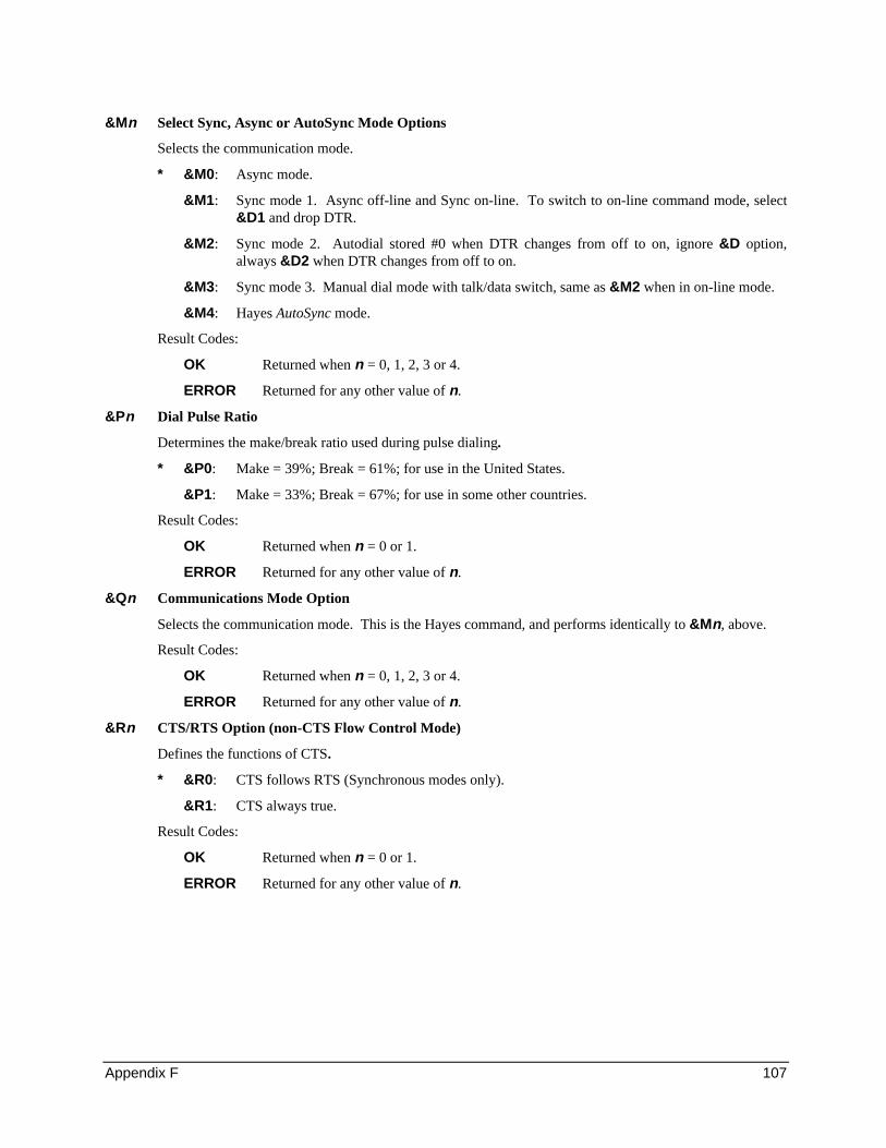
Appendix F 107
&Mn Select Sync, Async or AutoSync Mode Options
Selects the communication mode.
* &M0: Async mode.
&M1: Sync mode 1. Async off-line and Sync on-line. To switch to on-line command mode, select&D1 and drop DTR.
&M2: Sync mode 2. Autodial stored #0 when DTR changes from off to on, ignore &D option,always &D2 when DTR changes from off to on.
&M3: Sync mode 3. Manual dial mode with talk/data switch, same as &M2 when in on-line mode.
&M4: Hayes AutoSync mode.
Result Codes:
OK Returned when n = 0, 1, 2, 3 or 4.
ERROR Returned for any other value of n.
&Pn Dial Pulse Ratio
Determines the make/break ratio used during pulse dialing.
* &P0: Make = 39%; Break = 61%; for use in the United States.
&P1: Make = 33%; Break = 67%; for use in some other countries.
Result Codes:
OK Returned when n = 0 or 1.
ERROR Returned for any other value of n.
&Qn Communications Mode Option
Selects the communication mode. This is the Hayes command, and performs identically to &Mn, above.
Result Codes:
OK Returned when n = 0, 1, 2, 3 or 4.
ERROR Returned for any other value of n.
&Rn CTS/RTS Option (non-CTS Flow Control Mode)
Defines the functions of CTS.
* &R0: CTS follows RTS (Synchronous modes only).
&R1: CTS always true.
Result Codes:
OK Returned when n = 0 or 1.
ERROR Returned for any other value of n.

T1 Modem Bank108
&Sn Data Set Ready Option
Controls the functions of DSR. DSR indicates when the modem is connected to a communications channeland is ready. Async mode only. If the modem is in Sync mode, DSR is on during handshake and when on-line. DSR is off in test or idle mode.
* &S0: DSR always on.
&S1: DSR on during handshake and when on-line; off in test or idle modes.
Result Codes:
OK Returned when n = 0 or 1.
ERROR Returned for any other value of n.
&Tn Self Test Commands
Used to configure and place the modem in various test modes as defined by CCITT V.54. These tests aretypically used to verify the analog and digital portions of a modem’s operation.
&T0: Terminate test.
&T1: Local analog loopback.O: low frequency band.A: high frequency band.
&T3: Local activate remote digital loopback (RDL).
* &T4: Grant request from remote for RDL test.
&T5: Deny request from remote for RDL test.
&T6: Remote digital loopback test.
&T7: Remote digital loopback with self test.
&T8: Local analog loopback with self test.
Result Codes:
OK Returned when n = 0, 3, 4, 5, 7 or 8.
CONNECT Returned when n = 1 or 6.
ERROR Returned for any other value of n.

Appendix F 109
&Vn View Active Configuration and Stored Profile
Displays the active and stored profiles (commands and S register settings), and any stored telephonenumbers. The following example illustrates typical &V information for the Digi Modem/Xem.
&V0: View active file, stored profile #0, and stored phone numbers.
&V1: View active file, stored profile #1, and stored phone numbers.
EXAMPLE:
ACTIVE PROFILE:
B1 E1 L2 M1 N1 P Q0 V1 W0 X4 Y0 &B1 &C1 &D2 &G0 &J0 &K3 &L0 &P0 &Q0&R0 &S0 &U0 &X0 &Y0%A013 %C1 %E1 %G0 %01 \A3 \C0 \G0 \J0 \K5 \N3 \Q3 \T000 \V1 \X0 -J1"H3 "O016S00:000 S01:000 S02:043 S03:013 S04:010 S05:008 S06:002 S07:030S08:002 S09:006 S10:014 S11:095 S12:050 S18:000 S25:005 S26:001S37:000
STORED PROFILE 0:
B1 E1 L2 M1 N1 P Q0 V1 W0 X4 Y0 &B1 &C1 &D2 &G0 &J0 &K0 &L0 &P0 &Q0&R0 &S0 &U0 &X0 &Y0%A013 %C1 %E1 %G0 %01 \A3 \C0 \G0 \J0 \K5 \N3 \Q3 \T000 \V0 \X0 -J1"H3 "O016S00:000 S02:043 S06:002 S07:030 S08:002 S09:006 S10:014 S11:095S12:050 S18:000 S25:005 S26:001 S37:000
TELEPHONE NUMBERS:
&Z0= &Z1= &Z2= &Z3=
Result Codes:
OK Returned when n = 0 or 1.
ERROR Returned for any other value of n.
&Wn Store Active Profile
Stores certain command options and S register values into one of the two nonvolatile stored profilelocations:
&W0: Save active configuration as user profile 0.
&W1: Save active configuration as user profile 1.
Result Codes:
OK Returned when n = 0 or 1.
ERROR Returned for any other value of n.

T1 Modem Bank110
&Xn Sync Transmit Clock Source
Determines how the DTE transmit clock is generated while the modem is in synchronous modes.
* &X0: The modem generates the transmit clock and applies it to pin 15 (EIA-232).
&X1: The DTE generates the transmit clock on pin 25 (EIA-232) and the modem applies it to pin 15(EIA-232)
&X2: The modem derives the transmit clock from the receive carrier signal and applies it to pin 15(EIA-232).
Result Codes:
OK Returned when n = 0, 1 or 2.
ERROR Returned for any other value of n.
&Yn Select Stored Profile on Powerup
Selects which user profile will be recalled into the active profile when the modem is powered up.
&Y0: Select user profile 0.
&Y1: Select user profile 1.
Result Codes:
OK Returned when n = 0 or 1.
ERROR Returned for any other value of n.
&Zn=x Store Telephone Number
Stores a dialing string x in one of four non-volatile memory locations n. Dialing strings can be up to 36characters long, including dial modifiers; spaces are not counted.
n=0-3
x=0-9, A, B, C, D, #, *, T, P, R, W, @, comma, !, ; (dial string)

Appendix F 111
AT% (Percent) Commands
%An Set Autoreliable Fallback Character
Allows the user to specify the character that tells the modem to return (or fall back) from autoreliable(MNP) mode to a normal connection on the answering modem.
Result Codes:
OK Returned when n = 0-127 (ascii character set).
ERROR Returned for any other value of n.
Default: 0x0D
%Cn Data Compression
Controls the MNP Class 5 compression. The modem can only perform data compression on an errorcorrected link.
%C0: No compression.
* %C1: MNP Class 5 compression.
Result Codes:
OK Returned when n = 0 or 1.
ERROR Returned for any other value of n.
%Gn Auto Fallforward/Fallback Enable
Selects the auto fallback option.
%G0: Disabled.
* %G1: Enabled.
Result Codes:
OK Returned when n = 0 or 1.
ERROR Returned for any other value of n.

T1 Modem Bank112
AT\ (Backslash) Commands
\An Block Size for V.42
Sets the maximum block size during connection. This option forces the modem chip set to transmit smallerblocks of data. The command is typically used for poor quality telephone lines where transmitting smallerblocks reduces retransmission and improves throughput.
\A0: Max 64 characters.
\A1: Max 128 characters.
\A2: Max 192 characters.
* \A3: Max 256 characters.
Result Codes:
OK Returned when n = 0, 1, 2 or 3.
ERROR Returned for any other value of n.
\Bn Transmit Break
Sends a break to the remote modem. Equivalent to using the <Break> key on your terminal. Thiscommand can be used if your keyboard does not have a <Break> key.
\B0 - \B9: BREAK length, in 100 ms increments.
Result Codes:
OK If connected in data mode.
ERROR If not connected, or connected in FAX mode.
\Cn Set Autoreliable Buffer
Defines whether the modem buffers the data it receives during link negotiation.
* \C0: Do not buffer data.
\C1: Buffers data on answering modem for 4 seconds, until 200 characters have been buffered, thenswitches to normal mode and the buffered characters are passed to the serial port. If a SYNcharacter is detected, reliable mode is attempted.
\C2: Does not buffer data on answering modem. Switches to normal mode upon receipt ofautoreliable character and passes it to serial port.
Result Codes:
OK Returned when n = 0, 1 or 2.
ERROR Returned for any other value of n.
\Gn Set Modem Port Flow Control (Only in Normal Mode)
Selects the modem’s DCE or port flow control. If the modem is receiving data from the remote modemfaster than it can be processed, enabling port flow control allows the modem to handle the data efficiently.
* \G0: Disable port flow control.
\G1: Set port flow control to XON/XOFF flow control.
Result Codes:
OK Returned when n = 0 or 1.
ERROR Returned for any other value of n.

Appendix F 113
\Jn Constant DTE Speed Option
* \J0: DCE and DTE rates are independent.
\J1: DTE rate adjusts to DCE connection rate after online.
Result Codes:
OK Returned when n = 0 or 1.
ERROR Returned for any other value of n.
\Kn Set Break Control
Selects the way in which the modem handles a break signal. The Modem Xem can handle a break in one ofthree ways: expedited destructive, expedited, or queued break.
In online data mode with V.42 protocol or normal mode, then break signal to DTE through EIA-232,
0, 2, 4: Enter online command mode but do not send break to remote modem.
1: Empty the data buffers and send break to the remote modem immediately.
3: Immediately send break to the remote modem.
* 5: Send break to the remote modem in sequence with data.
In online data mode with direct mode, then receive break at serial port,
0, 2, 4: Immediately send break and enter online command state.
1, 3, *5: Immediately send break through.
In online command mode with V.42 protocol or normal mode, and the DTE issues a transmit breakcommand,
0, 1: Empty the data buffers and send break to the remote modem.
2, 3: Immediately send break to the remote modem.
4, *5: Send break to the remote modem in sequence with data.
In online data mode with normal mode, receive break signal from remote at modem port, send to serialport,
0, 1: Empty the data buffers and send break to the local DTE.
2, 3: Immediately send break to the local DTE.
4, *5: Send break to the local DTE in sequence with data.
Result Codes:
OK Returned when n = 0, 1, 2, 3, 4 or 5.
ERROR Returned for any other value of n.

T1 Modem Bank114
\Nn Modem Protocol Options
Selects the type of data connection the modem can establish.
\N0: Normal mode. No protocol, but flow control is allowed.
\N1: Direct mode. No protocol and no flow control is allowed.
\N2: MNP reliable mode.
* \N3: LAPM, MNP or Normal mode
\N4: LAPM or MNP mode.
Result Codes:
OK Returned when n = 0, 1, 2, 3 or 4.
ERROR Returned for any other value of n.
\Qn DTE Flow Control Options
Selects the flow control method the modem provides to the DTE to prevent the modem’s buffer fromoverflowing with data. A data buffer holds the data until the modem is ready to transmit it. When the databuffer is full, flow control instructs the DTE to stop sending to the modem while the modem continues tosend characters.
\Q0: Disables flow control.
\Q1: XON/XOFF software flow control.
\Q2: CTS flow control to DTE.
* \Q3: RTS/CTS hardware flow control.
Result Codes:
OK Returned when n = 0, 1, 2 or 3.
ERROR Returned for any other value of n.
\Tn Set Inactivity Timer
Permits the modem to disconnect if no data activity has occurred for the selected period of time.
* n=0: Disable inactivity timer.
n=1-90: Length in minutes.
\Vn Protocol Result Code
Enables/disables the protocol result code on connect (effective only with W0 and W2 options)
* \V0: Disable protocol result code (Connect 9600 ).
\V1: Enable protocol result code (Connect 9600/LAPM ).
Result Codes:
OK Returned when n = 0 or 1.
ERROR Returned for any other value of n.

Appendix F 115
\Xn Set XON/XOFF Passthrough Option
Valid only if XON/XOFF flow control is enabled, such as with \G1 or \Q1; otherwise, XON/XOFF will notbe detected by the modem, and thus will always pass through.
* \X0: Process XON/XOFF per \G and \Q options; do not pass XON/XOFF to the remote modem orlocal DTE.
\X1: Process XON/XOFF per \G and \Q options; always pass XON/XOFF to the remote modem orlocal DTE.
Result Codes:
OK Returned when n = 0 or 1.
ERROR Returned for any other value of n.

T1 Modem Bank116
AT- (Dash) Commands
-Jn Set V.42 Detection Phase
Defines whether the originating modem sends a sequence to the answering modem to determine the type oferror correction it has enabled.
-J0: Disables the V.42 detection phase.
* -J1: Enables the V.42 detection phase.
Result Codes:
OK Returned when n = 0 or 1.
ERROR Returned for any other value of n.

Appendix F 117
AT" (Quote) Commands
"Hn V.42bis Compression Control
Controls V.42bis data compression over an error correction link.
"H0 : Disable V.42bis.
"H1 : Enable V.42bis only when transmitting data.
"H2 : Enable V.42bis only when receiving data.
* "H3 : Enable V.42bis for both directions.
Result Codes:
OK Returned when n = 0, 1, 2 or 3.
ERROR Returned for any other value of n.
"Nn V.42bis Dictionary Size
512 bytes < btlz_dict_size < maximum RAM allows, default is 1.5 Kbytes.
"N0 : 512 bytes.
"N1 : 1024 bytes.
"N2 : 1536 bytes
Result Codes:
OK Returned when n = 0, 1 or 2.
ERROR Returned for any other value of n.
"On Select V.42bis Maximum String Length
Selects the string size for V.42bis compression.
n = 6-64.
* Default = 32

T1 Modem Bank118
Class 1 FAX Commands
The Digi Modem/Xem supports FAX commands conforming to EIA standard 578. These commands are given herewith short descriptions; complete descriptions are given in the standard, available from the Electronic IndustryAssociation. It also supports ECM mode and V.17terbo at 19.2K bps.
+FCLASS? Service Class Indication
Causes the modem to display the current setting. The modem can operate either as a Class 0 data modem ora Class 1 FAX modem. Returns 0 for a Class 0 data modem, or 1 for a Class 1 FAX modem.
+FCLASS=? Service Class Capabilities
Causes the modem to display the classes it supports. Returns “0” if set up for data mode; “0, 1 ” indicatesthat the modem is capable of data and Class 1 FAX services.
+FCLASS=n Service Class Selection
Sets the modem for Class 0 (data) or Class 1 (FAX) operation.
+FCLASS=0 Sets the modem for Class 0 data operation.
+FCLASS=1 Sets the modem for Class 1 FAX operation.
+FTS=? FTS Range Capabilities
Modem returns “0-255 ”.
+FTS=n Transmission Silence
Causes the modem to stop transmitting data and pause for n x 10 ms. Modem returns OK after timer hasexpired.
+FRS=? FRS Range Capabilities
Modem returns “0-255 ”.
+FRS=n Receive Silence
Causes the modem to stop transmitting data and pause for n x 10 ms for silence; then the timer is reloaded.
+FTM=? FAX Normal Mode Transmit Capabilities
Causes the modem to output the transmit modulations supported by the modem. See Table 9.
+FTM=n Modem Initiate Training
Causes the modem to initiate training with modulation of type n. Table 9 shows the values you can enter forthis command and the meaning of those values.
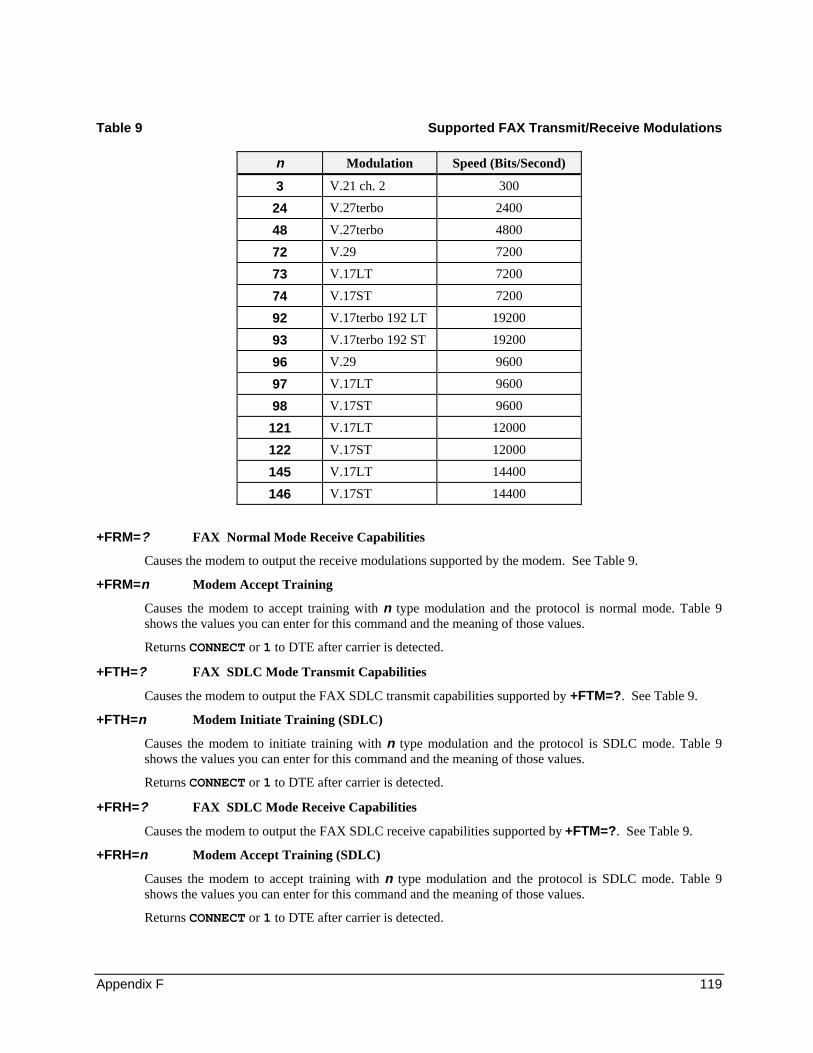
Appendix F 119
Table 9 Supported FAX Transmit/Receive Modulations
n Modulation Speed (Bits/Second)
3 V.21 ch. 2 300
24 V.27terbo 2400
48 V.27terbo 4800
72 V.29 7200
73 V.17LT 7200
74 V.17ST 7200
92 V.17terbo 192 LT 19200
93 V.17terbo 192 ST 19200
96 V.29 9600
97 V.17LT 9600
98 V.17ST 9600
121 V.17LT 12000
122 V.17ST 12000
145 V.17LT 14400
146 V.17ST 14400
+FRM=? FAX Normal Mode Receive Capabilities
Causes the modem to output the receive modulations supported by the modem. See Table 9.
+FRM=n Modem Accept Training
Causes the modem to accept training with n type modulation and the protocol is normal mode. Table 9shows the values you can enter for this command and the meaning of those values.
Returns CONNECT or 1 to DTE after carrier is detected.
+FTH=? FAX SDLC Mode Transmit Capabilities
Causes the modem to output the FAX SDLC transmit capabilities supported by +FTM=?. See Table 9.
+FTH=n Modem Initiate Training (SDLC)
Causes the modem to initiate training with n type modulation and the protocol is SDLC mode. Table 9shows the values you can enter for this command and the meaning of those values.
Returns CONNECT or 1 to DTE after carrier is detected.
+FRH=? FAX SDLC Mode Receive Capabilities
Causes the modem to output the FAX SDLC receive capabilities supported by +FTM=?. See Table 9.
+FRH=n Modem Accept Training (SDLC)
Causes the modem to accept training with n type modulation and the protocol is SDLC mode. Table 9shows the values you can enter for this command and the meaning of those values.
Returns CONNECT or 1 to DTE after carrier is detected.

T1 Modem Bank120
Class 2 FAX Commands
+FAA=n FAX Auto Answer Enable
Command Syntax: +FAA=<value>
0: Answer as FAX modem of type specified by +FCLASS.1: Automatically determine whether to answer as FAX or data modem.
+FAXERR T.30 Session Error Report
Command syntax: +FAXERRResponse syntax: +FAXERRR=<value>
0-9 Call placement and termination.0: Normal and proper end of connection.1: Ring detected without successful handshake.2: Call aborted, from +FK or <CAN>
10-19 Transmit Phase A & miscellaneous errors.
20-39 Transmit Phase B hang-up codes.20: Unspecified transmit Phase B error.23: COMREC invalid command received.25: DCS sent 3 times without response.27: Failure to train.
40-49 Transmit Phase C hang-up codes.40: Unspecified transmit Phase C error.
50-69 Transmit Phase D hang-up codes.52: No response to MPS repeated 3 times.53: Invalid response to MPS.54: No response to EOP repeated 3 times.55: Invalid response to EOP.56: No response to EOM repeated 3 times.57: Invalid response to EOM.
70-89 Receive Phase B hang-up codes.
90-99 Receive Phase C hang-up codes.90: Unspecified receive Phase C error.
100-119 Receive Phase D hang-up codes.100:Unspecified receive Phase D error.
120-255 Reserved codes.

Appendix F 121
+FBOR Data Bit Order Selection.
Command syntax: +FBOR=<value>
0: Direct bit order for both Phase C data and Phase B/D data.1: Reversed bit order for Phase C data and direct bit order for Phase B/D data.2: Direct bit order for Phase C data and reversed bit order for Phase B/D data.3: Reversed bit order for both Phase C data and for Phase B/D data.
Note:Direct bit order: First bit transferred of each byte on the DTE-DCE link is the first bit transferred
in the PSTN data carrier.
Reversed bit order: Last bit transferred of each byte on the DTE-DCE link is the first bit transferredin the PSTN data carrier.
+FCQ Copy Quality Checking
Command syntax: +FCQ=<value>
0: Disables copy quality checking. The modem will generate Copy Quality OK (MCF) responses tocomplete pages and set +FPTS=1.
+FCR Capability to Receive
Command syntax: +FCR=<value>
0: Indicates the modem will not receive message data.1: Indicates the modem can receive message data.
+FCTCRTY ECM Retry Count
Command syntax: +FCTCRTY=<value>
0: Disable error correcting mode retries. Error correcting mode is not supported.

T1 Modem Bank122
+FDCC FAX Capability Parameters
Command syntax: +FDCC=VR,BR,WD,LN,DF,EC,BF,STResponse syntax: VR,RB,WD,LN,DF,EC,BF,STValid Values:
VR: Vertical resolution0: Normal, 98 lpi1: Fine, 196 lpi
BR: Bit rate0: 2400 bps V.27ter1: 4800 bps V.27ter2: 7200 bps V.29 or V.173: 9600 bps V.29 or V.174: 12000 bps V.33 or V.175: 14400 bps V.33 or V.17
WD: Page width0: 1728 pixels in 215 mm
LN: Page length0: A4, 297 mm2: Unlimited length
DF: Data compression format0: 1-D modified Huffman
EC: Error Correction0: Disable ECM
BF: Binary file transfer0: Disable BFT
ST: Scan time/line
VR=Normal VR=Fine0: 0 ms 0 ms1: 5 ms 5 ms2: 10 ms 5 ms3: 10 ms 10 ms4: 20 ms 10 ms5: 20 ms 20 ms6: 40 ms 20 ms7: 40 ms 40 ms
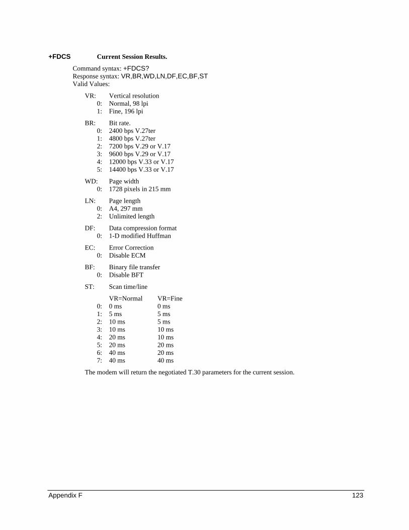
Appendix F 123
+FDCS Current Session Results.
Command syntax: +FDCS?Response syntax: VR,BR,WD,LN,DF,EC,BF,STValid Values:
VR: Vertical resolution0: Normal, 98 lpi1: Fine, 196 lpi
BR: Bit rate.0: 2400 bps V.27ter1: 4800 bps V.27ter2: 7200 bps V.29 or V.173: 9600 bps V.29 or V.174: 12000 bps V.33 or V.175: 14400 bps V.33 or V.17
WD: Page width0: 1728 pixels in 215 mm
LN: Page length0: A4, 297 mm2: Unlimited length
DF: Data compression format0: 1-D modified Huffman
EC: Error Correction0: Disable ECM
BF: Binary file transfer0: Disable BFT
ST: Scan time/line
VR=Normal VR=Fine0: 0 ms 0 ms1: 5 ms 5 ms2: 10 ms 5 ms3: 10 ms 10 ms4: 20 ms 10 ms5: 20 ms 20 ms6: 40 ms 20 ms7: 40 ms 40 ms
The modem will return the negotiated T.30 parameters for the current session.
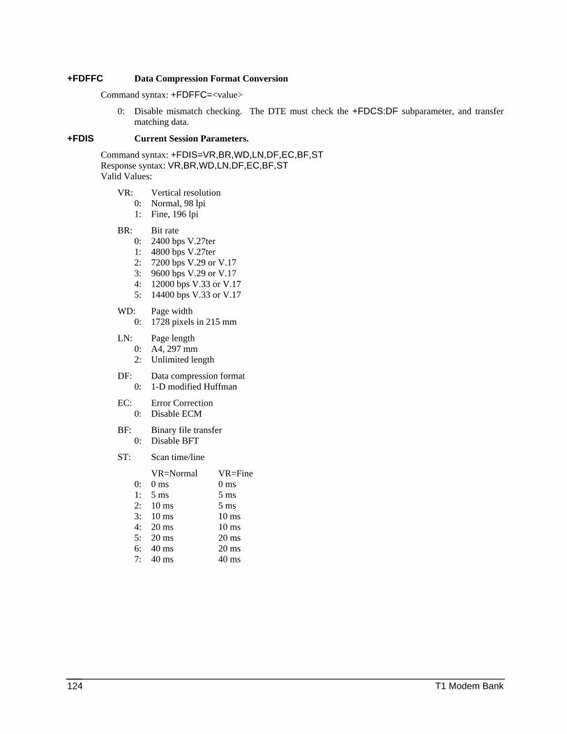
T1 Modem Bank124
+FDFFC Data Compression Format Conversion
Command syntax: +FDFFC=<value>
0: Disable mismatch checking. The DTE must check the +FDCS:DF subparameter, and transfermatching data.
+FDIS Current Session Parameters.
Command syntax: +FDIS=VR,BR,WD,LN,DF,EC,BF,STResponse syntax: VR,BR,WD,LN,DF,EC,BF,STValid Values:
VR: Vertical resolution0: Normal, 98 lpi1: Fine, 196 lpi
BR: Bit rate0: 2400 bps V.27ter1: 4800 bps V.27ter2: 7200 bps V.29 or V.173: 9600 bps V.29 or V.174: 12000 bps V.33 or V.175: 14400 bps V.33 or V.17
WD: Page width0: 1728 pixels in 215 mm
LN: Page length0: A4, 297 mm2: Unlimited length
DF: Data compression format0: 1-D modified Huffman
EC: Error Correction0: Disable ECM
BF: Binary file transfer0: Disable BFT
ST: Scan time/line
VR=Normal VR=Fine0: 0 ms 0 ms1: 5 ms 5 ms2: 10 ms 5 ms3: 10 ms 10 ms4: 20 ms 10 ms5: 20 ms 20 ms6: 40 ms 20 ms7: 40 ms 40 ms

Appendix F 125
+FDR Begin or continue Phase C Receive Data.
Command syntax: +FDR
This command will initiate a transition to Phase C data reception.
+FDT Begin Phase C Data Transmission.
Command syntax: +FDT
This command prefixes Phase C data transmission.
+FECM Error Correction Mode Control.
Command syntax: +FECM=<value>0: Error correcting mode disabled.
+FET Transmit Page Punctuation.
Command syntax: +FET=<ppm>0: [PPS-]MPS Another page next, same document.1: [PPS-]EOM Another document next.2: [PPS-]EOP No more pages or documents.3: PPS-NULL Another partial page next.4: [PPS-]PRI-MPS Another page, procedure interrupt.5: [PPS-]PRI-EOM Another document, procedure interrupt.6: [PPS-]PRI-EOP All done, procedure interrupt.7: CTC Continue to correct.
This command is used to punctuate page and document transmission, after one or more +FDT commands.
+FK Session Termination.
Command syntax: +FK
This command causes the modem to terminate the session in an orderly manner.
+FLID Local ID String.
Command syntax: +FLID=”<local ID string>”Valid values: ASCII string can be up to 20 characters.
Response syntax: +FLID=?Return value: (20), (32-127)
+FLNFC Page Length Format Conversion.
Command syntax: +FLNFC=<value>0: Disables mismatch checking. The DTE must check the +FDCS:LN subparameter, and transfer
matching data.
+FLPL Indicate Document to Poll.
Command syntax: +FLPL=<value>0: Indicates that the DTE has no document to poll.
+FMDL Request Model Identification.
Command syntax: +FMDL?Response value: The information text cannot exceed 2048 characters.
This command causes the modem to send one or more lines of information text which is used to identify theproduct.

T1 Modem Bank126
+FMFR Manufacturer’s Identification.
Command syntax: +FMFR?Response value: The information text cannot exceed 2048 characters.
This command causes the modem to send one or more lines of information text which is used to identify themanufacturer.
+FREV Request Product Revision Identification.
Command syntax: +FREV?Response value: The information text cannot exceed 2048 characters.
This command causes the modem to send one or more lines of information text which is used to identify theversion, revision level or data, or other pertinent information.
+FPHCTO DTE Phase C Response Time-out.
Command syntax: +FPHCTO=<value>
value = 0 - 255 (100 ms units)Default value: 30
This value determines how long the modem will wait for a command after reaching the end of data whentransmitting in Phase C.
+FPTS Page Transfer Status.
Command syntax: +FPTS=<ppr>1: MCF Page good.2: RTN Page good; retrain requested.3: RTP Page good; retrain requested.
+FRBC Phase C Receive Data Block Size.
Command syntax: +FRBC=<value>0: Stream mode, Phase C data is terminated by <DLE><ETX>.
+FREL Phase C Received EOL Alignment.
Command syntax: +FREL=<value>0: Indicates that EOL patterns are aligned as received.
+FSPL Request to Poll.
Command syntax: +FSPL=<value>0: Indicates that the DTE does not want to poll.
+FTBC Phase C Transmit Data Block Size.
Command syntax: +FTBC=<value>0: Stream mode, Phase C data is terminated by <DLE><ETX>.

Appendix F 127
Class 2 FAX Responses
+FCFR Indicate Confirmation to Receive.
Syntax: +FCFRUsage: Indicates the reception of an acceptable TCF training burst and valid DCS signal from the remote
machine.
+FCON Facsimile Connection Response.
Syntax: +FCONUsage: Indicates connection with a FAX machine. Generated in response to an originate command or
answer command.
+FCSI Reports the Remote ID.
Syntax: +FCSI:”<CSI ID string>”Usage: Reports the Called Station’s ID.
+FDCS Reports DCS Frame Information.
Syntax: +FDCS:VR,BR,WD,LN,DF,EC,BF,STUsage: Reports negotiated parameters for the current session. The subparameters are described in the
+FDCS command description.
+FDIS Reports DIS Frame Information.
Syntax: +FDIS:VR,BR,WD,LN,DF,EC,BF,STUsage: Reports remote FAX capabilities and intentions. The subparameters are described in the +FDCS
command description.
+FET Post Page Message Response.
Syntax: +FET:<ppm>Usage: Generated by the receiving modem after the end of Phase C reception, on receipt of the post-page
message from the transmitting station. The <ppm> codes are described in the +FET commanddescription.
+FHNG Call Termination with Status.
Syntax: +FHNG:<hangup status code>Usage: Indicates that the call has been terminated. The <hang-up status code> values are described in the
+FAXERR command description.
+FPTS Receive/Transmit Page Transfer Status.
Syntax: +FPTS:<ppr>Usage: Reports a <ppr> number representing the copy quality and related post-page message. The valid
<ppr> values are defined in the +FPTS command description.
+FTSI Report the Remote ID.
Syntax: +FTSI:"<TSI ID string>"Usage: Reports the transmitting station’s ID.

T1 Modem Bank128
S Registers
All bit-mapped registers are read-only. The appropriate AT command which controls the relevant bits in the Sregister should be used to change the value.
The factory default values are stored in ROM and are loaded into the active configuration at powerup or by theATZn command. In addition, the designated default profile can be changed by entering the &Yn command where nis one of the two possible user profiles.
All of the factory default values may be loaded at any time by entering the &F command.

Appendix F 129
S Register Definitions
S0 Autoanswer Ring Count
Sets the number of the rings required before the modem automatically answers a call. Setting this register to zerodisables autoanswer mode.
Range: 0-255Default: 000Units: rings
S1 Ring Count
The value of S1 is incremented with each ring. If no rings occur over an 8 second interval, this register is cleared.
Range: 0-255Default: 000Units: rings
S2 Escape Character (user defined)
S2 holds the decimal value of the ASCII character used as the escape character. The default value corresponds to anASCII +. A value over 127 disables the escape process, i.e., no escape character will be recognized.
Range: 0-255Default: 043Units: ASCII
S3 Carriage Return <CR> Character (user defined)
Sets the command line and result code terminator character. Pertains to asynchronous operation only.
Range: 0-127, ASCII decimalDefault: 013 (carriage return)Units: ASCII
S4 Line Feed <LF> Character (user defined)
Sets the character recognized as a line feed. Pertains to asynchronous operation only. The line feed controlcharacter is output after the carriage return control character if verbose result codes are used.
Range: 0-27, ASCII decimalDefault: 010 (Line Feed)Units: ASCII
S5 Back Space <BS> Character (user defined)
Sets the character recognized as a backspace. Pertains to asynchronous operation only. The modem will notrecognize the backspace character if it is set to a value that is greater than 32 ASCII. This character can be used toedit a command line. When the echo command is enabled, the modem echoes back to the local DTE, the backspacecharacter, an ASCII space character, and a second backspace character; this means a total of three characters aretransmitted each time the modem processes the backspace character.
Range: 0-127, ASCII decimalDefault: 008 (backspace)Units: ASCII

T1 Modem Bank130
S6 Wait Before Dialing
Sets the length of time, in seconds, that the modem must wait (pause) after going off-hook before dialing the firstdigit of the telephone number. The modem always pauses for a minimum of 2 s, even if the value of S6 is less than2 s. The wait for dial tone call progress feature (W dial modifier in the dial string) will override the value in registerS6. This operation, however, may be affected by some ATX options according to country restrictions.
Range: 2-255Default: 002Units: seconds
S7 Wait for Carrier
Sets the time, in seconds, that the modem must wait before hanging up because carrier is not detected. The timer isstarted when the modem finishes dialing (originate), or goes off-hook (answer). In originate mode, the timer is resetupon detection of answer tone if allowed by country restrictions. This timer also specifies the wait for silence timefor the @ dial modifier in seconds. S7 is not associated with the W dial modifier.
Range: 1-255Default: 060Units: seconds
S8 Pause Time for Command or Dial Modifier
Sets the time, in seconds, that the modem must pause when the “,” dial modifier is encountered in the dial string.
Range: 0-255Default: 002Units: seconds
S9 Carrier Validation Time
Sets the time, in tenths of a second, that the carrier must be present before the modem considers it valid and turns onRLSD. As this time is increased, there is less chance to detect a false carrier due to noise from the telephone line.
Range: 1-255Default: 006 (0.6 second)Units: 0.1 s
S10 Lost Carrier Delay
Sets the length of time, in tenths of a second, that the modem waits before hanging up after a loss of carrier. Thisallows for a temporary carrier loss without causing the local modem to disconnect. When register S10 is set to 255,the modem functions as if a carrier is always present.
The actual interval the modem waits before disconnecting is the value in register S10 minus the value in register S9.Therefore, the S10 value must be greater than the S9 value or else the modem disconnects before it recognizes thecarrier.
Range: 1-255Default: 014 (1.4 s)Units: 0.1 s
S11 DTMF Duration and Interdigit Delay
Range: 50-255Default: 095 msUnits: 0.001 s

Appendix F 131
S12 Guard Time
Defines the maximum period, in 2-hundredths of a second, allowed between consecutive asynchronous escapecharacters (+) for the escape sequence to be considered valid.
Range: 0-255Default: 050 (1 s)Units: 0.02 s
S14 Bit-Mapped Options
Indicates the status of command options.
Default: (AAh), (170d), (10101010b)
Bit 0 Reserved.
Bit 1 Command echo (En)
0 E0 Echo off1 E1 Echo on
Bit 2 Response (Qn)
0 Q0 on1 Q1 off
Bit 3 Result codes (Vn)
0 V0 is selected1 V1 is selected
Bit 4 Dumb Mode
0 dumb mode off (normal)1 dumb mode on
Bit 5 Tone/Pulse Dialing
0 T tone1 P pulse
Bit 6 Reserved
Bit 7 Originate/Answer
0 answer1 originate

T1 Modem Bank132
S16 Bit-Mapped Option Status
Indicates the test in progress status.
Default: 000
Bit 0 Local analog loopback
0 local ALB disabled1 local ALB enabled (&T1)
Bit 1 Reserved
Bit 2 Local digital loopback
0 local DL disabled1 local DL enabled (&T3)
Bit 3 Remote digital loopback (RDL) status
0 RDL off1 RDL in progress
Bit 4 RDL requested
0 RDL not active1 RDL active (&T6)
Bit 5 RDL w/ self-test
0 RDL w/ self-test disabled1 RDL w/ self-test enabled (&T7)
Bit 6 Local analog loopback (ALB) w/ self-test
0 ALB w/ self-test disabled1 ALB w/ self-test enabled (&T8)
Bit 7 Reserved
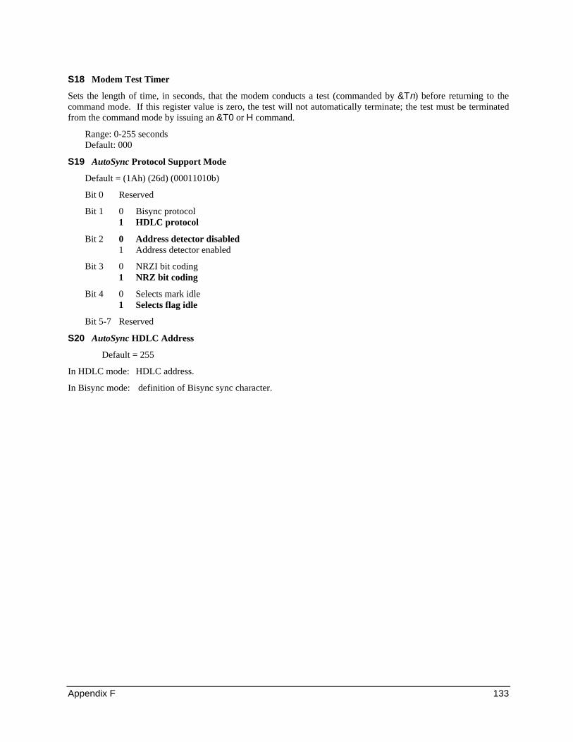
Appendix F 133
S18 Modem Test Timer
Sets the length of time, in seconds, that the modem conducts a test (commanded by &Tn) before returning to thecommand mode. If this register value is zero, the test will not automatically terminate; the test must be terminatedfrom the command mode by issuing an &T0 or H command.
Range: 0-255 secondsDefault: 000
S19 AutoSync Protocol Support Mode
Default = (1Ah) (26d) (00011010b)
Bit 0 Reserved
Bit 1 0 Bisync protocol1 HDLC protocol
Bit 2 0 Address detector disabled1 Address detector enabled
Bit 3 0 NRZI bit coding1 NRZ bit coding
Bit 4 0 Selects mark idle1 Selects flag idle
Bit 5-7 Reserved
S20 AutoSync HDLC Address
Default = 255
In HDLC mode: HDLC address.
In Bisync mode: definition of Bisync sync character.

T1 Modem Bank134
S21 Bit-Mapped Options
Indicates the status of command options.
Default: (30h), (048d), (00110000b)
Bit 0 Reserved.
Bit 1 Reserved
Bit 2 CTS behavior (&Rn)
0 &R0 CTS follows RTS1 &R1 CTS is always on
Bit 4, 3 DTR behavior (&Dn)
00 &D0 ignore01 &D1 return to command mode10 &D2 disconnect11 &D3 reset modem
Bit 5 DCD behavior (&Cn)
0 &C0 DCD is always on1 &C1 DCD is on after connect
Bit 6 DSR behavior (&Sn)
0 &S0 DSR is always on1 &S1 DSR is on after connect
Bit 7 Reserved
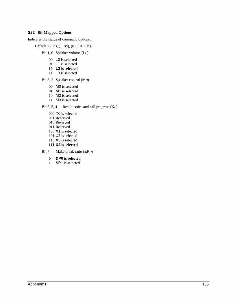
Appendix F 135
S22 Bit-Mapped Options
Indicates the status of command options.
Default: (76h), (118d), (01110110b)
Bit 1, 0 Speaker volume (Ln)
00 L0 is selected01 L1 is selected10 L2 is selected11 L3 is selected
Bit 3, 2 Speaker control (Mn)
00 M0 is selected01 M1 is selected10 M2 is selected11 M3 is selected
Bit 6, 5, 4 Result codes and call progress (Xn)
000X0 is selected001 Reserved010 Reserved011 Reserved100X1 is selected101X2 is selected110X3 is selected111X4 is selected
Bit 7 Make break ratio (&Pn)
0 &P0 is selected1 &P1 is selected

T1 Modem Bank136
S23 Bit-Mapped Options
Indicates the status of command options.
Default: (001), (015d), (00001111b)
Bit 0 Grant RDL
0 &T5 is selected1 &T4 is selected
Bit 3, 2, 1 Reserved
Bit 5, 4 Word length (7 bits)
00 even parity01 space parity10 odd parity11 mark parity
Bit 7, 6 Guard tones (&Gn)
00 disabled01 550 Hz10 1800 Hz11 not used
S25 DTR Debounce time
Sets the length of time that the modem will ignore DTR for before hanging up. Its units are seconds for synchronousmode 1 and one hundredths of a second for other modes.
Range: 0-255 (1 second for synchronous mode 1; 0.01 s otherwise)Default: 005Units: 0.05 s
S26 RTS to CTS Delay Interval
Sets the time delay, in hundredths of a second, before the modem turns CTS ON after detecting an OFF-to-ONtransaction on RTS when &R0 is commanded. Pertains to synchronous operation only.
Range: 0-255Default: 001Units: 0.01 s
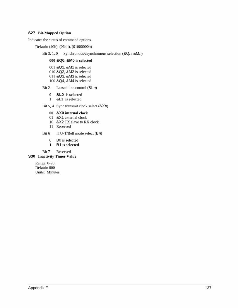
Appendix F 137
S27 Bit-Mapped Option
Indicates the status of command options.
Default: (40h), (064d), (01000000b)
Bit 3, 1, 0 Synchronous/asynchronous selection (&Qn, &Mn)
000&Q0, &M0 is selected
001&Q1, &M1 is selected010&Q2, &M2 is selected011&Q3, &M3 is selected100&Q4, &M4 is selected
Bit 2 Leased line control (&Ln)
0 &L0 is selected1 &L1 is selected
Bit 5, 4 Sync transmit clock select (&Xn)
00 &X0 internal clock01 &X1 external clock10 &X2 TX slave to RX clock11 Reserved
Bit 6 ITU-T/Bell mode select (Bn)
0 B0 is selected1 B1 is selected
Bit 7 ReservedS30 Inactivity Timer Value
Range: 0-90Default: 000Units: Minutes

T1 Modem Bank138
S37 Desired DCE Speed
Default = 000
0 = Attempt to connect at the last AT speed3 = Attempt a 300 bits/s connection5 = Attempt a 1200 bits/s connection6 = Attempt a 2400 bits/s connection7 = Attempt a 4800 bits/s connection8 = Attempt a 7200 bits/s connection9 = Attempt a 9600 bits/s connection10 = Attempt a 12000 bits/s connection11 = Attempt a 14400 bits/s connection12 = Attempt a 16800 bits/s connection13 = Attempt a 19200 bits/s connection14 = Attempt a 21600 bits/s connection15 = Attempt a 24000 bits/s connection16 = Attempt a 26400 bits/s connection17 = Attempt a 28800 bits/s connection18 = Attempt a 31200 bits/s connection19 = Attempt a 33600 bits/s connection
S40 Bit-Mapped Option Status
Default = 077
Bit 0 Automode select (Nn)
0 N0 disabled1 N1 enabled
Bit 1-5 Reserved
Bit 6 V.42 detection phase (-Jn)
0 -J0 disabled1 -J1 enabled
Bit 7 Reserved
S41 Connect Message Display
Default = 000
0 = CONNECT with DTE speed1 = CONNECT with carrier, protocol, and compression2 = CONNECT with DCE speed
S42 V.32 Retrain Operation (&Bn)
Default = 001
0 = &B0 is selected1 = &B1 is selected2 = &B2 is selected
S43 Auto Fallback Character for MNP Negotiation
0 disabled1-127 enabledDefault 013

Appendix F 139
S44 Bit-Mapped Option Status
Default = (17h) (023d) (00010111b)
Bit 0 V.42bis status
0 disabled1 enabled
Bit 1-2 V.42bis selection ("Hn)
00 "H0 is selected01 "H is selected10 "H2 is selected11 "H3 selected
Bit 3 Reserved
Bit 4 Auto fallback/fall forward selection (%Gn)
0 %G0 is selected1 %G1 is selected
Bit 5-7 Reserved
S46 Automatic Sleep Timer
0-255 Sleep delay - unit = 100 ms
Specifies the time the controller waits before going to sleep. The data pump is not affected.
0-254 = 0-25.4 s
Default value = 255 (disabled)
S47 Forced Sleep Timer with Powerdown Mode in PCMCIA
0-255 Sleep delay - unit = 100 ms
Specifies the time the controller waits before going to sleep. The data pump is not affected.
0-254 = 0-25.4 s
Default value = 255 (disabled)
S48 Set Autoreliable Buffer (\Cn)
Default = 000
0 \C0 is selected1 \C1 is selected2 \C2 is selected
S49 Set Maximum Block Size
Default = 255
63 = 64 bytes = \A0127 = 128 bytes = \A1191 = 192 bytes = \A2255 = 256 bytes = \A3
S50 FAX/Data Mode Selection
Default = 000
0 Data mode1 FAX mode

T1 Modem Bank140
S51 Data/FAX DTE Flow Control Selection
Default = 003
Bit 0-2 (&Kn, \Qn)
000&K0, \Q0 are selected001&K1, \Q1 are selected010&K2, \Q2 are selected011&K3 , \Q3 are selected
Bit 3 Reserved
Bit 4 XON/XOFF flow control (\Gn)
0 \G0 is selected1 \G1 is selected
Bit 5 DTE/DCE rate (\Jn)
0 \J0 is selected1 \J1 is selected
Bit 6, 7 XON/XOFF pass-through control (\Xn)
00 \X0 is selected01 \X1 is selected
S52 Break Control Option
Reflects the &Kn value.
Range: 0-5Default: 5
S53 Modem Operating Mode (\Nn)
Default = 003
0 \N0 is selected1 \N1 is selected2 \N2 is selected3 \N3 is selected4 \N4 is selected
S54 Bit-Mapped Option Status
Default = 000
Bit Meaning0 B2 is selected1 B3 is selected2-6 Reserved7 0 \V0 is selected
1 \V1 is selected
S57 V.42bis Dictionary Size (see AT"N )
Default = 002Range: 0-2
0 512 bytes1 1024 bytes2 1536 bytes
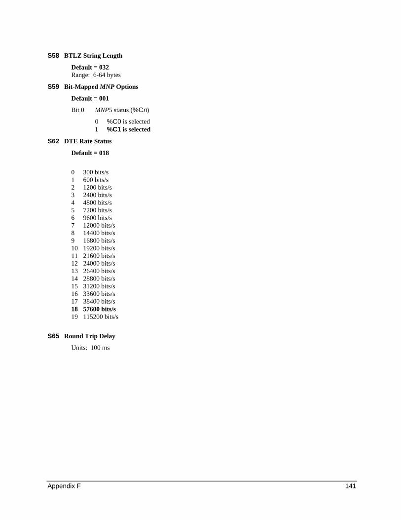
Appendix F 141
S58 BTLZ String Length
Default = 032Range: 6-64 bytes
S59 Bit-Mapped MNP Options
Default = 001
Bit 0 MNP5 status (%Cn)
0 %C0 is selected1 %C1 is selected
S62 DTE Rate Status
Default = 018
0 300 bits/s1 600 bits/s2 1200 bits/s3 2400 bits/s4 4800 bits/s5 7200 bits/s6 9600 bits/s7 12000 bits/s8 14400 bits/s9 16800 bits/s10 19200 bits/s11 21600 bits/s12 24000 bits/s13 26400 bits/s14 28800 bits/s15 31200 bits/s16 33600 bits/s17 38400 bits/s18 57600 bits/s19 115200 bits/s
S65 Round Trip Delay
Units: 100 ms

T1 Modem Bank142
S72 DTE Speed Select During Data Transfer
Default = 000
0 last autobaud speed1 300 bits/s2 600 bits/s3 1200 bits/s4 2400 bits/s5 4800 bits/s6 7200 bits/s7 9600 bits/s8 12000 bits/s9 14400 bits/s10 16800 bits/s11 19200 bits/s12 21600 bits/s13 24000 bits/s14 26400 bits/s15 28800 bits/s16 31200 bits/s17 33600 bits/s18 38400 bits/s19 57600 bits/s20 115200 bits/s

Appendix F 143
Result Codes
The modem connect message is controlled by ATQ, ATV, ATW, ATX, and AT\V.
Display Format Options
If ATQ1 is selected, there will be no connect message at all. The following description is true only if ATQ0 isselected.
If ATX0 is selected, “CONNECT” or “1” will be used for all DTE and DCE speed regardless of ATW and AT\Voptions.
The following description is true only if ATX0 is NOT selected.
If ATV0 is selected, all the messages will be displayed in numeric format, such as “0” for “OK”, “1” for“CONNECT”, etc.
If ATV1 is selected, all the messages will be displayed in verbose format, such as “OK”, “CONNECT 14400”,“CONNECT 14400/LAP-M”, etc.

T1 Modem Bank144
Extended Message Options
AT\V1 affects only ATW0 and ATW2 commands.
If ATW0, ATV1, and AT\V0 are selected and the DTE rate is 57600 bits/s, then “CONNECT 57600” will bedisplayed regardless of protocol.
If ATW0, ATV1, and AT\V1, are selected and the DTE rate is 57600 bits/s, then:
a. “CONNECT 57600/NONE” will be displayed for V.14 connection
b. “CONNECT 57600/MNP” will be displayed for MNP connection
c. “CONNECT 57600/LAP-M” will be displayed for LAPM connection
If ATW2, ATV1, and AT\V0 are selected and the DCE rate is 14400 bits/s, then “CONNECT 14400” will bedisplayed regardless of protocol.
If ATW2, ATV1, and AT\V1 are selected and the DCE rate is 14400 bits/s, then:
a. “CONNECT 14400/NONE” will be displayed for V.14 connection
b. “CONNECT 14400/MNP” will be displayed for MNP connection
c. “CONNECT 14400/LAP-M” will be displayed for LAPM connection
If ATV0 is selected, then a set of numeric code will be displayed. Please refer to the table for further information.
If ATW1 and ATV1 is selected, then the display will be as follows:
a. nonprotocol mode
CARRIER 14400 for line speed PROTOCOL: NONE for protocol COMPRESSION: NONE for data compression CONNECT 57600 for DTE speed
b. MNP mode, with MNP 3, 4 protocol and MNP5 data compression
CARRIER 14400 for line speed PROTOCOL: MNP 3,4 for protocol COMPRESSION: CLASS 5 for data compression CONNECT 57600 for DTE speed
c. LAPM mode, with V.42bis data compression
CARRIER 14400 for line speed PROTOCOL: LAP-M for protocol COMPRESSION: V.42bis for data compression CONNECT 57600 for DTE speed
0 OK
The OK code is returned by the modem to acknowledge execution of a command line.
1 CONNECT
The modem will send this result code upon connection when:
1. The line speed is 300 bits/s, and the modem has been instructed to report the line speed to the DTE uponconnecting, or
2. The DTE speed is 300 bits/s, and the modem has been instructed to report the DTE speed to the DTE uponconnecting, or
3. The range of result code responses is restricted by the X command such that no speed reporting is allowed.

Appendix F 145
2 RING
The modem sends this result code when incoming ringing is detected on the line.
3 NO CARRIER
The modem sends this result code when attempting to establish a call if:
1. Ringback is detected and later ceases but no carrier is detected within the period of time determined byregister S7, or
2. No ringback is detected within the period of time determined by register S7.
This result code is also used when the modem autodisconnects due to loss of carrier.
Under X0, if busy tone detection is enforced, this result code is used as a response to the detection of busy orcircuit busy. Under X0, if dial tone detection is enforced or selected, this result code is used to indicate that dialtone has not been detected.
4 ERROR
The modem returns this result code if the command line contains a syntax error or it is unable to execute acommand contained in the command line. It is issued if a command does not exist or if the parameter suppliedis outside the permitted range.
6 NO DIAL TONE
For X2 and X4, the modem sends this result code if it has been instructed to wait for dial tone during dialing butnone is received.
7 BUSY
For X3 and X4, if busy tone detection is enforced, the modem sends this result code when attempting tooriginate a call if the busy (engaged) signal is detected on the line.
8 NO ANSWER
The modem sends this result code when attempting to originate a call if the @ dial modifier is used and themodem does not detect silence before the expiration of the timer S7.
5, 10-15, and 24-33 Connect Rate (see Table 6, page 10 for rate)
For X1, X2, X3, and X4, the modem sends this result code when:
1. The line speed is the speed following the connect and the modem has been instructed to report the linespeed to the DTE upon connecting by the W2 command.
2. The DTE speed is 2400 bits/s and the modem has been instructed to report the DTE speed to the DTE uponconnecting using the W0 command.

T1 Modem Bank146
Negotiation Progress Messages
40 CARRIER 300
The modem returns this result code when either a V.21 or Bell 103 carrier has been detected on the line, andcarrier reporting has been enabled. (See W1.)
42 CARRIER 75/1200
The modem sends this result code when the V.23 backward channel carrier has been detected on the line, andcarrier reporting has been enabled. (See X4.)
43 CARRIER 1200/75
The modem sends this result code when the V.23 forward channel carrier has been detected on the line, andcarrier reporting has been enabled.
46 CARRIER 1200
The modem sends this result code when either the high or low channel carrier in either V.22 or Bell 212 modehas been detected on the line, and carrier reporting has been enabled.
47 CARRIER 2400
The modem sends this result code when either the high or low channel carrier in V.22bis or V.34 mode has beendetected on the line, and carrier reporting has been enabled.
48 CARRIER 4800
The modem sends this result code when the channel carrier in V.32, V.32bis, or V.34 has been detected on theline, and carrier reporting has been enabled.
49 CARRIER 7200
The modem sends this result code when the channel carrier in V.32bis or V.34 has been detected on the line, andcarrier reporting has been enabled.
50 CARRIER 9600
The modem sends this result code when the channel carrier in V.32, V.32bis, or V.34 mode has been detectedon the line, and carrier reporting has been enabled.
51 CARRIER 12000
The modem sends this result code when the channel carrier in V.32bis or V.34 mode has been detected on theline, and carrier reporting has been enabled.
52 CARRIER 14400
The modem sends this result code when the channel carrier in V.32bis or V.34 mode has been detected on theline, and carrier reporting has been enabled.
53 CARRIER 16800
The modem sends this result code when the channel carrier in V.32terbo or V.34 mode has been detected on theline, and carrier reporting has been enabled.
54 CARRIER 19200
The modem sends this result code when the channel carrier in V.32terbo or V.34 mode has been detected on theline, and carrier reporting has been enabled.
55 CARRIER 21600
The modem sends this result code when the channel carrier in V.34 mode has been detected on the line, andcarrier reporting has been enabled.

Appendix F 147
56 CARRIER 24000
The modem sends this result code when the channel carrier in V.34 mode has been detected on the line, andcarrier reporting has been enabled.
57 CARRIER 26400
The modem sends this result code when the channel carrier in V.34 mode has been detected on the line, andcarrier reporting has been enabled.
58 CARRIER 28800
The modem sends this result code when the channel carrier in V.34 mode has been detected on the line, andcarrier reporting has been enabled.
59 CARRIER 31200
The modem sends this result code when the channel carrier in V.34 mode has been detected on the line, andcarrier reporting has been enabled.
60 CARRIER 33600
The modem sends this result code when the channel carrier in V.34 mode has been detected on the line, andcarrier reporting has been enabled.
66 COMPRESSION: CLASS 5
This message is sent to the DTE when the modem has connected in MNP Class 5, and COMPRESSIONmessage reporting has been enabled.
67 COMPRESSION: V.42bis
This message is sent to the DTE when the modem has connected in V.42bis data compression, andCOMPRESSION message reporting has been enabled.
69 COMPRESSION: NONE
This message is sent to the DTE when the modem has connected without data compression, andCOMPRESSION message reporting has been enabled.
70 PROTOCOL: NONE
This message is sent to the DTE when the modem has connected without any form of error correction, and thePROTOCOL message reporting has been enabled.
77 PROTOCOL: LAP-M
This message is sent to the DTE when the modem has connected in the V.42 LAPM mode of error correction,and PROTOCOL message reporting has been enabled.
80 PROTOCOL: MNP
This message is sent to the DTE when the modem has connected in the MNP mode of error correction, andPROTOCOL message reporting has been enabled.
81 PROTOCOL: MNP 2
This message is sent to the DTE when the modem has connected in the MNP mode of error correction, andPROTOCOL message reporting has been enabled.
82 PROTOCOL: MNP 3
This message is sent to the DTE when the modem has connected in the MNP mode of error correction, andPROTOCOL message reporting has been enabled.

T1 Modem Bank148
83 PROTOCOL: MNP 2, 4
This message is sent to the DTE when the modem has connected in the MNP mode of error correction, andPROTOCOL message reporting has been enabled.
84 PROTOCOL: MNP 3, 4
This message is sent to the DTE when the modem has connected in the MNP mode of error correction, andPROTOCOL message reporting has been enabled.

Index 149
Index
AT Command Set, 99
CablesTerminal Port, 91
Clear To Send, 44Configuration
EPC/X Host Adapter, 20Line Card, 58, 61T1 Modem Bank, 41
ContentionMemory addresses, 85
CTS. See Clear To Send
Daisy Chain, 16Daisy Chain Wiring, 94
Eight-Wire Direct, 94Eight-Wire Synchronous Modem, 97Four-Wire Direct, 95Length Restrictions, 96
Data Flow, 16Diagnostic Tests, 62Diagnostics
Using a Terminal, 59Using Display Panel, 58
DIP switchesISA Host Adapter, 21
Display Panel, 9
EPC/X Host AdapterConfiguration, 20Installation, 20
Fault Tolerance, 19
glossary, 83
I/O portISA Host Adapter, 21
InstallationEPC/X Host Adapter, 20T1 Modem Bank Power Supply, 8
interference, viiiISA Host Adapter
DIP switches, 21I/O port, 21
line card, 2, 3, 11, 15, 30Line Pooling, 5
Memory addressContention, 85
8-Bit and 16-Bit Memory Devices, 87EISA, 88ISA, 87
Memory AddressesEISA Host Adapter, 24
Memory map, 86Modem Card, 68Multi-Hunt Grouping. See Line Pooling
Node Number, 58Node Numbers, 27
PinoutsLine Interface, PBX, 92Serial Channel, 93terminal port, 93
POST, 27, 28, 30, 31, 44, 46, 58, 59, 60, 70
RemovalT1 Modem Bank Power Supply, 73
Removal and ReplacementFan Assembly, 75Fuse, 76Line Card, 66Modem Card, 68
Smart Jack, 3Specifications
T1 Modem BankDaisy Chain Cables, 81Electromagnetic, 82Environmental, 80Power Cord, 79Rack, 80Safety, 82Terminator Plug, 81
Status Codes, 32synchronous transmission modes, 89
T1 Jack, 11, 15, 67T1 Line Connection, 11, 15T1 Modem Bank Configuration
Using Display Panel, 45Using QuickManager, 41
T1 Modem Bank DiagnosticsUsing QuickManager, 57
Terminal Faceplate, 11Terminal Port, 44Terminal Port Cables, 91Terminator Plug, 11, 17transmission modes, synchronous, 89

T1 Modem Bank150


![FOM-E1/T1 · FOM-E1/T1 E1/T1 Fiber Optic Modem Option Wavelength Fiber Type Transmitter Type Typical Power Receiver Sensitivity Connector Typical Max. Range [nm] [µm] [dBm] [km]](https://img.dokumen.tips/doc/110x75/60bbc714da2ed42bab706100/fom-e1t1-fom-e1t1-e1t1-fiber-optic-modem-option-wavelength-fiber-type-transmitter.jpg)