Embed Size (px)
Citation preview

A B S T R AC T
Properly detailed and built, the rain screen wall isan effective envelope solution to externalmoisture penetration. This article reviews thevarious forces that move rain into buildings andsuggests how they can be counteracted. Aspectsof building geometry and aerodynamics arediscussed as well as the components of wallassemblies. The rain screen principle and theprocess of pressure equalization are explained.Parameters are given for determining how to venta rain screen properly. Sample details are shownfor various rain screen wall and joint systems.Ten key features to look for in rain screen detailsare provided.
O B J E C T I V E S
After reading this article, you should :
1. Understand the forces that push rain intobuildings, and know where rain causes mostdamage.
2. Understand the major ways building designinfluences rain penetration through theenvelope.
3. Understand the concept of a rain screen.
he Rain Screen WallSystemT
Ontario Association of Architects

TH
E R
AIN
SC
REE
N S
YST
EM
4. Understand the concept of pressureequalization and how it reduces waterpenetration.
5. Know how to calculate required ventarea, and determine vent locations andcavity compartmentalization for effectivepressure equalization.
6. Know what to look for in window andjoint design to reduce water entry.
7. Be able to determine when a rain screendesign is an appropriate solution.
2
C O N T E N T S
How Rain Enters Walls.........................................................................................................................page 3Patterns of Wind and Rain Exposure................................................................................................page 6Approaches to Rain Penetration Control ........................................................................................page 8
The Drained Cavity Wall ............................................................................................................page 10The Open (or Simple) Rain Screen ..........................................................................................page 10The Pressure-Equalized Rain Screen ........................................................................................page 12
Factors Affecting Pressure Equalization..........................................................................................page 13Magnitude of the Applied Wind Load.....................................................................................page 13Airtightness of the Air Barrier..................................................................................................page 15Leakage Area of the Cladding ...................................................................................................page 15Compartmentalization of the Cavity........................................................................................page 16Cavity Volume................................................................................................................................page 18Stiffness of the Air Barrier and Cladding................................................................................page 19
Modelling Cyclic Wind Pressures ....................................................................................................page 19Reduced Cladding Loads Due to Pressure Equalization.............................................................page 19Rain Screen Principles in Curtain Walls .........................................................................................page 20Rain Screen Principles Applied to Joints ........................................................................................page 23When to Use a Rain screen Wall ....................................................................................................page 24Performance Standards for Rain Screen Walls .............................................................................page 25Review: Checklist of 10 Critical Points in Rain Screen Details.................................................page 26Sample Questions and Answers..........................................................................................page 27, 28, 29References..............................................................................................................................................page 30

TH
E R
AIN
SC
REE
N S
YST
EM
H OW R A I N E N T E R S WA L L S
As all building professionals know, water is the most significant factor in the prematuredeterioration of buildings. It can cause corrosion of metals, rotting and mold in organicsubstances, dissolution of materials, reduction in effectiveness of insulation, efflorescence, andstresses, movement and breakage due to freeze/thaw cycling. While moisture can enter andcause damage to the building envelope from inside or outside, this article focuses oncontrolling rain penetration through vertical elements (walls and windows).
Three conditions are required to move water through the building envelope:
• A source of water;• An opening or path for the water to follow; and• A force to drive the water through the opening.
If one of these conditions is absent, moisture penetration cannot occur. The rain screen walladdresses the latter two, but aspects of building design influencing all three factors will bebriefly discussed.
The first condition, the presence of water, cannot be eliminated. Water management strategiescan reduce the frequency and intensity of moisture at critical points in the building envelopeby diverting water away from these areas. Traditional features such as cornices and roofoverhangs have long served this purpose at a larger scale, while flashings and copings protectjoints and vulnerable materials.
Leakage paths exist at any opening in the wall surface, whether intended or unintended.Joints between materials and around windows and doors, vents, cracks, and porous surfacesare all potential entry points for water. Approaches to controlling rain penetration that relyon sealing openings without also dealing with the forces driving rain into buildings are oftenunreliable.
The forces that drive rain into buildings can be summarized as kinetic, gravity, capillary actionand surface tension, and pressure gradients. In some circumstances only one or two of theseforces may be present, but in a windy rainstorm they will probably all be acting to move waterthrough any available leakage path. Each of these forces must be taken into consideration indesigning buildings to prevent rain penetration. Of these forces, the most significant are gravity,capillary action and wind pressure differences. Materials, construction and orientationdetermine which force is dominant in a given situation.
Kinetic force refers to the momentum of wind-driven raindrops. This force will carry raindropsdirectly through openings of sufficient size. Cover battens, splines, and internal baffles can beused to protect intentional openings, such as drains and vents, from direct entry of rain. Thedesign of these elements must recognize that rain does not simply fall straight down. Wind-driven rain can have a significant horizontal velocity, and near the top of a building this forcemay even have an upward component.
3

Dealing with water movement due to gravity may seem elementary,but leakage due to gravity action still occurs far too frequently inmodern buildings. With near-horizontal or moderately sloped buildingelements, gravity is usually the main concern. These problems canusually be traced to errors in the design or construction of elementssuch as flashings, or to the restriction of drainage paths by dirt orice, causing water to build up and follow an unintended path. Careis required in detailing and construction to avoid creating inwardsloping leakage paths or areas where water can pond or overflowdrainage paths. Gravity can be used to advantage in controlling rainpenetration of vertical building elements. Flashings can interceptwater coming from above and direct it to the outside and away frombuilding surfaces. This also reduces the source of water that couldbe driven into the wall by other forces.
Surface tension allows cohesion of water droplets, even against gravityand across small openings. Water movement due to this attractionof water droplets to one another is referred to as capillary action.These forces allow water to cling to and flow along horizontalsurfaces, such as soffits, and to move against gravity through cracksand pores in building materials. The force with which capillary actioncan work against gravity is inversely proportional to the size of theopenings (small cracks allow more capillary suction), and alsodepends on the attraction of the materials to water. At a criticaldistance, which depends on the materials, gravity overwhelmscapillary forces and the water will drain. Smooth materials such asglass and aluminum show the strongest tendency to hold wateragainst gravity, but a 10 mm gap is sufficient to disrupt capillarity inall common construction materials. Providing a drip (Figure 1) onthe underside of projections and overhangs is a common detail tobreak surface tension and prevent water from collecting or reachingthe building face.
In porous materials, such as masonry, capillarity is usually thedominant force in water penetration and will tend to hold water in,drawing it through, even against gravity and an air pressure gradient,until the material is saturated. Other forces, such as wind pressure,gravity or kinetic energy may then drive this retained water furtherthrough the building envelope. While capillary forces can act allthrough brick, testing in brick walls shows most water penetrationoccurs at the mortar joints, primarily through cracks at the mortar/brick interface. With impervious claddings, capillarity is still a majorconcern at cracks and joints. Sealing exterior joints is typicallyunreliable in the long term without regular maintenance, as seals failunder stresses and due to weathering, creating ideal capillary paths.A more effective solution is detailing joints with a capillary trap, ordrained air gap, of sufficient width to break capillary action (seeFigure 2).
Figure 1. Example of a drip
Figure 2. Example of acapillary trap
TH
E R
AIN
SC
REE
N S
YST
EM
4
Outside Inside
Outside Inside

TH
E R
AIN
SC
REE
N S
YST
EM
Air pressure differences across the buildingenvelope can create suction drawing waterthrough available leakage paths, while airmovement due to pressure differences cancarry water droplets directly. Pressuredifferences across the building envelope canresult from wind, mechanical systems and stackeffect. The latter two are referred to as staticpressures, as they are relatively constant andact on all sides of the building in the same wayat any given height (although they can vary overthe height of the building). Mechanical andstack pressures are more significant in causingmoisture exfiltration from indoor air than incausing rain penetration.
Of primary concern in controlling waterinfiltration is the pressure difference due towind, as it is generally much higher and morevariable. Even a steady wind does not createuniform pressures across a building, as airflowpatterns around building edges create varyingwind velocities and forces. Air pressures dueto wind will be positive on the windwardfaces of a building, and negative (for example,suction or uplift) on the leeward side and,often, the roof (see Figure 3).
Cyclic pressures due to gusting winds,meanwhile, can create significant variations oververy short time periods. Compensating forthese variations in wind pressure is one ofthe key functions a properly designed rainscreen wall can achieve, through providingpressure equalization in the wall cavity (seepage 10). In wall systems with imperviousouter cladding, such as curtain walls, pressuredifferences may be the most significant forcedriving rain into the building.
5
WIN
D
0.0
+0.5
X = -3.5
Pressure on facades at 45°
-1.0-2.0
-0.5
-0.5
-0.6
-0.6 -0
.5
-0.5 0.
0
2..0
-1.0 -0.5
-0.5
-0.5
-0.6
-0.6
Average wind pressure on building facades
Figure 3.Wind pressures on building facades
-0.5
-0.9
-0.9
-0.8
-.35 -.35
-0.3
-0.8-0.5
-0.9
-0.9
-0.8
+0.8
+0.7
-0.8
-0.5
WIN
D

Figure 4.Wetting patterns on a tall building
TH
E R
AIN
SC
REE
N S
YST
EM
6
PAT T E R N S O F W I N D A N D R A I N E X P O S U R E
Some areas of buildings are more vulnerable than others to rain penetration. As mentioned,all openings in the wall surface are potential entry paths for water. At a larger scale, windflow patterns also affect how much rain hits various areas of a building. Wind direction is afactor, as windward-facing walls will be subject to more driving rain, while leeward walls willbe protected. The aerodynamics of wind flow around buildings also mean that different areasof a single wall are subject to different wind forces, especially in larger buildings. As wind partsto flow around and over a building, a “cushion” of high-pressure, but relatively still, air iscreated at the centre of the wall. This “dead spot” protects this area of the wall from rain.Wind accelerates around the side and top edges of the building, driving rain more forcefullyagainst these parts of the wall. The typical wetting pattern for a multi-storey building isshown in Figure 4. Studies have shown that these edges can receive more than 20–and asmuch as 50!–times the amount of rain at the centre of the wall. This discrepancy in wettingintensity is greater with taller and narrower buildings.
Dry building
Wind
After 10 minutes: migration begins
After 20 minutes: development ofcharacteristic rain-wetting pattern
After 40 minutes: rain ends, wetting ofwindward faces by deposit and migrationroughly proportional to directionalexposure to driving rain

TH
E R
AIN
SC
REE
N S
YST
EM
7
Rain-wetting patterns on a building face also depend on the finishes used. Porous surfaces, such asmasonry, absorb much of the water that strikes them and release this water more slowly, throughdiffusion. With impervious claddings, such as metal and glass curtain walls, water simply flowsdown the wall surface and the accumulated flow can be significant by the time it reaches thebottom of a tall building. Wind flow around corners and parapets can also draw water laterallyand even upwards. This lateral flow can bring water to vertical joints, which are often quitevulnerable to leakage. Understanding wetting and wind patterns, therefore, suggests somedesign solutions and precautions regarding rain penetration.
Particular care can be paid to providing rain-resistant assemblies at the upper edge andcorners of multi-storey buildings, and employing features such as cornices to direct rain off thebuilding face. Roof overhangs have long been effective in reducing rain exposure of lowbuildings, as shown by a recent CMHC survey of building envelope failures in coastal BritishColumbia that found a strong relationship between the width of eave overhangs and decreasedfrequency of rain penetration. Sloped roofs also ease windward wall wetting by reducing lateralwind, and hence water, movement at the wall/roof intersection.
Driving rain wind pressure (DRWP) data are available for many locations in Canada. The DRWPsare estimates of the annual extreme mean hourly wind pressures (converted from wind speeds)associated with sufficient rain to cause leaks to occur. The 1/5 and 1/10 DRWP represents thatstorm which has a 20% and 10% chance, respectively, of occurrence in any given year. These datacan be used to determine pressure equalization requirements. A height coefficient (the same asfor structural calculations) is used to multiply the pressures for taller buildings. However, theDRWP data are for wind in combination with rain and do not necessarily correspond to peakwind speeds used for structural calculations. (In window and curtain wall performance standards,the American Architectural Manufacturers’ Association (AAMA) recommends these assembliesbe tested against water leakage at wind pressures approximately 20% of structural design windpressures.)
DRWP data also are not indicative of frequency or duration of wind-driven rain exposure. Forthis purpose, the National Research Council has assembled an Annual Driving Rain Index (ADRI)for North America. The materials and construction of a building determine whether peak loador annual exposure is more important. For example, in systems where any water penetrationmay lead to problems, such as face-sealed walls or windows, or where water is controlled bybarriers such as upstands, peak loading is the most relevant design consideration. For assembliesthat tolerate some water penetration and rely on a balance between wetting and drying, forexample, many masonry systems, annual exposure to rain is a more useful design parameter.
A P P R OAC H E S TO R A I N P E N E T R AT I O N C O N T R O L
Traditional construction techniques have worked in various ways to counteract the forces bringingrainwater into building assemblies. Mass wall systems, such as solid brick, block or stone masonry,concrete, and solid timber or logs, rely on the wall surface to shed most rain, while themassiveness of the material allows it to absorb and hold remaining surface moisture. The absorbedwater later evaporates during a dry period, with solar or indoor heating assisting the process.
Face-sealed systems, in contrast, try to eliminate leakage paths through which water can enterthe wall. Water-resistant exterior surfaces are used and joints are sealed. This approach tendsto be unreliable in modern, insulated veneer wall systems, especially in harsh climates, wherewithout the tempering effect of the conditioned indoor air, the wall surface reacts quickly tochanges in outdoor temperature and sun exposure. Thermal movement and cracking can result,with failures typically occurring at the joints, which are subject to additional stresses such asdeterioration of sealants due to moisture contact, freezing and thawing, solar radiation, etc. Thelow permeability of the wall materials to water may exacerbate the problem, as water enteringthe wall assembly becomes trapped. The complete face-seal approach can work, but ongoingmaintenance of the sealed joints is necessary. A better approach may be to provide water-resistant,sealed surfaces with rain screen joints. (See page 22, Rainscreen Principles Applied to Joints.)
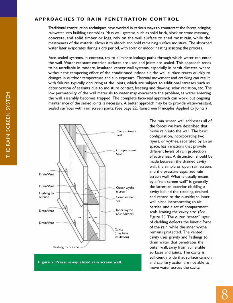
The rain screen wall addresses all ofthe forces we have described thatmove rain into the wall. The basicconfiguration, incorporating twolayers, or wythes, separated by an airspace, has variations that providedifferent levels of rain protectioneffectiveness. A distinction should bemade between the drained cavitywall, the simple or open rain screen,and the pressure-equalized rainscreen wall. What is usually meantby a “rain screen wall” is generallythe latter: an exterior cladding, acavity behind the cladding, drainedand vented to the outside; an innerwall plane incorporating an airbarrier; and a set of compartmentseals limiting the cavity size. (SeeFigure 5.) The outer “screen” layerof cladding deflects the kinetic forceof the rain, while the inner wytheremains protected. The ventedcavity uses gravity and flashings todrain water that penetrates theouter wall, away from vulnerablesurfaces and joints. The cavity issufficiently wide that surface tensionand capillary action are not able tomove water across the cavity.
TH
E R
AIN
SC
REE
N S
YST
EM
8
CompartmentSeal
CompartmentSeal
Outer wythe(screen)
CompartmentSeal
Inner wythe(Air Barrier)
Cavity(may haveinsulation)
Drain/Vent
Drain/Vent
Drain/Vent
Drain/Vent
Flashing tooutside
Figure 5. Pressure-equalized rain screen wall.
Flashing to outside

TH
E R
AIN
SC
REE
N S
YST
EM
9
Figure 6 shows in diagram form how the rain screen concept addresses air pressure differences.Exterior wind pressure (Pe) causes air to flow through the cladding vents into the cavity, increasingcavity pressure (Pc) until Pc = Pe and the pressure difference across the cladding (∆Pe) equals zero.At this point, pressure equalization has occurred, and the entire wind pressure has been transferredto the air barrier. When Pc = Pe, moisture is no longer drawn through the outer wall into the cavityby a difference in air pressure. The pressure gradient now exists between the cavity and the interiorof the building (∆Pi), but the source of water has been removed, as water is unable to cross the cavity.
Figure 7 shows the situation when the exterior wind load decreases. Now Pc > Pe and there is a netnegative load on the cladding. Air will flow outwards from the cavity until pressure equalization isagain achieved.
INTERIOREXTERIOR
P1PCPe
INTERIOREXTERIOR
P1PCPe12
Figure 6.
Figure 7.

TH
E R
AIN
SC
REE
N S
YST
EM
10
The Drained Cavity Wall
The drained cavity wall (Figure 8) has aspects of the rain screen approach and addresses someof the forces that cause rain penetration, but should not properly be called a rain screen wall.Two layers are separated by a cavity. An internal layer of free draining material installed in thecavity (the concealed barrier approach) will work in effectively the same way. The outer layerreceives the kinetic force of the rain, while the cavity or drainage layer prevents the capillary
action of water from reaching the materials ofthe inner wall. Water penetrating the outerwall must be collected and directed out ofthe cavity with flashing and weep holes. In thistype of wall, either the outer or the innerlayer may act as the air barrier to provideresistance to air leakage.
However, the major flaw in this wall design–and what prevents it from acting as a truerain screen–is its failure to address airpressure gradients. If the outer layer of thewall is most airtight, the wall surface will besubject to significant wind forces. Thelower air pressure in the cavity will createsuction, causing rainwater to infiltratethrough any tiny opening in the wall surface,whether joints, pores, gaps, cracks, or poorlybonded surfaces. Rainwater that penetratesmay exceed the volume that the wall candrain internally, or it may be retained in thewall and cause materials to deteriorate overtime.
Figure 8. Drained cavity wall
The Open (or Simple) Rain Screen
The open, or simple, rain screen wall differs from the drained cavity wall in the placement of theair barrier. Most modern cavity walls and walls clad with siding act as open rain screens. In fact, thename “rain screen” is somewhat misleading in that it implies deflecting rain is the only problem.The term “two-stage weathertightening” has been used in Europe for several decades, and is amore accurate description as it acknowledges that most water entry is controlled at the firststage, the outer wall, while air leakage is prevented at a second, inner layer.
Outer Wall
Drain
Drain
Drain
Inner Wall
Cavity(may have insulation)
Flashing to outside

TH
E R
AIN
SC
REE
N S
YST
EM
11
In this wall type the outer or “screen” layer is intentionally vented to the exterior, while the airbarrier is located at the inner layer or backup wall. Since the inner surface is the most airtight,it bears the brunt of wind pressure loads. This relieves the pressure gradient across the outerwall, which would otherwise tend to draw moisture inward. However, since the air pressuredifference now exists at the backup wall, and since some water should still be expected to passthrough the vented outer layer, the inner wall requires a second line of defense against moisture.This should be a layer of water-shedding material, such as sheathing, building paper, or a waterproofmembrane, and a flashing and drain at the base of the wall. The waterproof material should belocated on the “warm” side of the insulation to avoid condensation (for example, on the insidein cool climates with a long heating season; on the outside in climates in which indoor aircooling is a more important consideration). Note that an advantage of moving the air barrierto the inner layer is that it is often easier to seal the inner face than the outer cladding–andthe seal will last longer as it is not exposed to the exterior environment (rain, ultravioletradiation, etc.).
Common simple rain screen wall types include brick or stone veneer on concrete block backup,stucco or vinyl siding on wood or steel frame construction, etc. Wood claddings of overlappingshingles and shakes are an example from traditional construction of what is effectively a simplerainscreen wall: small air spaces exist between the lapped shingles and the backup board orstrapping to which they are fixed, with the effect of a rain screen and cavity (Figure 9). Figure 10shows a simple rain screen wall assembly incorporating brick veneer on steel stud framing. Therain screen concept can also be applied effectively to curtain walls, and the particulars of this walltype are discussed in the section,“Rain screen Principles in Curtain Wall” (page 20).
Interior finish (air barrier)
Wood stud with mineral woolinsulation
Plywood sheathing
Building paper
Vertical strapping
Exterior lapped siding (screen)
Rainscreen cavity
Air Barrier System18 mm plywood
88 mm steel studs at 400 mm o.c.
18 mm gypsum board sheathing
Brick tie mounted 400 mm aparthorizontally and vertically,mechanically fastened to steel studs
Cavity: 25 mm air space
Rain screen:100 mm clay brick
Venting in bottom row of bricks
Figure 9. Example of a simple rainscreen wall
Figure 10. A simple rain screen wallincorporating brick veneer on steel studs
2440
mm
Ove
rall
Hei
ght
X 2
440
mm
Wid
th

TH
E R
AIN
SC
REE
N S
YST
EM
12
A variation of the open rain screenpopular in Europe is the “backventilated cavity” wall (Figure 11). Thevents provided in the outer screen layerare relatively large and are concentratedat the top and bottom of the wall. Thisconfiguration takes advantage of thedifferences in air pressure (due to wind),and temperature (due to solar warming),between the base and roof of a building.The resulting airflow pattern in thecavity moves air in through the bottomvents and out the top vents, helping todry out any moisture that penetratesthe wall.
The simple rain screen wall stillprovides only limited air pressurecontrol. In principle, venting the outerwall to the exterior transfers windforces to the air barrier at the backupwall; as air flows into the cavity, thepressure in the cavity increases until itequals the applied wind pressure. Thisis referred to as pressure equalization.However, airflow through the entirewall cavity cannot respond to rapidlocal changes of pressure during gustsof wind. As wind pressures aredistributed unevenly over walls, air willalso flow laterally in the cavity toareas of low pressure at the corners and top of the building. Therefore, air pressure gradientswill still exist across the outer wall, drawing moisture inside. More control over pressuredifferences can be achieved with a pressure-equalized rain screen (PER) wall.
The Pressure Equalized Rain Screen
The Pressure-equalized rain screen wall employs additional features in the design of the cavityto improve performance over a simple rain screen wall design. Theoretically, the outer claddingof a pressure-equalized rain screen wall is not subject to any wind load, as wind forces aretransferred to the air barrier at the backup wall. This would allow design of the cladding to beas light as possible. In reality, wind forces are dynamic and variable, and pressures applied to thewall are constantly changing.
The pressure equalization strategy is sometimes referred to as “pressure modification”, as nowall system achieves immediate and constant equalization when subject to dynamic windpressures. An ideal rain screen wall would pressure equalize instantly, but research has shownthat a time lag always exists between applied wind loads and pressure equalization in thecavity. Until equalization occurs, the cladding is subject to wind pressure, requiring it toperform structurally. And as long as the pressure difference exists between the cladding andthe cavity, this force will drive moisture through the outer wall.“Time to equalization” and “peakcladding load” are therefore both measurements of the effectiveness of a PER wall.
Protected Vent
Protected Vent
Protected Vent
Drain/Vent
Drain/Vent
Drain/Vent
Inner Wall
Outer wall
Cavity (May Have Insulation
Figure 11. Back ventilated cavity wall
Flashing to outside

TH
E R
AIN
SC
REE
N S
YST
EM
13
Several parameters have been shown to affect both of these quantities. These include:
• Magnitude of the applied wind load • Airtightness of the air barrier• Leakage area of the cladding• Compartmentalization of the cavity• Cavity volume• Stiffness of the air barrier• Stiffness of the cladding
FAC TO R S A F F E C T I N G P R E S S U R E E Q UA L I Z AT I O N
Magnitude of the Applied Wind Load
Analysis of these factors has been carried out under steady-state wind pressure conditions, andso our understanding of their response to rapidly changing wind loads–gusts–is fairly speculative.Wind loading creates complex situations; for example, as the force of wind impacts a rain screenwall, airflow into the wall cavity causes the cavity air pressure to increase. The mass of air requiredto achieve equalization depends on the cavity volume, while the time to reach equalization dependson the rate at which air can enter the cavity. The pressure difference across the cladding is theforce driving air into the cavity, and the rate of air flow is proportional to the pressure difference.Therefore, the rate of air movement will decrease as air flows into the cavity and the pressuregradient diminishes. Consider, as well, that the wind loads may be varying from one second toanother, and it is clear that a very complex balance of forces is at work.
The effect of decreases in wind pressure must also be taken into consideration. In gusting windconditions, the cavity pressure will periodically exceed the outdoor air pressure. This occurs whenwind loads suddenly decrease, after the cavity pressure has increased to match that of a highwind. The higher cavity pressure will create a negative (outward) load on the rain screen, whichwill tend to force water out of openings in the cladding, providing a further defense against rainpenetration.
To take advantage of this benefit, perhaps the “ideal” rain screen wall would pressure equalizeinstantly when exposed to wind gusts, but would restrict airflow leaving the cavity to delayequalization when external wind load decreased. While such a construction might bepossible–for example, using one-way baffles on the vent openings–nothing of the sort is currentlytested or commonly used.
TH
E R
AIN
SC
REE
N S
YST
EM
14
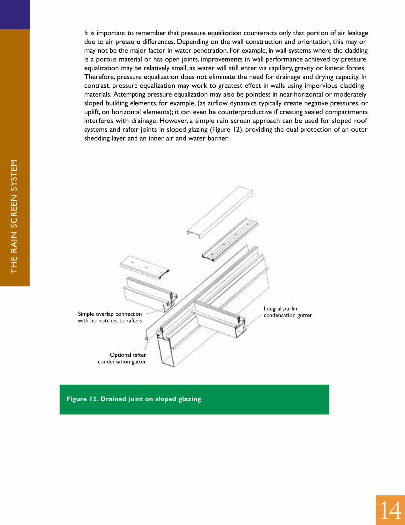
It is important to remember that pressure equalization counteracts only that portion of air leakagedue to air pressure differences. Depending on the wall construction and orientation, this may ormay not be the major factor in water penetration. For example, in wall systems where the claddingis a porous material or has open joints, improvements in wall performance achieved by pressureequalization may be relatively small, as water will still enter via capillary, gravity or kinetic forces.Therefore, pressure equalization does not eliminate the need for drainage and drying capacity. Incontrast, pressure equalization may work to greatest effect in walls using impervious claddingmaterials. Attempting pressure equalization may also be pointless in near-horizontal or moderatelysloped building elements, for example, (as airflow dynamics typically create negative pressures, oruplift, on horizontal elements); it can even be counterproductive if creating sealed compartmentsinterferes with drainage. However, a simple rain screen approach can be used for sloped roofsystems and rafter joints in sloped glazing (Figure 12), providing the dual protection of an outershedding layer and an inner air and water barrier.
Figure 12. Drained joint on sloped glazing
Simple overlap connectionwith no notches to rafters
Integral purlincondensation gutter
Optional raftercondensation gutter
TH
E R
AIN
SC
REE
N S
YST
EM
15
Airtightness of the Air Barrier
In order for wind loads to be effectively transferred to the air barrier (and in order for the airbarrier to perform its function), the air barrier must be as airtight as possible. The National BuildingCode provides recommended maximum air leakage rates for air barriers in insulated walls,ranging from 0.1 to 0.2 L/s/m2 when subject to a 75 Pa pressure difference. AAMA suggests amaximum leakage rate of 0.3 L/s/m2 at 75 Pa for curtain walls, and many walls are less airtight.For Canadian climate conditions, a rate not exceeding 0.1 L/s/m2–equivalent to a leakage areaof 10 mm2 per m2–should be the objective. Of course, performance of the air barrier has otherimplications, affecting energy utilization, condensation from exfiltration of indoor air, etc. (See theCMHC article,“Design Considerations for an Air Barrier System”.)
In addition to the actual airtightness of the air barrier, its relative airtightness with respect to thatof the cladding determines how quickly pressure equalization can be achieved. As the air barrieris made more airtight than the cladding, it will be subject to a greater pressure difference as airflows more easily across the cladding and meets more resistance at the air barrier. Ideally, the airbarrier would be completely airtight and wind loads would be entirely transferred to it, achievingcomplete pressure equalization in the cavity and zero wind load on the cladding. For practicalpurposes, complete airtightness is not possible to achieve.
Leakage Area of the Cladding
The cladding should be made less airtight than the air barrier by incorporating intentionalopenings, or vents.
The recommended area of the cladding vents is at least five times greater than the leakagearea of the air barrier. In other words, if the air barrier leaks 0.1 litres of air per second, persquare metre (the recommended maximum and equivalent to a leakage area of 10 mm2/m2), thevent area in the cladding should be at least 50 mm2 per m2. This should transfer between 80 and95% of the wind load to the air barrier; at a 10:1 ratio, the air barrier should carry 90 to 99% ofthe wind load.
The larger the vent area, the shorter the time to pressure equalization. Individual vent openingsshould be at least 8 mm in width to eliminate the possibility of capillary water bridging, and edgesshould be detailed with drips. Vents should be sloped downwards and outwards and be shieldedfrom direct exposure to the kinetic force of rain.
Some research advocates providing vents at the top and bottom of the cavity to promote dryingthrough convective air movement. Another approach recommends vents be combined withdrainage openings at the base of the cavity only, on the grounds that locating vents at differentheights in the cavity may lead to suction forces drawing moisture into the airspace. The strategyof “asymmetrical vent spacing” (see following text), in contrast, exploits the potential forpressure differences along on the cladding face to cause air movement in the cavity.

TH
E R
AIN
SC
REE
N S
YST
EM
16
Compartmentalization of the Cavity
A key aspect of PER wall design takes into account the unequal distribution of wind pressures overbuilding surfaces. Figure 3 shows how wind pressure varies over a building when the wind is at90º and 45º to one face. As the spacing of contours shows, wind pressure can be fairly uniformat the centre of walls, but steep gradients develop toward edges and at the roofline. A single wallmay experience positive wind forces in one area and negative (suction) forces elsewhere, whilecorners may be subject to strong positive pressure on one side and strong negative pressure onthe other. These pressure differences become greater as building height increases. If the cavity ofa rain screen wall has vents open to the outside in areas of unequal pressure, air will flow laterallythrough the cavity along the pressure gradient. Pressure equalization will not occur in the cavity,and the pressure difference across the rain screen can be very high–in fact, higher than if no ventswere provided–especially at the corners.
To prevent this lateral air flow, the cavity is divided into compartments. Fig. 5 shows this conceptincorporated into the rain screen system. At a minimum, the wall cavity must be sealed at all cornersof the building and at the roofline, to prevent air from the windward face being drawn through tothe negative pressure areas on the other faces. This approach should be adequate for small buildings.Corner compartment seals must be designed to resist high loads, as wind tunnel tests showthey are subject to pressures up to two or three times the structural wind load. Seals can beincorporated into other design features at corners, such as expansion joints or panel edge closures.Materials that could provide effective compartment seals include elastomeric membranes, sheetsteel angles, or foamed in urethane insulation, or extruded polystyrene cut to fit precisely andmechanically fastened. Note that compartment seals are not merely baffles, and solutions suchas fiberglass batt or glued rigid foam strips do not provide sufficient airtightness and strength.
In larger buildings, additional compartmentalization within a façade can address differences in pressureacross the building face. The size of the compartments should be based on the extent of pressurevariation across a given area. Therefore, smaller compartments are required at the edges of walls,while toward the centre of a building face, where pressure is more uniform, the compartments couldbe larger. When the concern is only rain penetration, not structural loading, only facades subject topositive wind pressures (for example, facing into the wind) need be considered. Of course, thedirection of the prevailing rain must be considered; it may not always rain from the same direction.
Determining compartment size requires a judgment by the designer as to acceptable pressurevariations over a compartment. If a building’s performance under expected wind conditions can bemodelled, compartment spacing can be calculated based on parameters set by the designer. Forexample, one might decide that the variation in wind pressure across the face of a compartmentshould be less than 10% of the maximum wind pressure on that compartment area. Such arestriction might, however, demand very small compartment sizes at building extremities. A bettersolution might be to detail corners to require less pressure equalization–through increaseddurability, a sealed waterproof membrane, good drainage, etc.
Some basic principles can be used to size compartments in the absence of calculations based onspecific wind loads. Assuming vents in the cladding are evenly spaced, compartments located closeto the edges (within 10% of the building’s width) should be small, around 1-1.2 m wide. The samedimensions apply to the height of compartments located within 10% of building height from theroofline. For the rest of the building, compartments could be up to 10-15 m wide and one or twostoreys high (up to around 6 m). Flashing and drainage are required at horizontal compartmentdivisions (the vent openings at the base of each cavity can serve the drainage function).

TH
E R
AIN
SC
REE
N S
YST
EM
17
A 1995 CMHC study (Reference 7) provides more detailed recommendations on compartmentsizing, shown in Table 1. These recommended dimensions are more conservative than the aboveand are intended to provide pressure equalization–within 25 Pa–under instantaneous gustingwind pressures, which can be significantly higher than average maximum wind loads. Since rainpenetration control has more to do with average, cumulative moisture penetration than singleor momentary events–unlike load calculations for structural design–to determine whether thecavity warrants design to gust pressure levels, the designer must consider various factors, suchas: local wind behaviour and exposure of the building to gusts; vulnerability of the wall materialsto moisture damage with limited wetting; etc.
Compartment Sizeas % of Building Width (w) and Height (h)
Region of Building Width Height
3%* to 10% of width from corner 2% w or 1m 5% h or 1m
10% to 20% of width from corner 4% w or 1m 5% h or 1m
20% to 50% of width from corner 8% w or 1m 10% w or 1m
3% to 10% of height from top 5% w or 1m 2% h or 1m
10% to 20% of height from top 5% w or 1m 4% h or 1m
20% to 100% of height from top 10% w or 1m 8% h or 1m
Table 1. Design guidelines for compartment sizing to achieve gust pressure equalization
* The study states that pressure equalization is unlikely to be achieved in the 3% of buildingwidth and height closest to the edges.
(From “A Study of the Characteristic Shapes of Mean Pressures and Their Gradients on Buildings in Realistic Surroundings.”P.F. Skerlj and D. Surry for CMHC, 1995.)
When the cavity is compartmentalized to achieve pressure equalization, additional vent areashould be provided to compensate for air leakage through compartment seals. Corner seals areespecially subject to high pressure differences. Therefore, in addition to providing five times theair barrier leakage area as noted above, effective vent area for a compartment should include 10times the estimated leakage area of corner seals, and once the estimated leakage area of anyintermediate compartment seals.
18
TH
E R
AIN
SC
REE
N S
YST
EM
Compartments may be made wider if vent position is adjusted to take advantage of the steeppressure gradients at the building edges. Instead of spacing vents evenly across the face of acompartment, vents are concentrated in areas of highest wind pressure. Rather than pressureequalization, this approach employs a positive pressurization of the cavity. Providing thecompartment is well sealed and the vent is the major area of air leakage in the cladding (for example,the leakage of the cladding material is small compared to the vents), cavity pressure will rise tomatch the wind pressure at the vents. This will create an outward pressure on the cladding overmost of the compartment width, which will drive water out of leakage paths rather than in. Thewider the compartment (and the larger the pressure variations over the cladding face), the higherthe resulting outward pressure difference. As a rule, vents should be placed at the edge of thecompartment closest to the centre (where wind pressures are highest on a windward face).This area remains insufficiently researched, but this approach seems viable with compartments10% of façade width or larger. Note that asymmetrical vent spacing in very wide or highcompartments may increase structural loads due to the pressure differences created, and thispossibility should be taken into consideration. This venting strategy could create inward forceswhen the façade is subject to significant negative pressures–that is when wind direction makes it aleeward face–but in this case the wall would be protected from rain. The virtue of asymmetricvent spacing is that it should work to protect precisely those areas of the building that aremost exposed to rain-wetting. In fact, wind tunnel testing of this vent strategy has shown nearzero or outward pressures across the cladding at the roofline and edges, areas of heaviestrain-wetting.
Asymmetrical vent spacing relies on the fact that it is the location of the vents that connectthe sealed compartment to the outside, and the specific air pressures at those locations, thatdetermine the air pressure in the entire enclosed compartment. Care must be taken to use thisstrategy effectively, as common construction practices may compromise its effectiveness. (Forexample, using snap caps over curtainwall joints may cover the vent openings for the glazingcavities and spandrel sections; see page 20,“Rain screen Principles in Curtain Wall”.) As well, forthe most part, vents should not be located on protrusions from the face of the building, as windflow around protrusions may create local suction pressures which would act against compartmentpressure equalization. For this reason, cladding vents should not be located close to the buildingedges, though drainage should be provided at extremities.
Cavity Volume
As mentioned above, gusting or cyclic wind pressures create complex conditions for achievingpressure equalization. Walls can experience air pressures due to gusting winds that are morethan double the average or mean wind pressures. While the influence of the relative airtightnessof the cladding and the air barrier on achieving pressure equalization was explained, the volume ofthe air cavity is also a factor in this equation. If the cavity is large, more air must move throughthe vents to achieve equalization. Therefore cavity volume, as well as the leakiness of the airbarrier, determines the vent area required in the cladding.
Minimum cavity volume is governed by minimum cavity width. A minimum cavity width is required,sufficient to provide a capillary break, permit drainage of any water that enters the cavity, andallow unobstructed air movement (including convective air movement to enhance drying, if ventsare provided at top and bottom of the cavity). A cavity width of about 25 mm is suitable–andremember to make allowances for construction tolerances.
In determining maximum cavity volume, tests carried out by the National Research Council ofCanada [INSERT REFERENCE] showed that the ratio of cavity volume to vent area should beless than 50 m3 to 1 m2 for a PER wall with rigid components (the wall tested was a precastconcrete panel system).
TH
E R
AIN
SC
REE
N S
YST
EM
19
Stiffness of the Air Barrier and Cladding
The stiffness of the cladding and of the air barrier must also be considered, as their deflection underwind loads affects the working volume of the cavity. Increasing the flexibility of the cladding reduceswind pressure loads on the cladding, but will affect cavity volume. Increasing the flexibility of theair barrier, in contrast, will increase wind loads on the cladding, as these pressures will not betransferred to the air barrier as quickly. Variations in cavity volume resulting from deflection ofthe cladding or air barrier may promote suction of wind and rain into the cavity, which isundesirable. A constant cavity volume helps the cavity respond faster to rapid changes in appliedwind pressure. Rigidity of the air barrier is also desirable as it maintains a uniform distribution ofloads, rather than causing stress at the supports. The more flexible the assembly, the morevariable the cavity volume, and the lower the ratio of cavity volume to vent area should be. Forexample, a somewhat flexible assembly, such as brick veneer, requires a ratio of 25:1 or lower.
M O D E L L I N G C Y C L I C W I N D P R E S S U R E S
CMHC has developed a software program, RainScreen 2.0, which can model a wall assembly’sperformance under cyclic wind pressures. The user provides input on wind loading (mean andpeak pressures, and gust frequency), cavity dimensions, cladding vent area and flexibility, and airbarrier leakage and flexibility. The program estimates static and cyclic loads carried by the rainscreen cladding and models how cavity pressure responds (in magnitude and time) to changes inwind pressure. The software can thus show the impact of varying any of the design parameters–for example, how increasing cavity volume slows time to pressure equalization, while increasingvent area speeds it. The effects of varying the flexibility of the cladding or the air barrier canalso be seen.
REDUCED CLADDING LOADS DUE TO PRESSURE EQUALIZATION
In theory, if wind pressure across the rain screen can be controlled at all times, so can the structuralload on the cladding. Future wall assemblies, some currently being developed by manufacturers,may take advantage of pressure equalization to allow lighter cladding panels. Here, however, theinstantaneous peak loads presented by gusting winds are the limiting factor: structure must bedesigned for these loads, while water penetration control is more concerned with averagepressure differences. Tests have shown that rapid changes in wind loading, such as produced bygusting winds, result in higher loads on the cladding. While a basic understanding of the factorsaffecting peak cladding load exists, any reduction of structural capacity in the cladding and itsanchors would have to be certain of cladding behaviour in all conditions. The National BuildingCode requires that cladding elements be designed to the 10-year maximum wind pressures fortheir location and assuming a gust factor of 2.5. Some researchers have suggested a target of 25%of peak wind pressure being carried by rain screen cladding, but there is currently little scope forassuming reduced structural loads in the design of rain screen cladding systems. An exceptioncould be instances where cladding load limits are based on serviceable criteria such asappearance, noise, or non-catastrophic deterioration.

TH
E R
AIN
SC
REE
N S
YST
EM
20
R A I N S C R E E N P R I N C I P L E S I N
C U RTA I N WA L L S
Figure 13 shows a curtain wall detailed asa partial rain screen. The rain screenconcept can be applied to curtain wall, tocreate a wall assembly that is essentially acombination of a face-sealed system (theglazing unit), portions of rain screen wall(the spandrel panels), and a set of rainscreen joints. The wall section shows howthe spandrel works as a rain screen wall.The glass spandrel panel is the cladding, andthe cavity is between the panel and themetal backpan. The air barrier incorporatesthe back of the sealed glazing unit, theshoulder of the sill mullion, the backpan,the shoulder of the header mullion, theback of the next glazing unit, and so on.Seals are required to maintain air barriercontinuity, typically wet sealant (glazingtape) or a gasket between the window faceand the mullion shoulder, and glazing tapeor sealant at the joint between thebackpan and the mullion.
Many curtain walls work effectively withdrained cavities only, but designing forpressure equalization requires additionalconsiderations. Remember that in assessingmaximum cavity volume, the ratio of cavity volume to vent area should be less than 50 m3 to 1m2 for a PER wall with rigid components, while a more flexible assembly requires a lower ratio.Here, the sheet metal backpan acting as the air barrier at the spandrel panels would typicallybe relatively flexible, perhaps 20 or 22 gauge sheet metal. Especially given the large volume ofthe airspace at the spandrel panel (compared to the window panels), this could significantlydecrease the potential for pressure equalization.
For the rain screen to function, deflection limits should be established in consideration of cavityvolume, especially for larger panels. The larger the spandrel area, the larger the potential changein cavity volume caused by deflection of the backpan. Since vent area is provided at the mullionsand will not usually be significantly adjusted for different panel sizes, deflection limits shouldperhaps be proportionately less for larger panels than for smaller areas. In conventionalconstruction, the backpan may be backed with rigid insulation or provided with metal stiffeners,but limiting deflection is usually not considered except with respect to noise or firestoppingissues. In this case, if 100 mm foam insulation is used instead of fiberglass batt, this will reducethe volume of the airspace significantly and help to stiffen the backpan. A cavity-volume-to-vent-area ratio of around 25:1 should be acceptable. Vents should be provided at the bottom, or attop and bottom of the cavity, through slots in the pressure plate as shown. Vents along the sideare impractical as they would be under the vertical mullion cap.
Figure 13. Rain screen concept applied to acurtain wall
Note: Air chambers surrounding glass and panelsare open to outside along their lower edges only.
Spandrel Glass (Screen)
Spandrel Backpan (A.B.)
P.E. Air Chamber
Gasket
SlottedOpenings(Vents)
Air Seal(Barrier)
P.E. Air Chambers(Cavity)
Line of Air Barrier

TH
E R
AIN
SC
REE
N S
YST
EM
21
Cavity compartmentalization must be taken into account. The glazing splines at the necks ofmullions provide a good separation, except for two air leakage paths: the intersection ofhorizontal and vertical mullions, and the gap between the pressure plate and the mullion. Cornerblocks can be sealed to the mullions to address the first problem (see Figure 14). A compressiblethermal break can act as a gasket between the pressure plate and spline, to solve the secondproblem.
Snap caps used over curtainwall joints are apotential concern, as these may cover the ventopenings for the glazing cavities and spandrelsections. The snap caps thus create another,continuous cavity into which the pressureequalization vents open. We noted thatasymmetrical vent spacing relies on thelocation of the vents that connect thesealed compartment to the outside, and thespecific air pressures at those locations, thatdetermine the air pressure in the entireenclosed compartment. The locations of thedrainage and venting openings of the snap capsthus determine the effective locations of thepressure equalization vents on the wall face.These locations may be less than ideal–forexample, at negative pressure areas–and willimpede the rain screen performance. As well,the openings in the snap caps must be at leastas large as the vent open area, otherwiseeffective vent area is reduced– twice the area is
recommended. Compartmentalizing the snap cap cavities can be achieved if horizontal caps areinterrupted at mullion intersections and vertical snap caps are continuous (and no vents areunder the vertical caps). This will effectively restrict the snap cap cavities to the size of theglazing or spandrel panel.
To take advantage of asymmetrical vent spacing, the design could specify, for example, a 50-mmdrain slot, located 50 mm from the vertical mullion at one edge, with 10-mm drain holes providedat the centre and the other side of the compartment.
Figure 14. Corner block
Sealant requiredat inteior gasketintersection
Sealant required atframing memberintersection
Sealant required at corner blockto framing member intersection
Corner Block
TH
E R
AIN
SC
REE
N S
YST
EM
22
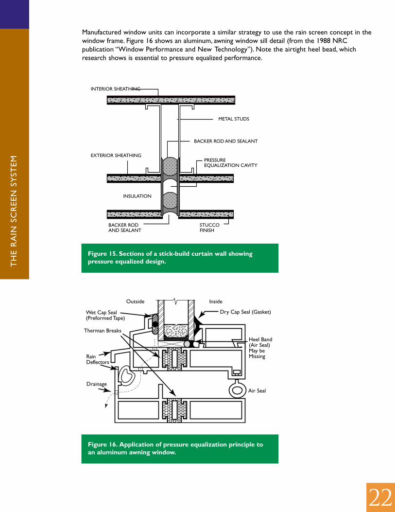
Manufactured window units can incorporate a similar strategy to use the rain screen concept in thewindow frame. Figure 16 shows an aluminum, awning window sill detail (from the 1988 NRCpublication “Window Performance and New Technology”). Note the airtight heel bead, whichresearch shows is essential to pressure equalized performance.
InsideOutside
Therman Breaks
RainDeflectors
Drainage
Dry Cap Seal (Gasket)Wet Cap Seal(Preformed Tape)
Air Seal
Heel Band(Air Seal)May beMissing
Figure 16. Application of pressure equalization principle toan aluminum awning window.
INSULATION
STUCCO FINISH
BACKER ROD AND SEALANT
EXTERIOR SHEATHING
INTERIOR SHEATHING
METAL STUDS
BACKER ROD AND SEALANT
PRESSUREEQUALIZATION CAVITY
Figure 15. Sections of a stick-build curtain wall showingpressure equalized design.

TH
E R
AIN
SC
REE
N S
YST
EM
23
R A I N S C R E E N P R I N C I P L E S A P P L I E D TO J O I N T S
Joints are typically the most vulnerable point of water entry in all kinds of wall construction, dueto differential movement, sealant deterioration, etc. Rain screen principles can be applied to jointswhether the wall is itself a rains creen, or a face-sealed assembly, such as EIFS or precast panels.A rain screen joint incorporates the same elements as a rain screen wall:
1. A cavity which is drained and vented to the outside2. An outer weather seal3. An inner seal which is the primary air seal (the air barrier)
And the same considerations apply to detailing the rain screen joint:
• The inner seal should be water-resistant to provide a second line of defense against moisture• The outer seal should have a vent area equal to at least five times the leakage area of the
inner air seal• The cavity should be compartmentalized, especially near edges of the building.
A ratio of 5:1 or 10:1 between vent area and air seal leakage should be adequate to achievepressure equalization even during gusting winds, as the cavity volume of most joints is small.
A 1995 CMHC study of EIFS panel joints (Measured Pressure Equalized Performance of TwoPrecast Concrete Panels, Performance of Pressure Equalized Rainscreen Walls) showed thatrain screen joints performed much better than face-sealed and recessed joint designs inpreventing moisture penetration. Figure 17 shows an example of a two-stage EIFS panel jointfunctioning as a rain screen. Note that the outer seal must be open and drained at the base ofthe panel, with flashing provided along the horizontal joint.
Figure 17. Example of a two-Stage EIFS panel joint.
10 MIN.FLASHING
EFFECTIVEUPSTAND
BAFFLE
2"DRAINAGE
ZONE
AIR SEALSINTERSECT
Backer Rod
Caulking
Drain Vent
Figure 18. Example of a two-stage precast panel joint.

TH
E R
AIN
SC
REE
N S
YST
EM
24
W H E N TO U S E A R A I N S C R E E N WA L L
Rain screen walls have become the most reliable choice for applications exposed to significant rainand wind. As we have seen, a fully pressure equalized rain screen wall incorporates several strategiesfor minimizing rain penetration: rain shedding by the cladding; drainage and venting to speedremoval of water that passes through the rain screen; air pressure equalization in the cavity tominimize forces drawing water through the cladding, with the cavity also providing a capillarybreak; and a second layer of moisture protection at the backup wall.
The greater care required in detailing and construction to achieve a pressure-equalized rain screenwall or joint may add complexity and expense compared to other wall systems. However,because a major driving force of water entry is reduced, a PER wall is more tolerant of commonconstruction defects and should require less maintenance over its service life. This wall system is,therefore, probably the most conservative approach for the most severe applications. However, arain screen wall is not necessarily the best solution in every instance. In some climates and someapplications, face-sealed walls perform well, and rain screen construction might be unsuitable dueto expense, space, structural considerations or other factors.
As well, there are types of wall construction with proven durability that incorporate features ofthe simple rain screen and are worth considering in less demanding applications. For example:
• Walls incorporating only materials which are not subject to moisture damage ordeterioration.
• Combining solid panels of a relatively impervious material, such as concrete, with rain screenjoints to seal between them (using a face-sealed strategy for most of the wall, with rain screenjoints).
• Using an air barrier made of a very impermeable, tough and well-sealed material (such as awaterproof membrane), and using only materials not subject to moisture damage outside ofthis layer. Note that the membrane must be located on the warm side of most insulation toprevent condensation at its surface.
• Walls clad in impervious materials, with joints protected from direct or capillary water entry,provided with careful flashing and venting to promote draining and drying, and with a goodsecond line of defense against moisture entry.
• Any of the above, designed to achieve partial pressure equalization by compartmentalizingvents at corners, and to the extent it is practical, in the façade.

TH
E R
AIN
SC
REE
N S
YST
EM
25
PERFORMANCE STANDARDS FOR RAIN SCREEN WALLS
There are no universally adopted standards in Canada for measuring performance of a rain screenwall. If a wall system is to be designed and built to performance criteria, however, the design andbuilding process must be expanded to include engineering and commissioning procedures toverify design levels and construction compliance. Recent studies commissioned by CMHC havelooked at establishing quantitative criteria and developing field tests of rain screen performance.(See References 4 and 5:“Testing Rain screen Wall and Window Systems: The Cavity ExcitationMethod” and “The Rain screen Wall: A Commissioning Protocol”.) These studies propose aminimum of 80% pressure equalization at steady wind pressure and 50% under dynamic conditionsas provisional performance standards. Criteria would ideally also include an allowable ratio of rainpenetration to rain loading, but establishing this standard requires further research.
Performance criteria should be established before envelope detailing. A modelling tool such asCMHC’s RainScreen 2.0 should be used during the design process to analyze and refine iterationsof the envelope design until the above criteria are achieved. Working drawings and specificationscould then follow. The design would be validated before construction with tests of a mockupbuilt to drawings and specifications. Testing would ideally be in a laboratory, or else a mockupcould be built on site as part of the construction contract with some budget allowance forredesign. Research commissioned by CMHC has developed a test method, the “Cavity ExcitationMethod” (CEM), suitable for laboratory and field testing. The rain screen cavity is subjected tovarious levels of air pressure (positive and negative) and flow (steady state and dynamic) to obtainbasic leakage data. The measured rate of pressure change in the cavity is also an indicator ofperformance, reflecting the combined effect of attributes such as cavity volume, flexibility ofcomponents, and leakage and vent area.
Upon construction, attributes to be measured for compliance could include the following: leakagearea of air barrier and compartment seals not exceeding a specified maximum; rain screen ventarea not less than a specified minimum; and deflection of the cladding and air barrier withinspecified limits. A water test comparable to ASTM E547,“Standard Test Method for WaterPenetration of Exterior Windows, Skylights, Doors, and Curtain Walls by Cyclic Static AirPressure Difference”, is also recommended to test for control of kinetic, capillary and gravityforces, to ensure that water in the cavity is not excessive, and that no water infiltrates thebuilding interior.
TH
E R
AIN
SC
REE
N S
YST
EM
26
REVIEW: CHECKLIST OF 10 CRITICAL POINTS IN RAIN SCREEN DETAILS
In summary, to achieve rain penetration control, an effective rain screen wall depends oncertain key features. These are:
• Provision for water shedding at the outer cladding, away from joints, with drips under anyprojections to prevent water collecting at the building face.
• A cavity of appropriate width to allow pressure equalization across the cladding system andprevent capillary movement (allow for construction tolerances!).
• A continuous and effective (for example, airtight to a maximum air leakage of 0.1 L/s/m2)air barrier within the backup wall.
• Drainage of the cavity through continuous flashings and weep openings, and propermanagement of drained water.
• Adequate venting of the cavity provided through properly located openings in the cladding(appropriate ratio achieved between vent area and leakage of air barrier and seals).
• Additional provision for drainage at the backup wall (located on the “warm” side of theinsulation to avoid condensation problems).
• Effective compartmentalization of the cavity at each building face with airtight seals, andadditionally across the width of the façade as required (refer to calculations).
• Sufficient rigidity and/or structural support of the air barrier to resist wind loads and limitdeflection.
• Sufficient rigidity of the cladding to limit deflection and resist wind loads as required.
• Special attention paid to water-resistance and drainage at building edges and parapets (areassubject to heaviest rain-wetting and wind pressure differences, where pressure equalizationmay not be achievable).

TH
E R
AIN
SC
REE
N S
YST
EM
27
QUESTIONS
1. What areas of a wall are subject to heaviest rain-wetting?
2. Why should a wall cavity be compartmentalized?
3. What must be considered in determining cavity width when designing a rain screen wall?
4. Is a PER suitable for a near-horizontal or low-sloped surface?
5. If a wall is designed as a PER, the cladding does not have to be designed to resist wind loads…True or false?
6. In a curtain wall system designed as a PER, why should care be exercised when using snap capson the mullions?
7. A wall consists of brick veneer on concrete block backup, with a 25 mm airspace and semi-rigidinsulation. If the brick incorporates sufficient vents to achieve pressure equalization in thecavity, no other measures are required to prevent rain from penetrating the wall … Trueor false?
8. A rain screen wall assembly employs interior gypsum board as the air barrier, with an airleakage rate of 0.02 L/s/m2. How much open vent area should be provided in the cladding,per m2?
9. Now assume the wall cavity is compartmentalized to improve pressure equalization. A singlecompartment at the edge of the building and halfway up the building face is 3 m high x 1.2 mwide. The compartment is closed along the outside edge and on the other three sides,leaving an opening of 0.1 mm (average). What is the leakage area of the compartment seals?How much vent area does the compartment require?
10. The west facade of a six-storey building faces prevailing winds and is 21 m high x 36 m wide.The wall is a PER incorporating masonry veneer cladding. Suggest a compartmentalizationplan for the wall cavity to enhance pressure equalization.
For the answers to these questions, please refer to your professionalassociation’s Web page.

TH
E R
AIN
SC
REE
N S
YST
EM
28
R E F E R E N C E S
1. “Rain Penetration Control: Applying Current Knowledge”, Morrison Hershfield Limited, 2001.
2. “Pressure-Equalized Rainscreen Walls”, Luis de Miguel for Canada Mortgage and HousingCorporation, 1998.
3. “Laboratory Investigation and Field Monitoring of Pressure Equalized Rain screen Walls”,Quirouette Building Specialists Ltd. for CMHC, 1996.
4. “Testing Rainscreen Wall and Window Systems: The Cavity Excitation Method”, QuirouetteBuilding Specialists Ltd. for CMHC, 1996.
5. “The Rainscreen Wall: A Commissioning Protocol”, Quirouette Building Specialists Ltd. forCMHC, 1996.
6. “Simulation of Wind-Driven Rain and Wetting Patterns on Buildings”, D. Inculet and D. Surry forCMHC, 1995.
7. “A Study of the Characteristic Shapes of Mean Pressures and Their Gradients on Buildings inRealistic Surroundings”, P.F. Skerlj and D. Surry for CMHC, 1995.
8. “Measured Pressure Equalized Performance of Two Precast Concrete Panels, Performanceof Pressure Equalized Rainscreen Walls.” William C. Brown, , W. Alan Dalgliesh, James M.Ullett, A Collaborative Research and Development Project for the National ResearchCouncil Canada, Ottawa, 1995.
9. Exterior Insulation Finish Systems, Laboratory Evaluation of Materials and Joints Subject toArtificial Conditioning, Gibson, Lawrence,Canada Mortgage and Housing Corporation,Ottawa, 1995.
10. “The Rainscreen Wall”, Dale D. Kerr, Progressive Architect August, 1990.
11. “Facts and Fictions of Rain-Screen Walls”, M.Z. Rousseau, Construction Canada 32(2), 1990.
C R E D I T S
Photo page 2: Canadian Precast/Prestressed Concrete Institute