Embed Size (px)
Citation preview
Systems Engineering
T MU AM 06006 GU
Guide
Version 2.0
Issued date: 09 March 2018
© State of NSW through Transport for NSW 2018

T MU AM 06006 GU Systems Engineering
Version 2.0 Issued date: 09 March 2018
Important message
This document is one of a set of standards developed solely and specifically for use on Transport Assets (as defined in the Asset Standards Authority Charter). It is not suitable for any other purpose. The copyright and any other intellectual property in this document will at all times remain the property of the State of New South Wales (Transport for NSW). You must not use or adapt this document or rely upon it in any way unless you are providing products or services to a NSW Government agency and that agency has expressly authorised you in writing to do so. If this document forms part of a contract with, or is a condition of approval by a NSW Government agency, use of the document is subject to the terms of the contract or approval. To be clear, the content of this document is not licensed under any Creative Commons Licence. This document may contain third party material. The inclusion of third party material is for illustrative purposes only and does not represent an endorsement by NSW Government of any third party product or service. If you use this document or rely upon it without authorisation under these terms, the State of New South Wales (including Transport for NSW) and its personnel does not accept any liability to you or any other person for any loss, damage, costs and expenses that you or anyone else may suffer or incur from your use and reliance on the content contained in this document. Users should exercise their own skill and care in the use of the document. This document may not be current and is uncontrolled when printed or downloaded. Standards may be accessed from the Asset Standards Authority website at www.asa.transport.nsw.gov.au
© State of NSW through Transport for NSW 2018

T MU AM 06006 GU Systems Engineering
Version 2.0 Issued date: 09 March 2018
Standard governance
Owner: Manager Systems Engineering Process, Asset Standards Authority
Authoriser: Director Network and Asset Strategy, Asset Standards Authority
Approver: Executive Director, Asset Standards Authority on behalf of the ASA Configuration Control Board
Document history
Version Summary of changes
1.0 First issued 05 May 2015
2.0 Second issue. Changes from the previous version include: • inclusion of 'demand/need' stage in TfNSW asset life cycle • removal of references to specific TfNSW divisions • change focus from heavy rail to multi-mode
For queries regarding this document, please email the ASA at [email protected] or visit www.asa.transport.nsw.gov.au
© State of NSW through Transport for NSW 2018
T MU AM 06006 GU Systems Engineering
Version 2.0 Issued date: 09 March 2018
Preface The Asset Standards Authority (ASA) is a key strategic branch of Transport for NSW (TfNSW).
As the network design and standards authority for NSW Transport Assets, as specified in the
ASA Charter, the ASA identifies, selects, develops, publishes, maintains and controls a suite of
requirements documents on behalf of TfNSW, the asset owner.
The ASA deploys TfNSW requirements for asset and safety assurance by creating and
managing TfNSW's governance models, documents and processes. To achieve this, the ASA
focuses on four primary tasks:
• publishing and managing TfNSW's process and requirements documents including TfNSW
plans, standards, manuals and guides
• deploying TfNSW's Authorised Engineering Organisation (AEO) framework
• continuously improving TfNSW’s Asset Management Framework
• collaborating with the Transport cluster and industry through open engagement
The AEO framework authorises engineering organisations to supply and provide asset related
products and services to TfNSW. It works to assure the safety, quality and fitness for purpose of
those products and services over the asset's whole-of-life. AEOs are expected to demonstrate
how they have applied the requirements of ASA documents, including TfNSW plans, standards
and guides, when delivering assets and related services for TfNSW.
Compliance with ASA requirements by itself is not sufficient to ensure satisfactory outcomes for
NSW Transport Assets. The ASA expects that professional judgement be used by competent
personnel when using ASA requirements to produce those outcomes.
About this document
This document provides guidance in complying with the requirements stated in
T MU AM 06006 ST Systems Engineering standard.
This guide is a second issue.
This guide is revised to include the demand/need stage in TfNSW asset life cycle and modify
the contents to change the focus from heavy rail to multi-mode.
© State of NSW through Transport for NSW 2018 Page 4 of 76
T MU AM 06006 GU Systems Engineering
Version 2.0 Issued date: 09 March 2018
Table of contents 1. Introduction .............................................................................................................................................. 7
2. Purpose .................................................................................................................................................... 7 2.1. Scope ..................................................................................................................................................... 8 2.2. Application ............................................................................................................................................. 8
3. Reference documents ............................................................................................................................. 9
4. Terms and definitions ........................................................................................................................... 10
5. Introduction to systems engineering .................................................................................................. 13 5.1. Systems engineering approach ........................................................................................................... 13 5.2. Benefits of systems engineering .......................................................................................................... 14 5.3. Possible outcomes of not using systems engineering ......................................................................... 15 5.4. Practical application of systems engineering ....................................................................................... 15 5.5. Scaling and tailoring SE effort ............................................................................................................. 16
6. SE context within enterprise management ......................................................................................... 17
7. System overview.................................................................................................................................... 17 7.1. Stakeholder viewpoints ........................................................................................................................ 19 7.2. Requirements hierarchy and structure ................................................................................................ 22 7.3. Concept of operations .......................................................................................................................... 24 7.4. Operations concept .............................................................................................................................. 24 7.5. Maintenance concept ........................................................................................................................... 25 7.6. Functional architecture ........................................................................................................................ 26 7.7. Physical solution architecture .............................................................................................................. 29 7.8. Geographic deployment architecture ................................................................................................... 30 7.9. Interface architecture ........................................................................................................................... 32 7.10. Interim system migration states ....................................................................................................... 32
8. System life cycle description ............................................................................................................... 33 8.1. Integrated system life cycle ................................................................................................................. 36 8.2. System life cycle phases ..................................................................................................................... 37
9. Systems engineering organisation structure ..................................................................................... 41 9.1. Systems engineering roles and responsibilities................................................................................... 42 9.2. Project organisation ............................................................................................................................. 45 9.3. RACI Matrix.......................................................................................................................................... 46
10. Systems engineering shared information ........................................................................................... 47
11. Systems engineering management plan ............................................................................................. 48 11.1. Need for a SEMP ............................................................................................................................. 49 11.2. SEMP and concept phase ............................................................................................................... 49 11.3. Systems engineering deliverables ................................................................................................... 49 11.4. SEMP content .................................................................................................................................. 50 11.5. SEMP context .................................................................................................................................. 51
12. Systems engineering technical processes ......................................................................................... 53 © State of NSW through Transport for NSW 2018 Page 5 of 76
T MU AM 06006 GU Systems Engineering
Version 2.0 Issued date: 09 March 2018
12.1. Requirements definition process ..................................................................................................... 53 12.2. Requirements analysis process ....................................................................................................... 55 12.3. System architectural design process ............................................................................................... 56 12.4. Implementation process ................................................................................................................... 57 12.5. Interface and integration process .................................................................................................... 57 12.6. Verification and validation process .................................................................................................. 59 12.7. Transition process ........................................................................................................................... 61 12.8. Operation process ........................................................................................................................... 61 12.9. Maintenance process ....................................................................................................................... 62 12.10. Disposal process ............................................................................................................................. 62 12.11. Process mapping to the life cycle .................................................................................................... 62
13. Technical specialty processes ............................................................................................................. 63 13.1. EMC management ........................................................................................................................... 63 13.2. RAMS management ........................................................................................................................ 64 13.3. HFI management ............................................................................................................................. 66
14. Related life cycle processes ................................................................................................................. 66 14.1. Agreement processes ...................................................................................................................... 66 14.2. Organisational project-enabling processes ..................................................................................... 67 14.3. Project processes ............................................................................................................................ 67 14.4. Tailoring processes .......................................................................................................................... 68
15. SE tools .................................................................................................................................................. 68
Appendix A Example of SEMP structure .............................................................................................. 69 A.1. SEMP structure .................................................................................................................................... 69
Appendix B Examples of SE application effort and scaling............................................................... 71
Appendix C Specific and generic system life cycles .......................................................................... 72
Appendix D Example of a light rail system .......................................................................................... 74
Appendix E TfNSW asset classification scheme ................................................................................ 75
Appendix F Example of interface control document matrix .................................................................. 76
© State of NSW through Transport for NSW 2018 Page 6 of 76

T MU AM 06006 GU Systems Engineering
Version 2.0 Issued date: 09 March 2018
1. Introduction Transport for NSW (TfNSW) has adopted a total asset management approach to the planning,
acquisition, operation, maintenance and disposal of TfNSW transport systems and assets to
support the transport services provided to the people of New South Wales. Systems
engineering (SE) is the engineering methodology that supports the asset management.
The contents of this guide are intended to assist the reader in applying the requirements stated
in T MU AM 06006 ST Systems Engineering.
SE is placed within the context of enterprise management arrangements. The need to define
the system overview from different perspectives is identified.
This document also describes the system life cycle and all stages from both an international
standard (AS/NZS ISO/IEC/IEEE 15288:2015 Systems and software engineering - System life
cycle processes) perspective and the TfNSW asset life cycle perspective. The need for, and
structure of a systems engineering management plan (SEMP) is identified, along with its context
to other relevant plans.
The SE general technical processes, specialty processes and related lifecycle processes are
identified and explained.
2. Purpose The purpose of this document is to provide guidance on complying with the mandatory
requirements of T MU AM 06006 ST.
The benefit of SE as a methodology to project managers in planning and delivering new or
altered systems is to mitigate against risks, including poor quality, inadequate performance, cost
overrun, schedule overrun and lack of acceptance by the client.
The objective of this SE guide is to develop a structured, repeatable and scalable approach for
carrying out SE on transport projects ranging from simple to complex.
The initial objective is to develop this SE guide to support refocusing and revitalising existing
transport projects experiencing issues in applying systems engineering. The capability maturity
in SE across a spectrum of engineering organisations applying for Authorised Engineering
Organisation (AEO) status ranges from very low or emerging awareness, to very high
sophisticated application in the transport and other industry sectors. The purpose of this SE
guide is to assist AEOs with emerging capability maturity to better understand the need for SE,
and practical application of SE on projects that may range from simple to complex.
Much of the information, principles and methods in this SE guide may not be new to SE
practitioners and AEOs with a high capability maturity in SE application.
© State of NSW through Transport for NSW 2018 Page 7 of 76
T MU AM 06006 GU Systems Engineering
Version 2.0 Issued date: 09 March 2018
2.1. Scope The SE guide sets out the structure and practice for carrying out SE activities associated with
planning, acquisition, development, utilisation and disposal of new or altered transport systems.
This guide should be read in conjunction with AS/NZS ISO/IEC/IEEE 15288:2015, the INCOSE
Systems Engineering Handbook, and T MU AM 06006 ST Systems Engineering.
This guide does not cover asset or discipline-specific (for example, signalling, civil, track or
electrical) design methods, tools and processes, and is focused at the integrated transport
system perspective.
2.2. Application SE is a methodology for engineering complex integrated systems and should not be considered
as a separate department, discipline or role.
All key stakeholders across the asset or system life cycle should be using or engaging in the SE
process rather than seeing it as the responsibility of a specific project role.
The user of this guide should understand how to apply SE principles, scaled to the appropriate
level in a practical and cost-effective manner. This is no different from quality, safety or project
management.
This guide applies to the following:
• all entities within TfNSW and the supply chain involved in the planning, acquiring,
operating, maintenance and disposal of new or altered systems
• portfolio, program and project directors, project managers, systems engineering managers
and engineering design managers
• planning and execution of SE activities on TfNSW engineering projects, and across the full
system life cycle from concept to disposal
• AEOs in the supply chain involved in the planning, acquiring, operating, maintenance and
disposal of new or altered transport systems
The users of this guide should understand and apply the relevant systems engineering
management activities described in this document. The concepts, principles and processes
described in this SE guide should be tailored and scaled to suit the level of novelty, complexity,
scale and risk on each project.
Not every element of this SE guide is relevant or should be applied on every project. Relatively
simple track renewal, wharf resurfacing, bust stop replacement, overhead wiring (OHW), bus
depot office refurbishment or minor junction remodelling projects may require a minimal level of
SE application, whereas highly complex, novel network-wide programs such as bus fleet
procurement may require SE application of most elements of this guide. © State of NSW through Transport for NSW 2018 Page 8 of 76

T MU AM 06006 GU Systems Engineering
Version 2.0 Issued date: 09 March 2018
The project-specific engineering team has the discretion to determine the scale and depth of SE
effort to cost-effectively apply on the project. This may include parties responsible for delivering
SE related services with input from AEOs and other contractors working on the project.
The information contained in this guide intends to support the achievement of the following AEO
requirements – ENM1, ENM3, ENM4, ENM5, ENM6, ENM8, ENM9, ENM10, ENM11, ENM12,
ENM13 and ENM14 provided in T MU MD 00009 ST AEO Authorisation Requirements.
3. Reference documents The following documents are cited in the text. For dated references, only the cited edition
applies. For undated references, the latest edition of the referenced document applies.
International standards
ISO/IEC/IEEE 29148:2011 Systems and software engineering - Life cycle processes -
Requirements engineering
EN 50126-1:1999 Railway Applications - The Specification and Demonstration of Reliability,
Availability, Maintainability and Safety (RAMS) - Part 1: Basic Requirements and Generic
Process
EN 50128:2011 Railway Applications – Communication, signalling and processing system –
Software for railway control and protection systems
Australian standards
AS/NZS ISO 9001 Quality Management Systems
AS/NZS ISO 31000 Risk management – Principles and guidelines
AS ISO 55001 Asset Management – Management Systems: Requirements
AS/NZS ISO/IEC/IEEE 15288:2015 Systems and software engineering - System life cycle
processes
AS/RISSB 7722 EMC Management
Transport for NSW standards
T HR HF 00001 ST Human Factors Integration - Rolling Stock
T MU AM 01001 ST Life Cycle Costing
T MU AM 02001 ST Asset Information and Register Requirements
T MU AM 04001 PL TfNSW Configuration Management Plan
T MU AM 06003 TI Development of a Transport Network Architecture Model
T MU AM 06004 ST Requirements Schema
T MU AM 06006 ST Systems Engineering © State of NSW through Transport for NSW 2018 Page 9 of 76
T MU AM 06006 GU Systems Engineering
Version 2.0 Issued date: 09 March 2018
T MU AM 06007 GU Guide to Requirements Definition and Analysis
T MU AM 06008 ST Operations Concept Definition
T MU AM 06009 ST Maintenance Concept Definition
T MU AM 06010 GU Business Requirements Specification
T MU HF 00001 ST Human Factors Integration - General Requirements
T MU HF 00001 GU AEO Guide to Human Factors Integration
T MU MD 00009 ST AEO Authorisation Requirements
T MU MD 20001 ST System Safety Standard for New or Altered Assets
TS 10504: 2013 AEO Guide to Engineering Management
Legislation
Rail Safety National Law
Work Health and Safety Act
Other reference documents
International Council on Systems Engineering 2015, INCOSE Systems Engineering Handbook:
A guide for system life cycle processes and activities, fourth edition, Wiley
4. Terms and definitions The following terms and definitions apply in this document:
ABS asset breakdown structure
AEO Authorised Engineering Organisation
AFC approved for construction
ASA Asset Standards Authority
ATP automatic train protection
BRS business requirements specification
CapEx capital expenditure
CBI computer based interlocking
concept of operations verbal and graphic statement, in broad outline, of an organisation's
assumptions or intent in regard to an operation or series of operations (ANSI/AIAA G-043-1992)
Note 1 The concept of operations frequently is embodied in long-range strategic plans
and annual operational plans. In the latter case, the concept of operations in the plan
covers a series of connected operations to be carried out simultaneously or in
© State of NSW through Transport for NSW 2018 Page 10 of 76

T MU AM 06006 GU Systems Engineering
Version 2.0 Issued date: 09 March 2018
succession. The concept is designed to give an overall picture of the organisation
operations. See also operational concept.
Note 2 The concept of operations provides the basis for bounding the operating
space, system capabilities, interfaces and operating environment. (ISO/IEC/IEEE
29148)
ConOps concept of operations
CRN Country Rail Network
EMC electromagnetic compatibility
EMI electromagnetic interference
FFBD functional flow block diagram
FRACAS failure reporting, analysis and corrective action system
ICD interface control document
INCOSE International Council on Systems Engineering
IRS interface requirements specification
MBSE model based systems engineering
MCD maintenance concept definition
N-squared chart a diagram in the shape of a matrix, representing functional or physical
interfaces between system elements. It is used to systematically identify, define, tabulate,
design, and analyse functional and physical interfaces
OCD operations concept definition
operational concept verbal and graphic statement of an organisation's assumptions or intent in
regard to an operation or series of operations of a system or a related set of systems
(ANSI/AIAA G-043-1992)
Note The operational concept is designed to give an overall picture of the operations
using one or more specific systems, or set of related systems, in the organisation's
operational environment from the users' and operators' perspective. See also concept
of operations. (ISO/IEC/IEEE 29148)
OEM original equipment manufacturer
ONRSR Office of the National Rail Safety Regulator
OpEx operational expenditure
P50 estimate a cost estimate based on a 50% probability that the cost will not be exceeded
P90 estimate a cost estimate based on a 90% probability that the cost will not be exceeded
© State of NSW through Transport for NSW 2018 Page 11 of 76

T MU AM 06006 GU Systems Engineering
Version 2.0 Issued date: 09 March 2018
project delivery within the context of this document, the TfNSW business unit responsible for
managing the design and construction of the transport project. This includes integrated detailed
planning, development, delivery and operations of transport services and projects. The output of
all project delivery functions is the entry of the new or altered asset into operational service.
RACI responsible, accountable, consulted, informed
RAMS reliability, availability, maintainability, safety
RATM requirements allocation and traceability matrix
RIM rail infrastructure manager
RMS Roads and Maritime Services
risk refers to safety, environmental, political or business risks attributed to introducing the new
or altered system
RqDB requirements database
RqM requirements management
RVTM requirements verification and traceability matrix
SBS system breakdown structure
SE systems engineering
SEMP systems engineering management plan
SI systems integration
SIP systems integration plan
SRS system requirements specification
SSRS subsystem requirements specification
STA State Transit Authority
stakeholder individual or organisation having a right, share, claim, or interest in a system or in
its possession of characteristics that meet their needs and expectation (ISO 15288-2015)
TfNSW Transport for New South Wales
TfNSW transport asset transport assets vested in or owned, managed, controlled,
commissioned or funded by TfNSW or a subsidiary NSW Government Agency
TfNSW Transport Network the transport system owned and operated by TfNSW or its
operating agencies upon which TfNSW has power to exercise its functions as conferred by the
Transport Administration Act or any other Act
Transport planning the business unit that focuses on evaluating, analysing and selecting a
preferred candidate concept by providing substantial justification in the strategic business case.
© State of NSW through Transport for NSW 2018 Page 12 of 76
T MU AM 06006 GU Systems Engineering
Version 2.0 Issued date: 09 March 2018
This function focuses on the business needs and requirements and therefore resides within the
business organisation (that is, TfNSW) with some input from AEOs and relevant operator and
maintainer agencies.
V&V verification and validation
validation confirmation, through the provision of objective evidence, that the requirements for a
specific intended use or application have been fulfilled
Note 1 to entry: The objective evidence needed for a validation is the result of a test or
other form of determination such as performing alternative calculations or reviewing
documents.
Note 2 to entry: The word "validated" is used to designate the corresponding status.
Note 3 to entry: The use conditions for validation can be real or simulated. (AS/NZS
ISO 9000)
verification confirmation, through the provision of objective evidence, that specified
requirements have been fulfilled
Note 1 to entry: The objective evidence needed for a verification can be the result of
an inspection or of other forms of determination such as performing alternative
calculations or reviewing documents.
Note 2 to entry: The activities carried out for verification are sometimes called a
qualification process.
Note 3 to entry: The word verified is used to designate the corresponding status.
(AS/NZS ISO 9000)
5. Introduction to systems engineering Systems engineering (SE) is an inter-disciplinary collaborative engineering methodology to
derive, evolve and verify a successful transport system solution that satisfies stakeholders’
requirements. It is an iterative problem-solving process, based on the cycle of analyse,
synthesise, and evaluate.
SE encompasses individual subsystems and their interactions to form an integrated system to
meet stakeholder requirements.
5.1. Systems engineering approach A system is a combination of hardware, software, people, processes and support arrangements,
brought together in a way that satisfies a customer need in the form of a product or service.
SE initially takes ambiguous and complex stakeholder requirements, and applies a structured
analytical process to achieve a well-defined and efficient solution.
© State of NSW through Transport for NSW 2018 Page 13 of 76
T MU AM 06006 GU Systems Engineering
Version 2.0 Issued date: 09 March 2018
While introducing a new or altered system into TfNSW Transport Network, the system is
defined, analysed, synthesised, verified and validated over its full life cycle up to disposal.
The SE approach is fundamental to bringing high performing fit for purpose and cost-effective
systems into being.
SE not only transforms a need into a definitive system configuration for use by its users, but
also ensures the system's compatibility and interfaces with related physical, functional, non-
functional and safety requirements. 'Needs' are seen as defining the problem domain, while a
'definitive system configuration' is viewed as the solution domain and SE manages the synthesis
from the former to the latter.
SE can be applied equally in the problem domain (that is, define the need) as well as in the
solution domain which is the traditional area where systems engineering is applied.
The SE approach considers life cycle outcomes measured by performance, reliability,
availability, maintainability, and safety and cost-effectiveness.
The SE methodology considers the whole system life cycle, starting with a ‘statement of need’,
and ending with safe disposal (or renewal) of the system after its intended use.
SE is a process-based engineering approach that flows from concept and requirements,
through design, development, installation, testing and commissioning, to operations and
maintenance and finally to decommissioning and disposal.
SE is a generic and repeatable approach, which can be applied to any branch of engineering,
for both technical product development and infrastructure project delivery.
SE focuses on defining stakeholder needs and functionality early in the development cycle,
documenting requirements, and then proceeding with design synthesis and functional allocation
to subsystems. This is done while considering the complete problem of operations, cost,
schedule, performance, training and support, test, manufacturing, and disposal.
5.2. Benefits of systems engineering The following are some of the reasons why practical use of SE is beneficial:
• SE approach facilitates a clearer understanding of what the client needs
• SE facilitates more efficient design derived from and traced to the client requirements
• the inclusion and support of operational integration will ensure that the system functions in
an integrated way and assist in removing the 'silos'
• SE considers and provides an approach to minimise or eliminate electromagnetic
compatibility (EMC) issues
• SE considers how a reliable, available, maintainable and safe system can be achieved
© State of NSW through Transport for NSW 2018 Page 14 of 76

T MU AM 06006 GU Systems Engineering
Version 2.0 Issued date: 09 March 2018
• SE approach provides justified confidence that the system can be accepted
• SE aims to ensure the humans in the system are considered through human factors
integration so that the system designed is safe, efficient and effective during operations
and maintenance
• SE approach supports the planning and design to achieve stated function and performance
for effective operational readiness and entry-into-service
• SE approach considers both capital (CapEx) and operational (OpEx) life cycle costs
• successful delivery and acceptance of systems using SE helps release funds for future
work
• SE provides an approach to understand emerging properties of integrated systems
5.3. Possible outcomes of not using systems engineering A system can fail to meet its intended purposes in many ways and the following are some of the
outcomes of not using systems engineering:
• uncertainty of client or stakeholder needs, leading to unclear or confusing specification
• excessive redesign, rework, and retesting
• system interferes with or is interfered by others, or has incompatible interfaces
• risk of the system not being accepted (commercial and legal dispute)
• desired system function and performance is not achieved
• system operational and maintenance (operational expenditure) costs and effort are higher
than expected
• system is not operable, maintainable or usable by staff and customers in a safe, cost-
effective manner
• loss of professional and political reputation and withholding of future funding
5.4. Practical application of systems engineering The following three key SE application scenarios are envisaged for TfNSW projects:
• multi-discipline engineering services on acquisition and implementation projects
• standalone SME consulting service (for example, ReqM, RAM, verification and validation)
• product development and type approval (relevant to product suppliers)
When planning to apply SE on a project, the following advice is provided:
• combine or scale life cycle phases according to novelty, complexity and risk
© State of NSW through Transport for NSW 2018 Page 15 of 76

T MU AM 06006 GU Systems Engineering
Version 2.0 Issued date: 09 March 2018
• be flexible and pragmatic to ensure that value for money is achieved
• only use SE activities that are relevant to the level of complexity, novelty and risk
• do not over apply SE on every project; scale and tailor it
• SE activities incur time and cost, and this can be detrimental to simple projects
• do not expect all projects to deliver a ’heavy‘ SE approach
• ensure consistent usage as SE concepts mean different things to different organisations
• integrate and collaborate with project management, procurement, safety, risk and financial
management areas
5.5. Scaling and tailoring SE effort Scaling refers to the overall scope and impact of the change, which may be defined in terms of
geographical extent, program duration, overall cost, size of the organisation affected, extent of
services affected, and the number of operational assets affected.
When planning the acquisition and implementation of a new or altered system, for the wider
transport network, a practical level of systems engineering should be determined to be applied
to the change.
The SE effort is determined based on the novelty and complexity of the project. Novelty refers
to systems, assets, processes and support arrangements not used previously on the TfNSW
Transport Network whereas complexity refers to the following:
• the number and type of interfaces between elements of the new or altered system
• interfaces with neighbouring systems and environment
• number of stages in the migration from present configuration to final configuration
• number and type of assets that comprise the integrated system
• organisational complexity
• process complexity
Excessive SE effort may be inappropriate for the level of novelty and complexity to be
managed. This may result in excessive engineering cost and poor value for money. Similarly,
insufficient SE effort may result in a system delivered that fails to meet strategic objectives,
business needs and operational requirements, resulting in poor whole of life performance.
Guidance on appropriate scaling and tailoring of SE effort to address novelty, complexity,
scaling and risk is provided in the project example table in Appendix B.
© State of NSW through Transport for NSW 2018 Page 16 of 76
T MU AM 06006 GU Systems Engineering
Version 2.0 Issued date: 09 March 2018
6. SE context within enterprise management Systems engineering should be considered as an integral part of overall enterprise
management in terms of working with other management methodologies such as asset, risk,
project, quality and procurement management of complex systems such as TfNSW Transport
Network. SE as a methodology fits within the following broader TfNSW business enterprise
context:
• Quality management framework (based on ISO 9001)
• Enterprise asset management framework (based on AS ISO 55001:2014 Asset
Management – Management Systems: Requirements)
• Enterprise risk management (based on AS/NZS ISO 31000 Risk management – Principles
and guidelines)
SE also relates to other methodologies that support the enterprise level, including the following:
• project management - SE works in integration with project planning and delivery
• procurement and supply chain management - SE facilitates clear specification for procuring
• engineering management (discipline-specific) - SE brings together all disciplines
• systems and safety assurance - SE provides a robust methodology that supports
assurance
• human resource management - SE considers human as an integral part of the system
financial management - SE considers aspects that affect whole-of-life costs of the system.
Refer to T MU AM 01001 ST Life Cycle Costing for more information on financial
management and how whole-of-life cost is considered throughout the life cycle.
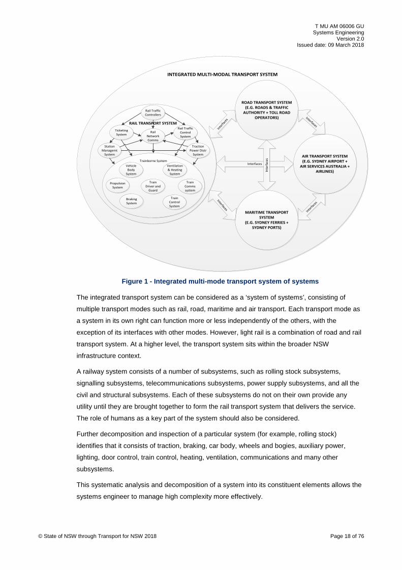
7. System overview The multi-modal transport system should be understood and described in order to assist in
planning SE activities and assigning roles to a transport project, its environment and functional
and physical boundaries.
Figure 1 shows an integrated multi-modal transport system.
© State of NSW through Transport for NSW 2018 Page 17 of 76
T MU AM 06006 GU Systems Engineering
Version 2.0 Issued date: 09 March 2018
INTEGRATED MULTI-MODAL TRANSPORT SYSTEM
RAIL TRANSPORT SYSTEM
ROAD TRANSPORT SYSTEM(E.G. ROADS & TRAFFIC
AUTHORITY + TOLL ROAD OPERATORS)
MARITIME TRANSPORT SYSTEM
(E.G. SYDNEY FERRIES + SYDNEY PORTS)
Interfac
es
Interfaces
Interfaces
TicketingSystem
Rail Traffic Control System
Traction Power Distr
System
Station Managemt
System
Trainborne SystemVehicle
Body System
Ventilation & Heating
System
Propulsion System
Train Comms system
Braking System
Train Driver and
Guard
Train Control System
Rail Traffic Controllers
Rail Network Comms
AIR TRANSPORT SYSTEM(E.G. SYDNEY AIRPORT +
AIR SERVICES AUSTRALIA + AIRLINES)
Interfaces
Interface
s
Inte
rface
s
© State of NSW through Transport for NSW 2018 Page 18 of 76
Figure 1 - Integrated multi-mode transport system of systems
The integrated transport system can be considered as a ‘system of systems’, consisting of
multiple transport modes such as rail, road, maritime and air transport. Each transport mode as
a system in its own right can function more or less independently of the others, with the
exception of its interfaces with other modes. However, light rail is a combination of road and rail
transport system. At a higher level, the transport system sits within the broader NSW
infrastructure context.
A railway system consists of a number of subsystems, such as rolling stock subsystems,
signalling subsystems, telecommunications subsystems, power supply subsystems, and all the
civil and structural subsystems. Each of these subsystems do not on their own provide any
utility until they are brought together to form the rail transport system that delivers the service.
The role of humans as a key part of the system should also be considered.
Further decomposition and inspection of a particular system (for example, rolling stock)
identifies that it consists of traction, braking, car body, wheels and bogies, auxiliary power,
lighting, door control, train control, heating, ventilation, communications and many other
subsystems.
This systematic analysis and decomposition of a system into its constituent elements allows the
systems engineer to manage high complexity more effectively.
T MU AM 06006 GU Systems Engineering
Version 2.0 Issued date: 09 March 2018
7.1. Stakeholder viewpoints Any project to introduce new or altered systems with significant levels of novelty, complexity and
risk, and therefore requiring a systems approach, has numerous stakeholders.
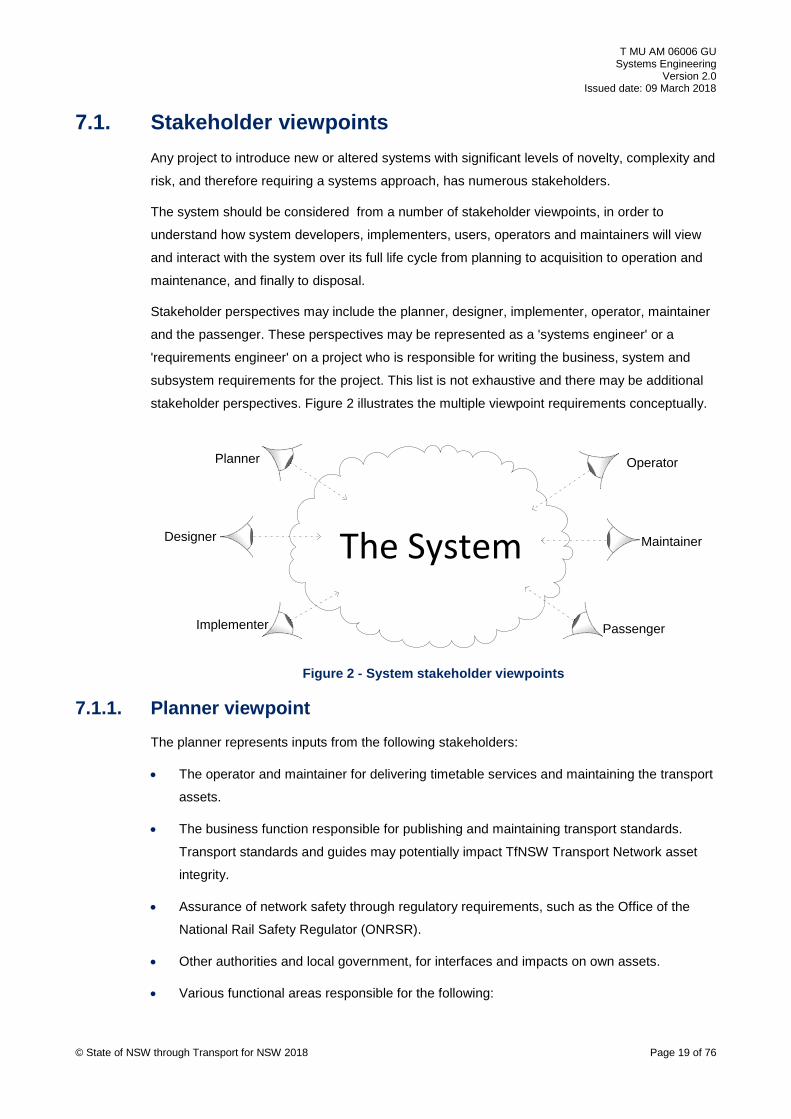
The system should be considered from a number of stakeholder viewpoints, in order to
understand how system developers, implementers, users, operators and maintainers will view
and interact with the system over its full life cycle from planning to acquisition to operation and
maintenance, and finally to disposal.
Stakeholder perspectives may include the planner, designer, implementer, operator, maintainer
and the passenger. These perspectives may be represented as a 'systems engineer' or a
'requirements engineer' on a project who is responsible for writing the business, system and
subsystem requirements for the project. This list is not exhaustive and there may be additional
stakeholder perspectives. Figure 2 illustrates the multiple viewpoint requirements conceptually.
The System
Planner
Designer
Implementer
Operator
Maintainer
Passenger
Figure 2 - System stakeholder viewpoints
7.1.1. Planner viewpoint The planner represents inputs from the following stakeholders:
• The operator and maintainer for delivering timetable services and maintaining the transport
assets.
• The business function responsible for publishing and maintaining transport standards.
Transport standards and guides may potentially impact TfNSW Transport Network asset
integrity.
• Assurance of network safety through regulatory requirements, such as the Office of the
National Rail Safety Regulator (ONRSR).
• Other authorities and local government, for interfaces and impacts on own assets.
• Various functional areas responsible for the following:
© State of NSW through Transport for NSW 2018 Page 19 of 76

T MU AM 06006 GU Systems Engineering
Version 2.0 Issued date: 09 March 2018
o Developing service level agreements with operating agencies.
o Analysing customers' needs into requirements.
o The long term transport needs of NSW and developing options based on analysis of
customer needs and freight policy. The outputs focus around the strategic business
case.
o Development of the selected option and agrees the outputs and requirements that the
business wants to achieve from investment. The outputs focus around the final
business case and agreed business requirement specification (BRS).
o Provide integrated end-to-end planning, development, delivery and operations of
transport services and projects.
The planner is involved in the ‘concept', 'specify’ and 'procure' phases of the life cycle (defined
in Section 8.2), and views the system with a focus of identifying and analysing service demand,
translating this into an operational and maintenance concept, and developing a whole-of-life
cycle business case and supporting business requirements.
The planner focuses on translating the TfNSW enterprise goals and outcomes to determine the
operational and maintenance needs, which are then used to develop the business
requirements. The planner also focuses on the system's functional, operational and
performance requirements.
7.1.2. Designer viewpoint The designer’s viewpoint is represented by the following:
• operator and maintainer in some cases (for example, for minor capital works)
• design consultancies as AEOs
• various functional areas responsible for the following:
o managing assurance up to approved for construction (AFC) before CM gate 3
o managing the design of the transport project up until construction or production, or
both
The designer views the system with an intent to translate the business requirements into system
requirements and system architecture leading to a reference design. Once the system
functional baseline and reference design is established, detailed design starts. During this
stage, the system requirements are traced and allocated to subsystems, and the functional
baseline is translated into a physical design solution, up to the AFC point.
During the process, the designer considers interfaces, RAM, EMC, human factors and safety.
This work is carried out by AEOs under contract to TfNSW project delivery organisations.
© State of NSW through Transport for NSW 2018 Page 20 of 76

T MU AM 06006 GU Systems Engineering
Version 2.0 Issued date: 09 March 2018
7.1.3. Implementer viewpoint
The implementer’s viewpoint is represented by the following:
• The business unit responsible for managing construction, integration and testing,
verification and validation, and post-AFC assurance up to system acceptance. The output
of this function is the entry into operational service.
• Construction and testing companies as AEOs.
• For rail project, the operator and maintainer as rail infrastructure manager (RIM) or rail
service operator (RSO) responsible for providing infrastructure access to AEOs.
The implementer views the system with an intent to translate the AFC design into a built asset,
carrying out ongoing verification and validation activities to progressively assure that the
realised asset meets the design intent and original client requirements. The implementer works
with the designer to plan and execute all systems integration and testing activities.
7.1.4. Operator and maintainer viewpoint The viewpoint of an operator and maintainer is represented by the transport agencies and
contracted operators and maintainers.
While this guide is developed initially to apply directly to rail transport, the operator and
maintainer stakeholder viewpoint could extend to include other transport modes such as ferries
and buses.
The operator and maintainer views the system from the perspective of ensuring that the original
business and system requirements and the evolving system solution is operable, maintainable
and sustainable over the systems operational lifetime.
7.1.5. Passenger viewpoint The passenger's viewpoint is represented by the entity responsible for conducting, collecting,
analysing and documenting the needs of the people who use the transport service to commute
to work, school, university, airport or any other desired destination. This viewpoint is captured in
the form of customer needs and categorised under a defined set of customer value propositions
such as convenience, safety, security, comfort, accessibility and timeliness to name a few.
These customer needs should then be translated into formal statements as business
requirements on projects and then validated once the system is developed. These business
requirements could also be represented in the form of use cases to capture the specific tasks
and activities that passengers undergo when using the transport service. The development of
use cases assists in eliciting system requirements to describe what the new or altered system
will do to achieve the parent business requirement.
© State of NSW through Transport for NSW 2018 Page 21 of 76

T MU AM 06006 GU Systems Engineering
Version 2.0 Issued date: 09 March 2018
The passenger viewpoint should be considered at the outset of the project to ensure a customer
centric approach and that the right system is being delivered for the public of NSW.
For more information on customer and business requirements, refer to T MU AM 06010 GU
Business Requirements Specification.
7.2. Requirements hierarchy and structure Using a multidisciplinary approach, SE determines the following outputs at the early stages of
the system life cycle:
• functional, performance, non-functional and interface requirements
• appropriate management process requirements
• production or construction requirements
• sustainable operational and maintenance support requirements
• system disposal requirements
The development of complex integrated systems (or systems of systems) requires a top-down
approach to define, allocate and trace requirements to solutions as represented in Figure 3.
This starts with identifying the enterprise need or goals and supporting the capability concept of
operations (ConOps), then defining the concept activities in an operations concept definition
(OCD) document and maintenance concept definition (MCD) document. In addition to these
source documents, there are other informing artefacts produced on a project to support the
business requirements specification (BRS) such as hazard log, assumptions, dependencies and
constraints (ADC) register, value for money (VfM) studies, and issues register to name a few.
These documents then support the development of the business case and associated business
requirements specification (BRS).
When the business case and funding request is approved by NSW Treasury and the BRS is
issued, the project delivery business unit will use the BRS as a basis to facilitate the design and
construction of the new or altered asset.
© State of NSW through Transport for NSW 2018 Page 22 of 76

T MU AM 06006 GU Systems Engineering
Version 2.0 Issued date: 09 March 2018
Source Documents & Business Requirements
Source Documents
Subsystem Requirements
Business/user requirements
System requirements
Mgmt process requirements
Detailed Process Requirements
Transport Policy
IRS..xy1
IRS..xy1
IRS..xy1
IRS..xy1
Informing Documents
Issues Register
Risk Register
ADC Register
VfM Studies
Key to Requirements
User/Client Reqts
Rail System Reqts
Subsystem Reqts
Interface Reqts
Interface Control Docs
Rail Domain Knowledge
Requirements Structure
Interface matrix
Transport Strategy
Business Case
Ops Concept
Maint’ce Concept
Standards
Rolling Stock vehicle / Bus / Ferry vessel
Trackside signals
Control centre
Maint’ce depot
Traction power Track Civils
structure
Comms systems
Buildings / stations / bus stops
Road signals
© State of NSW through Transport for NSW 2018 Page 23 of 76
Figure 3 - Requirements hierarchy and structure
The project delivery unit establishes a project team including technical advisors (drawn from
industry AEOs) to develop the concept design up to a reference design with an associated
system requirements specification (SRS). This forms the basis of a tender.
Some organisations may choose to define management process requirements, and manage the
assurance that these process requirements are successfully implemented on the project.
T MU AM 06004 ST Requirements Schema does not make provision for management process
requirements; therefore AEOs may be required to manage them as part of overall assurance.
The reason for this is to minimise prescribing 'how' the AEO supply chain should deliver the
outcomes.
When the tender is awarded, the AEO chooses to either follow the reference design or develop
its own design. This involves allocating system requirements from the SRS into subsystem
requirements specifications (SSRS) and detailed subsystem designs.
During the course of requirements definition and analysis, inputs are identified and traced back
to source documents (policies, strategies, long term plans) and informing documents.
This development of requirements should be captured and traced in a management tool. The
selection of the applicable tool is based on complexity and contractual requirements.

T MU AM 06006 GU Systems Engineering
Version 2.0 Issued date: 09 March 2018
7.3. Concept of operations The ConOps is a high level document developed at an enterprise level in the demand and need
phase of the system life cycle. The ConOps refers to how enterprise management intends to
operate the organisation with the new system in place to satisfy the organisation's goals and
objectives as documented in the future transport strategy.
The ConOps document serves as a basis for the organisation to direct the overall
characteristics of the future business and systems required to operate the business.
The ConOps document is not a requirements document and only describes how TfNSW will
operate to execute the strategy; however it provides an overarching high-level view of the
organisation. The ConOps is used to derive a set of business and customer needs to inform the
OCD and MCD.
7.4. Operations concept The OCD describes how the new or altered system is expected to operate without detailing the
technical solution, and is used to inform the BRS and associated strategic business case.
The OCD requirements are stated in T MU AM 06006 ST.
The benefit of an OCD is to mitigate against the risk of not meeting operational requirements.
The OCD should not be seen as an optional project overhead but as an integral part of the
normal project processes.
The project team should summarise the operational concept for the new or altered system and
refer to the need for a full OCD early in the project or asset life cycle, before the final business
case and BRS.
An OCD may not be necessary to be produced for every project type, and the need for one
should be scaled and tailored to the scope and complexity of the project. An OCD is produced
at a complex multi-project program-level such as a line upgrade or capacity enhancement, and
the individual projects within that program fall, under that single program-level OCD.
Where a project significantly affects the operations, an OCD should be developed even if the
project is simple. The project should consult with relevant stakeholders to determine the need
for an OCD.
The OCD should be reviewed and refined as the system definition progresses beyond the BRS
and should be finalised when the system solution has been sufficiently defined.
The OCD is used to describe the service plan to be delivered and supporting operational
organisation, process scenarios, operating modes, and operational facilities to support that plan.
The OCD is not a requirement specification; however it is written in a manner that explains how
the new or altered system is expected to be operated over its design life. This includes any
interim operating arrangements as part of a wider operational capability migration. © State of NSW through Transport for NSW 2018 Page 24 of 76
T MU AM 06006 GU Systems Engineering
Version 2.0 Issued date: 09 March 2018
The business case and its funding request are meaningless without properly considering how
the new or altered asset would be operated and how much it would cost to operate.
An understanding of the roles and facilities that are required to support the operational concept
scenarios associated with the offered service, allows initial estimates to be made for the
operational costs over the system's operational lifetime.
The OCD should be applied and scaled at the appropriate level of novelty and complexity of the
proposed new or altered system.
For example, OHW or high voltage aerial feeder projects may not require an OCD; however an
OCD may be required at a higher portfolio or program level; for example, for a network-wide
power supply upgrade program that consists of multiple feeder, substation and OHW projects.
For non-rail transport projects, upgrading or refurbishing the propulsion system on a bus or ferry
fleet may not require an OCD but a timetable update will require an OCD as it directly affects
operations.
OCD requirements are defined in detail in T MU AM 06008 ST Operations Concept Definition
and the guidance information for developing an OCD is provided in
T MU AM 06008 GU Operations Concept Definition.
A sample OCD context diagram for a railway system is shown in Appendix D.
7.5. Maintenance concept The MCD describes how the new or altered system is expected to be maintained without
detailing the technical solution, and is used to inform the BRS and associated business case.
The MCD requirements are stated in T MU AM 06006 ST.
An MCD may not be necessary to be produced for every project type, and the need for one
should be scaled and tailored to the scope and complexity of the project.
MCD is typically produced at a complex multi-project program level such as a line upgrade or
capacity enhancement, and the individual projects within that program fall, under that single
program-level MCD.
Where a project significantly affects the maintenance, an MCD should be developed even if the
project is simple. The project should consult with relevant stakeholders to determine the need
for an MCD.
The maintenance approach has a significant impact on cost, time, resources and overall asset
condition over its expected lifetime.
The blend of planned and unplanned maintenance should be estimated, based on the selected
approach. This may include adopting a condition-based maintenance approach, where
significant capital cost is expended in providing remote condition monitoring of assets. This may
© State of NSW through Transport for NSW 2018 Page 25 of 76
T MU AM 06006 GU Systems Engineering
Version 2.0 Issued date: 09 March 2018
result in better prediction of potential failures, and may lead to reduced response times, lower
mean time to repair, and higher system availability.
The strategic business case and its associated funding are supported by the MCD and they are
meaningless without properly considering how the new or altered asset would be maintained
and how much it would cost to maintain and support over its full operational life (OpEx). The
business case should be based on a discounted cash flow model, beginning with accumulated
capital costs, followed by predicted maintenance expenditure, estimated revenue (ticket box
and funding subsidy), and asset depreciation over the full design asset lifetime until disposal. In
some cases, the OCD and MCD may be combined into a single document. The operations and
maintenance concepts can be combined where practicable, as they are closely related, if the
maintainer is also the operator of the system.
For example, the policy for accessing the system for maintenance purposes should consider the
impacts on the operational service and associated service performance measures. This may be
articulated in the yearly possession plan (for implementing new or altered systems and planned
maintenance) for heavy rail or 'out of service' bus booking, which is developed in collaboration
with the transport operator to ensure that suitable special arrangements are in place to minimise
service disruption.
Another example may be a business decision to move to a service that increases passenger
service hours over a 24-hour period, effectively reducing maintenance windows, in which case
alternative system maintenance and access arrangements need to be articulated in the MCD.
The maintenance concept should be written in accordance to T MU AM 06009 ST Maintenance
Concept Definition.
7.6. Functional architecture The functional architecture requirements are stated in T MU AM 06006 ST.
The project should describe the hierarchy of functions for the new or altered system, and how it
relates back to concept activities, capabilities and enterprise goals. The project should also
describe if required, the system in terms of functional flow block diagrams (FFBD) with functions
decomposed until all functions are purely system performed functions.
While a functional architecture may be structured around physical asset groups, it is not
necessarily the case. Where practicable, the functional architecture should avoid being tightly
linked to physical systems and assets. The reason for this is that functions allocated to physical
assets using old or current technology, may in future be allocated to other physical assets that
can provide superior functionality and performance. The logical or functional description
changes slowly while the physical description changes much faster, particularly as the pace of
technological change quickens. De-linking of functions from physical asset groups permits
innovative solutions to be offered by existing and new product suppliers.
© State of NSW through Transport for NSW 2018 Page 26 of 76
T MU AM 06006 GU Systems Engineering
Version 2.0 Issued date: 09 March 2018
An example of this is a ‘movement authority’ that is currently issued via trackside colour light
signals. This changes to an ETCS-L2 ‘electronic movement authority’ issued via a radio block
centre and GSM-R radio network directly to the onboard train control system.
This does not imply that suppliers are permitted to offer an innovative solution for every project.
In many cases from a logistic support perspective it is not practical to have a large range of
novel and diverse solutions and assets to maintain. Standard solutions using type approved
products in proven standard configurations may still be more desirable than novel solutions in
many cases.
Projects using established type approved products in standard configurations, and heavy civil
engineering assets may not need to develop a functional architecture, as it mostly benefits
high-complexity, high-integrity command and control and communications systems with
significant embedded software functionality.
In order to develop a functional architecture, a standard reference architectural framework
should be adopted that ensures a common approach and syntax to defining the functions.
TRAK metamodel developed by RSSB (UK), and adopted by the ASA as a core element of its
model based systems engineering (MBSE) approach, is used as a reference guide. This forms
the basis of the Transport Network Architecture (TNA) model.
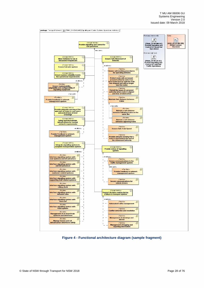
Figure 4 shows an example of a functional architecture sample fragment from the TNA model
using TRAK. The diagram ID is [TRAK_SV-05-MU-MD] which means it adopts the TRAK
solution viewpoint, multi-modal and multi-disciplined showing a set of signalling functions that
realise a set of concept activities for heavy rail and light rail vehicles.
© State of NSW through Transport for NSW 2018 Page 27 of 76
T MU AM 06006 GU Systems Engineering
Version 2.0 Issued date: 09 March 2018
© State of NSW through Transport for NSW 2018 Page 28 of 76
Figure 4 - Functional architecture diagram (sample fragment)
T MU AM 06006 GU Systems Engineering
Version 2.0 Issued date: 09 March 2018
7.7. Physical solution architecture The physical solution architecture requirements are stated in Section 7.3.2 of
T MU AM 06006 ST.
In some cases, the use of the term asset breakdown structure (ABS) is used in documents and
projects in TfNSW to mean system breakdown structure (SBS).
The ABS is referred as SBS in this guide and the standard (T MU AM 06006 ST), it supports.
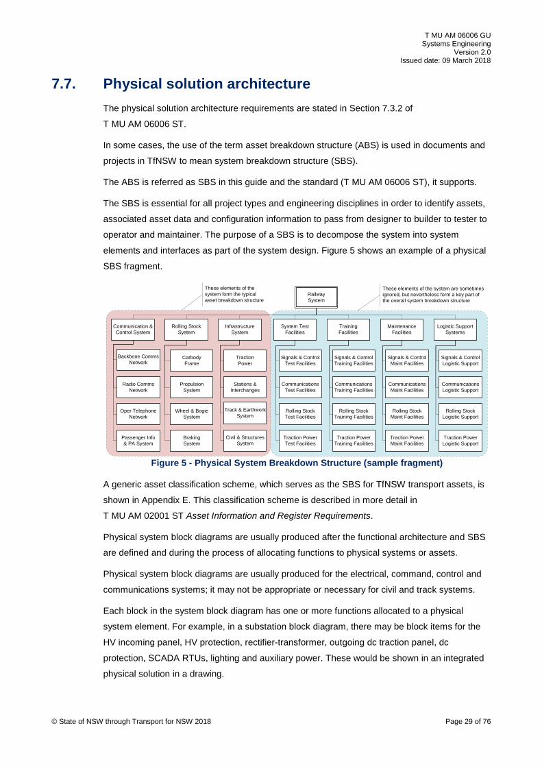
The SBS is essential for all project types and engineering disciplines in order to identify assets,
associated asset data and configuration information to pass from designer to builder to tester to
operator and maintainer. The purpose of a SBS is to decompose the system into system
elements and interfaces as part of the system design. Figure 5 shows an example of a physical
SBS fragment.
System Test Facilities
Training Facilities
Maintenance Facilities
Logistic Support Systems
Signals & ControlTest Facilities
CommunicationsTest Facilities
Rolling StockTest Facilities
Traction PowerTest Facilities
Signals & ControlTraining Facilities
CommunicationsTraining Facilities
Rolling StockTraining Facilities
Traction PowerTraining Facilities
Signals & ControlMaint Facilities
CommunicationsMaint Facilities
Rolling StockMaint Facilities
Traction PowerMaint Facilities
Signals & ControlLogistic Support
CommunicationsLogistic Support
Rolling StockLogistic Support
Traction PowerLogistic Support
Railway System
Rolling StockSystem
Infrastructure System
Communication & Control System
TractionPower
Stations &Interchanges
Track & EarthworkSystem
Civil & StructuresSystem
CarbodyFrame
PropulsionSystem
Wheel & BogieSystem
BrakingSystem
Backbone CommsNetwork
Radio CommsNetwork
Oper TelephoneNetwork
Passenger Info& PA System
These elements of the system are sometimes ignored, but nevertheless form a key part of the overall system breakdown structure
These elements of the system form the typical asset breakdown structure
© State of NSW through Transport for NSW 2018 Page 29 of 76
Figure 5 - Physical System Breakdown Structure (sample fragment)
A generic asset classification scheme, which serves as the SBS for TfNSW transport assets, is
shown in Appendix E. This classification scheme is described in more detail in
T MU AM 02001 ST Asset Information and Register Requirements.
Physical system block diagrams are usually produced after the functional architecture and SBS
are defined and during the process of allocating functions to physical systems or assets.
Physical system block diagrams are usually produced for the electrical, command, control and
communications systems; it may not be appropriate or necessary for civil and track systems.
Each block in the system block diagram has one or more functions allocated to a physical
system element. For example, in a substation block diagram, there may be block items for the
HV incoming panel, HV protection, rectifier-transformer, outgoing dc traction panel, dc
protection, SCADA RTUs, lighting and auxiliary power. These would be shown in an integrated
physical solution in a drawing.

T MU AM 06006 GU Systems Engineering
Version 2.0 Issued date: 09 March 2018
Figure 6 shows a sample fragment of a physical system block diagram for a portion of a rapid
transit railway communications based train control (CBTC) system.
Communication Equipment Room (CER)
Station Platforms
Station Equipment Room (SER) Depot Control Room
DepotSupervisor
WorkstationScreens
DepotSupervisorWorkstation
Dual Redundant 100Mbps Ethernet Depot Control LAN (local)
Depot-OCCEthernetSwitch
Fax
Dual 100Mbps Ethernet ILS-OC Vital Signalling LAN
Platform Screen Doors (PSD)
Vital I/O
VirtualBlock
Processor
Vital I/O
ObjectController
EthernetHub x 2
100Mbps Station Ethernet LAN
RTS Base Station x 2(Main/Hot Standby)
Vital I/O
ATC RadioTransceiver
Unit
SDH/MPLSNode x 2(Main/Hot Standby)
Vital CBI Comms Nodex 2 (Main/Hot
Standby)
PIDS
PA/PIDS Client
UPS X 2
Help Point
Lighting
CCTV
Retail Machine
Speakers
CCTVConcentrator
Figure 6 - Physical system block diagram (sample fragment)
Practical railway examples of physical architecture include the following:
• signalling
o computer-based interlocking block diagrams
o control centre systems diagrams
o signalling equipment room layouts
• telecommunications
o optical fibre transmission backbone block diagrams
o communications equipment room layouts, showing SDH, ATM or MPLS units
• electrical
o earth system block diagram, showing key equipment
o SCADA system block diagram showing workstations, servers and RTUs
• track
o turnout sketch
o initial 30% (concept) design for a bridge
• buildings
o building architecture drawing or CAD 3D model, without services details
7.8. Geographic deployment architecture The geographic deployment architecture diagram facilitates design by positioning the physical
assets at a geographic location, and allows construction and maintenance organisations to
identify logistic support and incident response times.
© State of NSW through Transport for NSW 2018 Page 30 of 76

T MU AM 06006 GU Systems Engineering
Version 2.0 Issued date: 09 March 2018
Figure 7 shows a sample fragment of a geographical architecture diagram for a rapid transit
railway.
CBI Control Area B (and Group Station Control Area)CBI Control Area A (and Group Station Control Area)
Depot Control Area
OCC
Depot
Station A Station B Station C Station FStation EStation D
CBIOC
CBI
OC
ATS
OC OCCBI
OC
OC OCOCOC
Operations Control Centre (OCC)
Central Control Room (CCR)
Duty & OpsController
Spare Desk
TechnicalController
ChiefController
Videowall Overview
Incident Management Room (IMR)Dual-use for Timetable Planning
Spare Desk(dual use for incident
management and Timetable Planning
Technical Room (TR)
Signalling Maintainer
Desk
Figure 7 - Geographic architecture diagram (sample fragment)
Practical railway examples of geographic architecture that indicate the geographic layout and
disposition of physical assets and systems include, but are not limited to, the following:
• geospatial (GIS) models of the transport corridor, assets and facilities
• signalling
o signalling plans: locating signalling assets along the rail corridor
o track insulation plans: locating insulation and bonding to OHWS in the corridor
o cable route plan: locating cable routes, joint pits and cable crossings
o level crossing layout plans: locating signals, traffic lights, road signs
o drivers diagrams: locating signals, points, indicators, signage, radio channels
• telecommunications
o telecommunication cable route plans
• electrical
o high voltage feeder routes
o high voltage operating diagrams
o substation layout drawings
o HV/traction switching diagrams
• track
o depot and stabling yard layout plans
o track plans
o level crossing plans
© State of NSW through Transport for NSW 2018 Page 31 of 76

T MU AM 06006 GU Systems Engineering
Version 2.0 Issued date: 09 March 2018
7.9. Interface architecture Entity-relationship diagrams can be used to define interfaces and interactions between systems.
Figure 8 shows a sample fragment of a system context diagram.
IF0601Cable Route
OB028 Comms
Equip
OB027 Stations
IF0624Power
IF0623EMI
OB034 Signalling
Power
OB036SER SIGNALLING EQUIPMENT(1)
(Level 3 Context)
Includes:Router, GPS Clock, Interface Unit, Switches, Local Computer, Interlocking, Block Processor, Monitor & Control, Maintenance Terminal, Data Logger, Radio System, Track Circuit Equip, Signalling Interface Circuits, Relays, Power Supply Units
Member of:FIXED SIGNALLING (OB033)
IF0123Damage/ Disrupt
IF0609Diagnostics
IF0175EMI
IF0610Control Access
IF0608Maintain/ Prepare
OB022 Traction Power
IF0595EMI
OB016 Railway Neighbours
(Industry, Commerce, Domestic…)
IF0098Control Access
OB037IMR/RR Equip
IF0556EMI IF1287
Status
IF0559Data
Stream
IF0602E&B
OB035SCC/ATS
Equip
IF0614Status
IF0615Control
OB036SER Equip
(Other)IF0620Data
Stream
IF0622Status
IF0613Diagnostics
OB071Current RelayIF0594
Status
IF0600Location
IF0593Power
IF0557Control
IF0621Control
IF0625Status
OB032SMS Equip
IF0612Data
Stream
IF0617E&BIF0616
EMI
IF0618E&B IF0619
E&B
OB025 Buildings
IF0603Location
IF0582Alarms
IF0583Status
IF0584Control
OB005Other Lines
IF0830E&B
OB105Portable Test
Equipment
IF1041 Data
Stream
IF1210CommsServices
OB003Train
IF0599EMI
OB098Eng Train
IF1211EMI
See also SER Equip
(2)
OB015 Earth
IF1219E&B
OB004Depot IF1257
Control
IF1259Status
IF1265Train Description
IF1266Train Crew Info.
IF1291Control
OB012Time
Reference
IF1246Synchronise
IF1349Status
IF1412Synchronise
OB079Trespasser
/Vandal
OB081Asset
Custodian
Figure 8 - System context/interface diagram (sample fragment)
These diagrams can be augmented by N-squared charts, which facilitate planning and
specification of system interfaces in detail via interface control documents (ICDs) and interface
requirements specifications (IRS), depending on level of complexity. An example of an
N-squared chart in the form of an interface control document (ICD) matrix is shown in
Appendix F.
7.10. Interim system migration states On high-complexity programs and portfolios of projects such as Sydney Metro, automatic train
protection (ATP), power supply upgrade (PSU) or fleet replacement, commissioning the entire
new or altered system into operation in one stage may not be possible.
Interim configuration states and migration from one configuration state to the next should be
identified, planned and scheduled. This may include interim pre-testing of systems in an ‘over
© State of NSW through Transport for NSW 2018 Page 32 of 76

T MU AM 06006 GU Systems Engineering
Version 2.0 Issued date: 09 March 2018
and back’ arrangement, and then leaving them dormant (that is not commissioned into full
operation) to await readiness of other related systems for system integration at a later date.
These interim configuration states should be identified and described as part of the architectural
diagram viewpoints as described in Section 7.6, Section 7.7 and Section 7.8.
8. System life cycle description T MU AM 06006 ST mandates deploying a whole-of-life systems engineering approach to the
planning and acquisition of the new or altered system.
Most systems engineers and project managers are familiar with the traditional V model of the
system life cycle defined in the INCOSE SE Handbook. This model maps a vertical scale of
increasing system definition (system, subsystem, and unit) against a horizontal timescale of
system life cycle phases from exploratory phase (need identification and pre-feasibility) through
to retirement phase (disposal). Figure 9 shows the TfNSW system life cycle V model.
© State of NSW through Transport for NSW 2018 Page 33 of 76
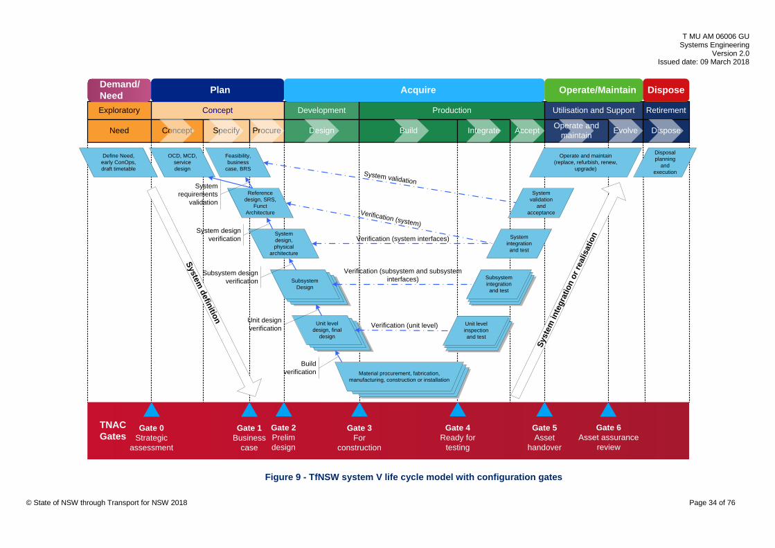
T MU AM 06006 GU Systems Engineering
Version 2.0 Issued date: 09 March 2018
TNAC Gates
Gate 1Business
case
Gate 3 For
construction
Gate 0Strategic
assessment
AcceptNeed Concept Specify Procure Design Build Integrate Operate and maintain Dispose
Concept Development Production Utilisation and Support Retirement
Verification (system)
Verification (system interfaces)
Material procurement, fabrication, manufacturing, construction or installation
Unit level inspection and test
Unit level design, final
design
OCD, MCD, service design
Define Need, early ConOps, draft timetable
Subsystem integration and test
System integration and test
Disposal planning
and executionSystem validation
Verification (subsystem and subsystem interfaces)
Verification (unit level)
System validation
and acceptance
Subsystem Design
System design, physical
architecture
Reference design, SRS,
Funct Architecture
Operate and maintain (replace, refurbish, renew,
upgrade)
Plan Acquire Operate/Maintain
Gate 2 Prelim design
System definition
Gate 4 Ready for
testing
Gate 6 Asset assurance
review
Syst
em in
tegr
atio
n or
real
isat
ion
Gate 5 Asset
handover
Dispose
Feasibility, business
case, BRS
Exploratory
Evolve
System requirements
validation
System design verification
Subsystem design verification
Unit design verification
Build verification
Demand/Need
© State of NSW through Transport for NSW 2018 Page 34 of 76
Figure 9 - TfNSW system V life cycle model with configuration gates
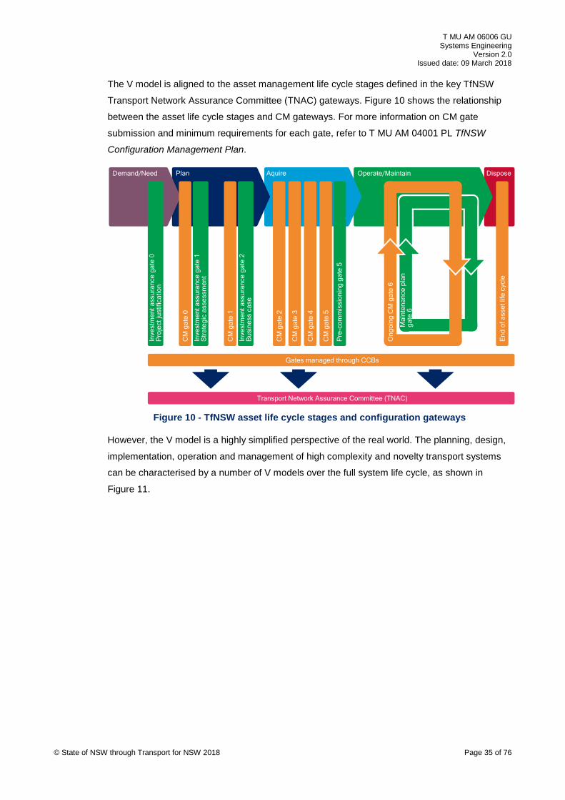
T MU AM 06006 GU Systems Engineering
Version 2.0 Issued date: 09 March 2018
The V model is aligned to the asset management life cycle stages defined in the key TfNSW
Transport Network Assurance Committee (TNAC) gateways. Figure 10 shows the relationship
between the asset life cycle stages and CM gateways. For more information on CM gate
submission and minimum requirements for each gate, refer to T MU AM 04001 PL TfNSW
Configuration Management Plan.
CM
gat
e 0
CM
gat
e 1
CM
gat
e 2
CM
gat
e 3
CM
gat
e 4
CM
gat
e 5
End
of a
sset
life
cyc
le
Inve
stm
ent a
ssur
ance
gat
e 2
Bus
ines
s ca
se
Inve
stm
ent a
ssur
ance
gat
e 1
Str
ateg
ic a
sses
smen
t
Pre
-com
mis
sion
ing
gate
5
Inve
stm
ent a
ssur
ance
gat
e 0
Pro
ject
just
ifica
tion
Gates managed through CCBs
Transport Network Assurance Committee (TNAC)M
aint
enan
ce p
lan
gate
6
Ong
oing
CM
gat
e 6
Demand/Need Plan Aquire DisposeOperate/Maintain
© State of NSW through Transport for NSW 2018 Page 35 of 76
Figure 10 - TfNSW asset life cycle stages and configuration gateways
However, the V model is a highly simplified perspective of the real world. The planning, design,
implementation, operation and management of high complexity and novelty transport systems
can be characterised by a number of V models over the full system life cycle, as shown in
Figure 11.

T MU AM 06006 GU Systems Engineering
Version 2.0 Issued date: 09 March 2018
PR
OD
UC
T LEV
EL
AP
PLIC
ATIO
N LE
VE
L
SPECIFIC SYSTEM APPLICATION PROJECT
(TfNSW Project Delivery + D&C AEO)
GENERIC PRODUCT ADAPTATION (SUPPLIER AEO)
SYSTEM SUPPORT (OpCo AEO)
PRODUCT SUPPORT
(SUPPLIER AEO)
GENERIC SYSTEM APPLICATION
(TfNSW Project Delivery + AEO)
GENERIC PRODUCT DEVELOPMENT
(SUPPLIER AEO)
Figure 11 - Composite SE life cycle models
8.1. Integrated system life cycle The multiple-system life cycle is viewed from the specific application and generic product
perspective and is elaborated more in detail in Figure 19 of Appendix C.
This expansion of the V model may take many forms and depends on the nature of the project.
The generic system application life cycle applies to pilot or trial projects run by TfNSW to
develop a proof of concept and standard generic approach to application of new technology at a
system level (for example, Opal ticketing system on all public transport services and eventually
trialling contactless EFTPOS card services).
The specific system application life cycle applies to specific system implementation projects
planned by the planners, and delivered under contracts by the project delivery group.
The system support life cycle applies to mid-life upgrades by the operator and maintainer to
address mid-life performance, reliability or safety issues. These are considered as 'mini projects'
such as track renewal or refurbishment, sectioning hut relocation or track slewing to enhance
line speed, but do not involve new or altered assets.
The generic product development (supplier) life cycle applies to original products developed by
suppliers, from product inception to release and generic acceptance. An example could be a
computer-based interlocking (CBI) product developed by an original equipment manufacturing
(OEM) supplier for use by multiple client organisations on their transport network (possibly with
client-specified adaptations).
The generic product adaptation (supplier) life cycle applies to generic products developed by
the OEM suppliers that require some adaptation to meet specific client organisation application
© State of NSW through Transport for NSW 2018 Page 36 of 76

T MU AM 06006 GU Systems Engineering
Version 2.0 Issued date: 09 March 2018
requirements. An example could be the adaptation of interlocking data constructs and software
rules in a computer-based interlocking to suit signalling principles of a local railway operator.
The OEM supplier is responsible for managing generic product adaptation with TfNSW input.
The generic product support (supplier) life cycle applies to original products developed by OEM
suppliers, adapted for specific applications, and installed on the client network, that require
ongoing OEM logistic support in terms of mid-life software upgrades or hardware modifications.
Further complexity is introduced into the practical application of the V life cycle model when
planning and acquiring complex transport systems. However, not all subsystem development
starts at the same time, as shown in Figure 19 of Appendix C.
8.2. System life cycle phases The INCOSE Systems Engineering Handbook defines a number of life cycle stages that a
system passes through, which broadly align with the TfNSW asset life cycle. These stages are
interpreted in Section 8.2.1 through to Section 8.2.7.
8.2.1. Exploratory phase The exploratory phase maps to the demand and need stage in the TfNSW asset life cycle. The
exploratory phase may be referred to as the 'need' phase.
The key responsible parties include the following functional areas:
• entity responsible for analysing customers' needs into requirements
• strategic transport planning
• entity responsible for developing service level agreements with operating agencies
The operator and maintainer or RIM may also be involved in this stage and all other life cycle
stages as part of due diligence accountability under Rail Safety National Law or Work Health
and Safety Act.
The key activities and deliverables include transport needs analysis, development of multiple
service options, high level business needs and an early ConOps.
8.2.2. Concept phase The concept phase maps to the 'plan' stage (concept, specify and procure) in the TfNSW asset
life cycle.
The key responsible parties include the following functional areas:
• strategic transport planners
• project delivery group
© State of NSW through Transport for NSW 2018 Page 37 of 76
T MU AM 06006 GU Systems Engineering
Version 2.0 Issued date: 09 March 2018
• AEOs contracted to provide technical advice and operator and maintainer providing
services as an AEO under contract to TfNSW
The key activities and deliverables include high-level transport performance modelling to
validate the following:
• early OCD and MCD development
• preferred option concept design
• timetable
• benefits realisation management plan
• business case
• tender documentation
• systems engineering management plan (SEMP)
• early operational readiness and change management planning
• verification and validation (V&V) plan
• P50/P90 risk-assessed cost estimates
• early consideration of human factors integration (HFI)
• BRS
• draft SRS
• approved business case
• setting of RAM and other key system performance targets
8.2.3. Development phase The development phase maps to the 'acquire' stage (design) in the TfNSW asset life cycle.
The key responsible parties include, project delivery group within TfNSW and AEOs contracted
to provide design services to TfNSW in this stage.
The key activities and deliverables include OCD and MCD refinement, final SRS, development
of detailed designs, product specifications, process specifications, material specifications, V&V
strategies, consideration of HFI and RAM performance considered, and finalised operational
readiness and change management plans.
8.2.4. Production phase The production phase maps to the ‘acquire stage’ (build, integrate, and accept) in the TfNSW
asset life cycle.
© State of NSW through Transport for NSW 2018 Page 38 of 76

T MU AM 06006 GU Systems Engineering
Version 2.0 Issued date: 09 March 2018
The key responsible parties include, project delivery group within TfNSW, AEOs contracted to
provide the services of supply, manufacturing or fabrication, site installation, integration, testing
and commissioning to TfNSW, and may involve the operator and maintainer.
The key activities and deliverables include development of detailed designs, bills of materials,
product specifications, procuring or fabricating products or equipment, installation or
construction and integration on site, subsystem and system testing, commissioning, operational
readiness demonstration and handover to the TfNSW asset owner and operator and maintainer.
8.2.5. Utilisation phase The utilisation phase maps to the 'operate and maintain' stage of the TfNSW asset life cycle.
The key responsible parties include the transport agencies, contracted operator and maintainer
and other transport operators.
The key activities and deliverables include asset acceptance from the project delivery
organisation, operational safety argument, ongoing operation of these assets, and periodic
major maintenance or minor capital projects to restore system performance capability to the
original design intent.
8.2.6. Support phase
The support stage maps to ‘operate and maintain’ stage of the TfNSW asset life cycle, and runs
concurrently with the utilisation stage.
The key responsible parties include the transport agencies or contracted asset management
AEOs and AEO product suppliers.
The key activities and deliverables include asset acceptance from the project delivery
organisation, asset condition assessments, preparing asset maintenance plans, performing
failure reporting, analysis and corrective action system (FRACAS), carrying out general asset
maintenance and logistic support activities (including mid-life upgrades) against these plans.
8.2.7. Retirement phase
The retirement phase maps to the 'dispose' stage of the TfNSW asset life cycle.
The key stakeholders include the transport agencies and other contracted asset management
and operations organisations who may be AEOs, making the decision as to when an asset
should be retired from operational service.
The key activities and deliverables include asset condition assessments to support any
decisions to retire systems that have reached the end of their design life, or changes in asset
utilisation.
© State of NSW through Transport for NSW 2018 Page 39 of 76
T MU AM 06006 GU Systems Engineering
Version 2.0 Issued date: 09 March 2018
The reasons why the asset or system may be retired are as follows:
• The system was designed with the intent to dispose after its expected life and is no longer
useable or supportable, or both. This option suggests that the system was designed with
the intent to 'dispose' it.
• Subsystems or assemblies of the system were designed with the intent to last less than the
expected life of the whole system and therefore need to be retired to make way for a new
or altered subsystem. This option suggests that the system was designed with the intent to
'refurbish' or 'remanufacture' the system.
• The system still meets the operational requirements but the business need for the system
may have changed resulting in retirement of assemblies or components to satisfy the new
business needs or retiring the system as a whole.
• System may be damaged and is beyond repairable.
Once the reasons for potential retirement have been identified, each can be examined for
potential retirement methods such as:
• Sell the asset as a second-hand item.
• Re-used as a training aid.
• Destroyed and disposed as waste.
• Disassembled and working subsystems used on the new system. This also includes items
that need to be scrapped, recycled or both.
• Re-purposed (for example, heritage building becoming museums).
Once the retirement methods have been identified, the operator and maintainer of the retired
asset may identify any design issues that may arise for the new or altered system such as:
• avoidance of the use of hazardous or toxic materials
• observe recycling regulations
• environmental impact
• cost of; disposal, destruction, uninstallation or refurbishment
• transportation cost for disposal
• need for specialised personnel and equipment required for disposal
• availability of design data and drawings to support disposal at the end of life of asset
© State of NSW through Transport for NSW 2018 Page 40 of 76

T MU AM 06006 GU Systems Engineering
Version 2.0 Issued date: 09 March 2018
9. Systems engineering organisation structure A matrix organisational structure divides authority both by functional area and delivery work
stream. In a matrix structure, each team member reports to two immediate managers, that is, a
functional lead (technical SME) and a delivery lead (manager); Figure 12 shows sample
fragment of typical matrix-based railway project delivery organisation.
Change Sponsor
Program/Proj Director
EngineeringManager
OtherProject Mgmt
Stage 2 ProjManager
Stage N ProjManager
Stage 1 ProjManager
SEManager
ArchitectureManager
RequirementsManager
V&VManager
Tech InterfaceManager
RAMSManager
HF IntegrationManager
ConfigurationManager
EMCManager
Sys/Operational IntegrationManager
Functional Discipline Civil/StructuresDiscipline Lead
GeotechnicalDiscipline Lead
TrackworksDiscipline Lead
SignallingDiscipline Lead
Elec TractionDiscipline Lead
Control SystemsDiscipline Lead
Overhead WiringDiscipline Lead
TelecommsDiscipline Lead
Drain/HydrologyDiscipline Lead
Del
iver
y S
tream
ConstructionManager
DesignManager
Test/CommManager
Figure 12 - Matrix project organisation (sample fragment)
The functional leads are charged with overseeing staff in a functional specialist area such as an
engineering discipline (civil, track, signalling) or SE role (requirements, RAMS, V&V).
The delivery leads manage specific and time-constrained work packages within each project.
They draw engineering staff from various technical SME functional areas to deliver their specific
work packages within the project.
The following are some of the advantages of matrix organisational structure:
• resource coordination (leads focus on area of expertise, either engineering or PM)
© State of NSW through Transport for NSW 2018 Page 41 of 76
T MU AM 06006 GU Systems Engineering
Version 2.0 Issued date: 09 March 2018
• specialisation (staff focus on applying their specific domain knowledge to the project)
• breadth of skill
• communication (not more than two layers of communication to the executive)
• flexibility of the team to redeploy resources
The sample structure in Figure 12 is for a large project or program, where each function or
activity requires a uniquely defined management role. For smaller projects, staff may have
multiple roles and the layers of project management would be reduced. Scaling and tailoring of
SE effort is essential.
9.1. Systems engineering roles and responsibilities In any organisation, the entity responsible for the delivery of SE services to support the
acquisition and implementation of new or altered systems should ensure that all SE roles and
associated responsibilities are clearly defined.
In many cases a single role may be assigned with more than one SE responsibility where
scaling and tailoring of SE effort is appropriate on simpler projects.
SE organisation roles and responsibilities should not duplicate or conflict with other
management areas of the overall organisation; for example, project management, procurement,
risk, system safety assurance and others.
For simple projects the SE effort may be carried out by the design team or principal contractor.
An SE organisation with dedicated role descriptions is not always necessary (for example, SE
manager, requirements manager, interface manager, and so on.), as long as the appropriate
level of SE is carried out competently by the organisation.
For example in some simpler projects, elements of SE effort could be carried out by the design
manager or engineering manager. For very simple projects, the project manager, engineering
manager and design manager roles may be combined and some basic SE effort may be carried
out by the consolidated role.
Table 1 identifies key SE management roles in an organisation that deals with high levels of
novelty, complexity and risk in the planning and acquisition of new or altered systems. It assigns
key responsibilities to each role on the basis of a complex project.
This does not imply that all the SE roles and responsibilities are required for every project. For
simple projects using type approved products in standard configurations; for example, OHW or
track renewal or upgrade projects, an SE manager is not practical.
Similarly, for extremely complex and novel systems such as ETCS-L2, SE responsibilities listed
in Table 1, represents the minimum SE roles and responsibilities.
© State of NSW through Transport for NSW 2018 Page 42 of 76

T MU AM 06006 GU Systems Engineering
Version 2.0 Issued date: 09 March 2018
Table 1 – Systems engineering roles and responsibilities
Role Responsibilities
Systems engineering manager
• identify SE management requirements, effort and work breakdown structure (WBS)
• identify SE resources required to support SE activities appropriate to the project phase
• assign clear responsibilities and accountabilities to SE team members • support project manager (PM) to implement effective controls and measures in
delivery of engineering outputs throughout the project life cycle by tailoring the SE principles
• support design and engineering functions to control and assess the health and maturity of the engineering outputs throughout the project life cycle
• ensure technical reviews to enable progressive assurance are included in scope of works between TfNSW and third parties delivering services and products
• ensure systems interface management and coordination activities between project work streams are implemented, and results documented and distributed
• review contractor submissions for compliance with SE requirements • identify and report on compliance gaps against SE practices adopted on the
project
Requirements manager
• identify stakeholders and the level of requirements management needed on the project
• develop a requirements management (RqM) plan to support the requirements engineering, including activities in support of safety and human factors integration
• identify, select, implement and maintain an appropriate RqM tool • plan, organise and facilitate requirements definition workshops with relevant
and authorised project stakeholders to obtain input to the requirements definition
• elicit requirements, configure, compile and update the requirements database (RqDB) to support establishing requirements baselines in alignment with major project phases
• compile requirements specifications with SE team members and stakeholders • produce baseline requirements specifications (BRS, SRS, SSRS, IRS) • monitor and report on requirements allocation and traceability • communicate and coordinate activities with other SE management activities
Systems integration manager
• identify systems integration (including migration and interim configuration) requirements
• establish and maintain a systems integration plan (SIP) as required • identify, implement and use systems integration (SI) tools as required • execute SI tasks and activities related to the engineering effort • communicate and coordinate SI activities with other SE management activities
Operational integration manager
• establish and maintain OCD and MCD documents • prepare the operational readiness plan • coordinate and direct the training, competency and learning plan • develop, and direct implementation of the change management plan • lead and direct stakeholder management activities
© State of NSW through Transport for NSW 2018 Page 43 of 76
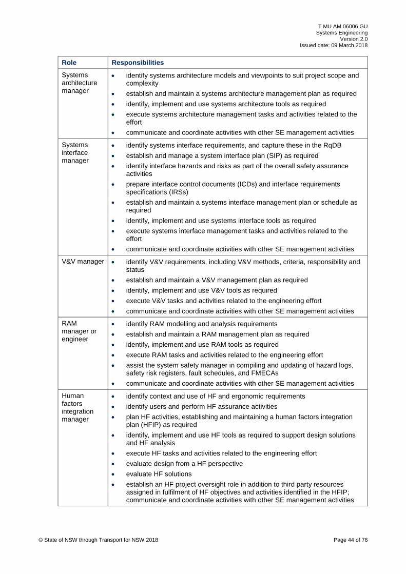
T MU AM 06006 GU Systems Engineering
Version 2.0 Issued date: 09 March 2018
Role Responsibilities
Systems architecture manager
• identify systems architecture models and viewpoints to suit project scope and complexity
• establish and maintain a systems architecture management plan as required • identify, implement and use systems architecture tools as required • execute systems architecture management tasks and activities related to the
effort • communicate and coordinate activities with other SE management activities
Systems interface manager
• identify systems interface requirements, and capture these in the RqDB • establish and manage a system interface plan (SIP) as required • identify interface hazards and risks as part of the overall safety assurance
activities • prepare interface control documents (ICDs) and interface requirements
specifications (IRSs) • establish and maintain a systems interface management plan or schedule as
required • identify, implement and use systems interface tools as required • execute systems interface management tasks and activities related to the
effort • communicate and coordinate activities with other SE management activities
V&V manager • identify V&V requirements, including V&V methods, criteria, responsibility and status
• establish and maintain a V&V management plan as required • identify, implement and use V&V tools as required • execute V&V tasks and activities related to the engineering effort • communicate and coordinate activities with other SE management activities
RAM manager or engineer
• identify RAM modelling and analysis requirements • establish and maintain a RAM management plan as required • identify, implement and use RAM tools as required • execute RAM tasks and activities related to the engineering effort • assist the system safety manager in compiling and updating of hazard logs,
safety risk registers, fault schedules, and FMECAs • communicate and coordinate activities with other SE management activities
Human factors integration manager
• identify context and use of HF and ergonomic requirements • identify users and perform HF assurance activities • plan HF activities, establishing and maintaining a human factors integration
plan (HFIP) as required • identify, implement and use HF tools as required to support design solutions
and HF analysis • execute HF tasks and activities related to the engineering effort • evaluate design from a HF perspective • evaluate HF solutions • establish an HF project oversight role in addition to third party resources
assigned in fulfilment of HF objectives and activities identified in the HFIP; communicate and coordinate activities with other SE management activities
© State of NSW through Transport for NSW 2018 Page 44 of 76

T MU AM 06006 GU Systems Engineering
Version 2.0 Issued date: 09 March 2018
Role Responsibilities
EMC manager or engineer
• identify potential EMC threats and EMC modelling and analysis requirements • establish and maintain an EMC management plan as required • identify, implement and use EMC modelling and testing tools as required • execute EMC management tasks and activities related to the engineering
effort • assist the system safety manager in compiling and updating of hazard logs,
safety risk registers with EMC-related hazards • communicate and coordinate EMC activities with other SE management
activities
Configuration manager
• identify configuration management requirements, including configuration item lists
• establish and maintain a configuration management plan as required • identify, implement and use configuration management tools as required • execute configuration management tasks and activities related to the
engineering effort • communicate and coordinate configuration management activities with other
SE activities
9.2. Project organisation Project organisations are scaled and structured according to the scope, scale and complexity of
the system (or system or systems) to be delivered. The effort of systems engineering should be
scaled and tailored to suit the following organisations:
• Portfolio management organisations are structured to provide a wide portfolio of programs,
which in turn each may consist of multiple projects. Examples of this include portfolio
alliance organisations such as Future Transport Strategy group.
• Program integration management organisations include the ATP, PSU, 2018 TT, and
DTRS programs, which each consist of multiple projects to deliver specific subsystems or
geographic scopes.
• Product development organisations include OEM that provides generic products that are
approved, selected and procured for specific application.
• Project development organisations include TfNSW project delivery group, and (to some
extent) relevant operator and maintainer agencies such as Sydney Trains, Roads and
Maritime Services (RMS), NSW Light Rail, NSW Trains and State Transit Authority (STA)
who develop projects to the point where an SRS and a costed reference design are issued
to tender.
• Project delivery organisations such as TfNSW project delivery group and supply chain
AEOs who deliver the scope of works in terms of detailed designs, procurement,
manufacturing or fabricating, installation, integration, testing, commissioning, acceptance
and hand over to the asset operator.
© State of NSW through Transport for NSW 2018 Page 45 of 76

T MU AM 06006 GU Systems Engineering
Version 2.0 Issued date: 09 March 2018
• Operator and maintainer organisations include the transport agencies and contracted
operators and maintainers. They plan, execute and measure asset maintenance of TfNSW
assets, and these may take the form of a renewal or replacement or refurbishment project.
9.3. RACI Matrix The levels of responsibility and engagement of key organisational roles should be mapped to
SE and related processes in a RACI (responsible, accountable, consulted, informed) matrix,
and communicated to all staff. While the RACI is not the only way to easily identify and
communicate responsibility, it is the most commonly used and understood method.
The partially completed example of a RACI matrix in Figure 13 broadly represents a project
engineering organisation and the associated responsibilities for a high complexity and high
novelty program of works.
KEY:R = ResponsibleA = AccountableC = ConsultedI = Informed
Change Sponsor
Acceptance Client
Program/Project Delivery
OpCo (Operators & Maintainers)
External (Council, Utilities)
Project Director
Project Manager(s)
System Safety Manager
Document/Data M
anager
Operational Integration Manager
Engineering Manager
Systems Engineering Manager
Requirements Manager
Human Factors Integration Manager
Technical Interface Manager
RAM Manager
V&V Manager
Design Manager
Construction Manager
Test & Comm
issioning Manager
Design Consultants
Product Suppliers/Manufacturers
Construction Contractors
Stakeholders Project Leadership SE & Related Management Contractor
Operation & Maintenance Analysis I I C A C C C R C C RRequirements Management I I C A C C R R C C C C CSystem Modelling & Analysis A C R C I C C C CSystem Architecture Management A C R C C C CSoftware/Data Development A C R C C C C CDesign Management A C R C C C C C R C RManufacturing Management A C R C C RConstruction Management A C R C R RSystems Integration Management I I A C C C C C RInspection & Test Management A C C R C C C C C R RVerification & Validation Management A C C R C C C C R CCompliance Management A C C I R C R CPerformance Demonstration A C I R C C C C RCommissioning Management I I C A C C C R C C RAcceptance Management I I R A C C C R C C C C RSystems Engineering Management A C R ICompetence Management C A C C R R C CTraining & Development Management C A C R R CSystems Assurance/Audit I I A C C R C C RConfiguration Management I I I A C C R C C CEngineering Change Management I I A C C R C CDocument & Data Management I I I I A C C R C C C C C C C C C C C C C CTechnical Interface Management A C C R C C RTechnical Issues Management A C C R C CRAM Management I I A C C R C C RSystem Safety Management I I I A R C C R C C C CHuman Factors Integration C A C C C R C R C C R REMC Management A C C R C C CLifecycle Support Analysis I I C A C C R C R
SYST
EMS
ENG
INEE
RING
& R
ELAT
ED M
ANAG
EMEN
T PR
OCE
SSES
PROJECT ROLESStakeholders Project Leadership SE & Related Management Contractor
© State of NSW through Transport for NSW 2018 Page 46 of 76
Figure 13 - Systems engineering RACI matrix for a high complexity project or program
T MU AM 06006 GU Systems Engineering
Version 2.0 Issued date: 09 March 2018
10. Systems engineering shared information The requirement for SE related shared information is stated in T MU AM 06006 ST.
Over the system life cycle, during planning stage and acquisition stage, a significant body of
information is generated by different technical and related processes and activities. Much of this
information is shared by multiple processes in arriving at an integrated solution that meets the
user requirements.
A good practice is to assign ownership of information to one process owner, and then to identify
the other processes that uses the shared information.
Records of due process followed by all members of the organisation who are responsible for
delivering the new or altered system are essential to provide assurance that all claims for
performance and safety of the system are traceable and supported by objective and verifiable
evidence.
A key element of the overall safety assurance claim is based on the delivery of the new or
altered system by competent persons.
The level of competence required to assure the system depends on the nature of the change. A
simple at-grade car park project outside the rail corridor clearly has a lower requirement for the
level of detailed information and records required for the assurance argument, than a project to
introduce a novel train control system. This requires tailoring and scaling to provide a pragmatic
approach to the level of complexity, novelty and risk.
Figure 14 illustrates this ownership and usage of shared technical information.
© State of NSW through Transport for NSW 2018 Page 47 of 76

T MU AM 06006 GU Systems Engineering
Version 2.0 Issued date: 09 March 2018
KEY:O = "owns" infoU = "uses" info
Operation & Maintenance Analysis
Requirements Management
System Modelling & Analysis
System Architecture Managem
ent
Software/Data Managem
ent
Design Managem
ent
Manufacturing M
anagement
Installation Managem
ent
Systems Integration Managem
ent
Inspection & Test Managem
ent
Verification & Validation Managem
ent
Commissioning Management
Systems Engineering Management
Competence Management
Systems Assurance Management
Configuration Managem
ent
Engineering Change Managem
ent
Document & Data M
anagement
Technical Interface Management
Technical Issues Management
RAM Management
System Safety Management
Human Factors Integration
EMC Management
Lifecycle Support Analysis
SYSTEMS ENGINEERING & RELATED PROCESSESSHARED INFORMATION
Requirements Source Baseline U O U U U U U U U U U U U U U U U U U U U U U U U
Standards Baseline U U U U U U U U U U U U O U U U U U U U U U U U U
Requirements Database O U U U U U U U U U U U U U
Functional Architecture O U U U U U U U
Physical Architecture O U U U U U U U U U
Bill of Materials (BOM) O U U
Engineering Change Register U U U U U U U U U O U U U U
Configuration Database U U U U U U O U U U U U
Design Models/Information Register U U O O U O U U U U U U U U U U
Document/Data Register U U O
EMC Threat Matrix/Risk Register U U U U O
Engineering Comments Register U U O O U U U U U U U
Verification Error Log U U O U U U U
Hazard Log/Safety Risk Register U U U U U O U U
Human Factors Issues Log/Register U U U U U U U U U U U U O U
Systems Integration Schedule O U U
Technical Interface Register U U U U U U U U O U U U U
Interface Control Docs U U U U U U U U U U U O U U U U
Technical Issues Register U U U U U U U U U U U O U U U U
Technical Maintenance Plans O U U
Manufacturing Database O U U U U U U
Non-Compliance Register (audit) U U U U U U U U U U U U U U O U U U U U U U U U
Roles/Responsibilities Chart O U U U
System RAM Models (RBD) U U U U U U U U U U U U O U U U U
System Safety Models (FTA,GSN) U U U U U U U U U U U U U O U U
Product RAM Data U U U U U U O U
Product/Asset Breakdown U U U O U U U U U U U U U U U
Technical Risk Register U U U O U U U U
Project Deliverables Schedule U U U U U O U U U
Inspection & Test Logs U U U O U U U U U U U U
Operational Integration Plans U U O U U U U U U U U
Verification & Validation Evidence U U U U O U U U U U U U
Competency & Training Register U O U U
SYSTEMS ENGINEERING & RELATED PROCESSES
Figure 14 - Shared information resources and SE related processes
11. Systems engineering management plan T MU AM 06006 ST mandates that a systems engineering management plan (SEMP) be
produced when an assurance argument based on a judgement of significance (JOS) identifies
the need for a SEMP.
The need for a standalone SEMP depends on the level of scope, novelty, complexity and risk
associated with the acquisition of new or altered assets.
© State of NSW through Transport for NSW 2018 Page 48 of 76

T MU AM 06006 GU Systems Engineering
Version 2.0 Issued date: 09 March 2018
11.1. Need for a SEMP A SEMP should not be developed for each type of project, and should only be produced where
the level of SE is expected to be considerable, and requiring dedicated resources.
In the case of a large collection of similar, relatively simple projects, executed under a common
program of works (for example, station easy access projects under the Transport Access
Program), then a single program-level SEMP may be sufficient to address all SE activities
across the program.
For simple projects using type approved products in standard configurations, the need for heavy
application of SE and detailed standalone SEMP may not be justifiable. In such cases, SE may
be applied lightly and describe the SE activities within the project engineering management
plan, project delivery plan, or equivalent management plan.
For example, a project whose scope involves the delivery of an at-grade car park, overhead
wiring or a high voltage aerial feeder to a substation may not require significant SE effort, other
than the briefest of requirements, some interface management, qualitative RAM analysis, and
some qualitative EMC analysis based on compliance to established standards. This could be
embedded in a standard project delivery plan or engineering plan, and would not require a
dedicated SEMP.
11.2. SEMP and concept phase Due to the nature of SE as a whole-of-life approach to the delivery of systems, the planning of
SE activities and deliverables should begin as early as possible, particularly in the concept
phase. This allows for early definition and analysis of business requirements and how they
translate into system requirements.
The SEMP should address the system level objectives to be achieved, such as increase line
capacity from 20 trains per hour to 24 trains per hour, increase traction current in feeder
sections from 5000 Amps to 6000 Amps, or increase passenger capacity in station concourse
from 1000 to 2000.
11.3. Systems engineering deliverables CM gate 0 to gate 6 defined by the TNAC and subordinate CCB gateway requirements at the
project delivery level define the required deliverables. For example, CM gate 1 deliverables may
include (but are not limited to) the following:
• BRS and SRS complete and signed by sponsor (can be in the form of a RATM/RVTM)
• RAMS consideration appropriately addressed
• human factors considerations as appropriate
© State of NSW through Transport for NSW 2018 Page 49 of 76

T MU AM 06006 GU Systems Engineering
Version 2.0 Issued date: 09 March 2018
• systems architecture
• operational concept complete and signed by sponsor
• maintenance concept complete and signed by sponsor
• initial safety change plan established and signed by sponsor
11.4. SEMP content T MU AM 06006 ST contains a list of sections to be included in the SEMP as a minimum.
The objective or need for a change in transport functional or performance capability forms the
basis for the business requirements and system requirements, which in turn form the basis for
procuring or building the system. Without clear articulation of the top-level objective or need, a
solution that is proposed and developed may not support the need, and may lead to excessive
and unplanned whole-of-life costs.
The SEMP as one of a suite of related documents needs to be placed within the context of and
related to the other plans that form part of the management arrangements for the new or altered
system. SE as an engineering methodology cannot be carried out in isolation of project
management, safety assurance, risk management and procurement management.
The requirements structure should clearly articulate how top-level business objectives and
needs are translated into operational and service level requirements, and finally into system
level requirements that define the solution to be acquired. The requirements structure should
indicate traceability of requirements, and how they are verified and validated. Allocation of
system requirements to subsystems should be identified and controlled.
Relationships to documents such as transport plans, regulations and standards should be
shown.
The scope and boundary of the system is essential to ensure that the level of SE is scaled and
tailored accordingly to ensure value for money and an appropriate level of assurance.
The transport system is highly complex, with many physical, functional and operational
interfaces to consider, especially where the system is to be delivered as a series of interim
migration stages. The interfaces between elements inside the system boundary, as well as
interfaces to its operational environment and other systems should be clearly defined.
The SEMP should clearly define its range of control over the total system life cycle, and the
planned stage gates to be passed in order to provide progressive assurance that the system will
be accepted. The scope and extent of a SEMP can vary from one project to another.
A design and construction project may have a SEMP that extends from receipt of a reference
design and SRS through to the defect and liability phase following hand over.
© State of NSW through Transport for NSW 2018 Page 50 of 76

T MU AM 06006 GU Systems Engineering
Version 2.0 Issued date: 09 March 2018
On the other hand, a build operate transfer (BOT) joint venture organisation may require a
SEMP that extends from receipt of a BRS through to hand over of the system to TfNSW after
operating and maintaining it for 25 years.
The SEMP should describe the SE technical processes to be followed, including limits of
control, responsibilities, deliverables, tools and controlling standards and procedures. The SE
technical processes include, but are not limited to, requirements, interface, RAM, safety, EMC
and V&V management.
The SE organisation can vary significantly depending on the nature of the project change. An
at-grade car park project may have minimal and rudimentary SE activities that may be carried
out by the project manager. A medium complexity project may embed SE activities within the
engineering organisation, with SE responsibility allocated to a lead engineer and design leads.
A high complexity project with significant novelty and risk may require a specialist SE team to
carry out the full range of technical and related specialised processes.
The SEMP should describe the various share information resources to be produced and used
by the organisation during the delivery of the project. These include, but are not limited to,
requirements database, technical interface register, interface control documents and so on.
A more detailed SEMP structure based on the INCOSE Handbook is proposed in Appendix A,
and may be considered for project with high levels of complexity, novelty and risk.
However, the scope and content of a SEMP can vary significantly depending on the nature of
the project.
11.5. SEMP context The SEMP is not a standalone plan, and should be placed within the wider context of other
plans associated with the planning and acquisition of new or altered systems. The SEMP has a
contextual relationship with parent plans, peer plans and sub-plans as shown in Figure 15. It is
important to note that the SEMP and other key SE related plans are living documents.
© State of NSW through Transport for NSW 2018 Page 51 of 76
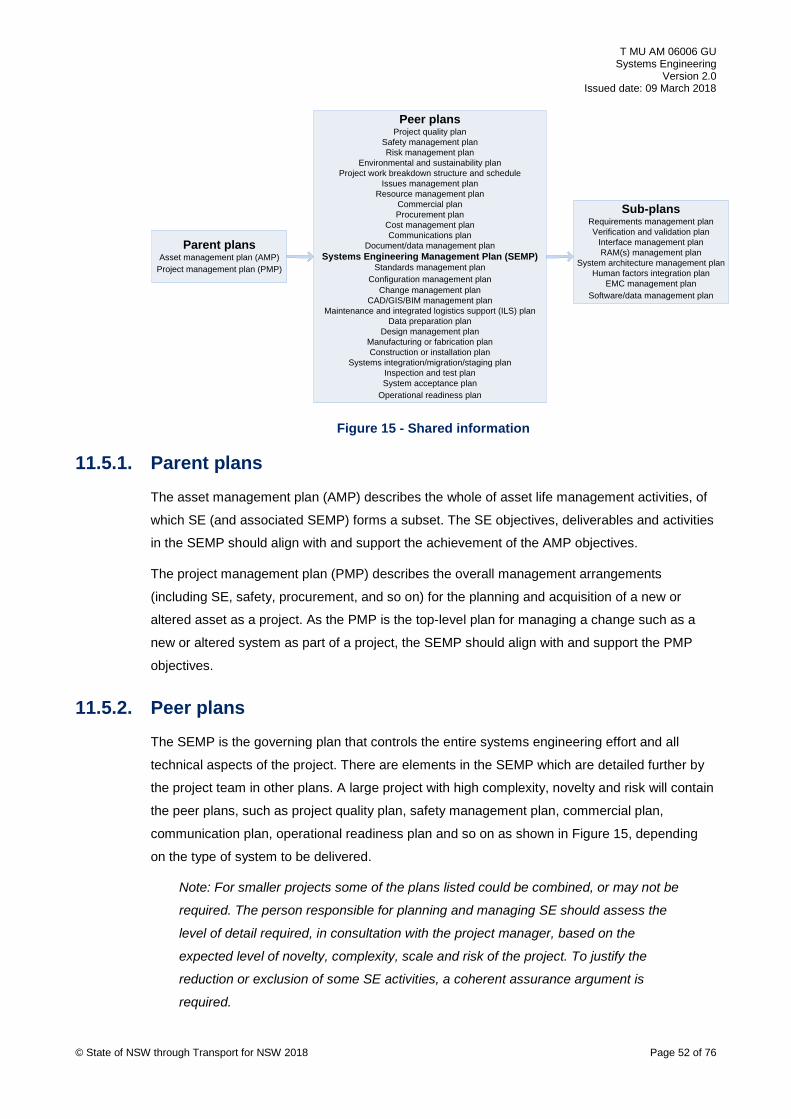
T MU AM 06006 GU Systems Engineering
Version 2.0 Issued date: 09 March 2018
Peer plans
Project quality planSafety management planRisk management plan
Environmental and sustainability planProject work breakdown structure and schedule
Issues management planResource management plan
Commercial planProcurement plan
Cost management planCommunications plan
Document/data management planSystems Engineering Management Plan (SEMP)
Standards management planConfiguration management plan
Change management planCAD/GIS/BIM management plan
Maintenance and integrated logistics support (ILS) planData preparation plan
Design management planManufacturing or fabrication planConstruction or installation plan
Systems integration/migration/staging planInspection and test planSystem acceptance plan
Operational readiness plan
Parent plansAsset management plan (AMP)
Project management plan (PMP)
Sub-plansRequirements management planVerification and validation plan
Interface management planRAM(s) management plan
System architecture management planHuman factors integration plan
EMC management planSoftware/data management plan
Figure 15 - Shared information
11.5.1. Parent plans The asset management plan (AMP) describes the whole of asset life management activities, of
which SE (and associated SEMP) forms a subset. The SE objectives, deliverables and activities
in the SEMP should align with and support the achievement of the AMP objectives.
The project management plan (PMP) describes the overall management arrangements
(including SE, safety, procurement, and so on) for the planning and acquisition of a new or
altered asset as a project. As the PMP is the top-level plan for managing a change such as a
new or altered system as part of a project, the SEMP should align with and support the PMP
objectives.
11.5.2. Peer plans The SEMP is the governing plan that controls the entire systems engineering effort and all
technical aspects of the project. There are elements in the SEMP which are detailed further by
the project team in other plans. A large project with high complexity, novelty and risk will contain
the peer plans, such as project quality plan, safety management plan, commercial plan,
communication plan, operational readiness plan and so on as shown in Figure 15, depending
on the type of system to be delivered.
Note: For smaller projects some of the plans listed could be combined, or may not be
required. The person responsible for planning and managing SE should assess the
level of detail required, in consultation with the project manager, based on the
expected level of novelty, complexity, scale and risk of the project. To justify the
reduction or exclusion of some SE activities, a coherent assurance argument is
required.
© State of NSW through Transport for NSW 2018 Page 52 of 76
T MU AM 06006 GU Systems Engineering
Version 2.0 Issued date: 09 March 2018
11.5.3. Sub-plans
The SEMP covers all of the major systems engineering functions and it may do so by referring
to other subordinate plans such as those shown in Figure 15 as 'sub-plans'. These sub-plans
focus on key technical and technical management processes for the project such as; human
factors, requirements, system architecture, interface management and configuration
management to name a few.
Note: For smaller projects some sub-plans could be combined (or form sections of a
SEMP), or may not be required. The person responsible for planning and managing
SE should assess the level of detail required, in consultation with the project manager,
based on the expected level of novelty, complexity, scale and risk.
12. Systems engineering technical processes A number of SE technical processes and related engineering management processes are
followed over the system life cycle. While this document intends to align broadly with the SE
technical processes defined in ISO15288, in practice within the transportation sector these
processes take on slightly different descriptions, interpretations and focus.
SE technical processes in ISO15288 are generically defined to cover a wide range of industry
sectors such as aerospace, defence, oil and gas, medical, automotive and transport.
For this reason, the generic ISO15288 processes are described in the context of how they will
be implemented in the transport sector, in particular for TfNSW. This is called tailoring.
12.1. Requirements definition process Requirements management (RqM) arrangements should be documented. Depending on the
scope, novelty, complexity and risk of the system to be delivered, RqM may be documented
based on the following levels:
• high: a standalone requirements management plan (RqMP)
• medium: a RqM section within a SEMP
• low: for simple projects that involve mostly a single discipline using type approved products
in a standard configuration, requirements management may be limited to a section of a
project plan or a project engineering management plan
Requirements management processes are used to define the requirements for a system to
achieve the following:
• transform the requirements into an effective system
• use the system to provide the required services
© State of NSW through Transport for NSW 2018 Page 53 of 76

T MU AM 06006 GU Systems Engineering
Version 2.0 Issued date: 09 March 2018
• sustain the provision of those services
• dispose of the system or system elements when it is retired from service
In order to achieve a new or altered service capability, the enterprise goals and needs are
identified by the sponsor developing service level agreements with operating agencies,
analysing customers' needs into requirements and transport planners. However, in some cases
it is possible that the operator and maintainer may perform this activity (for example, Sydney
Trains developing the Rail Operations Centre).
This activity is the trigger for the investment life cycle, and should align with the long term vision
and enterprise objectives of TfNSW and the State of NSW as a whole.
12.1.1. Business requirements The BRS is produced by the business unit responsible for strategic and transport planning, with
stakeholder input from the entities responsible for developing service level agreements,
analysing customers' needs, and operator and maintainer. In some cases the BRS may be
produced by the project delivery organisation. In other cases the operator and maintainer may
still encounter situations where it may lead to the development of the BRS (for example, Sydney
Trains specifying the ROC business requirements or NSW Light rail specifying Operations
Control Centre business requirements).
Regardless of who produces the BRS in any particular situation, the following activities should
be carried out in order to produce a baseline BRS:
• define the operational capability (operational performance) to support the need or goals
• produce an OCD that describes the operational activities required to support the
operational capability
• produce a MCD that describes the maintenance activities required to support the
operational capability
• produce a business case and associated BRS
• produce a ConOps that provides an overarching high-level view of the organisation, its
goals and objectives to direct the overall characteristics of the future business and systems
required to operate the business
• conduct all performance modelling and analysis to support production of these deliverables
The BRS should be accepted and endorsed by the TNAC to assure that network asset integrity
is retained in all these cases as it involves significant changes to the transport network.
Further guidance on developing a BRS can be obtained from T MU AM 06010 GU.
© State of NSW through Transport for NSW 2018 Page 54 of 76
T MU AM 06006 GU Systems Engineering
Version 2.0 Issued date: 09 March 2018
12.1.2. System requirements
The system requirements specification (SRS) is produced by the project delivery office often
with support from an experienced AEO acting as the technical advisor and with stakeholder
inputs obtained from the operator and maintainer and other TfNSW stakeholders as needed.
Depending on the commercial contract, the delivery organisation responsible for developing the
SRS may not always be the project delivery office within TfNSW.
In some cases the SRS may be produced by the operator and maintainer.
The following activities are carried out in order to produce an SRS:
• develop the concept design up to a (costed) reference design
• develop the SRS
• develop the P90 cost estimate
• prepare and issue an invitation to tender (ITT)
Further guidance on SRS is provided in T MU AM 06007 GU Guide to Requirements Definition
and Analysis.
12.2. Requirements analysis process When a tender is awarded, the contracting AEO(s) may choose to follow the reference design,
or to develop its own design, provided it meets the BRS and SRS requirements.
When a contract is awarded, the AEO should analyse the system requirements in the SRS, and
determine the appropriate system design solution to achieve these requirements. The AEO may
choose to adopt the reference design solution associated with the SRS, or it may choose to
develop its own solution.
As the system architecture evolves, the system requirements are allocated to subsystems such
as rolling stock vehicle, bus vehicle, road traffic signals, railway signalling and control,
telecommunications, electrical traction, track and structures. The allocation of requirements to
these subsystems results in the development of subsystem requirements that can be traced
back to system requirements.
The traceability of these requirements should be managed formally using a tool that is suitable
for the complexity of the new or altered system to be delivered.
The project should at all stages of the development of the new or altered system, be able to
trace the development of the design back to the key source documents that resulted in the
initiation of the project (for example, policy, strategy, long term plans).
© State of NSW through Transport for NSW 2018 Page 55 of 76

T MU AM 06006 GU Systems Engineering
Version 2.0 Issued date: 09 March 2018
The project should also be able to trace the development of the evolving system to informing
documents such as hazard logs, assumptions, dependencies, constraints, domain knowledge,
and value for money analysis.
For high-complexity projects that can contain a large number of requirements, a dedicated
commercial of the shelf (COTS) requirements management tool is recommended as it becomes
increasingly difficult for the following tasks:
• manage traceability and allocation of requirements as a system design evolves
• record all verification and validation evidence
• change requirements
• manage requirement baselines throughout the system acquisition phase
For lower complexity projects with fewer requirements and simpler interfaces, the requirements
may be managed in a spread sheet or similar tool (RATM/RVTM).
Various parts of TfNSW have taken a strategic decision to adopt a common RqM tool, schema
and process for seamless requirements management between the various divisions. The supply
chain should ensure that requirements under its control are defined in a common format that
permits easy exchange with TfNSW.
This common schema is defined in T MU AM 06004 ST Requirements Schema.
Further guidance is provided in T MU AM 06007 GU.
12.3. System architectural design process The system architecture forms the conceptual design framework, based on which detailed
system and subsystem design are based.
For systems involving high complexity, a functional architecture or model is good to start with to
ensure that all system functions are identified and sufficiently defined.
The system is further defined by identifying the proposed physical solution architecture and
allocating the functions to the physical system elements or subsystems.
The physical system elements or subsystems are then allocated to geographical locations to
form the geographical (or deployment) architecture.
Additional effort may be involved in defining system and subsystem interfaces as part of the
system architecture design process.
When the functional, physical, geographical and interface architecture design are defined, the
project then progresses to detailed design of each of the constituent subsystems as part of the
implementation process.
© State of NSW through Transport for NSW 2018 Page 56 of 76
T MU AM 06006 GU Systems Engineering
Version 2.0 Issued date: 09 March 2018
Examples of functional, physical, geographical and interface architectures that are synthesised
and developed under the system architectural design process are described in Section 7.6,
Section 7.7, Section 7.8 and Section 7.9.
Further guidance is provided in T MU AM 06001 GU Guide to System Architectural Design and
T MU AM 06003 TI Development of a Transport Network Architecture Model.
12.4. Implementation process The implementation process involves detailed design development of each of the subsystems,
specification and procurement of materials and OEM equipment, fabrication and manufacturing
at OEM supplier factory premises, shipping of fabricated material and OEM equipment to site,
and installation and assembly on site.
The level of SE within the implementation process is limited to verification of designs, factory
acceptance and site acceptance.
12.5. Interface and integration process Interface management is the collection of activities to ensure that discrete elements and
systems can function together. Systems integration involves bringing together component
elements or subsystems into one system, ensuring that they function together as a complete
system, and ensuring the new system integrates with the existing system of systems.
The requirements for system interface management and integration management is stated in
T MU AM 06006 ST.
12.5.1. Technical interface management The complex, multi-disciplinary nature of engineering projects and systems requires that
technical interfaces (and organisational and stakeholder interfaces) should be clearly defined,
along with their ownership and control.
Interfaces should be analysed and synthesised into the overall system design. For high novelty
and complexity systems, a dedicated interface management plan is required. For simpler
projects, interface management may be part of an engineering management plan.
In the SE management context, interface management refers to managing the technical system
interfaces, and is not limited to organisation or contract interfaces.
Technical interface requirements, as a type of system requirement, should be identified during
the definition of the system solution. This should be captured into a central repository that is
managed for change and verified that these requirements are met.
Interface requirements are identified and captured by functional and physical architecture
models and stakeholder meetings and interviews.
© State of NSW through Transport for NSW 2018 Page 57 of 76
T MU AM 06006 GU Systems Engineering
Version 2.0 Issued date: 09 March 2018
Interface requirements are managed by interdisciplinary design reviews and checks (IDR and
IDC) and following standards (where standards adequately define known interfaces).
When the system requirements are allocated to individual subsystems (and the specialist
disciplines responsible for designing each subsystem), the risk of individual subsystem designs
diverging from each other in terms of how they integrate into the wider system may exist.
Regular interdisciplinary design reviews and checks should be facilitated to ensure that
interfaces defined in the earlier system architecture are still achievable in terms of the required
functionality and performance.
Depending on the level of novelty and complexity, these interdisciplinary reviews could be
facilitated either by a design manager or by a dedicated interface manager for high complexity
systems.
Interface risks may include both safety and non-safety related risks. Technical system interface
risks may be identified during preliminary hazard identification (HazId), followed by a more
detailed interface hazard analysis (IHA).
All technical interface risks should be managed in the same way, by assigning controls and
owners to assure that the risks are controlled to a level that is reasonably practicable.
For high complexity systems, specification and planning of interface development and control
should follow a structured approach. This is achieved by identifying all key subsystems within
the overall system, and arranging them in a matrix of rows and columns. Each element of the
matrix represents a technical or system interface to be controlled. An example of an ICD matrix
is presented in Appendix F.
When all interfaces are identified in the ICD matrix (also called an N2 matrix), each interface
should be defined in terms of who is responsible for each end of that interface and who takes
the lead on assuring that interface. This is done using the interface control document (ICD).
High level functionality and performance requirements should be identified in the ICD.
As the system architecture progresses, and depending on the level of novelty, complexity and
risk, an interface requirement specification (IRS) may be required to further define the detailed
functional and performance requirements.
Examples of where this level of interface definition and control would be required include
interfacing a particular signalling interlocking product type to the Radio Block Centre (RBC) for
an ETCS-L2 application. Details of the data telegram and associated protocols would need to
be defined in the IRS, to allow the interlocking to communicate with the RBC unit.
The IRS is most suitable for electrical and electronic programmable systems that rely on
embedded software.
© State of NSW through Transport for NSW 2018 Page 58 of 76

T MU AM 06006 GU Systems Engineering
Version 2.0 Issued date: 09 March 2018
12.5.2. Systems integration management
Systems integration (including operational integration activities), while carried out on the right
hand side of the V life cycle model after installation and before commissioning, is an activity that
should be planned well in advance, on the left hand side of the V life cycle model.
Due to the complex nature of the live operational railway, especially with brown field projects, it
is not possible to integrate all systems in a single stage. A systems integration plan should take
the interfaces defined in the ICDs (and IRSs if necessary), to develop a series of planned
intermediate stages. This is done in order to bring the various subsystems together in a
controlled manner, including the specification of integration tests.
The system (and subsystem) designer should cooperate with the testing and commissioning
staff to plan the integration and testing activities, along with acceptance criteria.
During system integration, designers should be available to support testing and commissioning
staff to ensure that the original interface design intent is met, and to authorise changes required
as a result of issues that may arise during integration and testing.
With some systems, a significant amount of the system integration and testing may be carried
out off site at the supplier’s factory premises, as factory integration testing.
For high complexity projects it may not be possible to commission the entire new or altered
system into operation in one stage onto the rail network. The most practical approach used for
introducing new or altered assets, is to introduce elements of the system through a series of
interim configuration states or stage works under possessions. This stage works may be
described in a stage works plan or migration plan or integration plan.
These migration or interim configuration stages should be carefully planned, to ensure that the
right staff, processes, tools, equipment and assets are ready for staged integration and testing.
The systems integration and migration plan should be supported by a detailed schedule of
integration activities and controls.
Where the change introduced by an interim configuration state is assessed as significant, then it
may need to be escalated above the delivery organisation's CCB for approval by the TNAC as
an interim commissioned system (that is TNAC Gate 5). In most cases, interim configurations
are managed as a change through the local delivery organisation's CCBs.
Further guidance is provided in the T MU AM 06014 GU Guide to Systems Integration.
12.6. Verification and validation process While ISO 15288 separates the verification and validation (V&V) technical processes, this
document combines them as closely related activities.
V&V often use the same processes, tools and methods, but for achieving different assurance
outcomes at different stages in the project life cycle of the system. © State of NSW through Transport for NSW 2018 Page 59 of 76

T MU AM 06006 GU Systems Engineering
Version 2.0 Issued date: 09 March 2018
The verification process spans through the system life cycle from the specify phase through to
system integration, whereas validation is used as the final demonstration that the business
requirements are met for system acceptance.
Verification activities include modelling, simulation, mock-ups, design reviews, independent
checking and verification, inspection, testing, auditing and surveys. Depending on the level of
novelty and risk, early validation of business and system requirements using models, mock-ups
and simulations, prior to commencing detailed design may be performed.
Verification deliverables may include a verification plan (possibly a V&V plan, since validation is
managed with verification), and one or more verification reports (or V&V reports) depending on
system complexity, novelty of products and configuration, and number of migration stages. This
V&V plan should describe the process and methods to be used, V&V organisation and
responsibilities, the structure of expected V&V evidence, how this V&V evidence is captured (in
a tool), and planned deliverables (reports). For simpler projects, verification may be embedded
within the SEMP, engineering management plan or even the project management plan.
The organisation, roles and responsibilities for verification activities may be different to
validation activities. For software specific projects such as communication based interlocking
data sets or ATRICS system, a separate verification plan and report may be developed by a
verifier to examine the completeness, correctness and consistency of the software in
accordance to the system and subsystem level specifications. While it may be railway focused,
further information and guidance on V&V specific activities and roles can be found in
EN 50128:2001.
During the acquire stage, the V&V plan should undergo changes throughout the preliminary and
detailed design phases to document the required V&V activities such as systems integration
tests (SIT), site acceptance tests (SAT) and factory acceptance tests (FAT).
The verification process spans through the system life cycle from the concept and specify phase
through to system integration and testing.
Verification should begin as soon as the BRS is produced. This should be done in order to
begin demonstrating that business requirements are identified and defined that satisfy and are
traceable to original user needs (demand analysis) defined at the very beginning of the system
life cycle. For low complexity projects, this may be done through a RVTM spreadsheet.
Furthermore, during requirements definition (BRS and SRS), the project should determine the
V&V methods and criteria that may be used later to assure that requirements are achieved, the
responsible person for each activity, and when these activities are planned to take place.
TfNSW projects use a specialised requirements management tool to capture both requirements
information and evidence details of the verification activities that are used to progressively
assure that requirements are met during design, construction, testing and commissioning
stages.
© State of NSW through Transport for NSW 2018 Page 60 of 76
T MU AM 06006 GU Systems Engineering
Version 2.0 Issued date: 09 March 2018
TfNSW has adopted DOORS as its standard requirements management tool and has specified
and configured a schema in DOORS to manage verification activities and evidence. For low
complexity projects, a RVTM spreadsheet may be developed in lieu of a complex requirements
management system.
TfNSW does not mandate the use of any proprietary RqM tool (such as DOORS) on AEOs and
the supply chain, but does require all requirement and V&V information to be presented in a
structure that facilitates seamless transfer into the TfNSW DOORS project repository.
Further guidance is provided in T MU AM 06004 GU and TS 10506 AEO Guide to Verification
and Validation.
12.7. Transition process Within the TfNSW context, transition means the activities associated with transferring the
system into operational use, from the delivery project to the operator and maintainer, which is
achieved by the commissioning and operational readiness and integration activities. The
operational readiness report reflects the satisfactory completion of the following activities:
• all commissioning tests completed and successful
• all safety risks controlled or transferred to and accepted by the operator and maintainer
• operational processes and procedures updated
• operator manuals complete and provided
• maintenance manuals complete and provided
• operators trained and certified on the new system
• maintainers trained and certified on the new system
12.8. Operation process Project perspective and operator and maintainer perspective are the two aspects to operations
process, that systems engineering should consider.
During the plan, specify, develop and acquire phases of a new or altered system, the project
should consider the system operations over its full operational life time (operability and
operational availability analysis). This information should be captured through the project OCD
and updated as the system design matures.
Following acceptance of the new or altered system from the project, the operator and
maintainer should continue to manage the system and its configuration, including application of
SE management principles to ongoing operations.
© State of NSW through Transport for NSW 2018 Page 61 of 76
T MU AM 06006 GU Systems Engineering
Version 2.0 Issued date: 09 March 2018
12.9. Maintenance process Project perspective and operator and maintainer perspective are the two aspects to
maintenance process that systems engineering should consider.
During the plan, specify, develop and acquire phases of a new or altered system, the project
should consider the system maintenance over its full operational lifetime (maintainability and
logistic support analysis). This should include consideration of many different maintainability
aspects, such as, but not limited to, the following:
• standardisation and commonality of spares
• interchangeability between multiple asset owners
• accessibility considerations to the maintainable item
• special tools and test equipment required
• maintenance staffing levels and staffing requirements
• built-in-test (BIT) capability
• maintenance and fault diagnostic aids
• remote and predictive maintenance
• failure isolation
This information should be captured through the MCD that is developed early in the plan phase
of the life cycle and updated as the system design matures.
Following acceptance of the new or altered system from the project, the operator and
maintainer should continue to manage the system and configuration, including application of SE
management principles to ongoing maintenance.
12.10. Disposal process In the case of brown field projects, the decommissioning and disposal of life-expired or obsolete
systems is often planned, designed and executed concurrently with the planning, design and
installation of new or altered systems.
Disposal of systems is not carried out by the same organisation that introduced those systems
in the first place; often separate in time by decades of operations and maintenance.
12.11. Process mapping to the life cycle The SE processes described in Section 12, and other SE related engineering processes, are
active at different stages in the total system life cycle. Some processes may map to one or more
specific stages, whereas others may map and be active across the full life cycle. Additionally,
© State of NSW through Transport for NSW 2018 Page 62 of 76
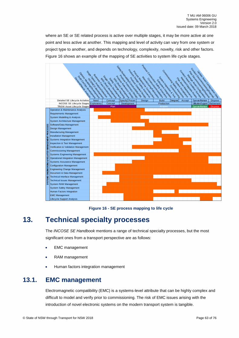
T MU AM 06006 GU Systems Engineering
Version 2.0 Issued date: 09 March 2018
where an SE or SE related process is active over multiple stages, it may be more active at one
point and less active at another. This mapping and level of activity can vary from one system or
project type to another, and depends on technology, complexity, novelty, risk and other factors.
Figure 16 shows an example of the mapping of SE activities to system life cycle stages.
Demand/Needs Analysis
Draft ConOps development
Options Modeling/Development
OCD/MCD development
Single Option Analysis/Selection
Business Case Development
BRS (final) development
Single Option Development
Safety Change Planning
SRS (final) development
Produce Reference Design
Produce Preliminary Design
Safety/Sutainaiblity/Constructibilty/VfM
Produce Detailed Design
Produce Design Safety Assurance
Procure Material for Construction
Manufacturing/Fabrication
Construction/Installation
Produce Construction Safety Assurance
Subsystem Integration
System Inspection & Test
Commissioning
Commissioning Safety Assurance
System Acceptance
Plan Asset Maintenance
Maintain/Upgrade Assets
Conduct Asset Condition Surveys
Manage Asset Configuration
Plan Decomm
issioning/Disposal
Conduct Decommissioning/Disposal
Update Asset Configuration Data
Operate/Maintain DisposeNeed Concept Specify Procure Build Integrate AcceptDesignDetailed SE Lifecycle ActivitiesINCOSE SE Lifecycle Stages
TfNSW Asset Lifecycle StagesOperation & Maintenance AnalysisRequirements ManagementSystem Modelling & AnalysisSystem Architecture ManagementSoftware/Data ManagementDesign ManagementManufacturing ManagementInstallation ManagementSystems Integration ManagementInspection & Test ManagementVerification & Validation ManagementCommissioning ManagementSystems Engineering ManagementOperational Integration ManagementSystems Assurance ManagementConfiguration ManagementEngineering Change ManagementDocument & Data ManagementTechnical Interface ManagementTechnical Issues ManagementSystem RAM ManagementSystem Safety ManagementHuman Factors IntegrationEMC ManagementLifecycle Support Analysis
DisposeOperate/Maintain
Operate/Maintain DisposeUtilisation/Support Retirement
SYST
EMS
ENGI
NEER
ING
& RE
LATE
D MA
NAGE
MENT
PRO
CESS
ES
Need Concept Specify
PlanDevelopment
ProcureExploratory Concept
Build Integrate Accept
AcquireProduction
Design
Figure 16 - SE process mapping to life cycle
13. Technical specialty processes The INCOSE SE Handbook mentions a range of technical specialty processes, but the most
significant ones from a transport perspective are as follows:
• EMC management
• RAM management
• Human factors integration management
13.1. EMC management Electromagnetic compatibility (EMC) is a systems-level attribute that can be highly complex and
difficult to model and verify prior to commissioning. The risk of EMC issues arising with the
introduction of novel electronic systems on the modern transport system is tangible.
© State of NSW through Transport for NSW 2018 Page 63 of 76
T MU AM 06006 GU Systems Engineering
Version 2.0 Issued date: 09 March 2018
Where type approved products are used in standard configurations, EMC may be demonstrable
by complying with engineering standards and codes of practice and some testing. Where novel
products are introduced or type approved products are configured in a novel way, then
additional modelling, analysis and testing is required in order to assure EMC risk is controlled.
The level of EMC effort should be scalable according to the novelty, complexity and risks
associated with the introduction of new or altered systems.
For an electrical traction supply engineer, EMC may relate to modelling and analysis of a novel
25 kV ac traction system introduced onto a section of the rail network that was previously using
1500 V dc traction, or was not electrified. The effects of electromagnetic induction on parallel
conductive paths such as fences, pipelines, and copper cables should be analysed and
appropriate EMC controls put in place.
For a signal engineer, EMC may relate to analysis of external EMI threats to signal interlocking,
remote control systems, copper lineside cables and other trackside equipment.
For a telecommunications engineer, EMC may relate to the introduction of audio hearing loops
on station platforms, close to traction OHW and train detection systems, and therefore the need
to analyse and test for in-band interference between these systems.
For a structural engineer, EMC may relate to the need to cooperate with the electrical traction
supply engineer in identifying earthing and bonding arrangements for a bridge and the effects of
electrolysis from dc traction earth return currents on the structure foundations.
For a contractor designing and building an at-grade car park outside the rail corridor, a need for
any form of EMC management may not be present.
For more detailed guidance on management of EMC, refer to TS 10504: 2013 AEO Guide to
Engineering Management and AS/RISSB 7722 EMC Management. For the purposes of railway
engineering, the EN 50121 series of standards are treated as the guiding standards.
13.2. RAMS management For the purposes of this guide, the term reliability, availability, maintainability and safety (RAMS)
is used to define an integrated management approach. However, this guide is limited to RAM
and not the safety element of RAMS management, as safety assurance is addressed in
T MU MD 20001 System Safety Standard for New or Altered Assets.
The need for and application of RAM management has different meaning to different disciplines.
The impact of RAM management on planning and acquisition of new or altered systems and the
specific disciplines that support the system design should be understood.
For a structural engineer, RAM may relate to finite element modelling and analysis of a bridge
structure to determine stress points and selection of corrosion-resistant materials to ensure that
the bridge meets or exceeds a 100 or 200-year lifetime.
© State of NSW through Transport for NSW 2018 Page 64 of 76

T MU AM 06006 GU Systems Engineering
Version 2.0 Issued date: 09 March 2018
For a track engineer, RAM may relate to the selection of harder wearing steel rail (such as CrMn
or head-hardened rail) to achieve longer wear life under increased axle loads. This will have
longer term impacts on future rail grinding and profiling programs that incur significant cost to
the operator and maintainer.
For an electrical traction supply engineer, RAM may relate to the modelling and analysis of the
traction power supply network, including feeders from the bulk electricity suppliers. This ensures
that all traction supply points to the railway are fed from at least two geographically diverse
sources. This is done in order to achieve a required power supply availability and traction
current performance under normal, degraded and emergency modes of operation.
For a signal engineer, RAM may relate to the reliability modelling and analysis of a redundant
remote control or interlocking architecture to assure availability or the selection of LED signals
to improve reliability over filament lamp signals.
For a telecommunications engineer, RAM may relate to reliability modelling and analysis of a
redundant optical fibre backbone network and selection of a ring, star or network architecture to
achieve sufficient network availability under degraded modes of operation.
Human element of overall system reliability should be considered in the development of a
system and the achievement of its requirements. Humans are susceptible to varying levels of
performance due to many factors that affect their reliability in carrying out functions, including
stress, fatigue, distraction, workload, environment, competence, and so on. Human factors can
assist with designing systems that take into account human capabilities and limitations, thus
improving reliability.
Where the new or altered system is specified to use proven type approved products in standard
approved configurations, the need for RAMS modelling may not be necessary. If the preferred
option is specified by TfNSW due to logistic reasons, then there is little value to be gained by
the AEO (typically the design consultant) performing detailed RAMS modelling and analysis in
order to obtain numeric RAMS targets. However, major changes to parts of the system require a
RAMS assessment to maintain or at least improve the integrity of the system.
Where TfNSW has provided numeric RAMS targets to be met by the contracting parties, then it
is necessary for the design AEO to develop a RAM model to verify during design that the
system is likely to meet those targets.
In order to achieve a system-level assurance of RAM, a RAM manager or engineer should
coordinate all individual RAM analysis performed at subsystem level where the level of system
complexity, novelty and risk justifies this.
For more guidance on the management of RAM, refer to the following standards:
• T MU AM 06002 GU AEO Guide to Reliability, Availability and Maintainability
• TS 10504: 2013 AEO Guide to Engineering Management
© State of NSW through Transport for NSW 2018 Page 65 of 76

T MU AM 06006 GU Systems Engineering
Version 2.0 Issued date: 09 March 2018
• EN 50126-1 Railway applications - The specification and demonstration of Reliability,
Availability, Maintainability and Safety (RAMS) - Part 1: Basic Requirements and Generic
Process
• AS/NZS ISO/IEC 15288 Systems and software engineering—System life cycle processes
13.3. HFI management The study of human factors and ergonomics and the interaction of humans with designed and
built systems is a complex and specialised field. This is carried out by specialist professionals
with the necessary blend of knowledge in human psychology, biomechanics and cognitive skills
to support the development of systems that successfully work with human operators.
The AEO should be aware of the need for human-system interaction in the development of the
system solution, in order to ensure an effective and efficient system, and provide assurance that
new risks (including safety) are not introduced at the human-machine interface.
For more detailed requirements and guidance on human factors integration, refer to the
following documents.
• T MU HF 00001 ST Human Factors Integration – General Requirements
• T HR HF 00001 ST Human Factors Integration – Rolling Stock
• T MU HF 00001 GU AEO Guide to Human Factors Integration
14. Related life cycle processes Depending on the scope, complexity, novelty, risk and contractual arrangements of a system
asset-related engineering project, relating the core SE technical processes to other related
processes, including the following is necessary:
• agreement processes
• organisational project-enabling processes
• project processes
• tailoring processes
14.1. Agreement processes Agreement processes include the acquisition process and supply process.
In the acquisition process, SE should communicate and coordinate efforts with TfNSW
procurement and its associated processes and ensure that system specifications are complete,
correct and coherent with the request for tender. The systems engineer may produce and
review tender specifications and review tender compliance to those specifications.
© State of NSW through Transport for NSW 2018 Page 66 of 76

T MU AM 06006 GU Systems Engineering
Version 2.0 Issued date: 09 March 2018
In the supply process SE should ensure that sufficient communication and coordination occurs
with the supply chain in terms of communicating system level requirements down to the
suppliers and ensuring that assurance of delivery against system requirements is provided by
suppliers.
14.2. Organisational project-enabling processes Management of SE to support the planning and acquisition of new or altered system requires an
understanding of, and interaction with, TfNSW enterprise-level processes to ensure that the
change is introduced within the overall enterprise management framework. These enterprise or
project-enabling processes include the following:
• life cycle model management process (TfNSW asset management framework)
• infrastructure management process (TfNSW asset management framework)
• project portfolio management process
• human resource management process
• quality management process (quality management system of TfNSW and agencies)
14.3. Project processes Management of SE on a project should be planned and carried out within the broader context of
other project management processes. The project processes that could have a direct interaction
with SE management processes include the following:
• project planning process (TfNSW project delivery process and operator and maintainer
project planning processes)
• project assessment and control process (TfNSW project delivery process and operator and
maintainer project control processes)
• project decision management process (TfNSW project delivery and operator and
maintainer project processes)
• project risk management process
• project configuration management process
• project information management process
• project measurement process
© State of NSW through Transport for NSW 2018 Page 67 of 76

T MU AM 06006 GU Systems Engineering
Version 2.0 Issued date: 09 March 2018
14.4. Tailoring processes Tailoring and scaling of the application of SE as defined in T MU AM 06006 ST to a project
should balance assurance of delivery of stakeholder and user requirements with value for
money engineering.
The person responsible for planning and managing SE should adopt a pragmatic, value for
money approach in implementing SE on a project. The systems engineer should assure delivery
of a new or altered system that meets the business and stakeholder requirements in the most
cost-effective manner.
If the project involves a system that uses type approved products in a standard configuration
that were successfully introduced before, then it is unnecessary to model RAM or EMC and the
level of human factors integration (HFI) may be limited.
Similarly, for a simple single-discipline project such as doubling the OHW contact wire to
achieve increased current capacity, the need to develop a system architecture model is
unnecessary.
15. SE tools The management of SE on high complexity and high novelty projects requires the selection and
implementation of appropriate tools to support various SE management activities.
These SE tools should be selected based on the value for money that they provide in improving
efficiency and assurance that the system requirements are complete, coherent and achieved.
Depending on the nature of the problem or need to be addressed by the acquisition of a new or
altered system, tools can be selected and implemented to support SE management as follows:
• requirements management tools
• system performance modelling tools
• system architecture visualisation and management tools
• safety case tools (such as using goal structuring notation)
• RAMS tools (such as FTA, RBD and FMECA)
• risk management tools
• human factors tools
• EMC modelling and analysis tools
• configuration management tools
• verification test management tools
• systems integration tools, including software and hardware integration tools © State of NSW through Transport for NSW 2018 Page 68 of 76

T MU AM 06006 GU Systems Engineering
Version 2.0 Issued date: 09 March 2018
Appendix A Example of SEMP structure A.1. SEMP structure
The SEMP should contain the following information, but not limited to:
• organisation of the project and how SE interfaces with other parts of the organisation
• responsibilities and authority of the key SE positions
• system boundaries and scope of the project
• assumptions, dependencies and constraints
• key technical objectives
• risk and opportunity plan, assessment, and methodology
• verification and validation planning
• configuration management planning
• QA planning
• infrastructure support and resource management (that is, facilities, tools, IT, personnel, and
so on)
• reliability, availability, maintainability, durability (for civils/structures) supportability, and
integrated logistics support (ILS)
• resilience (for global climatic change events, earthquakes, catastrophic fires and major
subsidence)
• EMC, radio frequency management, and electrostatic discharge
• human factors integration
• safety, health and environmental impact
• system security
• manufacturability or constructability
• test and evaluation
• testability and integrated diagnostics
• computer resources and SE tools
• transportability
• other engineering specialties that determine performance and functional requirements
© State of NSW through Transport for NSW 2018 Page 69 of 76

T MU AM 06006 GU Systems Engineering
Version 2.0 Issued date: 09 March 2018
Note: The SEMP structure obtained from INCOSE SE Handbook is modified to suit
TfNSW.
© State of NSW through Transport for NSW 2018 Page 70 of 76

T MU AM 06006 GU Systems Engineering
Version 2.0 Issued date: 09 March 2018
Appendix B Examples of SE application effort and scaling Table 2 identifies a range of typical transport engineering projects and the level of SE to be applied. The reader should note however, that there may be variations
on each of these scenarios, and engineering discretion is required in order to determine the scale of SE to apply.
Table 2 – Level of SE to be applied on rail engineering projects
Level Project Example Project Scale ($/time)
Complex Novelty Unmitigated project risk
SE effort
ReqM
Interface V&
V Sys A
rch R
AM
S EM
C
HFI
Project At-grade car park Small Low Low Low Light L L L L L - L Bus stop (single) Small Low Low Low Light L L L L L L L OHW (new/altered) Small Low Low Low Light L L L L L L - HV feeder 66/33/11 kV (new/altered) Small Low Low Low Light L L L L L M - Multi-story car park Medium Medium Low Medium Medium M M M L L - M Traction substation (single) Medium Medium Low Medium Medium M M H M M M M Station (small to medium, new/altered, single) Medium Medium Medium Medium Medium M M M M H M M Transport interchange or light rail stop (major, single) Large High Medium Medium Medium H H H M H M H Stabling yard (single) Large High Low Medium Medium H H H M H M H
Program Major track or road renewals (corridor/network) Large Low Low Medium Light L M M L M - - New bus fleet procurement Large Medium Medium Medium Medium M M M M H M H Transport access program (network) Large Medium Medium Medium Medium M H H M M L H Automatic train protection (network) Large High High High Heavy H H H H H H H New rolling stock fleet procurement (network/line) Large High High High Heavy H H H H H H H
Traction power supply upgrade (network) Large High Medium High Heavy H H H H H H M Signalling technology upgrade (network level – road and rail) Variable High High High Heavy H H H H H H H Corridor/line upgrade (brown field) V Large High High High Heavy H H H H H H H Corridor/line new build (green field) V Large High High High Heavy H H H H H H H
Portfolio Sydney's rail future (network/multiple programs) V Large V High V High V High Heavy H H H H H H H Sydney's Light rail future (CBD & SELR, Newcastle, Parramatta) V Large V High V High V High Heavy H H H H H H H Sydney's Ferry future (wharves and fleet) V Large V High V High V High Heavy H H H H H H H
© State of NSW through Transport for NSW 2018 Page 71 of 76

T MU AM 06006 GU Systems Engineering
Version 2.0 Issued date: 09 March 2018
Appendix C Specific and generic system life cycles Figure 17 and Figure 18 depicts the multiple system life cycles and V life cycle model for multi-disciplinary, staged rail engineering project, respectively.
Ops/Maint Concept
SRSSystem
Architecture
Demand Analysis
Business Case
BRSOptions Analysis
Preliminary Design
Detailed Design
AFC
Product Specification
Procure/ Manufacture
First Article Inspection
FAT
Site Installation
SAT
Systems Integration
SIT
(Client) Product Specification
Adapt Generic Product
SPECIFIC SYSTEM APPLICATION (TfNSW Project Delivery + D&C AEOs)
GENERIC PRODUCT DEVELOPMENT/ADAPTATION (Supplier AEOs)
Plan Product Development
Define Generic Product Reqts
Design Generic Product (System)
Develop/Adapt Generic Product
Integrate/Test Generic Product
(System)
Validate Generic Product
Accept Generic Product
Design Generic Product (Element)
Integrate Elements
Component Tests
Element Tests
Operational Readiness
System Validation
System Acceptance
Defects Liability
Minor Maint/ Upgrades
Minor Maint/ UpgradesSystem Validation
Generic Product Validation
Design Generic Product (Component)
Decommission/ Disposal
Verification
Verification
Verification
Verification
Verification
Verification
Verification
SYSTEM SUPPORT (OpCo AEO)
Verification
Verification
Verification
Verification
Verification
Verification
Verification
Verification
THESE V-DIAGRAMS ILLUSTRATE THE COMPLEX RELATIONSHIP BETWEEN A GENERIC PRODUCT
DEVELOPMENT/ADAPTATION LIFECYCLE, A SPECIFIC PROJECT APPLICATION LIFECYCLE, AND ONGOING SYSTEM/PRODUCT SUPPORT LIFECYCLE CHANGES
HW/SW Upgrades
HW/SW Upgrades
PRODUCT SUPPORT (Supplier AEOs)
GENERIC APPLICATION (TfNSW Project Delivery + AEO)
© State of NSW through Transport for NSW 2018 Page 72 of 76
Figure 17 – Multiple system life cycles

T MU AM 06006 GU Systems Engineering
Version 2.0 Issued date: 09 March 2018
Demand Analysis
Procure/ Manufacture
Defects Liability
OHW ELE COM SIG
System Validation
Verification
Verification
Verification
SAT/Inspection
Systems Integration
SIT
Operational Readiness
System Validation
System Acceptance
First Article Inspection
FAT
Site Installation
Ops/Maint Concept
SRSSystem
Architecture
Business Case
BRSOptions Analysis
Preliminary Design
Detailed Design
AFC
Product Specification
Verification
Verification
Verification
Verification
Verification
CIV TRK
© State of NSW through Transport for NSW 2018 Page 73 of 76
Figure 18 – V life cycle model for multi-disciplinary, staged rail engineering project
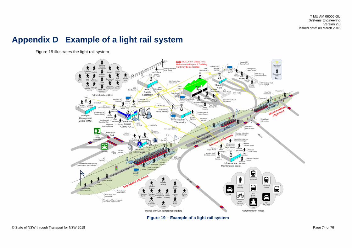
T MU AM 06006 GU Systems Engineering
Version 2.0 Issued date: 09 March 2018
Appendix D Example of a light rail system Figure 19 illustrates the light rail system.
Separated Alignment
Internal (TfNSW cluster) stakeholders Other transport modes
External stakeholders
Bulk Supply
SubstationHV Feeders
Stabling Yard
Operations Control
Centre (OCC)
InfrastructureMaintenance Depot
Fleet Depot
Traction Substation
Electrical Bulk Supplier Transmission Grid
TelecomMaintainer
SignalMaintainer
InfraControl
ElectricalOperator
NetworkMgmt
TelecomMaintainer
Signal Maintainer
Track Maintainer
CivilMaintainer
ElectricalMaintainer
YardSecurity
Yard OpsStaff
YardManager
FleetMaintainer
DepotSecurity
DepotOps StaffFleet
Depot Manager
Passenger
Driver
Guard
UnauthorisedPerson on track
Security
AuthorisedPerson on track
Staff Protection
DutyManager
Security
Protection of staff on track
OCC-LRV
OCC-Traction Sub
Manage Fleet Depot Control Fleet Depot
Movements
Fleet Depot Security Ops
Coordinate LR Infra Maintenance
LR Network Electrical Switching
Manage LR Network
Manage LR Network Security
Coordinate LR Signalling Maint
Coordinate LR Telecom Maint
Maintain Signal Assets
Maintain Telecom Assets
Authorised activities (survey, install, inspect, test, maintain...)
Use LR services
LRV & LR StopOperations
LRV & LR Stop Security Ops
Driving Ops
LRV Stabling Yard Security Ops
Manage LRV Driver Roster
LRV Stabling Yard Movements
Manage LRV Stabling Yard
Yard-Fleet Depot
LRV-Fleet Depot
LRV-Yard
Traction Substation-Infra Maint Depot
Threaten self-harm, trespass, vandalism, theft, terrorism
AmbulanceServices
PoliceService
FireService
HazMat
SES
Rail/RoadAccident
Investigators
Electrical Bulk Supplier
(3rd Party)
Manage Electrical Bulk Supply
Local Traction
Operator
Local Control of Traction Supply
OCC-Fleet Depot
OCC-Bulk Supplier
OCC-LR Stop
Maintain Track Assets
Maintain Civil/Structural Assets
Key
Operational Interface
OperationalRole
Revenue Protection
OCC-Infra Maint Depot
Maintain Electrical Assets
OHW
LR Signals
LR Stop/Interchange
RevenueProtection
Bus
Heavy Rail
Rail Rapid Transit
Active Cycleway
Active Walkway
Ferry
Taxi
Car (Car Parks)
ONRSR Inspectors
PowerUtilities
CountryRail
LocalCouncil
Industry
Commerce/Retail
Domestic/Residential
TransportPlanning
SydneyMetro
NSWTrains
Sydney Trains
Freight
FinanceInvestment
TransportServices
ProgramDelivery
CustomerService
Traction feed
Bulk Supply Sub-Traction Sub
EnviroProtection
HeritageWorkCoverInspectors
StateTransit
Authority
NSWTourism
OCC-Yard
Segregated Rail Alignment
Road
Alignment SeparationRail Alignment
Road Alignment
LR Stop
Road/Rail Alignment
Bus Rapid Transit
Segregated Alignment
Mixed road/rail
Alignment
Road
LR Stop PALR Stop
CIS
CLR StopSecurity CCTV
Bus Stop
Train Station/
Interchange
Collect Revenue
RevenueCollection
ATS/OPAL
Commuter Car Park
Security
Security of staff and assets
LR StopLighting
InfrastrNSW
NSWGovt
Note: OCC, Fleet Depot, Infra Maintenance Depots & Stabling Yard may be co-located
Road/RailIntersection
Road/RoadIntersection
CDepot
Security CCTV
Fleet Depot SecurityLighting
Traction Sub Security Lighting
CSub
Security CCTV
CYard
Security CCTV
Stabling Yard SecurityLighting
LR StopPHP
COCC
Security CCTV
TransportManagementCentre (TMC)
OCC-TMC
TransportManagement
Centre
IncidentManager
TransportCoordinator
PedestrianMaintain Fleet Assets
Passenger (LR user)
LR Signals
Pedestrian(non-LR user)
Passenger
LR Stop
Infrastructure Maintenance
Depot Manager
Manage Infrastructure Maintenance Depot
© State of NSW through Transport for NSW 2018 Page 74 of 76
Figure 19 – Example of a light rail system

T MU AM 06006 GU Systems Engineering
Version 2.0 Issued date: 09 March 2018
Appendix E TfNSW asset classification scheme Figure 20 shows the TfNSW asset classification scheme that is extracted from T MU AM 02002 TI Asset Classification System.
© State of NSW through Transport for NSW 2018 Page 75 of 76
Figure 20 – TfNSW asset classification scheme)

T MU AM 06006 GU Systems Engineering
Version 2.0 Issued date: 09 March 2018
Appendix F Example of interface control document matrix Figure 21 shows an example of the interface control document matrix.
ICD MATRIX Signalling Systems
Telecoms & Data Network
Control Systems
Electrical Substation
Overhead Wiring Track Systems General
CivilsBridges & Structures
Stations & Interchanges
Yards & Depots
Rolling Stock
ICD Code: 1.01 1.02 1.03 1.04 1.05 1.06 1.07 1.08 1.09 1.10Administration: ABC Entity ABC Entity ABC Entity ABC Entity ABC Entity ABC Entity ABC Entity ABC Entity ABC Entity ABC EntityDocument No.: XXX-ICD-10 XXX-ICD-11 XXX-ICD-12 XXX-ICD-13 XXX-ICD-14 XXX-ICD-15 XXX-ICD-16 XXX-ICD-17 XXX-ICD-18 XXX-ICD-19
Owner: Joe Bloggs Joe Bloggs Joe Bloggs Joe Bloggs Joe Bloggs Joe Bloggs Joe Bloggs Joe Bloggs Joe Bloggs Joe BloggsICD Code: 2.01 2.02 2.03 2.04 2.05 2.06 2.07 2.08 2.09
Administration: ABC Entity ABC Entity ABC Entity ABC Entity ABC Entity ABC Entity ABC Entity ABC Entity ABC EntityDocument No.: XXX-ICD-20 XXX-ICD-21 XXX-ICD-22 XXX-ICD-23 XXX-ICD-24 XXX-ICD-25 XXX-ICD-26 XXX-ICD-27 XXX-ICD-28
Owner: Joe Bloggs Joe Bloggs Joe Bloggs Joe Bloggs Joe Bloggs Joe Bloggs Joe Bloggs Joe Bloggs Joe BloggsICD Code: 3.01 3.02 3.03 3.04 3.05 3.06 3.07 3.08
Administration: ABC Entity ABC Entity ABC Entity ABC Entity ABC Entity ABC Entity ABC Entity ABC EntityDocument No.: XXX-ICD-30 XXX-ICD-31 XXX-ICD-32 XXX-ICD-33 XXX-ICD-34 XXX-ICD-35 XXX-ICD-36 XXX-ICD-37
Owner: Joe Bloggs Joe Bloggs Joe Bloggs Joe Bloggs Joe Bloggs Joe Bloggs Joe Bloggs Joe BloggsICD Code: 4.01 4.02 4.03 4.04 4.05 4.06 4.07
Administration: ABC Entity ABC Entity ABC Entity ABC Entity ABC Entity ABC Entity ABC EntityDocument No.: XXX-ICD-40 XXX-ICD-41 XXX-ICD-42 XXX-ICD-43 XXX-ICD-44 XXX-ICD-45 XXX-ICD-46
Owner: Joe Bloggs Joe Bloggs Joe Bloggs Joe Bloggs Joe Bloggs Joe Bloggs Joe BloggsICD Code: 5.01 5.02 5.03 5.04 5.05 5.06
Administration: ABC Entity ABC Entity ABC Entity ABC Entity ABC Entity ABC EntityDocument No.: XXX-ICD-50 XXX-ICD-51 XXX-ICD-52 XXX-ICD-53 XXX-ICD-54 XXX-ICD-55
Owner: Joe Bloggs Joe Bloggs Joe Bloggs Joe Bloggs Joe Bloggs Joe BloggsICD Code: 6.01 6.02 6.03 6.04 6.05
Administration: ABC Entity ABC Entity ABC Entity ABC Entity ABC EntityDocument No.: XXX-ICD-60 XXX-ICD-61 XXX-ICD-62 XXX-ICD-63 XXX-ICD-64
Owner: Joe Bloggs Joe Bloggs Joe Bloggs Joe Bloggs Joe BloggsICD Code: 7.01 7.02 7.03 7.04
Administration: ABC Entity ABC Entity ABC Entity ABC EntityDocument No.: XXX-ICD-70 XXX-ICD-71 XXX-ICD-72 XXX-ICD-73
Owner: Joe Bloggs Joe Bloggs Joe Bloggs Joe BloggsICD Code: 8.01 8.02 8.03
Administration: ABC Entity ABC Entity ABC EntityDocument No.: XXX-ICD-80 XXX-ICD-81 XXX-ICD-82
Owner: Joe Bloggs Joe Bloggs Joe BloggsICD Code: 9.01 9.02
Administration: ABC Entity ABC EntityDocument No.: XXX-ICD-90 XXX-ICD-91
Owner: Joe Bloggs Joe BloggsICD Code: 10.01
Administration: ABC EntityDocument No.: XXX-ICD-100
Owner: Joe BloggsICD Code:
Administration:Document No.:
Owner:
Overhead Wiring
Track Systems
General Civils
Rolling Stock
Signalling Systems
Telecoms & Data Network
Bridges & Structures
Stations & Interchanges
Yards & Depots
Control Systems
Electrical Substation
© State of NSW through Transport for NSW 2018 Page 76 of 76
Figure 21 – Example of interface control document matrix