Embed Size (px)
Citation preview

Transaction
Paper
Introduction
Pilot plant testing of the Mintek ThermalMagnesium Process (MTMP) was carried outin the period 2001–2004. The work consistedof 10 campaigns (Runs), each with its ownobjectives and plans. Between campaigns,certain equipment changes and modifications,and installations of new equipment, wereimplemented. These changed were guided bythe experience gained in earlier campaigns andby theoretical modelling around the newequipment, particularly the condenser. Themodelling incorporated momentum, energy,and mass transfer phenomena, including metalvapour condensation in the presence andabsence of inert gas (argon). Thermodynamicsimulations were also employed for feed recipemanipulation and changes, and for theoreticalenergy balance calculations around the furnaceand the condenser.
In each run, progress was made in terms ofimproved operability of the pilot plant, andtherefore improved metallurgical results,particularly with regard to the condensationefficiency of the volatilized magnesium. This
paper highlights the major changesundertaken throughout the testwork that led tothe successful demonstration of the process atthe pilot scale in 2004. In addition, the majoroperational and metallurgical results of eachrun are summarized and briefly discussed.
Background to the MTMP
The MTMP is an advance on the silicothermictechnology for magnesium production fromcalcined dolomite (dolime). In the Mintekprocess, a DC open arc furnace is employedand the reaction is carried out at atmosphericpressure and at 1700–1750°C. The MTMP canbe carried out in a much more continuousmode than the Magnetherm process, as thevolatilized magnesium is recovered as liquidmetal in a separate condenser vessel. Slag andsome residual ferrosilicon are periodicallytapped from the furnace, and magnesium istapped from the condenser, also intermittently.
The MTMP was initially proven at the40–80 kW scale in the 1980s wheremagnesium extraction and condensation atatmospheric pressure were demonstrated1–2.The project was revived in 1999 when AngloAmerican Corporation (AAC), Eskom, andMintek decided to pursue the concept at thepilot scale. During the scoping study, it wasdecided to use the Magnetherm condenser asthe basis for the design of the pilot condenseras it was a proven technology, in spite of thefact that Magnetherm process operated oncyclic basis of 10–12 hours each. Therefore,the original objective of the MTMP plant wasto extend the cycle time to 20 hours of ‘feedon’ time. This was later increased to 36 hoursfor Runs 6–8, and finally to 48 hours for Runs9–10. The scoping study also concluded that to
Review of the development work on theMintek Thermal Magnesium Process(MTMP)by M. Abdellatif*
SynopsisThe Mintek Thermal Magnesium Process (MTMP) process is basedon DC open arc metallothermic smelting of calcined dolomite atnormal pressure and temperatures of 1650–1750°C. The process wasdemonstrated at the pilot scale in the period 2000–2004. Majorchanges to the MTMP pilot plant were made throughout thedevelopment period, which lasted for about five years. The changesincluded design and installation of new equipment, modification ofexisting equipment, changes in the metallurgical approach in termsof feed rates, feed recipes, furnace operating temperatures, cold andhot dolime feeding, and steady and systematic changes in theoperating procedures and maintenance of the plant.
As a result, the performance of the pilot plant graduallyimproved from one campaign to the next, in terms of availabilityand in particular the condensation efficiency. In Run 10, the processwas successfully demonstrated over an 8-day campaign.
KeywordsMagnesium, condensation efficiency, DC arc furnace, silicothermicreduction.
* Mintek, Johannesburg, South Africa.© The Southern African Institute of Mining and
Metallurgy, 2011. SA ISSN 0038–223X/3.00 +0.00. Paper received Mar. 2010; revised paperreceived Mar. 2011.
393The Journal of The Southern African Institute of Mining and Metallurgy VOLUME 111 JUNE 2011 ▲
text:Template Journal 7/6/11 15:12 Page 393

Review of the development work on the Mintek Thermal Magnesium Process (MTMP)
successfully complete the development work could requirethree years. In reality, the project lasted for about five yearsas a result, in part, of extensive and major changes in thedesign of the pilot plant, particularly the condenser and itsperipheral equipment. These changes were considerednecessary in order to be able to operate the MTMP plant on amore continuous basis, as compared to the Magnethermprocess.
Pilot plant description
The pilot plant was described in earlier publications3–8. Itconsisted of a feed system, a 1.5 MW DC power supply, a 1.2 m ID furnace, a condenser with a heating-cooling leadcircuit, and an off-gas handling system. In Runs 1–9, thecondenser design was based mostly on the Magnethermprocess as it was a proven technology (Figure 1). Figure 2shows the pilot plant as employed in Run 10.
Throughout the testwork, the feed system and thefurnace performed very well and therefore no major changeswere made. The condenser and the off-gas system, on theother hand, were progressively modified, as a means ofincreasing the plant ‘feed on’ availability, and thus toimprove on the operational and metallurgical results of theprevious runs, as will be shown later.
Testwork
In Runs 1–3, the overall objective was to process 500–600 kgof magnesium-producing recipe (Table I), and thus to givethe staff involved sufficient opportunity to become familiarwith the plant and the operating procedures, and moreimportantly to gain experience in magnesium production andits safe handling.
In the first two runs, the dolime was charged into thefurnace as received. In Run 3, however, it was preheated to750°C in an electrically heated kiln in order to remove anysurface moisture and residual carbon dioxide, and thenstored in sealed drums under argon atmosphere (as well as inRuns 4–6). Run 3 also excluded the magnesia from the feed.The feed recipe and feed rate were aimed at producing about80 kg Mg(v) per hour. The original lead circuit was relied onto control the condenser temperatures in these three runs (aswell as in Runs 4–5). However, attaining the targettemperature of 600–650°C on the crucible sidewalls wasdifficult.
As shown in Table I, very little condensation took placeinside the condenser crucible. This was attributed to variousfactors, including oxygen lancing, air ingress, short feedingperiods, and the relatively cold condenser due to difficultiesencountered with the lead circuit. The condensation efficiencywas defined as: {Mg in crude metal/Mg extracted}*100%,where Mg extracted was determined from: {(Mg in feed-Mg inslag)/Mg in feed}*100%.
These runs were abandoned as a result of pressure build-up in the facility caused by blockages (mostly Mg/MgOpowder) in the off-gas system. In the first run, the blockagewas in the U-tube (argon reservoir) and the hot filter.Therefore, prior to Run 2, they were replaced by largerducting connecting the gooseneck to the combustion chamber(Figure 3). In Run 2, the blockage was mainly in the
horizontal section of the argon reservoir, although build-upof solids occurred to some extent in the secondary condenserand the gooseneck areas. Similar experiences wereencountered in Run 3.
Runs 4 and 5 aimed at producing 200–300 kg of crudemagnesium. This called for feeding about 2 tons of rawmaterials (Table II). In preparation for Run 4, the cross-sectional area of the gooseneck was increased from 100cm2
to 325 cm2 in order to prevent premature blockages in thissection. About 2 tons (two batches) of Mg recipe was smeltedover a 5-hour feeding period, producing a magnesium ingotweighing almost 200 kg. Attempts to recover the ingot fromthe crucible were not successful and led to a magnesium firein the crucible. The crucible contents were therefore reactedwith 10% NaOH solution and then with sulphuric acid as ameans of oxidizing the metallic magnesium present.Nevertheless, a condensation efficiency of more than 50%was reached in this run, and magnesium extraction wasbetween 82–87%.
▲
394 JUNE 2011 VOLUME 111 The Journal of The Southern African Institute of Mining and Metallurgy
Figure 1—Schematic of the initial pilot plant—Run 1
Figure 2—Schematic of the pilot plant—Run 10
text:Template Journal 7/6/11 15:12 Page 394
Prior to Run 5, a comprehensive review of the pilot plantand the operating procedures was undertaken. As a result, adedicated cleaning station was built in order to safelypassivate reactive products that formed inside the condenserand the off-gas system. In addition, a modified argonreservoir and gooseneck were designed and installed (Figure 4). The argon reservoir was 200 mm ID, while thegooseneck was replaced with a straight duct (300 mm ID).Prior to the run, the baffle plate inside the secondarycondenser was removed.
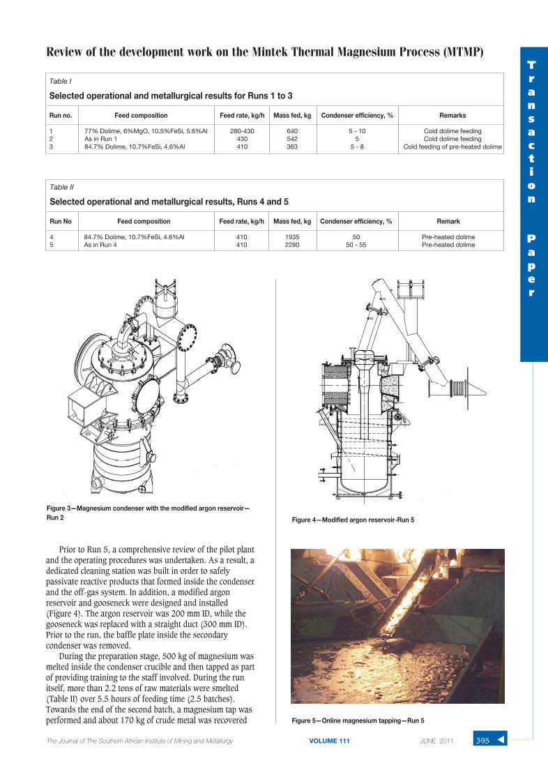
During the preparation stage, 500 kg of magnesium wasmelted inside the condenser crucible and then tapped as partof providing training to the staff involved. During the runitself, more than 2.2 tons of raw materials were smelted(Table II) over 5.5 hours of feeding time (2.5 batches).Towards the end of the second batch, a magnesium tap wasperformed and about 170 kg of crude metal was recovered
Review of the development work on the Mintek Thermal Magnesium Process (MTMP)Transaction
Paper
395The Journal of The Southern African Institute of Mining and Metallurgy VOLUME 111 JUNE 2011 ▲
Table I
Selected operational and metallurgical results for Runs 1 to 3
Run no. Feed composition Feed rate, kg/h Mass fed, kg Condenser efficiency, % Remarks
1 77% Dolime, 6%MgO, 10.5%FeSi, 5.6%Al 280-430 640 5 - 10 Cold dolime feeding 2 As in Run 1 430 542 5 Cold dolime feeding3 84.7% Dolime, 10.7%FeSi, 4.6%Al 410 363 5 - 8 Cold feeding of pre-heated dolime
Figure 3—Magnesium condenser with the modified argon reservoir—Run 2
Table II
Selected operational and metallurgical results, Runs 4 and 5
Run No Feed composition Feed rate, kg/h Mass fed, kg Condenser efficiency, % Remark
4 84.7% Dolime, 10.7%FeSi, 4.6%Al 410 1935 50 Pre-heated dolime5 As in Run 4 410 2280 50 - 55 Pre-heated dolime
Figure 4—Modified argon reservoir-Run 5
Figure 5—Online magnesium tapping—Run 5
text:Template Journal 7/6/11 15:12 Page 395

Review of the development work on the Mintek Thermal Magnesium Process (MTMP)
from the condenser crucible (Figure 5). In addition, about200 kg of metal was collected when the crucible was treatedwith molten salt mixture.
This run, as well as Run 4, clearly demonstrated thatmagnesium condensation at atmospheric pressure wasfeasible, even in the presence of inert gas (argon with a totalflow rate of 40–50 l/min). The calculated condensationefficiency during Run 5 was between 50–55%. Equallysignificant was the ability to carry out on-line magnesiumtapping for the first time.
The relatively low condensation efficiency obtained inRuns 1–5 were related to various factors including: 1) Airingress and subsequent oxidation of the volatilizedmagnesium during the operation. This was evident in certainoccasions where some of the condenser products contained0.1–2.0% N2. 2) Low condenser temperatures, particularly atthe beginning of the run, resulting in the formation ofmagnesium powder as well as dendrites. Upon dismantlingthe condenser for cleaning, such products reacted with air toform oxides and, to a lesser extent, nitrides of magnesium.3) Oxygen lancing for furnace slag tapping. This led tooxidation of residual magnesium vapour in the system,magnesium powder and dendritic magnesium. 4) Magnesiumvapour losses due to back reactions with residual CO2 andmoisture in the feed, as well as with CO formed as a result ofthe reaction between the graphite electrode and the furnaceslag.
Thorough evaluation of the metallurgical and operationaldata highlighted the need for increasing ‘feed on’ availabilityand the condensation efficiency over a ‘feed on’ period of 36hours and more. Therefore, it was decided to design andinstall a drill machine and mud gun assembly for furnacetapping (Figure 6), and to remove the slag ladles as quicklyas possible by placing them on a sliding plate. Doing soallowed sealing of the furnace taphole and thus fasterresumption of feeding into the furnace. In addition, amechanical plunger was installed on the horizontal section ofthe argon reservoir as a means of removing solid build-up inthis area. For operational and safety considerations, the leadcircuit was modified prior to Run 6, whereby the leadreservoir and pump were relocated away from the condenser.
These changes were implemented prior to Run 6, andcontributed to the higher condensation efficiency reached inthis run (Table III), as well as to increased ‘feed on’availability from about 5 hours in the previous run to about10 hours.
In Run 7, the dolime was heated directly to 700–750°C ina dedicated heating station that employed two diesel burnersand charged hot into the feed system and subsequently intothe furnace (Figure 7). The objective was to minimize anyresidual CO2 (as well as any surface moisture), and therefore
to improve the condensation efficiency. For Run 7 and Run 8,the lead jacket around the crucible was replaced by a leadtank as a result of mechanical difficulties. The tank coveredthe bottom half of the crucible. In addition, propane burnerswere used to heat the upper sides of the crucible in anattempt to maintain the condenser temperatures at600–650°C.
However, the results obtained suggested that the conden-sation efficiency was lower than that reached in the previousrun, although the ‘feed on’ period was similar. It is believedthat during the heating of the dolime, carbon deposition tookplace, particularly in the colder regions of the vessel. Thiscarbon reacted with the MgO in the slag, generating carbonmonoxide, which back reacted with Mg(v), resulting inmagnesium losses, and more importantly with the deposition
▲
396 JUNE 2011 VOLUME 111 The Journal of The Southern African Institute of Mining and Metallurgy
Figure 6—The mud gun -and drill machine—Run 6
Figure 7—Dolime pre-heating station
Table III
Selected operational and metallurgical results, Runs 6 to 8
Run no. Feed composition Feed rate, kg/h Mass fed, kg Condenser efficiency, % Remarks
6 84.7% Dolime, 10.7%FeSi, 4.6%Al 410 3990 47 - 61 Pre-heated dolime7 As in Run 6 410 4020 45 Hot dolime feed-diesel8 83.7% Dolime, 10.6%FeSi, 5.5%Al 415 4085 55 - 75 Hot dolime feed, rotary kiln
text:Template Journal 7/6/11 15:12 Page 396

of carbon in the condenser. This led to high levels ofmagnesium losses in the form of small metallic globules(oxides and salt fluxes) that were trapped within the sludge.Inclusion of aluminium fluoride in the salt flux did notimprove the metal recovery from the dross. Therefore, thereported condenser efficiency was lower than that achieved inRun 6.
In order to avoid carbon deposition and to ensure moreuniform heating of the dolime, an electrically operated kilnwas employed to raise the dolime temperature to 650–750°C.The dolime was then transferred to the feed system andcharged hot into the furnace (typically at 500–650°C). Doingso resulted in a condensation efficiency of up to 75% in Run8 (Table III), which lasted for about 10 hours of ‘feed on’time. During the run, a few on-line magnesium taps werecarried, ranging from 60–110 kg Mg each. In this run, thealuminium addition into the furnace was increased to about5.5% of the total feed in order to produce a more fluid slagcontaining 12–13% Al2O3 for easier and faster furnacetapping.
In spite of the various operational, metallurgical, andmechanical improvements in the previous three runs,blockages in the system persisted and limited the ‘feed on’time to only about 10 hours. The blockages occurred mostlydownstream of the condenser, and build-up of solids wasalso evident in the furnace off-gas duct. In addition, thecondenser crucible tended to contain a mixture of dross(mostly MgO) and metallic globules, making it difficult to tapthe condensed magnesium promptly.
These findings highlighted the need for redesigning theargon reservoir (Figure 8) and the installation of twomechanical plungers on the furnace off-gas and the argonreservoir respectively prior to Run 9. The total feed rate to thefurnace was increased by about 25% (Table IV) in an attemptto generate about 100 kg Mg(v)/h. The higher magnesiumvapour production rate was intended to provide more energyof condensation into the condenser crucible, and thus toenable tapping of the liquid metal. The dolime was heated inthe rotary kiln as in the previous run.
The changes contributed to doubling the feeding period(from 10 hours in Runs 6–8, to about 20 hours in Run 9).During the run, five on-line magnesium taps weresuccessfully performed, yielding more than 500 kg of crudemetal. Co-melting of the crucible contents with salt mixtureled to the recovery of about 400 kg of magnesium. Thecalculated magnesium condensation efficiency ranged from75–80%, which was the highest value obtained thus far. Inaddition to the improved efficiency, the crude metal wasproperly assessed with good confidence for the first time,particularly with respect to detrimental impurity elementssuch as Ca, Si, Fe, and Mn. The levels of such elements in theproduced metal were generally lower than those of theMagnetherm crude magnesium9.
However, build-up of solids continued to be a majorchallenge, particularly in the connection between the argonreservoir and gooseneck area (which led to a major blockage)and in the furnace off-gas duct. Failure of the rubber tubeseal towards the end of the run contributed to such build-up.These difficulties limited the run duration to 20 hours, ascompared to the target of 48 hours.
Another outcome of Run 9 (as well as Run 8) was thedifficulty of keeping the condenser product molten for prompttapping of the metal. This was related to two major factors:the relatively low condenser temperatures as a result of in-effective and non-uniform heating of the crucible, and to theformation of alternating layers of magnesium andmagnesium oxide (Figure 9). In Run 9, lead circulation wasnot used. Instead, the lead tank (filled with molten lead) washeated using a 250 kW propane burner. The burner wasinstalled underneath the crucible.
During feeding, and Mg(v) generation, magnesiumcondensed mostly to the liquid state forming a molten layer.Some of the volatilized metal condensed as powder in colder
Review of the development work on the Mintek Thermal Magnesium Process (MTMP)Transaction
Paper
The Journal of The Southern African Institute of Mining and Metallurgy VOLUME 111 JUNE 2011 397 ▲
Figure 8—Mintek pilot condenser with lead tank—Run 9: 1. Condenserinlet, 2. Condenser crucible, 3. Liquid magnesium, 4. Magnesiumtaphole, 5. Tank with liquid lead, 6. Condenser elbow, 7. Condenseroutlet pipe (stinger), 8. Plunger, 9. Gooseneck, 10. Pressure relief disk,11. Argon reservoir, 12. Flap valve, 13. Combustion chamber, 14. Plunger, 15. Off-gas connection to fan and stack
Figure 9—Cross-section of the condenser after Run 9
MgO with metallic Mg(blockage)
metallic Mg
MgO with
Large Mgglobules
Large Mg globules
Mg globules and MgO
Cavity
Layer of metallic Mg
text:Template Journal 7/6/11 15:12 Page 397

Review of the development work on the Mintek Thermal Magnesium Process (MTMP)
regions of the condenser. Upon tapping the furnace slag andmetal (feed off), the powdery magnesium oxidized, as well asthe residual Mg(v) generated during furnace tapping. Oxygenlancing, which was occasionally required to break throughthe last layer of the frozen slag in the taphole, contributed tothe severity of MgO formation. The MgO thus formed settledout from the gas phase on top of the already present metallayer. When feeding commenced, a Mg layer accumulated ontop of the MgO layer, and so on. The MgO layer hindered thesettling of the liquid metal in the bottom of the crucible, andthus complicated its removal. It should be noted that anysolids present in the crucible made it more difficult to heat upthe crucible quickly enough. In addition, upon tapping, onlyliquid metal was removed from the crucible leaving behindmost, if not all, of the solids. Eventually, the crucible wasfilled up with Mg/MgO mixture which could not be removedon-line, causing the termination of the run, in addition to theblockage in the argon-reservoir and the resulting pressurebuild-up (similar observations were made in Runs 6-8).
Therefore, it was concluded that a radical change to thecondenser design was required before any future testworkwas to be undertaken. The requirements of such condenserwere set as follows: 1) The condenser temperature to beuniform and controllable within the range of 680-750°C. Thiswas in order to ensure that the condensed metal remainedmolten all the time and that no powdery or dendritic metalwas formed. 2) Any solids arriving at the condenser wererequired to be in suspension so as they could be removedfrom the condenser upon metal tapping. Continuous andeffective agitation of the magnesium bath was considered tobe critical in order to prevent such solids from settling out toform a separate layer at the bottom of the crucible, or fromaccumulating on top of the magnesium bath to anysignificant degree. 3) Build-up of solids that could lead toincrease pressure and blockages were to be dealt with on-linewith the use of mechanical cleaning devices that wereoperated routinely and/or when a build-up was suspected.
These considerations led to the design of a novelcondenser (Figure 2). It consisted of a hot gas inlet section(elbow), a crucible, an off-gas outlet (or secondarycondenser), and a dedicated heating system. The heatingsystem consisted of a 250 kW diesel burner, temperaturecontroller, insulated ducting that directed the hot combustiongas in a swirling motion through a gap between the crucible,and an insulating jacket3.
The condenser assembly was hot-commissioned bymelting about 1.2 tons of magnesium ingots and adding aknown amount of milled dolime. After agitating the batch for30 minutes, a sample was taken and analysed. Three batchesof dolime totalling about 120 kg, were charged into thecrucible. Chemical analysis of the samples taken showed that
the liquid magnesium contained between 6–8% solids bymass, suggesting that the stirring action was effectiveenough to keep the solids in suspension.
These results warranted undertaking the next magnesiumproduction campaign (Run 10). The run was aimed to last for48 hours of ‘feed on’ time, and involved charging hot dolime,ferrosilicon, and aluminium (Table IV) for two hours followedby furnace tapping (at a target slag tapping temperature of1650–1700°C). These conditions aimed at generating about100 kg Mg(v)/h (similar to Run 9). During the campaign,about 28 tons of raw materials were smelted over a 52 hourfeeding period.
Magnesium condensation was continuously monitored byinspecting the metal level in the crucible spout. Once asufficient amount had been condensed, the metal was tappedand cast into a 250 l ladle. On average, about 230 kg ofmagnesium tap was performed after feeding for nearly 3hours. During the run, 15 on-line magnesium taps werecarried out, producing over 3.5 tons of crude metal. Inaddition, the condensation efficiency achieved averagedabout 85% and could have reached at least 88%, in spite ofthe fact that the argon flow rate into the facility was 70-80l/min. Given the scale of operation, the condensationefficiency achieved in Run 10 is not significantly lower thanthat of the Magnetherm process (Figure 10). The reportedvalue for the Magnetherm operation is reached during goodoperating conditions.
Conclusion
Magnesium extraction in the furnace was high in most of thecampaigns, particularly in the last five runs. It reached a levelof about 87% as determined based on the slag masses and
▲
398 JUNE 2011 VOLUME 111 The Journal of The Southern African Institute of Mining and Metallurgy
Table IV
Selected operational and metallurgical results, Runs 9 and 10
Run no. Feed composition Feed rate, kg/h Mass fed, kg Condenser efficiency, % Remarks
9 83.7% Dolime, 10.6%FeSi, 5.5%Al 525 10190 74–80 Hot dolime feed, rotary kiln10 As in Run 9 525 28040 83–88 Hot dolime feed, rotary kiln
Figure 10—Progress achieved throughout the testwork in terms ofcondensation efficiency. Light area of the bar refers to the minimumcalculated efficiency, while the dark area represents the maximumvalues that could have been achieved
text:Template Journal 7/6/11 15:12 Page 398

analysis. However, the actual extraction is believed to havebeen higher than the stated value, as refractory erosion couldnot be quantified with reasonable accuracy (the upper sectionof the furnace sidewalls was lined with MgO-based bricks).In addition, warm-up of the furnace involved charging a slagrecipe that contained between 18 and 22% MgO. A certainproportion of this slag always remained in the furnace priorto commencing with the Mg-producing recipe. The level ofmagnesium extraction did not appear to have been greatlyinfluenced by the high magnesium partial pressure (about95% of total pressure)in the furnace. In addition to bathstirring induced by the DC arc and the high temperaturescharacteristics of the arc attachment zone, the relatively hightemperature in the furnace (1650–1750°C) may have driventhe reduction reactions to near completion:
These reactions occur at the bath surface, except whenthe density of the partially reacted FeSi particle becomeshigher than that of the slag, where it continues to react withthe MgO of the slag as it perculates through the slag layer1.
The improved condensation efficiency, particularly in Run10, was attributed to several factors. These include highmagnesium vapour partial pressure, bath agitation thatimproved the contact between the gas phase and thecondensing surface (condenser walls and the magnesiumbath surface), uniform and steady condenser temperatures,improved sealing of the facility that kept air ingress to aminimum, and steady operation of the plant for a relativelylong period of time (8). As metal condensation is controlledby energy transfer, bath agitation contributed to theimproved condenser efficiency by quickly dissipating theenergy of condensation and thus maintaining a uniformtemperature throughout the condenser crucible, particularlythe condensing surface temperatures.
The MTMP process is believed to be technologicallysuperior to the Pidgeon plants and may compete well in theWestern world with the Chinese producers in terms of theoperating costs (8). Savings in operating costs might bepossible if a cheaper reductant can be found, such as FeAlSiinstead of ferrosilicon. The capital costs of the MTMP plantare higher than the Pidgeon process. Ways to reduce thecapital costs of the MTMP plant, particularly the calciningstep, are under consideration.
The work summarized in this paper highlights thedifficult and challenging path of developing a new technologyat the pilot plant level, where detailed engineering solutionsare required rather than just a ‘proof-of-concept’, which is allthat can be obtained at the bench scale. The work alsoindicates a methodology of a process of elimination that isslow and expensive, but is necessary to solve complexproblems.
Recommendations
Mintek believes that the operational and metallurgical datacollected throughout the testwork can be utilized to designand build a commercial facility of rated at 15 MW, or 15 ktMg per annum. For larger capacity (≥ 20 MW), a
demonstration plant is recommended, although it is not anabsolute necessity.
Acknowledgements
The author would like to acknowledge the contribution of theentire staff of Mintek’s Pyrometallurgy Division, the AACteam, and Eskom personnel throughout the project execution.The project was funded by the Department of Science andTechnology, AAC, Eskom, and Mintek.
References
1. SCHOUKENS, A.F.S. A plasma-arc process for the production of magnesium.
Extraction Metallurgy 89, Proceedings of a Symposium organized by the
Institute of Mining and Metallurgy, London July, 1989, pp. 209–223.
2. BARCZA, N.A. and SCHOUKENS, A.F.S. Thermal production of magnesium.
Assignee: Mintek. United States Patent 4,699,653. October 1987. 5 pp.
3. ABDELLATIF, M.A. Pilot plant demonstration of the Mintek Thermal
Magnesium Process. Proceedings of the International Symposium on
Magnesium Technology in the Global Age. Pekguleryuz, M.O. and
Mackenzie, L.W.F. (eds.), Conference of the Metallurgist, Montreal,
Quebec, Canada, 1-4 October, 2006, Metallurgical Society of CIMM,
October 2006, pp. 67–80.
4. BARCZA, N.A., FREEMAN, M.J., and SCHOUKENS, A.F.S. Thermal magnesium:
is it economically viable?, 2nd Annual Australasian Magnesium
Conference, Sydney, Australia, March 2000.
5. BARCZA, N.A., FREEMAN, M.J., SCHOUKENS, A.F.S., and ABDELLATIF, M.A. Pre-
feasibility study of the Mintek metallothermic process at Batchelor. 3rd
Annual Australasian Magnesium Conference, 2001, Sydney Australia,
April 2001.
6. ABDELLATIF, M.A. Mintek Thermal Magnesium Process (MTMP) -
Theoretical and Operational Aspects. Southern African Pyrometallurgy
2006 International Conference. Jones, R.T. (ed.). The Southern African
Institute of Mining and Metallurgy, Johannesburg, South Africa, 5–8
March 2006, pp. 329–341.
7. SCHOUKENS, A.F.S., ABDELLATIF, M.A., and FREEMAN, M.J. Technological
breakthrough of the Mintek Thermal Magnesium Process. The Southern
African Institute of Mining and Metallurgy Journal, vol. 106, no. 1, 2006,
pp. 25–29.
8. ABDELLATIF, M.A. and FREEMAN, M.J. Mintek thermal magnesium process:
status and prospects. Advanced Metals Initiative, Conference organized by
the Department of Science and Technology, 18–19 October 2008, Gold
Reef City, Johannesburg, South Africa.
9. ABDELLATIF, M. Refining testwork on crude magnesium produced in the
Mintek Thermal Magnesium Process. Southern African Pyrometallurgy
2006 International Conference. Jones R.T. (ed.). The Southern African
Institute of Mining and Metallurgy, Johannesburg, South Africa, 5–8
March 2006, pp. 343–355. ◆
Review of the development work on the Mintek Thermal Magnesium Process (MTMP)Transaction
Paper
The Journal of The Southern African Institute of Mining and Metallurgy VOLUME 111 JUNE 2011 399 ▲
text:Template Journal 7/6/11 15:12 Page 399