Embed Size (px)
Citation preview

- 1 -
T-K3-OS Instantaneous Water Heater Installation Manual and Owner’s Guide
FEATURING
• ENDLESS HOT WATER • ON DEMAND USAGE • COMPACT, SPACE SAVING • ENERGY CONSERVATION • COMPUTERIZED SAFETY • NO PILOT LIGHT
WARNING This product must be installed and serviced by a licensed plumber, a licensed gas fitter, or a professional service technician. Improper installation and/or operation, or installation by an unqualified person, will void the warranty.
WARNING If the information in this manual is not followed exactly, a fire or explosion may result, causing property damage, personal injury, or death.
TAKAGI Industrial Co. USA Inc. 5 Whatney Irvine, CA 92618 Toll Free: (888) 882-5244 USA Toll Free: (877) 877-4953 CANADA
Flash Water Heater™
Model T-K3-OS Suitable for potable water heating and space heating

- 2 -
-In accordance with ANSI Z21.10.3 and SCAQMD Rule 1146.2, CO emission does not exceed 400 PPM for normal input.
CONTENTS
*50 psi or above is recommended for maximum flow NOTE
-Check the rating plate to ensure this product matches your specifications.
SPECIFICATION T-K3-OS
Natural Gas Input (Operating Range)
Min: 11,000 Btu/h Max: 190,000 Btu/h
LPG Input (Operating Range)
Min: 11,000 Btu/h Max: 190,000 Btu/h
Gas Connection ¾” NTP
Water Connections ¾” NTP
Water Pressure 15 - 150 psi*
Natural Gas Pressure Inlet
Min. 5.0” WC Max. 10.5” WC
LP Gas Pressure Inlet
Min. 8.0” WC Max. 13.5” WC
Manifold Pressure Natural: 2.8” WC Propane: 3.1” WC
Weight 40 lbs.
Dimensions H20.5” x W13.8” x D8.5”
Ignition Electric Ignition
Supply 120VAC (60Hz)
Operation 92 W
Standby 6.2 W Electric Consumption
Freeze-Protection 111 W
SPECIFICATIONS……………………...INTRODUCTION…………………….…SAFETY GUIDELINES…………….…..INSTALLATION……………………..…. General…………………………….… Outdoor Installation…………………. Gas Supply / Gas Pipe Sizing…...… Water Connections……………..…… Pressure Relief Valve…………….… Electrical Connections…………….... Remote Controller Connection…..… Initial Operation………………………NORMAL OPERATION…………..…… Normal Operation…………………... Flow………………………………...… Freeze Protection System ………… Temperature Setting ……………….. Maintenance and Service…………..TROUBLESHOOTING…………………WIRING DIAGRAM…………………….OPERATING SAFETY…………………APPLICATIONS……………………….. Space Heating………………………. Dual-Purpose Heating……………… Re-Circulation ……………………….OPTIONAL ITEMS……………………..COMPONENTS DIAGRAM &
PARTS LIST……….OUTPUT TEMPERATURE CHART….WARRANTY ……………………………
2 3 4 5 5 6 9 11121313141515161617181922232525262728 293334
Manufacturer reserves the right to discontinue, or change at any time, specifications or designs without notice and without incurring obligations.

- 3 -
INTRODUCTION
• This manual provides information necessary for the installation, operation, and maintenance of the Model T-K3-OS water heater.
• The model description is listed on the rating plate which is attached to the front cover of
the water heater.
• Please read all installation instructions completely before installing this product. • If you have any problems or questions regarding this equipment, consult with Takagi or
its local representative.
• The T-K3-OS Water Heater is an instantaneous, tankless water heater designed to efficiently supply endless hot water for your needs.
• The principle behind the T-K3-OS Water Heater is simple:
1. A hot water tap is turned on.
2. Water enters the heater.
3. The water flow sensor detects the water flow.
4. The computer automatically ignites the burner.
5. Water circulates through the heat
exchanger and then gets hot.
6. The computer will modulate the gas supply valve and water flow to produce the right amount of hot water at the correct temperature.
7. When the tap is turned off, the unit shuts down.
*This diagram is to illustrate Takagi’s tankless water heater design concepts only and may not be accurate to the T-K3-OS’s physical description.

- 4 -
SAFETY GUIDELINES • Installation and service must be performed by a qualified installer (for
example, a licensed plumber or gas fitter), otherwise the warranty by Takagi will be void.
• The installer (licensed professional) is responsible for the correct installation of your Flash T-K3-OS Water Heater and for compliance with all national, state/provincial, and local codes. *For all units installed in the state of Massachusetts, it is required that the installer either be a licensed plumber or licensed gas fitter.
PLEASE READ THIS MANUAL CAREFULLY AND FOLLOW ALL DIRECTIONS.
GENERAL 1. Follow all local codes, or in the absence of local codes, follow the most recent edition of
the National Fuel Gas Code: ANSI Z223.1/NFPA 54 in the USA or CAN/CSA B149.1 Natural Gas, Propane Installation Code in Canada.
2. Properly ground the unit in accordance with all local codes or in the absence of local codes, with the National Electrical Codes: ANSI/NFPA 70 in the USA or CSA standard C22.1 Canada Electrical Code Part 1 in Canada.
3. Carefully plan where you intend to install your T-K3-OS Water Heater. Please ensure: • Your water heater will have enough combustible air and
proper ventilation. • Locate your heater where water leakage will not damage
surrounding areas (please refer to p. 5). 4. Check the rating plate for the correct GAS TYPE, GAS
PRESSURE, WATER PRESSURE and ELECTRIC RATING. *If this unit does not match your requirements, do not install and consult with Takagi.
5. If any problem should occur, turn off all hot water taps and turn off the gas. Then call a trained technician or the Gas Company or the manufacturer.
WARNING • Water temperatures over 125ºF can cause severe burns instantly or death from
scalding. The water temperature is set at 122ºF (50ºC) from the factory to minimize any scalding risk. Before bathing or showering always check the water temperature.
• Do not store or use gasoline or other flammables, vapors, or liquids in the vicinity of this appliance.
• Do not reverse the water and/or gas connections as this will damage the gas valves and can cause severe injury or death. Follow the diagram on p. 11 when installing your water heater:
• Do not use this appliance if any part has been in contact with or been immersed in water. Immediately call a licensed plumber, a licensed gas fitter, or a professional service technician to inspect and/or service the unit if necessary.
• Do not disconnect the electrical supply if the ambient temperature will drop below freezing. The Freeze Prevention System only works if the unit has electrical power. The warranty will not be covered if the heat exchanger is damaged due to freezing. Refer to the section on the Freeze Prevention System on p. 16 for more information.
Prohibited
WARNING
RATING PLATE

- 5 -
INSTALLATION All gas water heaters require careful and correct installation to ensure safe and efficient operation. This manual must be followed exactly. Read the “Safety Guidelines” section at the beginning of this manual.
• The T-K3-OS must be installed OUTDOORS ONLY. DO NOT install the T-K3-OS indoors.
• The warranty will not cover damage caused by water quality. Water hardness may affect the water heater. Water heater may be damaged.
• The water heater must be installed vertically.
• Although the T-K3-OS is designed to operate with minimal sound, TAKAGI does not recommend installing the unit on a wall adjacent to a bedroom, or a room that is intended for quiet study or meditation, etc.
• Locate your heater close to a drain where water leakage will not do damage to surrounding areas. As with any water heating appliance, the potential for leakage at some time in the life of the product does exist. If there is no drain, Takagi will not be responsible for any water damage that may occur. If you install a drain pan under the unit, ensure that it will not restrict the combustion air flow.
GENERAL
1. The manifold gas pressure is preset at the factory. It is computer controlled and should
not need adjustment. 2. Maintain proper space for servicing. Install the unit so that it can be connected or
removed easily. Refer to p. 6 for proper clearances. 3. The electrical connection requires a means for switching off the power supply. 4. If you will be installing the unit in a contaminated area with a high level of dust, sand,
flour, aerosols or other contaminants, they can become airborne and enter and build up within the fan and burner causing damage to the unit. Particles from flour, aerosols, and other contaminants may reduce the functions of the rotating fan and cause improper burning of the gas. Regularly ensure that the area around the unit is dust- or debris-free; regular maintenance is recommended for these types of environment.
5. Do not install the unit where the exhaust opening is pointing into any opening in a
building or where the noise may disturb your neighbors. Make sure the exhaust opening meets the required distance by local code from any doorway or opening to prevent exhaust from entering a building (refer to p. 8).
CAUTION

- 6 -
OUTDOOR INSTALLATION
1. Follow all local codes, or in the absence of local codes, follow the most recent edition of the National Fuel Gas Code: ANSI Z223.1/NFPA 54 in the USA or CAN/CSA B149.1 Natural Gas, Propane Installation Code in Canada.
2. The T-K3-OS water heater shall be wall mounted only. Locate the water heater in an open, unroofed area and maintain the following minimum clearances:
OS

- 7 -
WARNING Do not install the heater where water, debris or flammable vapors may get into the flue opening. This may cause damage to the heater and void the warranty.
Do not have the vent opening pointing toward any opening into a building. Do not locate your heater in a pit or location where gas and water can accumulate.
Do not install this water heater under an overhang less than 3 feet from its top or eaves. The area under an overhang must be open to three sides.
Do not install the water heater vent terminator within 1 ft. in the USA of any air intake or building opening, and with in 3 ft. in Canada of any air intake or building opening (Refer to p.8).
Avoid locating the water heater exhaust opening near any air intake devices. These fans can pick up the exhaust flue products from the water heater and return them to the building. This can create a health hazard.
Prohibited Prohibited
Prohibited
T-K3-OS

- 8 -
Canada U.S.A Direct vent and
other than Direct Vent
Direct vent Other than Direct Vent
A Clearance above grade, veranda, porch, deck, or balcony. 1 foot 1 foot 1 foot
B Clearance to window or door that may be opened. 3 feet 1 foot
4 feet from below or side opening. 1 foot from above opening.
C Clearance to permanently closed window * * *
D
Vertical clearance to ventilated soffit located above the vent terminator within a horizontal distance of 2 feet (61cm) from the center line of the terminator.
* * *
E Clearance to unventilated soffit * * * F Clearance to outside corner * * * G Clearance to inside corner * * *
H Clearance to each side of center line extended above meter/regulator assembly 3 feet * *
I Clearance to service regulator vent outlet. 3 feet * *
J Clearance to non-mechanical air supply inlet to building or the combustion air inlet to any other application.
3 feet 1 foot 4 feet from below or side opening. 1 foot from above opening.
K Clearance to mechanical air supply inlet. 6 feet 3 feet 3 feet
L Clearance above paved sidewalk or paved driveway located on public property.
7 feet * 7 feet
M Clearance under veranda, porch deck, or balcony. 1 foot * *
*For clearances not specified in ANSI Z223.1 / NFPA 54 or CAN/CSA-B149.1, please use clearances in accordance with local installation codes and the requirement of the gas supplier. *Outdoor installation is considered as direct vent.

- 9 -
GAS SUPPLY AND GAS PIPE SIZING
1. Turn off all electric power to the water heater if service is to be performed.
2. Turn the manual gas valve located on the outside of the unit clockwise to the off position.
WARNING: Conversion of this unit from natural gas to propane or vise versa
cannot be done in the field. Contact your local distributor to get the correct unit for your gas type. Conversion done by anyone other than the manufacturer will void all warranty. Takagi is not liable for any property and/or personal damage resulting from unauthorized conversions.
*Check that the type of gas matches the rating plate first. 1. The minimum and maximum inlet gas pressures are:
Natural Gas Min. 5.0” WC - Max. 10.5” WC
Propane Gas Min. 8.0” WC - Max. 13.5” WC
2. Gas pressure below this specified range for the T-K3-OS and/or insufficient gas volume will adversely affect performance.
3. Inlet gas pressure must not exceed the above maximum values; gas pressure above the specified range will cause dangerous operating conditions and damage to the unit.
4. Until testing of the main gas line supply pressure is completed, ensure the gas line to the T-K3-OS is disconnected to avoid any damage to the water heater.
MEASURING INLET GAS PRESSURE
The T-K3-OS cannot perform properly without sufficient inlet gas pressure. Below are instructions on how to check the inlet gas pressure. THIS IS ONLY TO BE DONE BY A LICENSED PROFESSIONAL. 1. Shut off the manual gas valve on the supply gas line. 2. Open a faucet. The unit should turn on and the gas in the
gas pipe line should purge. Leave the faucet on to keep the unit running until the unit shut down due to lack of gas supply. Then shut the faucet off.
3. Remove the screw for the pressure port located on the gas inlet of the T-K3-OS shown in the diagram to the right.
4. Connect the manometer to the pressure port. 5. Re-open the manual gas valve. Check to see that there
are no gas leaks. 6. Open some of the fixtures that use the highest flow rate to
turn on the T-K3-OS. 7. Check the inlet gas pressure. When T-K3-OS is on a
maximum burn, the manometer should read from 5.0” to 10.5” WC for Natural gas, from 8.0” to 13.5” WC for Liquid Propane.
TO TURN OFF GAS TO APPLIANCE

- 10 -
Size the gas pipe appropriately to supply the necessary volume of gas required for the T-K3-OS (190,000 BTUH for both Natural Gas and Liquid Propane) using ANSI233.1/NAPA 54 in the USA or CAN/CSA B149.1 in Canada or local codes. Otherwise, flow capabilities and output temperatures will be limited.
1. Install a manual gas shut-off valve between the T-K3-OS and the gas supply line.
2. When the gas connections are completed, it is necessary to perform a gas leak test either by applying soapy water to all gas fittings and observing for bubbles or by using a gas leak detection device.
3. Always purge the gas line of any debris before connecting to the heater gas inlet.
Natural Gas Supply Piping Maximum Delivery Capacity of Cubic Feet of Gas per Hour of IPS Pipe Carrying Natural Gas of 0.60 Specific Gravity Based on Pressure Drop of 0.5” WC Based on Energy Content of 1000 BTU/Cubic Ft.: T-K3-OS requires 190 Cubic Ft./hr.
Unit: Cubic feet per Hour Pipe Size Length in Feet
inches 10’ 20’ 30’ 40’ 50’ 60’ 70’ 80’ 90’ 100’ 125’ 150’ 200’ ¾” 363 249 200 171 152 138 127 118 111 104 93 84 72 1” 684 470 377 323 286 259 239 222 208 197 174 158 135
1 ¼” 1404 965 775 663 588 532 490 456 428 404 358 324 278 1 ½” 2103 1445 1161 993 880 798 734 683 641 605 536 486 416
2” 4050 2784 2235 1913 1696 1536 1413 1315 1234 1165 1033 936 801
Propane (LP) Gas Supply Piping Maximum Capacity of Propane (LP) Gas Based on 11” WC supply pressure at a 1.0” WC pressure drop
Unit: kBTU per Hour Pipe Size Length in Feet
inches 10’ 20’ 30’ 40’ 50’ 60’ 70’ 80’ 90’ 100’ 125’ 150’ 200’ ¾” 567 393 315 267 237 217 196 185 173 162 146 132 112 1” 1071 732 590 504 448 409 378 346 322 307 275 252 213
1 ¼” 2205 1496 1212 1039 913 834 771 724 677 630 567 511 440 1 ½” 3307 2299 1858 1559 1417 1275 1181 1086 1023 976 866 787 675
2” 6221 4331 3465 2992 2646 2394 2205 2047 1921 1811 1606 1496 1260

- 11 -
WATER CONNECTIONS Do not use this water heater if any part has been submersed under water. Immediately call a licensed professional to inspect the water heater and to replace any damaged parts.
1. All pipes, pipe fittings, valves and other components, including soldering materials, must
be suitable for potable water systems.
2. A manual shut off valve must be installed on the cold water inlet to the water heater between the main water supply line and the T-K3-OS.
3. In addition, a manual shut off valve is also recommended on the hot water outlet of the unit. If the T-K3-OS is installed within, or subjected to, a closed loop water system, a thermal expansion tank must be installed.
4. Before installing the water heater, flush the water line to remove all debris, and after installation is complete, purge the air from the line. Failure to do so may cause damage to the heater.
5. There is a wire mesh filter within the cold inlet to trap debris from entering your heater. This will need to be cleaned periodically to maintain optimum flow.
CAUTION: Do not reverse the hot outlet and cold inlet connections to the T-K3-OS Water Heater. This will not properly activate the water heater.
FOR YOUR SAFETY, READ BEFORE OPERATING:

- 12 -
PRESSURE RELIEF VALVE The FLASH T-K3-OS has a high-temperature shut off switch built in as a standard safety feature (called a Hi-Limit switch) therefore a “pressure only” relief valve is required.
1. This unit does not come with an approved pressure relief valve.
2. An approved pressure relief valve must be installed on the hot water outlet.
3. The pressure relief valve must conform to ANSI Z21.22 or CAN 1-4.4 and installation must follow local code.
4. The discharge capacity must be at least 190,000 BTU/hr.
5. The pressure relief valve needs to be rated for a maximum of 150 psi.
6. The discharge piping for the pressure relief valve must be directed so that the hot water cannot splash on anyone or on nearby equipment.
7. Attach the discharge tube to the pressure relief valve and run the end of the tube to within 6" from the floor. This discharge tube must allow free and complete drainage without any restrictions.
8. If the pressure relief valve installed on the T-K3-OS discharges periodically, this may be due to a defective thermal expansion tank or defective pressure relief valve.
9. The pressure relief valve must be manually operated periodically to check for correct operation.

- 13 -
Remote controller terminal on the computer board
ELECTRICAL CONNECTIONS
WARNING: Follow the electrical code requirements of the local authority having jurisdiction. In the absence of such requirements, follow the latest edition of the National Electrical Code ANSI/NFPA 70 in the U.S. or the latest edition of CSA C22.1 Canadian Electrical Code, Part 1, in Canada.
CAUTION: When servicing or replacing parts within the T-K3-OS, label all wires prior to disconnection to facilitate an easy and error-free reconnection. Wiring errors can cause improper and dangerous operation. Verify proper operation after servicing.
1. The heater must be electrically grounded. Do not attach the ground wire to either the gas or the water piping.
2. The FLASH T-K3-OS water heater requires AC 120V 60 Hz electrical power supply that is properly grounded.
• An on/off switch controlling the main power to the T-K3-OS must be provided for service reasons;
• Connect the power supply to the T-K3-OS exactly as shown in the wiring diagram;
3. A green screw is provided in the junction box to ground the connection.
4. Can be hardwired or wired to a plug-in.
5. The use of a surge protector is recommended in order to protect the unit from power surges.
REMOTE CONTROLLER CONNECTION
• Minimum 18AWG wire (No polarity)
• Maximum 150 feet long
• Please follow the TK-RE02’s manual.
TK-RE02 (Optional)

- 14 -
INITIAL OPERATION
• Check the GAS and WATER CONNECTIONS for leaks before firing it for the first time.
• Open the main gas supply valve to the unit using only your hand to avoid any spark. Never use tools. If the knob will not turn by hand, do not try to force it; call a qualified service technician. Forced repair may result in a fire or explosion due to gas leaks.
• Be sure to check next to the bottom of the unit because some gases are heavier than air and may settle towards the floor.
• Check the GAS PRESSURE. Refer to p. 9.
• Do not try to light the burner manually. It is equipped with an electronic ignition device which automatically lights the burner.
• Check for PROPER VENTING and COMBUSTIBLE AIR to the heater.
• Purge the GAS and WATER LINES to remove any air pocket.
• Do not use this water heater if any part has been submersed under water. Immediately call a qualified service technician to inspect the water heater and to replace any damaged parts.
CAUTION: IF YOU SMELL GAS: • Do not try to start the water heater. • Do not touch any electric switch; do not use any phone in your building. • Immediately call your gas supplier from a neighbor’s phone. Follow the gas supplier’s
instructions. • If you cannot reach your gas supplier, call the fire department.
1. Once the above checks have been completed, please clean filter of any debris. Refer to p. 18 for instructions.
2. Fully open the manual water control valve on the water supply line.
3. Open a hot water tap to verify that water is flowing to that tap.
Then close the hot water tap.
4. Fully open the manual gas control valve installed.
5. Turn on the 120 volt 60 Hz power supply to the T-K3-OS water heater.
6. Now you are ready to enjoy hours of endless hot water.
FOR YOUR SAFETY, READ BEFORE OPERATING:

- 15 -
NORMAL OPERATION • Flow rate to activate the T-K3-OS : 0.5 gallon per minute • Flow rate to keep the T-K3-OS running : 0.4 gallon per minute
1. NORMAL OPERATION
WITHOUT REMOTE CONTROLLER 1. Open a hot water tap.
2. Mix cold water with the hot to get the correct temperature water.
3. Close the hot water tap.
2. NORMAL OPERATION
WITH REMOTE CONTROLLER: TK-RE02 (Optional) 1. Press the operation ON/OFF button.
2. Set temperature. (Example: 104°F)
The temperature options (unit: °F) 99 100 102 104 106 108 110 111 113 115 117 122 131 140 158 167
• Temperature settings 140°F and above are for heating applications only.
3. Open a hot water tap. Mix cold water with the hot if you need.
4. Close the hot water tap.
WARNING Hot Water temperatures over 125°F can cause severe burns instantly or death from scalding. • The outlet hot water temperature of the FLASH T-K3-OS water
heater is factory set at 122°F. • Feel the water temperature before bathing or showering.
The temperature is displayed on the remote controller when the remote controller is ON.
Lamp is ON Lamp is OFF

- 16 -
FLOW • The flow rate through the FLASH T-K3-OS is limited to a maximum of 7.0 GPM.
• The temperature setting, along with the supply temperature of the water will determine the flow rate output of the unit.
• Please refer to the temperature vs. gallons per minute chart on p. 33 to determine the likely flow rates based on your local ground water temperature and your desired outlet water temperature combination.
• Based on the United States Department of Energy method of testing water heater output, the T-K3-OS is rated for 246 gallons per hour (GPH) or 4.1 gallons per minute (GPM) for Natural Gas, and 252 GPH or 4.2 GPM for Liquid Propane, when raising the water temperature by 77°F (from 58°F to 135°F).
• Refer to the chart to the right for typical household plumbing fixture flow rates to determine what the FLASH T-K3-OS can do in a household application.
FREEZE PROTECTION SYSTEM • This unit comes equipped with heating blocks to prevent freezing which can damage the heat
exchanger. • For this freeze prevention system to operate, there has to be electrical power to the unit.
Damage to the heat exchanger caused by freezing temperatures due to power loss is not covered under the warranty.
• The freeze protection system will activate when the temperature drops below 36.5°F (2.5°C) and is rated to protect the unit down to 5°F (-15°C) in a wind-free environment.
• Do NOT install the water heater in an area where the water heater is subject to temperatures (including wind chill) below 5ºF (-15ºC), as this will void the warranty and Takagi will not be responsible for any damage to the heat exchanger as a result of freezing.
• If you will not be using your heater for a long period of time or if the temperatures (including the wind chill) will drop below 5ºF (-15ºC):
1. Drain the unit of water. Refer to p. 18.
2. Turn off your heater.
This will keep your unit from freezing and being damaged.
CAUTION: Only pipes within the water heater are protected by the freeze protection system. Any water pipes (hot or cold) located outside the unit will not be protected. Properly protect and insulate these pipes from freezing.
Household Flow Rates
Appliance / Use Flow Rate (GPM)
Lavatory Faucet 1.0 Bath Tub 4.0 Shower 2.0 Kitchen Sink 1.5 Dishwasher 1.5 Washing Machine 2.0
Taken from UPC 1997

- 17 -
TEMPERATURE SETTINGS • There are 4 preset temperatures that you can select from by changing the dipswitch settings
at the bottom left corner of the computer board.
• The temperature has been preset at the factory to 122ºF (50ºC).
• If you desire to change the set temperature with dipswitches, please refer to the following diagram. These temperatures are available: 113ºF, 122ºF, 140ºF, 167ºF.
• 140ºF and 167ºF are for heating applications only.
• If you desire a hot water temperature other than the 4 preset settings, please purchase the optional temperature remote controller (part No. TK-RE02).
• With this optional TK-RE02 you can set the temperature from 99ºF to 167ºF with various increments.
• Please read the instructions carefully prior to installing the TK-RE02, as failure to do so could damage the temperature controller and/or the water heater, which will void the warranty.
• Turn off the power supply to the heater when you change the dipswitch
settings. • Only change the switches with the dark squares. The dark squares indicate
which direction the dipswitch should be set to.

- 18 -
Drain Plug with Filter
Gas Valve
Water Valve
Drain Plug
MAINTENANCE AND SERVICE
WARNING: Turn off the electrical power supply and close the manual gas control valve and the manual water control valve before servicing.
• Clean the cold-water inlet filter. (Refer to diagram below)
• Be sure that all openings for combustion and ventilation air are not blocked.
• Check that the exhaust vent pipe is not blocked.
• Check the gas pressure.
• Keep the area around the water heater clear. Remove any combustible materials, gasoline or any flammable vapors and liquids.
TAKAGI recommends having the unit checked once a year or as necessary by a licensed technician. If repairs are needed, any repairs should be done by a licensed technician.
UNIT DRAINING and FILTER CLEANING 1. Close the manual gas shut off valve.
2. Close the water shut off valve. 3. Open all hot water taps in the house. When the
residual water flow has ceased, close all hot water taps.
4. Have a bucket or pan to catch the water from the unit’s drain plugs. Unscrew the drain plugs to drain all the water out of the unit.
5. Wait a few minutes to ensure all water has completely drained from unit.
6. Clean the filter: Check the water filter located within the cold inlet. With a tiny brush, clean the water filter of any debris which may have accumulated and reinsert the filter back into the cold water inlet.
7. Securely screw the drain plugs back into place. Hand- tighten only.

- 19 -
GENERAL TROUBLESHOOTING ~ TEMPERATURE and AMOUNT OF HOT WATER ~
PROBLEM POSSIBLE SOLUTIONS It takes long time to get hot water at the fixtures.
• The time it takes to deliver hot water from the T-K3-OS to your fixtures depends on the length of piping between the two. The longer the distance or the bigger the pipes, the longer it will take to get hot water.
• If you would like to receive hot water to your fixtures quicker, you may want to consider a hot water recirculation system. (p. 27)
The water is not hot enough.
• Compare the flow and temperature. See the chart on p. 33.
• Check cross plumbing between cold water lines and hot water lines.
• Is the gas supply valve fully open? (p. 9) • Is the gas line sized properly? (p. 10) • Is the gas supply pressure enough? (p. 9) • Is the set temperature set too low? (p. 15, 17)
The water is too hot. • Is the set temperature set too high? (p. 15, 17)
The hot water is not available when a fixture is opened.
• Make sure the unit gets 120V 60Hz power supply. • If you are using the remote controller, is the power
button turned on? (p. 15) • Is the gas supply valve fully open? (p. 9) • Is the water supply valve fully open? (p. 11) • Is the filter on cold water inlet clean? (p. 18) • Is the hot water fixture sufficiently open to draw at
least 0.5 GPM through the water heater? (p. 15) • Is the unit frozen? • Is there enough gas in the tank? (for LP)
The hot water turns cold and stays cold.
• Is the flow rate enough to keep the T-K3-OS running? (p. 15)
• If there is a recirculation system installed, does the recirculation line have enough check valves?
• Is the gas supply valve fully open? (p. 9) • Is the filter on cold water inlet clean? (p. 18) • Are the fixtures clean of debris and obstructions?
Fluctuation in hot water temperature.
• Is the filter on cold water inlet clean? (p. 18) • Is the gas line sized properly? (p. 10) • Is the supply gas pressure enough? (p. 9) • Check for cross connection between cold water
lines and hot water lines.

- 20 -
~ WATER HEATER ~ PROBLEM POSSIBLE SOLUTIONS
Unit does not ignite when water goes through the unit.
• Is the flow rate over 0.5 GPM? (p. 15) • Check for the filter on cold water inlet. (p. 18) • Check for reverse connection and cross connection.• If you use the remote controller, is the power button
turned on? (p. 15)
The fan motor is still spinning after operation has stopped.
• This is normal. After operation has stopped, the fan motor keeps running from 5 to 50 seconds in order to re-ignite quickly, as well as purge all the exhaust gas out of the flue.
Abnormal sounds come from the unit.
• Contact TAKAGI.

- 21 -
TROUBLESHOOTING – ERROR CODES • All Takagi units are self diagnostic for safety and convenience when trouble shooting. • If there is a problem with the installation or the unit, it will display a numerical error code on the
TK-RE02 (if installed). If the TK-RE02 is not installed, the red LED at the bottom- right corner of the computer board will be blinking to communicate the source of the problem instead.
• Consult the following chart for the cause of each error code.
Red LED TK-RE02 Symptom 03 Incorrect Dipswitch Settings
Blinking One Time 70 Proportional Valve / Computer 31 Outlet Thermistor
32 Inlet Thermistor Blinking Two Times
39 Air-fuel Ratio Rod Failure 11 Ignition Failure 12 Flame Loss 55 Abnormal Main Gas Valve 51 Abnormal Solenoid Gas Valve 72 False Flame Detection
Blinking Three Times
99 Imperfect combustion Blinking Four Times 61 Abnormal Fan Motor Blinking Five Times 10 Warning for 991 Error Code
TK-RE02 (Optional)

- 22 -
Wiring Diagram A wiring diagram is located on the inside front panel of the appliance. Electrical Rating: 120 VAC, 60 Hz Note: If any of the original wiring supplied with this appliance must be replaced, it must be replaced with appliance wiring material (180c) or its equivalent. Replacement wires are available through Takagi.
- 23 -
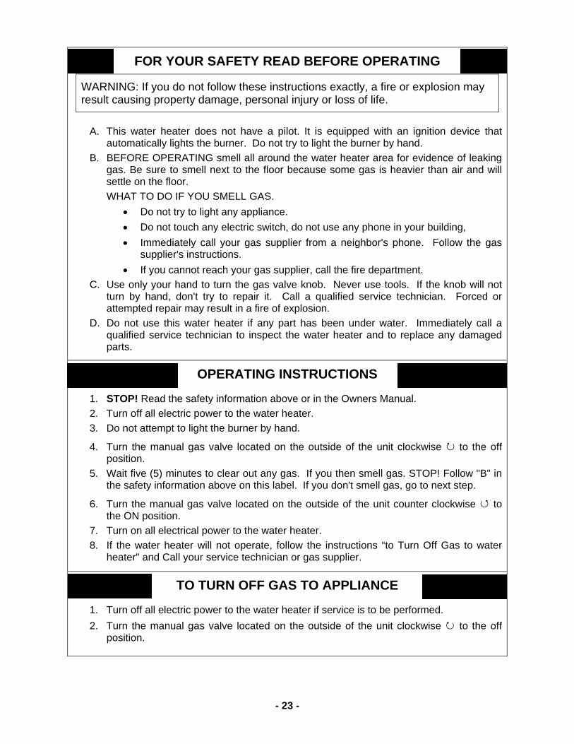
FOR YOUR SAFETY READ BEFORE OPERATING
WARNING: If you do not follow these instructions exactly, a fire or explosion may result causing property damage, personal injury or loss of life.
A. This water heater does not have a pilot. It is equipped with an ignition device that
automatically lights the burner. Do not try to light the burner by hand. B. BEFORE OPERATING smell all around the water heater area for evidence of leaking
gas. Be sure to smell next to the floor because some gas is heavier than air and will settle on the floor. WHAT TO DO IF YOU SMELL GAS.
• Do not try to light any appliance. • Do not touch any electric switch, do not use any phone in your building, • Immediately call your gas supplier from a neighbor's phone. Follow the gas
supplier's instructions. • If you cannot reach your gas supplier, call the fire department.
C. Use only your hand to turn the gas valve knob. Never use tools. If the knob will not turn by hand, don't try to repair it. Call a qualified service technician. Forced or attempted repair may result in a fire of explosion.
D. Do not use this water heater if any part has been under water. Immediately call a qualified service technician to inspect the water heater and to replace any damaged parts.
OPERATING INSTRUCTIONS
1. STOP! Read the safety information above or in the Owners Manual. 2. Turn off all electric power to the water heater. 3. Do not attempt to light the burner by hand.
4. Turn the manual gas valve located on the outside of the unit clockwise ↻ to the off position.
5. Wait five (5) minutes to clear out any gas. If you then smell gas. STOP! Follow "B" in the safety information above on this label. If you don't smell gas, go to next step.
6. Turn the manual gas valve located on the outside of the unit counter clockwise ↺ to the ON position.
7. Turn on all electrical power to the water heater. 8. If the water heater will not operate, follow the instructions “to Turn Off Gas to water
heater" and Call your service technician or gas supplier.
TO TURN OFF GAS TO APPLIANCE
1. Turn off all electric power to the water heater if service is to be performed. 2. Turn the manual gas valve located on the outside of the unit clockwise ↻ to the off
position.

- 24 -
DANGER
Vapors from flammable liquids will explode and catch fire causing death or severe burns. Do not use or store flammable products such as gasoline, solvents or adhesives in the same room or area near the water heater.
Keep flammable products: 1. Far away from heater. 2. In approved containers. 3. Tightly closed 4. Out of children's reach
Vapors: 1. Cannot be seen 2. Vapors are heavier than air 3. Go a long way on the floor 4. Can be carried from other rooms to the
main burner by air currents
WARNING: Do not install water heater where flammable products will be stored.
Read and follow water heater warnings and instructions. If owner’s manual is missing, contact the retailer or manufacturer.
WARNING The outlet hot water temperature of the T-K3-OS water heater is factory set at 122 ºF. Use this heater at your own risk. The set outlet water temperature can cause severe burns instantly or death from scalds. Test the water before bathing or showering. Do not leave children or an infirm person in the bath unsupervised.
DANGER Hot Water temperatures over 125 ºF can cause severe burns instantly or death from scalding. Children, disabled and elderly are at the highest risk of being scalded. Feel water temperature before bathing or showering. Temperature limiting valves are available. Ask professional person.
WARNING: California Proposition 65 lists chemical substances known to the state to cause cancer, birth defects, death, serious illness or other reproductive harm. This product may contain such substances, be their origin from fuel combustion (gas, oil) or components of the product itself.

- 25 -
APPLICATIONS
Space Heating Applications WARNING
• Toxic chemicals used in boiler treatments such as alcohol, glycerol and glycol group must not be introduced into the system when used for open loop potable water and space heating.
• The FLASH T-K3-OS can be used to supply potable water and space heating and shall not be connected to any heating system or component(s) previously used with non-potable water where any chemicals were added to the water heating appliances.
• When the system requires water for space heating at temperatures higher than required for other uses, a means such as a mixing valve shall be installed to temper the water for those other uses in order to reduce scald hazard potential.
• Water temperature over 125 °F can cause severe burns instantly or death from scalds.
• Chemicals such as diluted Glycol can be used for radiant floor, Hydro/fan coil air or Baseboard heating only. The diluted solution of glycol must contain LESS than 30% of Glycol.
Heating application only:
* Size the pump to provide about 2 GPM through the system at 15 Ft of Head plus applications and piping head losses. 2 GPM will allow the system to operate at its optimal performance. . * If the application requires a higher re-circulating flow rate, make sure that the re-circulating flow rate is no greater than 4 GPM. If the flow rate is too high, the system could be damaged by erosion.
This is a concept drawing only.

- 26 -
Dual-Purpose Hot Water Heating (Domestic and Space Heating):
Priority Control Devices such as a flow switch, an Aquastat or other electronic controller can be used to prioritize the domestic water system over the heating system.
Warning: Follow all local codes, or in the absence of local codes, follow the most recent edition of the National Standard Code, ANSI Z21. 10.3.
Warning: This illustration is a concept design only. The reference to the 1/8th hole in check is only for the State of Massachusetts. There are a wide variety of variations to the application of controls and equipment presented. Designers must add all necessary safety and auxiliary equipment to conform to code requirements and design practice. For more details, contact the Takagi Technical Department at (888) 882-5244
* Size the pump to provide at least 2 GPM through the system at 15 Ft of Head plus applications and piping head losses. 2 GPM will allow the system to operate at its optimal performance. * If the application requires a higher re-circulating flow rate, make sure that the re-circulating flow rate is no greater than 4 GPM. If the flow rate is too high, the system could be damaged by erosion.

- 27 -
Recirculation (Aquastat-controlled pump)
* Size the pump to provide at least 2 GPM through the system at 15 Ft of Head plus piping head losses. 2 GPM will allow the system to operate at its optimal performance. * If the application requires a higher re-circulating flow rate, make sure that the re-circulating flow rate is no greater than 4 GPM. If the flow rate is too high, the system could be damaged by erosion.
This is a concept drawing only.

- 28 -
OPTIONAL ITEMS 1. TK-RE02 Temperature Remote Controller
The TK-RE02 Temperature Remote Controller has two functions. It allows the output temperature from the T-K3-OS to be adjusted within the range of 99°F to
167°F, and it also works as a diagnostic tool that will give a concise error code whenever there is a problem with the unit. The temperature options are 99°F, 100°F, 102°F, 104°F, 106°F, 108°F, 110°F, 111°F, 113°F, 115°F, 117°F, 122°F, 131°F, 140°F, 158°F, and 167°F. See the trouble shooting section for information on possible error codes.
2. TK-RB02 Recess box
The TK-RB02 completely houses the T-K3-OS and allows it to be installed recessed into a wall. The recess box measures just over 14” wide, allowing it to easily fit in-between studs.
3. TK-PC01 Pipe cover Designed to be attached directly to the bottom-side of the T-K3-OS, the TK-PC01 will provide a cover for all the pipe connections going into it. Install this pipe cover in accordance with Takagi’s installation instructions and any applicable codes.

- 29 -
COMPONENTS DIAGRAM Case assembly
Computer board assembly
701
708
716
711
405 406 709 712 714
710
718
713
001
002
004
005050
052
052
053
054
707
706
702
- 30 -
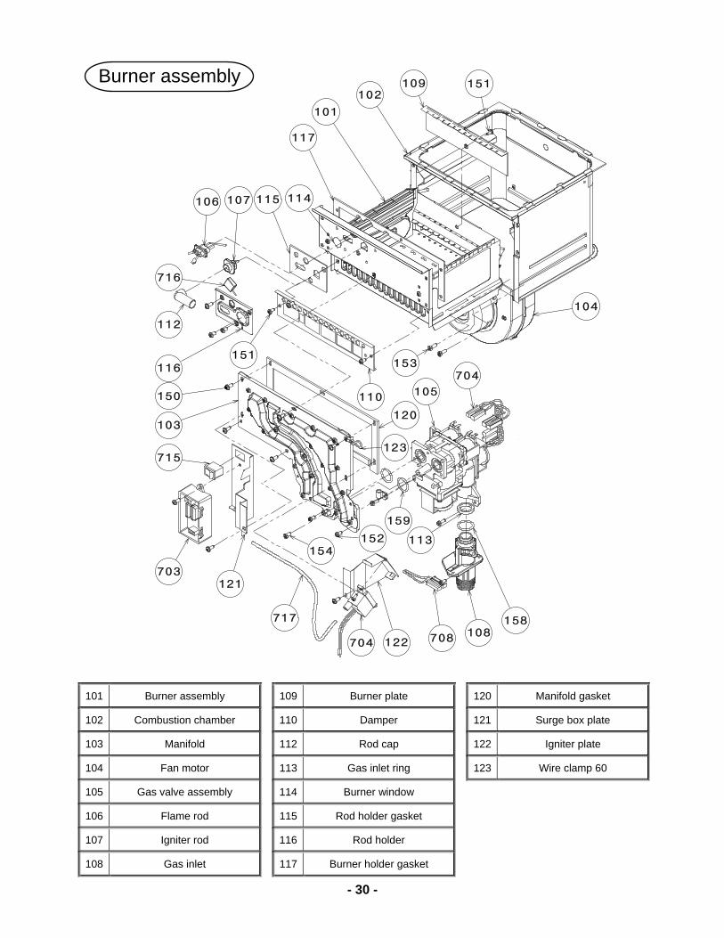
101 Burner assembly 109 Burner plate 120 Manifold gasket
102 Combustion chamber 110 Damper 121 Surge box plate
103 Manifold 112 Rod cap 122 Igniter plate
104 Fan motor 113 Gas inlet ring 123 Wire clamp 60
105 Gas valve assembly 114 Burner window
106 Flame rod 115 Rod holder gasket
107 Igniter rod 116 Rod holder
108 Gas inlet 117 Burner holder gasket
Burner assembly
101
102
103
104
105
106 107
108
109
110
112
113
114115
116
117
120
121
122
123
716
704
708
159
703
715
704
717
151153
151
152154
158
150

- 31 -
401 Heat exchanger assembly 407 Hi-limit switch 414 Inlet drain plug
409 Over heat cut off fuse 415 Inlet water filter 402 Flow adjustment valve
and Flow sensor 410 Heater 416 Inlet heater
403 Water inlet 411 Pipe heater fixing plate 417 Outlet drain plug
404 Water outlet 412 Fuse fixing plate 18 418 Exhaust
405 Outlet thermistor 413 Fuse fixing plate 14 419 Silicon ring
406 Inlet thermistor
Water way assembly
401
402
403
404
405
406
407
409
410
411
412
413
414
415
416
417
418
419
450
456
052
452
457
458
454
454
458
455
456
450
451
453

- 32 -
PARTS LIST Case assembly 001 Case assembly 054 Nylon clamp
002 Front cover 050 Coating screw
washer M4×12
003 Air blockage plate
004 Bracket 051 Coating screw
washer M4×10
005 Junction box 052 Coating screw M4×10
053 Pan screw M4×10
Burner assembly 150 Screw M4×10 155 Pan screw washer M4×10
151 Pan screw M4×8 153 Hex head screw
washer M4×12
152 Pan screw M4×12 154 Hex head screw M4×8
Water way assembly 450 Screw M4×6 454 O-ring P14 EPDM 458 Fastener "14-22"
451 Screw M3×6 455 O-ring P6 EPDM
452 O-ring P16 EPDM 456 O-ring P4 EPDM
453 O-ring P15 EPDM 457 Fastener "16A"
Computer board assembly 701 Computer board 709 Flow sensor wire
702 Transformer TD-227 715 AC120V power ON-OFF
switch
703 Surge box 710 Flame rod wire
716 Igniter and Freeze protection wire
704 Igniter 711 Gas valve wire 717 High voltage ignite cable
705 Freeze protection thermostat 712 Flow adjustment valve wire 718 AC120V wire
706 Fuse 713 Fan motor cable
707 Fuse box
708 Computer board cover 714 Proportional gas valve wire

- 33 -
Out Put Temperature vs. GPM (Max. 7.0 GPM) with Various Ground Water TemperatureAssuming Correct Gas pipe size
0.0
1.0
2.0
3.0
4.0
5.0
6.0
7.0
8.0
Out put Hot Water Temperature
Out
Put
Hot
Wat
er G
PM
40 F 50 F 60 F 70 F
40 F 6.2 5.7 5.2 4.8 4.4 4.1 3.9 3.7 3.5 3.3 3.1 2.8 2.6 2.5 2.4 2.3 2.2
50 F 7.0 6.9 6.2 5.7 5.2 4.8 4.4 4.1 3.9 3.7 3.5 3.1 2.8 2.7 2.6 2.5 2.4
60 F 7.0 6.9 6.2 5.7 5.2 4.8 4.4 4.1 3.9 3.5 3.1 3.0 2.8 2.7 2.6
70 F 7.0 6.9 6.2 5.9 5.4 5.0 4.7 4.1 3.6 3.4 3.3 3.1 3.0
90 95 100 105 110 115 120 125 130 135 140 150 160 165 170 175 180
Output H
ot Water G
PM

- 34 -
WARRANTY Takagi units must be installed by licensed professionals; installation done by anyone other than licensed professionals will result in the Nullification of the Takagi warranty. To be protected by the warranty, the enclosed warranty card must be completed and returned within 45 days of original purchasing date by retailed buyer. Proof of copy of original purchasing date must be sent in with the warranty card. Failure to return the warranty card in due time will void any warranty claims. Based on the condition herein, the customer may register online with attached proof of original purchasing date via the Internet (www.takagi.com/warranty). General terms of limited warranty: The manufacturer, Takagi Industrial Co. USA, Inc. will honor our warranty to the original retailed buyer only, and it is not transferable. This warranty strictly covers failed mechanical and electrical parts due to factory defects in normal usage and within the applicable period specified below excluding field labor expenses for service, repairs, reinstallation, permits, or removal and disposal of the failed water heater, or defective component parts and shipping. Takagi is not liable for any special, incidental, or indirect consequential damages including property or personal damages, loss of use, failure to install drain pan under unit, or inconvenience. Parts Warranty: If a mechanical and/or electrical part except the heat-exchanger fails within five (5) years in normal residential and three (3) years in commercial with proper installation (see instruction from installation manual) from the purchasing date, Takagi Industrial Co. USA Inc. will furnish a replacement part(s) excluding field labor and shipping. Heat-Exchanger Warranty: If the heat-exchanger fails within ten (10) years in normal residential operation with proper installation (see instruction from installation manual) from the installation date, Takagi Industrial Co. USA Inc. will furnish a brand new heat-exchanger or a refurbished or conditioned tank-less water heater with same model. For commercial, industrial or/ and recirculation applications or/ and more than a single family residential dwelling, the heat-exchanger is covered within three (3) years of usage excluding labor and shipping. This warranty will not cover the followings:
1. Any Takagi unit that is not installed by a licensed plumber, gas installer, or contractor. 2. Defects or malfunctions due to improper installation, abnormal application, and lack of
maintenance. 3. Damage due to abuse, accident, fire, flood, freezing, or any act of GOD. 4. Failure of Takagi unit due to the water heater being operated in a corrosive, chemically
contaminated, lint, fiber glass, or any similar environment. 5. Failure of Takagi unit due to abnormal hardness water quality (scale build up), incorrect water
pressure, untreated well water, high (excessive) supplied gas pressure from Uniform Plumbing Code specifications.
6. Failure due to excessive temperature that is higher than the factory calibrated temperature limits. 7. Failure or damage due to unauthorized alterations, attachments, repair and/or improperly
converted gas type as specified on the rating plate. 8. Damage due to freezing environment without proper preventive measure as instructed in the
installation manual. 9. Damage from condensation due to extensive vent length without condensation drip and/or not
following the installation manual. 10. Damage from not installed in accordance with applicable local, state codes, ordinances and good
trade practices. 11. Unit is installed outside the United States of America and Canada excluding U.S. territories.