Embed Size (px)
Citation preview

Telecommunication Transmission Systems for Signalling and Control Systems
T HR SC 01256 ST
Standard
Version 2.0
Issued date: 29 September 2017
© State of NSW through Transport for NSW 2017

T HR SC 01256 ST Telecommunication Transmission Systems for Signalling and Control Systems
Version 2.0 Issued date: 29 September 2017
Important message
This document is one of a set of standards developed solely and specifically for use on Transport Assets (as defined in the Asset Standards Authority Charter). It is not suitable for any other purpose. The copyright and any other intellectual property in this document will at all times remain the property of the State of New South Wales (Transport for NSW). You must not use or adapt this document or rely upon it in any way unless you are providing products or services to a NSW Government agency and that agency has expressly authorised you in writing to do so. If this document forms part of a contract with, or is a condition of approval by a NSW Government agency, use of the document is subject to the terms of the contract or approval. To be clear, the content of this document is not licensed under any Creative Commons Licence. This document may contain third party material. The inclusion of third party material is for illustrative purposes only and does not represent an endorsement by NSW Government of any third party product or service. If you use this document or rely upon it without authorisation under these terms, the State of New South Wales (including Transport for NSW) and its personnel does not accept any liability to you or any other person for any loss, damage, costs and expenses that you or anyone else may suffer or incur from your use and reliance on the content contained in this document. Users should exercise their own skill and care in the use of the document. This document may not be current and is uncontrolled when printed or downloaded. Standards may be accessed from the Asset Standards Authority website at www.asa.transport.nsw.gov.au
© State of NSW through Transport for NSW 2017

T HR SC 01256 ST Telecommunication Transmission Systems for Signalling and Control Systems
Version 2.0 Issued date: 29 September 2017
Standard governance
Owner: Lead Signals and Control Systems Engineer, Asset Standards Authority
Authoriser: Chief Engineer, Asset Standards Authority
Approver: Executive Director, Asset Standards Authority on behalf of the ASA Configuration Control Board
Document history
Version Summary of changes
1.0 First issue
2.0 Second issue clarifies requirements in Section 8, Section 9, Section 10 and Section 11
For queries regarding this document, please email the ASA at [email protected] or visit www.asa.transport.nsw.gov.au
© State of NSW through Transport for NSW 2017

T HR SC 01256 ST Telecommunication Transmission Systems for Signalling and Control Systems
Version 2.0 Issued date: 29 September 2017
Preface The Asset Standards Authority (ASA) is a key strategic branch of Transport for NSW (TfNSW).
As the network design and standards authority for NSW Transport Assets, as specified in the
ASA Charter, the ASA identifies, selects, develops, publishes, maintains and controls a suite of
requirements documents on behalf of TfNSW, the asset owner.
The ASA deploys TfNSW requirements for asset and safety assurance by creating and
managing TfNSW's governance models, documents and processes. To achieve this, the ASA
focuses on four primary tasks:
• publishing and managing TfNSW's process and requirements documents including TfNSW
plans, standards, manuals and guides
• deploying TfNSW's Authorised Engineering Organisation (AEO) framework
• continuously improving TfNSW’s Asset Management Framework
• collaborating with the Transport cluster and industry through open engagement
The AEO framework authorises engineering organisations to supply and provide asset related
products and services to TfNSW. It works to assure the safety, quality and fitness for purpose of
those products and services over the asset's whole-of-life. AEOs are expected to demonstrate
how they have applied the requirements of ASA documents, including TfNSW plans, standards
and guides, when delivering assets and related services for TfNSW.
Compliance with ASA requirements by itself is not sufficient to ensure satisfactory outcomes for
NSW Transport Assets. The ASA expects that professional judgement be used by competent
personnel when using ASA requirements to produce those outcomes.
About this document
This standard establishes the minimum requirements for the provision of transmission systems
used only by signalling and control systems for heavy rail. This standard may be used by a
number of different engineering disciplines, such as signalling, safety, systems,
telecommunication and control systems.
Version 1.0 (issue date 13 October 2016) of this document superseded SPG 1256
Communication Links for Signalling Control, version 1.1.
This document is a second issue. The changes in version 2.0 clarify requirements in Section 8,
Section 9, Section 10 and Section 11.
© State of NSW through Transport for NSW 2017 Page 4 of 46

T HR SC 01256 ST Telecommunication Transmission Systems for Signalling and Control Systems
Version 2.0 Issued date: 29 September 2017
Foreword
This document details generic requirements (based on the referenced international standards
and guidelines), which can be implemented using a multitude of industry approved techniques.
In order to explain requirements clearly, generic reference architecture is explained in the
document. Background information, guidance and examples are provided in the appendices of
this document to assist the reader in understanding TfNSW specific issues.
The requirements for reliability, availability, maintainability, safety (RAMS) and security provided
in this standard have been drawn from a range of international standards and guidelines.
Specifically, the RAMS requirements are based on IEC 62278 Railway applications –
Specification and demonstration of reliability, availability, maintainability and safety (RAMS); the
safety requirements are based on IEC 62280 Railway applications – Communication, signalling
and processing systems – Safety related communication in transmission systems and the
security requirements are based on ISO/IEC 27033 Information technology - Security
techniques - Network Security and NIST 800 82 Guide to Industrial Control Systems Security.
© State of NSW through Transport for NSW 2017 Page 5 of 46

T HR SC 01256 ST Telecommunication Transmission Systems for Signalling and Control Systems
Version 2.0 Issued date: 29 September 2017
Table of contents 1. Introduction .............................................................................................................................................. 7
2. Purpose .................................................................................................................................................... 7 2.1. Scope ..................................................................................................................................................... 7 2.2. Application ............................................................................................................................................. 9
3. Reference documents ............................................................................................................................. 9
4. Terms and definitions ........................................................................................................................... 11
5. Signalling and control system generic architecture .......................................................................... 12
6. Failure requirements ............................................................................................................................. 14
7. Delay requirements ............................................................................................................................... 15
8. Availability requirements ...................................................................................................................... 16
9. Reliability requirements ........................................................................................................................ 16
10. Maintainability requirements ................................................................................................................ 17
11. Diversity and redundancy requirements ............................................................................................. 18
12. Safety requirements .............................................................................................................................. 19
13. Security requirements ........................................................................................................................... 19
14. Telecommunication cables requirements ........................................................................................... 21
15. Configuration management requirements .......................................................................................... 21
Appendix A Supporting information ..................................................................................................... 22 A.1. Failure .................................................................................................................................................. 22 A.2. Transmission delays ............................................................................................................................ 23 A.3. Reliability, availability, maintainability and safety (RAMS) .................................................................. 23 A.4. Diversity and redundancy .................................................................................................................... 25 A.5. Cyber security ...................................................................................................................................... 28
Appendix B Signalling and control systems communication paths in TfNSW ................................ 31
Appendix C General characteristics and categorisation of transmission systems ........................ 40 C.1. Dedicated physical links ...................................................................................................................... 40 C.2. Circuit switched networks .................................................................................................................... 41 C.3. Packet switched networks ................................................................................................................... 42 C.4. Wireless ............................................................................................................................................... 43
Appendix D Threats and defences analysis example ......................................................................... 45
Appendix E Communication path presentation example ................................................................... 46
© State of NSW through Transport for NSW 2017 Page 6 of 46
T HR SC 01256 ST Telecommunication Transmission Systems for Signalling and Control Systems
Version 2.0 Issued date: 29 September 2017
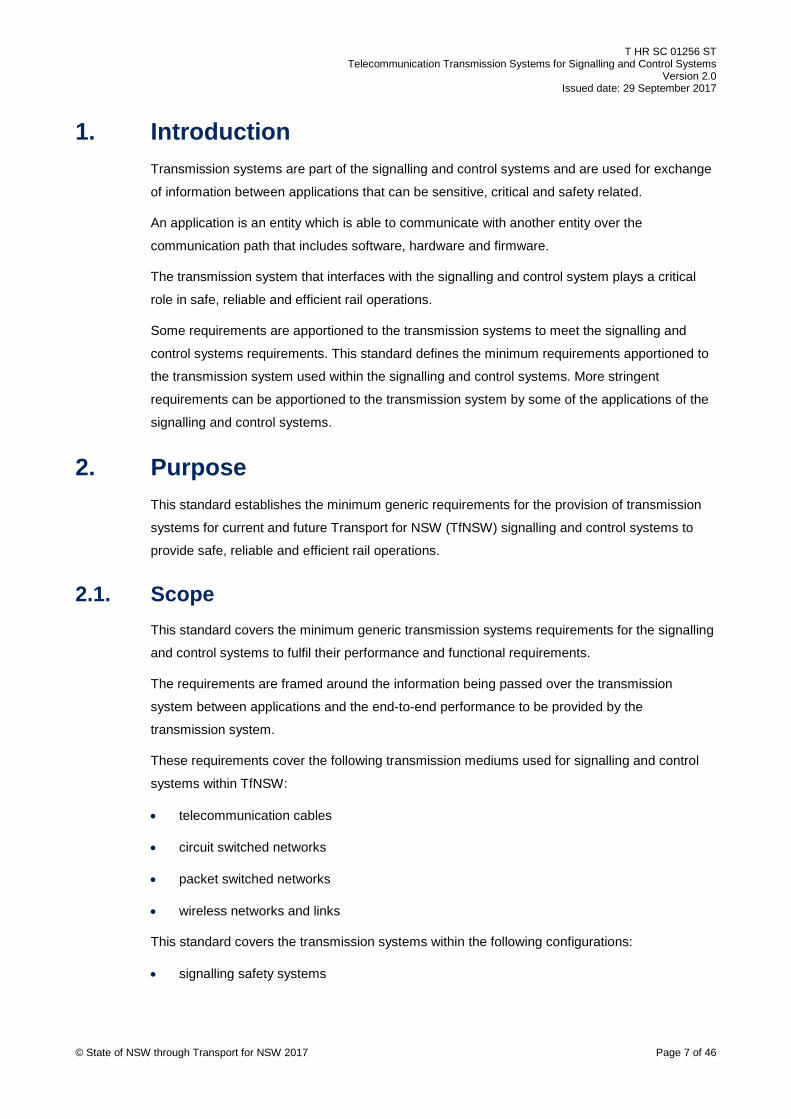
1. Introduction Transmission systems are part of the signalling and control systems and are used for exchange
of information between applications that can be sensitive, critical and safety related.
An application is an entity which is able to communicate with another entity over the
communication path that includes software, hardware and firmware.
The transmission system that interfaces with the signalling and control system plays a critical
role in safe, reliable and efficient rail operations.
Some requirements are apportioned to the transmission systems to meet the signalling and
control systems requirements. This standard defines the minimum requirements apportioned to
the transmission system used within the signalling and control systems. More stringent
requirements can be apportioned to the transmission system by some of the applications of the
signalling and control systems.
2. Purpose This standard establishes the minimum generic requirements for the provision of transmission
systems for current and future Transport for NSW (TfNSW) signalling and control systems to
provide safe, reliable and efficient rail operations.
2.1. Scope This standard covers the minimum generic transmission systems requirements for the signalling
and control systems to fulfil their performance and functional requirements.
The requirements are framed around the information being passed over the transmission
system between applications and the end-to-end performance to be provided by the
transmission system.
These requirements cover the following transmission mediums used for signalling and control
systems within TfNSW:
• telecommunication cables
• circuit switched networks
• packet switched networks
• wireless networks and links
This standard covers the transmission systems within the following configurations:
• signalling safety systems
© State of NSW through Transport for NSW 2017 Page 7 of 46

T HR SC 01256 ST Telecommunication Transmission Systems for Signalling and Control Systems
Version 2.0 Issued date: 29 September 2017
• between the signalling safety system and other systems such as traffic management
systems and condition monitoring
• internally within the traffic management system's components, such as servers,
workstations, loggers
• interface between the traffic management systems
• interface between the traffic management systems and other systems such as timetable
servers, monitoring systems, web publishing systems and external loggers
• remote components or systems accessing the signalling and control systems
• onboard installations on heavy rail rolling stock assets owned by TfNSW
All protocol related requirements within this standard set the requirements at the open systems
interconnection (OSI) data link layer and above as detailed in ISO/IEC 7498-1 Information
Technology – Open Systems Interconnection – Basic Reference Model: The Basic Model –
Part 1. The OSI physical layer details the electrical, mechanical and procedural interface to the
transmission medium.
This standard covers the controls and configuration of the physical medium, such as cables and
network elements, in relation to their security, transmission system categorisation and
availability.
This standard does not cover requirements for the components of the transmission subsystems
as the performance of the signalling and control systems is based on the end to end
performance of the transmission system used between applications.
Requirements for transmission subsystems and their components are detailed in
T MU TE 41001 ST Packet Switched Networks – Wired Networks and T MU TE 41004 ST
Packet Switched Networks – Wireless Local Area Networks.
Any conflict that exists between this standard and other standards will be resolved by the ASA.
This standard does not require additional safety integrity level (SIL) activities to those described
in IEC 62280 Railway applications - Communication, signalling and processing systems –
Safety related communication in transmission systems and IEC 62425 Railway applications –
Communication, signalling and processing systems – Safety related electronic systems for
signalling.
T MU MD 00005 GU Type Approval of Products is applicable to equipment or products used
within the transmission systems utilised by the signalling and control systems' applications.
© State of NSW through Transport for NSW 2017 Page 8 of 46

T HR SC 01256 ST Telecommunication Transmission Systems for Signalling and Control Systems
Version 2.0 Issued date: 29 September 2017
2.2. Application This standard applies to all parties involved in the provision of new transmission systems for
both new and existing sites in the metropolitan rail area for the whole asset life cycle of the
signalling and control system.
If the transmission system is used for multiple purposes, then this standard applies only to parts
of the transmission system that are used by signalling and control systems information transfer
as long as the independence of the signalling and control system information can be
demonstrated so far as is reasonably practicable (SFAIRP).
This standard is applicable to transmission systems used within subsystems or systems that are
part of another system.
This standard applies to the modification of existing installations. It does not apply to projects
that are currently in progress or any approved projects that are implemented at new sites.
This standard applies if the transmission system is used for the maintenance and monitoring of
the signalling and control systems and its components, including the transmission systems.
This standard can be used by other disciplines such as signalling, safety and control systems to
determine the apportioned transmission system requirements based on the signalling and
control system requirements.
If the signalling and control system does not specify the transmission system requirements for
its design requirements, then the transmission system requirements detailed in this standard will
be applicable as default requirements.
3. Reference documents The following documents are cited in the text. For dated references, only the cited edition
applies. For undated references, the latest edition of the referenced document applies.
International standards
IEC 62278 Railway applications - Specification and demonstration of reliability, availability,
maintainability and safety (RAMS)
IEC 62279 Railway applications – Communication, signalling and processing systems –
Software for railway control and protection systems
IEC 62280 Railway applications - Communication, signalling and processing systems – Safety
related communication in transmission systems
IEC 62425 Railway applications – Communication, signalling and processing systems – Safety
related electronic systems for signalling
IEC 62443 (all parts) – Industrial communications networks – Network and system security
© State of NSW through Transport for NSW 2017 Page 9 of 46

T HR SC 01256 ST Telecommunication Transmission Systems for Signalling and Control Systems
Version 2.0 Issued date: 29 September 2017
ISO/IEC 7498-1 Information Technology – Open Systems Interconnection – Basic Reference
Model: The Basic Model
ISO/IEC 27033 (series) Information technology - Security techniques - Network security
Australian standards
AS/NZS ISO/IEC 18028 (series) Information technology – Security techniques – IT network
security
AS ISO/IEC 27001 Information technology – Security techniques – Information security
management systems – Requirements
AS ISO/IEC 27002 Information technology – Security techniques – Code of practice for
information security controls
Transport for NSW standards
T HR TE 01001 ST Communication Outdoor Cabling
T HR TE 01002 ST Signalling Bungalow Communications Cabling
T MU MD 00005 GU Type Approval of Products
T MU MD 20001 ST System Safety Standard for New or Altered Assets
T MU TE 41001 ST Packet Switched Networks – Wired Networks
T MU TE 41004 ST Packet Switched Networks – Wireless Local Area Networks
TMM P001 Copper Cable Termination
TMM P021 Optical Fibre Cable Joining, Termination and Management
Other reference documents
Australian Government 2016, Australia's Cyber Security Strategy
International Electrotechnical Committee 2004, Reliability data handbook – Universal model for
reliability prediction of electronics components, PCBs and equipment – IEC/TR 62380 Ed 1.0
(Bilingual 2004)
International Union of Railways (UIC) 2013, IP Introduction to Railways - Guideline for the fixed
telecommunication network version 2.0
National Institute of Standards and Technology (NIST) 2015, Guide to Industrial Control
Systems (ICS) Security – NIST Special Publication 800-82 Revision 2
National Institute of Standards and Technology (NIST) 2008, Guide to SSL VPNs – NIST
Special Publication 800-113
National Institute of Standards and Technology (NIST) 2014, Framework for Improving Critical
Infrastructure Cybersecurity
© State of NSW through Transport for NSW 2017 Page 10 of 46

T HR SC 01256 ST Telecommunication Transmission Systems for Signalling and Control Systems
Version 2.0 Issued date: 29 September 2017
4. Terms and definitions The following terms and definitions apply in this document:
AEO Authorised Engineering Organisation
apportionment process whereby the RAMS elements for a system are subdivided between the
various items which comprise the system to provide individual targets (IEC 62278:2002)
ASA Asset Standards Authority
closed transmission system fixed number or fixed maximum number of participants linked by
a transmission system with well-known and fixed properties, and where risk of unauthorised
access is considered negligible (EN 50159:2010)
common cause failure a failure which is the result of one or more events which causes a
coincidence of failure states of two or more components leading to a system failing to perform
its required function
IP internet protocol
link a physical connection between two participants for the purpose of transmitting and
receiving information
metropolitan rail area The rail freight network and the rail passenger network within the
metropolitan rail area bounded by Newcastle (in the north), Richmond (in the northwest),
Bowenfels (in the west), Macarthur (in the southwest) and Bomaderry (in the south), and all
connection lines and sidings within these areas, but excluding private sidings
MTBF mean time between failures
MTTF mean time to failure
open transmission system transmission system with an unknown number of participants,
having unknown variable and non-trusted properties, used for unknown telecommunication
services and having the potential for unauthorised access (EN 50159:2010)
OSI open systems interconnection
RAMS reliability, availability, maintainability and safety
RBD reliability block diagram
safety case documented demonstration that the product complies with the specified safety
requirements (EN 50159:2010)
safety related carries responsibility for safety
SFAIRP so far as is reasonably practicable
© State of NSW through Transport for NSW 2017 Page 11 of 46

T HR SC 01256 ST Telecommunication Transmission Systems for Signalling and Control Systems
Version 2.0 Issued date: 29 September 2017
SIL safety integrity level; number which indicates the required degree of confidence that a
system will meet its specified safety functions with respect to systematic failures
(EN 50159:2010)
TfNSW Transport for New South Wales
threat potential violation of safety (EN 50159:2010)
transmission system service used by the application to communicate message streams
between a number of participants, who may be sources or sinks of information (EN 50159:2010)
5. Signalling and control system generic architecture The signalling and control system that is referred in this standard is based on the generic
distributed system architecture as shown in Figure 1.
Note: For simplicity, Figure 1 does not show components and interfaces that are not
relevant to this standard.
The signalling and control system can contain a number of components, which can be a product
or another system. For example, a system can contain interlocking, radio block centre (RBC)
and traffic management systems. The overall system requirements are distributed system
components according to their allocated functionalities and capabilities. These requirements are
specified in standards or system specifications. Each product, system or system component in
turn defines its constraints and assumptions in order to fulfil its allocated requirements.
When information exchange takes place between applications within a system using a
transmission system, then the transmission systems become a part of the system. In most
cases, communicated information can have sensitive, critical and safety critical characteristics,
such as railway signalling. Therefore transmission systems play a critical role for safe and
reliable rail operations.
The interface components shown in Figure 1 form part of the system components and provide
the interface between applications and the transmission system for each system component; for
example, a serial card or network card or universal serial bus (USB) to interface serial link or
network or signalling data link.
© State of NSW through Transport for NSW 2017 Page 12 of 46

T HR SC 01256 ST Telecommunication Transmission Systems for Signalling and Control Systems
Version 2.0 Issued date: 29 September 2017
Application nA Application mBApplication mAApplication nB
Application nC
Interface Component n2Interface Component n1 Interface Component m1 Interface Component m2
TRANSMISSION SYSTEMS
….
System Component nWith
Safety Case n
System Component mWith
Safety Case m
Transmission Systems:- Any type of cable, including optical cable- Packet Switching Network- Circuit Switched network- Radio or WiFi
Note: Each System Component may have its own local Transmission Systems. Not drawn in order to keep the figure less complicated.
System Components:- Server- Network equipment- PC or laptop or tablet or mobile device- Supporting equipment, such as KVMA, convertors- RBC, IXL, Object Controllers- IO Systems
Interface Components- Serial Interface- Parallel Interface- Network Interface- USB
Application:- Software- Firmware- Executive- Ladder Logic- Hardware
Communication Path between applications
© State of NSW through Transport for NSW 2017 Page 13 of 46
Figure 1 – Distributed signalling and control system's generic reference architecture
T MU MD 20001 ST System Safety Standard for New or Altered Assets and the following
international standards provide the safety management framework that is usually applied to
products and systems:
• IEC 62278 Railway applications - Specification and demonstration of reliability, availability,
maintainability and safety (RAMS)
• IEC 62279 Railway applications – Communication, signalling and processing systems –
Software for railway control and protection systems
• IEC 62280 Railway applications - Communication, signalling and processing systems –
Safety related communication in transmission systems
• IEC 62425 Railway applications – Communication, signalling and processing systems –
Safety related electronic systems for signalling
Based on the safety management framework, exported hazards, safety related application
constraints and assumptions associated with the products and systems can have residual
hazards that cannot be managed as part of the product or system. These hazards related to or
able to be controlled through the transmission system should be managed SFAIRP as part of
the integration of a safety related product or system within the transmission system.
Therefore, a number of requirements are allocated to the transmission systems, which are
derived from system components, such as constraints, assumptions and residual hazards. Due
T HR SC 01256 ST Telecommunication Transmission Systems for Signalling and Control Systems
Version 2.0 Issued date: 29 September 2017
to the nature of delivering a safe and reliable system, some requirements are defined as
processes, arguments and their outcomes.
The following examples show the allocation of performance requirement:
i. If the overall availability of the system is specified as 99.99% and the system component
has an allocated availability of 99.995% as a result of apportioning process, then the
system component can fulfil its availability requirement if the availability of the transmission
system component is 99.999%.
ii. As a result of the safety case outcome, the interlocking system can communicate with
another system over a category 2 transmission system due to its protocol characteristics in
order to fulfil its safety requirements.
The requirements of this standard takes into account the heterogeneity of transmission systems
and allows for the use of different types of transmission mediums and equipment to be used
between signalling and control systems' applications.
The transmission system requirements are for the complete communications path between
signalling and control system applications as shown in Figure 1, including equipment and
transmission mediums.
All transmission systems within the signalling and control system should be part of the system
safety assessment. Different parts of the transmission systems can be assessed in various
system components' safety assessment. For example, transmission systems used by an
interlocking can be part of the interlocking's safety assessment. If that transmission system is
not used by any other system, then the transmission system need not be assessed.
If the transmission system is used in more than one application, then the interactions and
effects on other applications should be considered and analysed, including hazards and impact
on performance requirements as detailed in this standard.
Context and background information for requirements are provided in Appendix A.
Generic requirements for transmission systems are based on the information provided in
Appendix B.
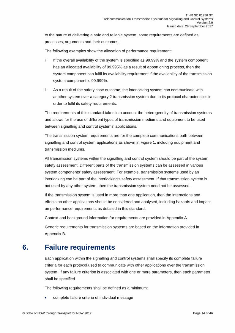
6. Failure requirements Each application within the signalling and control systems shall specify its complete failure
criteria for each protocol used to communicate with other applications over the transmission
system. If any failure criterion is associated with one or more parameters, then each parameter
shall be specified.
The following requirements shall be defined as a minimum:
• complete failure criteria of individual message
© State of NSW through Transport for NSW 2017 Page 14 of 46

T HR SC 01256 ST Telecommunication Transmission Systems for Signalling and Control Systems
Version 2.0 Issued date: 29 September 2017
• retry criteria
• timeliness criteria
• message ordering criteria
The failure criteria of the overall transmission system shall be the most stringent failure criteria if
different types of messages are used within the same transmission system.
Planned activities, which contain assessed and approved controls in place for safe and reliable
signalling and train operations cannot be assumed as a failure.
Random failures within the transmission systems shall be analysed for impact or contribution to
the failure of the signalling and control system.
The AEOs' processes and procedures should mitigate the systematic failures within the
transmission system using industry acceptable engineering techniques such as those
mentioned in IEC 62278.
7. Delay requirements Transmission delays determine the responsiveness and timeliness of the information passed
between one signalling and control system application to another. These attributes are detailed
as part of the communication protocols and are apportioned to the transmission systems as
transmission delay requirements.
Transmission system delay requirements shall be specified by the signalling and control system
application using the following generic parameters:
• delays in milliseconds
• number of retries initiated by the application
If the protocol used between applications requires other delay requirements or parameters, then
they shall be specified to set the requirements on the transmission systems.
Communication path is the complete path, which transfers message streams between two
applications, including transmission mediums, equipment, technologies, interfaces and any
other items, which contribute to communication.
The default transmission system delay from one application to another application over the
complete communication path shall be less than 100 ms (95% of the distribution of all delays),
excluding the application's processing time.
The transmission system delays can be caused by all transmission mediums, equipment, and
utilisation of diversity configurations between two system components, which are used by
applications as shown in Figure 1.
© State of NSW through Transport for NSW 2017 Page 15 of 46

T HR SC 01256 ST Telecommunication Transmission Systems for Signalling and Control Systems
Version 2.0 Issued date: 29 September 2017
The transmission system delay requirements should take into account, but are not limited to the
following: the communication path's characteristics, switching to diverse communication path,
encryption/decryption, message overheads of the transmission system, processing, routing,
checking, retries, jitters, latency.
8. Availability requirements The availability of signalling and control systems is based on the operational impacts such as
delays, disruptions and operational procedures that have lower level of safety.
The signalling and control systems have three levels of availability requirements in the
communication path between two signalling and control systems. These levels are based on
their allocated criticality and safety requirements for a function.
The following are the three levels of requirements:
i. Safety related functions - used in the safety applications and signalling data. The
performance of the safety related functions shall not be less than 99.999%.
ii. High availability functions - used in the operationally critical applications that do not have
safety implications, such as indication and controls within the traffic management system.
The performance of high availability functions shall not be less than 99.995%.
iii. Standard functions - used in all other applications, such as logging. The performance of
standard functions shall not be less than 99.99%.
In the absence of signalling and control systems apportioned requirements, the default
availability requirement of the transmission system shall be 'safety related function'. The
availability requirements shall be demonstrated by evidence based on industry accepted
techniques such as reliability block diagram (RBD). The evidence based analysis shall also
cover common cause failures, redundancy and so on. The evidence shall be provided in order
to manage the systematic failures within the transmission systems.
9. Reliability requirements The reliability of the signalling and control system depends on the transmission system used in
the communication path between one signalling and control system application and another.
Reliability requirements are applicable for each communication path and non-redundant
configuration to support the confidence level of the operational availability requirement.
The signalling and control systems have three levels of reliability requirements for each
complete communication path between two signalling and control systems. These levels are
based on their allocated criticality and safety requirements for a function.
© State of NSW through Transport for NSW 2017 Page 16 of 46

T HR SC 01256 ST Telecommunication Transmission Systems for Signalling and Control Systems
Version 2.0 Issued date: 29 September 2017
The following are the three levels of reliability requirements:
i. For the safety related functions, the mean time between failures (MTBF) or the mean time
to failure (MTTF) shall not be less than 100,000 hours.
ii. For high availability functions, the MTBF or MTTF shall not be less than 70,000 hours.
iii. For standard functions, the MTBF or MTTF shall not be less than 50,000 hours.
In the absence of signalling and control systems apportioned requirements, the default reliability
requirement of the transmission system shall be 'safety related function'. Reliability calculations
shall be based on industry accepted techniques such as RBD or the prediction data which is
based on IEC/TR 62380.
Information can be extracted from existing site applications and if the amount of information is
statistically justifiable, then the empirical reliability information shall be used for the reliability
calculations.
The possibility of having multiple or secondary failures due to failure and repair delays within the
transmission system shall be considered.
10. Maintainability requirements Maintainability is determined by the extent to which a failed component or system is restored or
repaired to the specified condition within the specific period of time when maintenance is
performed in accordance with prescribed procedures.
Maintainability requirements are applicable for each communication path and non-redundant
configuration.
The maintainability parameters shall support the reliability and availability requirements set for
the transmission system in accordance with Section 8 and Section 9 of this document.
The signalling and control systems have three different levels of downtime requirements
according to their allocated criticality and safety requirements for a function.
The following are the three levels of down time requirements:
i. For safety related functions, the mean time to restore the transmission system shall not
exceed 1 h on average for each complete communication path.
ii. For high availability functions, the mean time to restore the transmission system shall not
exceed 3.5 h on average for each complete communication path.
iii. For standard functions, the mean time to restore the transmission system shall not exceed
5 h on average for each complete communication path.
In the absence of signalling and control systems apportioned requirements, the default
maintainability requirement of the transmission system shall be 'safety related function'.
© State of NSW through Transport for NSW 2017 Page 17 of 46

T HR SC 01256 ST Telecommunication Transmission Systems for Signalling and Control Systems
Version 2.0 Issued date: 29 September 2017
The following parameters shall be set for the transmission system so that the availability and
reliability requirements are fulfilled:
• mean time between maintenance, both corrective and preventative
• mean time to maintain, both corrective and preventative
11. Diversity and redundancy requirements The transmission system shall provide the required diversity and redundancy as apportioned
and defined by the requirements for the signalling and control systems applications. In the
absence of such requirements, the default diversity and redundancy shall be 'route diversity' for
the telecommunication cables and 'full diversity' for the switched network and packeted network
as detailed in Appendix A.4.
The transmission system design shall be supported by evidence based risk analysis and
industry standard methodologies such as RBD in order to prove that all requirements are
fulfilled. The common cause failure analysis shall also be a part of the analysis in order to
identify such failure conditions and shall be incorporated into the RAM requirement analysis of
the transmission system.
If the transmission system's diversity and redundancy requirements cannot be met, then an
evidence based analysis shall be conducted stating the reasons for deviation from the
requirements and impact on the availability requirement.
The default convergence or changeover, which can cause a failure as detailed in Section 6 shall
be less than or equal to 150 ms (95% of the distribution of all convergence or changeover time).
The convergence or changeover times for the complete communication paths shall be less than
75% of the maximum disruption time that the application can tolerate, including protocol specific
retries configuration. If the convergence or changeover time of the complete communication
path is greater than the tolerable maximum disruption time, then its impact and mitigation shall
be analysed with supporting evidences.
If the communication path between two applications contains different types of transmission
mediums or technologies, then each transmission medium or technology shall be analysed
individually in order to determine the diversity characteristics of the complete communication
path within the transmission system. The overall diversity or redundancy of the transmission
system shall be equal to the lowest level of diversity and redundancy of the components of the
transmission system.
For dedicated communication paths, such as telecommunication cables or circuit switched
networks, the design shall consider the following:
i. one of the redundant paths shall be as direct as possible, that is, the path shall traverse the
shortest path length
© State of NSW through Transport for NSW 2017 Page 18 of 46

T HR SC 01256 ST Telecommunication Transmission Systems for Signalling and Control Systems
Version 2.0 Issued date: 29 September 2017
ii. at least one complete path shall use TfNSW infrastructure
iii. the path shall be a dedicated path installed independently for the purpose
iv. the path shall pass through the minimum number of equipment
v. the path configuration shall be the simplest that can be achieved
The level of compliance and the reason for variation, if any, for each communication path shall
be documented.
12. Safety requirements All communication paths used between signalling and control system application within the
transmission system shall be categorised as detailed in IEC 62280. This categorisation shall be
specific to the proposed configuration and its components. The categorisation shall be
demonstrated by a safety case based on IEC 62425. The assessment shall be kept up-to-date
during the complete life cycle of the transmission system.
If the safety case does not exist or the safety case does not satisfy the requirements of
IEC 62425, then the transmission system shall be classified as 'category 3 and open
transmission system'.
The specified transmission system category shall be applicable to the complete communication
path as shown in Figure 1 including a redundant communication path.
If multiple communication paths with different transmission systems requirements use the same
transmission system, then the most stringent transmission system requirements shall be
implemented.
13. Security requirements The transmission systems used within the signalling and control systems shall provide security
against emerging, known and potential IT threats, irrespective of its safety functions.
The signalling and control systems shall be assumed as industrial automation and control
systems as detailed in IEC/TS 62443-1-1 Industrial communication networks – Network and
system security – Part 1-1: Terminology, concepts and models. All requirements, technologies
and techniques detailed within IEC 62443 that are applicable to transmission systems shall be
considered and supported with evidences.
The security measures within the transmission system shall not impact the ability of the
signalling and control system to meet its performance requirements, particularly, the
transmission delays.
Some industry accepted security measures are detailed in Appendix A.5.1, Appendix A.5.2 and
Appendix A.5.3.
© State of NSW through Transport for NSW 2017 Page 19 of 46

T HR SC 01256 ST Telecommunication Transmission Systems for Signalling and Control Systems
Version 2.0 Issued date: 29 September 2017
The physical security of the equipment and transmission mediums shall be provided for all types
of transmission systems used within the signalling and control systems.
If the encryption is performed outside of the signalling and control system application, then the
encryption device shall be assumed to be a part of the interface component as shown in Figure
1.
The security assessment of the transmission system shall be based on the evidence based
threat, and risk and hazard identification process.
This assessment shall include the recommendations and requirements detailed in the following
publications:
• IEC 62443 Industrial Communication Networks – Network and System Security
• NIST 2014 Framework for Improving Critical Infrastructure Cybersecurity and Australia's
Cyber Security Strategy 2016
The generic hazards including, but not limited to the following shall be managed as a minimum:
• unauthorised access to communication path by local access, remote access or interception
or monitoring at an intermediate location
• unauthorised manipulation of transmitted information, such as repetition, deletion,
masquerade, delay, corruption, insertion, re sequencing
• unauthorised manipulation of communication path configuration, such as deletion,
alteration or corruption of firmware, software or data (design, configuration, historical)
• prevention or downgrading quality of communication, such as denial of services
• exploitation of design, installation or maintenance weaknesses
• malicious malware
• unintended introduction of vulnerabilities or configuration changes or data left behind
• vulnerabilities during the adverse conditions
• restoring the system after an incident
If the communication path between two signalling and control system applications contains
different types of transmission mediums or technologies, then all communication segments shall
be considered individually and then the overall security shall be analysed.
If the encryption is used as part of the security management, then a risk assessment and
hazard analysis for encryption key management shall be performed. This analysis shall include
the complete asset life cycle and the interface and integration to other keys or key management
already in use within the system.
© State of NSW through Transport for NSW 2017 Page 20 of 46

T HR SC 01256 ST Telecommunication Transmission Systems for Signalling and Control Systems
Version 2.0 Issued date: 29 September 2017
14. Telecommunication cables requirements Telecommunication cables installation shall be done in accordance with the requirements of
T HR TE 01001 ST Communication Outdoor Cabling and T HR TE 01002 ST Signalling
Bungalow Communications Cabling.
Telecommunication equipment used within the signalling and control systems environment shall
be installed and identified in accordance with TMM P001 Copper Cable Termination if copper
cable is used, or in accordance with TMM P021 Optical Fibre Joining, Termination and
Management if optical fibre cable is used.
15. Configuration management requirements The transmission system’s configurations and characteristics shall be documented to analyse,
review, update and maintain the transmission system over its complete asset life cycle.
The AEOs shall have processes and procedures for configuration management that complies
with T MU AM 04001 PL TfNSW Configuration Management Plan.
The configuration of the transmission system shall be managed according to its identified
categorisation that is based on IEC 62280. This process shall cover the complete asset life
cycle.
The following information shall be part of the configuration management as a minimum:
• the complete communication paths between applications, including main and alternate
communication paths
• each transmission medium within the path, such as telecommunication cables, switched
network
• interfaces between each transmission medium and their interface parameters
• diversity characteristics of each transmission medium, including the common cause failure
• communication characteristics of each transmission medium, for example, speed and
security measures
• specific implementation details
• geographical information such as location, building, room
• handover content between different phases of the asset life cycle, for example, hazard logs
• high level drawings that can be used for high level safety assessment purposes, as shown
in the example provided in Appendix E
© State of NSW through Transport for NSW 2017 Page 21 of 46
T HR SC 01256 ST Telecommunication Transmission Systems for Signalling and Control Systems
Version 2.0 Issued date: 29 September 2017
Appendix A Supporting information This appendix provides supporting information for requirements detailed in this standard. The
aim is to provide generic consolidated information for various engineering disciplines, such as
signalling, systems, safety, control systems and testing.
Information is tailored for TfNSW operational environment and is provided within the context of
signalling and control systems.
A.1. Failure To specify the RAM requirements, failures within the transmission system should be specified
within the context of signalling and control systems.
In this standard, the communication path within the transmission system is considered as a
simple 'pipe' connection between two applications and failure is defined for the signalling and
control system applications. Only one failure mode exists in the signalling and control system's
point of view.
For the purpose of this document, failure is defined as the transmission system being unable to
meet the specified requirements. The integrity of the message stream is compromised when
any one of the following does not fulfil the specified requirements:
• message order
• message content
• message delivery timeliness, including throughput and responsiveness
These are generic failure criteria. The specific failure criteria should be identified according to
the protocol used between applications. The protocol can have additional or different
parameters for the failure criteria, which should be defined by the signalling and control systems
as a requirement.
If the receiving application determines that the message is not usable for its intended purpose,
then the application can assume that the message has failed.
Failure of individual components of the transmission systems does not constitute a failure, as
long as the communication between the applications are functioning according to the
requirements including the protocol requirements, such as telecommunication cable or modem
failures.
The following should not be assumed as a failure; however the communication protocols used
between applications can define it otherwise:
• retries by application if the message delivery is unsuccessful
© State of NSW through Transport for NSW 2017 Page 22 of 46

T HR SC 01256 ST Telecommunication Transmission Systems for Signalling and Control Systems
Version 2.0 Issued date: 29 September 2017
Note: A limited number of retries should be allowed before assuming integrity of the
message stream is compromised.
• using a diverse or redundant path or system as long as the integrity of the message stream
is not compromised during the changeover
• planned activities, which contain assessed and approved controls in place for safe and
reliable signalling and train operations
A.2. Transmission delays Transmission delay is measured as 'timeout' by signalling and control systems' application and
the timeout starts when the complete message is transferred to the next OSI layer. The 'timeout'
period stops when a complete message is received from the next OSI layer. These timeouts, as
detailed in Appendix B, are based on the characteristics of the application and protocol, such as
sensitivity and real time.
Depending on the protocol, a retry mechanism can be present that can improve the availability
and also reduce the throughput of the transmission system. If the transmission delays exceed
the specified requirements, then the application can timeout and this can impact the specified
reliability and availability requirements that are stated in this standard.
A.3. Reliability, availability, maintainability and safety (RAMS) As explained in Section 5, the transmission system is a part of the system and its requirements
are derived from the signalling and control system's requirements. This relationship can be both
ways, namely, the transmission system's requirements can influence the system requirements
or the system or system component's requirements can influence the transmission system’s
requirements. In this standard the minimum transmission systems’ RAMS requirements are
apportioned from the overall signalling and control system’s RAMS targets and requirements.
All requirements are applicable to the complete communication paths, including equipment,
transmission mediums, redundancy and other components that make the complete
communication path.
Security of the transmission systems is identified as one of the contributors of the transmission
systems and RAM and categorisation requirements are detailed in Section 12.
Reliability requirements are applicable for each communication path, non-redundant
configuration, to support the confidence level for the operational availability requirement. For
example it is possible that operational availability requirement can be fulfilled with redundant but
unreliable two communication paths.
© State of NSW through Transport for NSW 2017 Page 23 of 46
T HR SC 01256 ST Telecommunication Transmission Systems for Signalling and Control Systems
Version 2.0 Issued date: 29 September 2017
It is possible that the operational availability requirement can be fulfilled with redundant
configuration but it can be difficult to maintain two communication paths, which make the
redundant configuration.
To support the maintainability requirements, the transmission system should have a number of
functionalities such as the following:
• fault detection facilities
• fault isolation facilities
• secure remote management
The scope of maintainability should be based on the impact of failures and potential exposure
for multiple failures.
A.3.1 Safety An AEO is accountable for ensuring that a system has an overall safety case as detailed in
IEC 62278 through the AEO's safety management framework. Products or system components,
such as interlocking, used within the system as shown in Figure 1 can have their safety generic
or specific cases and these safety cases can be used by the AEO or suppliers as part of their
safety case. As an outcome of the safety case, they can have residual hazards or external
constraints and assumption, which cannot be managed by the product or system components. If
these identified residual hazards are related or able to be controlled by the transmission system,
then they should be managed SFAIRP within the transmission system. For example, if the
protocol used between two safety applications does not have an encryption function, then the
classification requirements of communication paths between these two applications will be set
to 'category 1'.
The overall system safety can be compromised if the transmission system cannot fulfil its
allocated requirements. For example, if a signalling and control system application requires
minimum category 2 transmission system for a particular protocol and the transmission system
is category 3 or incorrectly identified as a category 2 transmission system, then the overall
system safety requirement can be compromised.
The transmission system's hazard should be analysed for the complete transmission system life
cycle and the overall system. The transmission system hazards should be reviewed regularly
during the operational life of the system to identify and manage against emerging, known and
potential IT threats and onsite access and remote access.
A.3.1.1 Classification of transmission systems Normally products or system components define their transmission system's safety related
constraints as the categorisation of the transmission system as detailed in IEC 62280.
© State of NSW through Transport for NSW 2017 Page 24 of 46

T HR SC 01256 ST Telecommunication Transmission Systems for Signalling and Control Systems
Version 2.0 Issued date: 29 September 2017
The following preconditions determine the classification of transmission systems:
i. precondition 1 – the number of pieces of connectable equipment to the transmission
system is known and fixed
ii. precondition 2 – the characteristics of the transmission system are known and fixed
iii. precondition 3 – the risk of unauthorised access to the transmission system is negligible
Based on these preconditions, IEC 62280 classifies transmission systems into the following
three categories:
i. category 1 (closed transmission system) – the transmission system satisfies all
preconditions
ii. category 2 (open transmission system) – the transmission system satisfies precondition 3,
but not precondition 1 or precondition 2
iii. category 3 (open transmission system) – the transmission system does not satisfy
precondition 3
In most of the cases, signalling and control system applications use a part or a specific
configuration of the whole transmission system. If the complete transmission system is not used
exclusively by the signalling and control system, then the generic categorisation of transmission
systems will not be sufficient to mitigate all identified hazards. The safety case should be based
on the specific configuration used and should cover the complete communication path between
signalling and control system application as shown in Figure 1 regardless of different
technologies or transmission mediums used within the transmission system.
Refer to Appendix C for guidelines on the classification of different transmission systems.
Refer to Appendix D for guidance on analysis of threats and defences.
A.4. Diversity and redundancy Most of the safety or mission critical systems, which include signalling and controls systems, are
based on fully redundant system design and the disaster recovery site, which is also a fully
redundant system. Fully redundant signalling and control systems should be supported with fully
redundant transmission system. One reason to have a fully redundant configuration is to
eliminate the impact of the random common cause failures. Another reason is to improve
reliability and availability of a system without any change in the reliability of the individual
components. Maintenance activities can be performed without any impact on the system
availability requirements. However, redundancy can have a negative impact on the
maintainability due to the increased complexity.
The integrity between applications should be maintained within the signalling and control
systems. This makes the communication between applications critical. If the communication
between applications fail, then the rail operation can be interrupted and it cannot be restored © State of NSW through Transport for NSW 2017 Page 25 of 46

T HR SC 01256 ST Telecommunication Transmission Systems for Signalling and Control Systems
Version 2.0 Issued date: 29 September 2017
until integrity between the applications are fully established. For example, if transmission
system delay is 200 ms and two retries are allowed for a particular protocol between two
applications and then one message fails three times consequentially, the application can
assume that the communication path integrity has been compromised. If the transmission
system detects a failure and switches to the redundant communication path, then this
changeover period should be set so that there is no impact on the application integrity.
One of the factors determining the effectiveness of the redundancy is the diversity, which
defines the independence of components. Diversity for telecommunication cables is different
from other transmission mediums such as switched network or packeted network.
Diversity should include the common mode failure of power supply within the limits of the
operational environment.
A.4.1 Telecommunication cables Telecommunication cables can consist of fibre or copper based bearers. Copper cables can
have multiple pairs, while fibre cables can have multiple cores. Telecommunication cables can
be laid between two ends with varying degrees of physical separation as detailed below and are
listed in order of improving diversity:
i. No diversity: The primary cable and the redundant cable use the same transmission
medium. For example, using the same physical cable.
ii. Cable diversity: Primary and redundant cables are used. The cables are physically located
next to each other. For example, different cables in one pipe or duct.
iii. Duct diversity: Primary and redundant cables are used. The cables are physically located
away from each other in the same cable route. For example, diverse cables in different
pipes and ducts.
iv. Route diversity: Primary and redundant cables are used. The cables are installed in
physically separate cable routes. For example, diverse cables in diverse cable route, one
each side of the railway line. The route diversity is detailed in T HR TE 01001 ST
Communication Outdoor Cabling.
v. Full diversity: Primary and redundant cables are used. The cables are installed in
physically separate cable routes that do not share a common path. For example, diverse
cables in diverse cable route, in different sections of the railway line.
A.4.2 Switched network and packeted network Other types of telecommunication mediums are based on networking technologies, such as
packeted or switching. The diversity for these types of transmission systems is different from
that of telecommunication cables; however diversity does rely on the selection of diverse cables
between the components in the transmission system. © State of NSW through Transport for NSW 2017 Page 26 of 46

T HR SC 01256 ST Telecommunication Transmission Systems for Signalling and Control Systems
Version 2.0 Issued date: 29 September 2017
Figure 2 shows examples of network connection.
System 1n
System 2n
Router 1n
Router 2n
Router 1m
System 1m
System 2m
Cable 1n1
Cable 1n2
Cable 1m1
Network
Cable 2n1
Cable 2n2
System 1t Cable 1t1
Modem 1u
System 1u
Cable 1u1
Cable 1u2
Cable 1m2
Cable 1m3
Figure 2 - Network connection examples
The diversity is determined by the following two stages:
i. Independency and common mode failure characteristics of the application's first connection
to the network at both ends including the telecommunication cables; for example,
cable 1n1, router 1n and cable 1n2 or cable 1t1 or cable 1u1, modem 1u and cable 1u2 as
shown in Figure 2.
ii. Network between the first transmission system's equipment at both ends; for example,
between the network end of the cable 1n2 and the network end of cable 1t1 as shown in
Figure 2.
Based on these stages, network diversity is classified into the following three types which are
listed in order of improving diversity:
i. No diversity: Redundant applications are connected to transmission system's equipment,
which have a common point of failure. The telecommunication cable’s diversity can be less
than the 'duct diversity'. For example, the router 1m is used for redundant applications or
router 1n uses router 2n to access the network as shown in Figure 2 or if the
telecommunication cable’s diversity is less stringent than the duct diversity.
ii. Partial diversity: Redundant applications are connected to the transmission systems'
equipment, which have no common point of failure. For example, the network equipment in
different cubicles and the telecommunication cables can have 'duct diversity' as a
© State of NSW through Transport for NSW 2017 Page 27 of 46

T HR SC 01256 ST Telecommunication Transmission Systems for Signalling and Control Systems
Version 2.0 Issued date: 29 September 2017
minimum. However, the network beyond the first transmission system's equipment can
have a common point of failure or vice versa.
iii. Full diversity: Redundant applications are connected to transmission system's equipment,
which have no common point of failure and transmission system beyond the first
transmission system's equipment which has no common point of failure.
A.5. Cyber security As detailed in IEC 62443 the security objectives for industrial automation and controls systems
are different from the objectives of information technology systems. As a result of that, most of
the requirements of the following standards apply to industrial automation and controls systems;
however some requirements are not applicable:
• AS ISO/IEC 27001 Information technology – Security techniques – Information security
management systems– Requirements
• AS ISO/IEC 27002 Information technology – Security techniques – Code of practice for
information security controls
• AS ISO/IEC 18028 Information technology – Security techniques – IT Network security
Appendix A.5.1, Appendix A.5.2 and Appendix A.5.3 detail three commonly used techniques
used for the cyber security of the transmission systems.
A.5.1 Security levels Similar to the safety integrity levels (SILs) for the safety system, security levels can provide a
qualitative approach to address security for a zone or conduit as detailed in IEC 62443
Industrial communication networks – Network and system security Part 3-3: System security
requirements and security levels.
A zone is a grouping of logical or physical assets that share common security requirements. A
conduit is a logical grouping of transmission systems' assets that protects the security of the
communication paths it contains.
The following are five security levels (SL) that are applicable to a zone or conduit:
i. SL 0: No specific requirements or security protection necessary.
ii. SL 1: Protection against casual or coincidental violation.
iii. SL 2: Protection against intentional violation using simple means with low resources,
generic skills and low motivation.
iv. SL 3: Protection against intentional violation using sophisticated means with moderate
resources, specific skills and moderate motivation.
© State of NSW through Transport for NSW 2017 Page 28 of 46

T HR SC 01256 ST Telecommunication Transmission Systems for Signalling and Control Systems
Version 2.0 Issued date: 29 September 2017
v. SL 4: Protection against intentional violation using sophisticated means with extended
resources, specific skills and extended motivation.
The vulnerabilities can be addressed based on the security levels that are identified using the
risk assessments.
The identified security should be assessed and maintained during the asset lifecycle. This can
be achieved using the three types of security:
i. SL (target): a target security level should be assigned to the zone or conduit
ii. SL (achieved): measured security level after all counter measures are implemented
iii. SL (capability): counter measures and inherent security properties of devices and systems
within zone or conduits that contribute to security of zone or conduit
The objective is that at any given time the SL (achieved) should be greater than or equal to the
SL (target) for a zone or conduit. SL (capability) contributes to SL (achieved).
A.5.2 Defense-in-depth The United States Department of Homeland Security's report, Recommended Practice:
Improving Industrial Control Systems Cybersecurity with Defense-In-Depth Strategies
recommends a 'defense-in-depth' strategy which layers security mechanisms such that the
impact of a failure in any one mechanism is minimised. To implement such a strategy, a
'de-militarised zone' (DMZ) technique can be used, although other industry accepted techniques
can be used to address security problems.
The following points should be considered during the design of a transmission system as a
minimum:
• multiple layer strategy involving two or more different overlapping security measures
• using firewalls
• using proven technologies such as VPN, MPLS layer 2 pseudowire, VLL as detailed in
NIST special publication 800-113 Guide to SSL VPNs
• using DMZ
• logically separated networks
• network segregation
• addressing redundancy and fault tolerance
• addressing common cause failure
• preventing man in the middle attacks
• adequate management controls
© State of NSW through Transport for NSW 2017 Page 29 of 46

T HR SC 01256 ST Telecommunication Transmission Systems for Signalling and Control Systems
Version 2.0 Issued date: 29 September 2017
Security control at a lower OSI layer cannot provide protection for OSI higher layers if transfers
between layers have no protection against potential threats.
Firewalls are a main security defence within a packeted network. Firewalls can create a secure
zone if it is configured and maintained correctly. Refer to the National Institute of Standards and
Technologies (NIST) special publication 800 82 Guide to Industrial Control Systems (ICS)
Security for guidelines on firewall rules which should be considered during the design and
maintenance of the network.
A.5.3 Encryption Cryptographic mechanisms are one of the strongest ways to provide security services for
electronic applications, protocols and for data storage. Communication integrity, authentication,
authorisation and non-repudiation can be achieved with encryption based security measures.
Based on the safety assessment outcome, if the protocol used between two signalling and
control system applications needs encryption in order to fulfil the safety requirements, then
encryption should be implemented by the signalling and control system applications. Some
legacy signalling and control systems cannot provide encryption within the application. If the
transmission system cannot provide required protection, such as a category 1 transmission
system, encryption can be provided as an external function, such as encryption hardware,
which should be assumed as part of the interface component as shown in Figure 1.
Interoperability, interconnectivity and key management should be part of the assessment
process.
During the assessment process, applicable frameworks and standards should be identified and
used.
© State of NSW through Transport for NSW 2017 Page 30 of 46

T HR SC 01256 ST Telecommunication Transmission Systems for Signalling and Control Systems
Version 2.0 Issued date: 29 September 2017
Appendix B Signalling and control systems communication paths in TfNSW
The communication path parameters used between the signalling and control system
applications are depicted in Figure 3, Figure 4 and Figure 5.
The general information that is mentioned in this appendix is based on the information collected
from the AEOs, subject matter experts and from other international sources such as
International Union of Railways: IP Introduction to Railways - Guideline for the fixed
telecommunication network.
This information is based on simplified concepts and should be used as guidance to identify
existing and future communication paths within the TfNSW signalling and control systems.
The abbreviations used within the figures are detailed in Table 1, Table 2 and Table 3.
Some communication paths can be identified but cannot be detailed due to lack of information.
They are marked as to be detailed (TBD) within the tables and will be updated when information
is available.
Each line can contain more than one communication path and each communication path can
contain more than one protocol between signalling and control systems applications.
The information in the tables does not provide hazards and their mitigation. For detailed
analysis and assessment, complete analysis should be performed as specified within this
standard and other referenced international standards.
The following applies to the headers of Table 1, Table 2 and Table 3:
• Id - reference to Figure 3, Figure 4 and Figure 5
• Description - purpose of the interface
• Type - indicates the type of the communication environment
• Protocol - indicates the protocol used between two applications
• Timeout - configured timeout period for the protocol in milliseconds
• Availability - requirement for this interface
• Contains safety related data - indicates whether this interface transfers safety related
information
• Security - indicates whether the protocol has security in order to maintain its integrity
• Encryption - indicates whether the protocol uses encryption
• Other IEC 62280 defences - indicates whether the protocol uses other defences as
specified in IEC 62280
© State of NSW through Transport for NSW 2017 Page 31 of 46
T HR SC 01256 ST Telecommunication Transmission Systems for Signalling and Control Systems
Version 2.0 Issued date: 29 September 2017
• Suggested minimum category (cat) requirement - based on the protocol's characteristics
and safety data requirements, suggested minimum transmission system category should
be used between two applications
Some of the protocols detailed within Table 1 can be subject to intellectual property
issues. It is the AEO's responsibility to resolve intellectual property issues with the
product supplier.
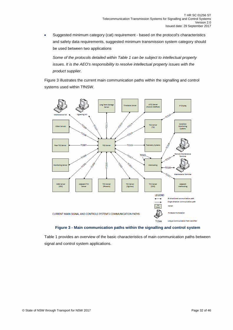
Figure 3 illustrates the current main communication paths within the signalling and control
systems used within TfNSW.
Figure 3 - Main communication paths within the signalling and control system
Table 1 provides an overview of the basic characteristics of main communication paths between
signal and control system applications.
© State of NSW through Transport for NSW 2017 Page 32 of 46

T HR SC 01256 ST Telecommunication Transmission Systems for Signalling and Control Systems
Version 2.0 Issued date: 29 September 2017
Table 1 – Guideline for main communication path within the signalling and control system
Id Description Type Protocol Timeout Availability Contains safety related data
Security Encryption Other IEC 62280 defences
Suggested minimum cat requirement
TCS01 SSIS IPC RSA SSS protocol NA S No None None No Cat 2
TCS02 Sig View System Serial /IP
SPG 01254 3 s S No Limited None No Cat 2
TCS03 Phoenix Serial /IP
SPG 01254 3 s S No Limited None No Cat 2
TCS04 Adjacent TCS IPC SPG 01254 200 ms VH Yes Limited None No Cat 1
TCS05 OSS IPC SPG 01254 200 ms H No Limited None No Cat 2
TCS06 Monitoring IPC Internal – 1 200 ms S No Limited None No Cat 2
TCS07 Peer TCS IPC Internal – 1 200 ms VH Yes Limited None No Cat 1
TCS08 Other servers IPC Various NA S No Limited Limited No Cat 2
TCS09 Maint WS IPC Internal – 1 200 ms H No Limited Limited No Cat 2
TCS10 Signalling WS IPC Internal – 1 200 ms VH Yes Limited Limited No Cat 1
TCS11 Storage IPC Internal – 1 200 ms S No Limited None No Cat 2
TCS12 Timetable server FTP FTP NA S No None None No Cat 2
TCS13 Future ATCS TBD TBD TBD TBD TBD TBD TBD TBD TBD
TCS14 Train describer IPC T HR SC 01251 SP 200 ms VH No Limited None No Cat 2
TCS15 Telemetry Serial BR1631 200 ms VH Yes None None No Cat 1
TCS15 Telemetry Serial BR1922 200 ms VH Yes None None No Cat 1
TCS15 Telemetry Serial Genisys 200 ms VH Yes Limited None No Cat 1
TCS16 IP display IPC Internal – 2 200 ms H No None None No Cat 2
TCS17 Interlockings Serial HDLC 200 ms VH Yes Limited None No Cat 1
© State of NSW through Transport for NSW 2017 Page 33 of 46

T HR SC 01256 ST Telecommunication Transmission Systems for Signalling and Control Systems
Version 2.0 Issued date: 29 September 2017
Id Description Type Protocol Timeout Availability Contains
safety related data
Security Encryption Other IEC 62280 defences
Suggested minimum cat requirement
TCS17 Interlockings Serial Modbus 200 ms VH Yes Limited None No Cat 1
TCS17 Interlockings Serial Genisys 200 ms VH Yes Limited None No Cat 1
TCS18 Condition monitoring TBD TBD TBD TBD TBD TBD TBD TBD TBD
TCS19 Remote terminal TBD TBD TBD TBD TBD TBD TBD TBD TBD
TCS20 Maintenance terminal
TBD TBD TBD TBD TBD TBD TBD TBD TBD
TCS21 Adjacent IXL TBD TBD TBD VH Yes Yes Yes Most Cat 1
TCS22 IXL internal TBD TBD TBD VH Yes Yes Yes Most Cat 1
© State of NSW through Transport for NSW 2017 Page 34 of 46
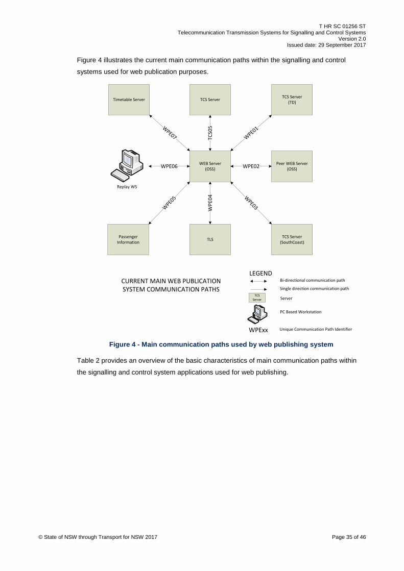
T HR SC 01256 ST Telecommunication Transmission Systems for Signalling and Control Systems
Version 2.0 Issued date: 29 September 2017
Figure 4 illustrates the current main communication paths within the signalling and control
systems used for web publication purposes.
WEB Server(OSS)
Timetable Server TCS Server TCS Server(TD)
TCS Server(SouthCoast)TLSPassenger
Information
Peer WEB Server(OSS)
Replay WS
WPE02
WPE
04
WPE06
TCS0
5
CURRENT MAIN WEB PUBLICATIONSYSTEM COMMUNICATION PATHS
TCS Server Server
LEGEND
PC Based Workstation
WPExx Unique Communication Path Identifier
WPE01
WPE03W
PE05
WPE07
Bi-directional communication path
Single direction communication path
Figure 4 - Main communication paths used by web publishing system
Table 2 provides an overview of the basic characteristics of main communication paths within
the signalling and control system applications used for web publishing.
© State of NSW through Transport for NSW 2017 Page 35 of 46

T HR SC 01256 ST Telecommunication Transmission Systems for Signalling and Control Systems
Version 2.0 Issued date: 29 September 2017
Table 2 - Guideline for main communication path for web publishing system
Id Description Type Protocol Timeout Availability Contains safety related data
Security Encryption Other IEC 62280 defences
Suggested minimum cat requirement
WSE01 Train describer IPC T HR SC 01251 SP 200 ms S No Limited None No Cat 2
WSE02 Peer OSS IPC Internal – 3 200 ms S No Limited None No Cat 2
WSE03 South Coast server IPC T HR SC 01251 SP 200 ms S No Limited None No Cat 2
WSE04 TLS IPC T HR SC 01251 SP 200 ms S No Limited None No Cat 2
WSE05 SPI IPC T HR SC 01251 SP 200 ms S No Limited None No Cat 2
WSE06 Replay work station IPC Internal – 3 200 ms S No Limited None No Cat 2
WSE07 Timetable server FTP FTP NA S No None None No Cat 2
© State of NSW through Transport for NSW 2017 Page 36 of 46

T HR SC 01256 ST Telecommunication Transmission Systems for Signalling and Control Systems
Version 2.0 Issued date: 29 September 2017
Figure 5 illustrates the draft communication paths within the proposed ATCS.
This figure represents the future state and so some communication paths are unknown.
Figure 5 – Draft future communication paths
Table 3 provides an overview of the basic characteristics of future communication paths within
the signalling and control system applications.
© State of NSW through Transport for NSW 2017 Page 37 of 46

T HR SC 01256 ST Telecommunication Transmission Systems for Signalling and Control Systems
Version 2.0 Issued date: 29 September 2017
Table 3 – Guideline for future communication path requirements
Id Description Type Protocol Timeout Availability Contains safety related data
Security Encryption Other IEC 62280 defences
Suggested minimum cat requirement
ATE01 Disaster recovery IPC TBD TBD TBD TBD TBD TBD TBD TBD
ATE02 Long term storage IPC TBD TBD TBD TBD TBD TBD TBD TBD
ATE03 Work station IPC TBD TBD TBD TBD TBD TBD TBD TBD
ATE04 Timetable server IPC TBD TBD TBD TBD TBD TBD TBD TBD
ATE05 OSS IPC TBD TBD TBD TBD TBD TBD TBD TBD
ATE06 RBC IPC TBD TBD TBD TBD TBD TBD TBD TBD
ATE07 Interlocking IPC TBD TBD TBD TBD TBD TBD TBD TBD
ATE08 RBC IXL IPC TBD TBD VH Yes Yes Yes Yes Cat 3
ATE09 RBC RBC IPC SubSet 098 v300 TBD VH Yes Yes Yes Yes Cat 3
ATE10 RBC Train IPC TBD TBD VH Yes Yes Yes Yes Cat 3
ATE11 Adjacent IXL IPC TBD TBD VH Yes Yes Yes Yes Cat 3
ATE12 Train detection system
IPC TBD TBD VH Yes Yes Yes Yes Cat 3
ATE13 Point system IPC TBD TBD VH Yes Yes Yes Yes Cat 3
ATE14 Level Crossing IPC TBD TBD VH Yes Yes Yes Yes Cat 3
ATE15 IXL IXL IPC TBD TBD VH Yes Yes Yes Yes Cat 3
ATE16 RBC Supporting systems
IPC TBD TBD VH TBD TBD TBD TBD TBD
ATE17 IXL Supporting systems
IPC TBD TBD VH TBD TBD TBD TBD TBD
© State of NSW through Transport for NSW 2017 Page 38 of 46

T HR SC 01256 ST Telecommunication Transmission Systems for Signalling and Control Systems
Version 2.0 Issued date: 29 September 2017
The following acronyms and abbreviations are used in Table 1, Table 2 and Table 3:
FTP file transfer protocol
Genisys serial protocol developed by Union Switch & Signal
HDLC high level data link control
H high availability – 99.995%
Internal - x protocol developed and used for the existing TfNSW's control systems
IP internet protocol
IXL interlocking
Limited not addressing all security threats as listed in IEC 62280
MODBUS serial protocol developed by Modicon
OSS operational system server
RBC radio block centre
RSA SSS station SCADA system interface protocol developed and used for the existing TfNSW's control systems
S standard availability - 99.99%
SP passenger information system
SSIS station SCADA (supervisory control and data acquisition) interface system
TCS traffic control system
TLS train location system
VH very high availability - 99.999%
© State of NSW through Transport for NSW 2017 Page 39 of 46

T HR SC 01256 ST Telecommunication Transmission Systems for Signalling and Control Systems
Version 2.0 Issued date: 29 September 2017
Appendix C General characteristics and categorisation of transmission systems
This appendix provides generic characteristics of transmission systems and an example of
classification of transmission systems. This appendix is based on simplified concepts and
configurations in order to provide simple examples and it should be used as guidance.
The current designs, existing implementations or new designs within the TfNSW network greatly
deviate from these simplifications. Therefore, each project or design should identify the
characteristics of the transmission system requirements including the complete system life cycle
and then produce a safety case in accordance with IEC 62280.
A generic categorisation of transmission systems against generic data communications hazards
can be done. However, specific or unique hazards for the particular protocol usage should be
identified for each communication path between the applications. If deviations from the generic
hazards and their treatments applicable to the transmission systems used within the complete
communication path are identified then those deviations should be analysed and mitigated.
If a communication path passes through a third party transmission system, including a public
switched telephone network (PSTN) or a leased line, then a safety case for the overall system
safety should also include those transmission systems.
If mixed telecommunication technologies are used within a communication path, then the
integrity, safety and security of the overall communication system should be determined by
considering all aspects of each transmission medium and any interface issues should be
identified between different transmission mediums.
The International Union Railways document, UIC IP Introduction to Railways – Guideline for the
fixed telecommunication network provides information on the different technologies used within
the railway environment, which can apply to TfNSW heavy rail network.
Appendix C.1 to Appendix C.4 explain the general features of different types of transmission
systems and the classification of these transmission systems based on their features.
This appendix does not identify hazards and their mitigation as the detailed configuration of the
transmission system is not known and their configuration can change over time.
C.1. Dedicated physical links The dedicated physical links should have the following general security and safety features and
should be demonstrated by evidence based detailed analysis:
• the equipment components and physical transmission mediums, such as cables, should be
located in secure places © State of NSW through Transport for NSW 2017 Page 40 of 46

T HR SC 01256 ST Telecommunication Transmission Systems for Signalling and Control Systems
Version 2.0 Issued date: 29 September 2017
• link has a simple and fixed configuration
• link can have a limited configuration change due to the static nature of the system
• the risk of unauthorised access is negligible
• the design and configuration should be fully documented and kept up to date, so that the
transmission system can be maintained adequately
A transmission system containing these security and safety features can be classified as
'category 1 and closed transmission system' in accordance with IEC 62280.
C.2. Circuit switched networks Circuit switched network is a type of telecommunications network in which users establish a
dedicated communications channel (circuit), which guarantees the full bandwidth of the channel
and remains connected for the duration of the communication session through the network
regardless of the channel used by the users.
Synchronous digital hierarchy (SDH) or asynchronous transfer mode (ATM) networks can
provide dedicated links between two locations. These technologies are proven old technologies
and are used extensively in Australia and other countries. They provide a dedicated
communication channel between two ends irrespective of whether actual communication is
taking place or not. The channel remains reserved and protected from competing users.
The circuit switched networks should have the following general security and safety features
and should be supported by evidence based detailed analysis:
• the equipment components and physical transmission mediums should be located in
secure places
• the design and configuration should be fully documented and kept up to date, so that the
transmission system can be maintained adequately
• network configuration is not simple
• network can have occasional configuration changes due to multiple user requirements
• the risk of unauthorised access is negligible
A transmission system containing these security and safety features can either be classified as
'category 1 and closed transmission system' or 'category 2 and open transmission system'
based on the safety case.
It cannot be classified as 'category 3 and open transmission system' as detailed in IEC 62280
as precondition 3 can be fulfilled satisfactorily.
© State of NSW through Transport for NSW 2017 Page 41 of 46

T HR SC 01256 ST Telecommunication Transmission Systems for Signalling and Control Systems
Version 2.0 Issued date: 29 September 2017
C.3. Packet switched networks Packet switched network is a networking communications method that groups all transmitted
data into suitably sized blocks, which are transmitted through a transmission medium that can
be shared by multiple simultaneous communication sessions.
The packet switched network is the preferred transmission medium and most of the
communications between locations happen using this transmission system due to its low cost
internet protocol (IP).
Messages used for this transmission system can be created as follows:
• the direct interface to a packet switched network
• serial communication can be converted into IP messages using a media converter
User datagram protocol (UDP) should not be used as a number of protocol defences
recommended in IEC 62280 cannot be supported.
Two generic packet switched configurations are analysed as examples in Appendix C.3.1 and
Appendix C.3.2.
C.3.1 Virtual private network The virtual private network (VPN) is a technology used within the packet switched network to
provide secure communication. A number of different VPN types are available and these are
implemented at different levels of OSI layers.
The virtual private network should have the following general security and safety features and
should be demonstrated by evidence based detailed analysis:
• the equipment components and physical transmission mediums should be located in
secure places
• the design and configuration should be fully documented and kept up to date, so that the
transmission system can be maintained adequately
• network configuration can be very complex and difficult to maintain the configuration data
• network configuration can change frequently due to multiple user requirements
• the risk of unauthorised access is negligible
A transmission system containing these security and safety features can either be classified as
'category 1 and closed transmission system' or 'category 2 and open transmission system'
based on the safety case.
It cannot be classified as 'category 3 and open transmission system' as detailed in IEC 62280
as precondition 3 can be fulfilled satisfactorily.
© State of NSW through Transport for NSW 2017 Page 42 of 46

T HR SC 01256 ST Telecommunication Transmission Systems for Signalling and Control Systems
Version 2.0 Issued date: 29 September 2017
C.3.2 Connectionless or connection oriented packet switching Packets are routed individually, sometimes resulting in different paths and out of order delivery.
The connectionless or connection oriented packet switched transmission system should have
the following general security and safety features and should be demonstrated by evidence
based detailed analysis:
• the equipment components and physical transmission mediums should be located in
secure places
• the design and configuration should be fully documented and kept up to date, so that the
transmission system can be maintained adequately
• network configuration can be very complex and difficult to maintain the configuration data
• network configuration can change very frequently due to multiple user requirements
• encryption is not used
• the risk of unauthorised access is not negligible
A transmission system containing these security and safety features can be classified as
'category 3 and open transmission system' as detailed in IEC 62280 as the requirements of
precondition 3 cannot be fulfilled satisfactorily.
C.4. Wireless Wireless transmission systems based on LIPD class licenced bands are detailed in
T MU TE 41004 ST Packet Switched Networks – Wireless Local Area Networks, including its
security and configuration requirements. It is recommended not to use 802.11 networks
including industrial, scientific and medical (ISM) band if the system requires high availability.
The wireless transmission system should have the following general security and safety
features and should be demonstrated by evidence based detailed analysis:
• wireless system's configuration can be very complex and difficult to maintain the
configuration data adequately
• the equipment and transmission medium used need not be securely protected
• wireless system can be open to interferences and shared by public – need not be valid to
licenced bands
• wireless system's configuration can change frequently due to multiple user requirements
• some part of the communication path cannot provide physical security
• the risk of unauthorised access is not negligible
© State of NSW through Transport for NSW 2017 Page 43 of 46

T HR SC 01256 ST Telecommunication Transmission Systems for Signalling and Control Systems
Version 2.0 Issued date: 29 September 2017
A transmission system containing these security and safety features can be classified as
'category 3 and open transmission system' as detailed in IEC 62280 as the requirements of
precondition 3 cannot be fulfilled satisfactorily.
© State of NSW through Transport for NSW 2017 Page 44 of 46

T HR SC 01256 ST Telecommunication Transmission Systems for Signalling and Control Systems
Version 2.0 Issued date: 29 September 2017
Appendix D Threats and defences analysis example
This appendix contains one worked example of identified threats and defences in a signalling
control systems interface for guidance purposes.
The example, provided in this Appendix is informative only regardless of whether it is used for
safety related functions.
The following example is based on T HR SC 01251 SP Signalling Control Systems Interface
Requirements, which can be used for interface between control systems and external systems.
Based on that document, the protocols' in-built defences are listed within the 'defensive protocol
characteristics' column in Table 4.
As the protocol has no adequate defences against corruption and masquerade threats,
applications using this protocol should be using Category 1 transmission systems. Adding
external defences such as encryption still cannot provide adequate defences.
Based on the functions performed by the applications, less stringent transmission systems can
be used as long as there is evidence based supporting analysis, such as safety case.
Table 4 – Threats and defences for signalling control systems
Threats Defensive protocol characteristics Additional defences
Repetition Message handshaking Session number Established channel
None
Deletion Message handshaking Session number Established channel
None
Insertion Message handshaking Source and destination identifiers Established channel
None
Re sequence Session number Established channel
None
Corruption Limited CRC None
Delay Timeout mechanism None
Masquerade None Encryption
© State of NSW through Transport for NSW 2017 Page 45 of 46

T HR SC 01256 ST Telecommunication Transmission Systems for Signalling and Control Systems
Version 2.0 Issued date: 29 September 2017
Appendix E Communication path presentation example
Figure 6 provides an example of a representation of communication path characteristics. In this
example redundant communication path arrangement path A and path B is shown in order to
connect system A at location A and system B at location B.
This example is provided as a suggestion only. AEOs may present the required information in
accordance with their own processes and procedures.
System B at
Location B
System AAt
Location A
No diversity
Cable diversity
Duct diversity
Route diversity
CXn
EXn
PXn
Full Diversity
Partial Diversity
No DiversityNXn
Network core connection point (if used)
Network points-of-presence (if used)
Network distribution-edge (if used)
Intermediate nodes
Full diversity
CR11CR10 CR12
CR5 CR7CR2CR1 CR3 CR4 CR8 CR9
CR13
A B AB
E1
C1
N4P1aN2a E2P1b P2bN3a
N3 N2b
CR14 CR15:1
N1b
N5
C2CR6P2aN1a
N3b
Link A = CR{4,3,2,1,10,11,12,13,14,15,9,8,7}Link B = CR{5,6}
Telecommunication Cable Diversity
Network Diversity
© State of NSW through Transport for NSW 2017 Page 46 of 46
Figure 6 - Communication path characteristics example


![C04 wireless telecommunication-systems[1]](https://img.dokumen.tips/doc/110x75/5581ebb4d8b42a67508b493e/c04-wireless-telecommunication-systems1.jpg)