Embed Size (px)
Citation preview

T-FLEX Parametric CAD is a full-function software system providing
mechanical design professionals with the tools they need for today's
complex design challenges. It unites powerful parametric 3D
modeling functionality with the parametric drafting and drawing
production toolset.

T-FLEX modeling and assembly tools enable to easily develop
a full range of products, from single parts to assemblies
containing thousands of components.
Highly innovative parametric modeling tools allow
designers to quickly create basic shapes and easily add
common mechanical features.
T-FLEX harnesses the power of Parasolid® production - proven
modeling kernel developed by Siemens PLM Software.
Modeling Tools

You use a common set of editing and data management
functions on all types of geometry, streamlining workflow.
T-FLEX supports a simple unified mode of operations
for all types of documents and entities:
Drawings
Assembly drawings
Solids
Surfaces
Parts
Parts with multiple solid bodies
Assembly models
Sheet metal
Bill of materials
etc.
!
Design Workflow

Unlike other products, T-FLEX lets you create
parametric 2D drawings from scratch.
T-FLEX has a much more robust palette of 2D
tools.
Its parametric engine is the basis of T-FLEX
design and unlike engines from other
programs is not limited by the number of
constrained 2D entities.
The drawing immediately updates to any
changes regardless of their source.
T-FLEX includes fully parametric drawing
documentation, including dimensions,
tolerances, text, and drawing notes.
The result can be fully automatic, so that a master parametric drawing does
not require any editing as changes are required.
!
Parametric Drafting
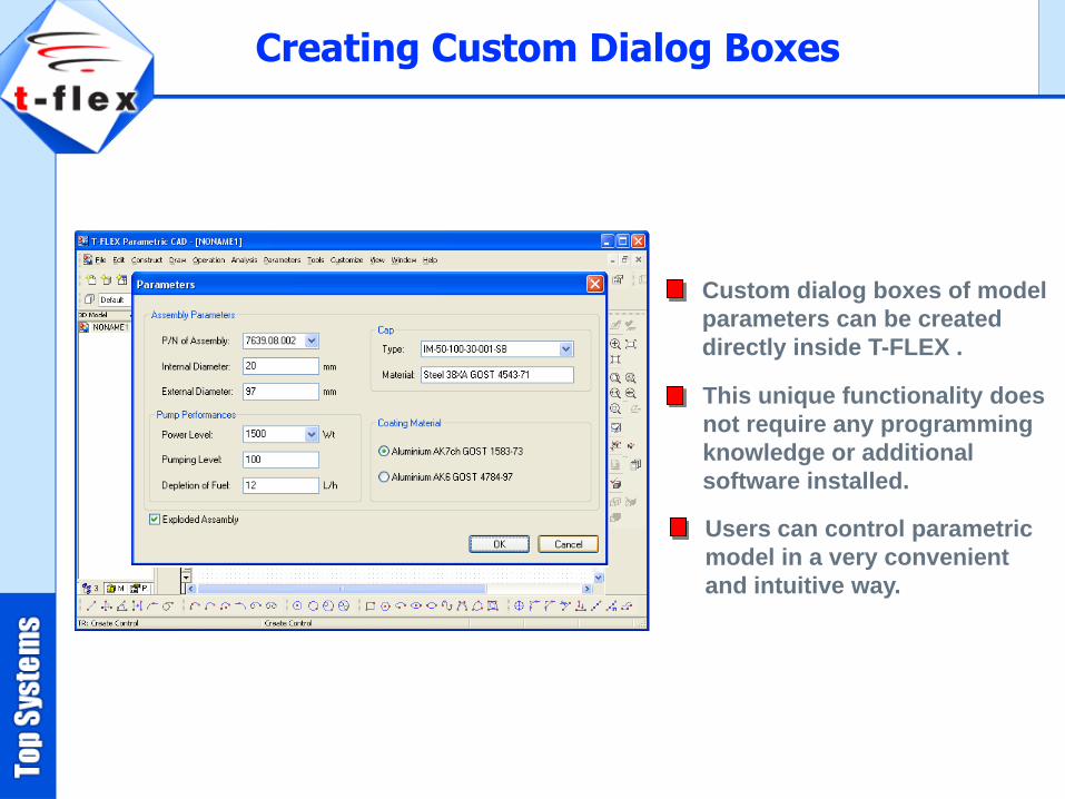
Custom dialog boxes of model
parameters can be created
directly inside T-FLEX .
This unique functionality does
not require any programming
knowledge or additional
software installed.
Users can control parametric
model in a very convenient
and intuitive way.
Creating Custom Dialog Boxes
ParametersVariables Editor
User’s dialog
Variables
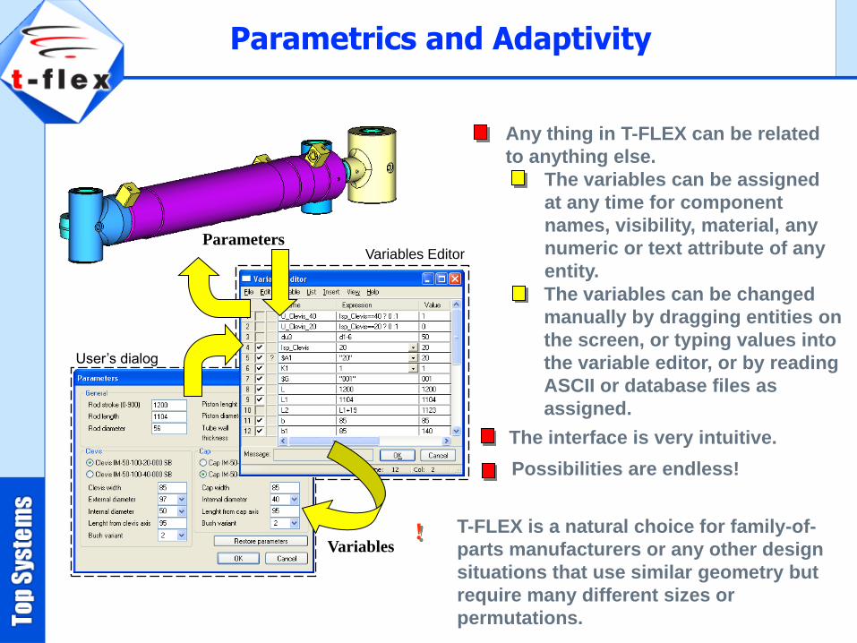
Any thing in T-FLEX can be related
to anything else.
The variables can be assigned
at any time for component
names, visibility, material, any
numeric or text attribute of any
entity.
The variables can be changed
manually by dragging entities on
the screen, or typing values into
the variable editor, or by reading
ASCII or database files as
assigned.
Possibilities are endless!
The interface is very intuitive.
T-FLEX is a natural choice for family-of-
parts manufacturers or any other design
situations that use similar geometry but
require many different sizes or
permutations.
!
Parametrics and Adaptivity

The interface is easy to
learn and very consistent.
The incredible flexibility of
design automation using
parametric functionality.
The program's Total Flexibility
approach can truly eliminate
redundant tasks and enhance
design efficiency.
T-FLEX is a Creative Tool

T-FLEX easily tackles assembly 3D models.
You can build complex assemblies
consisting of many components.
Using bottom-up design, top-down design,
or a combination of both methods.
Configuration management helps to
simplify design reuse by creating
multiple product variations within a
single document.
Assembly Modeling
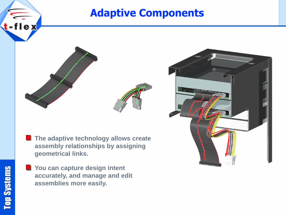
The adaptive technology allows create
assembly relationships by assigning
geometrical links.
You can capture design intent
accurately, and manage and edit
assemblies more easily.
Adaptive Components

Users create their own modeling
features.
T-FLEX models may capture
elements and geometry from other
models as input parameters of
operations inside their own model
history tree.
Any T-FLEX model can be defined
as a special feature that will
function equally with other
modeling commands.
This mechanism can dramatically
reduce the modeling time.
!
User-defined Features
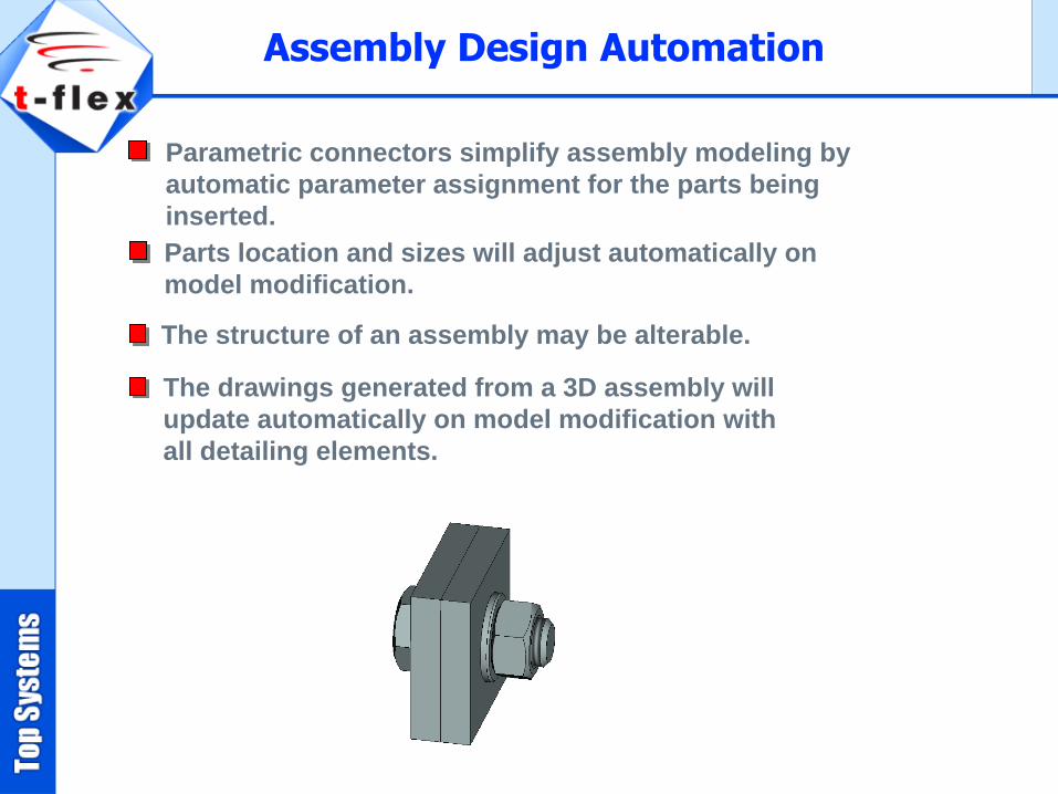
Parametric connectors simplify assembly modeling by
automatic parameter assignment for the parts being
inserted.
Parts location and sizes will adjust automatically on
model modification.
The structure of an assembly may be alterable.
Assembly Design Automation
The drawings generated from a 3D assembly will
update automatically on model modification with
all detailing elements.

T-FLEX synergistically combines solid and surface
modeling.
Designers can extrude, sweep, revolve, and loft
surfaces as can be done with solid models.
It enables to do things that can't be done
with parametric solids alone.
Integrated surface and solid modeling
provides flexibility in making design.
Surfacing

The set of deformation commands provide a simple way
to change shapes of complex surface or solid models.
Deformation may be applied either in a local
area or globally.
Various options may be specified by direct rules
and parameters or via the special handlers.
Deformation Commands
Fast preview based on input data is available
prior to exact model generation.

T-FLEX supports direct editing of 3D models, retaining
history of the edits so that they can be regenerated.
It is possible to modify parameters of the faces
whose underlying surfaces are analytical.
Modify parameters of faces
created as blends
Imprinting
Face replacement
Face extension
Face removing
Body separation
etc.
Imported model
Direct Editing
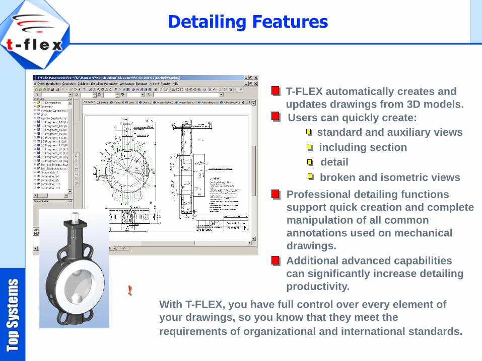
T-FLEX automatically creates and
updates drawings from 3D models.
Users can quickly create:
With T-FLEX, you have full control over every element of
your drawings, so you know that they meet the
requirements of organizational and international standards.
!
Professional detailing functions
support quick creation and complete
manipulation of all common
annotations used on mechanical
drawings.
Additional advanced capabilities
can significantly increase detailing
productivity.
standard and auxiliary views
including section
detail
broken and isometric views
Detailing Features

T-FLEX can generate and update an accurate BOM.
Part and subassembly quantities are always kept up to date, and
are instantly organized and populated into a drawing BOM.
Changes to the assembly are associative BOM table is updated automatically.
BOM templates and table properties are fully customizable.
Associative Bill of Materials (BOM)

T-FLEX provides a set of commands tailored for
the efficient construction of sheet metal parts
from design of sheet metal components to flat
pattern development and the creation of
engineering drawings.
Bend
Unbend
Re-bend
Forming Feature
Sheet Metal Design
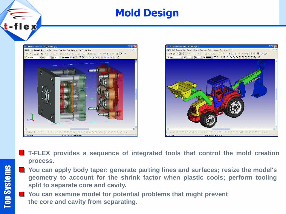
You can apply body taper; generate parting lines and surfaces; resize the model's
geometry to account for the shrink factor when plastic cools; perform tooling
split to separate core and cavity.
T-FLEX provides a sequence of integrated tools that control the mold creation
process.
You can examine model for potential problems that might prevent
the core and cavity from separating.
Mold Design

More advanced analysis capabilities are available within the T-FLEX Analysis line of
products.
Built-in Express Analysis offers an easy-to-use first pass stress analysis tool that
enables design engineers to execute design verification directly in T-FLEX.
Express Analysis uses the same design analysis technology that professional FEA add-on
module uses to perform stress analysis.
It helps to determine how designs will perform under real-world conditions, and identify
potential design flaws before expensive physical prototypes are built.
Express FEA

T-FLEX Open API is based on .NET technology offering customers and third-party
developers extensive possibilities for developing add-on applications in various areas.
T-FLEX Open API supports full object oriented programming concepts and multiple
programming languages with identical functional access to all T-FLEX functionality.
It also helps users to customize T-FLEX for their specific environment and automate
specialized workflows.
Open API

Using T-FLEX and T-FLEX Open API, third parties, OEMs, developers, and
system integrators can deliver parametric CAD functionality across a wide
range of Internet-based products.
T-FLEX can be utilized as an Internet
engine.
Provides engineers, manufacturers
and distributors with opportunity to
display their products.
Uses third-party designs.
Performs marketing
activities.
!
Parametric Engine for Internet
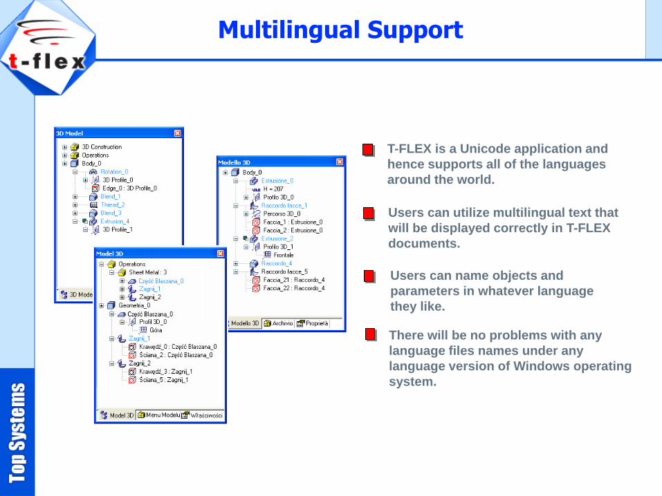
T-FLEX is a Unicode application and
hence supports all of the languages
around the world.
Users can utilize multilingual text that
will be displayed correctly in T-FLEX
documents.
Users can name objects and
parameters in whatever language
they like.
There will be no problems with any
language files names under any
language version of Windows operating
system.
Multilingual Support

T-FLEX's multiple interface options help maximize productivity by allowing users
to choose an interface that matches their experience and preferences.
The Windows-style pull-down menu
interface is easy to navigate.
Compact text-based command bar, icon
toolbars and shortcut key assignments are
also available.
Enhanced capabilities, such as intelligent
positioning tools and pop-up menus driven
by hot key activation, greatly simplify
workflow.
T-FLEX provides direct model interaction,
using 3rd mouse button, dynamic geometry
preview, and support for SpaceMouse® to
seamlessly blend frequent and advanced
capabilities.
Interface Flexibility

Additionally, T-FLEX provides options for exporting graphical
images to presentations, web pages, and other documentation.
T-FLEX is interoperable with the most
widely used 3D-modeling and 2D-drawing
systems via the following formats:
Parasolid
IGES
STEP
Rhino
STL
DWG
DXF
SolidWorks
The rich suite of T-FLEX translators enables you to satisfy
differing import and export requirements, effortlessly.
Translators
Solid Edge
Inventor
etc

T-FLEX CAM in combination with T-FLEX CAD offers a fully
integrated parametric solution for design and manufacturing.
The base module of T-FLEX 3D CAM system contains:
The mathematical core integrated with the
mathematical core of Parasolid platform;
The tool editor for designing the tools employed
for machining a specific part, and for building
tool databases;
The postprocessor generation module that allows
creating custom postprocessors, using tabulated
settings, macros or actual programming;
The library of postprocessors including about 250
predefined postprocessors for:
The machining simulator showing the machining
process according to the generated control
sequence without the material removal;
T-FLEX NC Tracer, a simulation application, allows T-FLEX CAM to
interactively verify the machine codes and machine operations.
Wire EDM Laser Turning Drilling
(2.5D, 5D)
Milling
(2.5D, 3D, 5D )
T-FLEX CAM
Punching

T-FLEX Analysis offers a wide spectrum of powerful tools to help
engineers to perform virtual testing and analysis for predicting the
physical behavior under various loading conditions.
T-FLEX Analysis shows how a model will perform
under real-world conditions before it is built.
Linear static studies calculate displacements,
reaction forces, strains, stresses, and factor of
safety distribution.
Frequency analysis calculates the natural
frequencies and the associated mode shapes.
Buckling studies help avoid failure due to buckling
which refers to sudden large displacements due to
axial loads.
Thermal studies calculate temperatures,
temperature gradients, and heat flow based on
heat generation, conduction, convection, and
radiation conditions.
T-FLEX Analysis provides easy-to-use yet powerful design analysis tools
for designers and engineers that help them improve design quality, avoid
field failures, reduce material costs, and shorten time-to-market.
!
T-FLEX Analysis

Minimum:
Microsoft® Windows® 2000, XP, 2003 Server, Vista
32 bit or 64 bit
Intel® Pentium IV – 1Ghz or equivalent
250 MB hard disk space
Recommended:
2 GB memory (RAM) or more for large assemblies
OpenGL Graphics Accelerator
T-FLEX Requirements

Your Partner
3D CAD CAM TECHNOLOGY Inc.
TURKEY- ISTANBUL
www.3dcadcam.com.tr
T-FLEX Parametric CAD, T-FLEX CAD, T-FLEX CAM, T-FLEX Analysis are trademarks of Top Systems.
All other logos, trademarks or service marks used herein are the property of their respective owners.
Copyright © 2008 Top Systems, All rights reserved.