Embed Size (px)
Citation preview
IEC 62271-111 Edition 2.0 2012-09
INTERNATIONAL STANDARD
High-voltage switchgear and controlgear – Part 111: Automatic circuit reclosers and fault interrupters for alternating current systems up to 38 kV
IEC
622
71-1
11:2
012(
E)
IEE
E S
td. C
37.6
0-20
12
IEEE C37.60™
colourinside
http://qstandard.org/

THIS PUBLICATION IS COPYRIGHT PROTECTED Copyright © 2012 IEEE All rights reserved. IEEE is a registered trademark in the U.S. Patent & Trademark Office, owned by the Institute of Electrical and Electronics Engineers, Inc. Unless otherwise specified, no part of this publication may be reproduced or utilized in any form or by any means, electronic or mechanical, including photocopying and microfilm, without permission in writing from the IEC Central Office. Any questions about IEEE copyright should be addressed to the IEEE. Enquiries about obtaining additional rights to this publication and other information requests should be addressed to the IEC or your local IEC member National Committee.
IEC Central Office Institute of Electrical and Electronics Engineers, Inc. 3, rue de Varembé 3 Park Avenue CH-1211 Geneva 20 New York, NY 10016-5997 Switzerland United States of America Tel.: +41 22 919 02 11 [email protected] Fax: +41 22 919 03 00 www.ieee.org [email protected] www.iec.ch
About the IEC The International Electrotechnical Commission (IEC) is the leading global organization that prepares and publishes International Standards for all electrical, electronic and related technologies.
About IEC publications The technical content of IEC publications is kept under constant review by the IEC. Please make sure that you have the latest edition, a corrigenda or an amendment might have been published. Useful links: IEC publications search - www.iec.ch/searchpub The advanced search enables you to find IEC publications by a variety of criteria (reference number, text, technical committee,…). It also gives information on projects, replaced and withdrawn publications. IEC Just Published - webstore.iec.ch/justpublished Stay up to date on all new IEC publications. Just Published details all new publications released. Available on-line and also once a month by email.
Electropedia - www.electropedia.org The world's leading online dictionary of electronic and electrical terms containing more than 30 000 terms and definitions in English and French, with equivalent terms in additional languages. Also known as the International Electrotechnical Vocabulary (IEV) on-line. Customer Service Centre - webstore.iec.ch/csc If you wish to give us your feedback on this publication or need further assistance, please contact the Customer Service Centre: [email protected].
http://qstandard.org/

IEC 62271-111 Edition 2.0 2012-09
INTERNATIONAL STANDARD
High-voltage switchgear and controlgear – Part 111: Automatic circuit reclosers and fault interrupters for alternating current systems up to 38 kV
INTERNATIONAL ELECTROTECHNICAL COMMISSION XF ICS 29.130.10
PRICE CODE
ISBN 978-2-83220-332-3
Warning! Make sure that you obtained this publication from an authorized distributor.
IEEE C37.60™
colourinside
http://qstandard.org/

– 2 – IEC 62271-111:2012(E) IEEE Std C37.60-2012(E)
Published by IEC under license from IEEE. © 2012 IEEE. All rights reserved.
CONTENTS
FOREWORD ......................................................................................................................... 11 1 Overview ........................................................................................................................ 14
Scope .................................................................................................................... 14 1.1 Normative references ............................................................................................ 14 1.2
2 Normal and special service conditions ............................................................................ 15 2.101 General .......................................................................................................... 15 2.102 Normal service conditions .............................................................................. 16 2.102.1 Indoor switchgear and controlgear ................................................................. 16 2.102.2 Outdoor switchgear and controlgear ............................................................... 16 2.103 Special service conditions .............................................................................. 17 2.103.1 General .......................................................................................................... 17 2.103.2 Altitude .......................................................................................................... 17 2.103.3 Pollution ......................................................................................................... 17 2.103.4 Temperature and humidity .............................................................................. 18 2.103.5 Vibrations, shock, or tilting ............................................................................. 18 2.103.6 Wind speed .................................................................................................... 18 2.103.7 Other special (unusual) service conditions .................................................... 18
3 Terms and definitions ..................................................................................................... 18 General terms ....................................................................................................... 19 3.1 Assemblies of switchgear and controlgear ............................................................. 21 3.2 Parts of assemblies ............................................................................................... 21 3.3 Switching devices .................................................................................................. 21 3.4 Parts of switchgear and controlgear ...................................................................... 21 3.5 Operation .............................................................................................................. 21 3.6 Characteristic quantities ........................................................................................ 22 3.7 Index of definitions ................................................................................................ 23 3.8
4 Ratings ........................................................................................................................... 23 Rated voltage (Ur) ................................................................................................. 24 4.1 Rated insulation level ............................................................................................ 25 4.2 Rated frequency (fr) .............................................................................................. 26 4.3 Rated normal current and temperature rise............................................................ 26 4.4
Rated normal current (Ir) ........................................................................... 26 4.4.1 Temperature rise ....................................................................................... 27 4.4.2 Particular points of Table 4 ........................................................................ 29 4.4.3
Rated short-time withstand current (Ik) .................................................................. 30 4.5 Rated peak withstand current (Ip) .......................................................................... 31 4.6 Rated duration of short-circuit (tk) ......................................................................... 31 4.7 Rated supply voltage of closing and opening devices and of auxiliary and 4.8
control circuits (Ua) ............................................................................................... 31 Rated supply frequency of closing and opening devices and of auxiliary 4.9
circuits .................................................................................................................. 31 Rated pressure of compressed gas supply for controlled pressure systems ........... 31 4.10 Rated filling levels for insulation and/or operation.................................................. 31 4.11
4.101 Rated minimum tripping current (I>min) ........................................................... 31 4.102 Rated symmetrical interrupting current (short-circuit breaking current) ........... 32
http://qstandard.org/

IEC 62271-111:2012(E) – 3 – IEEE Std C37.60-2012(E)
Published by IEC under license from IEEE. © 2012 IEEE. All rights reserved.
4.103 Transient recovery voltage related to rated symmetrical interrupting current ........................................................................................................... 32
4.103.1 General .......................................................................................................... 32 4.103.2 Representation of TRV waves ........................................................................ 32 4.103.3 Representation of TRV ................................................................................... 33 4.103.4 Standard values of TRV related to the rated short-circuit breaking
current ........................................................................................................... 34 4.103.4.1 General .......................................................................................................... 34 4.103.4.2 First-pole-to-clear factor (kpp) ......................................................................... 35 4.103.4.3 Rate of rise of recovery voltage (RRRV) ......................................................... 36 4.104 Rated symmetrical making current (short-circuit making current) .................... 43 4.105 Rated operating sequence ............................................................................. 45 4.106 Rated line and cable charging interrupting currents ........................................ 45
5 Design and construction ................................................................................................. 45 Requirements for liquids in switchgear and controlgear ......................................... 45 5.1
Liquid level ................................................................................................ 45 5.1.1 Liquid quality ............................................................................................. 46 5.1.2 Oil sampling provision (submersible reclosers/FIs) .................................... 46 5.1.3
Requirements for gases in switchgear and controlgear .......................................... 46 5.2 Earthing of switchgear and controlgear .................................................................. 46 5.3 Auxiliary and control equipment ............................................................................. 46 5.4 Dependent power operation ................................................................................... 46 5.5 Stored energy operation ........................................................................................ 46 5.6 Independent manual operation or power operation (independent unlatched 5.7
operation) .............................................................................................................. 46 Operation of releases ............................................................................................ 47 5.8
Shunt closing release ................................................................................ 47 5.8.1 Shunt opening release ............................................................................... 47 5.8.2 Capacitor operation of shunt releases ....................................................... 47 5.8.3 Under-voltage release ............................................................................... 47 5.8.4
Low- and high- pressure interlocking devices and monitoring devices ................... 47 5.9 Nameplates ........................................................................................................... 48 5.10 Interlocking devices ............................................................................................... 49 5.11 Position indication ................................................................................................. 50 5.12 Degrees of protection provided by enclosures ....................................................... 50 5.13
Protection of persons against access to hazardous parts and 5.13.1protection of the equipment against ingress of solid foreign objects (IP coding) ................................................................................ 50
Protection against ingress of water (IP coding) ..................................... 50 5.13.2 Protection of equipment against mechanical impact under normal 5.13.3
service conditions (IK coding) ............................................................... 50 Enclosure design and coating system requirements .............................. 50 5.13.101
Creepage distances for outdoor insulators ............................................................. 50 5.14 Gas and vacuum tightness .................................................................................... 51 5.15
Controlled pressure systems for gas ..................................................... 51 5.15.1 Closed pressure systems for gas .......................................................... 51 5.15.2 Sealed pressure systems ...................................................................... 51 5.15.3
Design and withstand ............................................................................ 51 5.15.101 Leak rate .............................................................................................. 51 5.15.102
http://qstandard.org/

– 4 – IEC 62271-111:2012(E) IEEE Std C37.60-2012(E)
Published by IEC under license from IEEE. © 2012 IEEE. All rights reserved.
Liquid tightness ..................................................................................................... 52 5.16 Fire hazard (flammability) ...................................................................................... 52 5.17 Electromagnetic compatibility (EMC) ..................................................................... 52 5.18 X-ray emission ...................................................................................................... 52 5.19
Tank construction: submersible or dry vault reclosers/FIs ................................... 52 5.101 Tank material and finish ........................................................................ 52 5.101.1 Water entrapment ................................................................................. 52 5.101.2 Tank support ......................................................................................... 52 5.101.3 Lifting lugs ............................................................................................ 52 5.101.4
Counters ............................................................................................................. 52 5.102 Conductor terminal sizes .................................................................................... 52 5.103 Stored mechanism charge indicator .................................................................... 53 5.104
6 Type tests ...................................................................................................................... 53 General ................................................................................................................. 53 6.1
Grouping of tests ....................................................................................... 53 6.1.1 Information for identification of specimens ................................................. 54 6.1.2 Information to be included in type-test reports ........................................... 54 6.1.3
Test conditions .......................................................................................... 55 6.1.101 Dielectric tests ...................................................................................................... 56 6.2
Ambient air conditions during tests ............................................................ 56 6.2.1 Wet test procedure .................................................................................... 56 6.2.2 Conditions of switchgear and controlgear during dielectric tests ................ 56 6.2.3 Criteria to pass the test ............................................................................. 57 6.2.4 Application of the test voltage and test conditions ..................................... 57 6.2.5 Tests of switchgear and controlgear of Ur ≤ 245 kV ................................... 57 6.2.6 Test of switchgear and controlgear of Ur > 245 kV ..................................... 58 6.2.7 Artificial pollution tests for outdoor insulators............................................. 58 6.2.8
Radio intereference voltage (r.i.v.) test .................................................................. 58 6.3 Measurement of the resistance of circuits .............................................................. 58 6.4
Main circuit ................................................................................................ 58 6.4.1 Auxiliary circuits ........................................................................................ 59 6.4.2
Temperature-rise tests .......................................................................................... 59 6.5 Condition of the switchgear and controlgear to be tested ........................... 59 6.5.1 Arrangement of the equipment ................................................................... 59 6.5.2 Measurement of the temperature and the temperature rise ........................ 60 6.5.3 Ambient air temperature ............................................................................ 60 6.5.4 Temperature-rise test of the auxiliary and control equipment ..................... 60 6.5.5 Interpretation of the temperature-rise tests ................................................ 61 6.5.6
Short time withstand current and peak withstand current tests ............................... 61 6.6 Verification of the protection .................................................................................. 61 6.7 Tightness tests ...................................................................................................... 61 6.8
Controlled pressure systems for gas .......................................................... 61 6.8.1 Closed pressure systems for gas ............................................................... 61 6.8.2 Sealed pressure systems ........................................................................... 62 6.8.3 Liquid tightness tests ................................................................................. 62 6.8.4
Electromagnetic compatibility tests (EMC) ............................................................. 62 6.9 Additional tests on auxiliary and control circuits .................................................... 62 6.10
http://qstandard.org/

IEC 62271-111:2012(E) – 5 – IEEE Std C37.60-2012(E)
Published by IEC under license from IEEE. © 2012 IEEE. All rights reserved.
X-radiation test procedure for vacuum interrupters ................................................ 62 6.11 Line charging current and cable charging current interruption tests..................... 62 6.101
Applicability ...................................................................................... 62 6.101.1 General ............................................................................................ 63 6.101.2 Characteristics of supply circuits ...................................................... 63 6.101.3 Earthing (grounding) of the supply circuit.......................................... 63 6.101.4 Characteristics of the capacitive circuit to be switched ..................... 64 6.101.5 Waveform of the current ................................................................... 64 6.101.6 Test voltage ..................................................................................... 64 6.101.7 Test current ...................................................................................... 65 6.101.8 Test-duties ....................................................................................... 65 6.101.9
Criteria to pass the test .................................................................... 67 6.101.10 Making current capability .................................................................................... 67 6.102
Test procedure ...................................................................................... 67 6.102.1 Criteria for passing making current tests ............................................... 67 6.102.2
Rated symmetrical interrupting current tests ....................................................... 67 6.103 General ................................................................................................. 67 6.103.1 Interrupting performance ....................................................................... 69 6.103.2 Verification of rated symmetrical interrupting current ............................. 69 6.103.3 Standard operating duty test; automatic operation................................. 70 6.103.4 Operating duty test; non-reclosing fault interrupters .............................. 71 6.103.5 Condition of recloser/FI after operating duty test ................................... 71 6.103.6
Critical current tests ........................................................................................... 71 6.104 Applicability .......................................................................................... 71 6.104.1 Test current .......................................................................................... 71 6.104.2 Critical current test-duty ........................................................................ 71 6.104.3
Minimum tripping current tests ............................................................................ 72 6.105 Test circuit ............................................................................................ 72 6.105.1 Test procedures .................................................................................... 72 6.105.2
Partial discharge (corona) tests .......................................................................... 72 6.106 Test voltages and limits ........................................................................ 72 6.106.1 Conditioning of test sample ................................................................... 72 6.106.2 Test equipment and procedure .............................................................. 72 6.106.3 Partial discharge test report .................................................................. 73 6.106.4
Surge current test; series-trip reclosers/FIs ........................................................ 73 6.107 General ................................................................................................. 73 6.107.1 Test conditions ..................................................................................... 73 6.107.2 Test procedure ...................................................................................... 73 6.107.3 Condition after test................................................................................ 74 6.107.4
Time-current tests............................................................................................... 74 6.108 Test conditions ..................................................................................... 74 6.108.1 Test procedure ...................................................................................... 74 6.108.2 Presentation of data standard time-current curves ................................ 74 6.108.3
Mechanical duty test ........................................................................................... 75 6.109 General ................................................................................................. 75 6.109.1 Mechanical duty test ............................................................................. 75 6.109.2 Condition of recloser/FI following mechanical operation test ................. 75 6.109.3
http://qstandard.org/

– 6 – IEC 62271-111:2012(E) IEEE Std C37.60-2012(E)
Published by IEC under license from IEEE. © 2012 IEEE. All rights reserved.
Ice loading test ................................................................................................... 76 6.110 General ................................................................................................. 76 6.110.1 Applicability .......................................................................................... 76 6.110.2 Ice formations ....................................................................................... 76 6.110.3 Test program ........................................................................................ 76 6.110.4 Acceptance criteria ............................................................................... 78 6.110.5
Control electronic elements surge withstand capability (SWC) tests .................... 79 6.111 General ................................................................................................. 79 6.111.1 Oscillatory and fast transient surge tests ............................................... 79 6.111.2 Simulated surge arrester operation test ................................................. 79 6.111.3
Condition of recloser/FI after each test of 6.101, 6.103 and 6.104 ...................... 81 6.112 General requirements ........................................................................... 81 6.112.1 Specific requirement for vacuum interrupters in SF6 insulated 6.112.2
equipment ............................................................................................. 82 7 Routine tests .................................................................................................................. 82
Dielectric test on the main circuit ........................................................................... 83 7.1 Tests on auxiliary and control circuits .................................................................... 83 7.2 Measurement of the resistance of the main circuit ................................................. 83 7.3 Tightness test ........................................................................................................ 83 7.4
Sealed pressure systems ........................................................................... 83 7.4.1 Liquid tightness tests ................................................................................. 83 7.4.2
Reclosing and overcurrent trip calibration ........................................................... 84 7.101 Partial discharge test .......................................................................................... 84 7.102 Mechanical operations tests ............................................................................... 84 7.103
8 Guide to the selection of switchgear and controlgear ...................................................... 84 9 Information to be given with enquiries, tenders and orders ............................................. 85 10 Transport, storage, installation, operation and maintenance ........................................... 85 11 Safety ............................................................................................................................. 85 12 Influence of the product on the environment ................................................................... 85 101 Additional application and test information ...................................................................... 85
Field tests on units in-service, including d.c. withstand tests on cables ............... 85 101.1 Internal arc classification .................................................................................... 86 101.2
Annex A (informative) X/R Ratios ......................................................................................... 87 A.1 General ................................................................................................................. 87 A.2 Time constant τ and X/R ratio ................................................................................ 87 A.3 Asymmetrical fault current ..................................................................................... 87
Annex B (informative) Simulated surge arrester operation test ............................................. 89 B.1 General ................................................................................................................. 89 B.2 Simulated surge arrester operation testing ............................................................ 89
Annex C (normative) Method of drawing the envelope of the prospective transient recovery voltage of a circuit and determining the representative parameters ......................... 93
C.1 General ................................................................................................................. 93 C.2 Drawing the envelope ............................................................................................ 93 C.3 Determination of parameters ................................................................................. 93
Annex D (informative) Background basis of recloser TRV values ......................................... 95 D.1 General ................................................................................................................. 95
http://qstandard.org/

IEC 62271-111:2012(E) – 7 – IEEE Std C37.60-2012(E)
Published by IEC under license from IEEE. © 2012 IEEE. All rights reserved.
D.2 Two parameter TRV .............................................................................................. 95 D.3 uc (TRV peak) ....................................................................................................... 97 D.4 Rate of rise of recovery voltage (RRRV) ................................................................ 98 D.5 t3 (time to reach uc at the specified RRRV) ........................................................... 98 D.6 Multipliers for TRV values at currents less than the rated short-circuit current ....... 98
Annex E (normative) Tolerances for test values ................................................................. 100 E.1 General ............................................................................................................... 100 E.2 Type test tolerances ............................................................................................ 100
Annex F (informative) Definition for the automatic circuit recloser ...................................... 103 F.1 Definition of a recloser ........................................................................................ 103 F.2 Background ......................................................................................................... 103 F.3 Recloser classifications ....................................................................................... 103 F.4 Recloser operating characteristics ....................................................................... 104
Annex G (informative) Definition for the fault interrupter .................................................... 105 G.1 Definition of a fault interrupter ............................................................................. 105 G.2 Background ......................................................................................................... 105 G.3 Fault interrupter application ................................................................................. 105
Annex H (informative) Basis of derivation of duty factors and standard operating duties ................................................................................................................................. 106
H.1 General ............................................................................................................... 106 H.2 Standard operating duty ...................................................................................... 106
Annex I (normative) Ratings for oil interrupting reclosers and hydraulically controlled reclosers ............................................................................................................................. 109
I.1 General ............................................................................................................... 109 I.2 Rating structure for hydraulically controlled series-trip and oil interrupting
reclosers ............................................................................................................. 109 I.2.1 General ................................................................................................... 109 I.2.2 Rated maximum voltage .......................................................................... 109 I.2.3 Rated continuous (normal) current (Ir) ..................................................... 109 I.2.4 Rated minimum tripping current for hydraulically controlled series-trip
reclosers ................................................................................................. 110 I.2.5 Rated symmetrical interrupting current for hydraulically controlled
series-trip reclosers and oil interrupting reclosers .................................... 110 I.2.6 Rated symmetrical making current ........................................................... 110 I.2.7 Rated operating sequence ....................................................................... 110
I.3 Special test considerations for hydraulically controlled series-trip reclosers – Measurement of resistance of main circuit ........................................................... 111
Annex J (normative) Standard methods for determining the values of a sinusoidal current wave and a power-frequency recovery voltage ........................................................ 115
J.1 General ............................................................................................................... 115 J.2 Currents .............................................................................................................. 115
J.2.1 Significance of r.m.s. values used in the standards on a.c. high-voltage reclosers/FIs ............................................................................... 115
J.2.2 Classification of current wave .................................................................. 115 J.2.3 R.m.s. value of a symmetrical sinusoidal wave at a particular instant ...... 115 J.2.4 R.m.s. value of an asymmetrical sinusoidal wave at a particular
instant ..................................................................................................... 116 J.2.5 Alternate methods of stating the making current ...................................... 117
http://qstandard.org/

– 8 – IEC 62271-111:2012(E) IEEE Std C37.60-2012(E)
Published by IEC under license from IEEE. © 2012 IEEE. All rights reserved.
J.2.6 Measurement of the r.m.s. value of a current during a short circuit of several cycles duration ............................................................................ 118
J.3 Power-frequency recovery voltage ....................................................................... 120 Annex K (normative) Altitude correction factors ................................................................. 121
K.1 General ............................................................................................................... 121 K.2 Altitude correction factors .................................................................................... 121
Annex L (informative) Comparison of definitions related to the unit operation .................... 123 L.1 General ............................................................................................................... 123 L.2 Broader reclose operation ................................................................................... 123
Annex M (informative) Corrosion protection ....................................................................... 126 M.1 General ............................................................................................................... 126 M.2 Reference documents.......................................................................................... 126 M.3 Other considerations ........................................................................................... 126
Bibliography ........................................................................................................................ 127 Figure 1 – Unit operation ...................................................................................................... 21 Figure 2 – Representation of the specified TRV as a two-parameter line and a delay line .... 34 Figure 3 – Test circuits for cable-charging or line-charging switching tests (see 6.101.5) ................................................................................................................................ 66 Figure 4 – Three-phase short-circuit representation .............................................................. 68 Figure 5 – Surge test circuit .................................................................................................. 81 Figure B.1 – Surge test circuit ............................................................................................... 91 Figure B.2 – Typical surge voltage and current waves .......................................................... 92 Figure C.1 – Representation by two parameters of a prospective transient recovery voltage of a test circuit .......................................................................................................... 94 Figure D.1 – A TRV waveform as a 1-cosine function of time ................................................ 96 Figure D.2 – Representation of the specified TRV as a two-parameter line and a delay line . 96 Figure D.3 – Representation of the specified TRV as a two-parameter line and a delay line compared to a 1-cosine TRV waveform .......................................................................... 97 Figure H.1 – Recloser duty factors ...................................................................................... 108 Figure J.1 – Measurement of the r.m.s. value of a symmetrical wave .................................. 116 Figure J.2 – Measurement of the r.m.s. value of an asymmetrical wave .............................. 117 Figure J.3 – Determination of the equivalent r.m.s. value of a short-time current................. 119 Figure J.4 – Determination of the power-frequency pole unit recovery voltage .................... 120 Figure K.1 – Altitude correction factors ............................................................................... 121 Figure L.1 – Illustration of auto-reclose operation ............................................................... 125 Table 1 – Ratings for automatic circuit recloser, cutout mounted reclosers and fault interrupters ........................................................................................................................... 24 Table 2 – Preferred voltage ratings and related test requirements applied on overhead line distribution circuits a ...................................................................................................... 25 Table 3 – Preferred voltage ratings and related test requirements for reclosers/FIs applied on cable connected distribution circuits a ................................................................. 26 Table 4 – Limits of temperature and temperature rise for various parts and materials of reclosers/Fis (1 of 2) ............................................................................................................. 28
http://qstandard.org/

IEC 62271-111:2012(E) – 9 – IEEE Std C37.60-2012(E)
Published by IEC under license from IEEE. © 2012 IEEE. All rights reserved.
Table 5 – Listing of tables describing TRV values under different rating conditions ............... 35 Table 6 – Standard values of prospective transient recovery voltage representation by two parameters for three-phase reclosers with rated symmetrical interrupting currents > 4 000 A in overhead line connected circuits ....................................................................... 37 Table 7 – Standard values of prospective transient recovery voltage representation by two parameters for single-phase reclosers with symmetrical interrupting currents > 4 000 A in overhead line connected circuit ............................................................................ 38 Table 8 – Standard values of prospective transient recovery voltage representation by two parameters for three-phase reclosers with symmetrical interrupting currents > 4 000 A in cable connected systems ..................................................................................... 39 Table 9 – Standard values of prospective transient recovery voltage representation by two parameters for single-phase reclosers with symmetrical interrupting currents > 4 000 A in cable connected systems ..................................................................................... 40 Table 10 – Standard values of prospective transient recovery voltage representation by two parameters for three-phase reclosers with symmetrical interrupting currents ≤ 4 000 A in both overhead and cable connected systems and three-phase fault interrupters of all interrupting ratings in cable connected systems ......................................... 41 Table 11 – Standard values of prospective transient recovery voltage representation by two parameters for single-phase reclosers with symmetrical interrupting currents ≤ 4 000 A in both overhead and cable connected systems and single-phase fault interrupters of all interrupting ratings in cable connected systems ......................................... 42 Table 12 – Performance characteristics – Standard operating duty ....................................... 44 Table 13 – Preferred line and cable charging interrupting current ratings .............................. 45 Table 14 – Nameplate markings ............................................................................................ 49 Table 15 – Example of grouping............................................................................................ 54 Table 16 – Size of bare copper leads a ................................................................................. 59 Table 17 – Size of bare aluminum leads a ............................................................................ 60 Table 18 – Permissible temporary leakage rates for gas systems ......................................... 61 Table 19 – Switching test duties ........................................................................................... 65 Table 20 – Characteristics for electrical disturbance tests ..................................................... 79 Table A.1 – X/R ratios: peak factors and r.m.s. factors .......................................................... 88 Table D.1 – TRV peak multiplier ........................................................................................... 98 Table D.2 – TRV multipliers for line-connected reclosers/FI .................................................. 99 Table D.3 – TRV multipliers for cable-connected reclosers/FI ............................................... 99 Table E.1 – Tolerances on test quantities for type tests ...................................................... 101 Table H.1 – Apportionment of operating duty ...................................................................... 106 Table H.2 – Example of apportionment of operating duty factor .......................................... 107 Table H.3 – Example – Operating duty per interruption ....................................................... 107 Table H.4 – Example – Unit operations at test current levels .............................................. 107 Table H.5 – Example – Duty Factor .................................................................................... 107 Table I.1 – Preferred continuous (normal) current ratings for hydraulically controlled series-trip and oil interrupting reclosers .............................................................................. 110 Table I.2 – Preferred values for symmetrical interrupting current ratings of hydraulically controlled series-trip reclosers ............................................................................................ 112 Table I.3 – Preferred values for symmetrical rated interrupting current, and performance characteristics of single-phase oil interrupting reclosers ................................. 113
http://qstandard.org/

– 10 – IEC 62271-111:2012(E) IEEE Std C37.60-2012(E)
Published by IEC under license from IEEE. © 2012 IEEE. All rights reserved.
Table I.4 – Preferred values for rated symmetrical interrupting current, and performance characteristics of three-phase oil interrupting reclosers .................................. 114 Table J.1 – Asymmetrical currents tabulated values ............................................................ 118 Table L.1 – Comparison of terms ........................................................................................ 124
http://qstandard.org/

IEC 62271-111:2012(E) – 11 – IEEE Std C37.60-2012(E)
Published by IEC under license from IEEE. © 2012 IEEE. All rights reserved.
INTERNATIONAL ELECTROTECHNICAL COMMISSION ____________
HIGH-VOLTAGE SWITCHGEAR AND CONTROLGEAR –
Part 111: Automatic circuit reclosers and fault interrupters
for alternating current systems up to 38 kV
FOREWORD 1) The International Electrotechnical Commission (IEC) is a worldwide organization for standardization comprising
all national electrotechnical committees (IEC National Committees). The object of IEC is to promote international co-operation on all questions concerning standardization in the electrical and electronic fields. To this end and in addition to other activities, IEC publishes International Standards, Technical Specifications, Technical Reports, Publicly Available Specifications (PAS) and Guides (hereafter referred to as “IEC Publication(s)”). Their preparation is entrusted to technical committees; any IEC National Committee interested in the subject dealt with may participate in this preparatory work. International, governmental and non-governmental organizations liaising with the IEC also participate in this preparation.
IEEE Standards documents are developed within IEEE Societies and Standards Coordinating Committees of the IEEE Standards Association (IEEE-SA) Standards Board. IEEE develops its standards through a consensus development process, which brings together volunteers representing varied viewpoints and interests to achieve the final product. Volunteers are not necessarily members of IEEE and serve without compensation. While IEEE administers the process and establishes rules to promote fairness in the consensus development process, IEEE does not independently evaluate, test, or verify the accuracy of any of the information contained in its standards. Use of IEEE Standards documents is wholly voluntary. IEEE documents are made available for use subject to important notices and legal disclaimers (see http://standards.ieee.org/IPR/disclaimers.html for more information).
IEC collaborates closely with IEEE in accordance with conditions determined by agreement between the two organizations.
2) The formal decisions of IEC on technical matters express, as nearly as possible, an international consensus of opinion on the relevant subjects since each technical committee has representation from all interested IEC National Committees. The formal decisions of IEEE on technical matters, once consensus within IEEE Societies and Standards Coordinating Committees has been reached, is determined by a balanced ballot of materially interested parties who indicate interest in reviewing the proposed standard. Final approval of the IEEE standards document is given by the IEEE Standards Association (IEEE-SA) Standards Board.
3) IEC/IEEE Publications have the form of recommendations for international use and are accepted by IEC National Committees/IEEE Societies in that sense. While all reasonable efforts are made to ensure that the technical content of IEC/IEEE Publications is accurate, IEC or IEEE cannot be held responsible for the way in which they are used or for any misinterpretation by any end user.
4) In order to promote international uniformity, IEC National Committees undertake to apply IEC Publications (including IEC/IEEE Publications) transparently to the maximum extent possible in their national and regional publications. Any divergence between any IEC/IEEE Publication and the corresponding national or regional publication shall be clearly indicated in the latter.
5) IEC and IEEE do not provide any attestation of conformity. Independent certification bodies provide conformity assessment services and, in some areas, access to IEC marks of conformity. IEC and IEEE are not responsible for any services carried out by independent certification bodies.
6) All users should ensure that they have the latest edition of this publication.
7) No liability shall attach to IEC or IEEE or their directors, employees, servants or agents including individual experts and members of technical committees and IEC National Committees, or volunteers of IEEE Societies and the Standards Coordinating Committees of the IEEE Standards Association (IEEE-SA) Standards Board, for any personal injury, property damage or other damage of any nature whatsoever, whether direct or indirect, or for costs (including legal fees) and expenses arising out of the publication, use of, or reliance upon, this IEC/IEEE Publication or any other IEC or IEEE Publications.
8) Attention is drawn to the normative references cited in this publication. Use of the referenced publications is indispensable for the correct application of this publication.
9) Attention is drawn to the possibility that implementation of this IEC/IEEE Publication may require use of material covered by patent rights. By publication of this standard, no position is taken with respect to the existence or validity of any patent rights in connection therewith. IEC or IEEE shall not be held responsible for identifying Essential Patent Claims for which a license may be required, for conducting inquiries into the legal validity or scope of Patent Claims or determining whether any licensing terms or conditions provided in connection with submission of a Letter of Assurance, if any, or in any licensing agreements are reasonable or non-discriminatory. Users of this standard are expressly advised that determination of the validity of any patent rights, and the risk of infringement of such rights, is entirely their own responsibility.
http://qstandard.org/

– 12 – IEC 62271-111:2012(E) IEEE Std C37.60-2012(E)
Published by IEC under license from IEEE. © 2012 IEEE. All rights reserved.
International Standard IEC 62271-111/IEEE Std C37.60 has been jointly revised by Switchgear Committee of the IEEE Power and Energy Society1, in cooperation with subcommittee 17A: High-voltage switchgear and controlgear, of IEC technical committee 17: Switchgear and controlgear, under the IEC/IEEE Dual Logo Agreement.
This second edition cancels and replaces the first edition, published in 2005, and constitutes a technical revision. The main changes with respect to the previous edition are as follows:
a) addition of exclusion of devices with dependent manual operation to 1.1; b) harmonization of the amplitude factor kaf used for calculating the TRV for cable connected
systems consistent with recent harmonization of the circuit-breaker standards between IEEE and IEC;
c) deletion of requirements for radio influence voltage (RIV) tests; d) addition of specifications and ratings to cover the cutout recloser and its special
requirements.
The text of this standard is based on the following IEC documents:
FDIS Report on voting
17A/1010/FDIS 17A/1020/RVD
Full information on the voting for the approval of this standard can be found in the report on voting indicated in the above table.
This publication has been drafted in accordance with the ISO/IEC Directives, Part 2.
A list of all parts of the IEC 62271 series can be found, under the general title High-voltage switchgear and controlgear, on the IEC website.
This standard is to be read in conjunction with IEC 62271-1:2007, to which it refers and which is applicable unless otherwise specified in this standard. In order to simplify the indication of corresponding requirements, the same numbering of clauses and subclauses is used as in IEC 62271-1. Amendments to these clauses and subclauses are given under the same references whilst additional subclauses are numbered from 101.
————————— A list of IEEE participants can be found at the following URL: http://standards.ieee.org/downloads/C37/C37.60-2012/C37.60-2012_wg-participants.pdf.
http://qstandard.org/

IEC 62271-111:2012(E) – 13 – IEEE Std C37.60-2012(E)
Published by IEC under license from IEEE. © 2012 IEEE. All rights reserved.
The IEC Technical Committee and IEEE Technical Committee have decided that the contents of this publication will remain unchanged until the stability date indicated on the IEC web site under "http://webstore.iec.ch" in the data related to the specific publication. At this date, the publication will be
• reconfirmed, • withdrawn, • replaced by a revised edition, or • amended.
A bilingual version of this publication may be issued at a later date.
IMPORTANT – The 'colour inside' logo on the cover page of this publication indicates that it contains colours which are considered to be useful for the correct understanding of its contents. Users should therefore print this document using a colour printer.
http://qstandard.org/

– 14 – IEC 62271-111:2012(E) IEEE Std C37.60-2012(E)
Published by IEC under license from IEEE. © 2012 IEEE. All rights reserved.
HIGH-VOLTAGE SWITCHGEAR AND CONTROLGEAR –
Part 111: Automatic circuit reclosers and fault interrupters for alternating current systems up to 38 kV
1 Overview
Scope 1.1
This part of IEC 62271 applies to all overhead, pad mounted, dry vault and submersible single or multi-pole alternating current automatic circuit reclosers and fault interrupters for rated maximum voltages above 1 000 V and up to 38 kV.
Devices that require a dependent manual operation are not covered by this standard.
In order to simplify this standard where possible, the term recloser/FI (reclosers/FIs) has been substituted for automatic circuit recloser or fault interrupter or both.
Normative references 1.2
The following documents, in whole or in part, are normatively referenced in this document and are indispensable for its application. For dated references, only the edition cited applies. For undated references, the latest edition of the referenced document (including any amendments) applies.
NOTE 1 In this dual logo standard, normative references are made to both an IEEE and IEC standards. In each case, the specifications in two referenced standards have been judged by the Maintenance Team to be technically equal even though the exact wording may be different. Differences in the wording are considered to be editorial only.2
IEC 60050-151:2001, International Electrotechnical Vocabulary – Part 151:Electrical and magnetic devices
NOTE 2 IEC publications are available from the Sales Department of the International Electrotechnical Commission, Case Postale 131, 3, rue de Varembé, CH-1211, Genève 20, Switzerland/Suisse (http://www.iec.ch/). IEC publications are also available in the United States from the Sales Department, American National Standards Institute, 11 West 42nd Street, 13th Floor, New York, NY 10036, USA (http://www.ansi.org)
IEC 60050-441:1984, International Electrotechnical Vocabulary – Chapter 441: Switchgear, controlgear and fuses
IEC 60071-2:1996, Insulation co-ordination – Part 2: Application guide
IEC 60255-22-1:2007, Measuring relays and protection equipment – Part 22-1:Electrical disturbance tests – 1 MHz burst immunity tests
IEC 60255-22-4:2008, Measuring relays and protection equipment – Part 22-4:Electrical disturbance tests – Electrical fast transients/burst immunity test
IEC 60270, High-voltage test techniques – Partial discharge measurements
————————— 2 Notes in text, tables, and figures of a standard are given for information only and do not contain requirements
needed to implement the standard.
http://qstandard.org/

IEC 62271-111:2012(E) – 15 – IEEE Std C37.60-2012(E)
Published by IEC under license from IEEE. © 2012 IEEE. All rights reserved.
IEC 60815 (all parts), Selection and dimensioning of high-voltage insulators intended for use in polluted conditions
IEC 62271-1:2007, High-voltage switchgear and controlgear – Part 1: Common specifications
IEC 62271-100:2008, High-voltage switchgear and controlgear – Part 100: Alternating-current circuit-breakers
IEEE Std 1-2000™, IEEE Recommended Practice – General Principles for Temperature Limits in the Rating of Electrical Equipment and for the Evaluation of Electrical Insulation
NOTE 3 IEEE publications are available from the Institute of Electrical and Electronics Engineers, 445 Hoes Lane, Piscataway, NJ 08854, USA (http://standards.ieee.org/)
IEEE Std 4™, IEEE Standard Techniques for High-Voltage Testing
IEEE Std 693™, IEEE Recommended Practice for Seismic Design of Substations
IEEE Std C37.90.1™-2002, IEEE Standard Surge Withstand Capability (SWC) Tests for Relays and Relay Systems Associated with Electric Power Apparatus
IEEE Std C37.100™-1992, IEEE Standard Definitions for Power Switchgear
IEEE Std C57.12.28™, IEEE Standard for Pad-Mounted Equipment – Enclosure Integrity
IEEE Std C37.100.1™-2007, IEEE Standard of Common Requirements for High Voltage Power Switchgear Rated above 1 000 V
IEEE Std C37.301™, IEEE Standard for High-Voltage Switchgear (Above 1 000 V) Test Techniques – Partial Discharge Measurements
2 Normal and special service conditions
Clause 2 of IEC 62271-1:2007 is replaced by the following.
2.101 General
Unless otherwise specified, high-voltage switchgear and controlgear, including the operating devices and the auxiliary equipment which form an integral part of them, are intended to be used in accordance with their rated characteristics and the normal service conditions listed in 2.102.
If the actual service conditions differ from these normal service conditions, high-voltage switchgear and controlgear and associated operating devices and auxiliary equipment shall be designed to comply with any special service conditions required by the user, or appropriate arrangements shall be made (refer to 2.103).
NOTE 1 Appropriate action should also be taken to ensure proper operation under such conditions of other components, such as relays.
NOTE 2 Detailed information concerning classification of environmental conditions is given in IEC 60721-3-3 (indoor) and IEC 60721-3-4 (outdoor).
http://qstandard.org/
– 16 – IEC 62271-111:2012(E) IEEE Std C37.60-2012(E)
Published by IEC under license from IEEE. © 2012 IEEE. All rights reserved.
2.102 Normal service conditions
2.102.1 Indoor switchgear and controlgear
The normal service conditions for indoor switchgear and controlgear are:
a) the ambient air temperature does not exceed 40 °C. The minimum ambient air temperature is -30 °C for class “minus 30 indoor”;
b) the influence of solar radiation may be neglected; c) the altitude does not exceed 1 000 m above sea level (switchgear ratings are based on
sea level); d) the ambient air is not significantly polluted and would be classified as having pollution
level I “light” according to IEEE Std C37.100.1-2007, Table C.1 or IEC 60071-2:1996, Table 1;
e) the conditions of humidity are as follows: 1) the average value of the relative humidity, measured over a period of 24 h, does not
exceed 95 %; 2) the average value of the relative humidity, over a period of one month, does not
exceed 90 %.
For these conditions, condensation may occasionally occur;
NOTE 1 Condensation can be expected where sudden temperature changes occur in periods of high humidity.
NOTE 2 To withstand the effects of high humidity and condensation, such as breakdown of insulation or corrosion of metallic parts, switchgear designed and tested for such conditions should be used.
NOTE 3 Condensation may be prevented by special design of the building or housing, by suitable ventilation and heating of the station or by the use of dehumidifying equipment. Other options include heaters with thermostats/humidistat inside the switchgear. Condensation may also be due to ground level rainwater or for underground applications, from incoming cable raceways connected to switchgear.
f) vibration due to causes external to the switchgear and controlgear, or earth tremors are insignificant relative to the normal operating duties of the equipment and do not exceed the low performance level defined in IEEE Std 693. The manufacturer will assume that, in the absence of specific requirements from the user, there are none.
NOTE 4 The interpretation of the term “insignificant” is the responsibility of the user or specifier of the equipment. Either the user is not concerned with seismic events, or his or her analysis shows that the risk is “insignificant.”
2.102.2 Outdoor switchgear and controlgear
The normal service conditions for outdoor switchgear and controlgear are:
a) the ambient air temperature does not exceed 40 °C. The minimum ambient air temperature is -30 °C for class “minus 30 outdoor”;
Rapid temperature changes should be taken into account; b) solar radiation as much as 1 044 W/m2 (a clear day at noon) may be expected. See IEEE
Std C37.24 [1] 3 for details on evaluating the effects of solar radiation;
NOTE 1 Under certain conditions of solar radiation, appropriate measures, e.g., roofing, forced ventilation, etc., may be necessary, or derating may be used in order not to exceed the specified allowable temperature rises. The specific latitude of location should be considered.
c) the altitude does not exceed 1 000 m above sea level (switchgear ratings are based on sea level);
————————— 3 Numbers in square brackets refer to the bibliography.
http://qstandard.org/

IEC 62271-111:2012(E) – 17 – IEEE Std C37.60-2012(E)
Published by IEC under license from IEEE. © 2012 IEEE. All rights reserved.
d) the ambient air may be polluted by dust, smoke, corrosive gas vapors, or salt. The pollution does not exceed the pollution level II—medium according to IEEE Std C37.100.1-2007, Table C.1 or IEC 60071-2:1996, Table 1;
e) the ice coating shall be considered in the range from 1 mm up to, but not exceeding, 20 mm;
NOTE 2 Typical ice classes are 1 mm for class 1, 10 mm for class 10, and 20 mm for class 20.
f) the wind speed does not exceed 34 m/s (122 km/h) (76 mi/h); g) the presence of condensation and/or precipitation should be taken into account;
NOTE 3 Characteristics of precipitation are defined in IEC 60721-2-2 [2] and IEEE Std 4.
h) vibration due to causes external to the switchgear or earth tremors are insignificant relative to the normal operating duties of the equipment and do not exceed the low performance level defined in IEEE Std 693. The manufacturer will assume that, in absence of specific requirements from the user, there are none;
NOTE 4 The interpretation of the term “insignificant” is the responsibility of the user or specifier of the equipment. Either the user is not concerned with seismic events, or his or her analysis shows that the risk is “insignificant.”
i) for submersible units, the water head does not exceed 3 m above the base of the enclosure during occasional submersion. Exposure to chemical or electrochemical reactions may be encountered in a sub-grade environment. The sub-grade environment may contain chemicals that contribute to mild corrosive reactions.
2.103 Special service conditions
2.103.1 General
When high-voltage switchgear and controlgear is used under conditions different from the normal service condition given in 2.102, the user's requirements should refer to standardized steps as follows.
Special service conditions shall be brought to the attention of those responsible for the manufacture of the equipment to define or prevent loss of performance or service life, if any, from specified values. Applicable standards such as those for altitude correction shall be used when available.
2.103.2 Altitude
The basis of rating for switchgear is standard reference atmosphere, commonly known as sea level conditions. Historically, switchgear has been successfully applied at altitudes up to 1 000 m without the use of an altitude correction factor.
For installations at an altitude higher than 1 000 m, the required insulation withstand level of external insulation at the service location shall be determined by multiplying the rated insulation levels at sea level by the altitude correction factor Ka in accordance with Figure K.1.
In this standard, the rated symmetrical interrupting current (rated short-circuit breaking current), related required capabilities and interrupting times need not be corrected for altitude.
NOTE This standard recognizes the revised IEEE treatment of altitude correction factors for applications above 1 000 m as specified in Figure 1 of IEEE Std C37.100.1-2007. This figure is reproduced in Annex K for reference and is not the same Figure 1 in IEC 62271-1:2007. Additional information about the differences between the IEEE and IEC treatment of altitude correction factors is also given in Annex K.
2.103.3 Pollution
For installation in polluted ambient air, pollution level III (heavy) or IV (very heavy) of IEC 60815 should be specified for outdoor installation.
http://qstandard.org/

– 18 – IEC 62271-111:2012(E) IEEE Std C37.60-2012(E)
Published by IEC under license from IEEE. © 2012 IEEE. All rights reserved.
For indoor installation, reference can be made to IEC/TS 62271-304.
2.103.4 Temperature and humidity
For installation in a location where the ambient temperature can be outside the normal (usual) service condition range stated in 2.102.1 and 2.102.2, the preferred ranges of minimum and maximum temperature to be specified should be selected from one of the following:
a) -40 °C and +40 °C for cold climates (class “minus 40 outdoor” or class “minus 40 indoor”); b) -50 °C and +40 °C for very cold climates (class “minus 50 outdoor”); c) -15 °C and +50 °C for hot climates; d) -5 °C and +55 °C for very hot climates.
In certain regions with frequent occurrence of warm humid winds, sudden changes of temperature may occur resulting in condensation even indoors.
In tropical indoor conditions, the average value of relative humidity measured during a period of 24 h can be 98 %.
2.103.5 Vibrations, shock, or tilting
Standard switchgear and controlgear is designed for mounting on substantially level structures, free from excessive vibration, shock, or tilting. Where any of these abnormal conditions exists, requirements for the particular application should be specified by the user.
For installations where earthquakes are likely to occur, the severity level according to a relevant standard or specification (e.g. IEC 62271-300 or IEC 62271-207 and IEC 62271-210) should be specified by the user.
2.103.6 Wind speed
In some regions, for example in North America, a value for the wind speed is 40 m/s.
2.103.7 Other special (unusual) service conditions 4
When special environmental conditions prevail at the location where switchgear and controlgear is to be put in service, they should be specified by the user by reference to IEC 60721 series. Refer also to Annex M.
3 Terms and definitions
For the purposes of this document, the terms and definitions given in IEC 60050-441 IEC 60050-151, IEC 62271-1, IEEE Std C37.100-1992, as well as the following apply.
Additional terms and definitions are classified so as to be aligned with the classification used in IEC 60050-441.
————————— 4 Topics that are not covered in the common requirements standards are assigned a second level clause number
beginning with number 101, e.g. 4.101 of this standard covers Rated minimum tripping current (for series-trip reclosers/FIs). Since this topic is not considered “common” to other relevant equipment switchgear standards, it is not included in the common requirements standard; the topic is unique to this standard.
http://qstandard.org/

IEC 62271-111:2012(E) – 19 – IEEE Std C37.60-2012(E)
Published by IEC under license from IEEE. © 2012 IEEE. All rights reserved.
General terms 3.1
3.1.101 accessible admitting close approach because not guarded by locked doors, elevation, or other effective means
3.1.102 automatic circuit recloser self-controlled device for making, carrying, and automatically interrupting and reclosing an alternating-current circuit, with a predetermined sequence of opening and reclosing followed by resetting, hold-closed, or lockout operation. It includes an assembly of control elements required to detect overcurrents and control the recloser operation
Note 1 to entry: Refer to Annex F for background information of an automatic circuit recloser.
3.1.103 cutout mounted recloser single-phase automatic circuit recloser consisting of an interrupter which mounts in a fuse support or base as defined in IEEE Std C37.40 [3] and IEC 60282-2 [4]
3.1.104 dry vault ventilated, enclosed area not subject to flooding
[SOURCE: IEEE Std C37.100:1992]
3.1.105 fault interrupter self-controlled mechanical switching device capable of making, carrying, and automatically interrupting an alternating current. It includes an assembly of control elements to detect overcurrents and control the fault interrupter
Note 1 to entry: Refer to Annex G for background information of a fault interrupter.
[SOURCE: IEEE Std C37.100:1992]
3.1.106 pad-mounted equipment pad mounted equipment enclosed equipment, the exterior enclosure of which is at earth potential, positioned on a surface-mounted pad
Note 1 to entry: This definition is similar to that given in NESC (US) National Electrical Safety Code) C2-2012 5 [5].
Note 2 to entry: The term "pad-mounted enclosure” is also defined in 3.9 of IEEE Std C57.12.28-2005 as follows: “An enclosure containing electrical apparatus, typically located outdoors at ground level where the general public has direct contact with the exterior surfaces of the equipment. The general construction of this equipment is such that authorized personnel may obtain direct access to the apparatus inside the equipment compartment(s).”
3.1.107 restrike (of an a.c. mechanical switching device) resumption of current between the contacts of a mechanical switching device during a breaking operation with an interval of zero current of a quarter cycle of power frequency or longer
————————— 5 National Electrical Safety Code and NESC are both registered trademarks and service marks of the Institute of
Electrical and Electronics Engineers, Inc.
http://qstandard.org/

– 20 – IEC 62271-111:2012(E) IEEE Std C37.60-2012(E)
Published by IEC under license from IEEE. © 2012 IEEE. All rights reserved.
[SOURCE: IEC 60050-441:1984, 441-17-46]
3.1.108 re-ignition resumption of current between the contacts of a mechanical switching device during a breaking operation with an interval of zero current of less than a quarter cycle of power frequency
[SOURCE: IEC 60050-441:1984, 441-17-45]
3.1.109 series-trip recloser recloser in which main-circuit current above a specified value, flowing through a solenoid or operating coil, provides the energy necessary to open the main contacts
Note 1 to entry: The IEEE definition for a series-trip recloser is similar to the IEC definition for a self-tripping circuit breaker. Reference: IEC 62271-100:2008, 3.4.118.
3.1.110 shunt-trip recloser recloser in which the tripping mechanism, by releasing the holding means, permits the main contacts to open, with both the tripping mechanism and the contact opening mechanism deriving operating energy from other than the main circuit
3.1.111 submersible constructed as to be successfully operable when submerged in water under specified conditions of pressure and time
Note 1 to entry: The IEEE definition for submersible is similar to the IEC 60050-151:2001, 151-16-42.
3.1.112 unit operation (of a recloser) interrupting operation followed by a closing operation within a specified reclosing interval. The final interruption, after which lockout occurs, is also considered one unit operation
Note 1 to entry: See Figure 1. See also Annex L for a comparison of terms between IEEE and IEC.
http://qstandard.org/

IEC 62271-111:2012(E) – 21 – IEEE Std C37.60-2012(E)
Published by IEC under license from IEEE. © 2012 IEEE. All rights reserved.
Time
Initiation of short circuit Actuation
of trip circuit
Primary arcing
contacts part Final arc
extinction
Primary arcing
contacts make
Releasedelay
Interrupting time
Openingtime
Arcingtime
Contact parting time
Clearing time
Reclosing interval
Figure 1 – Unit operation
Assemblies of switchgear and controlgear 3.2
No particular definitions.
Parts of assemblies 3.3
No particular definitions.
Switching devices 3.4
No particular definitions.
Parts of switchgear and controlgear 3.5
No particular definitions.
Operation 3.6
3.6.101 non-reclose operational setting that blocks the automatic reclose function of a recloser causing it to be on a one-trip-to-lockout sequence
Note 1 to entry: The non-reclose setting causes the recloser to emulate the functionality of a fuse.
Note 2 to entry: The non-reclose setting is not the same as the Hot Line Tag function included in some reclosers.
http://qstandard.org/

– 22 – IEC 62271-111:2012(E) IEEE Std C37.60-2012(E)
Published by IEC under license from IEEE. © 2012 IEEE. All rights reserved.
Characteristic quantities 3.7
3.7.101 cable-charging current current supplied to an unloaded shielded or belted cable
Note 1 to entry: Current is expressed in A r.m.s.
3.7.102 critical current value of breaking current, less than rated short-circuit breaking current, at which the arcing time is a maximum and is significantly longer than at the rated short-circuit breaking current
Note 1 to entry: It will be assumed that this is the case if the minimum arcing times in any of the test-duties T20 or T50 is one half-cycle or more longer than the minimum arcing times in the adjacent test-duties.
3.7.103 non-sustained disruptive discharge NSDD disruptive discharge associated with current interruption that does not result in the resumption of power frequency current or, in the case of capacitive current interruption, does not result in current in the main load circuit
3.7.104 partial discharge extinction voltage Ue applied voltage at which repetitive partial discharges cease to occur in the test object when the voltage applied to the object is gradually decreased from a higher value at which partial discharge pulse quantities are observed
Note 1 to entry: In practice, the extinction voltage Ue is the highest applied voltage at which the magnitude of a chosen partial discharge pulse quantity becomes equal to, or less than, a specified low value.
3.7.105 partial discharge inception voltage Ui applied voltage at which repetitive partial discharges are first observed in the test object when the voltage applied to the object is gradually increased from a lower value at which no partial discharges are observed
Note 1 to entry: In practice, the inception voltage Ui is the lowest applied voltage at which the magnitude of a partial discharge pulse quantity becomes equal to or exceeds a specified low value.
3.7.106 prospective transient recovery voltage (of a circuit) transient recovery voltage following the breaking of the prospective symmetrical current by an ideal switching device
Note 1 to entry: The definition assumes that the switching device or the fuse, for which the prospective transient recovery voltage is sought, is replaced by an ideal switching device, i.e. having instantaneous transition from zero to infinite impedance at the very instant of zero current, i.e. at the "natural" zero. For circuits where the current can follow several different paths, e.g. a polyphase circuit, the definition further assumes that the breaking of the current by the ideal switching device takes place only in the pole considered.
[SOURCE: IEC 60050-441:1984, 441-17-29]
3.7.107 reclosing interval (of an automatic circuit recloser) open-circuit time between an automatic opening and the succeeding automatic reclosure
http://qstandard.org/

IEC 62271-111:2012(E) – 23 – IEEE Std C37.60-2012(E)
Published by IEC under license from IEEE. © 2012 IEEE. All rights reserved.
Note 1 to entry: The IEEE definition for reclosing interval is similar to the IEC definition ‘dead time’. Reference IEC 62271-100:2008, 3.7.140. See Annex L.
Index of definitions 3.8
A - C
accessible 3.1.101
automatic circuit recloser 3.1.102
cable-charging current 3.7.101
critical current 3.7.102
cutout mounted recloser 3.1.103
D - M
dry vault 3.1.104
fault interrupter 3.1.105
N - Q
non-reclose 3.6.101
non-sustained disruptive discharge, NSDD 3.7.103
pad-mounted (or “pad mounted”) equipment 3.1.106
partial discharge extinction voltage, Ue 3.7.104
partial discharge inception voltage, Ui 3.7.105 prospective transient recovery voltage 3.7.106
R
reclosing interval (of an automatic circuit recloser) 3.7.107
restrike 3.7.107
re-ignition 3.1.108
S - Z
series-trip recloser 3.1.109
shunt-trip recloser 3.1.110
submersible 3.1.111
unit operation (of a recloser) 3.1.112
4 Ratings
The ratings of the automatic circuit recloser, the cutout mounted recloser and the fault interrupter shall be as specified in Table 1.
http://qstandard.org/

– 24 – IEC 62271-111:2012(E) IEEE Std C37.60-2012(E)
Published by IEC under license from IEEE. © 2012 IEEE. All rights reserved.
Table 1 – Ratings for automatic circuit recloser, cutout mounted reclosers and fault interrupters
Item Rating description Reference subclause
Automatic circuit
recloser
Cutout mounted recloser
Fault Interrupter
1 Rated maximum voltage (V) or (Ur) 4.1 X X X
2 Rated insulation level (Ud), (Up) 4.2 X X b,c X
3 Rated frequency (fr) 4.3 X X X
4 Rated continuous (normal) current (Ir) 4.4 X X X
5 Rated short-time withstand current (Ik) 4.5 X X X
6 Rated peak withstand current (Ip) 4.6 X X X
7 Rated duration of short circuit (tk) 4.7 X X X
8 Rated supply voltage of closing and opening devices and of auxiliary circuits (Ua)
4.8 X -- X
9 Rated minimum tripping current (series-trip reclosers only) 4.101 X X X
10 Rated symmetrical interrupting current 4.102 X X X
11 Rated symmetrical (fault) making current 4.104 X X X
12 Rated operating sequence 4.105 X X X
13 Rated line-charging and cable-charging current switching 4.106 a X Xd X
14 Rated load (normal) current switching a X Xd X
15 Rated ice breaking capability 6.110 e e e
a Line-charging, cable charging and load current switching are related required capabilities. b Rated insulation levels for a cutout mounted recloser are derived in part from the fuse support or base
in which it is installed. The fuse support or base shall be considered a part of the cutout mounted recloser for the purpose of design testing.
c Open position tests for cutout mounted reclosers are given for the device in the “dropped-out” position unless an operating sequence allows the device to rest with an open interrupter gap and a closed isolation gap in which case, both the isolation gap alone and the interrupter gap alone shall be tested for the open position test cases.
d Switching capability for a cutout mounted recloser may require the use of an auxiliary open and closing device. The auxiliary open and closing device shall be considered a part of the cutout mounted recloser for the purpose of design testing. Consult manufacturer for operating details.
e Ice rating of 1 mm is assumed unless a higher rating is declared by the manufacturer. See 6.110.
Rated voltage (Ur) 4.1
The rated voltage (rated maximum voltage) indicates the upper limit of the highest voltage of the system for which reclosers/FIs are intended to operate.
NOTE For purposes of this standard, the term “rated voltage” (Ur) in IEC is equivalent to the term “rated maximum voltage” (V) in IEEE.
The preferred values of rated voltage of reclosers/FIs are those shown in Columns (2) and (3) of Table 2 and Table 3.
http://qstandard.org/

IEC 62271-111:2012(E) – 25 – IEEE Std C37.60-2012(E)
Published by IEC under license from IEEE. © 2012 IEEE. All rights reserved.
Rated insulation level 4.2
Subclause 4.2 of IEEE Std C37.100.1-2007 or IEC 62271-1:2007 is applicable, with the following modifications:
Table 1a and Table 1b of IEEE Std C37.100.1-2007 and IEC 62271-1:2007 are replaced by Table 2 and Table 3 of this standard.
Table 2 – Preferred voltage ratings and related test requirements applied on overhead line distribution circuits a
Line No.
Rated Maximum Voltage, kV Rated lightning impulse
withstand voltage b
Rated short-duration power-frequency withstand
voltage b
IEEE Values
(See Note 1)
IEC Values
(See Note 1) 1 min dry wet c
kV, r.m.s. kV, r.m.s. kV, peak kV, r.m.s. kV, r.m.s.
(1) (2) (3) (4) (5) (6)
1 -- 12 75 28 28
2 15 -- 95 36 30
3 15,5 -- 110 50 45
4 -- 17,5 95 38 38
5 -- 24 125 50 50
6 27 -- 125 60 50
7 -- 36 150 70 70
8 38 -- 150 70 60
9 -- 36 170 70 70
10 38 -- 170 70 60 a The test values shown in Table 2 are for design tests; refer to 101.1 for field-testing. b Performance characteristics specified as test requirements in this standard. c Duration of wet test: 60 s for IEC ratings (column (3)) and 10 s for IEEE ratings in column
(2); other differences besides time are involved. Refer to IEEE Std 4.
NOTE 1 IEEE values are generally used in most North American countries. IEC values are commonly found outside North America.
NOTE 2 Future designs should standardize the wet test procedure by adopting the IEC test protocol. This test protocol uses the same test voltage and duration as is used for the dry tests in column (5). Refer to IEEE Std 4.
http://qstandard.org/

– 26 – IEC 62271-111:2012(E) IEEE Std C37.60-2012(E)
Published by IEC under license from IEEE. © 2012 IEEE. All rights reserved.
Table 3 – Preferred voltage ratings and related test requirements for reclosers/FIs applied on cable connected distribution circuits a
Line No. Rated Maximum Voltage, kV
Rated lightning impulse
withstand voltage
Rated short-duration power-frequency
withstand voltage b DC withstand test
b,c
IEEE Values
(See Note 1)
IEC Values
(See Note 1) 1 min dry wet d
15 min
(See Note 3)
kV, r.m.s. kV, r.m.s. kV, peak kV, r.m.s. kV, r.m.s. kV
(1) (2) (3) (4) (5) (6) (7)
1 -- 12 60 28 28 42
3 15,5 -- 95 35 30 53
4 -- 17,5 95 38 38 57
5 -- 24 95 50 50 78
6 27 -- 125 40 36 78
7 -- 36 150 70 70 103
8 38 -- 150 50 45 103
9 -- 36 170 70 70 103
10 38 -- 170 70 60 103 a The test values shown in Table 3 are for design tests; refer to 101.1 for field-testing. b These are performance characteristics specified as test requirements in this standard. c DC withstand tests are required for pad mounted, dry vault and submersible gear since this type of
equipment is interfaced to the power system via separable connectors. The test requirements of separable connectors are specified IEEE Std 386 [7] and these values are reproduced here in column (7). The d.c. withstand test requirement on the recloser/FI demonstrates its capability to withstand either d.c. withstand or Very low frequency (VLF) testing of connected cables.
d Duration of wet test: 60 s for IEC ratings (column (3)) and 10 s for IEEE ratings in column (2); other differences besides time are involved. Refer to IEEE Std 4. Wet tests are not required for pad-mounted, dry vault and submersible reclosers/FI.
NOTE 1 DC withstand testing of 36/38 kV cables is not a recommended practice. Very low frequency (VLF) testing is used as an alternative to the d.c. withstand test. Reference IEEE Std 400.2 [8].
NOTE 2 Future designs should standardize the wet test procedure by adopting the IEC test protocol. This test protocol uses the same test voltage and duration as is used for the dry tests in column (5). Refer to IEEE Std 4.
NOTE 3 The d.c. withstand test duration was reduced to 5 min in the IEEE Std C37.60:2003 and IEC 62271-111:2005 revisions. In the current revision, the test duration is changed back to 15 min to harmonize with IEC standards.
NOTE 4 IEEE values are generally used in most North American countries. IEC values are commonly found outside North America.
Rated frequency (fr) 4.3
The rated power-frequency shall be the frequency at which the recloser/FI and its components are designed to operate. The preferred rated power-frequencies are 50 Hz or 60 Hz.
Rated normal current and temperature rise 4.4
Rated normal current (Ir) 4.4.1
NOTE For purposes of this standard, the term “rated normal current” (Ir) in IEC is equivalent to the term “rated continuous current” (Ir) in IEEE.
http://qstandard.org/

IEC 62271-111:2012(E) – 27 – IEEE Std C37.60-2012(E)
Published by IEC under license from IEEE. © 2012 IEEE. All rights reserved.
Subclause 4.4.1 of IEEE Std C37.100.1-2007 or IEC 62271-1:2007 is applicable with the following addition:
The historic values of 600 A and 1 200 A are recognized as preferred values for existing designs.
Temperature rise 4.4.2
Subclause 4.4.2 of IEEE Std C37.100.1-2007 or IEC 62271-1:2007 is applicable with the following additions and modifications:
Table 3 of IEEE Std C37.100.1-2007 and IEC 62271-1:2007 is replaced by Table 4 of this standard.
NOTE Differences between the two tables are identified by NOTE 2 in Table 4.
a) The temperature rise of any part of switchgear shall not exceed the temperature rise limits specified in Table 4 under the conditions specified in the test clauses.
b) Reclosers/FIs shall be used under the usual service conditions defined in 2.102. c) Current ratings shall be based on the total temperature limits of the materials used. A
temperature rise reference is given to permit testing at reduced ambient temperature. d) Reclosers/FIs designed for installation in enclosures shall have their ratings based on the
ventilation of such enclosures and a 40 °C ambient temperature outside the enclosure. e) Outdoor reclosers/FIs and indoor reclosers/FIs without enclosures shall have ratings
based on a 40 °C ambient temperature.
http://qstandard.org/

– 28 – IEC 62271-111:2012(E) IEEE Std C37.60-2012(E)
Published by IEC under license from IEEE. © 2012 IEEE. All rights reserved.
Table 4 – Limits of temperature and temperature rise for various parts and materials of reclosers/Fis (1 of 2)
Nature of the part, of the material and of the dielectric (Refer to points 1, 2 and 3) (Refer to Note 1)
Maximum value
Temperature (°C)
Temperature rise at ambient air
temperature not exceeding 40 °C
(K)
1 Contacts (see point 4)
Bare-copper or bare-copper alloy – In air
– In SF6 (sulfur hexafluoride (see point 5)
– In oil
75
105
80
35
65
40
Silver-coated or nickel-coated (see point 6) – In air
– In SF6 (see point 5)
– In oil
105
105
90
65
65
50
Tin-coated (see point 6) – In air
– In SF6 (see point 5)
– In oil
105 (Note 2)
105 (Note 2)
90
65 (Note 2)
65 (Note 2)
50
2 Connection, bolted or the equivalent (see point 4)
Bare-copper, bare-copper alloy or bar aluminum alloy
– In air
– In SF6 (see point 5)
– In oil
90
115
100
50
75
60
Silver-coated or nickel-coated (see point 6)
– In air
– In SF6 (see point 5)
– In oil
115
115
100
75
75
60
Tin-coated
– In air
– In SF6 (see point 5)
– In oil
105
105
100
65
65
60
3 All other contacts or connections made of bare metals or coated with other materials (See point 7) (See point 7)
4 Terminals for the connection to external conductors by screws or bolts (see points 8 and 14).
– Bare
– Silver, nickel or tin-coated
– Other coatings
(See point 14)
90
105
(See point 7)
(See point 14)
50
65
(See point 7)
5 Oil for oil switching devices (see points 9 and 10) 80 (Note 2) 40 (Note 2)
6 Metal parts acting as springs (See point 11) (See point 11)
http://qstandard.org/

IEC 62271-111:2012(E) – 29 – IEEE Std C37.60-2012(E)
Published by IEC under license from IEEE. © 2012 IEEE. All rights reserved.
Table 4 (2 of 2)
Nature of the part, of the material and of the dielectric (see points and notes below)
Maximum value
Temperature (°C)
Temperature rise at ambient air
temperature not exceeding 40 °C
(K)
7 Materials used as insulation and metal parts in contact with insulation of the following classes (see point 12)
– Y
– A
– E
– B
– F
– Enamel: oil base
– synthetic
– H
– C other insulating material
90
105
120
130
155
100
120
180
(See point 13)
50
65
80
90
115
60
80
140
(See point 13)
8 Any part of metal or of insulating material in contact with oil, except contacts 100 60
9 Accessible parts (See Note 2)
– Expected to be touched in normal operation
– Which need not be touched in normal operation
50 (Note 2)
70 (Note 2)
NOTE 1 The points referred to in this table are those of 4.4.3.
NOTE 2 Temperature rise in categories noted are not harmonized with IEEE Std C37.100.1-2007 or with IEC 62271-1:2007.
Particular points of Table 4 4.4.3
The following points are referred to in Table 4 and shall be considered as part of the table:
Point 1: According to its function, the same part may belong to several categories as listed in Table 4. In this case, the permissible maximum values of temperature and temperature rise to be considered are the lowest among the relevant categories.
Point 2: For vacuum switching devices, the values of temperature and temperature rise limits are not applicable for parts in vacuum. The remaining parts shall not exceed the values of temperature and temperature rise given in Table 4.
Point 3: Care shall be taken to ensure that no damage is caused to the surrounding insulating materials.
Point 4: When engaging parts have different coatings or one part is of bare material, the permissible temperatures and temperature rises shall be the following:
• for contacts, those of the surface material having the lowest value permitted in item 1 of Table 4;
• for connections, those of the surface material having the lowest value permitted in item 2 of Table 4.
NOTE 1 Point 4 is harmonized with IEEE Std C37.100.1-2007 but not with IEC 62271-1.
Point 5: SF6 means pure SF6 or a mixture of SF6 and other oxygen-free gases.
http://qstandard.org/

– 30 – IEC 62271-111:2012(E) IEEE Std C37.60-2012(E)
Published by IEC under license from IEEE. © 2012 IEEE. All rights reserved.
NOTE 2 Due to the absence of oxygen, a harmonization of the limits of temperature for different contact and connection parts in the case of SF6 switchgear appears appropriate. In accordance with IEC 60943:1998 [9], which gives guidance for the specification of permissible temperatures, the permissible temperature limits for bare copper and bare copper alloy parts can be equalized to the values for silver-coated or nickel-coated parts in the case of SF6 atmospheres. In the particular case of tin-coated parts, due to fretting corrosion effects (refer to IEC 60943:1998) an increase of the permissible temperatures is not applicable, even under the oxygen-free conditions of SF6. Therefore, the initial values for tin-coated parts are kept.
Point 6: The quality of the coated contacts shall be such that a continuous layer of coating material remains in the contact area. a) after making and breaking test (if any), b) after short-time withstand current test, c) after the mechanical endurance test.
According to the relevant specifications for each equipment. Otherwise, the contacts shall be regarded as “bare.”
Point 7: When materials other than those given in Table 4 are used, their properties shall be considered, notably in order to determine the maximum permissible temperature rises.
Point 8: The values of temperature and temperature rise are valid even if the conductor connected to the terminals is bare.
Point 9: At the upper part of the oil. Point 10: Special consideration should be given when low flash-point oil is used in regard to
vaporization and oxidation. Point 11: The temperature shall not reach a value where the elasticity of the material is
impaired. Point 12: Classes of insulating materials are those given in IEEE Std 1 or IEC 62271-1.
Refer also to IEC 60085 [10]. Point 13: Limited only by the requirement not to cause any damage to surrounding parts. Point 14: These values are for connections to bare (uninsulated) cables or bus conductors.
For connections to insulated cables, terminals shall not exceed 45 K rise or 85 °C hottest spot total temperature when connected to 90 °C rated cables rated for the full continuous (normal) current of the recloser/FI.
NOTE 3 Point 14 is included in IEEE Std C37.100.1 but not in IEC 62271-1.
Rated short-time withstand current (Ik) 4.5
Subclause 4.5 of IEEE Std C37.100.1-2007 or IEC 62271-1:2007 is applicable with the following additions:
The rated short-time withstand current is the rms value of the current that the switchgear can carry in the closed position during a specified short time under prescribed conditions of use and behaviour.
The standard value of rated short-time withstand current for new design should be selected from the R10 series and shall be equal to the short-circuit rating assigned to switchgear. The historic values of 6 000 A and 12 000 A, are also considered as preferred values.
NOTE The R10 series comprises the numbers 1 – 1,25 – 1,6 – 2 – 2,5 – 3,15 – 4 – 5 – 6,3 – 8 and their products by 10n.
A recloser/FI is required, by definition, to open and interrupt any current within its symmetrical interrupting current rating with the duration of the current defined by its automatic control. This capability is demonstrated by the standard operating duty test defined in 6.103.4.
http://qstandard.org/

IEC 62271-111:2012(E) – 31 – IEEE Std C37.60-2012(E)
Published by IEC under license from IEEE. © 2012 IEEE. All rights reserved.
Rated peak withstand current (Ip) 4.6
Subclause 4.6 of IEEE Std C37.100.1-2007 or IEC 62271-1:2007 is applicable with the following addition:
The rated peak withstand current is associated with the rated symmetrical interrupting current unless higher values are stated by the manufacturer.
An automatic circuit recloser is required, by definition, to open and interrupt any current within its symmetrical interrupting current rating with peak currents determined by the X/R of the defined test circuits. This capability is demonstrated by the standard operating duty test defined in 6.103.4.
Rated duration of short-circuit (tk) 4.7
Subclause 4.7 of IEEE Std C37.100.1-2007 or IEC 62271-1:2007 is applicable with the following addition:
The standard rated duration of short-circuit (tk) is 0,5 s unless otherwise stated by the manufacturer and listed on the nameplate. Optional preferred values are 1 s, 2 s and 3 s.
Rated supply voltage of closing and opening devices and of auxiliary and control 4.8circuits (Ua)
Subclause 4.8 of IEEE Std C37.100.1-2007 or IEC 62271-1:2007 is applicable with the following additions and modifications:
NOTE 1 Subclause 4.8 of IEEE Std C37.100.1-2007 and IEC 62271-1:2007 is not applicable to line-powered or self-powered devices such as series trip or control supplied by integrally mounted current transformers or internal batteries.
The test report shall state which standard, IEEE Std C37.100.1 or IEC 62271-1, was used to establish the rated supply voltage. In this standard, the term “control voltage” has the same meaning as “auxiliary supply voltage”.
NOTE 2 IEEE Std C37.100.1 specifies a minimum and maximum supply voltage in absolute values of voltage whereas IEC 62271-1 specifies the range as a fixed percent of the nominal rated value. The resulting ranges of acceptable operation are similar, but not identical.
Rated supply frequency of closing and opening devices and of auxiliary circuits 4.9
Subclause 4.9 of IEEE Std C37.100.1-2007 or IEC 62271-1:2007 is applicable.
Rated pressure of compressed gas supply for controlled pressure systems 4.10
For devices that use a compressed gas supply, the rated pressure of compressed gas supply for insulation and/or operation shall be stated by the manufacturer.
Rated filling levels for insulation and/or operation 4.11
The pressure in Pa or PSI (or density) or liquid mass shall be assigned by the manufacturer referred to atmospheric air conditions of 20 °C at which the gas-filled or liquid-filled switchgear is filled before being put into service.
4.101 Rated minimum tripping current (I>min)
The minimum tripping current shall be stated by the manufacturer with a tolerance not to exceed the greater of ±10 % or ±3 A.
http://qstandard.org/

– 32 – IEC 62271-111:2012(E) IEEE Std C37.60-2012(E)
Published by IEC under license from IEEE. © 2012 IEEE. All rights reserved.
NOTE 1 The minimum tripping current for shunt-trip reclosers/FIs is variable and is independent of the rated continuous (normal) current. Information on specific reclosers/FIs should be obtained from the manufacturer.
NOTE 2 The term rated minimum tripping current (I>min) is similar to the term Gt in IEC 60255-151 [11].
4.102 Rated symmetrical interrupting current (short-circuit breaking current)
The rated symmetrical interrupting current is highest value of the symmetrical component of the short circuit current that the recloser/FI shall be capable of breaking under the conditions of use and behavior prescribed in this standard. Such a current is found in a circuit having a power-frequency recovery voltage corresponding to the rated voltage of the recloser/FI and having a transient recovery voltage equal to the value specified in 4.103.
NOTE 1 The term rated symmetrical interrupting current as used in this standard is equivalent to the term rated short-circuit current as used in IEEE Std C37.04 and short-circuit breaking current as used in IEC 62271-100.
The preferred rated symmetrical interrupting currents of reclosers/FIs shall be selected from the R10 series specified in IEC 60059 [12]. See Annex I for ratings for hydraulically controlled series-trip reclosers and oil interrupting reclosers.
NOTE 2 The R10 series comprises the numbers 1 – 1,25 – 1,6 – 2 – 2,5 – 3,15 – 4 – 5 – 6,3 – 8 and their products by 10n.
The rated symmetrical interrupting current shall be based on the capability of the recloser/FI to interrupt the corresponding asymmetrical current in circuits having X/R values as given in Columns (5), (7), and (9) of Table 12 and with a power-frequency recovery voltage equal to the rated maximum voltage and with transient recovery voltages as defined in Tables 6, Table 7, Table 8, Table 9, Table 10 and Table 11.
4.103 Transient recovery voltage related to rated symmetrical interrupting current
4.103.1 General
The transient recovery voltage (TRV) related to the rated short-circuit breaking current is the reference voltage that constitutes the limit of the inherent transient recovery voltage of circuits that the recloser/FI shall be capable of withstanding under fault conditions.
NOTE 1 The terms “inherent transient recovery voltage” and “prospective inherent transient recovery voltage” are often used interchangeably. See 3.7.106.
The values given in Table 6, Table 7, Table 8, Table 9, Table 10 and Table 11 are prospective transient recovery voltage values for the test circuits. They apply to reclosers/FI for general distribution in three-phase systems having service frequencies of 50 Hz or 60 Hz and consisting of transformers, overhead lines and short lengths of cable or in cable connected circuits as outlined in Table 5.
In the applications where more severe TRV conditions exist, additional test requirements may be required. A particular case is where the recloser is directly connected to a transformer where a fault on the secondary side provides approximately 50 % or more of the rated symmetrical interrupting current of the recloser and without appreciable additional capacitance between the recloser and the transformer or fault. See Annex F and Annex G for additional information on the definition and application of reclosers and fault interrupters.
NOTE 2 For additional information on transformer-influenced TRV, refer to IEEE Std C37.06.1 [13] or IEC 62271-100.
4.103.2 Representation of TRV waves
The waveform of transient recovery voltages varies according to the arrangement of actual circuits. In systems where reclosers are applied with a rated voltage up to 38 kV, the transient recovery voltage approximates to a damped single frequency oscillation. This waveform is
http://qstandard.org/

IEC 62271-111:2012(E) – 33 – IEEE Std C37.60-2012(E)
Published by IEC under license from IEEE. © 2012 IEEE. All rights reserved.
adequately represented by an envelope consisting of two line segments defined by means of two parameters, a voltage parameter and a time parameter. This envelope is the straight-line boundary of a TRV with the 1-cosine wave shape produced by typical distribution circuits. Methods of drawing TRV envelopes are given in Annex C.
The influence of local capacitance on the source side of the circuit breaker produces a slower rate of rise of the voltage during the first few microseconds of the TRV. This is taken into account by introducing a time delay.
4.103.3 Representation of TRV
The following parameters are used for the representation of TRV:
a) Two-parameter reference line (see Figure 2): uc is the reference voltage (TRV peak value), in kV; t3 is the time to reach uc, in ms.
TRV parameters are defined as a function of the rated voltage (Ur), the first-pole-to-clear factor (kpp) and the amplitude factor (kaf) as follows:
3/2rafppc ×××= Ukku
where kaf is equal to 1,54 for terminal faults on overhead line and 1,4 for terminal faults on cable connected systems. – kpp = 1,0 for solidly earthed (grounded) systems, – kpp = 1,3 for effectively earthed (grounded) systems and – kpp = 1,5 for unearthed (ungrounded) systems.
the rate of rise of recovery voltage uc/t3 = RRRV, is specified as a function of the system voltage based on measurements from typical systems.
t3 is derived from uc and the specified value of the RRRV as t3 = uc/RRRV.
b) Delay line of TRV (see Figure 2): td is the time delay, in ms; u' = reference voltage, in kV; t' = time to reach u', in ms.
The delay line starts on the time axis at the rated time delay td and runs parallel to the first section of the reference line of rated TRV and terminates at the voltage u' (time coordinate t’).
td = 0,15 × t3, u' = uc/3 and
t' is derived from u', uc /t3 and td according to Figure 2, t' = td + u'/RRRV.
http://qstandard.org/

– 34 – IEC 62271-111:2012(E) IEEE Std C37.60-2012(E)
Published by IEC under license from IEEE. © 2012 IEEE. All rights reserved.
uc
0 0
Vol
tage
u
(kV
)
Reference line of specified TRV
td t′ t3
Delay line of specified TRV
u′
Time t (µs)
Figure 2 – Representation of the specified TRV as a two-parameter line and a delay line
4.103.4 Standard values of TRV related to the rated short-circuit breaking current
4.103.4.1 General
The standard values of TRV for reclosers/FIs make use of the two parameters described in 4.103.2. Preferred values are given in Table 6, Table 7, Table 8, Table 9, Table 10 and Table 11 for the TRV peak values uc, the TRV rate of rise of recovery voltage RRRV and the derived time to reach the TRV peak t3 = uc/RRRV. These parameters may be used for purposes of specification of TRV.
In Table 6, Table 7, Table 8, Table 9, Table 10 and Table 11, the terms T100, T50 and T20 are defined as the short-circuit test levels of 90 % to 100 %, 45 % to 55 %, and 15 % to 20 % of the rated symmetrical interrupting current respectively.
The transient recovery voltage corresponding to the rated symmetrical interrupting current when a terminal fault occurs, is used for testing at short-circuit breaking currents equal to the rated value. However, for testing at short-circuit breaking currents less than 100 % of the rated value, the TRV reaches a higher peak value and has a faster RRRV. The other values of transient recovery voltage at short-circuit breaking currents less than 100 % of the rated value are also specified in Table 6, Table 7, Table 8, Table 9, Table 10 and Table 11.
http://qstandard.org/

IEC 62271-111:2012(E) – 35 – IEEE Std C37.60-2012(E)
Published by IEC under license from IEEE. © 2012 IEEE. All rights reserved.
Table 5 – Listing of tables describing TRV values under different rating conditions
Table 1 or 3 poles Application Type of device Interrupting current
Table 6 3 Overhead line Connected circuits
Recloser > 4 000 A
Table 7 1 Recloser > 4 000 A
Table 8 3 Cable connected circuits
Recloser > 4 000 A
Table 9 1 Recloser > 4 000 A
Table 10 3
Overhead line and Cable connected circuits Reclosers ≤ 4 000 A
Cable connected circuits Fault interrupters All ratings
Table 11 1 Overhead line and
Cable connected circuits Reclosers ≤ 4 000 A
Cable connected circuits Fault interrupters All ratings
4.103.4.2 First-pole-to-clear factor (kpp)
The TRV values are a function of the first-pole-to-clear factor kpp. The first-pole-to-clear factor is a function of the distribution system earthing (grounding) and the characteristics of the switchgear itself.
a) Unearthed (ungrounded) systems – The preferred (and historic) basis of rating reclosers/FIs is for a three-phase unearthed (ungrounded) fault using a kpp of 1,5. For three pole reclosers/FIs where the interrupter contacts part simultaneously, the TRV values in the tables are for the first pole to clear a three-phase unearthed (ungrounded) fault. The first-pole-to-clear factor of 1,5 is used making the voltage experienced by the first-pole-to-clear equal to 1,5 times line to neutral voltage.
For single pole reclosers/FI that are operated together in a three-phase installation, but where the interrupter contacts do not part simultaneously, the TRV values in the tables are still for the first phase to clear a three-phase unearthed (ungrounded) fault. A first-phase-to-clear factor of 1,732 is used since the voltage experienced by the first-pole-to-clear is equal to 1,732 times line to neutral voltage, which is the full phase-to-phase voltage. This accounts for the fact that with a large separation in the times at which the interrupters open, the worst case is that one interrupter sees the full phase-to-phase voltage. Examples of this condition are three independent single-phase reclosers operating in a cluster on a three-phase distribution feeder or a set of three single-phase reclosers operating from a common control (typically referred to as a triple-single recloser).
NOTE 1 The terms “ground” and “grounding” in IEEE are equivalent to the IEC terms “earth” and “earthing”.
b) Solidly earthed (grounded) systems – For solidly earthed (grounded) distribution systems, the first-pole-to-clear factor of is 1,0 making the voltage experienced by the first-pole-to-clear equal to 1,0 times line-to-neutral voltage.
For actual single-phase operation with a single pole recloser/FI on a single-phase circuit, the circuit is typically connected from phase to neutral and the neutral is solidly earthed (grounded).
Although reclosers may be applied on solidly earthed (grounded) systems, the basis of rating and test requirements are for unearthed (ungrounded) systems using a first-phase-to-clear factor of 1,5 or 1,732 as explained in a) above.
c) Effectively earthed (grounded) neutral systems – Some systems, including four-wire distribution circuits as frequently used in North America, are generally found to be effectively earthed (grounded) where a kpp of 1,3 would be appropriate.
http://qstandard.org/

– 36 – IEC 62271-111:2012(E) IEEE Std C37.60-2012(E)
Published by IEC under license from IEEE. © 2012 IEEE. All rights reserved.
Reclosers/FIs that are tested for the unearthed (ungrounded) condition are considered suitable for the effectively earthed (grounded) systems and additional testing is not required by this standard.
NOTE 2 Three-phase testing with an effectively earthed (grounded) circuit may require special consideration by a test laboratory. Any consideration of such tests should be by agreement among the manufacturer, user and the test laboratory.
4.103.4.3 Rate of rise of recovery voltage (RRRV)
For reclosers where the rated short-circuit breaking current is > 4 000 A r.m.s. and the recloser is applied in circuits connected by overhead lines, the TRV values, including the RRRV are essentially the same as those specified in the power circuit breaker standards. TRV values for these applications are covered in Table 6 and Table 7.
For reclosers where the rated short-circuit breaking current is > 4 000 A r.m.s., but the recloser is applied in circuits connected by cables, the TRV values have RRRV values that are approximately 50 % of those for overhead line applications. The added capacitance of the cables slows down the TRV. TRV values for these applications are covered in Table 8 and Table 9.
For reclosers where the rated short-circuit breaking current is ≤ 4 000 A r.m.s., and where the recloser is applied in circuits connected by either overhead lines or cables, the TRV values have RRRV values that are 25 % of those for line applications where the rated short-circuit breaking current is > 4 000 A r.m.s., and the recloser is applied in circuits connected by overhead lines. TRV values for these applications are covered in Table 10 and Table 11.
For fault interrupters of all interrupting ratings, the TRV values in Table 10 and Table 11 shall apply based on a cable-connected circuit.
NOTE 1 In Table 6, Table 7, Table 8 and Table 9, the TRV values are essentially the same as those specified in the power circuit breaker standards IEEE Std C37.04b [14], IEEE Std C37.06 [15] and IEC 62271-100.
NOTE 2 The RRRV values for applications where the rated short-circuit breaking current is ≤4 000 A r.m.s. are derived from the fuse standard C37.41-2000. [16]
http://qstandard.org/

IEC 62271-111:2012(E) – 37 – IEEE Std C37.60-2012(E)
Published by IEC under license from IEEE. © 2012 IEEE. All rights reserved.
Table 6 – Standard values of prospective transient recovery voltage representation by two parameters for three-phase reclosers with rated symmetrical interrupting currents
> 4 000 A in overhead line connected circuits
Rated voltage
Test duty
First-pole-to-clear factor
Amplitude factor
TRV peak value Time Time delay Voltage Time Rate of
rise
Ur kpp kaf uc t3 td u' t' uc/t3
(kV) (kV) (μs) (μs) (kV) (μs) (kV/μs)
12 T100 1,5 1,54 22,6 29 4 7,5 14 0,77
12 T50 1,5 1,68 24,7 17 3 8,2 8 1,45
12 T20 1,5 1,77 26,0 12 2 8,7 6 2,21
15,5 T100 1,5 1,54 29,2 32 5 9,7 15 0,92
15,5 T50 1,5 1,68 31,9 18 3 10,6 9 1,73
15,5 T20 1,5 1,77 33,6 13 2 11,2 6 2,64
17,5 T100 1,5 1,54 33,0 34 5 11,0 16 0,97
17,5 T50 1,5 1,68 36,0 20 3 12,0 10 1,82
17,5 T20 1,5 1,77 38,0 14 2 12,7 7 2,78
24 T100 1,5 1,54 45,3 43 6 15,1 21 1,05
24 T50 1,5 1,68 49,3 25 4 16,4 12 1,97
24 T20 1,5 1,77 52,1 17 3 17,4 8 3,01
27 T100 1,5 1,54 50,9 47 7 17,0 23 1,08
27 T50 1,5 1,68 55,5 27 4 18,5 13 2,03
27 T20 1,5 1,77 58,6 19 3 19,5 9 3,10
36 T100 1,5 1,54 67,9 57 9 22,6 28 1,19
36 T50 1,5 1,68 74,0 33 5 24,7 16 2,24
36 T20 1,5 1,77 78,1 23 3 26,0 11 3,42
38 T100 1,5 1,54 71,7 59 9 23,9 29 1,21
38 T50 1,5 1,68 78,1 34 5 26,0 17 2,27
38 T20 1,5 1,77 82,4 24 4 27,5 11 3,47
Specified values in the table Calculated values in the table
Ur = Rated voltage uc = TRV peak value
kpp = First-pole-to-clear factor uc = 32rafpp Ukk ××
kpp = 1,5 uc = rafpp50,816 Ukk ×××
kaf = Amplitude factor t3 = Time to uc
kaf (T100) = Specified = 1,54 t3 = uc/ RRRV
kaf (T50) = kaf (T100) × 1,09 = 1,68 td = Time delay for the delay line
kaf (T20) = kaf (T100) × 1,15 = 1,77 td = 0,15 × t3
RRRV = Rate of rise of recovery voltage u' = Voltage point for the delay line
RRRV (T100) = Specified u' = uc/3
RRRV (T50) = RRRV (T100) × 1,88 t' = Time to u'
RRRV (T20) = RRRV (T100) × 2,87 t' = td + u'/ RRRV
NOTE The TRV values are calculated for unearthed systems and they cover earthed systems as well. See 4.103.4.2.
http://qstandard.org/
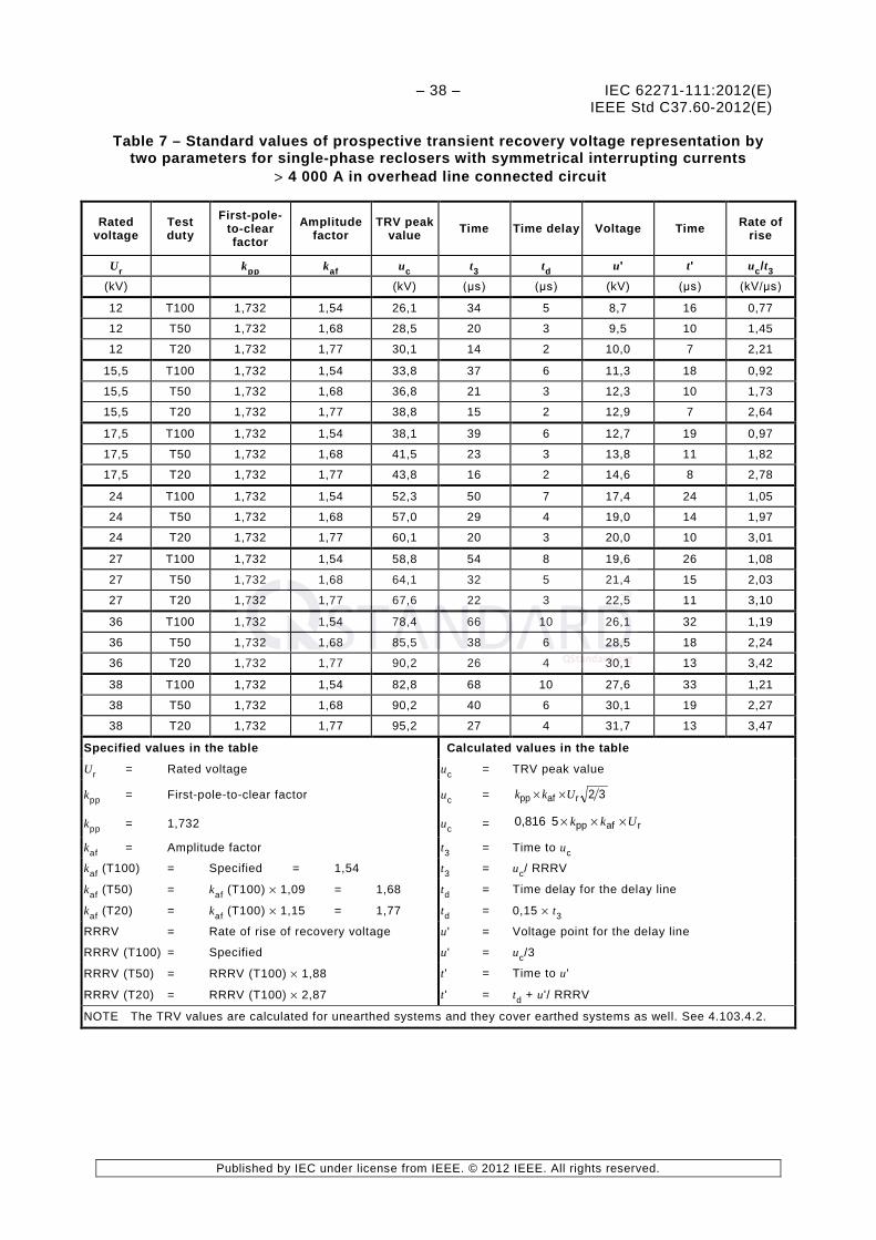
– 38 – IEC 62271-111:2012(E) IEEE Std C37.60-2012(E)
Published by IEC under license from IEEE. © 2012 IEEE. All rights reserved.
Table 7 – Standard values of prospective transient recovery voltage representation by two parameters for single-phase reclosers with symmetrical interrupting currents
> 4 000 A in overhead line connected circuit
Rated voltage
Test duty
First-pole-to-clear factor
Amplitude factor
TRV peak value Time Time delay Voltage Time Rate of
rise
Ur kpp kaf uc t3 td u' t' uc/t3 (kV) (kV) (μs) (μs) (kV) (μs) (kV/μs)
12 T100 1,732 1,54 26,1 34 5 8,7 16 0,77
12 T50 1,732 1,68 28,5 20 3 9,5 10 1,45
12 T20 1,732 1,77 30,1 14 2 10,0 7 2,21
15,5 T100 1,732 1,54 33,8 37 6 11,3 18 0,92
15,5 T50 1,732 1,68 36,8 21 3 12,3 10 1,73
15,5 T20 1,732 1,77 38,8 15 2 12,9 7 2,64
17,5 T100 1,732 1,54 38,1 39 6 12,7 19 0,97
17,5 T50 1,732 1,68 41,5 23 3 13,8 11 1,82
17,5 T20 1,732 1,77 43,8 16 2 14,6 8 2,78
24 T100 1,732 1,54 52,3 50 7 17,4 24 1,05
24 T50 1,732 1,68 57,0 29 4 19,0 14 1,97
24 T20 1,732 1,77 60,1 20 3 20,0 10 3,01
27 T100 1,732 1,54 58,8 54 8 19,6 26 1,08
27 T50 1,732 1,68 64,1 32 5 21,4 15 2,03
27 T20 1,732 1,77 67,6 22 3 22,5 11 3,10
36 T100 1,732 1,54 78,4 66 10 26,1 32 1,19
36 T50 1,732 1,68 85,5 38 6 28,5 18 2,24
36 T20 1,732 1,77 90,2 26 4 30,1 13 3,42
38 T100 1,732 1,54 82,8 68 10 27,6 33 1,21
38 T50 1,732 1,68 90,2 40 6 30,1 19 2,27
38 T20 1,732 1,77 95,2 27 4 31,7 13 3,47
Specified values in the table Calculated values in the table
Ur = Rated voltage uc = TRV peak value
kpp = First-pole-to-clear factor uc = 32rafpp Ukk ××
kpp = 1,732 uc = rafpp50,816 Ukk ×××
kaf = Amplitude factor t3 = Time to uc
kaf (T100) = Specified = 1,54 t3 = uc/ RRRV
kaf (T50) = kaf (T100) × 1,09 = 1,68 td = Time delay for the delay line
kaf (T20) = kaf (T100) × 1,15 = 1,77 td = 0,15 × t3
RRRV = Rate of rise of recovery voltage u' = Voltage point for the delay line
RRRV (T100) = Specified u' = uc/3
RRRV (T50) = RRRV (T100) × 1,88 t' = Time to u'
RRRV (T20) = RRRV (T100) × 2,87 t' = td + u'/ RRRV
NOTE The TRV values are calculated for unearthed systems and they cover earthed systems as well. See 4.103.4.2.
http://qstandard.org/

IEC 62271-111:2012(E) – 39 – IEEE Std C37.60-2012(E)
Published by IEC under license from IEEE. © 2012 IEEE. All rights reserved.
Table 8 – Standard values of prospective transient recovery voltage representation by two parameters for three-phase reclosers with symmetrical interrupting currents
> 4 000 A in cable connected systems
Rated voltage
Test duty
First-pole-to-clear factor
Amplitude factor
TRV peak value Time Time delay Voltage Time Rate of
rise
Ur kpp kaf uc t3 td u' t' uc/t3
(kV) (kV) (μs) (μs) (kV) (μs) (kV/μs)
12 T100 1,5 1,40 20,6 61 9 6,9 29 0,34
12 T50 1,5 1,53 22,5 20 3 7,5 10 1,14
12 T20 1,5 1,61 23,7 13 2 7,9 6 1,81
15,5 T100 1,5 1,40 26,6 68 10 8,9 33 0,39
15,5 T50 1,5 1,53 29,0 22 3 9,7 11 1,30
15,5 T20 1,5 1,61 30,6 15 2 10,2 7 2,07
17,5 T100 1,5 1,40 30,0 71 11 10,0 35 0,42
17,5 T50 1,5 1,53 32,8 23 4 10,9 11 1,40
17,5 T20 1,5 1,61 34,5 15 2 11,5 7 2,23
24 T100 1,5 1,40 41,2 88 13 13,7 42 0,47
24 T50 1,5 1,53 45,0 29 4 15,0 14 1,57
24 T20 1,5 1,61 47,3 19 3 15,8 9 2,50
27 T100 1,5 1,40 46,3 94 14 15,4 46 0,49
27 T50 1,5 1,53 50,6 31 5 16,9 15 1,64
27 T20 1,5 1,61 53,2 20 3 17,7 10 2,61
36 T100 1,5 1,40 61,7 109 16 20,6 52 0,57
36 T50 1,5 1,53 67,5 35 5 22,5 17 1,90
36 T20 1,5 1,61 71,0 23 4 23,7 11 3,03
38 T100 1,5 1,40 65,2 109 16 21,7 52 0,60
38 T50 1,5 1,53 71,2 36 5 23,7 17 2,00
38 T20 1,5 1,61 74,9 23 4 25,0 11 3,19
Specified values in the table Calculated values in the table
Ur = Rated voltage uc = TRV peak value
kpp = First-pole-to-clear factor uc = 32rafpp Ukk ××
kpp = 1,5 uc = rafpp50,816 Ukk ×××
kaf = Amplitude factor t3 = Time to uc
kaf (T100) = Specified = 1,4 t3 = uc/ RRRV
kaf (T50) = kaf (T100) × 1,09 = 1,53 td = Time delay for the delay line
kaf (T20) = kaf (T100) × 1,15 = 1,61 td = 0,15 × t3
RRRV = Rate of rise of recovery voltage u' = Voltage point for the delay line
RRRV (T100) = Specified u' = uc/3
RRRV (T50) = RRRV (T100) × 3,34 t' = Time to u'
RRRV (T20) = RRRV (T100) × 5,32 t' = td + u'/ RRRV
NOTE The TRV values are calculated for unearthed systems and they cover earthed systems as well. See 4.103.4.2.
http://qstandard.org/

– 40 – IEC 62271-111:2012(E) IEEE Std C37.60-2012(E)
Published by IEC under license from IEEE. © 2012 IEEE. All rights reserved.
Table 9 – Standard values of prospective transient recovery voltage representation by two parameters for single-phase reclosers with symmetrical interrupting currents
> 4 000 A in cable connected systems
Rated voltage
Test duty
First-pole-to-clear factor
Amplitude factor
TRV peak value Time Time delay Voltage Time Rate of
rise
Ur kpp kaf uc t3 td u' t' uc/t3
(kV) (kV) (μs) (μs) (kV) (μs) (kV/μs)
12 T100 1,732 1,40 23,8 70 10 7,9 34 0,34
12 T50 1,732 1,53 26,0 23 3 8,7 11 1,14
12 T20 1,732 1,61 27,3 15 2 9,1 7 1,81
15,5 T100 1,732 1,40 30,7 79 12 10,2 38 0,39
15,5 T50 1,732 1,53 33,5 26 4 11,2 12 1,30
15,5 T20 1,732 1,61 35,3 17 3 11,8 8 2,07
17,5 T100 1,732 1,40 34,6 82 12 11,5 40 0,42
17,5 T50 1,732 1,53 37,9 27 4 12,6 13 1,40
17,5 T20 1,732 1,61 39,8 18 3 13,3 9 2,23
24 T100 1,732 1,40 47,5 101 15 15,8 49 0,47
24 T50 1,732 1,53 51,9 33 5 17,3 16 1,57
24 T20 1,732 1,61 54,6 22 3 18,2 11 2,50
27 T100 1,732 1,40 53,5 109 16 17,8 53 0,49
27 T50 1,732 1,53 58,4 36 5 19,5 17 1,64
27 T20 1,732 1,61 61,5 24 4 20,5 11 2,61
36 T100 1,732 1,40 71,3 125 19 23,8 60 0,57
36 T50 1,732 1,53 77,9 41 6 26,0 20 1,90
36 T20 1,732 1,61 82,0 27 4 27,3 13 3,03
38 T100 1,732 1,40 75,2 125 19 25,1 61 0,60
38 T50 1,732 1,53 82,2 41 6 27,4 20 2,00
38 T20 1,732 1,61 86,5 27 4 28,8 13 3,19
Specified values in the table Calculated values in the table
Ur = Rated voltage uc = TRV peak value
kpp = First-pole-to-clear factor uc = 32rafpp Ukk ××
kpp = 1,732 uc = rafpp50,816 Ukk ×××
kaf = Amplitude factor t3 = Time to uc
kaf (T100) = Specified = 1,4 t3 = uc/ RRRV
kaf (T50) = kaf (T100) × 1,09 = 1,53 td = Time delay for the delay line
kaf (T20) = kaf (T100) × 1,15 = 1,61 td = 0,15 × t3
RRRV = Rate of rise of recovery voltage u' = Voltage point for the delay line
RRRV (T100) = Specified u' = uc/3
RRRV (T50) = RRRV (T100) × 3,34 t' = Time to u'
RRRV (T20) = RRRV (T100) × 5,32 t' = td + u'/ RRRV
NOTE The TRV values are calculated for unearthed systems and they cover earthed systems as well. See 4.103.4.2.
http://qstandard.org/

IEC 62271-111:2012(E) – 41 – IEEE Std C37.60-2012(E)
Published by IEC under license from IEEE. © 2012 IEEE. All rights reserved.
Table 10 – Standard values of prospective transient recovery voltage representation by two parameters for three-phase reclosers with symmetrical interrupting currents ≤ 4 000 A in both overhead and cable connected systems and three-phase fault
interrupters of all interrupting ratings in cable connected systems
Rated voltage
Test duty
First-pole-to-clear factor
Amplitude factor
TRV peak value Time Time delay Voltage Time Rate of
rise
Ur kpp kaf uc t3 td u' t' uc/t3
(kV) (kV) (μs) (μs) (kV) (μs) (kV/μs)
12 T100 1,5 1,54 22,6 117,6 18 7,5 57 0,19
12 T50 1,5 1,54 22,6 117,6 18 7,5 57 0,19
12 T20 1,5 1,54 22,6 117,6 18 7,5 57 0,19
15,5 T100 1,5 1,54 29,2 132,9 20 9,7 64 0,22
15,5 T50 1,5 1,54 29,2 132,9 20 9,7 64 0,22
15,5 T20 1,5 1,54 29,2 132,9 20 9,7 64 0,22
17,5 T100 1,5 1,54 33,0 140,5 21 11,0 68 0,24
17,5 T50 1,5 1,54 33,0 140,5 21 11,0 68 0,24
17,5 T20 1,5 1,54 33,0 140,5 21 11,0 68 0,24
24 T100 1,5 1,54 45,3 166,1 25 15,1 80 0,27
24 T50 1,5 1,54 45,3 166,1 25 15,1 80 0,27
24 T20 1,5 1,54 45,3 166,1 25 15,1 80 0,27
27 T100 1,5 1,54 50,9 178,7 27 17,0 86 0,29
27 T50 1,5 1,54 50,9 178,7 27 17,0 86 0,29
27 T20 1,5 1,54 50,9 178,7 27 17,0 86 0,29
36 T100 1,5 1,54 67,9 213,9 32 22,6 103 0,32
36 T50 1,5 1,54 67,9 213,9 32 22,6 103 0,32
36 T20 1,5 1,54 67,9 213,9 32 22,6 103 0,32
38 T100 1,5 1,54 71,7 222,2 33 23,9 107 0,32
38 T50 1,5 1,54 71,7 222,2 33 23,9 107 0,32
38 T20 1,5 1,54 71,7 222,2 33 23,9 107 0,32
Specified values in the table Calculated values in the table
Ur = Rated voltage uc = TRV peak value
kpp = First-pole-to-clear factor uc = 32rafpp Ukk ××
kpp = 1,5 uc = rafpp50,816 Ukk ×××
kaf = Amplitude factor t3 = Time to uc
kaf (T100) = Specified = 1,54 t3 = uc/ RRRV
kaf (T50) = kaf (T100) × 1,09 = 1,54 td = Time delay for the delay line
kaf (T20) = kaf (T100) × 1,15 = 1,54 td = 0,15 × t3
RRRV = Rate of rise of recovery voltage u' = Voltage point for the delay line
RRRV (T100) = Specified u' = uc/3
RRRV (T50) = RRRV (T100) t' = Time to u'
RRRV (T20) = RRRV (T100) t' = td + u'/ RRRV
NOTE The TRV values are calculated for unearthed systems and they cover earthed systems as well. See 4.103.4.2.
http://qstandard.org/

– 42 – IEC 62271-111:2012(E) IEEE Std C37.60-2012(E)
Published by IEC under license from IEEE. © 2012 IEEE. All rights reserved.
Table 11 – Standard values of prospective transient recovery voltage representation by two parameters for single-phase reclosers with symmetrical interrupting currents ≤ 4 000 A in both overhead and cable connected systems and single-phase fault
interrupters of all interrupting ratings in cable connected systems
Rated voltage
Test duty
First-pole-to-clear factor
Amplitude factor
TRV peak value Time Time delay Voltage Time Rate of
rise
Ur kpp kaf uc t3 td u' t' uc/t3
(kV) (kV) (μs) (μs) (kV) (μs) (kV/μs)
12 T100 1,732 1,54 26,1 135,8 20 8,7 66 0,19
12 T50 1,732 1,54 26,1 135,8 20 8,7 66 0,19
12 T20 1,732 1,54 26,1 135,8 20 8,7 66 0,19
15,5 T100 1,732 1,54 33,8 153,4 23 11,3 74 0,22
15,5 T50 1,732 1,54 33,8 153,4 23 11,3 74 0,22
15,5 T20 1,732 1,54 33,8 153,4 23 11,3 74 0,22
17,5 T100 1,732 1,54 38,1 162,2 24 12,7 78 0,24
17,5 T50 1,732 1,54 38,1 162,2 24 12,7 78 0,24
17,5 T20 1,732 1,54 38,1 162,2 24 12,7 78 0,24
24 T100 1,732 1,54 52,3 191,8 29 17,4 93 0,27
24 T50 1,732 1,54 52,3 191,8 29 17,4 93 0,27
24 T20 1,732 1,54 52,3 191,8 29 17,4 93 0,27
27 T100 1,732 1,54 58,8 206,3 31 19,6 100 0,29
27 T50 1,732 1,54 58,8 206,3 31 19,6 100 0,29
27 T20 1,732 1,54 58,8 206,3 31 19,6 100 0,29
36 T100 1,732 1,54 78,4 246,9 37 26,1 119 0,32
36 T50 1,732 1,54 78,4 246,9 37 26,1 119 0,32
36 T20 1,732 1,54 78,4 246,9 37 26,1 119 0,32
38 T100 1,732 1,54 82,8 256,6 38 27,6 124 0,32
38 T50 1,732 1,54 82,8 256,6 38 27,6 124 0,32
38 T20 1,732 1,54 82,8 256,6 38 27,6 124 0,32
Specified values in the table Calculated values in the table
Ur = Rated voltage uc = TRV peak value
kpp = First-pole-to-clear factor uc = 32rafpp Ukk ××
kpp = 1,732 uc = rafpp50,816 Ukk ×××
kaf = Amplitude factor t3 = Time to uc
kaf (T100) = Specified = 1,54 t3 = uc/ RRRV
kaf (T50) = kaf (T100) × 1,09 = 1,54 td = Time delay for the delay line
kaf (T20) = kaf (T100) × 1,15 = 1,54 td = 0,15 × t3
RRRV = Rate of rise of recovery voltage u' = Voltage point for the delay line
RRRV (T100) = Specified u' = uc/3
RRRV (T50) = RRRV (T100) t' = Time to u'
RRRV (T20) = RRRV (T100) t' = td + u'/ RRRV
NOTE The TRV values are calculated for unearthed systems and they cover earthed systems as well. See 4.103.4.2.
http://qstandard.org/

IEC 62271-111:2012(E) – 43 – IEEE Std C37.60-2012(E)
Published by IEC under license from IEEE. © 2012 IEEE. All rights reserved.
4.104 Rated symmetrical making current (short-circuit making current)
Reclosers and fault interrupters shall be capable of making, at any applied voltage, up to and including that corresponding to their rated voltage, any current up to and including their rated symmetrical making current.
The rated symmetrical making current shall be the same value as the rated symmetrical interrupting current, with maximum asymmetry corresponding to the X/R ratio in column (9) of Table 12.
http://qstandard.org/

Pub
lishe
d by
IEC
und
er li
cens
e fr
om IE
EE
. © 2
012
IEE
E. A
ll rig
hts
rese
rved
.
IEC 62271-111:2012(E) – 44 – IEEE Std C37.60-2012(E)
Tabl
e 12
– P
erfo
rman
ce c
hara
cter
isti
cs –
Sta
ndar
d op
erat
ing
duty
S
tand
ard
oper
atin
g du
ty a (
NO
TE 1
)
T20
T50
T100
Per
cent
of i
nter
rupt
ing
rati
ng
15 –
20
d
45 –
55
90 –
100
Line
(N
OTE
2)
Equ
ipm
ent
type
Sym
met
rica
l in
terr
upti
ng
rati
ng
(kA
)
X/R
c
(NO
TE 3
)
Num
ber
of
unit
oper
atio
ns
X/R
c
(NO
TE 3
)
Num
ber
of
unit
oper
atio
ns
X/R
c
(NO
TE 3
)
Num
ber
of
unit
oper
atio
ns
Tota
l num
ber
of u
nit
oper
atio
ns
(1)
(2)
(3)
(4)
(5)
(6)
(7)
(8)
(9)
(10)
(1
1)
1 --
C
utou
t m
ount
ed
recl
oser
A
ll 2
32
4 24
8
12
68
2 --
R
eclo
sers
-/FI
≤2
,0
2 52
5
68
10
18
138
3 --
R
eclo
sers
-/FI
>2
,0 a
nd <
8,0
3 48
7
60
14
16
124
4 --
R
eclo
sers
-/FI
≥8
,0
4 44
8
56
b 16
11
6 a
Thes
e ar
e pe
rfor
man
ce c
hara
cter
istic
s sp
ecifi
ed a
s te
st r
equi
rem
ents
in th
is s
tand
ard.
b
Ref
. C
ol.
9: X
/R =
14
for
50 H
z an
d 17
for
60
Hz
for
a st
anda
rd t
ime
cons
tant
of
45 m
s, A
d.c
. tim
e co
nsta
nt u
p to
120
ms
may
occ
ur i
n so
me
appl
icat
ions
. Th
ese
appl
icat
ions
are
out
side
the
sco
pe o
f th
is s
tand
ard
and
shal
l be
dis
cuss
ed w
ith t
he m
anuf
actu
rer.
Add
ition
al i
nfor
mat
ion
on t
his
subj
ect
can
be f
ound
in
IEC
622
71-
100.
c
For
test
pur
pose
s X/
R va
lues
are
min
imum
val
ues.
Ref
er to
4.1
02 a
nd 6
.103
.2.
d Fo
r si
mul
atio
n of
mul
ti-ea
rthe
d w
ye c
ircui
ts, 2
5 %
– 3
0 %
of t
he o
pera
tions
in c
olum
n (6
) ar
e to
be
perf
orm
ed w
ith b
oth
load
and
sou
rce
eart
hed.
See
6.1
03.1
.3.
NO
TE 1
Th
e st
anda
rd o
pera
ting
duty
for
lin
es 2
, 3,
and
4 r
epre
sent
the
hal
f-lif
e as
mea
sure
d by
con
tact
ero
sion
. R
efer
to
man
ufac
ture
r’s m
etho
ds f
or d
eter
min
ing
perm
issi
ble
cont
act e
rosi
on.
NO
TE 2
C
olum
n (2
) is
not
use
d in
this
tabl
e; it
is in
clud
ed to
pro
vide
con
sist
ency
with
Tab
le I.
3 an
d Ta
ble
I.4
NO
TE 3
D
ue to
lim
itatio
ns o
f so
me
labo
rato
ries,
hig
her
X/R
valu
es m
ay b
e re
quire
d, e
spec
ially
at t
he h
ighe
r in
terr
uptin
g ra
tings
.
http://qstandard.org/

IEC 62271-111:2012(E) – 45 – IEEE Std C37.60-2012(E)
Published by IEC under license from IEEE. © 2012 IEEE. All rights reserved.
4.105 Rated operating sequence
The rated characteristics of the recloser and fault interrupter are referred to the rated operating sequence. The preferred rated operating sequences shall be:
a) for automatic circuit reclosers: O - t - CO - t' - CO - t" – CO,
b) for fault interrupters: CO.
Other sequences may be used
where O represents an open operation; CO represents a closing operation followed by an opening operation with a time delay
controlled by the automatic control of the device.
The preferred values for the reclosing intervals are: t = 0,5 s, t' = 2 s and t" = 5 s representing the fastest rapid reclosing interval capability of the device controlled by its automatic control. Other reclosing intervals may be used.
NOTE See Annex I for rated operating sequence for oil interrupting reclosers.
The operating sequence and reclosing intervals represent the minimum required capability of the device and shall be demonstrated in the standard operating duty test specified in 6.103.4 and 6.103.5. Other operating sequences, delays and reclosing intervals may be available for selection by the user.
4.106 Rated line and cable charging interrupting currents
The preferred line and cable charging interrupting current ratings for reclosers/FIs are as given in Table 13.
Table 13 – Preferred line and cable charging interrupting current ratings
Rated maximum voltage
kV
Maximum current
A (r.m.s.)
Line charging Cable Charging
12 2 10
15,5 2 10
24 5 25
27 5 25
36 5 40
38 5 40
5 Design and construction
Requirements for liquids in switchgear and controlgear 5.1
Subclause 5.1 of IEEE Std C37.100.1-2007 or IEC 62271-1:2007 is applicable.
Liquid level 5.1.1
Subclause 5.1.1 of IEEE Std C37.100.1-2007 or IEC 62271-1:2007 is applicable.
http://qstandard.org/

– 46 – IEC 62271-111:2012(E) IEEE Std C37.60-2012(E)
Published by IEC under license from IEEE. © 2012 IEEE. All rights reserved.
Liquid quality 5.1.2
Subclause 5.1.2 of IEEE Std C37.100.1-2007 or IEC 62271-1:2007 is applicable.
Oil sampling provision (submersible reclosers/FIs) 5.1.3
When oil is used as the insulating medium, provision shall be made to obtain a bottom oil sample.
Requirements for gases in switchgear and controlgear 5.2
Subclause 5.2 of IEEE Std C37.100.1-2007 or IEC 62271-1:2007 is applicable.
Earthing of switchgear and controlgear 5.3
NOTE The terms “ground” and “grounding” in IEEE are equivalent to the IEC terms “earth” and “earthing”.
A recloser/FI with a metal housing shall have provisions for the connection of an earth (ground) lead.
The earth (ground) connector shall accommodate an earth (ground) conductor of a size adequate to conduct the rated symmetrical interrupting current of the recloser/FI for the duration of at least 1,5tk without damage to the conductor or connector. The peak current of the first major loop shall be as defined in 4.6 of IEEE Std C37.100.1-2007 or IEC 62271-1:2007.
A recloser/FI control housing that may be mounted separately from the recloser/FI or that contains control elements that rely on solid earthing (grounding) for surge immunity shall also have provisions for the connection of an earth (ground) lead.
Pad mounted, dry vault and submersible reclosers/FIs shall have an additional earthing (grounding) connection for each three-phase set of cable entrances.
Auxiliary and control equipment 5.4
Subclause 5.4 of IEEE Std C37.100.1-2007 and IEC 62271-1:2007 are not applicable. 6
Dependent power operation 5.5
Subclause 5.5 of IEEE Std C37.100.1-2007 or IEC 62271-1:2007 is applicable.
Stored energy operation 5.6
Subclause 5.6 of IEEE Std C37.100.1-2007 and IEC 62271-1:2007 are not applicable.
NOTE 1 When indicators are used on stored energy operating mechanisms, guidance on the colors or symbols should be taken from IEC 60073 [38] and IEC 60417 [39].
NOTE 2 Customer (user) preferences or local codes for indicators should be specified by the user.
Independent manual operation or power operation (independent unlatched 5.7operation)
Subclause 5.7 of IEEE Std C37.100.1-2007 or IEC 62271-1:2007 is applicable with the following addition.
————————— 6 The statement that “Sublause x.x of IEEE Std C37.100.1:2007 and IEC 62271-1:2007 are not applicable”
without further qualification means that no requirements exist for this topic within this standard.
http://qstandard.org/

IEC 62271-111:2012(E) – 47 – IEEE Std C37.60-2012(E)
Published by IEC under license from IEEE. © 2012 IEEE. All rights reserved.
Reclosers/FIs shall be provided with a manual operating lever to open the recloser/FI. The operating lever shall be suitable for operation with a hot line stick.
NOTE Some applications may require that the operating lever on a submersible recloser/FI be located such that one person standing on the surface can operate it without standing directly over the recloser/FI. These special applications should be specified by the user.
Operation of releases 5.8
The operation limits of releases shall be as specified in 5.8.1, 5.8.2, 5.8.3 and 5.8.4.
Shunt closing release 5.8.1
A shunt closing release shall operate correctly within the minimum and maximum operating voltage range specified in 4.8.
Shunt opening release 5.8.2
If shunt releases are supplied, a shunt opening release shall operate correctly under all operating conditions of the switching device up to its rated symmetrical interrupting current.
a) If the auxiliary control is rated in accordance with IEEE Std C37.100.1, the opening release shall operate correctly within the minimum and maximum operating voltage range specified in 4.8.
b) If the auxiliary control is rated in accordance with IEC 62271-1, the opening release shall operate correctly between 70 % in the case of d.c. or 85 % in the case of a.c. and 110 % of the rated supply voltage of the opening device (refer to 4.8).
Capacitor operation of shunt releases 5.8.3
When, for stored energy operation of a shunt release, a rectifier-capacitor combination is provided as an integral part of the switching device, the charge of the capacitors to be derived from the voltage of the main circuit or the auxiliary supply, the capacitors shall retain a charge sufficient for satisfactory operation of the release 5 s after the voltage supply has been disconnected from the terminals of the combination and replaced by a short-circuiting link.
The voltages of the main circuit before disconnection shall be taken as the lowest voltage of the system associated with the rated voltage of the switching device.
Under-voltage release 5.8.4
If under-voltage releases are supplied, an under-voltage release shall operate to open the switching device when the voltage at the terminals of the release falls below 35 % of its rated voltage, even if the fall is slow and gradual.
On the other hand, it shall not operate the switching device when the voltage at its terminals exceeds 70 % of its rated supply voltage.
The closing of the switching device shall be possible when the values of the voltage at the terminals of the release are equal to or higher than 85 % of its rated voltage. Its closing shall be impossible when the voltage at the terminals is lower than 35 % of its rated supply voltage.
Low- and high- pressure interlocking devices and monitoring devices 5.9
Subclause 5.9 of IEEE Std C37.100.1-2007 or IEC 62271-1:2007 is applicable.
NOTE Low and high pressure interlocking devices are generally applicable to reclosers/FIs using compressed air or closed pressure SF6 as insulating or interrupting medium. For sealed-pressure systems, these devices are not required.
http://qstandard.org/

– 48 – IEC 62271-111:2012(E) IEEE Std C37.60-2012(E)
Published by IEC under license from IEEE. © 2012 IEEE. All rights reserved.
Nameplates 5.10
Subclause 5.10 of IEEE Std C37.100.1-2007 or IEC 62271-1:2007 is applicable, with the following additions.
The nameplates for recloser/FI shall be marked in accordance with Table 14.
NOTE It should be stated whether pressures (or densities) are absolute or relative values.
If the switchgear consists of several poles with independent operating mechanisms, each pole shall be provided with a nameplate. This requirement does not apply if all of the pole mechanisms are mounted to a common structure.
For submersible reclosers/FIs, a nameplate of stainless steel or other corrosion resistant material shall be provided. The nameplate shall be securely attached to the top of the tank by means of stainless steel screws, rivets, or other corrosion resistant fasteners. All letters, schematics and numbers shall be permanently stamped, embossed or engraved on the nameplate.
http://qstandard.org/

IEC 62271-111:2012(E) – 49 – IEEE Std C37.60-2012(E)
Published by IEC under license from IEEE. © 2012 IEEE. All rights reserved.
Table 14 – Nameplate markings
Abbreviation (NOTE 1) Unit
Condition: Marking only
required if
Marking requirement
(1) (2) (3) (4) (5)
Manufacturer's name or trademark X
Manufacturer’s type designation X
Equipment type a X
Rated maximum voltage V or Ur kV X
Rated lightning impulse withstand voltage Up kV X
Rated power-frequency fr Hz
Rating is not applicable at both 50 Hz and 60 Hz
y
Rated continuous (normal) current Ir A X
Rated duration of short circuit tk s Different from 0,5 s y
Rated symmetrical interrupting current (rated short-circuit breaking current)
Isc A or kA X
Rated minimum tripping current I>min A
Non-adjustable series-trip- reclosers/FIs
y
Rated operating sequence
Different from the preferred sequences (see 4.105)
y
Rated ice breaking capability
Greater than 1 mm and if type testing is required, see 6.110
(X) y
Type and quantity (volume of liquid or mass of gas) of insulating material
l (gal) or kg (lbs)
(NOTE 2) Contains fluid or gas y
Mass (including oil for oil-filled devices) kg (lbs)
(NOTE 2) X
Serial number and date of manufacture
X
In Column (5): X = the marking of these values is mandatory; blanks indicate the value zero.
(X) = the marking of these values is optional.
y = the marking of these values to the conditions in column (4).
a Equipment type: the nameplate shall also contain the word(s) “recloser”, “cutout mounted recloser”, or “fault interrupter” in accordance with its operating sequence capability as given in 4.105.
NOTE 1 The abbreviation in column (2) may be used instead of the term in column (1). When the term in column (1) is used, the word “rated“ is not required.
NOTE 2 SI metric units are preferred; alternate units in parentheses () are acceptable alternates.
Interlocking devices 5.11
Subclause 5.11 of IEEE Std C37.100.1-2007 and IEC 62271-1:2007 are not applicable.
http://qstandard.org/

– 50 – IEC 62271-111:2012(E) IEEE Std C37.60-2012(E)
Published by IEC under license from IEEE. © 2012 IEEE. All rights reserved.
Position indication 5.12
Subclause 5.12 of IEEE Std C37.100.1-2007 or IEC 62271-1:2007 is applicable with the following additions:
For pad mounted, dry vault or submersible reclosers/FIs viewing of the position indicator may require opening of the pad-mounted or underground enclosure.
In the absence of user specifications, the preferred colors to indicate an open or closed position are red to signify closed and green to signify open.
Degrees of protection provided by enclosures 5.13
Subclause 5.13 and all of its subclauses of IEEE Std C37.100.1-2007 and IEC 62271-1:2007 are not applicable to reclosers/FIs designed to be mounted on an overhead structure (e.g. pole or frame).
Subclause 5.13 of IEEE Std C37.100.1-2007 or IEC 62271-1:2007 is applicable to pad mounted reclosers/FIs with the additions in 5.13.1, 5.13.2, 5.13.3 and 5.13.101.
Protection of persons against access to hazardous parts and protection of the 5.13.1equipment against ingress of solid foreign objects (IP coding)
Pad mounted reclosers/FIs shall conform to the degree of protection level IP4X or higher. Conformance to IEEE Std C57.12.28 shall constitute fulfillment of this requirement.
NOTE The IP45 protection level specifies a probe >1 mm in diameter which is slightly smaller than the number 14 gauge wire (1,63 mm) specified in IEEE Std C57.12.28. Refer to IEC 60529 [17].
Protection against ingress of water (IP coding) 5.13.2
Reclosers/FIs shall conform to the degree of protection level IPX5 or higher. Conformance to IEEE Std C57.12.28 shall constitute fulfillment of this requirement.
Protection of equipment against mechanical impact under normal service 5.13.3conditions (IK coding)
Subclause 5.13.3 of IEC 62271-1:2007 does not apply.
Enclosure design and coating system requirements 5.13.101
The requirements of IEEE Std C57.12.28 are applicable.
Alternative IEC standards for the protection of enclosures are given in Annex M. These standards may be used by agreement between the user and the manufacturer.
Creepage distances for outdoor insulators 5.14
Subclause 5.14 of IEEE Std C37.100.1-2007 or IEC 62271-1:2007 is applicable with the following addition:
The minimum creepage distances apply to glass and ceramic insulators. Values for other materials are under consideration.
http://qstandard.org/

IEC 62271-111:2012(E) – 51 – IEEE Std C37.60-2012(E)
Published by IEC under license from IEEE. © 2012 IEEE. All rights reserved.
Gas and vacuum tightness 5.15
The following specifications apply to all reclosers/FI that use vacuum or gas, other than ambient air, as an insulating, combined insulating and interrupting, or operating medium. IEEE Std C37.100.1-2007, Annex G and IEC 62271-1:2007, Annex E give some information, examples and guidance for tightness.
Controlled pressure systems for gas 5.15.1
The tightness of controlled pressure systems for gas is specified by the number of replenishments per day (N) or by the pressure drop per day (Dp). The permissible values shall be given by the manufacturer.
Closed pressure systems for gas 5.15.2
The tightness characteristic of a closed pressure system and the time between replenishment under normal service condition shall be stated by the manufacturer and shall be consistent with a minimum maintenance and inspection philosophy.
The tightness of closed pressure systems for gas is specified by the relative leakage rate Frel of each compartment; standardized values are:
– for SF6 and SF6 mixtures, the standardized values are 0,5 % and 1 % per year; – for other gases, the standardized values are 0,5 %, 1 % and 3 % per year.
The value for the time between replenishment shall be at least 10 years for SF6 systems and for other gases should be consistent with the tightness values.
The possible leakages between subassemblies having different pressures shall also be taken into account. In the particular case of maintenance in a compartment when adjacent compartments contain gas under pressure, the permissible gas leakage rate across partitions should also be stated by the manufacturer, and the time between replenishments shall be not less than one month.
Means shall be provided to enable gas systems to be safely replenished while the equipment is in service.
Sealed pressure systems 5.15.3
The tightness of sealed pressure systems is specified by their expected operating life.
The expected operating life with regard to leakage performance shall be specified by the manufacturer. Preferred values are 20 years, 30 years and 40 years.
NOTE To fulfill the expected operating life requirement, the leakage rate for SF6 systems is considered to be 0,1 % per year.
Design and withstand 5.15.101
Reclosers/FI’s with operating pressure greater than one atmosphere shall adhere to the requirements of local jurisdictional codes as applicable.
Leak rate 5.15.102
The maximum permissible gas leak rate shall not exceed the rate corresponding to a minimum 10-year replenishment period.
http://qstandard.org/

– 52 – IEC 62271-111:2012(E) IEEE Std C37.60-2012(E)
Published by IEC under license from IEEE. © 2012 IEEE. All rights reserved.
Liquid tightness 5.16
Subclause 5.16 of IEEE Std C37.100.1-2007 or IEC 62271-1:2007 is applicable with the following addition:
Tank construction for liquid filled or non-pressurized devices shall be such that leaks will not occur and the recloser/FI will remain mechanically operable at the maximum operating pressure generated by the normal operation of the recloser/FI (for example, temperature rise, load interrupting and fault closing).
Fire hazard (flammability) 5.17
Subclause 5.17 of IEEE Std C37.100.1-2007 or IEC 62271-1:2007 is not applicable.
Electromagnetic compatibility (EMC) 5.18
The secondary system shall be able to withstand electromagnetic disturbances stated in 6.111 without damage or malfunction.
X-ray emission 5.19
Subclause 5.19 of IEEE Std C37.100.1-2007 or IEC 62271-1:2007 is applicable.
Tank construction: submersible or dry vault reclosers/FIs 5.101
Tank material and finish 5.101.1
The tank and all appurtenances shall be made of corrosion resistant material or provided with an impact and corrosion resistant finish and shall also be suitable for storage in uncovered areas.
Water entrapment 5.101.2
External parts of the tank or accessories shall not trap or hold water.
Tank support 5.101.3
Tank support shall provide firm, stable support and shall include provision for anchoring the tank.
Lifting lugs 5.101.4
Attachment points for lifting the recloser/FI shall be provided to permit installation in accordance with the manufacturer’s instructions. They shall be designed and located on the tank to avoid interference between lifting slings and any attachments (bushings, operating handles, etc), and to avoid scratching or marring the tank finish during handling.
Counters 5.102
An operations counter shall be provided to indicate the total number of unit operations of automatic reclosers. The counter shall be visible with the recloser in service. This feature is not required for fault interrupters.
Conductor terminal sizes 5.103
For connection of bare conductors, terminals shall accommodate conductors of a size adequate to conduct the rated continuous (normal) current of the recloser/FI without exceeding the appropriate temperature rise shown in 4.4.2.
http://qstandard.org/

IEC 62271-111:2012(E) – 53 – IEEE Std C37.60-2012(E)
Published by IEC under license from IEEE. © 2012 IEEE. All rights reserved.
NOTE For reclosers/FIs fitted with cable terminations, bushings should accommodate cable terminations in accordance with the IEEE Std 386-1995 [7] or IEC 60502 series [18] unless otherwise specified by the user.
Stored mechanism charge indicator 5.104
When indicators are used on stored energy operating mechanisms, the following colors are preferred subject to any local codes or indicia requirements:
a) yellow background with CHARGED in black letters for charged mechanisms; b) white background with DISCHARGED in black letters for discharged mechanisms.
As an alternative, red letters on a white background for both indicators may be used.
6 Type tests
NOTE The term “design test” in IEEE is equivalent to the IEC term “type test”.
Clause 6 of IEEE Std C37.100.1-2007 or IEC 62271-1:2007 is applicable with the following addition:
Reclosers/FIs shall be capable of meeting the type tests described in 6.2 through 6.11 inclusive and 6.101 through 6.112 inclusive and as applicable. Once made, the type tests need not be repeated unless the design is changed so as to modify the performance characteristics of the recloser/FI.
Refer to Annex E for tolerances applied to test values.
General 6.1
The type tests are for the purpose of proving the ratings and characteristics of reclosers/FI’s, their controls, operating devices and auxiliary equipment.
Grouping of tests 6.1.1
Subclause 6.1 of IEEE Std C37.100.1-2007 or subclause 6.1.1 of IEC 62271-1:2007 is applicable with the following addition and modification.
An example of grouping is shown in Table 15. Table 15 replaces Table 8 of IEEE Std C37.100.1-2007 and IEC 62271-1:2007.
Reconditioning is not permitted during any individual type test. The complete standard operating duty test specified in 6.103 is considered as one type test.
http://qstandard.org/

– 54 – IEC 62271-111:2012(E) IEEE Std C37.60-2012(E)
Published by IEC under license from IEEE. © 2012 IEEE. All rights reserved.
Table 15 – Example of grouping
Group Type tests Subclause
1
Dielectric tests on main circuits Partial discharge tests Surge current tests (where applicable) Control electronic elements surge withstand capability tests Ice loading tests (where applicable)
6.2 6.106 6.107 6.111 6.110
2 Measurement of resistance of the main current path Temperature rise tests Mechanical tests
6.4 6.5
6.109
3
Short-time withstand current and peak withstand current tests Critical current Line charging and cable charging current tests Making current tests Rated symmetrical interruption test (standard operation duty)
6.6 6.104 6.101 6.102 6.103
4
Tests to verify the degrees of protection of enclosures Tightness tests (where applicable) Minimum tripping current tests Time-current tests
6.7 6.8
6.105 6.108
Information for identification of specimens 6.1.2
Subclause 6.1.1 of IEEE Std C37.100.1-2007 or subclause 6.1.2 of IEC 62271-1:2007 is applicable with the following addition:
The definition of an automatic circuit recloser includes its automatic control. Manufacturer shall include in the information provided to the testing laboratory sufficient information to identify the control used in the design tests. Where appropriate, this information shall include model number, serial number, firmware revision, software revision and other appropriate control software information.
The definition of a cutout mounted recloser includes a fuse type mounting or support. This mounting or support is integral to the dielectric capability of the device. Manufacturer shall include in the information provided to the testing laboratory sufficient information to identify the mounting or support used in the design tests. Where appropriate, this information shall include make, model number and rating.
Information to be included in type-test reports 6.1.3
Subclause 6.1.2 of IEEE Std C37.100.1-2007 or subclause 6.1.3 of IEC 62271-1:2007 is applicable with the following addition.
The definition of an automatic circuit recloser includes its automatic control. The control shall be considered an essential part of the switchgear in the test report including its model number, serial number, firmware revision, software revision and other appropriate control schemes.
The definition of a cutout mounted recloser includes a fuse type mounting or support. This mounting or support shall be considered an essential part of the switchgear and noted in the test report including its make, model number and rating.
A cutout mounted recloser may require the temporary attachment of an auxiliary device to perform the related switching functions of a recloser. If such a device is required, it shall be
http://qstandard.org/

IEC 62271-111:2012(E) – 55 – IEEE Std C37.60-2012(E)
Published by IEC under license from IEEE. © 2012 IEEE. All rights reserved.
considered an essential part of the switchgear and noted in the test report including its make, model number and rating
Test conditions 6.1.101
6.1.101.1 Condition of device to be tested
The recloser/FI shall be new and in good condition.
6.1.101.2 Mounting of device
The recloser/FI shall be mounted in a manner closely approximating the normal service conditions for which it is designed. If the recloser/FI normally requires control apparatus, the control apparatus shall be connected during the tests observing the following minimum requirements:
a) the control shall be mounted on the recloser as intended by the manufacturer’s design or positioned within 2 m of the recloser phase terminals under test;
b) the recloser shall be connected to the control apparatus with the manufacturer’s approved cable whose length shall be the maximum allowed by the manufacturer except that it need not exceed 6 m;
c) the control shall be placed in the same room as the recloser/FI without any additional shielding except that which is provided by the manufacturer for normal service;
d) the connections to the terminals of the switchgear shall be arranged in such a way as to avoid unrealistic stressing of the terminals. The distance between the terminals and the nearest supports of the conductors on both sides of the switchgear shall be in accordance with the instructions of the manufacturer;
e) a cutout mounted recloser may require the temporary attachment of an auxiliary device to perform the related switching functions of a recloser. If such a device is required, it need not be mounted except for those tests requiring its use;
f) the test arrangement shall be noted in the test report.
If the control apparatus is intended by the manufacturer to always be integrally mounted to or within the recloser structure it shall be considered in compliance with a) and b) above with a zero length control cable.
6.1.101.3 Earthing (grounding) of device
All parts of the recloser, including control apparatus where used, shall be earthed by a lead attached to the earth terminal and other parts to be earthed, in a manner not to decrease the withstand voltage.
6.1.101.4 Power-frequency
The frequency of the power supply voltage shall be the rated value ±5 %, except that tests at 50 Hz or 60 Hz may be used to qualify for both rated power-frequencies.
NOTE Refer to IEC/TR 62271-306 [19] for additional information about the applicability of tests at different frequencies.
6.1.101.5 Control voltage
The recloser/FI shall perform satisfactorily over the full range of control voltages specified in 4.8.
http://qstandard.org/

– 56 – IEC 62271-111:2012(E) IEEE Std C37.60-2012(E)
Published by IEC under license from IEEE. © 2012 IEEE. All rights reserved.
Dielectric tests 6.2
Subclause 6.2 of IEEE Std C37.100.1-2007 or IEC 62271-1:2007 is applicable with the following additions and modifications:
The tests shall be performed with the test voltages given in Table 2 or Table 3.
Rated insulation levels for cutout mounted reclosers are based in part on the rating of the fuse support or base identified by the manufacturer in 6.1.1 and 6.1.2. See 6.2.5.2 for special test conditions for the cutout mounted recloser.
Reclosers/FIs shall be capable of withstanding, without damage to the recloser/FI and associated control apparatus, if any, the test voltages of 6.2 when tested in accordance with 6.1.
Insulation tests of reclosers/FIs shall be performed only when the recloser/FI is completely isolated from all system voltages. Refer to Clause 101 for field-testing.
Ambient air conditions during tests 6.2.1
Subclause 6.2.1 of IEEE Std C37.100.1-2007 or IEC 62271-1:2007 is applicable.
Wet test procedure 6.2.2
Subclause 6.2.2 of IEEE Std C37.100.1-2007 or IEC 62271-1:2007 is applicable with the additions given in 6.2.6.1.
Conditions of switchgear and controlgear during dielectric tests 6.2.3
Subclause 6.2.3 of IEEE Std C37.100.1-2007 or IEC 62271-1:2007 is applicable with the following additions:
a) on overhead reclosers electrical connections shall be made by means of bare wire, inserted in each terminal. These bare wires shall project in such a manner as not to decrease the withstand value. Any necessary bends may be made at the terminals. The test lead connections shall be made to the wires projecting from the terminals. Terminals shall be representative of those used in service;
b) on pad mounted, submersible and dry vault reclosers/FIs connections shall be made through a cable termination similar to that for which the recloser/FI was designed. If terminations capable of meeting the specified dielectric voltage are not available, other terminations (bushing or connectors, or both) may be substituted for the purpose of performing these tests.
WARNING
When performing tests involving open contacts in vacuum, adequate precautions such as shielding or distance should be used to protect test personnel against the possible occurrences of higher X-radiation due, for example, to incorrect contact spacing, or to the application of voltages in excess of those specified. For example, maintaining a distance of 2 m to 3 m between the recloser/FI and all test personnel is a typical basic precaution to reduce the risk of excess X-radiation exposure. Further discussion of shielding, adequate distances and personnel exposure limits are found in ANSI C37.85 [20], American National Standard for Switchgear Alternating-Current High-Voltage Power Vacuum Interrupters – Safety Requirements for X-Radiation Limits.
http://qstandard.org/

IEC 62271-111:2012(E) – 57 – IEEE Std C37.60-2012(E)
Published by IEC under license from IEEE. © 2012 IEEE. All rights reserved.
Criteria to pass the test 6.2.4
Subclause 6.2.4 of IEEE Std C37.100.1-2007 or IEC 62271-1:2007 is applicable with the following addition:
Refer also to IEEE Std C37.100.1-2007, clause 6.2.6.2 or IEC 62271-1:2007:2007, 6.2.4 Note 3.
Application of the test voltage and test conditions 6.2.5
Subclause 6.2.5 of IEEE Std C37.100.1-2007 or IEC 62271-1:2007 is applicable.
6.2.5.1 General case
Subclause 6.2.5.1 of IEEE Std C37.100.1-2007 or IEC 62271-1:2007 is applicable with the following addition:
Single-phase reclosers/FIs shall be tested for conditions 1, 4 and 7 of Table 9 of IEEE Std C37.100.1-2007 or IEC 62271-1:2007. The connections of the terminals for phases B and C are not applicable.
6.2.5.2 Special case
The open position tests for cutout mounted reclosers are given for the device in the “dropped-out” position.
If the operating sequence allows the device to rest with an open interrupter gap and a closed disconnector gap, both the isolation gap alone and the interrupter gap alone shall be tested for the open position test cases.
Tests of switchgear and controlgear of Ur ≤ 245 kV 6.2.6
Subclause 6.2.6 of IEEE Std C37.100.1-2007 or IEC 62271-1:2007 is applicable with the following modifications:
The tests shall be performed with the test voltages given in Table 2 or Table 3.
NOTE The scope of this standard is limited to the voltage range of 1 000 V up to 38 000 V.
6.2.6.1 Power-frequency voltage tests
Subclause 6.2.6.1 of IEEE Std C37.100.1-2007 or IEC 62271-1:2007 is applicable with the following addition:
a) IEEE values of rated maximum voltage, column (2) of Table 2 and Table 3: Power-frequency withstand test voltages shall be applied in accordance with IEEE Std 4, with a peak value equal to 1,414 times the rated power-frequency withstand dry and wet test values given in Columns (5) and (6) of Table 2 and Table 3. The test duration shall be 60 s for the dry test.
The preferred method for wet tests shall be the “conventional procedure-practice in the US” of IEEE Std 4 with a test duration of 10 s. The “standard test procedure” of IEEE Std 4 is allowed as an alternate. Wet tests shall not apply to reclosers/FIs utilizing submersible cables and terminations.
NOTE Future designs should standardize the wet test procedure by adopting the “standard test procedure” as defined in IEEE Std 4.
b) IEC Values of rated maximum voltage, Column (3) Table 2 and Table 3.
http://qstandard.org/

– 58 – IEC 62271-111:2012(E) IEEE Std C37.60-2012(E)
Published by IEC under license from IEEE. © 2012 IEEE. All rights reserved.
6.2.6.2 Lightning impulse voltage tests
Subclause 6.2.6.2 of IEEE Std C37.100.1-2007 or IEC 62271-1:2007 is applicable with the following addition to IEC 62271-1:
The voltage levels shall be equal to or greater than those that are specified.
6.2.6.101 DC withstand test voltage
On reclosers/FIs using pad mounted, dry vault, and submersible cable connectors, a d.c. withstand test shall be performed in addition to the power-frequency withstand test in 6.2.6.1 above. When used, the test voltage applied shall be the value given in column (7) of Table 3. DC or very low frequency test voltages are used on cables that still may be connected to the switchgear. This design test is included to verify that the switchgear can also withstand the same test voltage.
Refer to Clause 101 for a discussion on field tests.
The d.c. power source for the d.c. withstand test shall be capable of supplying a minimum of 10 mA before tripping out on overload. The test shall be considered to have failed if there is:
a) a leakage current of more than 10 mA, or b) the test device is unable to withstand the voltage.
The test shall be considered to have passed if the test device withstands the test voltage with a leakage current that does not exceed 10 mA. Non-sustained disruptive discharges (NSDD) may occur and are allowed.
NOTE These test criteria recognize the likelihood that a small leakage current may pass through an insulating medium or across an insulating surface while still supporting the high d.c. voltage. This is particularly true of vacuum interrupters.
Test of switchgear and controlgear of Ur > 245 kV 6.2.7
Subclause 6.2.7 of IEEE Std C37.100.1-2007 and IEC 62271-1:2007 are not applicable, since the scope of this standard is limited to 38 kV and below.
Artificial pollution tests for outdoor insulators 6.2.8
No artificial pollution tests are necessary when the creepage distances of the insulators comply with the requirements of IEC 60815.
If the creepage distances do not comply with the requirements of IEC 60815, artificial pollution tests should be performed according to IEC 60507, using the rated voltage and the application factors given in IEC 60815.
Radio intereference voltage (r.i.v.) test 6.3
Subclause 6.3 of IEEE Std C37.100.1-2007 and IEC 62271-1:2007 are not applicable. RIV tests are not a requirement of this standard.
Measurement of the resistance of circuits 6.4
Main circuit 6.4.1
Subclause 6.4.1 of IEEE Std C37.100.1-2007 or IEC 62271-1:2007 is applicable.
http://qstandard.org/

IEC 62271-111:2012(E) – 59 – IEEE Std C37.60-2012(E)
Published by IEC under license from IEEE. © 2012 IEEE. All rights reserved.
Auxiliary circuits 6.4.2
Subclause 6.4.2 of IEEE Std C37.100.1-2007 and IEC 62271-1:2007 are not applicable.
Temperature-rise tests 6.5
Subclause 6.5 of IEEE Std C37.100.1-2007 or IEC 62271-1:2007 is applicable with the following modification:
The recloser/FI shall meet the conditions of continuous (normal) current rating and limits of observable temperature rise as given in 4.4.2.
Condition of the switchgear and controlgear to be tested 6.5.1
Subclause 6.5.1 of IEEE Std C37.100.1-2007 or IEC 62271-1:2007 is applicable.
Arrangement of the equipment 6.5.2
Subclause 6.5.2 of IEEE Std C37.100.1-2007 or IEC 62271-1:2007 is applicable with the following addition:
The following arrangement shall be allowed as an alternate to the arrangement of equipment specified in subclause 6.5.2 of IEEE Std C37.100.1-2007 and IEC 62271-1:2007 in which case the 5 K difference of temperature rise between the terminals and the external connections shall not apply.
The recloser shall have a conductor connected to each terminal having a minimum length of 1,2 m. For reclosers/FIs with bushings designed for connection to bare copper conductors, use cables no larger than listed in Table 16. For aluminum cables use Table 17. For reclosers/FIs designed for use with submersible or insulated cables, the cables shall be chosen for the rated current and voltage of the recloser. Refer to IEEE Std 386 for guidance. The connection shall be made to the ends of these conductors.
Table 16 – Size of bare copper leads a
Rated continuous
(normal) current (A)
Size of leads
AWG (kcmil) mm2 Up to 50 #6 solid 26.,2 14
70 – 100 #2/0 stranded 133 61
140 – 200 -- 211 81
250 – 315 -- 400 200
400 -- 500 250
500 -- 600 300 a Multiple (parallel) conductors of equivalent net cross section shall be
permitted.
http://qstandard.org/

– 60 – IEC 62271-111:2012(E) IEEE Std C37.60-2012(E)
Published by IEC under license from IEEE. © 2012 IEEE. All rights reserved.
Table 17 – Size of bare aluminum leads a
Rated continuous
(normal) current (A)
Size of leads
AWG kcmil mm2
200 #4/0 stranded 211 81
500 -- 1 000 500
630 -- 1 250 625 a Multiple (parallel) conductors of equivalent net cross section shall be
permitted.
Measurement of the temperature and the temperature rise 6.5.3
Subclause 6.5.3 of IEEE Std C37.100.1-2007 or IEC 62271-1:2007 is applicable.
Ambient air temperature 6.5.4
The ambient air temperature is the average temperature of the air surrounding the switchgear (for enclosed switchgear, it is the air outside the enclosure). The ambient temperature shall be determined by taking the average of the readings of three measuring devices placed 300 mm to one side of the device and vertically located as follows:
Pole or frame mounted equipment Enclosed equipment
300 mm above the top of the device Level with the top of the equipment
300 mm below the bottom of the device 300 mm (12 in) above the floor
Midway between the two previous positions Midway between the two previous positions
NOTE Pole or frame-mounted equipment includes all equipment mounted above or off the floor or ground. Enclosed equipment includes metal clad, metal enclosed and pad-mounted equipment that is normally installed on the floor or ground pad.
The thermometers or thermocouples shall be protected against air current and undue influence of heat.
NOTE In order to avoid indication errors because of rapid temperature changes, the thermometers or thermocouples may be put into a suitable liquid such as oil in a suitable container or reliably attached to a suitable mass of metal.
During the last quarter of the test period, the change of ambient air temperature shall not exceed 1 K in 1 h.
The ambient air temperature during tests shall be more than +10 °C but less than +40 °C. No correction of the temperature-rise values shall be made for ambient air temperatures within this range.
Temperature-rise test of the auxiliary and control equipment 6.5.5
Subclause 6.5.5 of IEEE Std C37.100.1-2007 or IEC 62271-1:2007 is applicable with the following addition:
The temperature rise test requirement for other auxiliary and control equipment is addressed by the successful completion of the interrupting duty, mechanical endurance test and temperature rise of the main circuit.
http://qstandard.org/

IEC 62271-111:2012(E) – 61 – IEEE Std C37.60-2012(E)
Published by IEC under license from IEEE. © 2012 IEEE. All rights reserved.
NOTE Since the auxiliary and control equipment is included in the definition of an automatic circuit recloser, it is required that this auxiliary and control equipment be included in the operation of the recloser during the interrupting duty and mechanical endurance tests.
Interpretation of the temperature-rise tests 6.5.6
Subclause 6.5.6 of IEEE Std C37.100.1-2007 or IEC 62271-1:2007 is applicable.
Short time withstand current and peak withstand current tests 6.6
Subclause 6.6 of IEEE Std C37.100.1-2007 or IEC 62271-1:2007 is applicable with the following additions.
The peak current (for a three-phase circuit, the highest value in one of the outer phases) shall be not less than the rated peak withstand current (Ip) and shall not exceed it by more than 5 % without the consent of the manufacturer. The current in the other outer phase shall begin with a major loop.
If two separate tests are made, the time during which the short-circuit current is applied in the peak withstand current test shall be not less than 0,3 s.
Verification of the protection 6.7
Subclause 6.7 of IEEE Std C37.100.1-2007 or IEC 62271-1:2007 is applicable with the limitations and exceptions given in 5.13.
Tightness tests 6.8
Subclause 6.8 of IEEE Std C37.100.1-2007 or IEC 62271-1:2007 is applicable with the following modification and addition:
The test object may be filled with a fluid different from the fluid used in service, provided that an appropriate conversion of leakage rates is provided.
Leakage rates at extreme temperatures shall not exceed the values in Table 18.
Table 18 – Permissible temporary leakage rates for gas systems
Temperature
°C Permissible temporary
leakage rate
+40 and +50 3Fp
Ambient temperature Fp
-5/-10/-15/-25/-30/-40 3Fp
-50 6Fp
Controlled pressure systems for gas 6.8.1
Subclause 6.8.1 of IEEE Std C37.100.1-2007 or IEC 62271-1:2007 is applicable.
Closed pressure systems for gas 6.8.2
Due to comparatively small leakage rates of these systems, pressure drop measurements are not applicable. Other methods (examples are given in IEEE Std C37.100.1-2007, Annex G and IEC 62271-1:2007, Annex E) may be used to measure the leakage rate F, which, in
http://qstandard.org/

– 62 – IEC 62271-111:2012(E) IEEE Std C37.60-2012(E)
Published by IEC under license from IEEE. © 2012 IEEE. All rights reserved.
combination with the tightness coordination chart TC, permits calculation of the relative leakage rate Frel.
In general, the test Qm (see IEC 60068-2-17:1994 [21]) represents an adequate method to determine leakage in gas systems.
If the test object is filled with a test gas different from the gas used in service and/or at a test pressure different from the normal operating pressure, corrective factors defined by the manufacturer shall be used for calculations.
Sealed pressure systems 6.8.3
Subclause 6.8.3 of IEEE Std C37.100.1-2007 or IEC 62271-1:2007 is applicable.
Liquid tightness tests 6.8.4
Subclause 6.8.4 of IEEE Std C37.100.1-2007 or IEC 62271-1:2007 is applicable.
Electromagnetic compatibility tests (EMC) 6.9
Subclause 6.9 of IEEE Std C37.100.1-2007 and IEC 62271-1:2007 are not applicable.
See 6.112 for tests on the electronic control elements of a recloser/FI.
Additional tests on auxiliary and control circuits 6.10
Subclause 6.10 of IEEE Std C37.100.1-2007 and IEC 62271-1:2007 are not applicable.
X-radiation test procedure for vacuum interrupters 6.11
Subclause 6.11 of IEEE Std C37.100.1-2007 or IEC 62271-1:2007 is applicable with the following addition:
The requirement for performing X-Radiation testing shall apply to new or significantly modified vacuum interrupters. There is no requirement to test new switchgear designs using vacuum interrupters that have been previously tested for X-radiation.
Line charging current and cable charging current interruption tests 6.101
Applicability 6.101.1
Line charging current interruption tests are applicable to all reclosers for switching unloaded three-phase overhead lines. Cable charging current interrupting tests are applicable to all reclosers/FIs for switching the charging current of unloaded lengths of single-phase shielded cables. Line and cable charging current interruption are related required capabilities of all single and three-phase reclosers/FIs. The tests are also applicable to the case of an overhead line in series with short lengths of cable.
NOTE 1 Single-phase reclosers are frequently applied in a set of three on a three-phase circuit. Accordingly, single-phase reclosers are required to meet the line and cable charging current tests.
The purpose of these tests is to demonstrate the ability to interrupt the capacitive component of currents associated with the line and cable charging interrupting current ratings of the recloser.
NOTE 2 No capacitive current switching class similar to IEC 62271-100 are assigned to reclosers.
http://qstandard.org/

IEC 62271-111:2012(E) – 63 – IEEE Std C37.60-2012(E)
Published by IEC under license from IEEE. © 2012 IEEE. All rights reserved.
Cables are considered to be short if the total charging current does not exceed 20 % of the overhead line charging current and the charging current of any cable adjacent to the recloser/FI does not exceed 10 % of the overhead line charging current. In any case, the total current shall not exceed the rated line charging interrupting current.
General 6.101.2
In laboratory tests the lines and cables may be partly or fully replaced by artificial circuits with lumped elements of capacitors, reactors or resistors. Phenomena occurring after a restrike or a reignition event are not representative of service conditions as the test circuit does not adequately reproduce the post-event voltage conditions.
Characteristics of supply circuits 6.101.3
The supply circuit frequency shall be the rated frequency with a tolerance of ±2 %.
Tests at 60 Hz may be considered to prove the breaking characteristics at 50 Hz.
Tests at 50 Hz may be considered to prove the characteristics at 60 Hz, provided that the voltage across the recloser/FI is not less during the first 8,3 ms than it would be during a test at 60 Hz with the specified voltage. This implies that the peak of a 50 Hz source voltage will be greater than a test at 60 Hz. If a restrike occurs after 8,3 ms, due to the instantaneous voltage being higher than it would be during a test at 60 Hz, then the test-duty should be repeated at 60 Hz.
The test circuit shall fulfill the following requirements:
a) the source impedance Zs shall be in the range of a T20 circuit and a T50 circuit;
b) the power factor of the source impedance shall be between 5 % and 20 %.
The prospective transient recovery voltage of the supply circuit shall be no more severe than the transient recovery voltage specified for short-circuit test duty T50. Inrush currents may be controlled using a damping circuit.
Earthing (grounding) of the supply circuit 6.101.4
6.101.4.1 Unearthed system tests (preferred rating)
For single-phase tests, either terminal of the single-phase supply circuit may be earthed (grounded).
For line-charging and cable-charging current switching tests, the earthing (grounding) of the supply circuit shall, in principle, correspond to the earthing (grounding) conditions in circuits for which the recloser/FI is to be used.
The preferred rating for line and cable charging current switching is for the more severe case of the unearthed system.
For three-phase tests of a recloser/FI, the neutral point of the supply side shall be earthed (grounded).
6.101.4.2 Earthed system tests (alternate rating)
The alternate rating for line and cable charging current switching is for the case of the solidly earthed (grounded) system.
http://qstandard.org/

– 64 – IEC 62271-111:2012(E) IEEE Std C37.60-2012(E)
Published by IEC under license from IEEE. © 2012 IEEE. All rights reserved.
For three-phase tests of a recloser/FI intended for use in earthed (grounded) neutral systems, the neutral point of the supply circuit shall be earthed (grounded) and its zero sequence impedance shall be no more than three times its positive sequence impedance.
Recloser/FI’s tested only for earthed (grounded) line and cable systems shall be identified on the nameplate, see Clause 4 and 5.10.
Characteristics of the capacitive circuit to be switched 6.101.5
6.101.5.1 General
The characteristics of the capacitive circuit shall, with all necessary measuring devices such as voltage dividers included, be such that the decay of the voltage at load side does not exceed 10 % at the end of an interval of 300 ms after final arc extinction.
When capacitors are used to simulate cables or lines, a resistor (Rsurge) of a maximum value of 5 % of the capacitive impedance may be inserted in series with the capacitors. Higher values may unduly influence the recovery voltage.
See Figure 3 for test circuit where C1 is selected to yield the test current; C0 is determined by C1/C0 ratio given in Table 19. For shielded cables, C1 = C0 and the wye-connected capacitors are not used.
6.101.5.2 Line-charging current switching tests
Where it is permissible to use parallel lines or to partly, or fully, replace the real three-phase line with concentrated capacitor banks, the resulting positive sequence capacitance shall be approximately three times the zero sequence capacitance.
6.101.5.3 Cable-charging current switching tests
Capacitors may be used to simulate screened and belted cables. For three-phase tests representing three-core belted cables, the positive sequence capacitance shall be approximately twice the zero sequence capacitance.
A short overhead line may be used in series with a cable for the tests, provided the line charging current does not exceed 1 % of the cable charging current.
Waveform of the current 6.101.6
The waveform of the current to be interrupted should be sinusoidal. This condition is considered to be satisfied if the ratio of the r.m.s. value of the current to the r.m.s. value of the fundamental component does not exceed 1,2.
The current to be interrupted shall not go through zero more than once per half-cycle of power frequency.
Test voltage 6.101.7
Single-phase testing is not permitted for verification of three-phase switching performance. Three-phase tests may be performed for either unearthed systems or solidly earthed systems as described in 6.101.4.1 and 6.101.4.2.
The power frequency test voltage and the d.c. voltage resulting from the trapped charge on the capacitive circuit shall be maintained for a period of at least 0,3 s after breaking.
http://qstandard.org/

IEC 62271-111:2012(E) – 65 – IEEE Std C37.60-2012(E)
Published by IEC under license from IEEE. © 2012 IEEE. All rights reserved.
NOTE This standard is limited in scope to rated maximum voltages of 38 kV and below. Most test laboratories can handle the switching test requirements of this standard without having to resort to single-phase testing for verification of three-phase performance.
Test current 6.101.8
Preferred values of rated capacitive currents are specified in Table 13.
Test-duties 6.101.9
The test-duties of each test series shall be performed on one specimen without any maintenance. The following abbreviations apply:
• line-charging current, test duty LC;
• cable-charging current, test duty CC.
Capacitive current switching tests for reclosers/FI shall be made after performing test-duty T20 as a preconditioning test (T20 is related to the rated breaking capability of the recloser/FI).
As an alternative, the preconditioning test may consist of the following:
1) same current as test-duty T20; 2) no specified TRV; 3) at least four opening operations.
NOTE 1 The manufacturer may choose to perform additional iterations of the T20 preconditioning tests.
NOTE 2 Arcing times will be set random.
The capacitive current switching tests shall consist of the test-duties as specified in Table 19.
Table 19 – Switching test duties
Test type Number of operations C1/C0 Test current
Preconditioning Minimum of 4 openings a Not applicable 20 % of rated short circuit
current b
Line charging (LC) 20 CO 3,0 100 % rated line charging
Cable charging (CC) 20 CO 2,0 100 % rated cable charging
a For convenience of testing, CO operating cycles may be performed. b Preconditioning tests may be performed at reduced voltage provided that the arcing times are the
same as at rated voltage.
A reignition followed by interruption at a later current zero shall be treated as a breaking operation with a longer arcing time.
For each test the arcing time should be set randomly.
http://qstandard.org/

– 66 – IEC 62271-111:2012(E) IEEE Std C37.60-2012(E)
Published by IEC under license from IEEE. © 2012 IEEE. All rights reserved.
Zs
Zs
Zs Z a
Z a
Z a
Rsurge
Rsurge
Rsurge
C0
C0
C0
C1-C0
C1-C0
C1-C0
Figure 3a – Three phase circuit
Zs
Z a
Rsurge C1
Figure 3b – Single-phase circuit
Key
Zs Source impedance, see 6.101.3
Za Impedance of TRV circuit
C0 Load capacitance to ground used to establish the C1/C0 ratio, see 6.101.5
C1 Load capacitance to determine test current, see 6.101.5
Rsurge Resistance in series with capacitive load to simulate surge impedance of line or cable, see 6.101.5
Figure 3 – Test circuits for cable-charging or line-charging switching tests (see 6.101.5)
http://qstandard.org/

IEC 62271-111:2012(E) – 67 – IEEE Std C37.60-2012(E)
Published by IEC under license from IEEE. © 2012 IEEE. All rights reserved.
Criteria to pass the test 6.101.10
6.101.10.1 General
The behavior of the recloser/FI during making and breaking of the capacitive currents in all prescribed test duties shall fulfill the conditions given in 6.112 once the contacts have fully separated and come to rest. The recloser/FI shall pass both the LC and CC tests.
6.101.10.2 Restrike limitations
The recloser/FI shall have successfully passed the tests if no more than three restrikes occurred during the combined LC and CC tests. Restrikes that occur within the first 0,3 s from initial clearing shall count towards the three restrike maximum; tests that withstand for 0,3 s, but restrike after 0,3 s shall be considered invalid and shall be repeated.
NOTE The voltage magnitude after clearing can escalate with multiple restrikes and test labs may shut power off to protect their equipment. If 0,3 s of withstand have not occurred then a successful operation was not made based on 6.101.7.
Making current capability 6.102
Test procedure 6.102.1
The standard operating duty tests in 6.103.4 and 6.103.5 provide proof of the ability of the recloser/FI interrupting gap to close and latch on the rated symmetrical interrupting current of the recloser. If the recloser/FI is equipped with a non-interrupting gap that may be closed into a fault, fault making capability shall be demonstrated by a separate test for each additional gap.
Demonstration of the making current capability for non-interrupting gaps shall be in a fault closing test using the method of closing intended for that gap. The recloser/FI shall be closed at the rated maximum voltage and rated symmetrical interrupting current given in 4.104. Three closing operations without maintenance shall be performed on the same specimen.
Criteria for passing making current tests 6.102.2
The recloser/FI shall operate to the lockout position. After the tests, the recloser/FI shall meet the conditions outlined in 6.112.
Rated symmetrical interrupting current tests 6.103
General 6.103.1
6.103.1.1 Condition of the recloser to be tested
The recloser shall be new or in good condition.
6.103.1.2 Single-phase vs. three-phase testing
Three-phase testing is required for recloser/FIs if all three poles operate from a common mechanism or if the interrupting medium would allow contamination from arcing between the phases during interruption. Conversely, if the three poles operate from independent mechanisms and the interrupting medium does not allow contamination from arcing between the phases during interruption, then single phase testing is permitted.
6.103.1.3 Multi-earthed wye system simulation
If three-phase tests are made, both the source and load neutrals shall be earthed for 25 % to 30 % of the T20 unit operations specified in Column (6) of Table 12, Table I.3, and Table I.4. This simulates application on multi-earthed wye (Y) systems. For the balance of the tests,
http://qstandard.org/

– 68 – IEC 62271-111:2012(E) IEEE Std C37.60-2012(E)
Published by IEC under license from IEEE. © 2012 IEEE. All rights reserved.
either the load neutral or the supply shall be earthed, but not both. If single-phase tests are made, a earth shall be placed on the test circuit.
6.103.1.4 Test circuit
The test circuit shall be as shown in Figure 4 where XN is open or much larger than X1 for a first-pole-to-clear factor of 1,5. The TRV impedances may be configured into a single series-parallel network.
Z1
Z1
ZN
Z1
Za Za Za Zb Zb Zb
Key
ZN Source neutral impedance
Z1 Positive sequence short-circuit reactance
Za Phase-to-phase impedance of TRV circuit
Zb Phase-to-ground impedance of TRV circuit
ZN much larger than Z1 for first-pole-to-clear factor of 1,5
ZN = 0,75 Z1 for first-pole-to-clear factor of 1,3
For Z0/Z1 = 2; Za = Z0 = 2Z1
with Z0 zero sequence component of short-circuit impedance on supply side
Figure 4 – Three-phase short-circuit representation
6.103.1.5 Test current
For three-phase tests, the current is the average r.m.s. value of the currents interrupted in all poles. The three individual pole currents shall not vary more than 10 % of the average value. The current shall be calculated in accordance with Annex J.
6.103.1.6 Power-frequency test voltage
The power-frequency test voltage shall be calculated in accordance with Annex J.
http://qstandard.org/

IEC 62271-111:2012(E) – 69 – IEEE Std C37.60-2012(E)
Published by IEC under license from IEEE. © 2012 IEEE. All rights reserved.
The test voltage in the case of three-phase tests on three-phase reclosers or on single-phase reclosers shall be equal to or greater than the rated maximum voltage of the recloser. The three individual phase voltages shall not vary more than 10 % of the average value.
Interrupting performance 6.103.2
Reclosers when tested according to 6.1 and as follows shall be capable of interrupting, automatically, all currents from a value equal to the lowest minimum trip setting up to and including the rated symmetrical interrupting currents shown in Table 12 and Table I.3, and Table I.4.
a) At any degree of asymmetry corresponding to the X/R values given in Columns (5), (7) and (9) of Table 12 and Table I.3 and Table I.4. For currents other than tabulated, the minimum X/R values shall be determined by interpolation or extrapolation.
b) At a test voltage such that the power-frequency recovery voltage for both single and three-phase reclosers is at least: 1) 100 % of the rated maximum voltage for the first interruption in a sequence, and 2) 95 % of the rated maximum voltage for the succeeding interruptions in the sequence.
c) With inherent TRV values as shown in relevant table of Table 6, Table 7, Table 8, Table 9, Table 10 and Table 11, except for three-phase tests where both the source and load are earthed, in which case the inherent TRV peak shall be 0,667 times the values listed in the tables. (See 6.103.1.3).
d) At the minimum control voltage for which a shunt-trip recloser is designed, except that this provision does not apply to electronic controls with self-contained d.c. power sources.
c) With either terminal connected to the line conductor unless the line and load terminals are identified on the device such as a potential closing coil device. In this case the source side shall be connected to the source voltage.
Test reports shall record the actual inherent TRV values of the test circuit along with the voltage and current values of each individual test operation. See note below.
If the testing laboratory is unable to meet the specified values of t3 at the T20 and T50 current levels given in Table 6, Table 7, Table 8 and Table 9, it shall be permissible to use a higher value for t3, as long as it is less than the value specified for the T100 current level and provided that the TRV voltage peak meets the peak voltage requirement uc. The actual inherent TRV values used for the test shall be stated in the test report.
NOTE During a short-circuit test, the recloser/FI characteristics such as arc voltage, post-arc conductivity and presence of switching resistors (if any) will affect the transient recovery voltage. Thus, the test transient recovery voltage during an actual test may differ from the inherent TRV obtained in a TRV calibration test.
Verification of rated symmetrical interrupting current 6.103.3
The standard operating duty test as specified in 6.103.4 shall be the basis for verification of the rated symmetrical interrupting current provided:
a) The requirements of 6.103.2 are fulfilled. b) At least two interruptions are performed with the initial current loop having maximum
asymmetry as determined by the appropriate multiplying factor for the X/R value in Column (9) of Table 12 and Table I.3 and Table I.4. Refer to Annex A.
If two such interruptions are not obtained in the operating duty tests, additional tests as specified in 6.103.2 shall be made but not necessarily on the same recloser. If a different recloser is used to fulfil this requirement, the two interruptions shall be made on the second recloser.
c) Within the operations required in Column (10) (90 % – 100 % current level) of Table 12, Table I.3 and Table I.4, at least one fast opening followed by one time-delayed opening
http://qstandard.org/

– 70 – IEC 62271-111:2012(E) IEEE Std C37.60-2012(E)
Published by IEC under license from IEEE. © 2012 IEEE. All rights reserved.
shall have the symmetrical component of the current at not less than rated symmetrical interrupting current.
NOTE 1 The intention of condition b) above is to require at least two interruptions with the maximum peak current.
NOTE 2 Condition c) above recognizes that in a four operation sequence, the supply current may decay, for example due to the slowing of a test generator. The requirement is that in at least one test sequence, two of the operations provide rated symmetrical interrupting current
Standard operating duty test; automatic operation 6.103.4
6.103.4.1 Test conditions
The standard operating duty test shall consist of the total number of unit operations as given in Column (11) of Table 12, Table I.3 and Table I.4 and as apportioned in columns (6), (8) and (10) of Table 12, Table I.3 and Table I.4 without maintenance during the test.
NOTE Refer to Annex H for the basis of derivation of duty factors and standard operating duties.
The recloser shall be adjusted to give the maximum permissible number of unit operations, including at least one fast and time-delayed opening, before the lockout operation occurs. If the reclosing intervals are adjustable, these shall be set for the minimum reclosing intervals for which the recloser is designed but not faster than the recommendations given in the manufacturer’s operating instructions.
The X/R ratio of the test circuit shall not be less than that given in Columns (5), (7), or (9) of Table 12, Table I.3 and Table I.4.
The test circuit shall be capable of providing inherent TRV values as shown in Table 6, Table 7, Table 8, Table 9, Table 10 and Table 11. These TRV values are based on the inherent characteristics of the test circuit, unmodified by the recloser interrupter. At the 100 % test current level, the TRV values shall be no less severe that described in Table 6, Table 7, Table 8, Table 9, Table 10 and Table 11. The power-frequency recovery voltage shall not fall below the maximum rated voltages as given in column (2) and (3) of Table 2 and Table 3, and shall be held for one second after final interruption.
TRV values as shown in Table 6, Table 7, Table 8, Table 9, Table 10 and Table 11 for the T20, T50 and T100 test duties apply for all values of test current within the ranges given in Table 12. For example, the TRV values for the T100 test duty apply for all test currents between 90 % and 100 % of the interrupting rating.
6.103.4.2 Test procedure
Power shall be applied to the recloser when in the closed position and then the recloser shall open and reclose until the lockout position is reached. This series of operations shall be repeated a sufficient number of times to obtain the number of unit operations specified in columns (6), (8), and (10) of Table 12, Table I.3 and Table I.4.
Power initiation for at least 25 % of all opening operations in each series of operations to lockout shall be timed to produce maximum offset in the first loop of current with random timing permissible on subsequent closings of each series.
Maximum offset in the first loop shall be considered obtained in a circuit with the specified short-circuit power factor or X/R ratio if power is initiated at voltage zero with an allowable deviation of ±10 electrical degrees.
http://qstandard.org/

IEC 62271-111:2012(E) – 71 – IEEE Std C37.60-2012(E)
Published by IEC under license from IEEE. © 2012 IEEE. All rights reserved.
Operating duty test; non-reclosing fault interrupters 6.103.5
The operating duty test shall consist of the total number of operations as given in Column (11) of Table 12, Table I.3 and Table I.4, and as apportioned in columns (6), (8), and (10) of Table 12, Table I.3 and Table I.4 without maintenance during the test. A minimum of 33 % of the operations shall be performed on a close-open operating sequence. Closing may be random except that at least one maximum offset in the first loop of current at a current equal to the rated symmetrical interrupting current shall occur.
Condition of recloser/FI after operating duty test 6.103.6
After completion of the test sequence for the operating duty test in 6.103.4 and 6.103.5, the recloser/FI shall meet the conditions outlined in 6.112.
Critical current tests 6.104
Applicability 6.104.1
These tests are in addition to the standard operating duty covered by 6.103 and are applicable only to recloser/FIs that have a critical current. It shall be assumed that there is a critical current if the minimum arcing times in the test-duties of either T20 or T50 is one half-cycle or longer than the minimum arcing times in the adjacent test duties. For three-phase tests the arcing times of all three phases shall be taken into account.
NOTE The critical current tests replace the load switching test duty that was required under previous revisions of this standard.
Test current 6.104.2
Where applicable, the behavior of the recloser/FI with respect to the critical current shall be tested in two test-duties.
The test currents for these two test-duties shall be equal to the average of the breaking current corresponding to the test-duty in which the prolonged arcing times occurred (see 6.104.1) and:
a) the breaking current corresponding to the next higher breaking current for one test-duty; and
b) the breaking current corresponding to the next lower breaking current for the other test duty.
In the case of prolonged arcing times in test-duty T20, the critical current tests shall be performed at a current of 35 % of the rated short-circuit breaking current for one test-duty and at a current of 10 % of the rated short-circuit breaking current for the other one.
In the case of prolonged arcing times in test-duty T50, the critical current tests shall be performed at a current of 75 % of the rated short-circuit breaking current for one test-duty and at a current of 35 % of the rated short-circuit breaking current for the other one.
Critical current test-duty 6.104.3
The critical current test-duty shall consist of four open operations at each current level according to 6.104.2 with a d.c. component less than 20 %. The transient and power frequency recovery voltage shall be that associated with the basic short-circuit test duty having the breaking current the next higher to the critical current.
The critical current test-duty may be performed on a reconditioned recloser/FI.
http://qstandard.org/

– 72 – IEC 62271-111:2012(E) IEEE Std C37.60-2012(E)
Published by IEC under license from IEEE. © 2012 IEEE. All rights reserved.
Minimum tripping current tests 6.105
Reclosers shall meet the rated minimum tripping current within the specified limits of the greater of ±10 % or 3 A when tested as specified in 6.1 and as follows:
Test circuit 6.105.1
The recloser/FI shall be connected to a low-voltage power source of alternating current with a means for raising the current through the recloser.
Test procedures 6.105.2
With the recloser/FI set for an instantaneous trip, quickly inject a current through the recloser/FI that will cause a value of approximately 80 % of the anticipated minimum tripping current to flow. Then raise the current slowly at a rate requiring at least 10 s to reach the nominal minimum tripping current. Continue increasing the current at the same rate until the recloser/FI operates, as indicated by the cessation of current. The maximum current reached is the minimum trip current.
Partial discharge (corona) tests 6.106
Partial discharge tests shall be performed on all reclosers/FIs that use a non-restoring dielectric as the primary insulation, (e.g. solid dielectric). These tests shall be performed in accordance with IEEE Std C37.301 or IEC 60270. The minimum detection sensitivity for which these tests are conducted shall be 10 pC.
Test voltages and limits 6.106.1
The test voltage shall be as specified in 6.106.3. Reclosers/FIs having two or more voltage ratings shall be tested on the basis of the highest voltage rating given on the nameplate.
Partial discharge limits are not defined for the general case. Partial discharge limits for the equipment under test shall be declared by the manufacturer and serve as the guaranteed limit for the routine tests of all units of a similar design. The actual test values of the type test shall be equal to or less than the manufacturer’s declared values.
NOTE There is general agreement that partial discharge testing should be performed on all reclosers/FIs where the primary insulating system may be subject to deterioration due to partial discharge. At a minimum, the data will help to monitor process consistency by the producer and serviceability for the user. Three reasons have been given for not setting partial discharge test limits at this time: first, there is not a sufficient body of evidence to establish a cause-effect relationship between partial discharge and performance in distribution switchgear; second, there is not an agreement as to what the limits should be; and third, appropriate values will depend on the materials, design and complexity of the equipment. Partial discharge limits at the test voltage specified in 6.106.1 have been suggested in the 10 pC to 20 pC range for a phase or module tested alone. At the upper end, a partial discharge limit of 100 pC has been recommended for a complete three-phase assembly. The 100 pC value is consistent with the Canadian Standard CAN/CSA C22.2 No. 31-M89 [22].
Conditioning of test sample 6.106.2
The surface of insulators should be clean and dry. The test object should also be at ambient temperature. Mechanical, thermal, or electrical stressing before the test should be avoided.
Test equipment and procedure 6.106.3
The equipment and general method used in making partial discharge measurements tests shall be in accordance with IEEE Std C37.301 or IEC 60270.
Tests shall be made with the recloser/FI or test module in the closed and open positions. All surfaces that are normally earthed shall be earthed and all surfaces isolated that are normally isolated. The general test procedure shall be as follows where:
http://qstandard.org/

IEC 62271-111:2012(E) – 73 – IEEE Std C37.60-2012(E)
Published by IEC under license from IEEE. © 2012 IEEE. All rights reserved.
Pre-stress voltage = 3
1,51,3 rstresspre
UU ××=−
= 1,95 times the rated phase-to-earth voltage
Measuring voltage = Upd = 1,1 rated phase-to-earth voltage
The inception voltage Ui is the lowest applied voltage at which the magnitude of a PD pulse quantity becomes equal to or exceeds 10 pC unless otherwise defined by the manufacturer specific to his equipment.
The extinction voltage (Ue) is the highest applied voltage at which the magnitude of a chosen PD pulse quantity becomes equal to, or less than, 10 pC unless otherwise defined by the manufacturer specific to his equipment.
a) Starting at a voltage level less than 60 % of Upre-stress , raise the voltage to Upre-stress; note and record the inception voltage (Ui).
b) Maintain the voltage at the pre-stress voltage level for 60 s. c) Lower the voltage to the measuring voltage (Upd). Maintain this voltage for 60 s and then
note the partial discharge level at the end of this period. d) Note and record the extinction voltage (Ue). The extinction voltage may occur at a voltage
level above or below the measuring voltage. In any case, the extinction voltage level should be noted and recorded.
NOTE An open gap in a vacuum interrupter may have field emission from rough spots on the cathode contact during partial discharge tests. This emission is not likely to distort the test results at the voltage level specified above. However, even at this voltage, and especially at higher voltage levels, field emission currents may lead to erroneous conclusions about the presence of partial discharge in solid insulation parallel to the vacuum gap. Since field emission is only observed on a cathode, the observation of asymmetrical results with respect to voltage polarity when a d.c. voltage is applied is then an indication of the presence of field emission in a vacuum gap instead of a partial discharge in the parallel solid insulation.
Partial discharge test report 6.106.4
The design (type) test report shall include the actual partial discharge levels as tested and the manufacturer’s maximum allowable levels for the equipment under test.
Surge current test; series-trip reclosers/FIs 6.107
General 6.107.1
Series-trip reclosers/FIs shall be capable of withstanding two current surges of 65 000 A peak having a 4 × 10 (±10 %) µs waveshape.
NOTE The 4 × 10 µs waveshape is adopted from the high current short duration test in IEEE Std C62.11 [23].
Test conditions 6.107.2
If a coil bypass device is required, it shall be mounted in the recloser/FI in the same manner as furnished for normal service. The leads from the high-current impulse generator shall be connected to the terminals of the recloser.
Test procedure 6.107.3
Two current surges of the specified current value shall be applied to each phase. Following this test the recloser/FI shall be tested at the minimum tripping current so as to cause it to go through one automatic operation to lockout.
http://qstandard.org/
– 74 – IEC 62271-111:2012(E) IEEE Std C37.60-2012(E)
Published by IEC under license from IEEE. © 2012 IEEE. All rights reserved.
Condition after test 6.107.4
At the end of the test the recloser, and the coil bypass device if used, shall be in the following condition:
a) Mechanical. Substantially in the same mechanical condition as at the beginning except for minor arc scars on any gap electrodes of the coil bypass device. There shall be no indication of external flashover of the coil by-pass device, from the terminals of the coil by-pass device to any other parts of the recloser/FI or of the series coil of the recloser.
b) Electrical. The recloser/FI in the open position and with the coil bypass device, if used, connected in its normal operating position shall be capable of withstanding rated maximum voltage and when in the closed position, of functioning correctly on overcurrent to go through a typical sequence to lockout.
Time-current tests 6.108
Test conditions 6.108.1
The time-current test conditions shall be as specified in 6.1 and as follows, except the mounting and earthing (grounding) requirements are not obligatory. The current range for which data shall be obtained shall be from the minimum tripping current to the rated symmetrical interrupting current. The temperature of the oil in reclosers/FIs with hydraulic timers shall be 25 °C ±2 °C at the start of the test.
Test procedure 6.108.2
6.108.2.1 General
Time-current tests shall be conducted as follows (see Figure 1).
6.108.2.2 Contact parting time-current tests
Contact parting time-current tests shall be made at any voltage up to the rated maximum voltage of the recloser/FI being tested with the test circuit so arranged that current through the recloser/FI is held essentially at a constant value.
6.108.2.3 Clearing time-current data
Clearing time-current data shall be determined by either method A or B.
• Method A – Adding arcing time to the contact parting time obtained in 6.108.2.2. Arcing time may be obtained from oscillograms taken in making interrupting or operating duty tests.
• Method B – Measuring the total clearing time from oscillograms of interrupting tests taken at rated maximum voltage and at currents ranging from minimum trip to rated symmetrical interrupting rating.
Presentation of data standard time-current curves 6.108.3
The results of time-current tests shall be presented as time-current curves on log-log scale. The curves shall show:
a) the clearing time for each instantaneous or fast and time delayed time-current curve; b) the voltage at which the tests are made when plotted on the basis of method B in
6.108.2.3; c) the type and rating of recloser/FI for which curve data apply; d) the current range from minimum pickup current to the rated symmetrical interrupting
current;
http://qstandard.org/
IEC 62271-111:2012(E) – 75 – IEEE Std C37.60-2012(E)
Published by IEC under license from IEEE. © 2012 IEEE. All rights reserved.
e) instantaneous or fast 7 clearing time-current curves, or both, for reclosers/FIs shall be plotted to maximum test values;
f) time delay clearing time-current curves for all reclosers/FIs shall be plotted to average test values. Permissible tolerance from curves are ±10 % of time or current, whichever is greater;
g) the test data shall be referenced to 25 °C.
Mechanical duty test 6.109
General 6.109.1
The recloser/FI shall meet the conditions of mechanical duty when tested in accordance with 6.1.101.1, 6.1.101.2, 6.1.101.3, 6.109.2, and 6.109.3.
Mechanical duty test 6.109.2
The recloser/FI shall be subjected to a minimum of 2 000 close-open operations without maintenance. Included in the total number of operations, a minimum of 200 operations shall be performed using the manual opening mechanism and when provided, the manual closing mechanism. A minimum of 1 800 operations shall be performed by automatic operation of the recloser/FI control.
The recloser/FI control shall be adjusted for the maximum permissible number of close-open operations to lockout as specified in 4.105. The automatic opening shall be initiated by a simulated fault current through one phase of the recloser/FI exercising the normal current sensing and control functions of the recloser/FI. If the reclosing intervals are adjustable, these shall be set for the minimum reclosing intervals for which the recloser/FI is designed. Resetting the device to the closed position after each operating duty shall be considered part of the test.
Condition of recloser/FI following mechanical operation test 6.109.3
Before and after the tests, the following operating characteristics or settings shall be recorded and evaluated:
a) closing time; b) opening time; c) time spread between poles d) recharging time of the operating device, if applicable; e) tightness, if applicable; f) gas densities or pressures, if applicable; g) resistance of the main circuit; h) time-travel chart; i) other important characteristics or settings as specified by the manufacturer.
The above operating characteristics shall be recorded at rated supply voltage and rated filling pressure for operation.
————————— 7 The terms instantaneous and fast as used here are essentially the same. Both imply that no intentional delay is
added by the control. The term instantaneous is used for electronic controls while the term fast is used for mechanical or hydraulic controls that have an inherent (non-intentional) delay in and of themselves.
http://qstandard.org/

– 76 – IEC 62271-111:2012(E) IEEE Std C37.60-2012(E)
Published by IEC under license from IEEE. © 2012 IEEE. All rights reserved.
Ice loading test 6.110
General 6.110.1
NOTE 1 This subclause is adapted from IEC 62271-102 [24].
NOTE 2 In this subclause, the abbreviation DUT (device under test) refers to the recloser, cutout mounted recloser or fault interrupter under test.
Ice loading tests are design tests performed to determine the rated ice breaking ability of outdoor switching equipment.
According to 2.102.2 e), three classes of ice coating are as specified:
• class 1 (1 mm ice coating);
• class 10 (10 mm ice coating);
• class 20 (20 mm ice coating).
10 mm and 20 mm ice coatings are considered to be representative of severe ice conditions.
A procedure is described for producing clear ice coatings which compare with those encountered in nature so that reproducible tests can be made. For severe ice conditions, a choice is provided between two classes of ice thickness: 10 mm and 20 mm.
The procedure for producing controlled coatings of ice (comparable with those encountered in nature) is defined in 6.110.4.5.1.
Applicability 6.110.2
The tests defined in this subclause shall be made only if the manufacturer claims suitability of reclosers, cutout mounted reclosers or fault interrupters for operation under severe conditions of ice formation, i.e. greater than 1 mm. Ice loading tests are required for all reclosers, cutout mounted reclosers or fault interrupters that have external moving parts not protected from ice formation that, if frozen in ice, would impair the automatic operation of the device.
Ice formations 6.110.3
Ice is produced naturally in two general categories:
a) Clear ice. Clear ice results from rain falling through air with a temperature between 0 °C (+32 °F) and –10 °C (+14 °F);
b) Rime ice. Rime ice is characterized by a white appearance from the air entrapped during ice formation, forms from rain falling through air with a temperature below –10 °C (+14 °F), or from condensation of atmospheric moisture on cold surfaces.
The ice loading test shall be performed with clear ice, which represents the most difficult operating conditions. Since these coatings may form during a period of rain with initial temperatures above freezing, moving parts may be filled with water, which may subsequently freeze.
Test program 6.110.4
6.110.4.1 Test method
One of the following test methods is acceptable:
a) controlled environment test (indoor laboratory test); b) natural environment test (outdoor test).
http://qstandard.org/

IEC 62271-111:2012(E) – 77 – IEEE Std C37.60-2012(E)
Published by IEC under license from IEEE. © 2012 IEEE. All rights reserved.
The type of laboratory shall be stated in the test report. Three-pole, group-operated DUT’s shall be tested as complete three-pole assemblies; however, single-pole operated DUT’s may be tested as complete single pole assemblies.
6.110.4.2 DUT surface condition
External surfaces shall be free from all traces of oil or grease, since even a thin film of oil or grease will prevent ice from adhering directly to the surface and will affect the test results.
6.110.4.3 Test arrangement
The test for the ice breaking rating shall be performed for both making and breaking operations. The DUT shall be tested with representative operating mechanism components, as required for a typical installation in the field.
6.110.4.4 Ice thickness measurement
Test bars, (metal rods or tubes) approximately 3 cm in diameter and 1 m in length, shall be mounted at each end of the test specimen—with their longitudinal axes horizontal—and placed to receive the same general wetting as the DUT. The number of test bars shall provide a fair evaluation of the ice thickness over all parts of the DUT, and in no case shall less than one test bar per pole be used. Visual inspection of the ice build-up on the DUT shall be consistent with the test bar measurements.
The thickness of the ice shall be determined on the top surface of the test bars by measurement of the depth of saw cuts or drilled holes 15 cm (6 in) from each end of the test bar. The average of the ice thickness shall be equal to or greater than the rated ice breaking ability of the DUT. No measurement shall be less than 83 % of this rating.
6.110.4.5 Test conditions
6.110.4.5.1 Controlled environment (indoor laboratory)
The DUT shall be completely assembled in a chamber that can be cooled to a temperature of –10 °C (+14 °F). The chamber shall be equipped with sprinklers to provide a fine water spray to the entire assembly with general wetting from above.
The water used in the spray shall be cooled to a temperature between 0 °C (32 °F) and 3 °C (37 °F). During a 1 h wetting period, the chamber ambient temperature shall be held between +5 °C (+33 °F) and +3 °C (+37 °F).
Following the 1 h spray period, the ambient temperature shall be lowered to the range of –7 °C (+19 °F) to –3 °C (+27 °F). The spray shall be continued until the rated ice thickness is measured on the top surface of the test bars.
The ice coating shall then cure with the chamber ambient temperature in the range of –7 °C (+19 °F) to –3 °C (+27 °F) for a minimum of 4 h after spray is discontinued. The DUT shall be operated following this curing period.
6.110.4.5.2 Natural environment (outdoor)
Outdoor tests can be performed when the ambient temperature is between –3 °C (+27 °F) and –15 °C (+5 °F) and the wind velocity is below 25 km/h (15 mph). The completely assembled DUT shall be tested in an area equipped with adequate spray equipment to provide even coverage of the DUT.
http://qstandard.org/

– 78 – IEC 62271-111:2012(E) IEEE Std C37.60-2012(E)
Published by IEC under license from IEEE. © 2012 IEEE. All rights reserved.
With the ambient temperature above freezing, the DUT shall be given a 1 h wetting period, which will coat the surface with a fine spray deposit. The wetting shall precede the spray for ice build-up by not more than 4 h.
To obtain uniform coverage, the spray equipment may require adjustment due to wind conditions, or the spray may be interrupted frequently to permit ice formation. The spray procedure shall be continued until the rated ice thickness is measured on the top surface of the test bars.
The ice coating shall cure for a minimum of 2 h prior to operation of the DUT. Further temperature decrease during the curing period will not appreciably affect the test results. The operation test shall be completed before the temperature rises above –3 °C (+27 °F) and before the radiant heat of the sun changes the characteristics of the ice.
6.110.4.6 Operation procedure
DUTs shall be operated by automatic control or by a person using a standard operating device. Chopping on opening (jerking back and forth on the manual operating mechanism) is not permitted on DUTs because these switches are likely to be in a position to carry significant current when closed, and multiple unsuccessful attempts at opening or closing are likely to result in significant current arcs being drawn in air.
Automatic power-operated DUTs shall perform successfully on the first power-operated opening or closing attempt.
Acceptance criteria 6.110.5
The ice test shall be completed when the DUT has been operated through four sequences as follows:
a) from its iced fully-open position to its fully-closed position (with proper engagement of the contact surfaces and proper engagement of the interrupter);
b) from its iced fully-closed position to its fully-open and locked out position (with proper operation of the interrupter);
c) from its iced fully-closed position to its fully-open and locked out position demonstrating a single open when the non-reclose function is engaged (with proper operation of the interrupter);
d) proper motion of the mode selector lever from AUTO to NR position when iced.
The equipment shall sustain no damage that will interfere with normal operation. The order of operating sequences is optional.
The equipment shall be capable of circuit interruption during successful opening of the DUT. Following the successful closing of an iced DUT, the equipment shall be capable of circuit interruption during a subsequent opening operation. During the test, no damage shall be sustained that would impair the current interruption or dielectric withstand capability. A physical examination of linkages, components, and alignments shall be made to assure that proper interruption operation and sequencing has been preserved.
Further, following sequences b) and c) above, the device shall successfully go through a power frequency wet withstand test to verify that the dielectric withstand performance has not been compromised. If there is doubt about the successful performance of the DUT, a temperature-rise test, a short-time withstand current test or a power-frequency withstand voltage test, as applicable, shall be conducted to verify acceptable performance.
http://qstandard.org/

IEC 62271-111:2012(E) – 79 – IEEE Std C37.60-2012(E)
Published by IEC under license from IEEE. © 2012 IEEE. All rights reserved.
Control electronic elements surge withstand capability (SWC) tests 6.111
General 6.111.1
The control elements supplied with shunt-trip reclosers/FIs shall withstand, without damage, voltage surges originating in the low-voltage energy source, in either or both of the current and voltage transformers connected to the control elements, or in the control leads connecting the recloser/FI and the control elements. Both of the tests described below shall be used to demonstrate this capability.
Oscillatory and fast transient surge tests 6.111.2
Testing shall be in accordance with IEEE Std C37.90.1. Alternatively, testing may be in accordance with IEC 60255-22-1 for the oscillatory wave form and IEC 60255-22-4 for the fast transient) wave form with the modifications given in Table 20.
Table 20 – Characteristics for electrical disturbance tests
Characteristic Oscillatory wave test IEEE Std C37.90.1 or IEC 60255-22-1
Fast transient wave test IEEE Std C37.90.1 or IEC 60255-22-4
Wave Form (magnitude) 2,5 kV - Class III 4 kV - Level 4
Repetition rate during burst Not applicable 2,5 kHz
Source impedance Not applicable 50 Ω
Coupling/decoupling network (CDN)-capacitance ≥ 33 nF ≥ 33 nF
Application modes Common and transverse modes at 2,5 kV Common and transverse modes
Test points - via CDN Power supply, current signals, voltage signals, I/O
Power supply, current signals, voltage signals, I/O
Test points - via clamp Not applicable Communication ports
Simulated surge arrester operation test 6.111.3
6.111.3.1 General
This test simulates a fast lightning induced surge and the resulting voltage changes that appear on the recloser/FI and control elements due to the rate of current change and the impedance of the earth connection.
NOTE Refer to Annex B for background information on the simulated surge arrester operation test.
6.111.3.2 Test set-up
The following test set-up describes a laboratory simulation of a surge arrester operation.
a) A rod gap connected from one source bushing terminal to the recloser/FI earth lead shall be used to simulate a surge arrester for conditions 1), 2) and 3) of 6.111.3.3. See Figure 5 (a). For condition 4) and 5) of 6.111.3.3, the rod gap shall be connected from one bushing of the transformer to the transformer earth lead. See Figure 5 (b). The gap shall be set to flashover at 80 % (±10 %) of the rated lightning impulse withstand voltage of the recloser/FI on which the control element is to be applied. The surge voltage shall rise to flashover in 1,2 µs (± 0,5 µs). The earth lead shall be connected to the normal earth terminal of the recloser/FI under test and may be adjacent to the control cable connection.
b) The external surge generator current limiting resistance shall be chosen to provide a surge current following the gap flashover having a peak value of 6 000 A (±10 %). The rate-of-rise shall be 5 kA/µs to 10 kA/ µs over the initial 2 000 A rise.
http://qstandard.org/

– 80 – IEC 62271-111:2012(E) IEEE Std C37.60-2012(E)
Published by IEC under license from IEEE. © 2012 IEEE. All rights reserved.
c) The control cable shall be spaced 15 cm from and run parallel to the recloser/FI earth lead. The earth lead shall be #12 AWG or 2,5 mm2 copper wire. 8 1) In the case of a recloser/FI for overhead use, the control cable shall be 6 m
(+0,5/-0 m). See Note. 2) In the case of a recloser/FI for padmounted, vault or submersible use, the control
cable shall be the maximum length permitted by the manufacturer up to a maximum of 6 m (+0,5/-0 m). See Note.
3) The recloser/FI earth lead shall be spaced 15 cm from and run parallel to the recloser/FI control cable for the maximum distance given in 1) and 2) that the set-up will allow.
4) The control earth lead shall be a maximum of 1,5 m 9 to the point where it connects to the recloser/FI earth lead and the laboratory earth point.
a) In the case of a three-phase device, a minimum of 1/3 of the voltage surges of each polarity shall be applied to the bushing closest to the point where the control lead attaches to the recloser/FI.
b) When testing under conditions 4 and 5 of 6.111.3.3, the supply transformer shall be energized to supply the normal control power to the control under test. This may be accomplished by energizing the primary or by back feeding through the secondary. In either case, care should be taken to isolate the transformer from the laboratory (house) power supply.
NOTE If the control apparatus is intended by the manufacturer to always be integrally mounted to or within the recloser structure it is considered in compliance with c)1 and c)2 above with a zero length control cable.
6.111.3.3 Test procedure
Fifteen positive and fifteen negative surges shall be applied under each of the five conditions listed below with the gap on the source bushing. The gap shall remain connected to the source bushing for conditions 1, 2 and 3. If the device under test has a self-contained power source, conditions 4 and 5 may be omitted.
1) to the source terminal with the recloser/FI open; 2) to the source terminal with the recloser/FI closed; 3) to the load terminal with the recloser/FI closed; 4) to a properly rated transformer, connected as shown in Figure 5(b) with the recloser/FI
open; 5) to a properly rated transformer, connected as shown in Figure 5(b) with the recloser/FI
closed.
6.111.3.4 Condition of control during and after test
The control shall be energized and operational during the test with settings as follows:
a) value of trip point (pick-up setting) not to exceed the rated load current of the device; b) reclosers set for the maximum number of operations to lock-out; c) other settings for normal operation consistent with a) and b) above.
During the application of surges, the control shall neither close the recloser/FI from an open position nor open (trip) the recloser/FI from a closed position. No change of state shall occur or be reported. 10
————————— 8 The specification of the small gauge #12AWG wire is to induce a higher voltage differential between the
recloser and the control during the current surge. It also is more convenient to work with in a lab than the more realistic grounding wire of #6 copper or greater. Refer to Annex B for more detail.
9 The shorter the control ground lead, the more severe the test will be.
http://qstandard.org/

IEC 62271-111:2012(E) – 81 – IEEE Std C37.60-2012(E)
Published by IEC under license from IEEE. © 2012 IEEE. All rights reserved.
Following the tests, the recloser/FI and control apparatus shall be capable of performing all normal functions without impairment. The following verifications shall be made following the test if supported by the control apparatus:
• communicate with an external computer;
• open and close the recloser;
• upload event(s) or oscillography captured;
• receive a firmware download;
• receive a program download;
• perform the maximum number of sequence operations for which it is rated at any convenient pick up level.
Source Load
Gap RECLOSER
Ground conductor
Control cable
See test set-up specifications
Supply conductors
Control cable to recloser
Supply conductors
CONTROL CONTROL
15 cm ± 3 cm 15 cm ± 3 cm
1,5 m maximum 1,5 m maximum
See test set-up specifications
Ground conductor
Gap XFMR
(a) (b)
Figure 5 – Surge test circuit
Condition of recloser/FI after each test of 6.101, 6.103 and 6.104 6.112
General requirements 6.112.1
After performing the specified making and breaking test duties, the recloser/FI shall be in the following condition:
a) Maintenance. During the test, the recloser/FI shall have functioned without failure and without maintenance or replacement of parts.
10 Reporting may include event recording, oscillography, and SCADA.
http://qstandard.org/

– 82 – IEC 62271-111:2012(E) IEEE Std C37.60-2012(E)
Published by IEC under license from IEEE. © 2012 IEEE. All rights reserved.
b) Mechanical. The recloser/FI shall be substantially in the same mechanical condition as at the beginning and the recloser/FI shall be capable of automatic and manual operation. The time-current characteristics of the recloser as defined in 6.108 shall be substantially the same as initial (prior to test duty) values. The arcing contacts or any other specified renewable parts might be worn. The quality of the oil used for arc extinction in oil reclosers/FI may be impaired and its quantity reduced from the normal level. There may be deposits on the insulators caused by the decomposition of the arc-extinguishing medium.
c) Electrical. The recloser/FI shall be capable of withstanding 80 % of the dry power-frequency insulation withstand test level for one minute, and of carrying rated continuous (normal) current, but not necessarily without exceeding rated temperature rise. Resistance measurements taken before and after the operating duty test may be used to establish the ability to carry the rated continuous (normal) current. For devices that have both interrupting and non-interrupting gaps, each gap shall be tested in its respective open position. Gaps that may be open continuously shall withstand 80 % of the values shown in column 5 of Table 2 and Table 3. Gaps that may be exposed to voltage stresses for short durations significantly less than one minute shall be capable of withstanding a voltage to be stated by the manufacturer but not less than the rated maximum voltage of the device.
Visual inspection and no-load operation of the used recloser/FI after tests are usually sufficient for checking these requirements. For reclosers/FIs having contact structures not readily visible, a contact resistance check shall be made to determine the recloser’s current carrying ability, with a direct current of at least 100 A or 25 % of the continuous (normal) current rating of the device, whichever is lower. The value of the contact resistance shall not exceed the greater of 200 % of the value before the test sequence, or 100 µΩ increase over the value before the test sequence
If the resistance has increased to more than specified in above, a temperature rise test at rated continuous (normal) current with thermocouples placed as practicable shall be conducted to insure the recloser/FI will not experience thermal runaway.
Specific requirement for vacuum interrupters in SF6 insulated equipment 6.112.2
If the last test in a sequence is a short-time current test or a switching test, a further check of the vacuum interrupter integrity shall be required. This extra test is necessary because a failure of the vacuum interrupter that results in a leak will have that interrupter back-filled with SF6, a condition that cannot be detected with a regular power-frequency withstand test.
The vacuum interrupter integrity shall be verified by performing a short-circuit interruption test at 10 % or more of the rated short-circuit current and at least 50 % of the rated voltage. The rated TRV values are not required for this test:
a) if performed three-phase, then both the source and the load neutral shall be earthed; b) if performed single-phase, then each pole shall be tested separately.
7 Routine tests
NOTE The term “production test” in IEEE is equivalent to the IEC term “routine test”.
All applicable routine tests shall be made by the manufacturer on each recloser, at the factory after final assembly except that the partial discharge tests may be performed on subassemblies as described in 7.102.
Routine tests shall include the following:
a) dielectric withstand test; one minute dry power-frequency;
http://qstandard.org/

IEC 62271-111:2012(E) – 83 – IEEE Std C37.60-2012(E)
Published by IEC under license from IEEE. © 2012 IEEE. All rights reserved.
b) control, secondary wiring and accessory devices check tests; c) measurement of the resistance of main circuit; d) tightness tests; e) reclosing and overcurrent calibration; f) partial discharge test; g) no load mechanical operation test.
Dielectric test on the main circuit 7.1
The test shall be performed in accordance with 6.2 with the following exceptions:
a) only power frequency dry withstand tests are required; b) at the option of the manufacturer, multiple poles may be tested in parallel; c) the gas pressure (if applicable) shall be set the minimum functional pressure for insulation
and interruption; d) the duration of the test may be reduced to 10 s if a voltage of 110 % of that specified in
6.2.6.1 is used.
Tests on auxiliary and control circuits 7.2
Control, secondary wiring and accessory devices shall be checked to verify that all connections have been made correctly. Devices and relays, if needed, shall be checked by actual operation where feasible. Those circuits for which operation is not feasible shall be checked for continuity.
Measurement of the resistance of the main circuit 7.3
Subclause 7.3 of IEEE Std C37.100.1-2007 or IEC 62271-1:2007 is applicable.
Tightness test 7.4
Subclause 7.4 of IEEE Std C37.100.1-2007 or IEC 62271-1:2007 is applicable.
Sealed pressure systems 7.4.1
Sealed pressure systems shall be given a tightness test as follows:
a) Switchgear using gas The test procedure corresponds to 6.8.3, item a) of IEC 62271-1:2007. b) Vacuum switchgear Each vacuum tube shall be identified by its serial number. Its vacuum pressure level shall
be tested by the manufacturer of the vacuum interrupter. The test results shall be documented. After assembly of the switchgear device the vacuum pressure level of the vacuum tubes
shall be tested by a significant routine dielectric test across the open contacts. The test voltage shall be stated by the manufacturer.
The dielectric test shall be carried out after the mechanical routine test as required by the relevant product standard.
Liquid tightness tests 7.4.2
Routine tests shall be performed at normal ambient air temperature with the completely assembled switchgear and controlgear device.
http://qstandard.org/

– 84 – IEC 62271-111:2012(E) IEEE Std C37.60-2012(E)
Published by IEC under license from IEEE. © 2012 IEEE. All rights reserved.
The test methods correspond to those of the type tests (refer to 6.8.4).
A suitable leak test shall be performed on submersible reclosers/FIs to verify that they will operate under service conditions as outlined in 2.102.2.
Routine tests shall be performed at normal ambient air temperature with the assembly filled at the pressure (or density) corresponding to the manufacturer’s test practice. For gas-filled systems, sniffing may be used.
A suitable leak test shall be performed on submersible reclosers/FIs to verify that they will operate under service conditions as outlined in 2.102.2.
Reclosing and overcurrent trip calibration 7.101
Reclosers/FIs shall be subjected to the following calibration, where applicable, for conformance to published time-current characteristic curves. Calibration may be performed on the individual control elements sub-assembly prior to final assembly on the recloser. When the latter is done, the effect of the operating time on the recloser/FI shall be recognized, and the complete assembly shall be tested to assure that the device will trip the recloser. A sinusoidal wave shape current at a convenient voltage shall be used. The calibration may be performed in any order deemed appropriate by the manufacturer:
a) minimum tripping current test (see 6.105); b) time current tests (see 6.108.2) except that the tests may be limited to a minimum of three
points determined by the manufacturer; c) sequencing tests; d) remote features; e) special features.
Partial discharge test 7.102
Partial discharge tests shall be performed on all reclosers/FIs that use a non-restoring dielectric as the primary insulation. For purposes of this clause, primary insulation shall be considered to be the predominate insulation between phases and/or to earth, (e.g. solid dielectric). Tests shall be performed as specified in 6.106 with the following exceptions:
a) modular testing of components is permitted in all cases; b) measurement and recording the inception and extinction voltage is not required; c) if the test in the open condition covers all solid insulation paths to earth and across
phases, only this condition has to be tested. d) the manufacturer shall establish the appropriate test limits for each test object.
Mechanical operations tests 7.103
The mechanical operations tests shall include the following:
a) inspection of the external parts; b) manual tripping by the tripping lever; c) without trouble or malfunction, 25 consecutive operational tests to check performance of
mechanism, sequencing, and time devices. Shunt-trip reclosers/FIs shall have 5 operations performed at minimum control voltage.
8 Guide to the selection of switchgear and controlgear
Clause 8 of IEC 62271-1:2007 does not apply.
http://qstandard.org/

IEC 62271-111:2012(E) – 85 – IEEE Std C37.60-2012(E)
Published by IEC under license from IEEE. © 2012 IEEE. All rights reserved.
9 Information to be given with enquiries, tenders and orders
Clause 9 of IEC 62271-1:2007 does not apply.
10 Transport, storage, installation, operation and maintenance
Clause 10 of IEC 62271-1:2007 does not apply.
11 Safety
Clause 11 of IEC 62271-1:2007 does not apply.
12 Influence of the product on the environment
Clause 12 of IEC 62271-1:2007 does not apply.
101 Additional application and test information
Field tests on units in-service, including d.c. withstand tests on cables 101.1
Field testing of a recloser/FI either alone or as part of a distribution switchgear unit is not considered to be a design test. Field-testing is performed to determine the condition of the equipment after shipment, service, or maintenance. When these tests are performed, the recommended dielectric test levels shall not exceed 75 % or 80 % (see NOTE) of rated values given in Table 2 and Table 3 and only when the recloser/FI is completely isolated from all system voltages. The use of a test voltage that is lower than the design test voltage reduces the risk of damaging the equipment while performing the test. Radio influence voltage and partial discharge voltage tests may be performed at voltage test levels up to 105 % of the line-to-earth voltage corresponding to the rated maximum voltage of the recloser/FI.
An a.c. withstand test is one commonly used method to evaluate the insulation integrity of switchgear. An a.c. test provides one acceptable assessment of the insulation integrity of all kinds of insulation, including open switches, interrupters of oil, gas and vacuum designs. DC withstand tests are often used as a substitute when an a.c. tester is not available. When using a d.c. withstand test to check the integrity of a vacuum interrupter, both voltage polarities shall be applied since a measurable leakage current in only one polarity can be mistaken for an indication of a vacuum interrupter in poor condition. If the leakage current is markedly higher in one polarity, this normally indicates that field emission is occurring on a rough spot on the contact that is a cathode when that voltage polarity is applied. For this reason, a.c. is the preferred method of testing the integrity of a vacuum interrupter.
A d.c. withstand test for new switchgear equipment is specified as a related design test recognizing that the equipment may be subjected to d.c. voltage when connected to cable. This related d.c. withstand test is a significant overvoltage, approximately equal to the peak value of the related power-frequency withstand voltage, and it may be near the flashover limit of the insulation or across an isolating gap. All buses or ways not undergoing test are de-energized and earthed during these design tests. The d.c. withstand capability of switchgear may degrade in service because of aging, contamination, electrical discharges or mechanical wear.
In-service d.c. testing of cables is performed to determine their condition and to locate faults. Switchgear may also be subjected to the d.c. test voltages if the cables are connected to the switchgear. The industry standards, AEIC CS8 [25], describe such cable testing. DC testing also includes cable "thumping", i.e. the sudden application of d.c. voltage with substantial
http://qstandard.org/

– 86 – IEC 62271-111:2012(E) IEEE Std C37.60-2012(E)
Published by IEC under license from IEEE. © 2012 IEEE. All rights reserved.
energy for fault locating, which causes transients and voltage doubling at the end of the open cable. These same transients can stress the switchgear at higher voltages. Tests of cables with very low frequency voltages are also now being used.
NOTE IEC practice is to test at 80 % of the values given in Table 2 and Table 3. Users may use this higher test level if permitted by the manufacturer of the equipment. In an effort to harmonize with IEC, it is expected that the manufacturers will adopt the 80 % level by revision of their equipment maintenance manuals.
Internal arc classification 101.2
Internal arc fault classification and testing is not a requirement of this standard.
Requirements for internal arc fault classification and test verification are subject to agreement between the manufacturer and the user.
When internal arc fault testing and classification is required by agreement of the manufacturer and the user, the methods and procedures of IEC 62271-200 [26] or IEEE Std C37.20.7 [27] should be followed.
CAUTION
When a cable connected to a recloser/FI either alone or as part of a distribution switchgear unit is to be subjected to d.c. tests, it is recommended that the switchgear unit be isolated from all source voltages to provide to maximize safety of maintenance personnel and equipment. The recommendations of the manufacturers of the switchgear, d.c. test equipment, voltage transformers, surge arresters, terminators, connectors, and bushings should be followed.
http://qstandard.org/

IEC 62271-111:2012(E) – 87 – IEEE Std C37.60-2012(E)
Published by IEC under license from IEEE. © 2012 IEEE. All rights reserved.
Annex A (informative)
X/R Ratios
A.1 General
A general understanding of circuit time constant (τ) and X/R ratio and associated peak currents is necessary for the proper design, testing and application of switchgear. The mechanical stresses associated with fault withstand or fault making, are in relation with the square of the peak current ( 2
peaki ) and the thermal stress associated with prearcing or fault current interruption is a complex relation of the arc voltage, the arcing time and the total charge (integral of the arcing current).
A.2 Time constant τ and X/R ratio
An electrical circuit may be defined by its main series components that are the inductance (L or X) (X = 2πfrL) and resistance. The circuit time constant (τ) is defined by the ratio L/R, τ = L/R. The ratio X/R is frequency dependent (i.e. a time constant of 45 ms will lead to an X/R ratio of 14 at 50 Hz and 17 at 60 Hz).
For a three-phase fault, the positive sequence components of the circuit shall be considered (τ = L1/R1, X/R = X1/R1). For a phase to earth fault, the positive and zero sequences components shall be considered as follows:
01
0122
RRLL
++=τ or
01
0122
RRXX
RX
++
=
where:
R0 is the zero sequence resistance; R1 is the positive sequence resistance; L0 is the zero sequence inductance; X0 is the zero sequence reactance; L1 is the positive sequence inductance; X1 is the positive sequence reactance.
A.3 Asymmetrical fault current
The maximum asymmetrical current occurs when the fault is initiated at zero voltage. Such a fault may be associated with lightning flashover or with a switch or a breaker closing or reclosing on a faulted circuit or a temporary earth. If a three-phase switching device is used, an asymmetrical fault current will occur in one of the phases, the value of which will be between 87 % and 100 % of maximum asymmetrical current.
The instantaneous current of a single-phase circuit will be in accordance with formula (A.1).
( ) ( )( )τθϕθϕω /sinsin2)( tetIti −−−−+= (A.1)
http://qstandard.org/

– 88 – IEC 62271-111:2012(E) IEEE Std C37.60-2012(E)
Published by IEC under license from IEEE. © 2012 IEEE. All rights reserved.
where:
i(t) is the instantaneous current; I is the r.m.s. value of the current;
ω is the angular frequency (2πfr), where fr is the rated frequency
θ is the phase angle = tan-1(X/R);
ϕ is the angle between voltage zero and time that fault is initiated;
t is the time;
τ is the circuit time constant (L/R or X/ωR) (see Table A.1).
The maximum asymmetry will occur when the fault is initiated at zero voltage (φ = 0).
The peak of the asymmetrical current (ipeak) is the maximum of the above equation, with φ = 0,
( ) ( )( )τθθω /peak sinsin2 tetIi −+−= (A.2)
The peak factor K is ipeak/I.
The first peak is defined as the peak withstand current or making current and it occurs when ωt - θ = π/2, or
r222
ft
π
πθ
ω
πθ +=
+= (A.3)
This gives:
+=
+=
+
θθτπ
θ
τ sine2sine2r22-
- f
π
t
K 11 (A.4)
Table A.1 is a tabulation of the peak factors for both 50 Hz and 60 Hz over a range of time constants.
Table A.1 – X/R ratios: peak factors and r.m.s. factors
Time constant
τ (ms)
X/R ratios Peak factor [ip/I]
at 60 Hz at 50 Hz at 60 Hz at 50 Hz
10,6 4,0 3,3 2,09 2,01
21,2 8,0 6,7 2,38 2,31
31,8 12,0 10 2,51 2,46
45 17,0 14,1 2,59 2,55
60 22,6 18,9 2,65 2,61
90 33,9 28,3 2,70 2,68
120 45,3 37,7 2,73 2,72
150 56,6 47,1 2,75 2,74
http://qstandard.org/

IEC 62271-111:2012(E) – 89 – IEEE Std C37.60-2012(E)
Published by IEC under license from IEEE. © 2012 IEEE. All rights reserved.
Annex B (informative)
Simulated surge arrester operation test
B.1 General
Simulated surge arrester operation tests have traditionally been used to verify recloser/FI system operation and its capability to survive fast lightning induced surges. This test falls into a broader category of electromagnetic compatibility tests normally applied to protective relay devices and defined in:
a) IEEE Std C37.90 [28]; b) IEEE Std C37.90.1 (SWC); c) IEEE Std C37.90.2 (RF susceptibility) [29]; d) IEEE Std C37.90.3 (electrostatic discharge tests for protective relays) [30]; e) IEC 60255-22-1 (1 MHz burst immunity tests); f) IEC 60255-22-2 (electrostatic discharge tests) [31]; g) IEC 60255-22-3 (radiated electromagnetic field disturbance tests) [32]; h) IEC 60255-22-4 (fast transient burst immunity test); i) IEC 60255-22-6 [33].
Regardless of the number and similarity between some of these test standards, experience has shown that an electronic control built and tested to meet the above standards may often misoperate or be permanently damaged after exposure to lightning surges normally encountered on a distribution power system. The problem is easily understood by observing that the standards noted above were developed for a power system substation environment. In this environment, individual control devices can rely on well established EMC protection practices, including: high quality earth grid, bonding, lightning shields, substation class arresters, greater distance between switching devices and the control house, and extensive shielding as found in metal clad and GIS switchgear. Few, if any, of these measures are available to protect or shield a mid-line distribution recloser. The control conductors, local distribution class arresters, and the local earthing (grounding) system are called upon to absorb the full impact of the lightning strike.
B.2 Simulated surge arrester operation testing
Simulated surge arrester operation testing fills the void by defining an all encompassing system test. As currently defined, the test provides a fast rise time (1,2 µs), BIL type waveform stressing the basic insulation, and capacitive coupling through current and/or voltage transformers and any other devices present in the design. The voltage peak is followed by an air gap flashover discharging 6 000 A into the recloser/FI earth system. This discharge radiates a strong electromagnetic field impulse and a fast voltage collapse further enhancing the capacitive coupling effect. Once the spark-over occurs, the fast current front (di/dt in excess of 10 000 A/ms) results in a voltage drop across the earthing conductor (mostly inductive, at approximately 1 µH/m) thus effectively separating the recloser/FI earth reference from the electronic control. If not adequately controlled, the potential difference can reach the 60 000 V level.
The test may end with a high current ringing waveform. The ringing frequency is determined by the inductance of the recloser/FI earth conductor, the test generator output capacitor and circuit damping. The exceptionally high current levels involved during this phase of the test
http://qstandard.org/

– 90 – IEC 62271-111:2012(E) IEEE Std C37.60-2012(E)
Published by IEC under license from IEEE. © 2012 IEEE. All rights reserved.
generate high frequency magnetic fields. However, the di/dt is the more critical parameter. The shape of the subsequent waveform after the initial di/dt is not critical as long as the peak current of 6 kA is met.
There are five distinct series of tests. In the first series, the source side of the recloser is surged with the recloser in the open position. This stresses the insulation of the recloser itself and any source side current and voltage transformers that may be built into the device. The second series surges the source side with the recloser/FI closed allowing the surge to reach through the current carrying circuit of the device to the load side bushing. The third series applies the surge to the load bushing while the flashover gap remains on the source side. This sends the discharge current through the current carrying circuit stressing CT windings. In the fourth and fifth series, the voltage and current surge is applied to a transformer that is providing the power to the control. This series stresses the power supply circuits in the control with the recloser in the open and then the closed positions.
All of the enumerated EMI disturbances are capable of disrupting the operation of electronic devices, especially the recloser/FI control. They act in unison exposing a wide variety of potential system problems such as: spurious interrupts, unsolicited keyboard operation, CPU resets, RF susceptibility, insulation failure, A/D subsystem failure, insufficient clearance related flashovers, inadequate earthing (grounding), power supply shutdown, shielding problems, target failures, display lockouts and more.
It is important to note that the test severity is determined primarily by the combination of fast current and voltage transients and the electromagnetic disturbance associated with the event. The 6 000 A crest current in combination with the relatively high impedance and closely coupled earth provides the energy. A series of 15 positive and 15 negative surges per test configuration is used to capture the complex statistical nature of the EMI disturbance interaction with the system under test. It should also be noted that the specified earthing (wire gauge, conductor spacing, and conductor length) are a part of the test set-up that forces uniformity of the test. For example, the use of 12 gauge wire at 15 cm spacing presents a worse case test and is more easily set up in a laboratory than the more common and appropriate use of #6 wire and 30 cm spacing in actual service. Figure B.1 illustrates a typical test generator set-up. Figure B.2 shows a typical surge voltage wave across the device under test. Inspection of the expanded current trace indicates an initial current rise to about 2 200 A in less than 0,1 µs for a rate of rise in excess of 22 kA/µs. The current also reaches 6 000 A on two successive crests. It should be emphasized that the DUT is a system combination of the recloser/FI switching device, the recloser/FI control, the interconnecting cable, and their respective provisions for effective earthing (grounding).
http://qstandard.org/

IEC 62271-111:2012(E) – 91 – IEEE Std C37.60-2012(E)
Published by IEC under license from IEEE. © 2012 IEEE. All rights reserved.
SwitchgearDevice
Under Test
SOURCELOAD
Rod Gap
TCAPP
PRSWDS
A1
ISW
SwitchgearDeviceControl
C1 C2
R1
V1 V2
ControlCable
A1 = Surge Current MonitorC1 = Charge Storage CapacitorC2 = Wave Shaping CapacitorDS = Safety Discharge SwitchISW = Initiation SwitchPRSW = Polarity Reversing SwitchR1 = Discharge ResistorR2 = Wave Shape / Current Limit ResistorTCAPP = Test Condition Application points (Does not have to be a switch)V1 = Charge VoltageV2 = Test Voltage
NOTE: Rod gap remains connected to source
R2
ISW
R1
DS V1 V2
TCAPP
Source Load
Rod gap Switchgear device
under test
Control cable
Switchgear device control
R2
C2 C1
A1
PRSW
Key
A1 Surge current monitor
C1 Charge storage capacitor
C2 Wave shaping capacitor
DS Safety discharge switch
ISW Initiation switch
PRSW Polarity reversing switch
R1 Discharge resistor
R2 Wave shape/current limit resistor
TCAPP Test condition application points (does not have to be a switch)
V1 Charge voltage
V2 Test voltage
NOTE Rod gap remains connected to source bushing for test conditions a, b, and c
Figure B.1 – Surge test circuit
http://qstandard.org/

– 92 – IEC 62271-111:2012(E) IEEE Std C37.60-2012(E)
Published by IEC under license from IEEE. © 2012 IEEE. All rights reserved.
Figure B.2 – Typical surge voltage and current waves
Condition 5 Voltage
-1.20E+05
-1.00E+05
-8.00E+04
-6.00E+04
-4.00E+04
-2.00E+04
0.00E+00
2.00E+04
4.00E+04
6.00E+04
8.00E+04
-4.00E-06 -2.00E-06 0.00E+00 2.00E-06 4.00E-06 6.00E-06 8.00E-06 1.00E-05 1.20E-05 1.40E-05 1.60E-05
Time
Volts
Condition 5 Current
-8.00E+03
-6.00E+03
-4.00E+03
-2.00E+03
0.00E+00
2.00E+03
4.00E+03
6.00E+03
8.00E+03
-4.00E-06 -2.00E-06 0.00E+00 2.00E-06 4.00E-06 6.00E-06 8.00E-06 1.00E-05 1.20E-05 1.40E-05 1.60E-05
Time
Am
ps
http://qstandard.org/

IEC 62271-111:2012(E) – 93 – IEEE Std C37.60-2012(E)
Published by IEC under license from IEEE. © 2012 IEEE. All rights reserved.
Annex C (normative)
Method of drawing the envelope of the prospective transient recovery
voltage of a circuit and determining the representative parameters
C.1 General
A transient recovery voltage wave may assume different forms oscillatory and non-oscillatory. The wave may be defined by means of an envelope made up of two consecutive line segments; when the wave approaches that of a damped oscillation at one single frequency, the envelope resolves itself into two consecutive line segments. In all cases, the envelope should reflect as closely as possible the actual shape of the transient recovery voltage. The method described here enables this aim to be achieved in the majority of practical cases with sufficient approximation.
NOTE Nevertheless, some cases may arise where the proposed construction would lead to parameters quite obviously more severe than would be justified by the transient recovery voltage curve. Such cases should be dealt with as exceptions and, as a consequence, form the subject of an agreement between the manufacturer and user or the test laboratory.
C.2 Drawing the envelope
The following method is used for constructing the line segments forming the envelope of the prospective transient recovery voltage curve:
a) the first line segment passes through the origin O, is tangential to the curve and does not cut the curve (see Figure C.1 – line segment OA);
b) the second line segment is a horizontal line tangential to the curve at its highest peak (see Figure C.1 – line segment AC).
NOTE The point of contact of the first line segment and the highest peak are comparatively close to each other for the case for a curve representing a damped oscillation of a single frequency or a curve of similar shape generally referred to as a 1-cosine waveshape. The two-parameter envelope O, A, C is then obtained.
C.3 Determination of parameters
The two representative parameters are, by definition, the coordinates of the points of intersection of the line segments constituting the envelope. When the envelope is composed of two line segments, the two parameters uc and t3 shown in Figure C.1 can be obtained as coordinates of the point of intersection A.
http://qstandard.org/

– 94 – IEC 62271-111:2012(E) IEEE Std C37.60-2012(E)
Published by IEC under license from IEEE. © 2012 IEEE. All rights reserved.
uc
0 t3 Time t (µs)
Vol
tage
u
(kV
)
2 parameter reference line uc at t3
A C
0
Figure C.1 – Representation by two parameters of a prospective
transient recovery voltage of a test circuit
http://qstandard.org/

IEC 62271-111:2012(E) – 95 – IEEE Std C37.60-2012(E)
Published by IEC under license from IEEE. © 2012 IEEE. All rights reserved.
Annex D (informative)
Background basis of recloser TRV values
D.1 General
The TRV descriptions for reclosers are based on the IEEE and IEC standards for high voltage circuit breakers and the IEEE fuse standards listed below:
a) IEEE Std C37.04, IEEE Standard for Rating Structure for AC High-Voltage Circuit Breakers;
b) IEEE Std C37.04b-2008, IEEE Standard for Rating Structure for AC High-Voltage Circuit Breakers Rated on a symmetrical Current Basis – Amendment 2: To Change the Description of Transient Recovery Voltage for Harmonization with IEC 62271-100;
c) IEEE Std C37.06-2009, IEEE Standard for AC High-Voltage Circuit Breakers Rated on a Symmetrical Current Basis - Preferred Ratings and Related Required Capabilities for Voltages Above 1000 V;
d) IEEE Std C37.41, IEEE Standard Design Tests for High-Voltage (>1000 V) Fuses, Fuse and Disconnecting Cutouts, Distribution Enclosed Single-Pole Air Switches, Fuse Disconnecting Switches, and Fuse Links and Accessories Used with These Devices;
e) IEC 62271-100, 2008 High-voltage switchgear and controlgear – Part 100: Alternating-current circuit-breakers.
D.2 Two parameter TRV
The waveform of a typical TRV in medium voltage distribution circuits as a function of time is usually a 1-cos function as shown in Figure D.1.
The two-parameter description of the waveform boundary from IEC 62271-100 is simply another way of describing the same waveform as a boundary consisting of straight lines that the waveform does not cross. See Figures D.2 and D.3.
http://qstandard.org/

– 96 – IEC 62271-111:2012(E) IEEE Std C37.60-2012(E)
Published by IEC under license from IEEE. © 2012 IEEE. All rights reserved.
E2
0
0 T2 Time t (µs)
Vol
tage
u
(kV
)
1-cosine TRV Envelope E2 at T2
Figure D.1 – A TRV waveform as a 1-cosine function of time
.
uc
0 0
Vol
tage
u
(kV
)
Reference line of specified TRV
td t′ t3
Delay line of specified TRV
u′
Time t (µs)
Figure D.2 – Representation of the specified TRV as a two-parameter line and a delay line
http://qstandard.org/
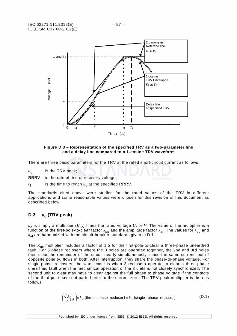
IEC 62271-111:2012(E) – 97 – IEEE Std C37.60-2012(E)
Published by IEC under license from IEEE. © 2012 IEEE. All rights reserved.
uc and E2
0
0
Vol
tage
u
(kV
)
2 parameter Referene line uc at t3
td t′ t3
Delay line of specified TRV
Time t (µs)
T2
1-cosine TRV Enveloppe E2 at T2
u′
Figure D.3 – Representation of the specified TRV as a two-parameter line and a delay line compared to a 1-cosine TRV waveform
There are three basic parameters for the TRV at the rated short-circuit current as follows.
uc is the TRV peak;
RRRV is the rate of rise of recovery voltage; t3 is the time to reach uc at the specified RRRV.
The standards cited above were studied for the rated values of the TRV in different applications and some reasonable values were chosen for this revision of this document as described below.
D.3 uc (TRV peak)
uc is simply a multiplier (Kuc) times the rated voltage Ur or V. The value of the multiplier is a function of the first-pole-to-clear factor kpp and the amplitude factor kaf. The values for kpp and kaf are harmonized with the circuit-breaker standards given in D.1.
The Kuc multiplier includes a factor of 1,5 for the first-pole-to-clear a three-phase unearthed fault. For 3 phase reclosers where the 3 poles are operated together, the 2nd and 3rd poles then clear the remainder of the circuit nearly simultaneously, since the same current, but of opposite polarity, flows in both. After interruption, they share the phase-to-phase voltage. For single-phase reclosers, the worst case is when 3 reclosers operate to clear a three-phase unearthed fault when the mechanical operation of the 3 units is not closely synchronized. The second unit to clear may have to clear against the full phase to phase voltage if the contacts of the third pole have not parted prior to the current zero. The TRV peak multiplier is then as follows.
( ) ( )recloser phase-singlerecloser phase-three1,53
ucuc kk =×
(D.1)
http://qstandard.org/
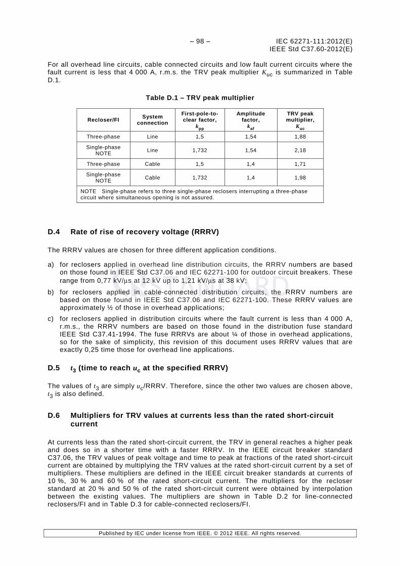
– 98 – IEC 62271-111:2012(E) IEEE Std C37.60-2012(E)
Published by IEC under license from IEEE. © 2012 IEEE. All rights reserved.
For all overhead line circuits, cable connected circuits and low fault current circuits where the fault current is less that 4 000 A, r.m.s. the TRV peak multiplier Kuc is summarized in Table D.1.
Table D.1 – TRV peak multiplier
Recloser/FI System connection
First-pole-to-clear factor,
kpp
Amplitude factor,
kaf
TRV peak multiplier,
Kuc
Three-phase Line 1,5 1,54 1,88
Single-phase NOTE Line 1,732 1,54 2,18
Three-phase Cable 1,5 1,4 1,71
Single-phase NOTE Cable 1,732 1,4 1,98
NOTE Single-phase refers to three single-phase reclosers interrupting a three-phase circuit where simultaneous opening is not assured.
D.4 Rate of rise of recovery voltage (RRRV)
The RRRV values are chosen for three different application conditions.
a) for reclosers applied in overhead line distribution circuits, the RRRV numbers are based on those found in IEEE Std C37.06 and IEC 62271-100 for outdoor circuit breakers. These range from 0,77 kV/µs at 12 kV up to 1,21 kV/µs at 38 kV;
b) for reclosers applied in cable-connected distribution circuits, the RRRV numbers are based on those found in IEEE Std C37.06 and IEC 62271-100. These RRRV values are approximately ½ of those in overhead applications;
c) for reclosers applied in distribution circuits where the fault current is less than 4 000 A, r.m.s., the RRRV numbers are based on those found in the distribution fuse standard IEEE Std C37.41-1994. The fuse RRRVs are about ¼ of those in overhead applications, so for the sake of simplicity, this revision of this document uses RRRV values that are exactly 0,25 time those for overhead line applications.
D.5 t3 (time to reach uc at the specified RRRV)
The values of t3 are simply uc/RRRV. Therefore, since the other two values are chosen above, t3 is also defined.
D.6 Multipliers for TRV values at currents less than the rated short-circuit current
At currents less than the rated short-circuit current, the TRV in general reaches a higher peak and does so in a shorter time with a faster RRRV. In the IEEE circuit breaker standard C37.06, the TRV values of peak voltage and time to peak at fractions of the rated short-circuit current are obtained by multiplying the TRV values at the rated short-circuit current by a set of multipliers. These multipliers are defined in the IEEE circuit breaker standards at currents of 10 %, 30 % and 60 % of the rated short-circuit current. The multipliers for the recloser standard at 20 % and 50 % of the rated short-circuit current were obtained by interpolation between the existing values. The multipliers are shown in Table D.2 for line-connected reclosers/FI and in Table D.3 for cable-connected reclosers/FI.
http://qstandard.org/

IEC 62271-111:2012(E) – 99 – IEEE Std C37.60-2012(E)
Published by IEC under license from IEEE. © 2012 IEEE. All rights reserved.
For fault currents less than 4 000 A r.m.s., the multipliers for the TRV peak voltage and time to peak are set at 1,0 since the fuse standard does not differentiate these values at currents less than the rated short-circuit current.
Table D.2 – TRV multipliers for line-connected reclosers/FI
Per unit rated current
Peak multiplier KE2
t3 multiplier Kt3
RRRV multiplier Kuc/Kt3
From IEEE Std C37.06 0,10 1,17 0,40 2,93
Interpolated 0,20 1,15 0,40 2,87
From IEEE Std C37.06 0,30 1,13 0,40 2,83
Interpolated 0,50 1,09 0,58 1,88
From IEEE Std C37.06 0,60 1,07 0,67 1,60
From IEEE Std C37.06 1,00 1,00 1,00 1,00
NOTE The values for KE2 and Kt3 are the same as those in IEEE Std C37.06.
Table D.3 – TRV multipliers for cable-connected reclosers/FI
Per unit rated current
Peak multiplier KE2
t3 multiplier Kt3
RRRV multiplier Kuc/Kt3
From IEEE Std C37.06 0,10 1,21 0,22 5,46
Interpolated 0,20 1,15 0,22 5,32
From IEEE Std C37.06 0,30 1,14 0,22 5,14
Interpolated 0,50 1,09 0,37 3,34
From IEEE Std C37.06 0,60 1,07 0,44 2,44
From IEEE Std C37.06 1,00 1,00 1,00 1,00
NOTE The values for KE2 and Kt3 are the same as those in IEEE Std C37.06 and are derived from IEC 62271-100. The actual values in used for RRRV are based on system studies.
http://qstandard.org/

– 100 – IEC 62271-111:2012(E) IEEE Std C37.60-2012(E)
Published by IEC under license from IEEE. © 2012 IEEE. All rights reserved.
Annex E (normative)
Tolerances for test values
E.1 General
During type tests, the following types of tolerances may normally be distinguished:
• tolerances on test quantities which directly determine the stress of the test object;
• tolerances concerning features or the behaviour of the test object before and after the test;
• tolerances on test conditions;
• tolerances concerning parameters of measurement devices to be applied.
A tolerance is defined as the range of the test value specified in the standard within the measured test value shall lie for a test to be valid. In certain cases the test may remain valid even if the measured value falls outside the range; this is the case when it results in a more severe test condition.
E.2 Type test tolerances
Any deviation of the measurement test value and the true test value caused by the uncertainty of the measurement are not taken into account in this respect. The basic rules for application of tolerances on test quantities during type tests are as follows:
a) testing stations shall aim wherever possible for the test value specified; b) the tolerances on test quantities specified shall be observed by the testing station. Higher
stresses exceeding those tolerance are permitted only with the consent of the manufacturer;
c) where, for any test quantity, no tolerance is given within this standard, or the standard to be applied, the type test shall be not less severe than specified. The upper stress limits are subject to the consent of the manufacturer;
d) if, for any test quantity, only one limit is given, the other limit shall be considered to be as close as possible to the specified value.
The tolerances on test quantities for type tests shall be as shown in Table E.1.
http://qstandard.org/

IEC 62271-111:2012(E) – 101 – IEEE Std C37.60-2012(E)
Published by IEC under license from IEEE. © 2012 IEEE. All rights reserved.
Table E.1 – Tolerances on test quantities for type tests
Subclause Designation of the test
Test quantity Specified test value Test tolerances/ limits of test
values
6.2 Dielectric tests
6.2.6.1 Power-frequency voltage tests
Test voltage (r.m.s. value)
Rated short-duration power-frequency withstand voltage
±1 %
Frequency -- 45 Hz to 65 Hz
Wave shape Peak value / r.m.s. value = 2 ±5 %
6.2.6.2 Lightning impulse voltage tests
Peak value Rated lightning impulse withstand voltage ±3 %
Front time 1,2 μs ±30 %
Time to half-value 50 μs ±20 %
6.4 Measurement of the resistance of the main circuit
DC test current IDC --
Lesser of 25 % to 50 % of rated (normal) current (Ir) or 100 A
6.5 Temperature-rise tests
Ambient air velocity -- ≤ 0,5 m/s
Test current frequency Rated frequency +2 % / -5 %
Test current Rated normal current
+2 % / -0 %
These limits are only required for the last two hours of testing period.
6.6
Short-time withstand current and peak withstand current tests
Test frequency Rated frequency ±10 %
Peak current (in one outer phase)
Rated peak withstand current +5 % / -0 %
Average of a.c. component of three-phase test current
Rated short-time withstand current ±5 %
A.c. component of test current in any phase/average
1,0 ±10 %
Short-circuit current duration
Rated short-circuit duration
See tolerances for I2t
Value of I2t Rated value I2t +10 % / -0 %
6.101 Capacitive current switching tests
Power frequency voltage variation Rated frequency ≤ 2 %
Voltage decay of recovery voltage 300 ms after arc extinction
≤ 10 %
r.m.s. value/ r.m.s. value of fundamental component
≤ 1,2
Test voltage 6.101.7 +3 % / -0 %
Frequency of the recovery voltage Rated frequency ±2 %
Rated capacitive breaking current Rated Value
+10 %
-0 %
http://qstandard.org/

– 102 – IEC 62271-111:2012(E) IEEE Std C37.60-2012(E)
Published by IEC under license from IEEE. © 2012 IEEE. All rights reserved.
Subclause Designation of the test
Test quantity Specified test value Test tolerances/ limits of test
values
6.103.1.3 Test current
Breaking current in T20 20 % of rated short-circuit breaking current
+0 %
-25 %
Breaking current in T50 50 % of rated short-circuit breaking current ±10 %
Breaking current in T100
100 % of rated short-circuit breaking current
+5 % /-10 %
At least 2 test shall be performed at -0 % (see 6.103.3)
Peak short-circuit current in T100 Rated making current +10 % / -0 %
6.103.1.4 Power frequency test voltage
Applied voltage before short-circuit making tests
Higher voltages are acceptable with agreement between the manufacturer and test lab
+10 % / -0 %
Applied phase voltage deviation from three- phase average
±5 %
Power frequency recovery voltage
Rated voltage (Ur)/1,732 ±5 %
Recovery voltage of any pole at the end of the recovery period deviation from three-phase average value.
±20 %
6.103.1.5 Transient recovery voltage (TRV)
Peak value of TRV
See Tables 7 through 11 inclusive
+10 % / -0 %
Rate of rise of TRV +15 %
-0 %
Time delay td ±20 %
6.104 Critical current tests Breaking current See 6.104.2 ±20 %
6.105 Minimum tripping current tests
Rated minimum tripping current See 6.104 ±10 %
Test voltage See 6.104.1 Low voltage
http://qstandard.org/

IEC 62271-111:2012(E) – 103 – IEEE Std C37.60-2012(E)
Published by IEC under license from IEEE. © 2012 IEEE. All rights reserved.
Annex F (informative)
Definition for the automatic circuit recloser
F.1 Definition of a recloser
IEEE Std C37.100-1992 provides the official definition of an Automatic Circuit Recloser as follows:
“A self-controlled device for automatically interrupting and reclosing an alternating-current circuit, with a predetermined sequence of opening and reclosing followed by resetting, hold-closed, or lockout operation. Note: When applicable, it includes an assembly of control elements required to detect overcurrents and control the recloser operation.” [IEEE Std C37.100-1992]
An automatic circuit recloser always consists of (i) a switching device, (ii) a control unit and (iii) sensors for current and/or voltage sensing.
F.2 Background
The electrical grid has evolved through innovation and application of technology. Initial distribution circuits consisted primarily of circuit breakers in the substation and expulsion fuses on the distribution feeder. Many early overhead distribution systems consisted of long radial feeders that often stretched to distances of fifty or more miles serving remote rural loads. The circuit protection on the feeder offered only limited fuse savings due to system coordination constraints of low fault currents, pickup settings, and existing protective devices. When a line fuse interrupted a fault on the grid, service restoration may have taken up to days to repair based upon location and service restoration plans.
System studies on an overhead distribution systems report that 70 % to 80 % of faults are temporary in nature and upon successful interruption by a fault-clearing device, last only a few cycles for higher fault current levels. With minimal system coordination, a fuse operation results in an unneeded “permanent” service interruption when no “permanent” system fault or problem exists.
The automatic circuit recloser was developed in the 1940’s to address this service reliability problem. Developed long before the existence of sophisticated electronic relays and controls, the recloser added an important tool for the utility to improve electrical service. The recloser offered “reclosing” after a fault interruption with low pickup settings and a variety of different time-current curves to improve system coordination. The recloser provides both temporary fault protection and avoidance of an outage and for a permanent fault, contains the outage to a minimum area. Reclosers are designed to provide up to three reclose intervals to offer three chances to reclose, preventing a prolonged outage if the final reclose is successful.
F.3 Recloser classifications
Automatic circuit reclosers are classified on the basis of single or three phase, type of controls (hydraulic or electronic), and type of interrupter (oil, SF6 or vacuum). Each recloser classification is required to meet the electrical and mechanical requirements and ratings as established in this document. In general, a recloser with a vacuum interrupter has been rated at 400 % duty cycle compared to an oil interrupting recloser.
http://qstandard.org/

– 104 – IEC 62271-111:2012(E) IEEE Std C37.60-2012(E)
Published by IEC under license from IEEE. © 2012 IEEE. All rights reserved.
Single-phase reclosers are used for protection of single-phase lines, such as branches or taps of a three-phase feeder. They are also being used on three-phase circuits where the load is predominantly single phase. Thus, when a permanent phase-to-earth fault occurs, one phase can be locked out while service is maintained to the remaining two-thirds of the system.
Three phase reclosers are used where lockout of all three phases is required for any permanent fault, to prevent single phasing of three-phase loads such as large three-phase motors.
F.4 Recloser operating characteristics
There are also established industry definitions and performance expectations with the following operating characteristics:
1) Tripping and control: The tripping time is identified as the Time Current Curve (TCC) and includes both the control’s characteristic and the mechanism operation time. This total time is called the total clearing time and will vary based upon the fault current level.
2) Lock-open function: The lockout function prevents any further reclosing operations and may also be initiated by local or supervisory commands.
3) Reclosing interval: The reclosing interval is the open time duration between trip operations and the reclose of the primary contacts. Refer to Figure 1 and Annex L. The recloser provides multiple reclose attempts, typically three, to prevent an outage. While some manufacturers have offered four reclose interval for five trips to lockout operation sequence, the standard number of reclose intervals is three in the industry.
4) Resetting interval: The reset interval is the time duration after one or more operations to reset the operations to the total number of programmed operations. For a typical four-trip operation recloser, if the fault is a temporary fault, and the recloser successfully recloses on the second reclose intervals, the resetting interval is the time for the recloser to return to the four trip, three reclose operating sequence.
http://qstandard.org/

IEC 62271-111:2012(E) – 105 – IEEE Std C37.60-2012(E)
Published by IEC under license from IEEE. © 2012 IEEE. All rights reserved.
Annex G (informative)
Definition for the fault interrupter
G.1 Definition of a fault interrupter
IEEE Std C37.100 provides the official definition of a fault interrupter as follows:
“A self-controlled mechanical switching device capable of making, carrying, and automatically interrupting an alternating current. It includes an assembly of control elements to detect overcurrents and control the fault interrupter.” [IEEE Std C37.100-1992]
A fault interrupter always consists of (i) a switching device, (ii) a control unit and (iii) sensors for current and/or voltage sensing.
G.2 Background
The fault interrupter is a device that was developed to protect underground distribution systems by interrupting and isolating faults in a cable system. The fault interrupter is similar to a recloser in that it is a self-controlled mechanical switching device with its own control elements. The ratings and test requirements are similar.
The main difference between a recloser and a fault interrupter is that while a recloser is capable of auto-reclosing, a fault interrupter automatically locks out on the first operation. The philosophy of a fault interrupter is that a fault in a cable or cable-connected load is very likely a permanent fault; a reclose operation will not be successful, rather would likely cause more damage to the system.
G.3 Fault interrupter application
It is assumed that a fault interrupter will be applied to a cable connected system. As such, the rate of rise of recovery voltage (RRRV) will be much lower that an overhead distribution feeder line due to the capacitance of the cable.
http://qstandard.org/

– 106 – IEC 62271-111:2012(E) IEEE Std C37.60-2012(E)
Published by IEC under license from IEEE. © 2012 IEEE. All rights reserved.
Annex H (informative)
Basis of derivation of duty factors and standard operating duties
H.1 General
NOTE This annex is adapted from IEEE Std C37.61-1973 Appendix C.
The total operating duty factor for automatic circuit reclosers is a function of the interrupting rating and is normally established on the basis of the empirical curve shown in Figure H.1. The operating duty at the three test currents used in the standard operating duty tests are apportioned as shown in Table H.1.
Table H.1 – Apportionment of operating duty
Duty-cycle test current percent of symmetrical. interrupting
current rating
Percent of total operating duty factor
100 50
50 37,5
20 12,5
H.2 Standard operating duty
The standard operating duty is based on the empirical equation:
Operating duty = (interrupting current)1,5 × (number of operations)
The number of unit operations at each test current of the standard operating duty test is calculated by dividing the total duty factor at the test current by the operating duty per interruption, where the operating duty per interruption is equal to I1,5.
NOTE ( ) III ×=1,5 .
This number is rounded off to the nearest multiple of four operations, except at maximum interrupting rating, when this approximation may distort the distribution greatly. At maximum interrupting, the nearest even number of operations should be used.
After the unit operations at each test current have been determined, the total standard duty cycle is recalculated. If necessary, adjustments in the number of unit operations (in multiples of four operations) at the 20 % and 50 % test currents may be made to bring the total duty factor close to the empirical value determined from the curve of Figure H.1.
Example: Assume an oil circuit recloser having a symmetrical interrupting rating of 8 000 A at rated maximum voltage. From the curve of Figure H.1, the total duty factor should be 1 470 × 104.
The duty factor apportioned to each test current will be as illustrated in Table H.2.
http://qstandard.org/

IEC 62271-111:2012(E) – 107 – IEEE Std C37.60-2012(E)
Published by IEC under license from IEEE. © 2012 IEEE. All rights reserved.
Table H.2 – Example of apportionment of operating duty factor
Duty cycle test current A
Operating duty 104
8 000 (100 %) 735 (50 %)
4 000 (50 %) 551 (37,5 %)
1 600 (20 %) 184 (12,5 %)
1 470 (100 %)
The operating duty per interruption is calculated as illustrated in Table H.3.
Table H.3 – Example – Operating duty per interruption
Test current
A
Calculation Operating duty per unit operation
104
8 000 (8 000)1,5 71,6
4 000 (4 000)1,5 25,3
1 600 (1 600)1,5 6,4
The number of unit operations at each test current is calculated as follows and as illustrated in Table H.4:
operation per factorDuty current test the at factorduty Totaloperations unit of No. =
Table H.4 – Example – Unit operations at test current levels
Test current
A
Unit operations Operations rounded off
8 000 10,3 10
4 000 21,8 20
1 600 28,8 28
Recalculating the total duty factor, the final result is shown in Table H.5.
Table H.5 – Example – Duty Factor
Test current
A
Operating duty factor per operation
104
Number of operations
Operating duty factor
104
8 000 71,6 10 716
4 000 25,3 20 505
1 600 6,4 28 179
1 400
http://qstandard.org/
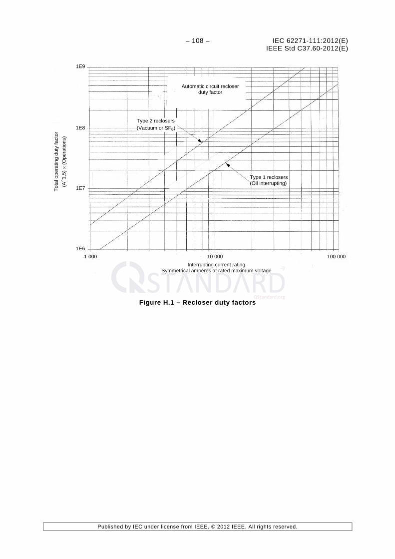
– 108 – IEC 62271-111:2012(E) IEEE Std C37.60-2012(E)
Published by IEC under license from IEEE. © 2012 IEEE. All rights reserved.
To
tal o
pera
ting
duty
fact
or
(A∧ 1,
5) ×
(Ope
ratio
ns)
1E9
1E8
1E7
1E6 1 000 10 000 100 000
Interrupting current rating Symmetrical amperes at rated maximum voltage
Automatic circuit recloser duty factor
Type 2 reclosers (Vacuum or SF6)
Type 1 reclosers (Oil interrupting)
Figure H.1 – Recloser duty factors
http://qstandard.org/

IEC 62271-111:2012(E) – 109 – IEEE Std C37.60-2012(E)
Published by IEC under license from IEEE. © 2012 IEEE. All rights reserved.
Annex I (normative)
Ratings for oil interrupting reclosers and
hydraulically controlled reclosers
I.1 General
Most reclosers designed prior to 1960 were series-trip reclosers that were hydraulically controlled. Furthermore, most reclosers designed in this period used oil interrupters. Later designs introduced electronic controls and other interrupting technologies, including vacuum and SF6.
This annex provides the rating structure unique to these traditional recloser designs, recognizing that hydraulically controlled reclosers using either oil or vacuum interrupters continue to be manufactured and installed in some countries.
The design and construction requirements for hydraulically controlled series-trip and oil interrupting reclosers are given in Clause 5 of this standard as applicable.
The design (type) tests for hydraulically controlled series-trip and oil interrupting reclosers are given in Clause 6 of this standard as applicable except that the performance characteristics are specified in Table I.3 and Table I.4.
I.2 Rating structure for hydraulically controlled series-trip and oil interrupting reclosers
I.2.1 General
The ratings of hydraulically controlled series-trip and oil interrupting reclosers are given in Clause 4 of this standard except as specified in I.2.2, I.2.3, I.2.4 and I.2.5.
I.2.2 Rated maximum voltage
The rated maximum voltage indicates the upper limit of the highest voltage of the system for which reclosers/FIs are intended to operate.
The preferred values of rated voltage of hydraulically controlled series-trip reclosers and oil interrupting are those shown in Column (2) of Table I.3 and Table I.4.
I.2.3 Rated continuous (normal) current (Ir)
Clause 4.4.1 of IEEE Std C37.100.1-2007 or IEC 62271-1:2007 is not applicable.
The preferred ratings for the continuous (normal) current of hydraulically controlled reclosers and oil interrupting reclosers are those shown in Table I.1.
http://qstandard.org/

– 110 – IEC 62271-111:2012(E) IEEE Std C37.60-2012(E)
Published by IEC under license from IEEE. © 2012 IEEE. All rights reserved.
Table I.1 – Preferred continuous (normal) current ratings for hydraulically controlled series-trip and oil interrupting reclosers
Recloser Preferred continuous (normal)
current ratings
A
Hydraulically controlled series-trip reclosers
5
10
15
25
35
50
70
100
140
200
280
400
560
Oil interrupting shunt-trip reclosers 50
100
280
400
560
1 120
I.2.4 Rated minimum tripping current for hydraulically controlled series-trip reclosers
The preferred rated minimum tripping current for hydraulically controlled series-trip reclosers shall be 1,5 to 2,0 times the continuous (normal) current rating with a tolerance of ±10 %.
I.2.5 Rated symmetrical interrupting current for hydraulically controlled series-trip reclosers and oil interrupting reclosers
The preferred rated symmetrical interrupting currents are given in Table I.2 for hydraulically controlled series-trip reclosers and Column (4) of Tables I.3 and Table I.4 for oil interrupting shunt-trip reclosers.
The rated symmetrical interrupting current shall be based on the capability of the reclosers to interrupt the corresponding asymmetrical current in circuits having X/R values as given in Columns (5), (7), and (9) of Table I.3 and Table I.4 and with a power-frequency recovery voltage equal to the rated maximum voltage and with transient recovery voltages as defined in Table 6, Table 7, Table 8, Table 9, Table 10, and Table 11.
I.2.6 Rated symmetrical making current
The rated symmetrical making current shall be the same value as the rated symmetrical interrupting current, with maximum asymmetry corresponding to the X/R ratio in column (9) of Table I.3 and Table I.4.
I.2.7 Rated operating sequence
The rated operating sequence for oil interrupting reclosers shall be:
O - t - CO - t' - CO - t' - CO
where:
O represents an open operation; CO represents a closing operation followed by an opening operation with a time delay
controlled by the automatic control of the device.
t = 2 s maximum and t' = 5 s maximum representing the rapid reclosing dead time of the device controlled by the automatic control of the device.
http://qstandard.org/

IEC 62271-111:2012(E) – 111 – IEEE Std C37.60-2012(E)
Published by IEC under license from IEEE. © 2012 IEEE. All rights reserved.
The operating sequence and dead time intervals represent the required capability of the device and shall be demonstrated in the standard operating duty test specified in 6.103.4 and 6.103.5. Other operating sequences, delays and dead times may be available for selection by the user.
I.3 Special test considerations for hydraulically controlled series-trip reclosers – Measurement of resistance of main circuit
See 6.4.1. Some hydraulically controlled reclosers have a rated continuous (normal) current rating well below 100 A where a resistance measurement at 50 A is not possible.
The current during the test shall be between 25 % and 50 % of the rated continuous (normal) current or 100 A (d.c.), whichever is lower. Higher current levels may be used if allowed by the manufacturer. The measured resistances after the test shall not differ by more than 20 % from the pre-test resistance.
http://qstandard.org/

– 112 – IEC 62271-111:2012(E) IEEE Std C37.60-2012(E)
Published by IEC under license from IEEE. © 2012 IEEE. All rights reserved.
Table I.2 – Preferred values for symmetrical interrupting current ratings of hydraulically controlled series-trip reclosers
Symmetrical interrupting current rating
(A)
Single phase reclosers
Continuous (normal) current Rating,
A
Recloser line number (Column (1), Table I.3)
1 2 3 4 5 6 7
Rated maximum voltage
kV
15 15,5 15,5 15,5 27,0 27,0 38,0
5 125 200 -- -- 200 -- --
10 250 400 -- -- 400 -- --
15 375 600 -- -- 600 -- --
25 625 1 000 1 500 -- 1 000 -- --
35 875 1 400 2 100 -- 1 400 -- --
50 1 250 2 000 3 000 -- 2 000 3 000 --
70 -- 2 000 4 000 -- 2 500 4 000 --
100 -- 2 000 4 000 6 000 2 500 4 000 6 000
140 -- -- 4 000 8 400 -- 4 000 8 000
200 -- -- 4 000 10 000 -- 4 000 8 000
280 -- -- 4 000 10 000 -- 4 000 8 000
400 -- -- -- 10 000 -- -- 8 000
560 -- -- -- 10 000 -- -- 8 000
Three-Phase Reclosers
Recloser Line Number (Column (1), Table I.4)
1 2 3 4 5 & 9 8 13
Rated Maximum Voltage, kV
15 15,5 15,5 15,5 15,5 & 27 27 38
5 125 200 -- -- -- 200 --
10 250 400 -- -- -- 400 --
15 375 600 -- -- -- 600 --
25 625 1 000 1 500 1 500 -- 1 000 1 500
35 875 1 400 2 100 2 100 -- 1 400 2 100
50 1 250 2 000 3 000 3 000 -- 2 000 3 000
70 -- 2 000 4 000 4 000 -- 2 500 4 200
100 -- 2 000 4 000 4 000 6 000 2 500 6 000
140 -- -- 4 000 4 000 8 000 -- 6 000
200 -- -- 4 000 4 000 8 000 -- 6 000
280 -- -- 4 000 4 000 8 000 -- 6 000
400 -- -- -- 4 000 8 000 -- 6 000
560 -- -- -- -- 8 000 -- --
NOTE Performance characteristics are the same as shown in Table I.3 and Table I.4 for the same line number.
http://qstandard.org/

Pub
lishe
d by
IEC
und
er li
cens
e fr
om IE
EE
. © 2
012
IEE
E. A
ll rig
hts
rese
rved
.
IEC 62271-111:2012(E) – 113 – IEEE Std C37.60-2012(E)
Tabl
e I.3
– P
refe
rred
val
ues
for
sym
met
rica
l rat
ed in
terr
upti
ng c
urre
nt,
and
perf
orm
ance
cha
ract
eris
tics
of
sing
le-p
hase
oil
inte
rrup
ting
rec
lose
rs
S
tand
ard
oper
atin
g du
ty a
C
urre
nt r
atin
gs
A
Per
cent
of
inte
rrup
ting
rat
ing
15
-20
45-5
5 90
-100
Line
no
. R
ated
max
. vo
ltag
e
kV
Con
tinu
ous
(nor
mal
) S
ymm
etri
cal
inte
rrup
ting
X
/R b
Num
ber
of
unit
op
erat
ions
X/R
b N
umbe
r of
un
it
oper
atio
ns
X/R
b N
umbe
r of
un
it
oper
atio
ns
Tota
l nu
mbe
r of
un
it
oper
atio
ns
(1)
(2)
(3)
(4)
(5)
(6)
(7)
(8)
(9)
(10)
(1
1)
Sin
gle
Pha
se R
eclo
sers
/FIs
1 15
50
1
250
2 40
4
40
8 20
10
0
2 15
,5
100
2 00
0 2
32
5 24
10
12
68
3 15
,5
280
4 00
0 3
32
6 20
12
12
64
4 15
,5
560
10 0
00
4 28
8
20
c 10
58
5 27
10
0 2
500
2 32
5
24
12
12
68
6 27
28
0 4
000
3 32
6
20
13
12
64
7 38
56
0 8
000
4 28
8
20
c 10
58
a Th
ese
are
perf
orm
ance
cha
ract
eris
tics
spec
ified
as
test
req
uire
men
ts in
this
sta
ndar
d.
b Fo
r te
st p
urpo
ses,
X/R
val
ues
are
min
imum
val
ues.
Ref
er to
4.1
02 a
nd 6
.103
.2.
c R
ef. c
olum
n (9
): X
/R =
14
for
50 H
z an
d 17
for
60 H
z fo
r a
time
cons
tant
of 4
5 m
s.
http://qstandard.org/

Pub
lishe
d by
IEC
und
er li
cens
e fr
om IE
EE
. © 2
012
IEE
E. A
ll rig
hts
rese
rved
.
– 114 – IEC 62271-111:2012(E) IEEE Std C37.60-2012(E)
Tabl
e I.4
– P
refe
rred
val
ues
for
rate
d sy
mm
etri
cal i
nter
rupt
ing
curr
ent,
an
d pe
rfor
man
ce c
hara
cter
isti
cs o
f th
ree-
phas
e oi
l int
erru
ptin
g re
clos
ers
S
tand
ard
oper
atin
g du
ty a
C
urre
nt R
atin
gs (
A)
Per
cent
of
inte
rrup
ting
rat
ing
15
-20
45-5
5 90
-100
Line
N
o.
Rat
ed m
ax.
Vol
tage
kV
Con
tinu
ous
(nor
mal
) S
ymm
etri
cal
inte
rrup
ting
X
/R b
Num
ber
of
unit
op
erat
ions
X/R
b
Num
ber
of
unit
op
erat
ions
X/R
b
Num
ber
of
unit
op
erat
ions
Tota
l nu
mbe
r of
un
it
oper
atio
ns
(1)
(2)
(3)
(4)
(5)
(6)
(7)
(8)
(9)
(10)
(1
1)
Thre
e P
hase
Rec
lose
rs/F
Is
1 15
50
1
250
2 40
4
40
8 20
10
0
2 15
,5
100
2 00
0 2
32
5 24
10
12
68
3 15
,5
280
4 00
0 3
32
6 20
12
12
64
4
15,5
40
0
5 15
,5
560
8 00
0 3
28
7 20
c
10
58
6 15
,5
560
16 0
00
4 28
8
20
c 10
58
7
15,5
1
120
8 27
10
0 2
500
2 32
5
24
12
12
68
9 27
56
0 8
000
4 28
8
20
c 10
58
10
27
56
0 10
000
11
27
1 12
0 8
000
12
27
560
12 0
00
13
38
400
6 00
0 4
28
8 24
c
10
62
14
38
560
8 00
0 4
28
8 20
c
10
58
a Th
ese
are
perf
orm
ance
cha
ract
eris
tics
spec
ified
as
test
req
uire
men
ts in
this
sta
ndar
d.
b Fo
r te
st p
urpo
ses,
X/R
val
ues
are
min
imum
val
ues.
Ref
er to
4.1
02 a
nd 6
.103
.2.
c R
ef. c
olum
n (9
): X
/R =
14
for
50 H
z an
d 17
for
60 H
z fo
r a
time
cons
tant
of 4
5 m
s.
http://qstandard.org/

IEC 62271-111:2012(E) – 115 – IEEE Std C37.60-2012(E)
Published by IEC under license from IEEE. © 2012 IEEE. All rights reserved.
Annex J (normative)
Standard methods for determining the values of a sinusoidal
current wave and a power-frequency recovery voltage
J.1 General
NOTE Material in this annex has been taken from IEEE Std C37.09-1999, similar material can be found in IEC 62271-1.
This annex describes methods for measuring oscillograms to determine the transient currents in a short circuit and the power-frequency recovery voltages following the interruption of a short circuit. These include:
a) the r.m.s. or effective value, measured from the envelope of an asymmetrical sinusoidal wave at a time such as the time of the maximum peak of the time of contact parting;
b) the r.m.s. value of a short-circuit current over several cycles; and c) the r.m.s. value of a power-frequency recovery voltage following circuit interruption.
J.2 Currents
J.2.1 Significance of r.m.s. values used in the standards on a.c. high-voltage reclosers/FIs
R.m.s. values of sinusoidal currents vary with the time over which the square of the current is integrated. For the purpose of current measurements on a.c. high-voltage reclosers/FIs, a r.m.s. value is used that varies with the values of the components determined from the envelope of the current wave.
When a current is specified as a r.m.s. value at a given instant determined from the envelope of the current wave, the d.c. component and the peak-to-peak value of the a.c. component are assumed to remain constant at the values existing at the given instant, and the integration is made over a time of one cycle.
When a current is specified as an r.m.s. value over a time of several cycles, the integration may be based on the instantaneous values of current over this time or, more easily, the r.m.s. current may be determined by the method in J.2.6.
J.2.2 Classification of current wave
Sinusoidal waves may be divided into those that are symmetrical about the zero axis and those that are asymmetrical with respect to the zero axis.
J.2.3 R.m.s. value of a symmetrical sinusoidal wave at a particular instant
A symmetrical sinusoidal wave has a r.m.s. value equal to its peak-to-peak value divided by 2,828. 11
————————— 11 The value of 2,828 is equal to 22 .
http://qstandard.org/

– 116 – IEC 62271-111:2012(E) IEEE Std C37.60-2012(E)
Published by IEC under license from IEEE. © 2012 IEEE. All rights reserved.
To determine the r.m.s. value at a given instant, draw the envelope of the current wave (through the center of the trace), determine the peak-to-peak value, (A), at the given instant and divide by 2,828 (see Figure J.1).
Enveloppe
Zero line
RMS value
Enveloppe
t
A B
NOTE See Figure J.2 for explanation of parameters in this figure.
Figure J.1 – Measurement of the r.m.s. value of a symmetrical wave
J.2.4 R.m.s. value of an asymmetrical sinusoidal wave at a particular instant
J.2.4.1 General
An asymmetrical sinusoidal wave can be considered to be composed of two components: an alternating current component and a direct current component. The r.m.s. value of such a current at a given instant is the square root of the sum of the squares of the d.c. and a.c. components of current at the instant the measurement is made (see Figure J.2).
t is the instant for which measurement is made A' is the major ordinate B' is the minor ordinate A is the peak-to-peak value of alternating component (a.c. component), A = A' + B'
D is the direct component (d.c. component), 2
'' BAD −=
B = r.m.s. value = 22
22
22component) (d.c.component) a.c. of value (r.m.s. DA +
=+ (J.1)
http://qstandard.org/

IEC 62271-111:2012(E) – 117 – IEEE Std C37.60-2012(E)
Published by IEC under license from IEEE. © 2012 IEEE. All rights reserved.
Enveloppe
Zero line
RMS value
Enveloppe
t
A B
D
A′
B′
DC component
Figure J.2 – Measurement of the r.m.s. value of an asymmetrical wave
J.2.4.2 Alternating component
The alternating component has a peak-to-peak value (A) equal to the distance between the upper and lower envelopes of the current, and the axis of the wave is located midway between the envelopes. The peak value of this current is given by:
2
''2
nateMinor.ordinateMajor.ordicomponenta.c.ofvaluePeak BA +=+= (J.2)
J.2.4.3 Direct component
The amplitude of the d.c. component is measured with respect to the displaced axis of the alternating component and is equal to:
2
''2
nateMinor.ordi-nateMajor.ordi BA −= (J.3)
J.2.4.4 Calculation of the r.m.s. value of an asymmetrical sinusoidal wave
See Figure J.2 for the method of calculation.
J.2.5 Alternate methods of stating the making current
The making current may be stated as either a r.m.s. current, measured from the envelope of the current wave at the time of the maximum peak, or as the instantaneous value of the current at the peak. These values are equally significant in the description of asymmetrical making currents, but the units shall be clearly stated to avoid confusion. The ratio of the peak value of current to the r.m.s. value varies with asymmetry (Table J.1) as follows:
The ratio of the peak value to the r.m.s. value is 1,69 ±2 % if the asymmetry is between 22 % and 94 % and 1,69 ±3 % if the asymmetry is from 20 % to 100 %. The variation in this ratio is so small that 1,69 can be used without introducing serious error. Currents having 20 % or less asymmetry are considered to be symmetrical and should not be used for demonstrating required current-making capability.
http://qstandard.org/

– 118 – IEC 62271-111:2012(E) IEEE Std C37.60-2012(E)
Published by IEC under license from IEEE. © 2012 IEEE. All rights reserved.
Table J.1 – Asymmetrical currents tabulated values
% Asymmetry Peak value R.m.s. value
Peak value to r.m.s. value
100 2,83 1,73 1,63
90 2,69 1,62 1,66
80 2,55 1,51 1,69
70 2,40 1,41 1,71
60 2,26 1,31 1,73
50 2,12 1,23 1,73
40 1,98 1,15 1,72
30 1,84 1,09 1,69
24 1,75 1,06 1,66
20 1,70 1,04 1,63
10 1,56 1,01 1,54
0 1,41 1,00 1,41
J.2.6 Measurement of the r.m.s. value of a current during a short circuit of several cycles duration
The oscillogram shown in Figure J.3 represents a record of a short circuit of several cycles duration. Time is shown on the axis OX and the current values on the OY axis. The origin O of the coordinates represents the beginning of the short circuit, and OT represents the duration of the current flowing through the reclosers/FIs.
http://qstandard.org/

IEC 62271-111:2012(E) – 119 – IEEE Std C37.60-2012(E)
Published by IEC under license from IEEE. © 2012 IEEE. All rights reserved.
A
O
C
Y
D
X
T
B
I0
I1
I2 I3
I4 I5
I6 I7 I8
I9 I10
I1
1 2 3 4 5 6 7 8 9 10
Key
OT duration of short circuit
AB upper envelope of current wave
CD lower envelope of current wave
I0 - I10 r.m.s. value of asymmetrical current at each instant
Figure J.3 – Determination of the equivalent r.m.s. value of a short-time current
The r.m.s. value of the current Irms during the time interval O to T is given by the following equation:
tII i dT
T
02
rms ∫= (J.4)
where i is the instantaneous value of the current.
The equivalent r.m.s. value of the current may be determined with sufficient accuracy by the following application of the Simpson’s equation:
a) divide the time interval OT into 10 equal parts; b) for the eleven instants 0 through 10, determine the total r.m.s. currents, I0 through I10 (the
method described in J.2.4.4 may be used). The values then are substituted in the equation below:
( ) ( )[ ]28
26
24
22
29
27
25
23
21
210
20rms 24
301 IIIIIIIIIIII ++++++++++= (J.5)
In using this equation on currents with a d.c. component that decays to less than 5 % of its initial value during the first time interval, it is more accurate to ignore the d.c. component than to consider it.
http://qstandard.org/

– 120 – IEC 62271-111:2012(E) IEEE Std C37.60-2012(E)
Published by IEC under license from IEEE. © 2012 IEEE. All rights reserved.
In some cases, the duration of a test demonstrating short-circuit current carrying may not be exactly as specified. However, since the heating of the current carrying parts is very nearly proportional to i2dt, and the time for cooling is short, the r.m.s. test current IA determined by this method is considered to demonstrate the ability of the recloser/FI to carry the specified current IB, if the duration TA of the short-circuit current is within 25 % of the specified time TB and if IA
2×TA is equal or greater than IB2×TB.
J.3 Power-frequency recovery voltage
The power-frequency recovery voltage shall be determined from the envelope of each voltage wave at a point in time coincident with that peak that occurs more than 1/2 cycle and not more than one cycle after final arc extinction in the last phase to clear. The power frequency phase-to-phase recovery voltage for a three-phase short circuit shall be taken as 1,73 times the average of the three values obtained in this manner for the three voltage waves (see Figure J.4).
0
G1 0 G2
E3
E2
E1
G2
G1
1 f
1 2 f
Phase A
Phase B
Phase C
Phase A = first pole-to-clear
OO is the instant of final arc extinction
G1G1 is the instant after interval 1/(2f) from OO
G2G2 is the instant after interval 1/(2f) from OO
f is the power frequency
2,8281E is the power frequency recovery voltage, phase A
2,8282E is the power frequency recovery voltage, phase B
2,8283E is the power frequency recovery voltage, phase C
Average power frequency pole-unit recovery voltage
= 3
2,8282,8282,828321
++ EEE
Power frequency phase-to-phase recovery voltage = voltage)recovery unit-polefrequency power 3(Average
Figure J.4 – Determination of the power-frequency pole unit recovery voltage
http://qstandard.org/

IEC 62271-111:2012(E) – 121 – IEEE Std C37.60-2012(E)
Published by IEC under license from IEEE. © 2012 IEEE. All rights reserved.
Annex K (normative)
Altitude correction factors
K.1 General
NOTE The following paragraph is adapted from IEEE Std C37.100.1-2007, Annex B.
The altitude correction factors used in this standard are based on two factors. The first factor is that, historically, insulation coordination has had enough margin to safely use equipment up to about 1 000 m without further consideration. The second factor is the actual physics of the behavior of the insulation withstand level of external insulation that is approximated by the equation given in Figure K.1. This equation recognizes that the insulation withstand level of external insulation decreases with increasing altitude beginning at sea level, not at 1 000 m. The background of this equation is given in IEEE Std 4 and IEC 60071-2:1996.
K.2 Altitude correction factors
The altitude correction factors for application of reclosers/FI’s above 1 000 m shall be taken from Figure K.1. Refer to IEEE Std C37.100.1-2007 for additional information.
Figure K.1 – Altitude correction factors
http://qstandard.org/

– 122 – IEC 62271-111:2012(E) IEEE Std C37.60-2012(E)
Published by IEC under license from IEEE. © 2012 IEEE. All rights reserved.
The altitude correction factor can be calculated with the following equation taken from 4.2.2 of IEC 60071-2:1996:
= 8150a
HmeK
where
H is the altitude (in m); m is taken as fixed value in each case for simplification as follows:
m = 1 for power-frequency, lightning impulse, and phase-to-phase switching impulse voltages
m = 0,9 for longitudinal switching impulse voltage (i.e., across the isolation gap) m = 0,75 for phase-to-earth switching impulse voltage
http://qstandard.org/

IEC 62271-111:2012(E) – 123 – IEEE Std C37.60-2012(E)
Published by IEC under license from IEEE. © 2012 IEEE. All rights reserved.
Annex L (informative)
Comparison of definitions related to the unit operation
L.1 General
The unit operation as defined in 3.1.112 and illustrated in Figure 1 is simplified for the purposes of this standard for an automatic circuit recloser. Some of the time intervals shown in Figure 1 are identical to similar terms use in relay communities of both IEEE and IEC. In an effort to promote a better understanding of the various terms in use, this annex presents a comparison of terms as used in this standard and in IEC.
L.2 Broader reclose operation
A broader view of a full reclose operation is shown in Figure L.1. This figure illustrates many more terms and time intervals associated with a full OPEN - X s - CLOSE-OPEN operation. Table L.1 provides a comparison of the terms as used this standard, Figure 1 and as used in relay standards.
http://qstandard.org/

– 124 – IEC 62271-111:2012(E) IEEE Std C37.60-2012(E)
Published by IEC under license from IEEE. © 2012 IEEE. All rights reserved.
Table L.1 – Comparison of terms
Term designation Alternate term designation
Point or Interval
(P or I) Note 2 Explanation
(1) (2) (3) (4)
Fault inception Initiation of short circuit P
Protection operating time Release delay I
Actuation of trip circuit
Trip circuit energized, Protection output raised
P Start of the opening command
Trip circuit energized I Duration while the control unit (controller) issues a trip signal
Auto reclosing initiated P Starts the Auto Reclose function of the control device
Opening time I Duration after actuation of trip circuit until the fault is cleared
Primary contact parting time
Contact parting time I Duration after energizing the trip circuit until the
contacts part
Primary contacts part P Primary contacts part and cause an arc, primary current not interrupted yet
Arcing time I
The arcing time terminates when the primary current crosses zero and extinguishes.
NOTE The primary contacts may not reach the final open position at this time.
Clearing time Fault clearing time I Duration from fault inception until fault cleared
Interrupting time I Duration after actuation of trip circuit until the fault is cleared
Fault cleared Final arc extinction P Marks the end of clearing time
Primary contacts fully open P Primary contacts have reached the open position
Protection resetting I Duration for the control device to reset after the fault has cleared
Protection reset P Marks the end of protection resetting
Trip signal cleared P Marks the instant when the control unit clears the trip signal
Auto-reclose open interval time
Auto-reclose dead time delay, reclosing interval
I This time is set at the control unit (controller), interval of zero current between the open and the reclose operations
Actuation of close circuit
Auto-reclose close output raised P Start of closing command
Unit operatiion Clearing time plus auto reclose open time
I Duration from fault inception until primary contact make following auto reclose
NOTE 1 The purpose of this table is to help in the interpretation of Figure K.1. The definitions given may not be in complete accordance with the official IEEE or IEC dictionary of terms.
NOTE 2 Each term designates a point (P) in time or a time interval (I) of time as noted in column (3).
http://qstandard.org/

IEC 62271-111:2012(E) – 125 – IEEE Std C37.60-2012(E)
Published by IEC under license from IEEE. © 2012 IEEE. All rights reserved.
Fault cleared
System current
Trip signal
Close signal
Recloser/ FI-primary contacts
Primary contact parting time
Arcing time
Primary contacts
part
Opening time
Interrupting time
Primary contacts fully open
Arc and fault extinguished
(final arc extinction)
Auto-reclosing initiated
Actuation of trip circuit
Protection operating
time
Protection resetting
Protection reset
Trip signal cleared
Fault inception
Load current
Clearing time Unit operation
Trip circuit energised
System dead time or auto-reclose open time (Notes 1, 2), reclosing interval (Note 3)
Primary contacts make
Auto-reclose reclaim time
Close circuit energised
Auto-reclose sequence
reset Actuation of close circuit
Closing time
Primary contacts closed
Primary contacts open
Primary contacts closed
CLOSE signal
TRIP signal
NOTE 1 Figure reflects a radial power line for simplification.
NOTE 2 Reference IEC 60050-448:1995, 448-16-09.
NOTE 3 Reference Figure 1 and 3.1.112.
Figure L.1 – Illustration of auto-reclose operation
http://qstandard.org/

– 126 – IEC 62271-111:2012(E) IEEE Std C37.60-2012(E)
Published by IEC under license from IEEE. © 2012 IEEE. All rights reserved.
Annex M (informative)
Corrosion protection
M.1 General
Equipment covered by this standard is often placed in harsh environments including submersible vaults and coastal areas subjected to salt air. While it is beyond the scope of this standard to specify specific requirements for these environments, references to other standards that treat this subject are provided together with a list of design areas that should be considered.
M.2 Reference documents
The following references are included in 1.2 or the Bibliography. They are repeated here for convenience. Test procedures are included in some of these references.
• IEC/TS 62271-304, High-voltage switchgear and controlgear – Part 304: Design classes for indoor enclosed switchgear and controlgear for rated voltages above 1 kV up to and including 52 kV to be used in severe climatic conditions [34]
• IEC 60529, Degrees of protection provided by enclosures (IP Code) [17]
• IEC 62208, Empty enclosures for low-voltage switchgear and controlgear assemblies –General Requirements [35]
• IEEE Std C57.12.28, IEEE Standard for Pad Mounted Equipment – Enclosure Integrity
• IEEE Std C57.12.29, IEEE Standard for Pad-Mounted Equipment – Enclosure Integrity for Coastal Environments [36]
• IEEE Std C57.12.31, IEEE Standard for Pole Mounted Equipment – Enclosure Integrity [37]
M.3 Other considerations
Other considerations for submersible and coastal environments include:
• protection against dissimilar metal contact;
• use of cathodic protection systems with replaceable protection anodes in the event that the primary coating system is damaged;
• use of high alloy stainless steel or galvanized steel;
• special consideration for earthing (grounding) wires and earth connections.
http://qstandard.org/

IEC 62271-111:2012(E) – 127 – IEEE Std C37.60-2012(E)
Published by IEC under license from IEEE. © 2012 IEEE. All rights reserved.
Bibliography
[1] IEEE Std C37.24™, IEEE Guide for Evaluating the Effect of Solar Radiation on Outdoor Metal-Enclosed Switchgear
[2] IEC 60721-2-2, Classification of environmental conditions – Part 2: Environmental conditions appearing in nature – Precipitation and wind
[3] IEEE Std C37.40™, IEEE Standard Service Conditions and Definitions for High-Voltage Fuses, Distribution Enclosed Single-Pole Air Switches, Fuse Disconnecting Switches, and Accessories
[4] IEC 60282-2:2008, High-voltage fuses – Part 2: Expulsion fuses
[5] Accredited Standards Committee C2-2012, National Electrical Safety Code® (NESC®)
[6] IEC 62271-210, High-voltage switchgear and controlgear – Part 210: Seismic qualification for metal enclosed switchgear and controlgear assemblies for rated voltages above 1 kV and up to and including 52 kV
[7] IEEE Std 386™-1995, IEEE Standard for Separable Insulated Connector Systems for Power Distribution Systems above 600 V
[8] IEEE Std 400.2™, IEEE Guide for Field Testing of Shielded Power Cable Systems Using Very Low Frequency (VFL)
[9] IEC/TR 60943:1998, Guidance concerning the permissible temperature rise for parts of electrical equipment, in particular for terminals
[10] IEC 60085, Electrical insulation – Thermal evaluation and designation
[11] IEC 60255-151, Measuring relays and protection equipment – Part 151: Functional requirements for over/under current protection
[12] IEC 60059, IEC standard current ratings
[13] IEEE Std C37.06.1™, IEEE Guide for AC High-Voltage Circuit Breakers Rated on a Symmetrical Current Basis—Designated “Definite Purpose for Fast Transient Recovery Voltage Rise Times
[14] IEEE Std C37.04b™, IEEE Standard for Rating Structure for AC High-Voltage Circuit Breakers Rated on a Symmetrical Current Basis
[15] IEEE Std C37.06™, IEEE Standard for AC High-Voltage Circuit Breakers Rated on a Symmetrical Current Basis—Preferred Ratings and Related Required Capabilities for Voltages above 1000 V
[16] IEEE Std C37.41™-2000, IEEE Standard Design Tests for High-Voltage (>1 000 V) Fuses, Fuse and Disconnecting Cutouts, Distribution Enclosed Single-Pole Air Switches, Fuse Disconnecting Switches, and Fuse Links and Accessories Used with These Devices
[17] IEC 60529, Degrees of protection provided by enclosures (IP Code)
[18] IEC 60502 (all parts), Power cables with extruded insulation and their accessories for rated voltages from 1 kV (Um = 1,2 kV) up to 30 kV (Um = 36 kV)
http://qstandard.org/

– 128 – IEC 62271-111:2012(E) IEEE Std C37.60-2012(E)
Published by IEC under license from IEEE. © 2012 IEEE. All rights reserved.
[19] IEC/TR 62271-306, High-voltage switchgear and controlgear – Part 306: Guide to IEC 62271-100, IEC 62271-1 and other IEC standards related to alternating current circuit-breakers12
[20] ANSI C37.85-2002 (2010), American National Standard for Switchgear Alternating-Current High-Voltage Power Vacuum Interrupters – Safety Requirements for X-Radiation Limits
[21] IEC 60068-2-17:1994, Basic environmental testing procedures – Part 2-17: Tests – Test Q: Sealing
[22] CAN/CSA C22.2 No. 31-M89, Switchgear Assemblies; Industrial Products
[23] IEEE Std C62.11™, IEEE Standard for Metal-Oxide Surge Arresters for AC Power Circuits (>1 kV)
[24] IEC 62271-102, High-voltage switchgear and controlgear – Part 102: Alternating current disconnectors and earthing switches
[25] AEIC CS8-00, Specification for Extruded Dielectric Shielded Power Cables Rated 5 through 46 kV
[26] IEC 62271-200, High-voltage switchgear and controlgear – Part 200: AC metal-enclosed switchgear and controlgear for rated voltages above 1 kV and up to and including 52 kV
[27] IEEE Std C37.20.7™, IEEE Guide for Testing Medium-Voltage Metal-Enclosed Switchgear for Internal Arcing Faults
[28] IEEE Std C37.90™, IEEE Standard for Relays and Relay Systems Associated with Electric Power Apparatus
[29] IEEE Std C37.90.2™, IEEE Standard for Withstand Capability of Relay Systems to Radiated Electromagnetic Interference from Transceivers
[30] IEEE Std C37.90.3™, IEEE Standard Electrostatic Discharge Tests for Protective Relays
[31] IEC 60255-22-2, Measuring relays and protection equipment – Part 22-2: Electrical disturbance tests – Electrostatic discharge tests
[32] IEC 60255-22-3, Measuring relays and protection equipment – Part 22-3: Electrical disturbance tests – Radiated electromagnetic field immunity
[33] IEC 60255-22-6, Electrical relays – Part 22-6: Electrical disturbance tests for measuring relays and protection equipment – Immunity to conducted disturbances induced by radio frequency fields
[34] IEC/TS 62271-304, High-voltage switchgear and controlgear – Part 304: Design classes for indoor enclosed switchgear and controlgear for rated voltages above 1 kV up to and including 52 kV to be used in severe climatic conditions
[35] IEC 62208, Empty enclosures for low-voltage switchgear and control gear assemblies – General Requirements
[36] IEEE Std C57.12.29™, IEEE Standard for Pad-Mounted Equipment – Enclosure Integrity for Coastal Environments
[37] IEEE Std C57.12.31™, IEEE Standard for Pole Mounted Equipment – Enclosure Integrity
————————— 12 To be published.
http://qstandard.org/

IEC 62271-111:2012(E) – 129 – IEEE Std C37.60-2012(E)
Published by IEC under license from IEEE. © 2012 IEEE. All rights reserved.
[38] IEC 60073, Basic and safety principles for man-machine interface, marking and identification – Coding principles for indicators and actuators
[39] IEC 60417, Graphical symbols for use on equipment
[40] ANSI C37.61-1973, IEEE Standard Guide for the Application, Operation and Maintenance of Automatic Circuit Reclosers
[41] IEC 60050-448:1995, Vocabulaire Electrotechnique International – Chapitre 448: Protection des réseaux d'énergie
[42] IEC 60507, Artificial pollution tests on high-voltage insulators to be used on a.c. systems
[43] IEC 60721-3-3, Classification of environmental conditions – Part 3: Classification of groups of environmental parameters and their severities – Section 3: Stationary use at weatherprotected locations
[44] IEC 60721-3-4, Classification of environmental conditions – Part 3: Classification of groups of environmental parameters and their severities – Section 4: Stationary use at non-weatherprotected locations
[45] IEC/TR 62271-300, High-voltage switchgear and controlgear – Part 300: Seismic qualification of alternating current circuit-breakers
[46] IEC 62271-2, High-voltage switchgear and controlgear – Part 2: Seismic qualification for rated voltages of 72,5 kV and above13
[47] IEC 60721 (all parts), Classification of environmental conditions
[48] IEC 62271-207, High-voltage switchgear and controlgear – Part 207: Seismic qualification for gas-insulated switchgear assemblies for rated voltages above 52 kV
___________
————————— 13 This publication was withdrawn.
http://qstandard.org/

http://qstandard.org/

http://qstandard.org/

INTERNATIONAL ELECTROTECHNICAL COMMISSION 3, rue de Varembé PO Box 131 CH-1211 Geneva 20 Switzerland Tel: + 41 22 919 02 11 Fax: + 41 22 919 03 00 [email protected] www.iec.ch
http://qstandard.org/


