Embed Size (px)
DESCRIPTION
Systems Environment 2. Quick Revision Review of Exercises Processor Instructions Introduction to TOM. Quick Revision. Diagram 3 The CPU Level. Central Processing Unit. Control Unit. Registers. Arithmetic & Logic Unit. The Register Level. A register is a collection of “cells”. - PowerPoint PPT Presentation
Citation preview

Systems Environment 2
Quick RevisionReview of ExercisesProcessor InstructionsIntroduction to TOM

Quick Revision

Diagram 3The CPU Level
Central Processing Unit
Control Unit Registers
Arithmetic & Logic Unit

The Register Level
A register is a collection of “cells”.
A register is a collection of “cells”.
Each cell is a “flip-flop” electronic device which can be in one of two stable states.
Each cell is a “flip-flop” electronic device which can be in one of two stable states.
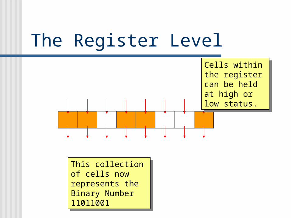
The Register LevelCells within the register can be held at high or low status.
Cells within the register can be held at high or low status.
This collection of cells now represents the Binary Number 11011001
This collection of cells now represents the Binary Number 11011001

The Register Level
Write
Read
Information comes in on 8 wires, using a write enable signal.
Information comes in on 8 wires, using a write enable signal.
Information is transferred (read) by using a similar read enable signal
Information is transferred (read) by using a similar read enable signal

Diagram 3The CPU Level
Central Processing Unit
Control Unit Registers
Arithmetic & Logic Unit

Diagram 4The ALU Level
Arithmetic & Logic Unit
Arithmetic Operations Logic Operations

Diagram 5The Logic Operation Level
Logic Operations
AND OR NOT COMPARE

Binary and Hexadecimal

Bytes The way that
information is coded is to use a sequence of zeros and ones
It is usual to have a sequence of 8 bits collected together
This is called a byte
10110101

Bits A bit is the smallest piece
of information in the computer
In a single cell, the digital information is either One - current is HIGH (ON) Zero -current is LOW (OFF)
There are no in-between states
ON
OFF

A 4-bit register Reading from the
right, each bit is worth double the one preceding it.
The sequence, reading from the right is: 1,2,4,8, ...
If we had more bits, it would continue: ... 16, 32, 64, etc.
148 2
4
is ON
1
is ON

Binary Numbers 1 The register shown on
the right represents the binary number 0101
This has ones in the 1 and 4 cells, and zeroes in the others.
The number represented is 5
148 2
4 1
0101
4+1 = 5

Binary Numbers 2 By Binary, we mean that numbers
are written in powers of two These are 1, 2, 4, 8, 16 etc. So that:
10100 = Which is 16 + 4 = 20
16 8 4 2 1
1 0 001

Converting Binary to Decimal Example: 101101 Reading from right to left the columns are
1,2,4,8 etc.
i.e. 32 16 8 4 2 11 0 1 1 0 1
So the number in decimal notation is:
32 + 8 + 4 + 1 = 45
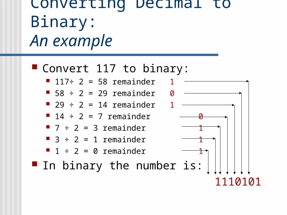
Converting Decimal to Binary:An example
Convert 117 to binary: 117÷ 2 = 58 remainder 1 58 ÷ 2 = 29 remainder 0 29 ÷ 2 = 14 remainder 1 14 ÷ 2 = 7 remainder 0 7 ÷ 2 = 3 remainder 1 3 ÷ 2 = 1 remainder 1 1 ÷ 2 = 0 remainder 1
In binary the number is: 1110101

Adding in Binary There are only four
possible combinations.
The first three are “obvious”
The last one is special (remember 1 + 1 = 2, which is 10 in binary)
0 + 0 = 0 0 + 1 = 1 1 + 0 = 1
1 + 1 = 0, carry 1

Adding in Binary The answer:
1 0 1 1 1 +1 1 1 0 1
1 1 0 1 0 0
1 1 1 1 1
1 + 1 = 10
i.e. two in binary
1 + 1 = 10
i.e. two in binary
1 + 1 + 1 = 11
i.e. three in binary
1 + 1 + 1 = 11
i.e. three in binary

Hexadecimal Numbers These numbers are
written in base 16, so that a number like 9E means the 9 is 9 x 16 = 144 the E is 14 x 1 = 14
Altogether this would be 158
Dec Hex0 01 12 23 34 45 56 67 78 89 910 A11 B12 C13 D14 E15 F

Hexadecimal Numbers Normally in the context of computers,
we will only be considering two-digit Hexadecimal numbers like A3 or 4E
When the numbers have more digits we tend to split them up into two-digit pairs.
This makes interpretation a lot easier

Hexadecimal to Decimal
For example: The number 4E in Hexadecimal, is:
16 1
4 E
That is 4 x 16 = 64 and E (= 14) x 1 = 14 Total : 78 (Decimal Notation)

Converting Decimal to HexadecimalExample: Convert 181 to Hexadecimal
181 16 = 11 remainder 5
In Hexadecimal 11 = BIn Hexadecimal 5 = 5
This means:181 = B5Decimal Hexadecimal

Hexadecimal to Binary
The easiest way to convert Hex to Binary is by using a ‘look-up’ table to find the Binary equivalents for the Hex digits 0 to F
For example, the Binary for 6A would just be:
6 = 0110 A = 1010
6A = 0110 1010
Hex Binary0 00001 00012 00103 00114 01005 01016 01107 01118 10009 1001A 1010B 1011C 1100D 1101E 1110F 1111
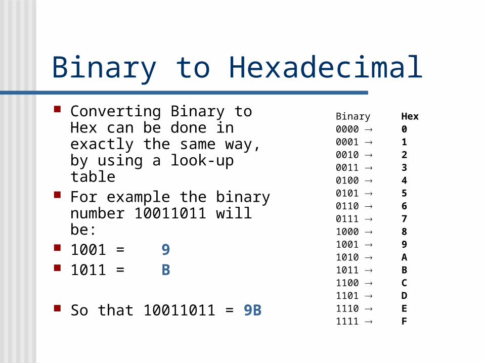
Binary to Hexadecimal Converting Binary to Hex
can be done in exactly the same way, by using a look-up table
For example the binary number 10011011 will be:
1001 = 9 1011 = B
So that 10011011 = 9B
Binary Hex0000 00001 10010 20011 30100 40101 50110 60111 71000 81001 91010 A1011 B1100 C1101 D1110 E1111 F

Activity 1
We will now review the answers to Exercise 2 pp 18-19,Nos 1,2,3 & 4.

Adding in Hexadecimal
289BC3 1
8 + B = 13
(i.e. nineteen written in hexadecimal)
8 + B = 13
(i.e. nineteen written in hexadecimal)
2 + 9 +1 = C
(i.e. twelve written in hexadecimal)
2 + 9 +1 = C
(i.e. twelve written in hexadecimal)
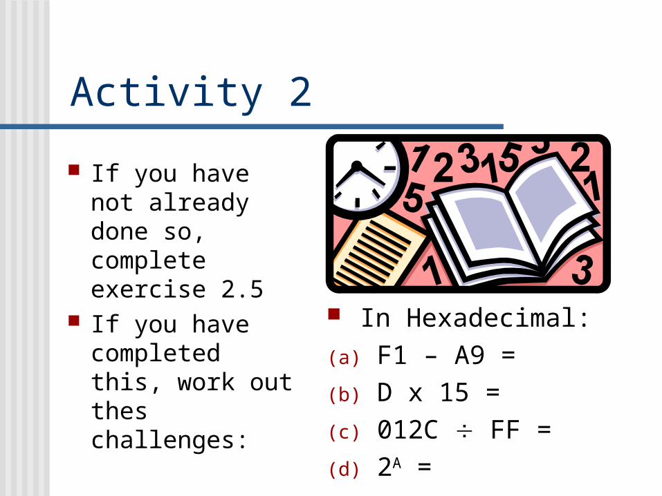
Activity 2
If you have not already done so, complete exercise 2.5
If you have completed this, work out thes challenges:
In Hexadecimal:(a) F1 – A9 = (b) D x 15 =(c) 012C FF =(d) 2A =

Processor Instructions

Diagram 3The CPU Level
RAM
Control Unit Registers
Arithmetic & Logic Unit
The most Important of the registers is the Accumulator (ACC)
ALL Data and Instructions must pass through the here.
The most Important of the registers is the Accumulator (ACC)
ALL Data and Instructions must pass through the here.
Near the control unit is the Program Counter (PC)
This indicates which instruction is currently being processed.
Near the control unit is the Program Counter (PC)
This indicates which instruction is currently being processed.
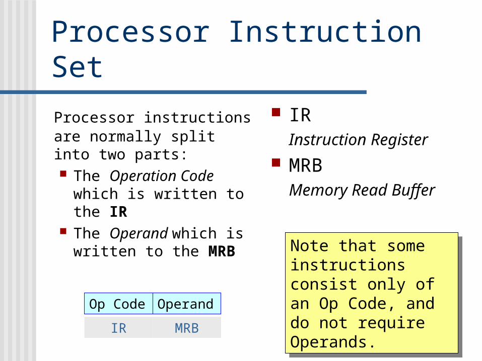
Processor Instruction Set
Processor instructions are normally split into two parts: The Operation Code
which is written to the IR
The Operand which is written to the MRB
IR Instruction Register
MRB Memory Read Buffer
Note that some instructions consist only of an Op Code, and do not require Operands.
Note that some instructions consist only of an Op Code, and do not require Operands.
Op Code Operand
IR MRB

Instruction Types
Instructions beginning STx These are instructions to STORE data at some
RAM Memory Location
Instructions beginning LDx These are instructions to LOAD Data into the
Accumulator Instructions beginning ADx These are instructions to ADD data to the
contents of the Accumulator

Instruction TypesInstructions ending xxI These instructions use the Immediately following
operand as the data
Instructions ending xxD These instructions use the operand as an
Address Directly to Access the data Instructions ending xxN These instructions use the operand as an
address iNdirectly, to locate the address where the data is to be found.

Instruction TypesInstructions not requiring an Operand:
IN This inputs data into the processor from an
external source
OUT This outputs data to the VDU STP This stops the processor.

Examples LDI 34
STD 25
ADN 43
Loads 34 Immediately into the Accumulator
Stores the contents of the accumulator at memory address 25
Finds memory address 43, there goes to the location specified there. Takes the data at this second location and adds it to the value in the accumulator

A Working Program (1)
00 LDI 08 STN01 15 09 1202 STD 10 STP03 12 11 0004 LDD 12 2205 13 13 3306 ADD 14 0107 14 15 78
Trace through this program to see what it does.
You will need to keep careful track both of the accumulator and of memory locations 11 to 15

Program Working
00 LDI 08 STN01 15 09 1202 STD 10 STP03 12 11 0004 LDD 12 2205 13 13 3306 ADD 14 0107 14 15 78
ACC: 15
RAM11 0012 2213 3314 0115 78
Load 15 immediately into the Accumulator
Load 15 immediately into the Accumulator

Program Working
00 LDI 08 STN01 15 09 1202 STD 10 STP03 12 11 0004 LDD 12 2205 13 13 3306 ADD 14 0107 14 15 78
ACC: 15
RAM11 0012 1513 3314 0115 78
Store the contents of the accumulator Directly at location 12
Store the contents of the accumulator Directly at location 12

Program Working
00 LDI 08 STN01 15 09 1202 STD 10 STP03 12 11 0004 LDD 12 2205 13 13 3306 ADD 14 0107 14 15 78
ACC: 33
RAM11 0012 1513 3314 0115 78
Load the accumulator Directly with the contents of location 13
Load the accumulator Directly with the contents of location 13

Program Working
00 LDI 08 STN01 15 09 1202 STD 10 STP03 12 11 0004 LDD 12 2205 13 13 3306 ADD 14 0107 14 15 78
ACC: 34
RAM11 0012 1513 3314 0115 78
Add the contents location 14 Directly to the Accumulator
Add the contents location 14 Directly to the Accumulator

Program Working
00 LDI 08 STN01 15 09 1202 STD 10 STP03 12 11 0004 LDD 12 2205 13 13 3306 ADD 14 0107 14 15 78
ACC: 34
RAM11 0012 1513 3314 0115 34
Store the contents of the accumulator inDirectly at the address specified by location 12
Store the contents of the accumulator inDirectly at the address specified by location 12

Program Working
00 LDI 08 STN01 15 09 1202 STD 10 STP03 12 11 0004 LDD 12 2205 13 13 3306 ADD 14 0107 14 15 78
ACC: 34
RAM11 0012 1513 3314 0115 34
Stop ProcessingStop Processing

Interpretation of the Instructions00 LDI * Load 15 into Accumulator01 1502 STD * Store Accumulator contents 03 12 directly at location 1204 LDD * Load Accumulator with contents of 05 13 location 1306 ADD * Add contents of Location 14 to07 14 Accumulator08 STN * Store contents of Accumulator at 09 12 address specified at location 1210 STP * Stop Processing

Working Program (2)00 LDD01 1102 ADD03 1104 STN05 1006 STN07 09 08 STP 09 25 10 0911 05
Interpret these instructions, and write them out fully.
Then execute the program, to see what effect it has on locations 9,10 and 11.
Interpret these instructions, and write them out fully.
Then execute the program, to see what effect it has on locations 9,10 and 11.

Full Interpretation (2)00 LDD * Load the contents of location 11 01 11 into the Accumulator02 ADD * Add contents of location 1103 11 to the Accumulator 04 STN * Store the contents of Accumulator 05 10 at address specified in location 1006 STN * Store the contents of Accumulator07 09 at address specified in location 908 STP * Stop Processing 09 10 10 1011 05

More InstructionsThese instructions all divert processing to different locations in RAM:
JMP xx The program counter changes to XX and processing
continues from there.
JZ xx If the Accumulator is Zero, the program counter changes
to xx and processing continues from there. JMI xx If the Accumulator is Negative, the program counter
changes to xx and continues processing from there.
These commands work by changing the value in the PC
These commands work by changing the value in the PC

Working Program (3)00 IN01 JZ02 0703 STD 04 1005 STP06 0007 JMP 08 00 09 STP10 27
Translate this program into full instructions,
Then execute the program, to see what effect it has.
Translate this program into full instructions,
Then execute the program, to see what effect it has.

Full Interpretation (3)00 IN * Input01 JZ * If Accumulator Zero,02 07 jump to location 7 03 STD * Store contents of Accumulator.04 10 directly at location 10. 05 STP * Stop06 00 --- No Command ---07 JMP * Jump immediately 08 00 to location 0009 STP * Stop Processing 10 ?? --- value is first non-zero input --
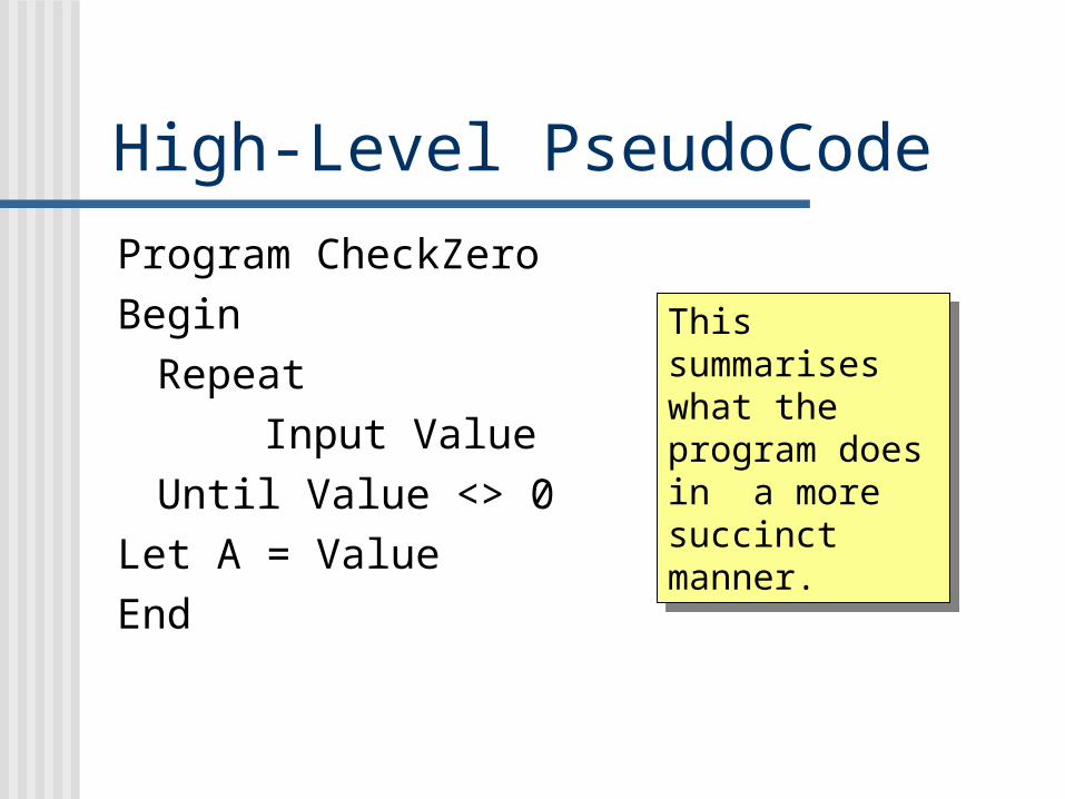
High-Level PseudoCode
Program CheckZeroBegin
RepeatInput Value
Until Value <> 0Let A = ValueEnd
This summarises what the program does in a more succinct manner.
This summarises what the program does in a more succinct manner.

PseudoCode Commands Program (name)
Begin do things
End
If (condition) Then
do thingsElse
do thingsEndif
For Count = 1 to X
do thingsEndFor
While (condition)do things
EndWhile
Write (number) Read (number) A: = (something)

Activity 3
Exercise 5 Page 19.
Attempt Parts 1 & 2

TOM
TotallyObedientMoron

What is TOM? First of all, TOM is a
CPU simulator which allows you to run short CPU programs and a lot more.
You need to access H:/Tomfile and download all the files in the folder to your A: drive.
Double-Click on TOM.exe and you will get this dialogue box.

RAM Memory Locations, where the program will be stored:
RAM Memory Locations, where the program will be stored:
Program Counter
Program Counter
AccumulatorAccumulator
Click-Able Keys to input, edit and clear Instructions.
Click-Able Keys to input, edit and clear Instructions.
Output DeviceOutput Device
Control ButtonsControl Buttons

Getting to know TOM Clicking ‘Help’ on the
toolbar brings up this screen. After this session you should spend some reading the first 6 sections.
Here we are going to dive straight in to the instruction Set (4th on the list)
TOM’s Instructions are very like (but not exactly the same as) the ones we have seen.
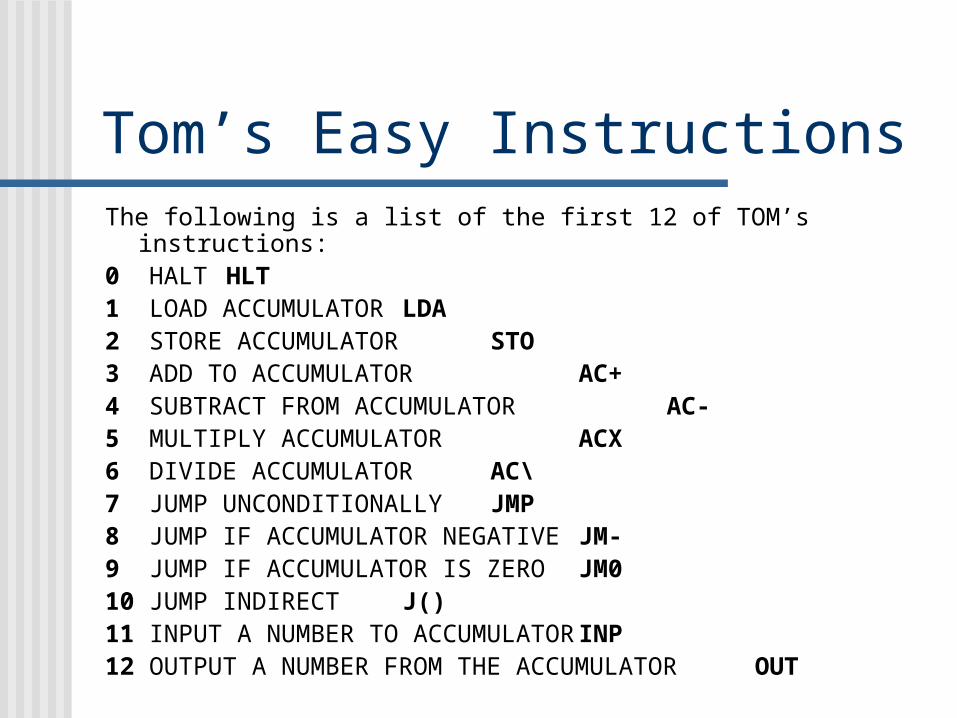
Tom’s Easy InstructionsThe following is a list of the first 12 of TOM’s instructions:0 HALT HLT1 LOAD ACCUMULATOR LDA2 STORE ACCUMULATOR STO3 ADD TO ACCUMULATOR AC+4 SUBTRACT FROM ACCUMULATOR AC-5 MULTIPLY ACCUMULATOR ACX6 DIVIDE ACCUMULATOR AC\7 JUMP UNCONDITIONALLY JMP8 JUMP IF ACCUMULATOR NEGATIVE JM-9 JUMP IF ACCUMULATOR IS ZERO JM010 JUMP INDIRECT J()11 INPUT A NUMBER TO ACCUMULATOR INP12 OUTPUT A NUMBER FROM THE ACCUMULATOR OUT

Our First TOM Program
At the top of the TOM window, click on:
File – Open
then select:
wexampl1.tom
from the menu.
At the top of the TOM window, click on:
File – Open
then select:
wexampl1.tom
from the menu.

TOM Example 100 LDA 2401 OUT02 HLT03040506070809101112131415
This is the disassembled version of the program. In order to see this, you should click on: Options – Disassemble
NB: Assembled =
“in Numerical form” Disassembled =
“In mnemonic code form
161718192021222324 5525262728293031

Running Example 1 Run the
Program. The yellow
highlight will move down the screen.
What else happens?
RUNRUN

Running Example 1
Program Counter shows 2
Program Counter shows 2
The program is now in Assembled form
The program is now in Assembled form
The value 55 has been printed out.
The value 55 has been printed out.
Accumulator shows 55
Accumulator shows 55
So, what exactly did the
program do?

What Example 1 Did:00 LDA 2401 OUT02 HLT03040506070809101112131415
Loaded the value 55 into the Accumulator, from location 24
Output the value in the Accumulator to the Printer
Stopped Processing.
161718192021222324 5525262728293031

TOM Example 200 1101 2 1202 1103 3 1204 1205 006070809101112 0 12131415
Load in Example 2, and use the assembled (left) or the disassembled version (right).
Say what effect each line will have.
Trace through the program to work out what exactly will happen.
Run the program to see if you were right.
00 INP01 STO 1202 INP03 AC+ 1204 OUT05 HLT06070809101112 HLT 12131415

TOM Example 2 Input a number from the Keypad
into the Accumulator Store the number at location 12 Add the number stored at
location 12 to the value in the Accumulator
Output the value in the Accumulator to the printer
Stop processing
00 INP01 STO 1202 INP03 AC+ 1204 OUT05 HLT06070809101112 HLT 12131415
The task performed by the program was to double the input number, and print out the answer.
The task performed by the program was to double the input number, and print out the answer.

TOM Challenge Try to create a program to
do the following: Input two numbers from the
Keypad into the Accumulator Store the numbers at
locations 12 and 13 Subtract the second number
entered from the first Output the answer Stop processing
00010203040506070809101112131415
Work on paper first.
When you feel that the program you have created is correct, then type it in and run it.
Work on paper first.
When you feel that the program you have created is correct, then type it in and run it.

TOM Challenge - solution
00 Input a number01 Store at location 1202 Input a number03 Store at location 1304 Load acc from location 1205 Subtract value from
location 13 from accumulator
06 Output the value in the accumulator
07 Halt
00 INP01 STO 1202 INP03 STO 1304 LDA 1205 AC- 1306 OUT07 HLT0809101112131415
00 1101 2 1202 1103 2 1304 1 1205 4 1306 1207 00809101112131415Disassembled
version
Disassembled version
Assembled versionAssembled version

Activity 4You should now open in turn, Examples 3, 4 and 5 from the disk. In each case you should:
1. Make a written copy of the program in disassembled form.
2. Explain what effect each line of the program will have
3. Trace through the program to see its effect on the accumulator, memory locations and output.
4. Run the program to see whether you are correct5. Briefly summarize what task the program is
performing.
We will start next week’s session with a review of these examples.
In addition, before next week’s session , you should read TOM’s Help File (the first 6 sections)
In addition, before next week’s session , you should read TOM’s Help File (the first 6 sections)