Embed Size (px)
Citation preview

Journal of Computer-Aided Materials Design, 7: 171–194, 2001.KLUWER/ESCOM© 2001 Kluwer Academic Publishers. Printed in the Netherlands.
Systems design of high performance stainless steels II. Prototypecharacterization
C.E. CAMPBELL∗ and G.B. OLSONDepartment of Materials Science and Engineering,Northwestern University, Evanston, IL 60208, U.S.A.(Tel: 847-491-5222; Fax: 847-491-7820)
Received and accepted 2 April 2000
Abstract. Within the framework of a systems approach, the design of a high performance stainless steel integratedprocessing/structure/property/performance relations with mechanistic computational models. Using multicom-ponent thermodynamic and diffusion software platforms, the models were integrated to design a carburizable,secondary-hardening, martensitic stainless steel for advanced gear and bearing applications. Prototype evalua-tion confirmed the predicted martensitic transformation temperature and the desired carburizing and temperingresponses, achieving a case hardness of Rc 64 in the secondary-hardened condition without case primary car-bides. Comparison with a commercial carburizing stainless steel demonstrated the advantage of avoiding primarycarbides to resist quench cracking associated with a martensitic start temperature gradient reversal. Based onanodic polarization measurements and salt-spray testing, the prototype composition exhibited superior corro-sion resistance in comparison to the 440C stainless bearing steel, which has a significantly higher alloy Crconcentration.
Keywords: materials design, carburizing, anodic polarization, dilatometry, secondary-hardening, fracture-toughness
1. Introduction
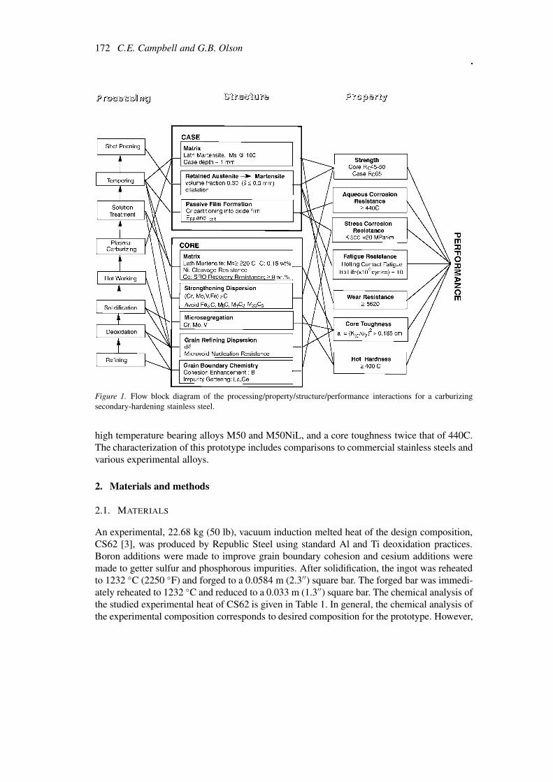
A systems approach [1] to computational materials design was used to design a prototypehigh-performance stainless bearing steel. The first three steps of system design – establish-ment of the property objectives, the model development, and integration and optimization ofthe design models – were described in Part I [2]. Figure 1 illustrates the interconnections be-tween the desired property objectives, structure, and processing for the design of a carburizingsecondary-hardening, martensitic stainless steel. The next step of the systems design approachis the characterization of the design composition to determine whether the desired propertyobjectives were obtained. Experimental evaluation of the design prototype also identifies thestrengths and weaknesses of the design models applied. That is, if the prototype does notmeet the required property objectives, then either the desired property objectives must bereevaluated or the design models must be improved.
This work describes the characterization of the prototype carburizing, secondary-hardening,martensitic stainless steel designed in Part I [2] and verifies whether the established propertyobjectives were obtained. These objectives include a lath martensitic microstructure obtainedwith a Ms temperature greater than 150 ◦C, a carburized case that has a surface hardnessexceeding Rc 62 and that does not include the formation of primary carbides, an aqueouscorrosion resistance exceeding that of 440C, a rolling contact fatigue resistance equilvalent to∗Now at NIST, Metallurgy Division, 100 Bureau Dr. Stop 8555, Gaithersburg, MD, 20899-8555, U.S.A.
172 C.E. Campbell and G.B. Olson
Figure 1. Flow block diagram of the processing/property/structure/performance interactions for a carburizingsecondary-hardening stainless steel.
high temperature bearing alloys M50 and M50NiL, and a core toughness twice that of 440C.The characterization of this prototype includes comparisons to commercial stainless steels andvarious experimental alloys.
2. Materials and methods
2.1. MATERIALS
An experimental, 22.68 kg (50 lb), vacuum induction melted heat of the design composition,CS62 [3], was produced by Republic Steel using standard Al and Ti deoxidation practices.Boron additions were made to improve grain boundary cohesion and cesium additions weremade to getter sulfur and phosphorous impurities. After solidification, the ingot was reheatedto 1232 ◦C (2250 ◦F) and forged to a 0.0584 m (2.3′′) square bar. The forged bar was immedi-ately reheated to 1232 ◦C and reduced to a 0.033 m (1.3′′) square bar. The chemical analysis ofthe studied experimental heat of CS62 is given in Table 1. In general, the chemical analysis ofthe experimental composition corresponds to desired composition for the prototype. However,

Systems design of high performance stainless steels, II 173
Table 1. Alloy compositions (wt.%)
Element Design AerMet100 AF1410 1605-8B NASA1 PyrowearPrototype 675(CS62)
Fe balance balance balance balance balance balanceCo 15.51 13.10 14.25 15.8 22.53 5.4Ni 1.56 11 10.5 4.88 8.48 2.6Cr 9.13 3.0 2.1 7.87 11.75 13.0Mo 0.002 1.18 1.05 1.5 0.3 1.8V 0.21 NA NA NA 0.25 0.6Si <0.0002 0.04 NA NA 0.01 0.4Mn 0.02 0.01 NA NA <0.01 0.65C 0.21 (core) 0.24 0.16 0.248 0.29 0.07 (core)Al 0.008 0.001 0.005 – – –B 0.0023 – – – – –Ce 0.015 – – – <0.001 –La – – – <0.001 –N 0.002 – – – – –O 0.005 – – – – –P 0.001 0.005 – – 0.005 –S 0.002 0.006 – – 0.003 –Ti 0.011 0.02 – – – –
the oxide content at 0.005 wt.% O and the aluminum content at 0.008 wt.% are higher thanexpected in comparison to other commercial alloys. These compositions deviations may havean adverse effect on the material properties, especially the fracture toughness.
In characterizing the design alloy, the performance of the prototype was compared to twoother alloys: the model secondary hardening steel 1605-8B [4] and the commercial carburiz-ing martensitic stainless steel, Pyrowear 675 [5]. The 1605-8B alloy was produced by NKKCorporation using vacuum induction processing. Carpenter Technology provided rod materialfrom an experimental heat of Pyrowear 675.
2.2. EXPERIMENTAL METHODS
Dilatometry was used to study the martensitic transformation using a computer controlleddilatometer. Cylindrical samples, 3 mm in diameter and 10 mm in length, were heated in aninduction furnace and were quenched using helium gas. The temperature was monitored by aPt-Pt10%Rh thermocouple spot welded directly to the sample surface. The dilatometry exper-iments were conducted under a vacuum of <10−2 Pa. The thermal expansion and contractionwere recorded as functions of temperature as the samples were heated at 500 ◦C/minute toa temperature above the austenitic finish temperature, Af , then held at this temperature for15 min, and finally quenched to room temperature. The austenitic and martensitic start (As ,Ms) temperatures were identified by the discontinuous length changes.
174 C.E. Campbell and G.B. Olson
Bulk and surface heat treatments were performed to produce the desired microstructures.The typical sample size for such treatments was a 0.0125 m cube. The solution treatmentswere performed with the material either encapsulated in quartz tubing or in an furnace back-filled with argon. Tempering to precipitate the strengthening dispersion was also performed inan inert environment. Using a hydrogen furnace, decarburizing experiments were conductedusing polished samples of dimensions 2.5 mm × 5 mm × 20 mm.
Macro-hardness measurements were made using a Rockwell C tester on samples polishedto a 600 grit finish. A Vickers indenter with a 100 g load was used to measure the micro-hardness on samples polished to a 1 µm finish.
Plane-strain fracture toughness testing was conducted following the ASTM standard E399[6] for KIC testing. The machined compact tension samples were oriented longitudinally withrespect to the forging axis and had a thickness of 1.27 cm (0.5 in). These samples werepolished to a 6 µm finish so that crack propagation could be observed during pre-cracking.Testing was performed using a servo-hydraulic load-frame machince with a digital controller.The load line displacement was obtained using a clip gauge, which has a gauge length of0.254 cm (0.1 inch) and a range of 0.381 cm (0.15 inch). The compact-tension samples werefatigue pre-cracked at 20 Hz frequency with a stress ratio (R ratio) of 0.1. The peak load wasestablished at 4.89 kN (1.1 kips) and maintained until crack initiation was detected. Followingpre-cracking, side grooves of a depth of 20% of the total width, were added to the samples.The side-grooved samples were then loaded at a cross-head speed of 0.0013 cm s−1 (0.0005inches s−1) until fracture occurred. Two samples were tested for each over-aged heat treatmentcondition.
Additional three-point bend measurements were made on subsize samples using a screw-driven machine. The dimensions of the subsized three point bend samples were determined bythe maximum decarburizing sample size. The corresponding dimensions of the samples were20 mm in length, 5 mm in width, and 2.5 mm in thickness. EDM was used to cut a starternotch, with a width of 0.025 mm and a length of 1.125 mm, at the center of the 20 mm ×2.5 mm face. These samples were fatigue pre-cracked at 10 Hz frequency at a stress ratio (Rratio) of 0.1. The samples were tested using a cross-head speed of 0.00083 cm s−1.
Optical and scanning electron microscopy (SEM) were employed to characterize the mi-crostructures. Optical microscopy determined the general microstructure and the grain size,as well as variations in microstructures produced by composition gradients. The samples werepolished a 1 µm surface finish. A sodium-metabisulfite etchant (167 ml H2O, 33 ml HCl, 0.5 gNa2S2O5) was used to revealed the martensitic structure within the prior-austenitic grains. A10% Nital etchant was used to investigate the carbide structures. The fracture surfaces werecharacterized using a cold field emission scanning electron microscope (cFEG-SEM) with aenergy dispersive spectroscopy (EDS) detector.
The corrosion behavior was evaluated using anodic polarization measurements. An elec-trode was soldered to the sample before mounting in epoxy. The exposed surface area waspolished to a 1 µm and measured. A computer controlled potentiostat was used to measurethe anodic polarization curves in derated solutions. For consistency with the previously ob-tained polarization data [7], the materials were tested in aqueous solutions of 1% sucrose(for conductivity) and 3.5% NaCl with pH = 7. The free corrosion potential was establishedby allowing the system to reach a steady-state conditions after sitting for 30 minutes. Theanodic potential was scanned at a sweep rate of 2 mV s−1 continuously recording potentialand current.
Systems design of high performance stainless steels, II 175
Salt-spray corrosion testing was conducted following the ASTM standard B117 [8]. Beforetesting, the samples were weighed to the nearest 0.0001 g and the exposed surface area wasmeasured. The samples were polished to a 600 grit finish and cleaned with acetone. Then thesamples were suspended in a fog chamber for a total of 48 h and were exposed to cycles ofalternating environmental conditions of 2 h at 20 ◦C with a 5% salt spray solution and then1 h dry heat at 30 ± 1 ◦C. After exposure, the samples were again weighed to determinea corrosion rate and the surface corrosion products were noted. The corrosion rate, R, iscalculated using the expression:
R = 8.76104w
mm yr−1, (1)
where w is the measured weight loss in g, ρ is the density of the specimen in g cm−3, a isthe surface area exposed in cm, and t is the exposure time in hours. The presented corrosionrates serve as a preliminary analysis of the corrosion behavior of the materials as only twodata points were collected for each sample.
3. Characterization of prototype (results)
The first step in evaluating the new alloy (CS62) was the characterization of the core materialto determine the correct processing conditions of the forged material. While the case materialproperties are more important than the core properties, the correct processing of the core mate-rial must be established before carburizing the material to evaluate the case material propertiesand processing conditions. To assist in the characterization of the prototype, the Thermo-Calc [9] and DICTRA [10] software programs helped correlate observed microstructures toprocessing and material properties and aided in process optimization.
3.1. CORE MATERIAL
The measurement of the Ms temperature is the first step in the core material evaluation.Dilatometry determined a Ms temperature of 291 ◦C ± 15 ◦C, and an As temperature of761 ◦C ± 10 ◦C. The temperature at which the free energy of the FCC phase equals thefree energy of the BCC phase, the T0 temperature, was calculated 16 degrees lower than theexperimental T0 of 521 ◦C. Figure 2 presents the recorded dilatometry curves, along with theoptical microscopy of the quenched microstructure revealing the desired martensitic struc-ture. In addtion, the observed microstructure showed no evidence of large segregation ratios,which would have resulted in bands of the martensitic laths corresponding to the compositionvariations.
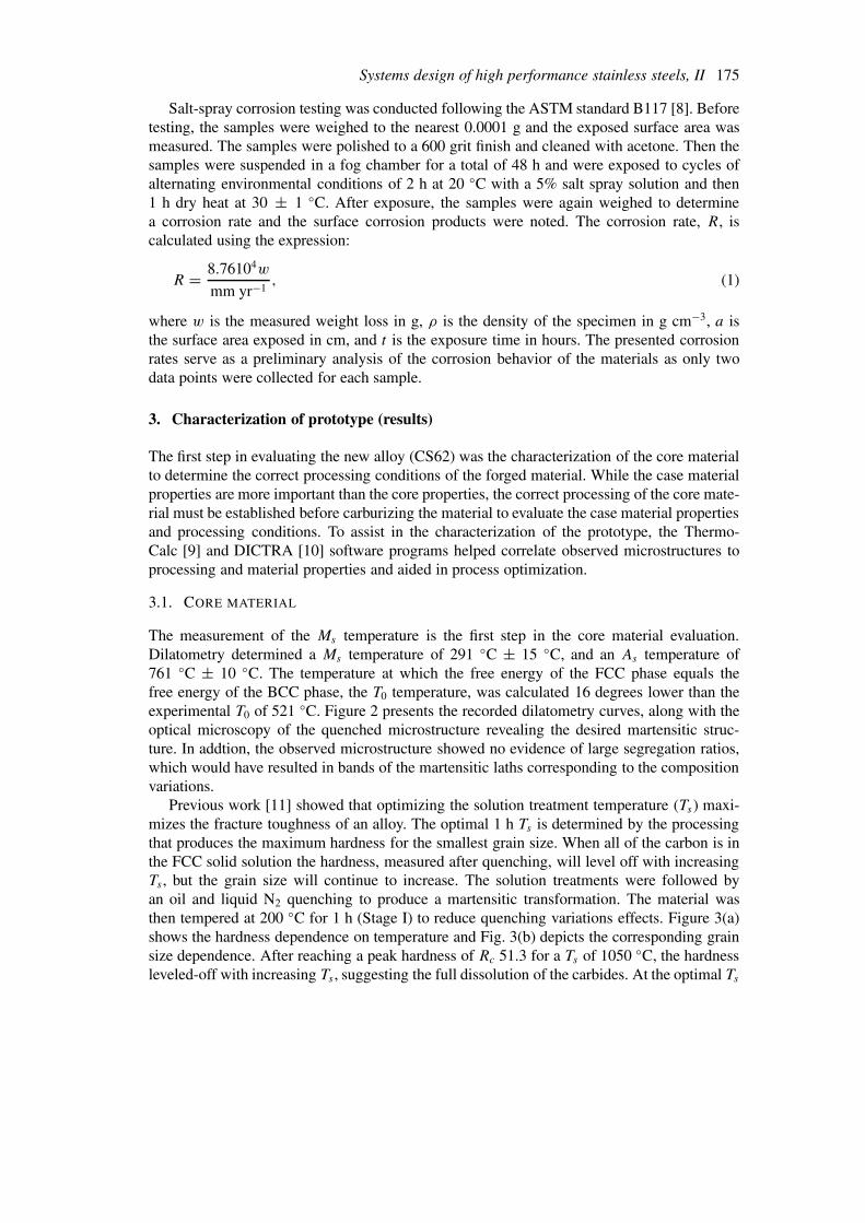
Previous work [11] showed that optimizing the solution treatment temperature (Ts) maxi-mizes the fracture toughness of an alloy. The optimal 1 h Ts is determined by the processingthat produces the maximum hardness for the smallest grain size. When all of the carbon is inthe FCC solid solution the hardness, measured after quenching, will level off with increasingTs , but the grain size will continue to increase. The solution treatments were followed byan oil and liquid N2 quenching to produce a martensitic transformation. The material wasthen tempered at 200 ◦C for 1 h (Stage I) to reduce quenching variations effects. Figure 3(a)shows the hardness dependence on temperature and Fig. 3(b) depicts the corresponding grainsize dependence. After reaching a peak hardness of Rc 51.3 for a Ts of 1050 ◦C, the hardnessleveled-off with increasing Ts , suggesting the full dissolution of the carbides. At the optimal Ts

176 C.E. Campbell and G.B. Olson
Figure 2. (a) Dilatometry curve representing the martensitc transformation. (b) Optical micrograph of the lathmartensitic microstructure produced upon quenching from a Ts of 1050 ◦C.
of 1050 ◦C, the grain size is 30 µm, using the mean linear intercept method. For comparison,the commercial carburizing stainless steel, Pyrowear 675, has a solution treatment of 1050 ◦Cfor 1.5 h and the prototype 1605-8B alloy has a solution treatment of 1050 ◦C for 1 h. Theoptimized solution treatment for CS62 is also similar to that of an earlier stainless prototype,NASA1, which had an optimized solution treatment of 1150 ◦C for 1 h. The higher optimalsolution temperature for the NASA1 alloy is attributed to its higher carbon (0.30 wt.% C) andvanadium contents (0.25 wt.% V) [7].
The secondary-hardening tempering response was investigated at three different temper-atures: 510 ◦C, 482 ◦C, and 450 ◦C. At 510 ◦C only monotonic softening was observed, asdemonstrated in Fig. 4. A broad peak hardness level at Rc 53.5 was observed at 482 ◦C. At450 ◦C, peak hardness was not established after 24 h of tempering. Consequently, 482 ◦C, theassumed tempering temperature in the design calculations [2], was confirmed as an acceptabletempering temperature.
The fracture toughness, determined by KIC testing, was characterized as a function oftempering time at 482 ◦C. Two slightly overaged conditions were chosen: 16 h and 22 h. Bothconditions failed to maintain stable crack growth during pre-cracking: unstable crack growthwas initiated after the fatigue pre-crack had grown to 75% of its desired length. Althougha valid KIC could not be ascertained for either the 16 h or 22 h tempered conditions, thefracture surfaces were evaluated to assess the fracture mechanisms and to estimate the tough-ness levels. The validity of the fracture surface evaluation to determine the active fracturemechanism in plane strain is based on the previous work developing the Stretch Zone Width(SZW) technique [12–14]. It was observed that the fracture surface just ahead of the SZW is
Systems design of high performance stainless steels, II 177
Figure 3. (a) Hardness as a function of solution temperature. (b) Grain size as a function of solution temperature.
Figure 4. Tempering response at 510 ◦C, 482 ◦C, and 450 ◦C.
indicative of the initial fracture mechanism under plane strain constraints. SEM examinationof the fracture surfaces, just beyond the fatigue pre-crack, reveal quasi-cleavage surfaces withsigns of intergranular embrittlement, Fig. 5. The intergranular facets have a diameter of ap-proximately 30 µm, which corresponded to the average grain size achieved after the 1050 ◦Csolution treatment.
The underlying brittle failure modes achieved using secondary-hardening conditions didnot meet the design objectives for the ductile fracture criteria. This was not completely unex-pected. As noted earlier the processing of the alloy was not as clean as desired, and the core

178 C.E. Campbell and G.B. Olson
Figure 5. SEM micrographs of the fracture surfaces observed after (a) 16 h and (b) 22 h of tempering at 482 ◦C.
composition was designed that the carbon content could be adjusted to achieve the desiredtoughness without significantly impacting the case microstructure design. Further investiga-tion of the fracture mechanisms as a function of heat treatment and composition was worthyof study to determine how future modeling efforts could be improved.
Evaluation of the fracture mechanisms as a function of heat treatment include investi-gation of the stage I tempering conditions. After tempering for 1 h at 200 ◦C, a KIC of68 ± 1.5 MPa
√m (62 ± 1.5 ksi
√in) at Rc 52 was measured and a ductile fracture surface
was observed, as seen in Fig. 6. This result at Rc 52, which is only 1 Rc point below thesecondary-hardening conditions examined, indicated that with a fine ε-carbide strengtheningdispersion the alloy has sufficient Ni content to resist cleavage fracture at room temperature.It should be noted in Fig. 6 that there are some large voids, approximately 25 µm in diameter,which can be attributed to oxide inclusions resulting from the higher than desired oxygencontent in the experimental heat.

Systems design of high performance stainless steels, II 179
Figure 6. SEM micrograph of the ductile fracture surface produced after tempering at 200 ◦C for 1 h.
Table 2. Heat treating conditions for the decarburized samples
Alloy Homogenization Solution Temperingtreatment
CS62 – 0 h NA 1050 ◦C 1h 200 ◦C 1 hCS62 8 h 1100 ◦C 10 h 1050 ◦C 1 h 510 ◦C 2 h
482 ◦C 6 hCS62 – 10 h 1050 ◦C 20 h 1100 ◦C 0.5 h 510 ◦C 2 h
482 ◦C 6 hCS62 – 20 h 1050 ◦C 20 h 1100 ◦C 0.5 h 510 ◦C 2 h
482 ◦C 6 h1605-8B 0 h NA 1050 ◦C 1h 200 ◦C 1 h1605-8B 8 h 1100 ◦C 10 h 1050 ◦C 1 h 510 ◦C 2 h
482 ◦C 6 h1605-8B 10 h 1050 ◦C 20 h 1100 ◦C 0.5 h 510 ◦C 1 h1605-8B 20 h 1050 ◦C 20 h 1100 ◦C 0.5 h 510 ◦C 1 h
The reduction in fracture-toughness associated with secondary-hardening is most likely theresult of the loss of grain boundary cohesion. Spaulding [15] evaluated the P and S segregationand decarburization embrittlement during secondary hardening of the 1605 model alloys anda prototype gear steel. The study concluded that the critical Griffith work for interfacial sepa-ration depended on the hardness level and demonstrated that ductile fracture modes could beobtained with reduced carbon levels. Thus, to determine the necessary reduction in alloy hard-ness to change the fracture mechanism in the secondary-hardened condition, decarburizationstudies were conducted.
Based on DICTRA simulations [16], decarburization experiments were performed on CS62and 1605-8B in wet hydrogen for 8 h, 10 h, and 20 h. Following decarburization, the finalvacuum homogenization treatments were also guided by DICTRA simulations. For the 8 h
180 C.E. Campbell and G.B. Olson
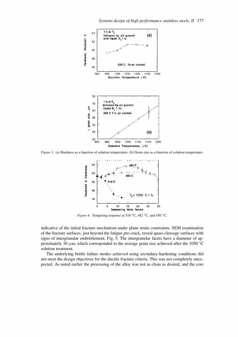
Figure 7. Fracture surface of CS1 decarburized for 20 h at 1100 ◦C (0.14 wt.% C).
decarburized samples, homogenization was completed at 1100 ◦C for 10 h. The 10 h and 20 hdecarburized samples were homogenized for 20 h at 1050 ◦C. Following solution treatmentand tempering (see Table 2 for specific conditions), the subsized 3-point bend samples werepre-cracked and fractured.
The results of the fracture testing were evaluated with the understanding that the fixedsubsized specimen geometry could result in varying crack tip stress states with decreasinghardness levels, making fracture analysis difficult. In addition to the constraints of the subsizespecimen geometry, the fracture-toughness analysis was limited by the higher than desiredoxide content. The following analysis is intended to provide a qualitative description of thefracture mechanisms present in the lower carbon version of the alloy. It is accepted that for thefixed sample geometry, as the crack grows in a ductile material the plastic zone may exceedthe sample width and plane strain conditions will not be maintained. However, the initial crackwill form under plane strain conditions, so that fractorgraphy at the beginning of stable crackgrowth will be representative of the initial acting fracture mechanism in plane strain.
After 8 h of decarburization, both CS62 (480 Vickers Hardness Number (VHN)) and 1605-8B (373 VHN) had quasi-cleavage fracture surfaces. Ten and 20 h of decarburization reducedthe carbon content of 1605-8B enough to produce a ductile fracture at less than 290 VHN.Unfortunately, 20 h of decarburization was not sufficient to produce a ductile fracture inCS62 with a 437 VHN. However, the fracture surface in Fig. 7 reveals some evidence of amore ductile fracture mode with little evidence of intergranular fracture. The microhardnessprofiles across the decarburized samples were measured and the strengthening model [17]was used to estimate the carbon level. The relatively flat hardness profiles indicated that thehomogenization treatments were successful. The hardness levels, estimated carbon contents,and estimated KIC values are given in Table 3.
Due to the small size of the samples, the estimated KIC values require scaling to betterrepresent values obtained from standard size samples. Using the work of Bergstrom [18]and calibrating the KIC measured on the original CS62 material with a standard thickness(KIC standard = 68 MPa
√m : KIC subsize = 132 MPa
√m), the experimental KQ values
were scaled using a factor of 0.5 to predict a more representative KIC estimate for screening

Systems design of high performance stainless steels, II 181
Table 3. Results of decarburization experiments
Alloy and Hardness Estimated Measured Estimatedcondition (VHN) C, wt.% KQ KIC MPa
√m
(h of decarb.)
CS62 – 0 h 590 0.21 132 66CS62 – 8 h 480 0.17 NA NACS62 – 10 h 473 0.17 NA NACS62 20 h 437 0.14 55.5 27.71605-8B – 0 h 585 0.24 124 62.11605-8B 8 h 373 0.10 87.4 43.61605-8B – 10 h 290 0.04 140 70∗
1605-8B – 20 h 287 0.04 122 61∗
∗Estimated value; unable to break samples using Sintech.
purposes. Figure 8(a) shows the measured hardness decreasing as a function of decarburizationtime. From Fig. 8, it is estimated that 45 h of decarburizing at 1100 ◦C is required to reducethe carbon level of the design composition to 0.05 wt.% C, and thus produce a ductile fracturecondition after secondary-hardening.
Combining the results of the various investigations of the fracture mechanisms resultingfrom secondary-hardening treatments, a mechanism map of the dominating fracture modesdefined by the carbon content and hardness was constructed, as seen in Fig. 9. The datarepresented on the map included the decarburization experiments on CS62 and 1605-8B andthe overaging experiments of CS62. The fracture map is divided into three regions. Above ahardness level of 525 VHN intergranular fracture dominates. Intergranular fracture also occursat low hardness levels, to the right of the line:
VHN = 1527 · (wt.%C) + 175. (2)
To the left of the intergranular boundary and between the hardness levels of 375 VHN and 575VHN is a region of quasi-cleavage. At hardness levels below 375 VHN and carbon contents tothe left of the intergranular boundary ( ≈< 0.10 wt.% C), ductile fracture mechanisms prevail.
The two regions of intergranular fracture indicate two different mechanisms. Intergranularfracture occurring at high carbon and hardness is represented by standard overaged temperingtreatments of 1605-8B and CS62. Spaulding’s work [15] showed that depletion of cohesion-enhancing C at the grain boundaries can cause for intergranular fracture at hardness levelsgreater than 450 VHN. The lower region of intergranular fracture is characterized by the longtime overaging experiments on CS62, where the segregation of P and S impurities is likely tobe the cause of the lost grain boundary cohesion.
The fracture mechanism map of Fig. 9 suggests that to achieve a ductile fracture modeusing secondary-hardening, the carbon content of the prototype composition must be de-creased to approximately 0.05 wt.% C. Such a lower carbon content alloy is currently underevaluation. The upper region of intergranular fracture indicates that fracture surface analysisof the grain boundaries is needed to determine if the boron additions, which were added toimprove grain-boundary cohesion, are present, or if boron was oxidized during processing.

182 C.E. Campbell and G.B. Olson
Figure 8. (a) Hardness as a function of decarburizing time a 1100 ◦C for alloys 1605-8B and CS62. (b) Alloycarbon content as a function of decarburizing time for CS62. Experimental carbon concentration estimates arecompared to the predictions of the DICTRA simulations for the plate and cylinder geometries.
3.2. CASE MATERIAL
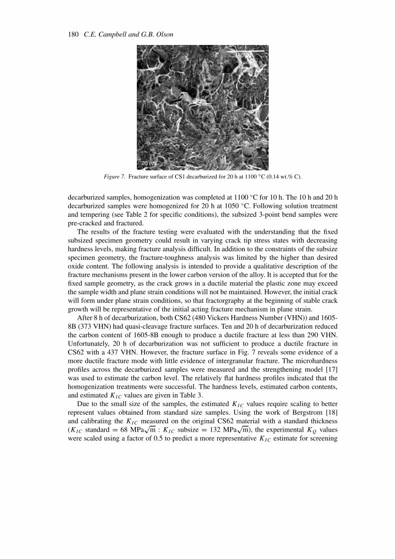
Optimal carburizing would produce 0.48 wt.% surface C with a 1 mm case depth. Usingindustrial gas-carburizing practices performed by Caterpillar Inc., pre-oxidation at 900 ◦Cwas followed by gas-carburizing for 5 h at 927 ◦C at nominal 1.0 surface carbon potential toproduce a 1.6 wt.% surface carbon with 1.5 mm case depth, as shown Fig. 10. The higher thannominal surface carbon content is predicted for the high Cr level. To produce a case withoutprimary carbides the surface carbon was reduced. The computed equilibrium carbon isoplethindicates that at 927 ◦C M7C3 carbides are present. The predicted carbon distributions in theFCC matrix at the carburizing and solution treatment temperatures are shown in Fig. 11 andthe corresponding phase fields are shown in Fig. 12.
Diffusion treatments were used to reduce the surface carbon and to dissolve the primarycarbides. DICTRA simulations were again used as a guide in determining the best treatment.At 1175 ◦C, the carbon solubility in the FCC phase is 0.7 wt.% C. Using the measured carbonprofile after carburizing and assuming an equilibrium spheroidal M7C3 carbide distribution,Fig. 13 presents the DICTRA simulations of the austenite carbon diffusion process at 1175 ◦Cin the two-phase field. The simulation predicts that after 2 h a 0.65 wt.% surface carbonlevel should be achieved and the primary carbides would be dissolved at equilibrium. Thisdiffusion step was performed followed by oil and liquid N2 quenching and a 200 ◦C 1 h temper.

Systems design of high performance stainless steels, II 183
Figure 9. Fracture mechanism map defining the region of intergranular, quasi-cleavage, and ductile fracture bythe carbon content and hardness. The fracture surfaces are representative of the different fracture modes.
Figure 10. Measured carbon profile after initial carburizing at 927 ◦C for 5 h at nominal 1.0 surface carbonpotential.
184 C.E. Campbell and G.B. Olson
Figure 11. Computed carbon distribution in matrix at 927 ◦C and 1175 ◦C assuming equilibrium with the M7C3carbide.
Figure 12. Carbon isopleth for CS62. Dashed lines denote the carburizing (Tc) and solution (Ts ) temperatures.
The resulting hardness profile with a surface hardness of 790 VHN is shown in Fig. 14(a).Figure 14(b) show the hardness profile after secondary hardening at 482 ◦C for 18 h andindicates a measured surface hardness of 816 VHN. Secondary hardening produced slightlyhigher case and core hardnesses. Both profiles show a large case depth (≈3 mm) due to thelong carbon diffusion step.
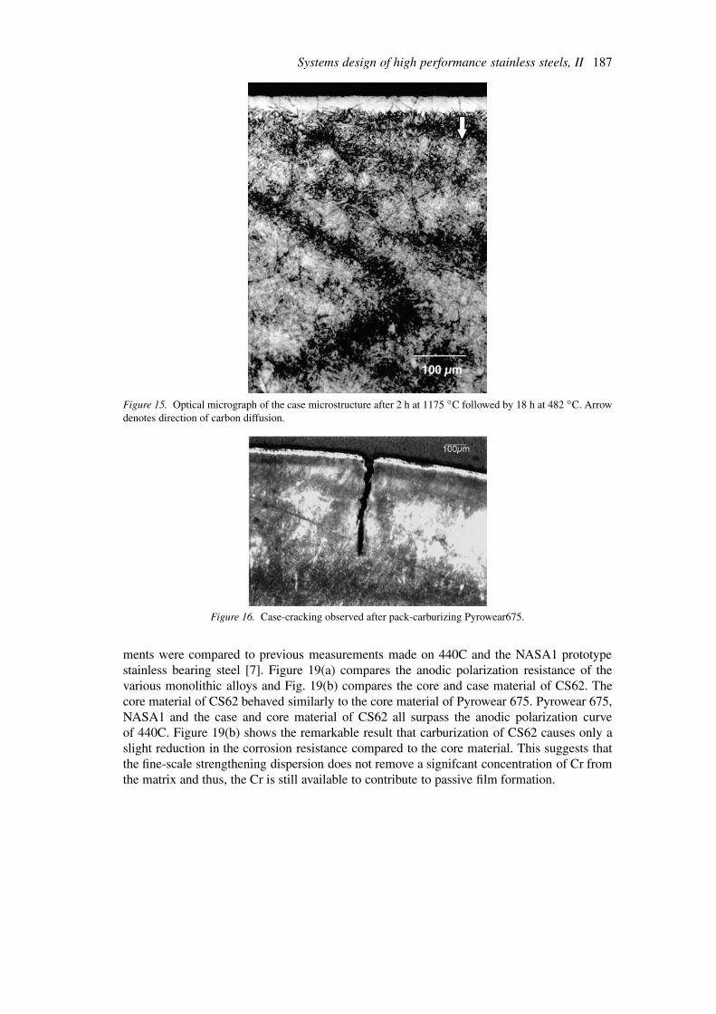
Optical microscopy of the case microstructure confirms a martensitic matrix, as seen inFig. 15. The amount of retained austenite and plate martensite increases toward the surface.Microscopy also shows the presence of some primary carbides (M7C3) in the first 250 µm ofthe case, indicating that equilibrium at 1175 ◦C was not fully established.
Although the measured case hardness met the original property objective, detailed analysisof the hardness and carbon profiles shows quantitative discrepancies with the design modelpredictions. A maximum hardness of 816 VHN is obtained at a case depth of 200 µm withthe presence of some primary carbides. The maximum hardness achieved without primarycarbides is 800 VHN at 300 µm. The DICTRA carburization simulation predicted a 0.625wt.% C composition at a case depth of 200 µm and 0.62 wt.% C composition at 300 µm.To evaluate the design strengthening model, the DICTRA simulations were used to determine

Systems design of high performance stainless steels, II 185
Figure 13. DICTRA simulation at 1175 ◦C for the diffusion of the carbon distribution produced after carburizingat 927 ◦C.
the case depth at which the design carbon content (0.48 wt.%) was obtained. The hardnessat this case depth of 1.25 mm is 775 VHN, 50 points below the design value of 825 VHN.The slightly lower than desired hardness can be attributed to the M2C driving force beinglower than the original target value, producing a larger M2C particle size with less efficientstrengthening.
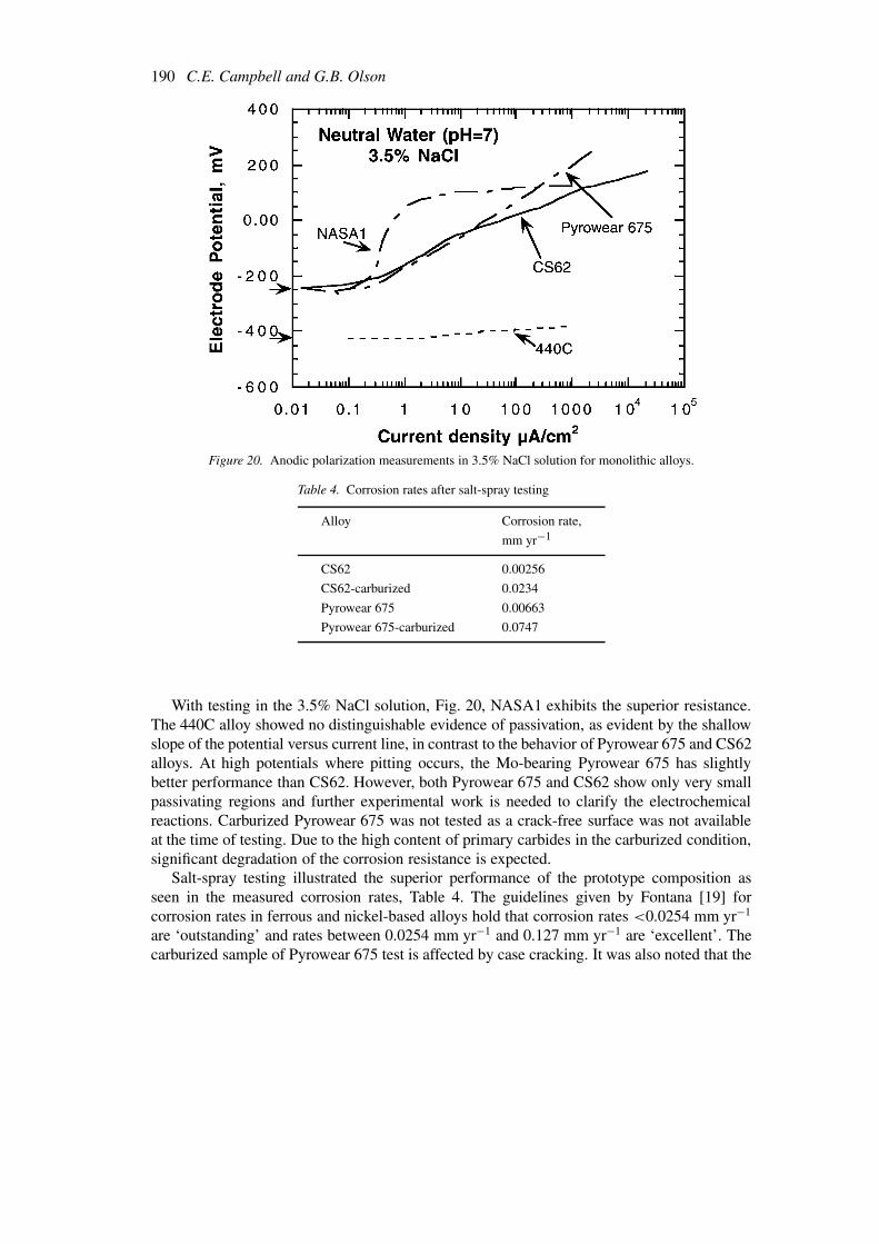
The fine size scale associated with the alloy M2C carbides precipitated during secondary-hardening should provide higher resistance to fatigue and wear corrosion compared to alloysthat use primary carbides as a strengthening dispersion. For comparison with such an alloy,the commercial Pyrowear 675 alloy was studied. Initial carburizing of the primary carbidestrengthened alloy using pack-carburizing highlights a large difference in alloy processability.Despite using various slow cooling methods from the recommended carburizing temperatureof 871 ◦C a crack-free surface could not be obtained, Fig. 16. Modeling indicates that thesurface cracks were generated from the residual tensile stresses produced by a Ms profile thatreverses directions with increasing carbon, Fig. 17(a). For comparison, the desirable montonicMs temperature profile for CS62 is shown in Fig. 17(b). For the Pyrowear 675 alloy, thecombination of low matrix carbon and high matrix Cr results in an increasing Ms temperatureas the carbon content increases. The additional alloy C from carburizing removes Cr fromthe matrix to form M7C3 carbides. This decrease of matrix Cr increases the Ms temperature.Figure 18 depicts the C isopleth of this primary carbide strengthened alloy and shows thatboth the carburizing and solutionizing temperatures correspond to multiphase regions.
Case cracking of the primary carbide strengthened alloy was avoided when a more con-trolled carburizing method was utilized. Gas-carburizing for 24 h at 871 ◦C at a nominal 0.7surface carbon potential, by MRC Bearing Corp., produced a crack-free case. Both carburizingprocesses were followed by the standard solutionizing (1050 ◦C for 1.5 h) and tempering(510 ◦C for 4 h) procedures for the alloy. This heat treatment and carburizing process produceda hardness of Rc 60 at case depth of 0.11 cm and a Rc 50 at 0.19 cm.
Anodic polarization measurements in 1% sucrose and 3.5% NaCl aqueous solutions weremade on the core material of Pyrowear 675 and CS62 and the carburized CS62. The measure-

186 C.E. Campbell and G.B. Olson
Figure 14. Hardness profiles after (a) after Stage I tempering at 200 ◦C for 1 h and (b) after secondary-hardeningat 482 ◦C for 18 h.
Systems design of high performance stainless steels, II 187
Figure 15. Optical micrograph of the case microstructure after 2 h at 1175 ◦C followed by 18 h at 482 ◦C. Arrowdenotes direction of carbon diffusion.
Figure 16. Case-cracking observed after pack-carburizing Pyrowear675.
ments were compared to previous measurements made on 440C and the NASA1 prototypestainless bearing steel [7]. Figure 19(a) compares the anodic polarization resistance of thevarious monolithic alloys and Fig. 19(b) compares the core and case material of CS62. Thecore material of CS62 behaved similarly to the core material of Pyrowear 675. Pyrowear 675,NASA1 and the case and core material of CS62 all surpass the anodic polarization curveof 440C. Figure 19(b) shows the remarkable result that carburization of CS62 causes only aslight reduction in the corrosion resistance compared to the core material. This suggests thatthe fine-scale strengthening dispersion does not remove a signifcant concentration of Cr fromthe matrix and thus, the Cr is still available to contribute to passive film formation.

188 C.E. Campbell and G.B. Olson
Figure 17. (a) Predicted Ms temperature distribution corresponding to the Pyrowear675 matrix carbon content atthe carburizing and solutionizing temperatures. (b) Predicted Ms temperature distribution for CS62 at the solutiontemperature of 1175 ◦C.
Figure 18. Computed carbon-isopleth for Pyrowear675. Dashed lines represent the carburizing (Tc) and solutionz-ing (Ts ) temperatures.

Systems design of high performance stainless steels, II 189
Figure 19. (a) Anodic polarization measurements in 1% sucrose solution for monolithic alloys and (b) comparisonof the behavior of the case and core material of CS62. The Ecorr values are represented by the open symbols whereo = CS62, ! = 440C, ( = Pyrowear 675 and ♦ = NASAI
190 C.E. Campbell and G.B. Olson
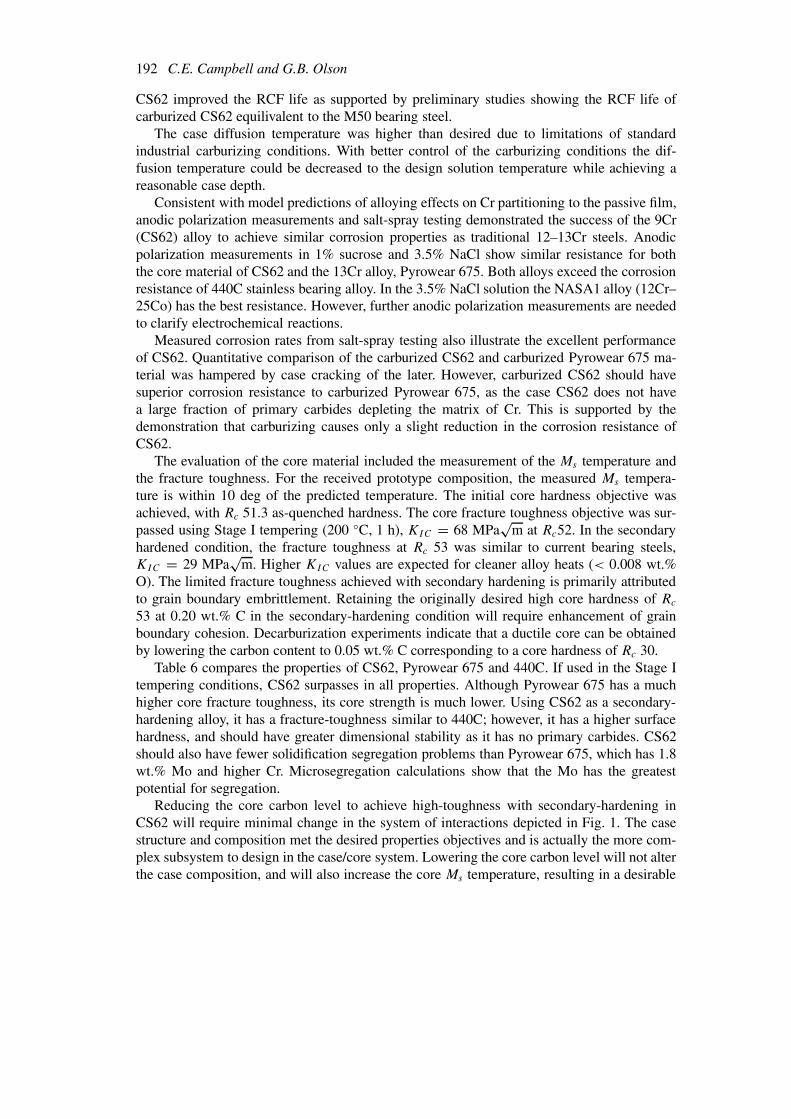
Figure 20. Anodic polarization measurements in 3.5% NaCl solution for monolithic alloys.
Table 4. Corrosion rates after salt-spray testing
Alloy Corrosion rate,mm yr−1
CS62 0.00256CS62-carburized 0.0234Pyrowear 675 0.00663Pyrowear 675-carburized 0.0747
With testing in the 3.5% NaCl solution, Fig. 20, NASA1 exhibits the superior resistance.The 440C alloy showed no distinguishable evidence of passivation, as evident by the shallowslope of the potential versus current line, in contrast to the behavior of Pyrowear 675 and CS62alloys. At high potentials where pitting occurs, the Mo-bearing Pyrowear 675 has slightlybetter performance than CS62. However, both Pyrowear 675 and CS62 show only very smallpassivating regions and further experimental work is needed to clarify the electrochemicalreactions. Carburized Pyrowear 675 was not tested as a crack-free surface was not availableat the time of testing. Due to the high content of primary carbides in the carburized condition,significant degradation of the corrosion resistance is expected.
Salt-spray testing illustrated the superior performance of the prototype composition asseen in the measured corrosion rates, Table 4. The guidelines given by Fontana [19] forcorrosion rates in ferrous and nickel-based alloys hold that corrosion rates <0.0254 mm yr−1
are ‘outstanding’ and rates between 0.0254 mm yr−1 and 0.127 mm yr−1 are ‘excellent’. Thecarburized sample of Pyrowear 675 test is affected by case cracking. It was also noted that the

Systems design of high performance stainless steels, II 191
Table 5. Predicted and measured properties of the prototype composition
Property Design Measured
Core PropertiesMs temperature, ◦C 300 291Hardness at 50% M2C completion 575 VHN (Rc ∼ 54) Rc 53.5Hardness stage I – Rc 52Solution temperature, ◦C – 1050grain size at Ts for 1 h 30 µmKIC MPa
√m 50 68 (Stage I)
29 (Stage IV)Corrosion rate, mm yr−1 – 0.0256
Case PropertiesMatrix structure martensitic martensiticHardness at 50% M2C completion 825 VHN 816 VHN Rc 64.5Hardness stage I – 800 VHN Rc 64Solution temperature, ◦C 1100 1175Corrosion rate, mm yr−1 <0.051 0.0234
surface of carburized Pyrowear 675 was covered with black oxide scale after testing. No suchscale was formed on the carburized CS62.
Initial rolling contact fatigue (RCF) testing using a 3 ball-on-rod method indicates that ata contact stress of 5.42 GPa (786 ksi) carburzied CS62 has a fatigue life equivalent to M50,a commerical high temperature monolithic bearing steel. Wells et al. [20] performed similarRCF testing using the same contact stress of 5.42 GPa and compared the M50 alloy to car-burised Pyrowear 675. With an optimal heat treatment, the B50 lifetime (Weibull distributionfor 50% accumulated failure) of Pyrowear 675 was five times greater than M50 .
4. Discussion
Using a systems approach to computational materials design, a carburizable, secondary-har-dening, martensitic stainless steel was designed, which meet all of the case material propertyobjectives, requires only thermal processing, and appears capable of meeting all of its prop-erty objectives. Establishing the desired property objectives, by analysis of existing bearing,secondary-hardening and stainless steels, a quantitative conceptual design was embodied bydeveloping and integrating design models for the martensitic transformation behavior, thecoherent M2C carbide precipitation strengthening, the formation and stability of passivatingoxide films, and the microsegregation occurring during solidification processing.
The design properties are compared to the measured properties in Table 5. A case surfacehardness of Rc 64.5 was obtained without the use of extensive primary carbides. The benefitof this microstructure was illustrated by the difficulty in processing the Pyrowear 675 alloy,which uses primary carbides to achieve its Rc 64 surface hardness. When pack-carburizing, theformation of primary carbides resulted in a tensile stress at the surface as the Ms temperaturedistribution was reversed. The martensitic case microstructure free of primary carbides in
192 C.E. Campbell and G.B. Olson
CS62 improved the RCF life as supported by preliminary studies showing the RCF life ofcarburized CS62 equilivalent to the M50 bearing steel.
The case diffusion temperature was higher than desired due to limitations of standardindustrial carburizing conditions. With better control of the carburizing conditions the dif-fusion temperature could be decreased to the design solution temperature while achieving areasonable case depth.
Consistent with model predictions of alloying effects on Cr partitioning to the passive film,anodic polarization measurements and salt-spray testing demonstrated the success of the 9Cr(CS62) alloy to achieve similar corrosion properties as traditional 12–13Cr steels. Anodicpolarization measurements in 1% sucrose and 3.5% NaCl show similar resistance for boththe core material of CS62 and the 13Cr alloy, Pyrowear 675. Both alloys exceed the corrosionresistance of 440C stainless bearing alloy. In the 3.5% NaCl solution the NASA1 alloy (12Cr–25Co) has the best resistance. However, further anodic polarization measurements are neededto clarify electrochemical reactions.
Measured corrosion rates from salt-spray testing also illustrate the excellent performanceof CS62. Quantitative comparison of the carburized CS62 and carburized Pyrowear 675 ma-terial was hampered by case cracking of the later. However, carburized CS62 should havesuperior corrosion resistance to carburized Pyrowear 675, as the case CS62 does not havea large fraction of primary carbides depleting the matrix of Cr. This is supported by thedemonstration that carburizing causes only a slight reduction in the corrosion resistance ofCS62.
The evaluation of the core material included the measurement of the Ms temperature andthe fracture toughness. For the received prototype composition, the measured Ms tempera-ture is within 10 deg of the predicted temperature. The initial core hardness objective wasachieved, with Rc 51.3 as-quenched hardness. The core fracture toughness objective was sur-passed using Stage I tempering (200 ◦C, 1 h), KIC = 68 MPa
√m at Rc52. In the secondary
hardened condition, the fracture toughness at Rc 53 was similar to current bearing steels,KIC = 29 MPa
√m. Higher KIC values are expected for cleaner alloy heats (< 0.008 wt.%
O). The limited fracture toughness achieved with secondary hardening is primarily attributedto grain boundary embrittlement. Retaining the originally desired high core hardness of Rc
53 at 0.20 wt.% C in the secondary-hardening condition will require enhancement of grainboundary cohesion. Decarburization experiments indicate that a ductile core can be obtainedby lowering the carbon content to 0.05 wt.% C corresponding to a core hardness of Rc 30.
Table 6 compares the properties of CS62, Pyrowear 675 and 440C. If used in the Stage Itempering conditions, CS62 surpasses in all properties. Although Pyrowear 675 has a muchhigher core fracture toughness, its core strength is much lower. Using CS62 as a secondary-hardening alloy, it has a fracture-toughness similar to 440C; however, it has a higher surfacehardness, and should have greater dimensional stability as it has no primary carbides. CS62should also have fewer solidification segregation problems than Pyrowear 675, which has 1.8wt.% Mo and higher Cr. Microsegregation calculations show that the Mo has the greatestpotential for segregation.
Reducing the core carbon level to achieve high-toughness with secondary-hardening inCS62 will require minimal change in the system of interactions depicted in Fig. 1. The casestructure and composition met the desired properties objectives and is actually the more com-plex subsystem to design in the case/core system. Lowering the core carbon level will not alterthe case composition, and will also increase the core Ms temperature, resulting in a desirable

Systems design of high performance stainless steels, II 193
Table 6. Properties of CS62, Pyrowear 675 and 440C
Property CS62 Pyrowear 675 440C(monolithic alloy)
Matrix Cr (wt.% ) 9 core/ 9 case 13 core/ 5 case 11 matrix / 17 alloyCore hardness, Rc 52 40 60Case hardness, Rc 64 64 60Core fracture 68 Stage I 150 20Toughness 29 Stage IVKIC (MPa
√m)
Predicted yCr in 0.75 0.64 0.54oxide filmCorrosion rate, mm yr−1 0.00256 (core) 0.00663 (core) NA
0.0234 (carb.) 0.0747 (carb)
steeper Ms gradient in the case. The processing of the alloy should remain the same, as thecase composition is unaltered.
While the models used were sufficient to design the current prototype, further modelingwork will improve the accuracy of the models and increase variety of design applications towhich the models can be applied. Current modeling of the martensitic transformation behavioremphasizes the prediction of the Ms temperature; however, future applications may requirecontrol of the martensitic morphology as well. For example, controlling the fraction of plateand lath martensite in the case of a carburized steel. Characterization of the design proto-type highlighted the need for improved modeling capabilities describing fracture toughness.These improvements are most likely to come from quantam mechanics modeling of impurity-induced embrittlment, which provide insights into the electronic bonding of various impuritiesat the grain boundaries, and the implementation of these results into a design process. Whilecurrent simplistic modeling of the aqueous corrosion resistance was sufficient for this appli-cation, a better understanding of the kinetic process is needed. Ideally, the aqueous corrosionmodeling should include the diffusion simulation of the growing passive film and indicatethe composition gradient in the passive film. As all of the models developed rely correlat-ing material properties and processing to thermodynamic quantities and diffusion reactions,all the modeling efforts are enhanced with improved thermodynamic and diffusion mobilityassessments.
5. Conclusions
By designing a case material which avoids the use of primary carbides and optimize thepartitioning of Cr into the passivating oxide films for corrosion resistance, a carburizing,secondary-hardening, martensitic stainless steel was developed that maintains the strengthlevels of the 440C composition while increasing the aqueous corrosion resistance and frac-ture toughness. Although the development of CS62 was a three year process based on twoprevious prototypes, an important output was the development of transferable process kineticand thermodynamic models. These models, defining the martensitic transformation behavior,
194 C.E. Campbell and G.B. Olson
the precipitation of the coherent M2C strengthening dispersion, the microsegregation resultingfrom solidification processing, and the passivation behavior of oxide films formed, can now beused to design high performance stainless steels to meet the specific property requirements ofa given application, as outlined in Part I [2] in the design objectives. The models developed arealso useful in the design of other high performance ferrous alloys, such as high-performanceaerospace gear steels. The same systems design strategy can also be applied to other materials,as already demonstrated by the design of case-hardenable polymer gears [21]. Thus, a systemsdesign approach provides an efficient and organized methodology for computational materi-als design requiring far fewer experimental prototypes. Once the required design models aredeveloped for a given system, the time and cost for alloy development can be greatly reduced.
Acknowledgements
This research was supported by a NSF Graduate Fellowship for CEC and was conductedas part of the multi-institutional Steel Research Group program. The authors thank Dr C. J.Kuehmann for assistance with the toughness and fatigue testing. Pyrowear675 was providedby Carpenter Technology. Alloy 1605-8B was produced by NKK Corporation, Japan. Gas-carburizing of the alloys was performed by Caterpillar Inc. and MRC Bearings Corp.
References
1. Jenkins, G.M., In Beishon, J. and Peters, G. (Eds.), Systems Behavior, Open University Press, Birmingham,UK, 1972, pp. 56–79.
2. Campbell, C.E. and Olson, G.B., J. Comput.-Aided Mat. Des, (2001)3. Kuehmann, C.J., Olson, G.B., Wise, J.P. and Campbell, C., Northwestern University, U. S. Patent,
#6,176.946, 2001.4. Kuehmann, C.J. and Olson, G.B., In Hawbolt, E.B. (Eds.), International Symposium on Phase Transfor-
mations During the Thermal Mechanical Processing of Steel - Honouring Professor Jack Kirkaldy, TheMetallugrical Society of the Canadian Institute of Mining Metallurgy and Petroleum, 1995, pp. 345–356.
5. CarTech, U.S. Patent 5,002,729, 1993.6. Annual Book of ASTM Standards, Vol. 03.01, ASTM, Philadelphia, PA, 1997, pp. 413–443.7. Stephenson, T.A., Campbell, C.E. and Olson, G.B., In Richmond, R.J. and Wu, S.T. (Eds.), Advanced Earth-
to-Orbit Propulsion Technology, NASA Conference Publication 3174, 1992, pp. 299–307.8. Annual Book of ASTM Standards, Vol. 02.05, ASTM, Philadelphia, PA, 1996, pp. 1–8.9. Sundman, B., Jansson, B. and Andersson, J.O., CALPHAD, 9 (1985) 153.
10. Borgenstam, A., Engström, A., Höglund, L. and Ågren, J., J. Phase Equilibria, 21 (2000) 269.11. Kuehmann, C.J., Doctoral dissertation, Northwestern University, 1994.12. Amouzouvi, K.F. and Bassim, M.N., Mater. Sci. Eng., 55 (1982) 257.13. Hoelzer, D.T., Ali, J.A. and Ebrahimi, F., Scr. Metall., 20 (1986) 1575.14. Srinivas, M., Kamat, S.V. and Rao, P.R., J. Testing and Evaluation, 22 (1994) 302.15. Spaulding, D., Doctoral dissertation, Northwestern University, Evanston, IL, 1995.16. Campbell, C.E., Doctoral dissertation, Northwestern University, Evanston, IL, 1997.17. Wise, J.P., Doctoral dissertation, Northwestern University, Evanston, IL, 1998.18. Bergstrom, D., Doctoral dissertation, Northwestern University, Evanston, IL, 1996.19. Fontana, M.G., Corrosion Engineering, McGraw-Hill, New York, 1986.20. Well, M.G.H., Beck, J.C., Middleton, R.M., Huang, P.J., and Wert, D.E., Surf. Engineer., 15 (1999) 321.21. D’Oyen, R., Doctoral dissertation, Northwestern University, Evanston, IL, 1997.


![Martensitic Stainless Steels - IJSER · PDF fileMartensitic Stainless Steels ... tempering temperature range for martensitic stainless steels is normally from 480. 0. C. [9] With in](https://img.dokumen.tips/doc/110x75/5a7685847f8b9aea3e8d537d/martensitic-stainless-steels-ijser-a-martensitic-stainless-steels-tempering.jpg)