Embed Size (px)
Citation preview

Basic Design for Safety
Principles
1

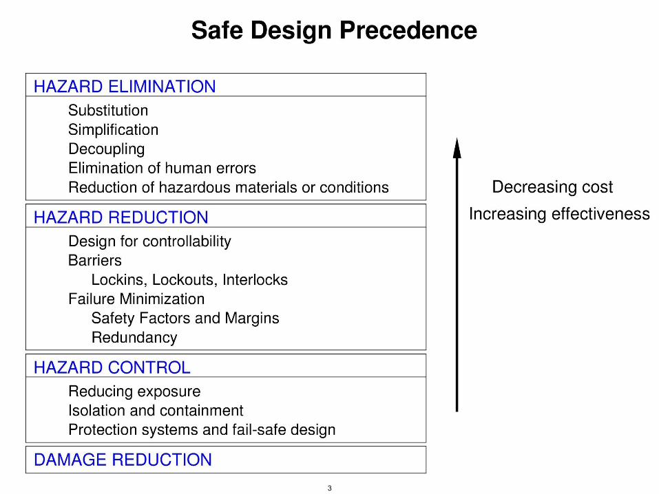
Designing to Prevent Accidents
• Standards and codes of practice contain lessons learned from the past
• Standard precedence
– Try to eliminate hazards from the design
– Identify causes of hazards and try to reduce their likelihood of occurring through design
– Control hazards once they occur
– Design to reduce damage
2
© Copyright Nancy Leveson, Aug. 2006 3
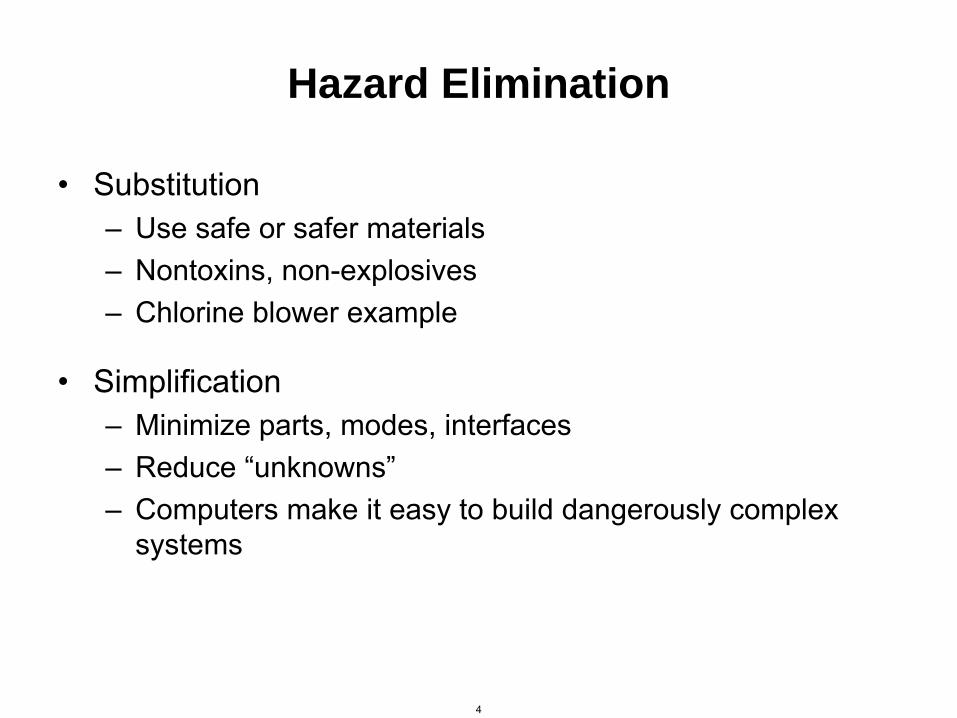
Hazard Elimination
• Substitution – Use safe or safer materials – Nontoxins, non-explosives – Chlorine blower example
• Simplification – Minimize parts, modes, interfaces – Reduce “unknowns” – Computers make it easy to build dangerously complex
systems
4
A cartoon from Rube Goldberg vs. the Machine Age by Reuben L. Goldberg is removed due to copyright restrictions.
5

Elimination (2)
• Decoupling: – Tightly coupled system is one that is highly interdependent – Coupling increases number of interfaces and leads to unplanned
interactions – Computers tend to increase system coupling unless very careful.
• Reduce opportunities for human error – Make impossible or possible to detect immediately
– Examples: wiring errors (color code, female/male connectors), typos, making displays readable, showing status of plant
• Reduce hazardous materials or conditions – Example: keep fewer hazardous chemicals on hand
6

Hazard Reduction
• Try to minimize likelihood of hazard occurring
7

Passive vs. Active Protection
• Passive safeguards: – Maintain safety by their presence – Fail into safe states
• Active safeguards: – Require hazard or condition to be detected and corrected
Tradeoffs – Passive rely on physical principles – Active depend on less reliable detection and recovery
mechanisms BUT
– Passive tend to be more restrictive in terms of design freedom and not always feasible to implement
8

Fail-Safe (Passive) Safeguards Examples
• Design so system fails into a safe state Examples:
– Deadman switch
– Magnetic latch on refrigerators
– Railroad semaphores: if cable breaks, fails into STOP position
– Cover over a high-energy source with circuit run through it
– Relays or valves designed to fail open or fail safe
– Air brakes: held in off position by air pressure. If line breaks, lose air pressure and brakes applied
– Early Apollo program: use free return trajectory. If engines failed at lunar orbit insertion, spacecraft safely coasts back to earth
9

More Examples
• Retractible landing gear: wheels drop and lock into position if system that raises and lowers them fails (e.g., pneumatic pressure system)
• Elevator: if hoist cables fail, safety mechanism wedges into guide rails
• Bathyscope: ballast held in place by magnets. If electrical power lost, ballast released and ascends to surface
• Railway signalling systems: signals not in use kept in “danger” position. Positive action required (setting signal to clear) is required before train can pass.
• Design cars so drivable with one flat tire. Also “run-flat tires” with solid rubber core
10
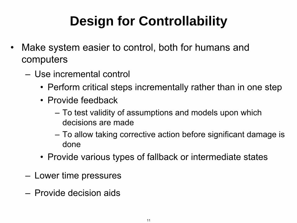
Design for Controllability
• Make system easier to control, both for humans and computers – Use incremental control
• Perform critical steps incrementally rather than in one step • Provide feedback
– To test validity of assumptions and models upon which decisions are made
– To allow taking corrective action before significant damage is done
• Provide various types of fallback or intermediate states
– Lower time pressures
– Provide decision aids
11

Monitoring
• To detect a problem need to – Check conditions that are assumed to indicate a potential
problem – Validate or refute assumptions made during design and analysis
• Can be used to indicate – Whether a specific condition exists – Whether a device ready for operation or operating satisfactorily – Whether required input is being provided – Whether a desired or undesired output is being generated – Whether a specific limit being exceeded or whether a measured
parameter is abnormal
• Need to design for checkability and inspectability
12

Monitoring (2)
• Two ways to detect equipment malfunction: – Monitor equipment performance (requires redundant info)
– Monitor equipment condition
• In general, monitors should – Detect problems as soon as possible
– Be independent from devices they are monitoring
– Add as little complexity to system as possible
– Be easy to maintain, check, and calibrate
– Be easily interpreted by operators (e.g., mark limits on dials)
13

Limitations of Monitoring
• Difficult to make monitors independent – Checks usually require access to information being
monitored, but usually involves possibility of corrupting that information
– Depends on assumptions about behavior of system and about errors that may or may not occur
• May be incorrect under certain conditions
• Common incorrect assumptions may be reflected both in design of monitor and devices being monitored.
14
Barriers
Lockout • Make access to dangerous state difficult or impossible
• Fences and physical barriers to block access to a dangerous condition (sharp blades, heated surfaces, high-voltage equipment)
• Logical barriers (authority limiting, software firewalls)
15

Barriers (2)
Lockin • Make it difficult or impossible to leave a safe state, maintain a
safe condition
• Possible uses: – Keep humans within an enclosure, e.g., seatbelts and
harnesses, doors on elevators
– Contain harmful products or byproducts, e.g., electromagnetic radiation, pressure, noise, toxins, ionizing radiation
– Contain potentially harmful objects, e.g., cages around an industrial robot in case it throws something
– Maintain a controlled environment (e.g., buildings, spacecraft, space suits, diving suits)
– Maintain a safe state (e.g. speed governors, relief valves to maintain pressure below dangerous levels)
16

Barriers (3)
Interlock
• Used to enforce a sequence of actions or events 1. Event A does not occur inadvertently 2. Event A does not occur while condition C exists 3. Event A occurs before event D
• (1) and (2) are called “inhibits”, (3) is a “sequencer”
• Examples: – Pressure sensitive mat or light curtain that shuts off a robot if someone
comes near
– Deadman switch – Guard gates and signals at railway crossings
17
Barriers (4)
• Examples (con’t): – Device on machinery to ensure all prestart conditions met, correct
startup sequence followed, conditions for transitions between phases are met
– Device to ensure correct sequencing of valve turn-off or turn-on or both not on or off at same time.
– Devices to preventing disarming a trip (protection) system unless certain conditions occur first or to prevent system from being left in disabled state after testing or maintenance
– Disabling car ignition unless automatic shift in PARK
– Freeze plug in a car’s engine cooling system (expansion will force plug out rather than crack cylinder if water in block freezes)
– Fusible plug in boiler becomes exposed if excessive heat and water level drops below predetermined level. Plug melts, opening permits steam to escape, reduces pressure in boiler, and prevents explosion.
18
Barriers (5) • Design Considerations for interlocks
– Design so hazardous functions stop if interlock fails
– If interlock brings something to a halt, provide status and alarm information to indicate which interlock failed.
– If use interlock during maintenance or testing, must preclude inadvertent interlock overrides or being left inoperative once system becomes operational again.
– When computers introduced, physical interlocks may be defeated or omitted. • Software programmers may not understand physical devices they are
replacing.
• May still need physical interlocks to protect against software errors.
• Make sure in safe state when resume operation, don’t just start from where left off.
Remember, the more complex the design, the more likely errors or hazards will be introduced by the protection facilities themselves.
19

Fault or Failure Tolerance
• Goal is to “tolerate” faults so they have no or little negative impact – Isolation or independence: so that misbehavior of one
component does not negatively affect behavior of another
– Failure warnings and indicators: to provide early detection of failures so preventive actions can be taken
– Carefully designed and practiced flight crew procedures to enable safe flight and landing when problems occur
– Design to tolerate human error
– Physical damage tolerance: ability to sustain damage without hazard resulting.
– Eliminate impact of common hardware failures on software
• E.g., do not use 1 or 0 to denote safe vs. armed
20

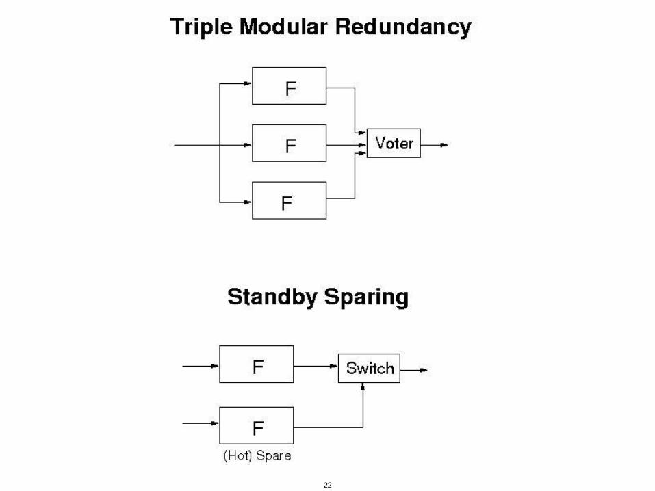
Redundancy
• Goal is to increase component reliability and reduce component failures
• Standby spares vs. concurrent use of multiple devices (with voting)
• Identical designs or intentionally different ones (diversity)
• Diversity must be carefully planned to reduce dependencies
• Can also introduce dependencies in maintenance, testing, repair
21
Redundancy
22

Redundancy (2)
• Identical designs or intentionally different ones (diversity)
• Diversity must be carefully planned to reduce dependencies
• Problem is potential lack of independence – Common mode failures: fail in same way, causes may be
different
– Common cause failure: Fail due to same cause
• Can also introduce dependencies in maintenance, testing, repair
23
Redundancy (3)
• Limitations – Common-cause and common-mode failures
– May add so much complexity that causes failures
– More likely to operate spuriously
– May lead to false confidence (Challenger)
– Extra costs including maintenance and extra weight
• Useful to reduce hardware failures. But what about software? – Ariane 5 loss
– Design redundancy vs. design diversity
– Bottom line: Claims that multiple version software will achieve ultra-high reliability levels are not supported by empirical data or theoretical models
24
Software Redundancy
• Software errors are design errors – Data redundancy: extra data for detecting errors:
e.g., parity bit and other codes checksums message sequence numbers duplicate pointers and other structural information
– Algorithmic redundancy: 1. Acceptance tests (hard to write) 2. Multiple versions with voting on results 3. Found to have lots of common faults
25

Software Recovery
• Backward – Assume can detect error before does any damage – Assume alternative will be more effective
• Forward – Robust data structures – Dynamically altering flow of control – Ignoring single cycle errors
• But real problem is detecting erroneous states
26

Example: Nuclear Detonation
• Safety depends on NOT working
• Three basic techniques (callled “positive measures”) 1. Isolation
– Separate critical elements 2. Inoperability
– Keep in inoperable state, e.g., remove ignition device or arming pin
3. Incompatibility – Detonation requires an unambiguous indication of human
intent be communicated to weapon – Protecting entire communication system against all credible
abnormal environments (including sabotage) not practical. – Instead, use unique signal of sufficient information
complexity that unlikely to be generated by an abnormal environment
27

Example: Nuclear Detonation (2)
• Unique signal discriminators must 1. Accept proper unique signal while rejecting spurious inputs 2. Have rejection logic that is highly immune to abnormal
environments 3. Provide predictable safe response to abnormal
environment 4. Be analyzable and testable
• Protect unique signal sources by barriers
• Removable barrier between these sources and communication channels
28

Example: Nuclear Detonation (3)
Image by MIT OpenCourseWare.
Barrier
Removablebarrier
Humanintent
Isolated component
Unique Signal Source
UQS Reader
Communications channelincompatible - Unique signal
Discriminator/Driver
Armingand firingvoltages
InclusionRegion
StoredUQS
Inoperable in abnormalenvironments
Isolated element
Exclusion Region
29

Example: Nuclear Detonation (4)
Intendedhumanaction
Stimuli Source Communication System
Uniquesignalno. 1
Uniquesignalno. 2
Armingsignal
Safing and FiringSystem
Intendedhumanaction
Intendedhumanaction
Human-machine interface
AABABBB
Arming andfusing system
Image by MIT OpenCourseWare.
30

Hazard Control
• Detect hazard and control it before damage occurs – May be able to reverse it before necessary environmental
conditions occur – Resources (physical and informational, such as diagnostics
and status information) may be needed to control hazard
• First need to detect hazard – Warning signals should be not present for too long or too
frequently (people become insensitive to constant stimuli)
• Do not assume hazard will never occur because of other protection devices or because software “never fails”
31

Hazard Control
LIMITING EXPOSURE (level or duration of hazard) – Stay in safe state as long and as much as possible
e.g., nitroglycerine used to be manufactured in a large batch reactor. Now made in small continuous reactor and residence time reduced from 2 hours to 2 minutes.
– Start out in safe state and require deliberate change to unsafe state
e.g., arm missile only when near target NPP shutdown software keeps variables in “trip” state and
requires change to non-trip.
– Critical conditions should not be complementary, e.g., absence of an arm condition should not be used to indicate system is unarmed
32

Hazard Control
ISOLATION AND CONTAINMENT
• Provide barriers between system and environment e.g., containment vessels and shields
• Isolate away from people: Very hard to maintain over time
PROTECTION SYSTEMS AND FAIL-SAFE DESIGN
• Move system to a safe or safer state – Requires existence of a safe state (shutdown in NPP, sleep state in
spacecraft cruise mode)
– Also requires an early warning with enough time between detection of hazard and actual loss event
33

Fail-Safe Design in Aviation
• Design integrity and quality
• Redundancy
• Isolation (so failure in one component does not affect another)
• Component reliability enhancement
• Failure indications (telling pilot a failure has occurred, may need to fly plane differently)
• Specified flight crew procedures
34
Fail-Safe Design in Aviation (2)
• Design for checkability and inspectability
• Failure containment
• Damage tolerance – Systems surrounding failures should be able to tolerate
them in case failure cannot be contained
• Designed failure paths – Direct high energy failure that cannot be tolerated or
contained to a safe path – E.g. use of structure “fuses” in pylons so engine will fall off
before it damages the structure
35
Protection Systems and Fail-Safe Design
• May have multiple safe states, depending on process conditions
• General rule is hazardous states should be hard to get into and safe states should be easy
• Typical protective equipment: – Gas detectors
– Emergency isolation valves
– Trips and alarms
– Relief valves and flare stacks
– Water curtains
– Firefighting equipment
– Nitrogen blanketing
36
Protection Systems and
Fail-Safe Design (2)
• Panic Button: stops a device quickly, perhaps by cutting off power
– Must be within reach when needed
– Operators must be trained to react quickly to unexpected events
• Passive devices better than active again
• Watchdog timer: Timer that system must keep restarting. If not then takes protective action
• Sanity checks (I’m alive signals): detects failure of computers
• Protection system should provide information about its control actions and status to operators or bystanders.
• Failure containment: limit effects of failure or hazard to local area
37
• Designed failure path: direct failure along a less critical path – Example: jet engine mounted on wing by a pylon structure. Severe
engine unbalance caused by loss of a number of fan blades from “foreign object ingestion” could destroy wing. But pylon and engine mount system designed to fail under these loads before main wing structure, allowing engine to fall harmlessly from airplane.
• The easier and faster is return of system to operational state, the less likely protection system will be purposely bypassed or turned off
• Try to control hazard while causing least damage in process
• May need to do more than simply shut down, e.g., blowing up an errant rocket. – Such facilities may do harm themselves, e.g., French weather balloon
emergency destruct facility, if inadvertently initiated
Protection Systems and
Fail-Safe Design (3)
38

Protection Systems and
Fail-Safe Design (4)
• May design various types of fallback states – e.g., traffic lights that fail to blinking red or yellow states, unstable
aircraft have analog backup devices because cannot be flown manually (but less functionality)
• Types of fallback states: – Partial shutdown (partial or degraded functionality)
– Hold (no functionality provided, but steps taken to maintain safety or limit amount of damage)
– Emergency shutdown (system shut down completely)
– Manually or externally controlled
– Restart (system in transitional state from non-normal to normal)
• Conditions under which each of fallback states should be invoked must be determined, along with how transitions between states will be implemented and controlled.
39
Protection Systems and
Fail-Safe Design (5)
• May need multiple types of shutdown procedures – Normal emergency stop (cut power from all circuits)
– Production stop (stop after current task completed)
– Protection stop (shut down immediately but not necessarily by cutting power from circuits, which could result in damage).
• If cannot design to fail into safe state or passively change to safe state, the hazard detectors must be of ultra-high reliability. – May add equipment to test detection system periodically by simulating
condition sensor is supposed to detect (e.g., challenge system)
– Challenge system must not obscure a real hazard and must be independent from monitor system
40
Protection Systems and
Fail-Safe Design (6)
• Hazard detection system may have three subsystems: – Sensor to detect hazardous condition
– Challenge subsystem to exercise and test sensor
– Monitor subsystem to watch for any interruption of challenge-and-response sequence.
• Note that complexity creeping up, decreasing probability these protection facilities will work when needed.
41
Damage Reduction
• In emergency, may not be time to assess situation, diagnose what is wrong, determine correct action, and then carry out action. – Need to prepare emergency procedures and practice them
– May need to determine a “point of no return” where recovery no longer possible or likely and should just try to minimize damage.
• Distinguish between warnings used for drills and those for real emergencies
• Damage minimization includes – Escape routes
– Safe abandonment of products and materials (e.g., hazardous waste disposal)
– Devices for limiting damage to people or equipment (e.g., blowout panels and frangible walls, collapsible steering columns on cars, sheer pins in motor-driven equipment
42
Design Modification and Maintenance
• Need to re-analyze safety for every proposed/implemented change
• Recording design rationale from beginning and traceability will help.
43

MIT OpenCourseWarehttps://ocw.mit.edu
16.63J / ESD.03J System SafetySpring 2016
For information about citing these materials or our Terms of Use, visit: https://ocw.mit.edu/terms.


![Safety Switches 8- Vol. 1, Ref. No. [0257] EnviroLine …. 1, Ref. No. [0257] EnviroLine/Upper Window 240V AC — 600V AC Heavy Duty, Fusible and Non-Fusible Single Throw with Upper](https://img.dokumen.tips/doc/110x75/5b1dfaa37f8b9a7e6d8b8dd2/safety-switches-8-vol-1-ref-no-0257-enviroline-1-ref-no-0257-envirolineupper.jpg)