Embed Size (px)
Citation preview

The Space Congress® Proceedings 1964 (1st) - Where Are We Going In Space?
Apr 1st, 8:00 AM
System Reliability Testing in Space Simulators System Reliability Testing in Space Simulators
Le Kratzer Supervisor of Orbital Simulator HIVOS, Reliability Testing Department, Lockheed Missiles & Space Company Sunnyvale, California
Vasily D. Prian Professor and Head of the Department of Mechanical Engineering, San Jose State College, San Jose, California
Follow this and additional works at: https://commons.erau.edu/space-congress-proceedings
Scholarly Commons Citation Scholarly Commons Citation Kratzer, Le and Prian, Vasily D., "System Reliability Testing in Space Simulators" (1964). The Space Congress® Proceedings. 1. https://commons.erau.edu/space-congress-proceedings/proceedings-1964-1st/session-2c/1
This Event is brought to you for free and open access by the Conferences at Scholarly Commons. It has been accepted for inclusion in The Space Congress® Proceedings by an authorized administrator of Scholarly Commons. For more information, please contact [email protected].

SYSTEM RELIABILITY TESTING IN SPACE SIMULATORS
Le Roy KratzerSupervisor of
Orbital Simulator HIVOSReliability Testing Department
Lockheed Missiles & Space CompanySunnyvale, California
Dr. Vasily D. Prian Professor and Head of the
Department of Mechanical Engineering San Jose State College San Jose, California
ABSTRACT
All too often the cost in time and money seriously limits the required testing programs. Scientific personnel accept the challenge of space craft design but are rarely stimulated to design and operate the required testing facilities. The space craft test engineer of today must, of necessity, be an experienced expert in all phases of space technology power-plants, solar arrays, hydraulics, pneumatics, structures, dynamics, ultra-high vacuum, solar effects, etc.
Today ! s space environmental testing procedures and techniques have developed a number of varied and specialized test facilities to insure system reliability of space craft. Of these many types, the most important and essential are the Orbital Simulators. The urgency of our current space efforts has been responsible for great strides in high vacuum equipment techniques and systems used for space simu lation.
To review briefly the state-of-the-art and to provide general familiarization with the reliability testing theory, methods and application of the Orbital Simu lator for space flights will be presented.
To make an over-all system reliability test, just before the launch—i.e., to find out exactly how the system will behave in orbit—space simulators are used.
INTRODUCTION
Man, on the threshold of free space flight travel, is realizing today a dream and a challenge that teve been present from the earliest recorded histories of time. The question of what lies out in the "heavens" will soon be answered by highly trained astronauts in advanced design space vehicles. However, before man can safely undertake such an adventure, numerous unmanned exploratory flights are re quired. These flights are expensive and failures cannot be tolerated. It has been well said, "We should not build junk yards in space." It is highly desirable to be sure in advance that the probability of a successful flight is very high. To a- chieve this objective requires mastery of almost endless problems and apparently insurmountable obstacles.
Today's space craft consists of a highly complex integration of intricate sub systems: guidance, propulsion, communication, power, etc. Not only must each sub-
195

system be tested to insure proper design, but the complete system must be tested when subjected to the expected combined environments. The old philosophy that a chain is no stronger than its weakest link is a principal axiom of today's relia bility testing engineer. The space simulator is a principal tool of the reliabili ty testing engineer. The simulator must be equipped with checkout equipment which in general is more advanced and of a higher operational reliability than the space vehicle to be tested.
SPACE SIMULATORS - THE OBJECTIVES
There are numerous environments in true space, such as ultra high vacuum, temp erature, radiation, gravity (or lack of it), meteoric showers, magnetic fields, etc. It is generally accepted that for space vehicles greater than four feet in diameter reproduction of ultra high vacuum and temperature is the most feasible approach. Unfortunately, the elimination and control of the gravitational field is beyond the existing "state-of-the-art" of a space simulator. However, the surfaces of the test specimen can be subjected separately to nuclear radiation, meteoric dust, so lar radiation, etc., to determine their effects.
The principal objectives of the space simulator chamber while subjecting the test specimen to the combined environments of high vacuum and heat flux are:
1. To obtain test data to assist in the determination of the Mean-Time-To-Fail ure and the principal failure modes of the space satellite.
2. To establish the degree of thermal compatibility of the test vehicle and its subsystems.
3« To determine the degradation of equipment when signals or voltages of the satellite have been deliberately changed.
4. To determine the degree and effects of outgassing and redeposition.
At the time of this writing, complete solar simulation is not feasible for a large test specimen for proper illumination, spectrum distribution, uniformity, and intensity have not been accomplished. The approach used at the Lockheed Missiles and Space Company at Sunnyvale, California, in the High Vacuum Orbital Simulator (HIVOS) is to provide a dependable, long-duration combined environment of high vacuum and a controllable heat flux. The heat flux is capable of providing both free space and earth orbital thermodynamic conditions.
SPACE SIMULATORS: DESIGN AND CAPABILITY
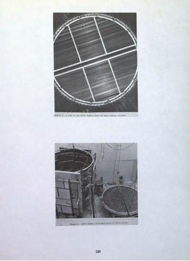
The HIVOS high-vacuum orbital simulator (1962) is Lockheed f s second generation space chamber. The "forefather," named High Altitude Temperature Simulator (HATS), was built in 1958. This chamber pioneered simulator technology dnd introduced into industry the first orbital simulator. The then existing vacuum technology state-of- the-art limited the vacuum to approximate only a 100-mile altitude and simulated the temperatures with radiant heating and refrigerating systems.
The HATS chamber (Figure 1) is constructed of stainless steel, 8 feet in dia meter and 9 feet high. The bottom of the chamber forms a door which is raised and lowered by a 10-jj inch diameter hydraulic lift capable of lifting 4000 Ibs. The pumping system consists of three diffusion pumps, a booster diffusion pump, a mech-
196

anical roughing pump. Use of liquid nitrogen-filled cold traps reduce the possibll- ity of oil vapor from the vacuum pumps backstreaming into the chamber. Temperaturer control during tests is obtained by using radiant and refrigeration systems within the chamber. There are 14 separate sectionsj each uses Freon 13 and Preen 22, in- dividually controlled.
Utilizing the experience gained in the design and operation of the EATS facility, Lockheed Missile and Space Company specified the operating parameters for the HIYOS facility (Figures 2,3, and 4).
The HITOS facility offers the following minimum capabilities!' —ft
1. High Vacuum (10~ Torr range) continuously for periods up to one year
2. Heat flux programmable to simulate noon to twilight orbits and even has re serve capacity to exceed the solar radiation experienced at Tenus
3. Cold-wall heat sink to near liguid nitrogen temperature (-293°F)
4* Automatic synchronous programming of test specimen operation
5- Random access programming of test specimen
6. Automatic data acquisition
7* Complete data processing facilities, including access to complex computers such as the IBM 7090 which are available in the Sunnyvale Complex.
The HITOS chamber measures 18 feet in diameter and 20 feet in length; it is bot- tom loading with a liquid nitrogen filled cold-wall composed of interlaced extruded *aluminum chevrons. The chevron surfaces facing the center of the chamber (Figure 5) have been sand blasted and anodized dark grey to improve their absorption of infra red radiation; the surfaces facing the inner walls of the chamber are polished to reflect radiated heat. Cold walls cover all the inside surfaces of the chamber (Figure 6). Liquid nitrogen at -320 F circulates through the hollow cold wall and removes all heat absorbed by the plates. The gaseous nitrogen which is boiled off by the absorbed heat is separated and vented to the atmosphere; the remaining li quid is returned to the storage tanks for reuse. Approximately 12,000 gallons are used each day when normal orbital simulation is programmed. There is a total of 2850 square feet of cold-wall surface area. The Heat Flux Simulator (Figures 7 aad 8) consists of clear quartz lamps with tungsten filaments and polished parabolic liquid-cooled aluminum reflectors. The lamp reflector assembly is designed to pro duce an even flux pattern over the specimen. Twenty-six separately controllable zones are used. Special radiometers measure the radiant heat flux programmed to the test specimen. A digital programmer (Figure 9) is used to provide any heat flux which may be required under orbital conditions: i.e., polar, equatorial, noon and twilight. The maximum output of the heat flux simulator is 800 BTU/ft /hour. The minimum output is less than 5 BTU/ft /hour. An automatic control panel (Figure 10) controls the operation of the twenty-two 36-inch liquid nitrogen trapped diffusion pumps, the four diffusion ejector pupps, and the four mechanical roughing pumps•
The chamber also has the capability of self-cleaning by bakeout, under vacua*, at a temperature of 400°F. This is accomplished by circulating special fluid through * grid of over two mile* of stainless steel tubing which is attached to the outside ef the ohastor (F±gw» 4)* A special bake-out chamber closure with a network of heat ing tubes attached is used instead of the normal test closure. The building aad pumping system were designed to permit the chamber length to be extended to 35
197

by removing the top of the chamber, installing an 18-foot diameter circular section 15 feet high, and rewelding the top section into place.
The existing pumping system is capable of producing a 10~ Torr pressure in 90 minutes; a 10-8 Torr pressure in 8 hours. A pressure of 1 x 10 Torr can be main tained with a calibrated leak of 150,000 micro-liters per second.
SPACE SIMULATORS: THEORY AND SPACE ENVIRONMENT
Satellites and space craft travel through space vacuum, except for the short duration of the ascent and re-entry phases; thus the only significant external mode of heat transfer is radiation. Within the vehicles, however, heat transfer takes place by radiation, conduction and, in pressurized vehicles, by forced convection. For satellites, the external sources of energy are the sun (insolation) and the earth which serves both as an emitter (earth emission) and as a reflector (albedo) of solar energy. An external surface segment of an orbiting satellite is small enough to be considered isothermal.
The governing mathematical relationship, which is derived in the appendix, (Eq. 6) can be expressed as follows:
This mathematical relationship fully expresses the physical model involved in the simulation of orbital satellites in space flights. Equation 6 indicates that the temperature history of the outer wall depends only on the time history of the external radiation absorbed by the vehicle in space and its surface properties. It is evident, too, that it is not necessary to evaluate the complex internal heat transfer terms that appear in the appendix (Equations 1 and 2).
To provide necessary controls for the simulator individual segments, it is ne cessary to program variation T wall temperature at the rates of as indicated in Equation 6. In the HATS chamber this variation could be done by a series of cam curves to be used for control of orbital temperatures. Thus, cams could be gener ated with the following assumptions and considerations:
1 . The orbital path is known
2. The orientation of the satellite is known
3- The satellite will receive radiation heat from two sources, i.e., earth and sun as presented above.
If the earth radiation and solar radiation are assumed constant, the total rad iant energy upon any point of the satellite depends on two conditions: how far the satellite is from the source of radiation and how it is oriented to the space from the source. It is essential to make cams for the segment controls so that the seg ments are maintained as close as possible to the actual temperature profiles. It might be added that the cam shape is reflected by the temperature limitation and the temperature response of the segments. Where compromise is necessary, the cam shape can be modified by the total amount of the radiant energy actually emitted from the segments which must be the same as the theoretical values calculated for each orbit.
Space environment simulation for large specimens such as would require the ser vices -of the HIVOS chamber may be achieved at present by high vacuum and either of198

two types of radiation source. These are solar simulation and thermal flux simu lation.
1. Solar Simulation: Complete solar simulation would include the entire elec tromagnetic radiation spectrum, but in current practice, consists only of the ultra violet, visible, and infra-red wavelengths. This is roughly equivalent to wave lengths from 2000 Angstrom units to 100,000 Angstrom units, with the energy peak at 4600 Angstrom units (Figure 11, Spectrum Distribution). Approximately 8 per cent of the radiation is in the ultra-violet range.
2. HIVOS Thermal Flux Simulation: The HIVOS simulator uses type TJ clear quartz lamps with tungsten filaments as a radiation source. The resulting spectrum extends approximately from 3800 Angstrom units to 100,000 Angstrom units, with the energy peak at about 11,500 Angstrom units. There is no significant amount of radi ation in the ultra-violet range; the major fraction is in the infra-red. By sequen tially switching the lamps and operating a minimum number with increased power, the average wavelength can be reduced.
The simulated radiation affects the specimen in two ways:
1. Degradation of skin surface (primary characteristic of ultra violet): This is insignificant as far as penetration of a metal skin is concerned, but of great importance in regard to the skin coating.
2. Thermal effects (primary characteristic of infra-red): The thermal energy penetrates the skin or outer surface and is transmitted throughout the specimen*
Heat flux simulation in the HIVOS vacuum chamber is produced by using quartz lamps. These lamps have shown remarkable reliability (not one has failed in ser vice luring the previous 20-month operation). The initial cost as well as the oper ating and maintenance cost for a quartz lamp system is moderate compared to solar types. For these reasons, a large number of lamps can be installed within the chamber and controlled to provide a simulated orbit.
Solar simulation equipment is extremely difficult to operate within a vacuum chamber. In order to simulate orbital conditions in facilities employing the car bon arc or mercury-xenon equipment, rotation of the specimen is usually required, which can become a costly and complex operation, particularly if many "hard-line" electrical connections with the specimen are required. Efforts to program solar simulation energy about the specimen become even more involved, usually requiring a large number of chamber optical penetration ports, elaborate reflective devices, or both. Duplication of equipment is generally necessary for prolonged test opera tions because of the unreliable performance of carbon-arc and mercury-xenon lamps and the frequent servicing required. That these problems are considerable is evi denced by the fact that not one installation is known to be capable, in operation, of providing the continuous service required for long-term large-scale reliability testing programs.
Where solar radiation is required because thermal equivalents of the shorter wavelengths will not suffice, it is often practical to expose relatively small sam ples to carbon arc or mercury-xenon lamp radiation in a small vacuum chamber.
Since only surface effects are to be considered, the large and complex equipment used for thermal simulation is not required.
A common approach to the problem of space vehicle temperature control involves the use of thermal control surfaces, which may be used to perform the following
199

functions:
1. To radiate heat generated internally in the vehicle.
2. To absorb solar radiation for the purpose of raising the internal tempera ture of the vehicle.
3. To perform both of the above functions simultaneously for different thermal requirements in several sections of the vehicle.
SPACE SIMULATOR: INSTRUMENTATION AND CONTROL SYSTEMS
The satellite vehicle being tested in HIVOS is under direct, precise control at all times during its simulated orbits.
The three automatic electronic systems test consoles located in the control room presently used for commanding the vehicle are:
1. Test Director f s Console
2. Programming and Synchronizing Timer (PAST)
3. Automatic Programmer and Test Systems (APATS)
Test Director's Console
This is equipped to control and monitor vehicle electrical power including solar battery simulation. Its most important functions, however, are to monitor and 5 if necessary, override the vehicle ! s internal orbital programmer, and to send program commands to the vehicle through hardlines. Although the console was built by HIVOS personnel for a specific test vehicle, it was designed to be easily adapted to any program configuration and to provide any desired degree of monitoring and control of the test specimen.
Programming and Synchronizing Timer (PAST)
The PAST has three functions:
1. Time base generation
2. Orbit number and orbit time display
3. Vehicle program commands—storage and transmission.
The time base is common to all vehicle control and monitoring operations in HIVOS and ties together the several data collection systems. Based on a 16 KG clock, it is accurate to 0.001^ per day.
The clock drives an orbital counter and timer which can be set to count simulat ed orbits with periods varying from 60 seconds to 999 minutes and 59 seconds. It can count up to 9999 orbits. The information is displayed for direct reading on two counters in the HIVOS control room and recorded in binary coded decimal form on oscillograph records.
The Programming and Synchronizing Timer can initiate predetermined time pulses which can trigger real time commands and stored program commands which are trans-
200

mitted to the vehicle at the proper time during the simulated orbit. The tape read er for this function is located in the Test Director's Console, where it is easily accessible during orbital operations.
Automatic Programmer and Test System (APATS)
The APATS was designed and built for HIVOS to program, control, monitor, and re cord test vehicle and payload functions and performance during simulated orbital flight (Figure 12). It consists of fifteen racks of power, telemetry, programming, signal distribution, and recording equipment.
Programming. A punched tape reader provides the selection and timing of all comparison and evaluation measurements of the test specimen operation. It is cap able of programming the selection of stimuli, selecting test points to be monitored, and determining program continuation in accordance with the measurements and evalu ation results.
Control. Control of the test vehicle is through the UHP command link coaxial cable. Preprogrammed coded instructions are transmitted to the vehicle by the APATS telemetry console whenever it is commanded by the Program and Synchronizing Timer to initiate various orbital events.
Monitoring and Recording. The APATS contains recorders for the optimum handling of the several types of data obtained from the test vehicle in the HIVOS chamber, as follows:
1. A magnetic tape recorder
2. A high speed (20 points per second) paper tape printer for hardline vehicle data, such as temperatures, voltage, etc.
J. A low speed (5 points per second) paper tape printer. Any data channels can be selected and sampled, as described.
4. An oscilloscope and camera are available for photographically recording transient data which is of too short duration for a printer or oscillograph.
5. Important TLM calibration signals can be displayed on a digital voltmeter if required.
6. Pour 20-channels event recorders are used for recording coded commands trans mitted to the vehicle, both Real Time Commands (RTC ! s) and Stored Program Commands (SPC's).
7. Oscillographs are used for recording general vehicle performance parameters, either continuously for backup diagnostic purposes or periodically during selected simulated orbits for status monitoring. Pour recorders provide 144 channels.
In addition to the several data recording devices incorporated in the APATS e- quipment, HIVOS capability includes a Low Speed Data System (LOSDAS). This equip ment is basically a specimen temperature recording system which can sample thermo couples at the rate of two per second. The readings can be printed on either print ed paper tape or punched cards or displayed for visual inspection. In addition, continuous analog data can be recorded on oscillographs. The equipment consists of two parallel 250 channel systems, one of which incorporates thermocouple refer ence junctions. The capacity of the LOSDAS is therefore 500 data channels, includ-
201

ing 250 temperature measurements. A patch panel is used to select from 606 possible inputs from the test chamber*
THE ORBITAL SIMULATOR; TEST PROGRAMMING AM) TEST CASE STUDIES
From experience, a practical, economical vehicle checkout and environmental test procedure has evolved. The procedure is divided into two parts, as follows:
Preparation
1• Test specimen assembled and subsystems checked
2. Instrumentation installed
3. Integrated systems test
4« Where possible, components are disassembled, cleaned, reassembled and in stalled on chamber door.
5« Chamber bake-out, if required, with blank chamber door
6. Final integrated systems test
7. Simulated orbital program during which all major events are programmed. Used as a final check for control data.
8. Test specimen installed in chamber and vacuum and data systems checked.
Operation
1. Simulate orbital program during which all major events are programmed. Used as a final check and control.
2. Pump down to minimum pressure (value depending upon the out-gassing rate of test vehicle.).
3. Repeat simulated orbital program during which all major events are programmed.
4. Check thermal simulation system.
5« Conduct simulated orbit test.
6. Remove test specimen from chamber and repeat simulated orbital program for control data and degradation information.
7» Check subsystems as required.
8. Analyze data and prepare reports.
Agena Life Test—Case Study I
Recently a nine-month reliability testing program using the High Vacuum Orbital Simulator (HIVOS) was completed (Figure 13). This program included three 30-day tests and one 45-d.ay test, subjecting the Agena flight vehicle to the combined en vironments of high vacuum and orbital temperatures. The vehicle was programmed as
202

if in orbit. All vehicle subsystems, guidance, communication, payload, power supply, etc., were operated normally. Vehicle motion was simulated by the injection of er ror signals into the guidance loop. The response was carefully observed. Over 200 thermocouples were used to monitor and record the temperatures. The operation of the subsystem was monitored by strip chart recorders and automatic testing equipment which are part of the HIVOS Automatic Data Acquisition Equipment.
Degradation of equipment operation was determined. Catastrophic failures were also discovered. Necessary steps were taken to correct the weaknesses.
Fuel Dump—Case Study II
Fuel and other liquids must frequently be discharged from the vehicle into space. It is desirable that this discharge take place without imposing any unwanted torques or thrust to the vehicle. Also, the surface of the vehicle may be coated with solar cells or special thermodynamic finishes which are subject to serious degradation if exterior contamination occurs, as would occur, if these liquids contacted the sur face. A test program was conducted in the HIVOS facility to determine if liquids similar to the Agena propellants (normally dumped upon completion of all ignition) would form jets wit! semi-vortex angles greater than 50°. If jets greater than 57° occur, then impingement on adjacent hardware transpires. Pour different liquids were used, Methyl alcohol, water, Methylene chloride and Freon -JOO.
These liquids were selected because they would not contaminate the chamber and they have different freezing points and molecular weights. Complete photographic coverage was provided. The motion pictures definitely showed that for water the liquid jets had half-cone angles in excess of 57° •
During some of the tests a heated flat plate, simulating an adjacent main nozzle extension, had pressure transducers mounted. The pressures indicated by these transducers varied with changes of the plate surface temperature. This confirms the possibility that liquid droplets do impinge on the vehicle and the subsequent evaporation can produce vehicle perturbations.
During these tests liquid at the rate of one pound per second and a duration of 50 seconds was emitted into the chamber.
The actual pressure during the dumping of the fluid could not toe measured because the vapor created erroneous readings of the ion gauges. Prior to the injection the pressure in the chamber was in the 10~6 Torr range and recovery occurred within minutes.
Thermal Stress of Agena Booster Adapter—Case Study III
A newly designed booster adapter section of the Agena vehicle was subjected to a constant temperature test of 200°F for four hour periods (Figure 14).
During the temperature soak strain gauges previously located on the vehicle pro vided information which enabled the design and fabrication engineers to verify their design integrity.
In addition, transducers which will provide inputs to the environmental telemetry during flight were calibrated, thereby insuring the acquisition of accurate flight information. The most economical way of obtaining this environment was to encase the booster adapter section completely with a uniform heat flux as obtained using the HIVOS heat flux simulator.
203

The space simulator of today can provide dependable long duration testing at low pressures with accurately controlled heat flux programming for thermal simulation. These facilities provide the design, integrity, and reliability testing information urgently needed for the space vehicles of today and tomorrow. Unfortunately, the schedules and budgets of some apace systems do not permit sufficient testing to be performed so that design discrepancies can be uncovered and modifications incorpor ated prior to launch. It is hoped that perhaps this article may stimulate the en gineers and scientists of the future to incorporate the philosophy of simulated en vironmental testing and provide sufficient time to incorporate adequate testing.
The space simulator should also be considered as a research and development tool to perform special tests associated with the performance of materials in space.
The design of space chambers of tomorrow will require additional operation para meters—larger size, capable of testing vehicles at least 24 feet in diameter and 50 feet high; high vacuum; safe accessibility for human entrance; solar simulation; rapid pump-down to simulate vehicle ascent; vibration for engine environment, etc.
Future simulators may require double-wall design and ion pumps (such as the new 50,000 cubic ft/sec Ultec Pump). •
The challenge to the designer is tremendous. For example, where human entry is required, the chamber must be so designed that in case of an emergency a man can be removed from the chamber and placed in an interlock where medical attendants can provide assistance, within 60 seconds. Since all doors must be vacuum tight, new designs and techniques need to be developed. At present a solar simulator of pro per size, uniformity and intensity is beyond the existing state-of-the-art. This challenge is one of many which has yet to be overcome.
APPENDIX
Mathematical Derivations
The equation governing the instantaneous heat balance on an element of vehicle skin in orbit can be written as:
WCpfr = *a S «e + I* H «H + FE E<*E -*T4 + pt +(it/
where
W is the weight of the element,
c is specific heat,
dT— is the rate of the tenpezature change,GLX
P S of is absorbed insolation* " -s s f
PD Re*' is the absorbed earth, reflection,K K
F.n E o< is the absorbed earth emission.,£j . Ci
d~£ T is the radiation emitted in space,
204

P represents heat power generated by the internal equipment,
Q, , is the heat being conducted along the wall to the element under con- cond sideration,
Q is the heat radiation from other internal members to the element. cross
In the Orbital Simulator, the heat balance equation on the same element can be written as:
W c f| = <rf (T 4 - T4) + P^ + Q ,, + Q (2) p dt J v w ' t cond cross v '
where
T is the test specimen wall temperature ,
3? is the geometrical factor between the chamber wall and the specimen skin element under consideration,
The remaining terms are identical to those in Equation (l). Exact temperature simulation requires that at any time the solution of Equation (2) is identical with that of Equation (l); i.e.,
Qcond +Q * Fg S ^ + FR R<*R+ P
. (3)
For a thermal test model identical to the flight vehicle, the terms defining the internal heat transfer are identical in both cases. Thus,
crf(Tw4 - T4) = Fs Sc*s + PR RC^ ,+ PE E E - (T£T4 . (4)
If Equation (4) can be satis t if ed, the internal and external temperature historywill be identical to the test flight. It might be pointed out that factor canbe made equal to the emissivity . Factor is given by
For concentric surfaces, if we make ^ equal to 1 (black body) , then the Equa tion (5) will reduce to ,
Therefore, Equation (4) can be written
. (6)
205

*•$ taf
m tr*
o

OL LU CO ^
U
r-18'
15 1/2'
11 1/2
1
o n
r ~ iii Ii ii l
± J
4;
i>-? ,44Q'
\
Figure 2. The Lockheed Missiles and Space Division High Vacuum Orbital Simulator.
207

208
209


211

Notei This is a spectral distribution comparison only—not a relitive energy comparison.
Infra-Bed Lamp Spectrum
o 2000 5000 fOOOO 20000 Wave length f Angstrom units
30000 yoooo
Figure 11. Comparison between Spectral Distribution of Solar Badiation from T- Quartz Infra-red Lamps in HIVOS Simulator.

213

Figure 14. Agena Booster Adapter aioimted om the HITOS Gthermal calibration test*
iber eM bell prior to
214


![Targeted Testing for Reliability Validationenikolai/research/Targeted-testing-Web.pdf · Targeted Testing for Reliability Validation ... [16] describes the basic ... physically test](https://img.dokumen.tips/doc/110x75/5b72e2127f8b9a740f8d557f/targeted-testing-for-reliability-enikolairesearchtargeted-testing-webpdf.jpg)