Embed Size (px)
Citation preview

System Manager TS IITechnical Guide
Requires System Manager TS II Code: SS9003 Version 1.0 and upDDC Controller Code: SS9001 Version 1.0 and up

Zone
Zone
WattMaster Controls Inc.8500 NW River Park Drive · Parkville, MO 64152DAIKIN® is a registered trademark of Daikin Industries, LTD
WattMaster Form: DK-SMTSII-TGD-01ACopyright June 2016 WattMaster Controls, Inc. Neither WattMaster Controls, Inc. nor Daikin Industries, Ltd. assumes any responsibility for errors or omissions in this document and are separate companies. This document is subject to change without notice.

Daikin SMTS II Technical Guide 3
TABLE OF CONTENTS
OVERVIEW ............................................................................................................. 4
COMPONENTS AND WIRING ................................................................................. 5Flush Wall Mount Dimensions and Components ..................................................................................... 6Surface Mount Components and Dimensions ......................................................................................... 7SMTS II to DDC Controller Wiring ........................................................................................................... 8
NAVIGATION ......................................................................................................... 9Main Screen Icons and Button Functions ................................................................................................ 9
MAIN SCREEN FUNCTIONS ................................................................................ 11Logging In .............................................................................................................................................. 11Editing Passcodes ................................................................................................................................. 12Setting The System Clock ..................................................................................................................... 13System Manager Settings ..................................................................................................................... 14
DDC CONTROLLER STATUS, ALARMS & SCHEDULES ....................................... 15Unit Selection ........................................................................................................................................ 15Viewing Status Screens ......................................................................................................................... 16Viewing Alarms ...................................................................................................................................... 17Viewing and Setting Schedules ............................................................................................................ 17Viewing and Setting and Holidays ......................................................................................................... 18Forcing Schedules ................................................................................................................................. 18
DDC CONTROLLER SETPOINTS .......................................................................... 18Accessing and Entering DDC Setpoints ................................................................................................ 18
APPENDIX ........................................................................................................... 19Troubleshooting - System Manager TS II LEDs, Buttons, Dipswitches & Jumpers ............................... 19System Confi guration ............................................................................................................................ 20Military Time Conversion ....................................................................................................................... 24
Zone
ZoneOVERVIEW
Daikin SMTS II Technical Guide4
Features
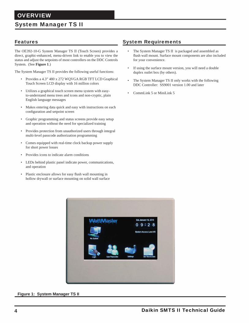
The OE392-10-G System Manager TS II (Touch Screen) provides a direct, graphic-enhanced, menu-driven link to enable you to view the status and adjust the setpoints of most controllers on the DDC Controls System. (See Figure 1.)
The System Manager TS II provides the following useful functions:
• Provides a 4.3” 480 x 272 WQVGA RGB TFT LCD Graphical Touch Screen LCD display with 16 million colors
• Utilizes a graphical touch screen menu system with easy-to-understand menu trees and icons and non-cryptic, plain English language messages
• Makes entering data quick and easy with instructions on each confi guration and setpoint screen
• Graphic programming and status screens provide easy setup and operation without the need for specialized training
• Provides protection from unauthorized users through integral multi-level passcode authorization programming
• Comes equipped with real-time clock backup power supply for short power losses
• Provides icons to indicate alarm conditions
• LEDs behind plastic panel indicate power, communications, and operation
• Plastic enclosure allows for easy fl ush wall mounting inhollow drywall or surface mounting on solid wall surface
System Manager TS II
System Requirements
• The System Manager TS II is packaged and assembled as fl ush wall mount. Surface mount components are also included for your convenience.
• If using the surface mount version, you will need a double duplex outlet box (by others).
• The System Manager TS II only works with the following DDC Controller: SS9001 version 1.00 and later
• CommLink 5 or MiniLink 5
Figure 1: System Manager TS II

Daikin SMTS II Technical Guide
COMPONENTS AND WIRING
5
Mounting, Wiring, Initializing, and Updating
Environmental Requirements
The System Manager TS II needs to be installed in an environment that can maintain a temperature range between 14°F and 158°F with less than 90% RH levels (non-condensing).
Mounting
The System Manager TS II is housed in a plastic enclosure designed for mounting in hollow drywall construction or a control panel cover with the fl ush wall mount version (shown in Figure 3, page 6) or on a concrete, brick, or other solid wall surface with the surface mount version (shown in Figure 4, page 7).
The fl ush wall mount version has integral wingnut paddles that are tight-ened after installation to grip the drywall and hold the System Manager TS II in place. For mounting in a control panel cover or other thin mate-rial, (4) adhesive backed rubber pads are provided to assist in securing the System Manager TS II into the cutout in the panel. These pads are applied to the wingnut paddles to provide a non-slip mounting against the panel’s sheet metal surface. See Figure 2 for pad placement details.
The surface mount version is designed to be installed in a double duplex outlet box (by others). Both mounting styles of the System Manager TS II feature an integral, magnetically-secured face plate which can be easily removed for reset of the display when required.
The System Manager TS II should be mounted at approximately eye level to allow for ease of programming and reading of the display. The System Manager TS II is typically mounted in the building manager’s or superintendent’s offi ce or in an equipment room, but is also quite suitable for mounting in any location or with most decors.
Care
The System Manager TS II should be cleaned with a soft, dust-free cloth. Do not use any liquid to clean your System Manager TS II. You should press the < Suspend> button located behind the cover to temporarily freeze the touch pad before you attempt to clean your screen. See the Troubleshooting section on page 19 for details.
Wiring
The System Manager TS II is connected to the local communications loop of the DDC system via 18 AWG 2-conductor, twisted pair with shield wire connected to the T, SHLD & R communication terminals on the back of the System Manager TS II. The communications wire used can be either our WattMaster # WR-LL-WG-18 communications wire or Belden #82760 wire or its equivalent.
The System Manager TS II also requires that 24 VAC (6 VA) power be supplied (by others) to its + and – wiring terminal located on the back of the System Manager TS II. See Figure 5, page 8 for wiring details. The wiring diagram depicts wiring the System Manager TS II to the DDC Controller. The System Manager TS II can also be wired to the local loop terminals on the MiniLink 5 or any other add-on controller’s local loop terminals. In these instances, it will still require a transformer to be wired.
Dipswitch and Jumper Settings
Because the DDC Controller runs at high speed, Dipswitch OPT1 should always be set to ON. As of April 2014, Dipswitch OPT4 should be set to ON by default. If you see your screen is not centered correctly, switch OPT4 to the opposite position. Dipswitches OPT2 and OPT3 should always be set to OFF. See Figure 5, page 8 for details.
If you have a Stand-Alone system (no CommLink or MiniLink, the TERM Jumpers must be ON. For applications with CommLink(s) and/or MiniLink(s), the TERM Jumpers must be OFF. See Figure 5, page 8 for details.
Technical Support
Call 1-855-324-5461 (855-Daikin-1) to talk to a Daikin Technical Sup-port Representative. Support is available Monday through Friday, 7:00 AM to 5:00 PM central standard time.
Front View (Cover Removed)Left Side View
US
E4
Place (2) On Each Paddle ArmAs Shown When Mounting In Sheet MetalPanel Or Other Thin Mounting Material. PadsAre Not Required For Drywall Mounting
Rubber PadsRubber Pads
Figure 2: System Manager TS II - Control Panel Mounting Pad Placement Detail ( Flush Wall Mount)

COMPONENTS AND WIRING
Daikin SMTS II Technical Guide6
Wall Mount Dimensions and Components
Figure 3: System Manager TS II Dimensions and Components ( Flush Wall Mount)
.1uF
YS102178 R4
WQVGA Graphical Interface
WattMaster Controls, Inc
C22
C24
R9
R7
R6
R5
R2
R1
C51
C39
C20
C19
C15
C14
C13
C12
C11
C10
C9
C7
C1
X3
8.00Mhz
OFF
1002
1002
1002
1002
10021002
1002
1002
1002
1002
1002
1002
1002
1002
1002
1002
1002
1002
1002
1002
1002
1002
1002
1002
1002
1002
1002
1002
1002
1002
1002
1002
1002
1002
1002
.1uF
.1uF
.1uF
.1uF
.1uF
.1uF
.1uF
.1uF
.1uF .1uF
.1uF
.1uF
.1uF
.1uF
.1uF
.1uF
.1uF
.1uF
.1uF
.1uF
.1uF
.1uF
.1uF
.1uF
.1uF
.1uF
.1uF
.1uF
.1uF
1002
.1uF
1002
1002
.1uF.1uF
.1uF
.1uF
LTC3824
1002
1002
1002
1002
1002
1002
66.000Mhz
MADE IN USA
330uF 50V 330uF
1002
SERIAL #
OP
T4
OP
T3
OP
T2
OP
T1
TERM
RTC
YS102178 R4
WQVGA Graphical Interface
WattMaster Controls, Inc
CAL
5V 3.3V 2.5V
J3
R34
R16
R13
R8
R39
X2
R26R17
R14
C22
C24
U13
R49
R48
R47
R46
R45
R44
R43R40
R37
R35
R32
R31
R29
R27
R24
R22
R12
R11
R10
R9
R7
R6
R5
R2
R1
L5
L4
D12
D11
D1
C51C50
C45
C41
C39
C36
C20
C19
C18
C17 C16
C15
C14
C13
C12
C11
C10
C9
C8
C7
C6
C5 C4
C1
J1
R41
C23
C25
C26
R42
X3
R20
C27
C34 C40
U10
U11
C28
C29 R18
C35
D2
L1
R25
C31
R19
U9
R28
C32
R30
R33
C30
R15Q2
R21
R23
SW1
C2
C3
V1
R36
1002
R S T +
1002
R
T
5V
GND
4.53
1.78
2.11
5.73
3.790.97
Wingnut
Front View (Cover Removed)Left Side View
Back View
Display
Circuit
Board
Communications &
Power Terminals
Wingnut
Screw
0.26
Wall Cutout Dimension
Wall Cutout Dimension
5.10
3.83
0.320.36
WARNING: LOW VOLTAGE CLASS 2 USE ONLY
US
E4
CO
RN
ER
HO
LE
ST
OM
AR
KW
ALL
OP
EN
ING
US
E4
CO
RN
ER
HO
LE
ST
OM
AR
KW
ALL
OP
EN
ING
LEDs
Button
4-PinHead

Daikin SMTS II Technical Guide
COMPONENTS AND WIRING
7
Surface Mount Components and Dimensions
5.73
3.790.97
Front View (Cover Removed)Left Side View
Back View
Display
C2
2
R9
R7
R6
R5
R2
C19
C1
5
C7
C1
1002
1002
1002
1002
10
02
10
02
10
02
10
02
.1uF
.1uF
.1uF
.1uF
.1uF
.1uF
.1uF
10
02
TERM
5V
J3
C2
2
R9
R7
R6
R5
R2
D1
C19
C18
C16
C1
5
C7
C1
J1
V1
R S T +
66.000Mhz
0.16 Dia. Mounting Hole
1.24
4.54
3.32
0.59
3.26 1.21
2.25
2.83
0.16 Dia. Mounting Slot
WARNING: LOW VOLTAGE CLASS 2 USE ONLY
US
E4
CO
RN
ER
HO
LE
ST
OM
AR
KW
ALL
OP
EN
ING
US
E4
CO
RN
ER
HO
LE
ST
OM
AR
KW
ALL
OP
EN
ING
LEDs
Buttons
4-PinHead
Figure 4: System Manager TS II Dimensions and Components ( Surface Mount)

Zone
ZoneCOMPONENTS AND WIRING
Daikin SMTS II Technical Guide8
SMTS II to DDC Controller Wiring
Figure 5: System Manager TS II to DDC Controller Wiring
.1uF
YS102178 R4
WQVGA Graphical Interface
WattMaster Controls, Inc
C24
R9
R7
R6
R5
R2
R1
C51
C39
C20
C19
C15
C14
C13
C12
C11
C10
C9
C7
C1
X3
8.00Mhz
OFF
1002
1002
1002
1002
10021002
1002
1002
1002
1002
1002
1002
1002
1002
1002
1002
1002
1002
1002
1002
1002
1002
1002
1002
1002
1002
1002
1002
1002
1002
1002
1002
1002
1002
1002
.1uF
.1uF
.1uF
.1uF
.1uF
.1uF
.1uF
.1uF
.1uF .1uF
.1uF
.1uF
.1uF
.1uF
.1uF
.1uF
.1uF
.1uF
.1uF
.1uF
.1uF
.1uF
.1uF
.1uF
.1uF
.1uF
.1uF
.1uF
1002
.1uF
1002
1002
.1uF.1uF
.1uF
.1uF
LTC3824
1002
1002
1002
1002
1002
1002
66.000Mhz
MADE IN USA
330uF 50V 330uF
1002
SERIAL #
OP
T4
OP
T3
OP
T2
OP
T1
TERM
RTC
YS102178 R4
WQVGA Graphical Interface
WattMaster Controls, Inc
CAL
5V 3.3V 2.5V
J3
R34
R16
R13
R8
R39
X2
R26R17
R14
C24
U13
R49
R48
R47
R46
R45
R44
R43R40
R37
R35
R32
R31
R29
R27
R24
R22
R12
R11
R10
R9
R7
R6
R5
R2
R1
L5
L4
D12
D11
D1
C51C50
C45
C41
C39
C36
C20
C19
C18
C17 C16
C15
C14
C13
C12
C11
C10
C9
C8
C7
C6
C5 C4
C1
J1
R41
C23
C25
C26
R42
X3
R20
C27
C34 C40
U10
U11
C28
C29 R18
C35
D2
L1
R25
C31
R19
U9
R28
C32
R30
R33
C30
R15Q2
R21
R23
SW1
C2
C3
V1
R36
1002
R
R
S
S
T
T
T-
SH
R+
+
+1002
R
T
5V
GND
System Manager TS II-GBack View
BLACK (R)
BLACK (R)
BLACK (R)
RED (24 VAC)
RED (24 VAC)
To (24 VAC)Transformer +
To
RTe
rmin
al
On
DD
C
To
STe
rmin
al
On
DD
C
To
TTe
rmin
al
On
DD
C
To (24 VAC)Transformer -
BROWN (GND)
Line Voltage
24 VAC Transformer5 VA Minimum
BROWN (GND)
WHITE (T)
WHITE (T)
WHITE (T)
BARE (S)
BARE (S)
BARE (S)
Run 2 ConductorTwisted Pair W/ShieldCable. WattMasterWR-LL-WG-18 CableOr Equivalent FromSystem Manager ToDDC Controller
Run 2 Conductor 20 Ga. Minimum Cable FromSystem Manager TS Terminals To 24 VAC
TERM
NOTE: For Stand-AloneInstallations (No CommLinkor MiniLink), Both TERMJumpers Must Be ON.For All Applications WithCommLink(s) Or MiniLink(s),Both Jumpers Must Be OFF.
DDC Controller - Front View
OFF
OP
T4
OP
T3
OP
T2
OP
T1
SW1 NOTE: Dip Switch OPT1Should Be Set To ON ForHigh Speed Applications.OPT2 & OPT3
. As Of April 2014,OPT4 Should Be Set To ONBy Default. If You See YourScreen Is Not CenteredCorrectly, Switch OPT4 ToThe Opposite Position.
Should BeSet To Off
RSLOO"R""T""SH
AN
BI5
BI7
BI1
BI2
BI3
BI4
BI8
BI6
AI1
AI2AI3
AI4
AI5
AI6
AI7
AI8
BINAR
O
24
POLA
BE
C
Wa#S
ENTER
UP
DOWN
ALARM
MENU
RELAY CONTACTRATING IS 1 AMP
MAX @ 24 VAC
RS-485 COMM
LOOP WIRE
“R” TO “R”,“T” TO “T”“SHLD” TO “SHLD”
24 VAC POWERONLY
WARNING!
POLARITY MUST
BE OBSERVED
OR THE
CONTROLLER
WILL BE
DAMAGED
ANALOG INPUTS
AI1:
A 2:I
A 3:I
A 6:I
A 7:I
A 8:I
BI1:
BI2:
BI3:
BI4:
BI5:
BI6:
BI7:
AO1
AO2
AO3
SPACE TEMP
CO2 SENSOR
OUTDOOR AIR TEMP
ECONOMIZER FEEDBACK
OUTDOOR AIR HUMIDITY
SPACE HUMIDITY
REMOTE START/STOP
FAN PROVING SWITCH
CLOGGED FILTER SWITCH
EMERGENCY SHUTDOWN
COMP PRESSURE SW 1
DEFROST SWITCH (ES)
LOAD SHEDDING
ECONOMIZER DAMPER:
MOD HGRH:
EXHAUST FAN (SSR):
A 4:I
A 5:I
BI8:
BINARY INPUTS (24V)
G OUTPUTSANALO
WattMaster Label#S 000067W
Rev.: 1G
E-BUSEXPANSION
E-BUSEXPANSION
+24 VAC
GND
HEAT STG2: RLY6
REV. VALVE(S): RLY8
www.wattmaster.com
COMP2/STG2: RLY2
OE377-26B-00001 PCBCG100
24V RLY2: COM2
BLOWER STG2: RLY4
COND FAN: RLY7
24V RLY: COM3-8
USB
AO4ALARM (SSR):
M
BINARY OUTPUTS
24V 3-8RLY: COM
HEAT STG1: RLY5
BLOWER STG1: RLY3
24V RLY1: COM1
COMP1/STG1: RLY1
SPACE SLIDE ADJUST
SUPPLY AIR TEMP
COMP PRESSURE SW 2

Daikin SMTS II Technical Guide
NAVIGATION
9
Main Screen Icons and Button Functions
Icons and Button Functions
System settings and screens are easily accessible by simply touching one of the fi ve icons on the Main Screen. The subscreens contain blue high-lighted data entry boxes with accessible number keypads for data entry and screen maneuvering buttons such as <Esc>, <Back>, and <OK>.
NOTE: Do not attempt to make changes to the Touch Screen while the Unit Controller is initializing. This can cause programming errors.
Main Screen IconsThere are fi ve Main Screen icons. See Table 1 for a list of the Main Screen icons and their functions.
Icon Main Screen Icons
The < My System> icon takes you to a Unit Selection Screen which takes you directly to the selected controller’s Status Screen.
The < Login> icon takes you to the Login Screen where you enter your passcode.
The < User Passcodes> icon takes you to the System Manager Passcode Levels Screen if you are a Level 3 user.
The < Settings> icon takes you to the System Settings Screen where you can change the Backlight settings, set the System Manager address, and enable alarm polling. System settings are only accessible to a Level 3 user.
The < Set Time & Date> icon takes you to the Set Time and Date Screen. Any level of user can set the time and date.
Navigation ButtonsSee Table 2 for a list of Navigation buttons and their functions.
Button Function
EscUse the < Esc> (Escape) key to exit from data entry without saving any new data.
Back
Back
Use the small < Back> button located in the top right corner of a Data Entry Screen to return to the controller’s Status Screen. Use the large < Back> button located at the bottom left of other screens to return to the previous screen.
UpUse the < Up> key to step to the next screen or greater value.
DnUse the < Dn> key to step to the previous screen or a lesser value.
Selection, Confi guration, and Setpoint ButtonsSee Table 3 for a list of Selection, Confi guration, and Setpoint buttons and their functions.
Button Function
OKUse the < OK> key to save the data you just se-lected or entered.
Touch the grey radio button to make your selection. A white circle will designate that the item isselected. You can only select one radio button item per screen.
Touch the grey square selection box to make your selection. A white square will designate that the item is selected. You can make numerous square box item selections per screen.
Setpoints
The < Setpoints> button, appearing on the control-ler’s Status Screen, takes you directly to the control-ler’s Temperature Setpoint Screen.
Overrides
The <Overrides> button, appearing on various controllers’ Status Screens, takes you directly to the controller’s Force Schedules Screen.
Schedules
The < Schedules> button, appearing on various controllers’ Status Screens, takes you directly to the controller’s Schedule Screen.
Holidays
The < Holidays> button, appearing on various controllers’ Status Screens, takes you directly to the controller’s Holidays Screen.
The < Alarm> button, appearing on the controller’s Status Screen, takes you directly to the controller’s Alarms Screen. If red, alarm(s) are present. If black, no alarm(s) are present.
Table 2: Navigation Button Functions
Table 1: Main Screen Icon Functions
Table 3: Confi guration Selection Buttons

Zone
ZoneNAVIGATION
Daikin SMTS II Technical Guide10
Main Screen Icons and Button Functions
DDC Controller Setpoint ButtonsThe DDC Controller Setpoint Buttons are located at the bottom of each Controller Setpoints Screen. See Table 4 for a list of the Setpoint buttons and their functions. Level 1 and Level 2 users can view these screens and change occupied heating and cooling setpoints, but only a Level 3 user can make changes to all setpoints.
Button Function
Temps
The < Temps> button, located at the bottom of the controller’s Setpoints Screen, takes you directly to the controller’s Temperature Setpoints Screens.
The < Delays> button, located at the bottom of the controller’s Setpoints Screen, takes you directly to the controller’s Staging Delays Screens.
The < Econo> button, located at the bottom of the controller’s Setpoints Screen, takes you directly to the controller’s Economizer Setpoints Screens.
Misc
The < Misc> button, located at the controller’s Setpoints Screen, takes you directly to the controller’s Miscellaneous Set-points Screens.
Cal
The <Cal> button, located at the bottom of the controller’s Setpoints Screen, takes you directly to the controller’s Calibration Screens.
Config
The < Confi g> button, located at the controller’s Setpoints Screen, takes you directly to the controller’s Confi guration Screens.
Table 4: DDC Setpoint Icons
Delays
Econo

Daikin SMTS II Technical Guide
MAIN SCREEN FUNCTIONS
11
Entering Your System Manager Passcode
NOTE: There are three available passcode levels. Level 1 defaults to 1111, Level 2 defaults to 2222, and Level 3 defaults to 3333. These defaults can be changed by anyone who logs in at Level 3.
When you power-up your System Manager TS II, the message System Secured is displayed on the upper right corner of the Main Screen.
Touch the < Login> icon found on bottom left of the Main Screen and type the default Level 3 passcode of “3333” using the number keypad to gain access to all setpoint and confi guration items. See Figure 7.
First Things First
The fi rst thing you need to do when setting up your Touch Screen is to Login. The second thing you need to do is establish user passcodes. The third thing you need to do is set the clock. After you complete these simple tasks, you are ready to set your system’s settings, view controller status screens, and change schedules and setpoints.
NOTE: Do not attempt to make changes to the Touch Screen while the Unit Controller is initializing. This can cause programming errors.
Main Screen
Once you have connected your System Manager TS II to the controller and have powered it up with the proper power supply, the Main Screen will appear. See Figure 6.
Figure 7: Login Screen
Enter the 4 digit Passcode
for the required Level.
Level #1:
Can change space setpoints.
Level #2:
Can change schedules.
Level #3:
Can change all setpoints.
Esc 1 2 3
4
7
- 0 .
98
5 6
OK
<<
Currently: ****DATA ENTRY
Logging In
Figure 6: Main Screen
NOTE: For security reasons, the current passcode characters displayed at the top of the screen are never shown and appear as asterisks.
Touch <OK>. Touch <Esc> if you accessed this screen by mistake and do not wish to change the current access level.
The Login Screen will automatically close, and the passcode will be tested against all previously defi ned passcodes to determine the pass-code’s access level.
If 3333 is still the active Level 3 code, the status message System Access Level 3 will now be displayed on the upper right corner of the Main Screen.
NOTE: System Access will automatically default to System Secured after time set for Backlight Timeout in the System Manager Settings Screen (see Figure 12, page 14). If timeout is set to zero, the passcode will timeout after two minutes.

Zone
ZoneMAIN SCREEN FUNCTIONS
Daikin SMTS II Technical Guide12
Editing Passcodes
Passcode Clearance LevelsBelow is a list of the passcode levels, default codes, and actions that can be performed at the various levels.
Level 0—No Passcode Needed, SystemSecuredLevel 0 users can view temperatures and status points. They can also change the system date and time, but no changes to any controller setpoints can be made.
Level 1—Default: 1111Level 1 users can view temperatures and change space temperature setpoints. No changes to schedules or other settings can be made.
Level 2—Default: 2222Level 2 users can change space temperature setpoints and operating schedules but not confi guration settings.
Level 3—Default: 3333Level 3 users have system manager access and can change all setpoints and confi gurations, including default passcodes. This Level is normally reserved for qualifi ed HVAC service personnel.
Edit Passcodes
WARNING: MAKE SURE YOU CHANGE ALL PASS-CODES AS SOON AS POSSIBLE TO SECURE THE SYSTEM!
NOTE: Only a Level 3 user (system manager level) can change Level 1, 2, and 3 passcodes.
NOTE: Do not use the same passcode for all 3 levels. If you do, each passcode will default to Level 1.
From the Main Screen, touch the < User Passcodes> icon. The System Manager Passcode Levels Screen will appear. See Figure 8.
To change a passcode, touch the blue highlighted box containing the current passcode. The keypad will appear with instructions for changing the passcode. See Figure 9.
The current passcode will appear on the top menu bar. Type in the new four-digit passcode. You cannot use the period or minus characters in your passcode. Use the <<<> key if you make a mistake. Touch <Esc> to return to the previous screen without changing the passcode. When you have typed in the new passcode, touch <OK>. The System Manager Passcode Levels Screen should display the passcode you entered.
NOTE: If you change the Level 3 passcode, make sure to write it down. If you should happen to forget the Level 3 passcode, contact Daikin Technical Support.
Touch <Back> to return to the Main Screen.
Figure 8: System Manager Passcode Levels Screen
1111
Passcode Levels
You can limit access to critical settings
by giving the user access only to those
items needed to maintain comfort levels
or to modify operating hours.
All critical setpoints and configurations
are protected by Level #3 and should not be
accessed except by a service technician.
Level #1 Passcode
{ Can change Space Setpoints }
2222
Level #2 Passcode
{ Can change Schedules & Holidays }
3333
Level #3 Passcode
{ Can change All Setpoints }Back
Esc 1 2 3
4
7
- 0 .
98
5 6
OK
<<
Currently: 1111DATA ENTRY
Enter the 4 digit Passcode
for Level 1.
Level #1:
Can change space setpoints.
Level #2:
Can change schedules.
Level #3:
Can change all setpoints.
Figure 9: Change Passcode Screen

Daikin SMTS II Technical Guide
MAIN SCREEN FUNCTIONS
13
Setting the System Clock
Set Time and Date
When you fi rst power up your System Manager TS II, you will need to change the day of the week, the time, and the month, day, and year to the current time and date. If your system has been turned off or has been down for a long time, you may have to do the same, although the time and date can maintain itself for several days. Any level of user can change the time and date settings.
The day of the week, the time, and the date appear at the top right on the Main Screen. See Figure 6, page 11.
From the Main Screen, touch the < Set Time & Date> icon. The Set Time & Date Screen will appear. See Figure 10.
In the example above, the current time and date is 2:12 PM, January 16, 2016. There is no day of the week selected yet.
Set Day of the Week: Select the day of the week by simply touching your selection. The day of the week text will change from white to blue.
Set Hour, Minute, Month, Day, and Year: Touch the blue high-lighted box to have each selection screen appear. See Figures 10 & 11. Read the instructions on each screen for entering data.
Broadcast: When you are fi nished setting the clock, touch the <Broadcast> button to broadcast the Time and Date to all Units. The following message will appear:
Figure 10: Set Time & Date Screen
Back
Set Time & Date
Broadcast
System Manager Settings
Mon Tue Wed
Hour Minute Month Day Year
14 12 1 16 16
Sun ThuSunThu FriSunFri SatSunSat
Esc 1 2 3
4
7
- 0 .
98
5 6
OK
<<
Currently: 10DATA ENTRY
Set Clock Hour
Enter the Current Hour in
24 hour military format.
Example:
5:00 AM = 5
5:00 PM = 17
Hi Limit: 23
Lo Limit: 0
Figure 11: Set Clock Hour
Set Clock Hour: Touch the number buttons to enter the current hour in 24 hour military format. Valid entries are from 0-23. Press <OK>.
NOTE: See Appendix for Military Time Conversion table.
Set Clock Minute: Touch the number buttons to enter the current minutes. Valid entries are from 0-59. Press <OK>.
Time & Date Broadcast to All Units.
OK
Set Clock Month: Touch the number buttons to enter the current month. Valid entries are from 1-12. Press <OK>.
Set Clock Day: Touch the number buttons to enter the current day of the month. Valid entries are from 1-31. Touch <OK>.
Set Clock Year: Touch the number buttons to enter the current year. Valid entries are from 0-99. Touch <OK>. Note: The year is based on the current century; therefore, 16 = 2016. If you enter more than two digits, e.g. 2016, the system will not recognize your entry.

Zone
ZoneMAIN SCREEN FUNCTIONS
Daikin SMTS II Technical Guide14
System Manager Settings
Figure 12: System Manager Settings Screen
30
System Manager Settings
Backlight Timeout
Backlight Intensity
System Manager Address
Back
30 Minutes
3050 %
3063
One to One Unit Connection
System Manager Version: 1.00
System Manager Settings
Additional system settings are available under the <Settings> icon. These include setting the Backlight Timeout, the Backlight Intensity Per-centage, the System Manager Address, and One to One Unit Connection.
From the Main Screen, touch the < Settings> icon. The System Manager Settings Screen will appear. See Figure 12.
One to One Unit Connection: If your System Manager TS II is directly connected to only one unit, you may wish to select this option to bypass the Unit Selection Screen and go directly to the unit’s Status Screen. The controller must be set to address #1 for this to work. Touch the black box to the left of this item on the screen to select it. The box will turn white. If you wish to deselect this option, simply touch the box again.
Backlight Timeout: This setting is actually a setting for three separate functions—Backlight Timeout, Main Screen Timeout, and Passcode Timeout. To set the Backlight Timeout, enter the amount of time you wish the screen to maintain the active intensity level after the last touch pad activity occurs. The High limit is 30 and the Low limit is 0. 0 = No Timeout. The System Manager TS II will return to the Main Screen display at the same rate as the Backlight Timeout, except that if set to 0, the Main Screen will display after 2 minutes. The Passcode will timeout at the same rate as the Backlight Timeout, except that if set to 0, the Passcode will timeout after 2 minutes and will return to System Secured Setting.
Backlight Intensity Percentage: Enter the percentage of light level you wish to maintain whenever touch pad activity occurs. The High limit is 100 and the Low limit is 0.
System Manager Address: Enter the address of the System Manager TS II according to the rules below:
• If the on-board CommLink jumpers are installed on the DDC Controller or an external CommLink 5 or MiniLink 5 is installed, then the System Manager Address needs to be set to 63.
• If the on-board CommLink jumpers are not installed and there is no CommLink 5 or MiniLink 5, then the System Manager address needs to be set to 0.
• Multiple Managers—If you have more than one System Manager, it must be addressed with a unique address between 1 and 63.
NOTE: To use Multiple Manager addressing, you must have a CommLink 5 or MiniLink 5 installed.
System Manager Version: The version number of the System Manager software appears on the bottom menu bar. This version number is important to know for troubleshooting purposes.

Daikin SMTS II Technical Guide
DDC CONTROLLERS
15
Selecting Units and Viewing DDC Status Screen
My System Unit Selection
From the Main Screen, touch the < My System> icon. The Selected Unit Screen will appear. See Figure 13.
NOTE: If you have chosen the One to One Unit Connection in the System Manager Settings Screen, this screen will not appear. Instead, the unit’s Status Screen will appear.
Back
Selected Unit [Loop 1 - Unit 1]
1
GO
0 10Dn DnDnDn
Up Up Up Up
Figure 13: Unit Selection Screen
In Figure 13, Loop 1 and Unit 1 are selected as indicated in the fi gure with white text. They also appear in the Top Menu Bar in brackets.
Use the <Up> and <Dn> buttons to move up and down through the loops and units. Enter the desired Loop # and Unit # and then touch <GO> to access the unit’s Status Screen.
Viewing DDC Controller Status Screens
Figure 14 depicts the fi rst Controller Status Screen. Notice that the controller is identifi ed by loop number and unit number - in this case, 0110 represents Loop 1, Unit 10.
Figure 14: DDC Controller Status Screen 1
While in the Status Screen, touch the <Up> and <Dn> buttons to view more status screens displaying relays and operating setpoints. The set-points and relays appear in the middle of each screen. The screens roll back to the fi rst Status Screen. There are 8 Status Screens.

Zone
ZoneDDC CONTROLLERS
Daikin SMTS II Technical Guide16
Figure 16: DDC Controller Alarm Status Screen 1
Viewing DDC Controller Alarm Status
To view alarm status, touch the <ALARM> button on the unit’s Status Screen. See Figure 15. The Alarm Status Screens will display. See Figures 16 & 17.
If there are no alarms present, this red <ALARM> button will display <No Alarms> and will be gray.
NOTE: The < ALARM> button only appears on the screen if the unit has an active alarm condition. Only a Level 3 user has the option to enable or disable each type of alarm.
Viewing DDC Controller Alarms
Figure 15: DDC Controller Status Screen 1
Touch the <Next> button to go to the next Alarm Status Screen.
Figure 17: DDC Controller Alarm Status Screen 2
No Alarms

Daikin SMTS II Technical Guide
DDC CONTROLLERS
17
Viewing and Setting Schedules & Holidays
Viewing and Setting Schedules
To view and set schedules for the DDC controller, touch the <Schedules> button found at the bottom of any Status Screen (Figure 15, page 16). The Schedules Screen will appear. See Figure 18. The default day will be Sunday and the default event start/stop times will be midnight.
A Level 2 user can set two schedules per day for individual days of the week, all weekdays, weekends, and holidays. All times are entered in military time format.
If you wish to enter a schedule for a certain day of the week, fi rst touch the day of the week at the top of the screen. Otherwise, the day defaults to Sunday. Touch the start and stop time for each Event and enter the desired times. See Figure 19. All times must be entered in military time format. See the Military Time Table in the Appendix, page 24.
Figure 18: DDC Controller Schedules
Figure 19: Schedule Times Screen
Once back at the Schedules Screen, you can continue setting schedules day by day or use following options:
SEND TO <All Days> - Touch this button to send the schedule appearing on the screen to all days of the week, except for holidays.
SEND TO <Weekdays> - Touch this button to send the schedule to weekdays only. You will need to set up a separate schedule for Saturday and Sunday when selecting this option.
CLEAR <All Schedules> - Touch this button to clear all schedules.
SET <24 Hr Mode> - Touch this button to have the system run con-tinuously, 24 hours a day, 7 days a week including holidays. All event times will display 11:59 PM.
Figure 20: Holidays Schedule Screen
Viewing and Setting Holidays
To view and set holidays for the DDC Controller, touch the < Holidays> button found at the bottom of the Status Screen (Figure 15, page 16). The Holidays Schedule Screen will appear. See Figure 20. The holidays in the screen will initially not be set. You can only set holidays for the current year. You must be a Level 2 user in order to set holidays.
Simply touch the day(s) of the month to select holidays. Touch the <<> button to go back one month and the <>> button to go forward one month.
There are 14 holiday periods available for each year. These holiday pe-riods can be a single day or they can span days, weeks, or even months.
For example, if you want to schedule a summer break, you need only schedule one holiday period to defi ne a two or three month break from operating in the occupied mode.
Every defi ned holiday uses the Holiday operating schedule programmed in the controller’s Schedules Screen.
Holidays can only be programmed for the current year. You cannot program holidays before the next year occurs. Holidays do not automatically adjust for the new year, so you will need to access this screen after the new year and make necessary adjustments to the days that fl oat, such as Memorial Day.
Touch <OK> to save the time you entered or touch <Esc> to exit the Schedule Times Screen without changing the time and return to the Schedules Screen (Figure 18).
To eliminate a schedule from any event, simply enter a zero for the Start and Stop time for that day. The screen will display 12:00 am for both the Start and Stop times, indicating that the equipment will not activate on that day.

Zone
Zone
VCM-X CoVCM-X Co
DDC CONTROLLERS
Daikin SMTS II Technical Guide18
Schedule Override
To Force Schedules, from the DDC Controller Main Status Screen, touch the <Overrides> button located at the bottom of the screen. The following options will appear:
Schedule Auto ModeTouch the radio button to select the schedule option. Default is Schedule AUTO Mode. This selection will remain in effect unless it is changed again on this screen. Schedule overrides do not automatically time out after a certain period of time.
Schedule AUTO Mode—Select this to restore normal schedule operations. Schedule FORCED ON—Select this to Force the unit into continuous Occupied Mode operation. Schedule FORCED OFF—Select this to Force the unit into continuous Unoccupied Mode operation.
Forcing Schedules & Accessing & Entering Setpoints
Figure 21: DDC Controller Status Screen
Figure 22: DDC Controller Temperature Setpoints
Accessing and Entering DDC Controller Setpoints
While in the DDC Status Screen (see Figure 21), touch the < Setpoints> button found on the bottom menu bar. The DDC Controller’s Temperature Setpoints Screen will appear. See Figure 22. Level 1 and Level 2 users can change occupied space temperature setpoints, but only Level 3 users can change all setpoints.
Individual setpoint and confi guration buttons are located at the bottom of the Setpoint Screens. See Figure 23. Simply touch a specifi c button to access that category.
Within each Setpoint Screen, touch the < Back> button until you return to the Status Screen.
Use the <+> and <-> buttons to scroll through the setpoints and confi gu-rations. Simply touch the blue highlighted box to change the setpoint. Each setpoint data entry screen will provide a defi nition of the setpoint and specifi c instructions for entering the setpoint and will include the setpoint range as in the example below, Figure 24.
Touch <OK> to have the system accept the new value. If you enter a setpoint that is not in the valid range, the setpoint will remain as is and will not change.
Each setpoint data entry screen is self-explanatory due to the detailed description and high and low limits. Therefore, each setpoint will not be described in this manual.
Figure 23: DDC Controller Setpoint Buttons
Figure 24: DDC Cooling Setpoint Data Entry Screen

ntrollersntrollers
Daikin SMTS II Technical Guide
APPENDIX
19
Troubleshooting
System Manager TS II LEDs, Buttons, Dipswitches & Jumpers
LEDs and system function buttons are located behind your System Manager TS II’s cover. See Figure 25 for locations. Dipswitches and jumpers are located on the back of your System Manager TS II.
Power LEDThis LED will light up and stay on as long as power is supplied to your TS.
Operation LEDThis LED will blink once a second to indicate that the system is alive.
Update LEDThis LED will turn on when the Update program is running.
Screen Refresh LEDThis LED will turn on when the screen refreshes.
Communications LEDThis LED will light up and blink when there is a connection with the CommLink and/or network. If you are using your TS in stand-alone mode, this LED will not light up.
Reset ButtonPress this button to reset the screen. The screen should refresh itself to the Main Screen within 2 minutes.
Diagnostics ButtonUnder the direction of Daikin Technical Support, you may have to perform diagnostics on your System Manager TS II. Press this button to do so.
Touch Screen Suspend ButtonPress this button to temporarily freeze the touch screen function of your System Manager TS II in order to clean the screen. Always use a dry, dust -free cloth to clean the screen.
OPT1 DipswitchThe OPT1 Dipswitch should be always be set to ON. This Dipswitch is located on the back of the System Manager TS. See Figure 5, page 8 for location.
OPT4 DipswitchAs of April 2014, Dipswitch OPT4 should be set to ON by default. If you see your screen is not centered correctly, switch OPT4 to the opposite position. This Dipswitch is located on the back of the System Manager TS. See Figure 5, page 8 for location.
TERM JumpersBoth TERM Jumpers must be ON for Stand-Alone applications (No CommLink or MiniLink). Both TERM Jumpers must be OFF for applications with CommLink(s) and/or MiniLink(s). See Figure 5, page 8 for location.
Reset Button
A302-12
Power LED Communications LED
Diagnostics Button
Suspend Button
Not Used
Not UsedScreen Refresh LED
Operation LEDUpdate LED
Figure 25: System Manager TS II LEDs & Buttons

Zone
Zone
VCM-X CoVCM-X Co
APPENDIX
Daikin SMTS II Technical Guide20
System Confi guration
System Confi guration Options
A DDC Controller can be used as a Stand-Alone System (one DDC Controller only), connected together on an Interconnected System (multiple DDC Controllers only) or connected together on a Network System (multiple DDC Controllers and/or Add-On Controllers) to form a complete Controls System that can be programmed and monitored with one or both of the available Operator Interfaces.
For detailed information about the DDC Controls System, please see the DDC Controller Technical Guide.
Operator InterfacesThe Operator Interfaces are designed to provide for programming and monitoring of DDC Controller(s) and/or any Add-on Controller(s) con-nected to your System. You can use one or both of these interfaces on the same System. See Figure 26. The Operator Interfaces available for use with the DDC Control System are as follows:
• System Manager TS II
• Computer with PrismD Computer Front End Software Installed and on-board CommLink or external CommLink
Stand-Alone SystemThe Stand-Alone System is used when you have a single controller only. Programming and status monitoring are accomplished by selecting and installing one or both of the Operator Interfaces. See Figure 27, page 21 for a Typical Stand-Alone System Layout diagram.
Interconnected SystemThe Interconnected System is used when you have multiple controllers of the same type on your job. With this system, you simply connect the controllers together using WattMaster communications wire or 18-gauge, 2-conductor twisted pair with shield wire (Belden #82760 or equivalent). This allows for all controllers that are connected on the communications loop to be programmed and monitored from one or both of the available Operator Interfaces connected on the communications loop. See Figure 28, page 22 for a Typical Interconnected System Layout diagram.
Networked SystemIf you have 1 to 59 DDC Controllers that require information sharing, simply connect the controllers together using WattMaster communica-tions wire or 18-gauge, 2-conductor twisted pair with shield wire (Belden #82760 or equivalent). The Networked Single Loop System requires that either a MiniLink communication interface and/or CommLink com-munication interface are purchased and wired into the communications loop in a similar manner to the DDC Controllers.
The Networked Multiple Loop system is used when you have more than 59 DDC Controllers. These groups of controllers are broken up into multiple “Local Loops” that connect to each other via the “Network Loop.” Each individual MiniLink handles its specifi c local loop’s com-munications requirements. The CommLink communications interface handles all the communications between the individual MiniLinks to form the network loop. Up to 60 local loops can be connected together with this confi guration. This provides the capability for over 3500 con-trollers to be networked together. See Figure 29, page 23 for a Typical Networked System Layout diagram.
Figure 26: Available Operator Interfaces
System Manager TS II-GComputer, PrismD Software
& On-Board CommLink or CommLink 5
OperatorInterfaces

ntrollersntrollers
Daikin SMTS II Technical Guide
APPENDIX
21
Figure 27: Typical Stand-Alone System Layout
Stand-Alone System Layout
OperatorInterfaces
System ManagerTouch Screen II-G Personal Computer,
PrismD Software& On-Board CommLink

Zone
Zone
VCM-X CoVCM-X Co
APPENDIX
Daikin SMTS II Technical Guide22
Figu
re 2
8: T
ypic
al In
terc
onne
cted
Sys
tem
Lay
out
Interconnected System Layout
Co
mp
ute
r &
Co
mm
Lin
k 5
an
d P
ris
mD
So
ftw
are
(Se
t C
om
mL
ink
5 t
o S
ing
le)
Sy
ste
m M
an
ag
er
To
uc
h S
cre
en
II-
G

ntrollersntrollers
Daikin SMTS II Technical Guide
APPENDIX
23
Figu
re 2
9: T
ypic
al N
etw
orke
d Sy
stem
Lay
out
Networked System Layout
Op
era
tor
Inte
rfa
ce
Op
era
tor
Inte
rfa
ce
(Set
Co
mm
Lin
k 5
to M
ult
i)

Zone
Zone
VCM-X CoVCM-X Co
APPENDIX
Daikin SMTS II Technical Guide24
Military Time Conversion
The main difference between regular and military time is how hours are expressed. Regular time uses numbers 1 to 12 and a.m. and p.m. to identify each of the 24 hours in a day. In military time, the hours are numbered from 0000 to 2300.
Military time is based on a 24-hour day. Hours are numbered 0000 through 2300 and are recorded fi rst. The last two digits indicate the minute after the hour. Military time does not exceed 2359 hours. For example, midnight is recorded as 0000; one minute past midnight is 0001; 1 a.m. is 0100, 1 p.m. is 1300, and so on.
Regular and military time express minutes and seconds in exactly the same way. When converting from regular to military time and vice versa, the minutes and seconds do not change.
Regular time requires the use of a.m. and p.m. to clearly identify the time of day. Since military time uses a unique two-digit number to identify each of the 24 hours in a day, a.m. and p.m. are unnecessary.
The following table summarizes the relationship between regular and military time.
RegularTime
MilitaryTime
12:00 a.m. 0000
12:30 a.m. 0030
1:00 a.m. 0100
1:30 a.m. 0130
2:00 a.m. 0200
2:30 a.m. 0230
3:00 a.m. 0300
3:30 a.m. 0330
4:00 a.m. 0400
4:30 a.m. 0430
5:00 a.m. 0500
5:30 a.m. 0530
6:00 a.m. 0600
6:30 a.m. 0630
7:00 a.m. 0700
7:30 a.m. 0730
8:00 a.m. 0800
8:30 a.m. 0830
9:00 a.m. 0900
9:30 a.m. 0930
10:00 a.m. 1000
10:30 a.m. 1030
11:00 a.m. 1100
RegularTime
MilitaryTime
11:30 a.m. 1130
12:00 p.m. 1200
12:30 p.m. 1230
1:00 p.m. 1300
1:30 p.m. 1330
2:00 p.m. 1400
2:30 p.m. 1430
3:00 p.m. 1500
3:30 p.m. 1530
4:00 p.m. 1600
4:30 p.m. 1630
5:00 p.m. 1700
5:30 p.m. 1730
6:00 p.m. 1800
6:30 p.m. 1830
7:00 p.m. 1900
7:30 p.m. 1930
8:00 p.m. 2000
8:30 p.m. 2030
9:00 p.m. 2100
9:30 p.m. 2130
10:00 p.m. 2200
10:30 p.m. 2230
11:00 p.m. 2300
11:30 p.m. 2330
Table 5: Military Time Conversion
Military Time Conversion
Table 5, cont.: Military Time Conversion

Daikin SMTS II Technical Guide
NOTES
25
ntrollersntrollers

Zone
ZoneNOTES
Daikin SMTS II Technical Guide26

Daikin SMTS II Technical Guide
NOTES
27

WattMaster Form: DK-SMTSII-TGD-01A Printed in the USA June 2016All rights reserved. Copyright 2016WattMaster Controls Inc. 8500 NW River Park Drive Parkville, MO 64152