Embed Size (px)
Citation preview

System identification of smart structures using a wavelet neuro-fuzzy model
This article has been downloaded from IOPscience. Please scroll down to see the full text article.
2012 Smart Mater. Struct. 21 115009
(http://iopscience.iop.org/0964-1726/21/11/115009)
Download details:
IP Address: 130.15.241.167
The article was downloaded on 29/08/2013 at 22:37
Please note that terms and conditions apply.
View the table of contents for this issue, or go to the journal homepage for more
Home Search Collections Journals About Contact us My IOPscience
IOP PUBLISHING SMART MATERIALS AND STRUCTURES
Smart Mater. Struct. 21 (2012) 115009 (12pp) doi:10.1088/0964-1726/21/11/115009
System identification of smart structuresusing a wavelet neuro-fuzzy model
Ryan Mitchell, Yeesock Kim and Tahar El-Korchi
Department of Civil and Environmental Engineering, Worcester Polytechnic Institute (WPI), Worcester,MA 01609-2280, USA
E-mail: [email protected], [email protected] and [email protected]
Received 9 January 2012, in final form 3 July 2012Published 21 September 2012Online at stacks.iop.org/SMS/21/115009
AbstractThis paper proposes a complex model of smart structures equipped with magnetorheological(MR) dampers. Nonlinear behavior of the structure–MR damper systems is represented by theuse of a wavelet-based adaptive neuro-fuzzy inference system (WANFIS). The WANFIS isdeveloped through the integration of wavelet transforms, artificial neural networks, and fuzzylogic theory. To evaluate the effectiveness of the WANFIS model, a three-story buildingemploying an MR damper under a variety of natural hazards is investigated. An artificialearthquake is used for training the input–output mapping of the WANFIS model. The artificialearthquake is generated such that the characteristics of a variety of real recorded earthquakesare included. It is demonstrated that this new WANFIS approach is effective in modelingnonlinear behavior of the structure–MR damper system subjected to a variety of disturbanceswhile resulting in shorter training times in comparison with an adaptive neuro-fuzzy inferencesystem (ANFIS) model. Comparison with high fidelity data proves the viability of theproposed approach in a structural health monitoring setting, and it is validated using knownearthquake signals such as El-Centro, Kobe, Northridge, and Hachinohe.
(Some figures may appear in colour only in the online journal)
1. Introduction
In recent years, smart control strategies have attracted a greatdeal of attention from the structural engineering community.However, a difficult problem in dealing with smart structuresand structural health monitoring is creating an effective modelof a nonlinear dynamic structure. Nonlinear systems occurwhen actuators and dampers, such as magnetorheological(MR) dampers, are implemented into a structure to aid inthe building’s ability to withstand destructive environmentalforces such as strong winds and earthquake loads. Being ableto mathematically model the structure and its correspondingnonlinear dampers is a challenging task in smart control. Itis generally known that the smart control system produces anonlinear behavior due to the nonlinear damping devices thata structure is equipped with, even though the structure itselfis typically assumed to behave linearly, as noted by Kim et al(2009). Therefore, the challenge is to create a mathematicalmodel to develop a relationship between the input and outputof a structure that uses a nonlinear damping device. This
paper proposes a new nonlinear system identification (SI)for describing nonlinear behavior of a seismically excitedbuilding equipped with smart dampers.
SI is essential in smart structures to create a mathematicalmodel from actual dynamic data. The goal of effective SI isto reliably predict how a system will behave under a varietyof dynamic loading scenarios such as far- and near-fieldearthquakes, as well as showing interactions between thesystem inputs and outputs. SI can be separated intotwo categories: parametric and nonparametric approaches,according to Adeli and Kim (2004). The parametric methodidentifies the structural properties of the system, includingstiffness and damping systems that are intrinsically imbeddedin the structure and its materials (Jalili-Kharaajoo 2004).The nonparametric method of SI is used to train data tothe input–output map of the system (Filev 1991). Thisnonparametric approach is useful to SI to bridge the gapbetween the linear and nonlinear parts of the system. Thishas successfully been done with neural networks as well as
10964-1726/12/115009+12$33.00 c© 2012 IOP Publishing Ltd Printed in the UK & the USA

Smart Mater. Struct. 21 (2012) 115009 R Mitchell et al
fuzzy logic systems. Furthermore, the incorporation of the twosystems provides a better learning model to use for SI.
The first system that is commonly used as a nonparamet-ric method, a fuzzy inference system, uses fuzzy set theory tocreate a set of rules that the system must follow. It is effectivein showing the complexities that arise from nonlinearities anddynamic system uncertainties, described by Gu and Oyadiji(2008). Since the early work done by Zadeh (1965), fuzzylogic has been applied to many SI issues (Takagi and Sugeno1985, Yan and Langari 1998, Kim et al 2011). A numberof studies on Takagi–Sugeno (TS) fuzzy models have beenconducted in recent years, and the results provide an effectiverepresentation of nonlinear systems with the aid of fuzzysets, fuzzy rules, and a set of local linear models (Adeli andSamant 2000, Alhanafy 2007, Filev 1991, Gopalakrishnanand Khaitan 2010, Johansen and Babuska 2003). Fuzzylogic theory in the field of large scale infrastructures hasbeen mainly used for nonlinear fuzzy control system design,described by Guo et al (2009). However, determination ofthe inherent parameters of a fuzzy inference system includesmany trials and errors. Therefore, incorporating neuralnetworks allows for automated adjustments of parametersthroughout computation.
Neural networks were created to imitate the cognitivemechanism of the human brain. The network is made up oflinked nodes, where each node computes an output from itsown input. The output of one node is then used as the inputfor the next node, and a link is created between each node.Neural networks are able to learn throughout the computationby adjusting the parameters to improve performance at eachnode. This is a useful characteristic of neural networksbecause it is able to recognize patterns and adjust theseparameters in order to better the end result and create a moreaccurate model. The neural network is useful to determinesome of these incomplete measurements to create a full modelof the structure, which can be seen through Hung et al (2003).However, it is challenging to design and analyze the neuralnetworks in a transparent way because it is a black boxmodeling framework.
An integration of these nonparametric SI models canbe made to create a new model, an adaptive neuro-fuzzyinference system (ANFIS). Its application to SI has beenresearched by (Gu and Oyadiji 2008, Jang et al 1997), but theapplication of an ANFIS model to the SI of civil engineeringstructures is still a relatively new research topic, with workbeing done by (Alhanafy 2007, Faravelli and Yao 1996,Gopalakrishnan and Khaitan 2010, Jalili-Kharaajoo 2004,Wang and Shi 2010). The only structural limitation of thissystem is that the network configuration must be feedforwardto avoid using more complex models. The ANFIS system isable to use a nonlinear system from fuzzy inference systemsas well as the adaptive knowledge from neural networksto create a more accurate model. The advantages of theANFIS system are its ability to create a nonlinear mapping,its use of adjustable parameters, including the membershipfunction (MF) type, the number of MFs, step size, andnumber of epochs. However, the ANFIS system includes longcomputation times that can become disadvantageous when
dealing in real time. This issue can be addressed by integratingwavelet transform algorithms with the ANFIS.
The incorporation of wavelet transforms into the ANFISmodel creates a wavelet-based ANFIS model, or a WANFISmodel. The inclusion of the wavelet transform as a meansof filtering data greatly reduces computation times for themodel, creating a model that outputs comparable results whilecomputing in a fraction of the time. Commonly, Fouriertransforms can be used to look at frequency domain responsesin dynamics, commonly used for SI, damage detection, andcontrol systems. A major disadvantage that occurs throughthe use of Fourier transforms for time–frequency resolutionsare the fixed windows, meaning Fourier transforms areallowed to be used for the full scale time window, postulatedby Thuillard (2001). However, when using this method instructural dynamics, the time frame is too large to usefor real-time damage detection or structural control. Usingdiscrete wavelet transforms in place of Fourier transformsallows for an adjustable window function. It is also usedas a filtering method, where it is possible to filter out lowor high frequencies, as shown by Thuillard (2001). Wavelettransforms are a relatively new transformation method thathas been developed and studied, as well as its inclusionwith other methodologies such as fuzzy logic and neuralnetworks (Adeli and Kim 2004, Adeli and Karim 2000,Adeli and Samant 2000, Catalao et al 2011, Daubechies1992, Karim and Adeli 2002a, 2002b, Samant and Adeli2000, 2001, Wu and Adeli 2001). The methodology usesmultiple levels of discrete wavelet transforms as a meansof filtering and de-noising input data. Incorporating discretewavelet transforms as a means of filtering into the ANFISsystem creates the WANFIS system. This methodology hasbeen used in other engineering fields, such as water resourceengineering (Guo et al 2009). However, no investigation hasbeen conducted on a WANFIS model for use with buildingstructures equipped with a highly nonlinear hysteretic controldevice such as a MR damper. The WANFIS model can be usedto provide an accurate assessment of nonlinear behavior ofsmart structures under a variety of destructive environmentalforces in a computationally efficient way. The proposed modelcan also be used for structural control system design forhazard mitigation of seismically excited buildings equippedwith MR dampers. First, the WANFIS identification modelis described, followed by simulation results using earthquakesignal excitations.
2. WANFIS
The WANFIS system incorporates a hybrid system toinclude portions of the wavelet transform, the neural networkand fuzzy inference systems. This system is a nonlinearlearning model that uses a least-squares method as wellas back-propagation methods to train the fuzzy inferencesystem’s membership function and its included parametersbased on the wavelet-based-filtered input and output data sets.
2

Smart Mater. Struct. 21 (2012) 115009 R Mitchell et al
2.1. Takagi–Sugeno fuzzy model
The Takagi–Sugeno (TS) fuzzy model is the backbone forthe proposed WANFIS control system. In 1985, Takagi andSugeno suggested an effective way for modeling complexnonlinear dynamic systems by introducing linear equations inconsequent parts of a fuzzy model (Takagi and Sugeno 1985).It has led to a reduction of computational cost because it doesnot need any defuzzification procedure. The fuzzy inferencesystem used in the WANFIS model takes the form of
Rj: If u1FZ is P1,j and u2
FZ is P2,j . . . and uiFZ is Pi,j,
Then z = fj(u1FZ, . . . , ui
FZ), j = 1, 2, . . . ,Nr,(1)
where Rj is the jth fuzzy rule, Nr is the number of fuzzy rules,Pi,j are fuzzy sets centered at the jth operating point, and ui
FZare premise variables that can be either input or output values.The equation of the consequent part z = f (u1
FZ, . . . , uiFZ) can
be any linear equation. All of the local subsystems (i.e. Rj)are integrated by blending operating regions of each localsubsystem using the fuzzy interpolation method as a globalnonlinear system
y =
∑Nrj=1 Wj(ui
FZ)[fj(u1FZ, . . . , ui
FZ)]∑Nrj=1 Wj(ui
FZ), (2)
where Wj(uiFZ) =
∏ni=1µPi,j(u
iFZ) and µPi,j(u
iFZ) is the grade
of membership of uiFZ in Pi,j. However, the main challenge
in using a fuzzy model is the optimization of the parametersof the model. Therefore, incorporating the back-propagationneural networks to create an adaptive neuro-fuzzy inferencesystem allows for these parameters to be optimized duringcomputation, which is explained below.
2.2. Adaptive neuro-fuzzy inference system
The architecture of an ANFIS model can be divided into fivelayers. Each layer has particular tasks to complete before thedata move to the next layer. In layer 1, the function of the nodeis represented by
F1,jFZ = µPi,j(u
iFZ). (3)
For a Gaussian MF used in this simulation,
µPi,j(uiFZ) = exp
[−(u− a1)
2
2a22
], (4)
where a1 and a2 are adjustable parameters of the Gaussianfunction. This MF is applied to each input in layer 1. Layer 2then outputs the product of all inputs into layer 2, known asthe firing strength
F2,jFZ = µPi,j(u
1FZ)× µPi,j(u
2FZ) · · ·µPi,j(u
iFZ). (5)
Layer 3 takes a ratio of these layer 2 firing strengths in orderto normalize the layer 2 outputs, such that
F3,jFZ = F2,j
FZ
/∑j
n∏i=1
µPi,j(uiFZ). (6)
Layer 4 then applies a node function to the normalized firingstrengths
F4,jFZ = F3,j
FZ ∗ fj = F3,jFZ[fj(u
1FZ, . . . , ui
FZ)], (7)
where a3, a4, and a5 are function parameters for theconsequent parameters. The last layer summates the layerinputs
F5FZ =
∑j∏n
i=1 µPi,j(uiFZ)[fj(u
1FZ, . . . , ui
FZ)]∑j∏n
i=1 µPi,j(uiFZ)
. (8)
The output of this system is then used in a hybrid learningalgorithm to create a linear combination of the consequentparameters, a3, a4, and a5. The key parameters for thissimulation include the number of iterations, or epochs,the number of MFs and the type of MF, as well as thestep size of the function. MFs can be of various types,including generalized bell functions, Gaussian functions,sigmoidal functions, and trapezoidal functions, as well asother forms. Each change of variables will yield differentoutput results, shown by Filev (1991) and Kim et al (2011).The fuzzy inference system sets up rules based on thenumber of MFs used in the simulation. However, althoughthe ANFIS is very effective in modeling complex nonlinearsystems, it requires great computational loads. Such a problemcan be addressed through the integration of a wavelettransform-based multi-resolution analysis framework.
2.3. Wavelet transform
Wavelet analysis began during the 1980s by Morlet, whodiscovered the use of wavelet analysis in signal processing,detailed by Thuillard (2001). It was created by modifyingprevious mathematical concepts such as Fourier analyses,where the time window is fixed to include the entirety ofthe signal. Wavelet theory began by bypassing this drawbackof the Fourier analysis so that wavelet analysis used avariable time window, allowing scientists and engineers tolook at a specific time frame of the signal for signal analysis.Mathematicians working with filter theory were able to usethis concept of wavelet analysis and apply it to their field,and reconstruction filters were developed. This meant thatsignals were able to be divided into sampled signals and thenreconstructed into a signal that is equivalent to the originalsignal. Mallat (1989) created a fast wavelet decompositionalgorithm to compute the wavelet coefficients using thewavelet filters, with one algorithm for decomposition of thesignal and another algorithm for the reconstruction to theequivalent signal. Being able to reconstruct a signal usingthese algorithms provides the ability for data compression andnoise reduction, shown by Thuillard (2001).
Multi-resolution analysis (MRA) was developed todecompose a function into slowly varying and rapidly varyingsegment signals, allowing for the divided function segmentsto be studied separately. This allows for a representation ofthe function at a single level of approximation by discretizingthe function using the step size, and therefore significantlyreducing the total number of data points needed to accurately
3

Smart Mater. Struct. 21 (2012) 115009 R Mitchell et al
Figure 1. Wavelet transform-based multi-resolution analysisframework.
represent the signal, which is also known as filtering the datasignal. In essence, MRA decomposes a signal into multiplelevels of resolution, or most commonly, into high frequencyand low frequency resolutions. Studying the low frequencycomponents provides the main features of the signal, whilefeatures of the high frequency resolution component can beuseful in fields such as damage detection (Thuillard 2001).The scaling function for the formulation of the wavelettransform in order to mathematically represent the MRA is
∅l,s := 2s/2∅(2st − l), (9)
and the wavelet is given by
9l,s := 2s/29(2st − l), (10)
where 9 is the scaling function. The scaling function isused to stretch or compress the function in the selected timedomain. Any function xs(t) and ys(t) can be represented asthe linear combination of ∅l,s(t) and 9l,s(t), respectively. Thefunctions xs−1(t) ∈ As−1 and ys−1(t) ∈ Ws−1 are developedfrom xs ∈ As, where Ws is called the wavelet subspace andis complementary to As in As+1 such that the intersection of
As and Ws does not exist and the summation of As and Wscreates As+1. A typical graphical representation of this MRAis shown in figure 1. A more detailed description is given inMitchell et al (2012).
2.4. Wavelet-based ANFIS SI
The inclusion of discrete wavelet transforms allows for aneffective method to rid responses of extraneous data, or noise.This methodology uses Daubechie filters for low frequencydecomposition in order to de-noise response data that is thenused as inputs to the ANFIS model. As mentioned earlier, theuse of wavelet transforms allows for a fixed time–frequencyresolution, meaning the window function is chosen, and thenthe resolution is fixed through processing. Representation ofthe function with several discretization steps allows for areduction in the number of data points required for accuraterepresentation of the system. This model proposes the useof four levels of discrete wavelet transforms as a meansof filtering as well as applying the ANFIS methodologyto train to the structural responses of smart structures. Thearchitecture of this proposed WANFIS system is depicted infigure 2.
In figure 2, x1 and x2 are an environmental destructiveforce and a smart control force as input signals whiley represents output signals such as displacement, velocityand accelerations. The signals are first decomposed intosub-signals with different scales through the wavelet-basedmulti-filter bank block. It produces a set of lower and higherfrequencies as shown in figure 1. Based on the wavelet-filteredsignals, a WANFIS model is trained for predicting thenonlinear response of a three-story building equipped witha MR damper subjected to an artificial earthquake. Then,the model was validated using known earthquake signals,including the El-Centro, Kobe, Hachinohe, and Northridgeearthquakes. The WANFIS modeling process is shown infigure 3. As shown in figure 3, the training and validatingprocesses are repeated until some desirable performance isachieved.
Figure 2. WANFIS architecture.
4

Smart Mater. Struct. 21 (2012) 115009 R Mitchell et al
Figure 3. Proposed WANFIS procedure.
Figure 4. Modified Bouc–Wen model of the MR damper.
3. Example
To demonstrate the effectiveness of the WANFIS approach, athree-story building structure equipped with a MR damper isinvestigated.
Figure 5. A three-story building employing an MR damper.
3.1. MR damper
In recent years, smart (or semiactively controlled) structureshave emerged from many engineering fields because theperformance of structural systems can be improved withouteither significantly increasing the structure mass or requiringa high cost of control power, by the integration of actuators,sensors, control units, and signal processing units with astructural system. Semiactive control systems have beenapplied to large structures because the semiactive controlstrategies combine favorable features of both active andpassive control systems (Kim et al 2009). In particular, theMR damper has attracted attention in recent years because ithas many attractive characteristics.
To fully use the best features of the MR damper, amathematical model that portrays the nonlinear behavior ofthe MR damper has to be developed first. However, this ischallenging because the MR damper is a highly nonlinearhysteretic device. As shown in figure 4, the MR damper forcefMR(t) predicted by the modified Bouc–Wen model (Spenceret al 1997) is governed by the following differential equations
fMR = caub + ka(ua − ua0), (11)
zBW = −γ |ua − ub| zBW|zBW|n−1− β(ua − ub)|zBW|
n
+ A(ua − ub), (12)
ub =1
(ca + cb){αzBW + cbua + kb(ua + ub)}, (13)
α = αa + αbu, (14)
ca = ca1 + ca2u, (15)
cb = cb1 + cb2u, (16)
u = −η(u− v) (17)
where zBW and α, called evolutionary variables, describe thehysteretic behavior of the MR damper; cb is the viscousdamping parameter at high velocities; ca is the viscousdamping parameter for the force roll-off at low velocities;αa, αb, cb1, cb2, ca1, and ca2 are parameters that account for
5

Smart Mater. Struct. 21 (2012) 115009 R Mitchell et al
Figure 6. Artificial earthquake signal.
Figure 7. MR damper force.
Figure 8. 1940 El-Centro earthquake signal.
the dependence of the MR damper force on the voltageapplied to the current driver; kb controls the stiffness at largevelocities; ka represents the accumulator stiffness; ua0 is theinitial displacement of the spring stiffness ka; γ , β and Aare adjustable shape parameters of the hysteresis loops, i.e.,the linearity in the unloading and the transition betweenpre-yielding and post-yielding regions; v and u are input andoutput voltages of a first-order filter, respectively; and η is thetime constant of the first-order filter.
Figure 9. Kobe earthquake signal.
Figure 10. Hachinohe earthquake signal.
Figure 11. Northridge earthquake signal.
Note that nonlinear phenomena occur when the highlynonlinear MR dampers are applied to structural systems foreffective energy dissipation. Such an integrated structure–MRdamper system behaves nonlinearly although the structureitself is usually assumed to remain linear. Therefore, thedevelopment of a mathematical model that portrays nonlinearbehavior of the structure–MR damper system would play akey role in semiactive control system design.
6

Smart Mater. Struct. 21 (2012) 115009 R Mitchell et al
Figure 12. Training: comparison of WANFIS2 and data (artificial earthquake).
3.2. Integrated structure–MR damper system
A typical example of a building structure employing an MRdamper is depicted in figure 5. The MR damper can beinstalled at arbitrary locations within the building structure.Although the locations that the MR dampers are installedwithin the building can be optimized via optimizationprocedures, this issue is beyond the scope of this paper. Theassociated equation of motion is given by
Mx+ Cx+Kx = ΓfMR(t, xi, xi, vi)−MΛwg, (18)
where wg denotes the ground acceleration, M the mass matrix,K the stiffness matrix, C the damping matrix, and the vectorx the displacement relative to the ground, x the velocity, x theacceleration; xi and xi are the displacement and the velocityat the ith floor level relative to the ground, respectively, viis the voltage level to be applied, and Γ and Λ are locationvectors of control forces and disturbance signal, respectively.The second-order differential equation can be converted intoa state space model
z = Az+ BfMR (t, xi, xi, vi)− Ewg,
y = Cz+ DfMR (t, xi, xi, vi)+ n,(19)
where
A=
[0 I
−M−1K −M−1C
](20)
B =
[0
M−1F
](21)
C =
I 0
0 I
−M−1K −M−1C
(22)
D =
0
0
M−1F
(23)
7

Smart Mater. Struct. 21 (2012) 115009 R Mitchell et al
Figure 13. Validation: comparison of WANFIS2 and data (El-Centro earthquake).
E =
[0
F
](24)
where F is the location matrix that Chevron braces are locatedwithin the building structure, n is the noise vector, and xi andxi are the displacement and the velocity at the ith floor levelof the three-story building structure, respectively. Propertiesof the three-story building structure are adopted from Dykeet al (1996): the mass of each floor m1 = m2 = m3 =
98.3 kg; the stiffness of each story k1 = 516 000 N m−1, k2 =
684 000 N m−1, and k3 = 684 000 N m−1; and the dampingcoefficients of each floor c1 = 125 N s m−1, c2 = 50 N s m−1,and c3 = 50 N s m−1. The MR damper parameters are givenin table 1.
3.3. Simulation
To show the effectiveness of the WANFIS model for SI,a set of input–output data is generated for training from
Table 1. Parameters for SD-1000 MR damper model.
Parameter Value Parameter Value
cb1 21.0 N s cm−1 αa 140 N cm−1
cb2 3.50 N s cm−1 V−1 αb 695 N cm−1 V−1
k0 46.9 N cm−1 γ 363 cm−2
ca1 283 N s cm−1 β 363 cm−2
ca2 2.95 N s cm−1 V−1 A 301ka 5.00 N cm−1 n 2ua0 14.3 cm η 190 s−1
a seismically excited building structure equipped with anMR damper. An artificial earthquake excitation signal andMR damper forces are applied to the smart structure togenerate output data: displacement and acceleration. Figures 6and 7 show a graphical representation of the input forcesfrom the artificial earthquake signal and the MR damper,respectively.
8

Smart Mater. Struct. 21 (2012) 115009 R Mitchell et al
Figure 14. Validation: comparison of WANFIS2 and data (Kobe earthquake).
The parameters that affect the system are the MF type,number of MFs, step size, number of epochs, and the filterused. This simulation uses a four-level wavelet filter to rid thesignal of its noise. The architecture of the WANFIS model isdetermined via trial-and-error strategies: the number of MFs ischosen to be 7; Gaussian MFs are used as the design variables,with a number of epochs of 20 and a step size of 0.3, for theartificial earthquake signal.
Although the architecture of the WANFIS model can beoptimized through an optimization procedure, it is beyondthe scope of the present paper. The performance of theidentified model can be improved by increasing either thenumber of MFs or the step size, resulting in greater accuraciesbetween the training data and the dynamic signal. However,these increased parameters (i.e., overtraining) may not be anefficient approach for validating the developed model usingother data sets. Furthermore, it is not guaranteed that thelarger the number of MFs, the better the performance of theWANFIS system.
Figures 8–11 show the earthquake signals for the fourvalidation earthquakes. Figure 12 depicts the comparisonof the dynamic response of the original simulation modelwith that of the identified WANFIS model using an artificialearthquake signal. Note that the original simulation modelmeans an analytic model of the building equipped withan MR damper. As seen, overall good agreements betweenthe original values and the identified WANFIS models arefound in the dynamic responses. However, the WANFISmodel would not be able to predict a variety of dynamicresponses if it is over-fitted using a specific training dataset for the high accuracy. Thus, the trained model should bevalidated using different data sets that are not used for thetraining process. If the validation results are not satisfied,the WANFIS model needs to be re-trained. The training,validating, and re-training processes are repeated until adesirable performance is achieved. In this paper, a variety ofearthquake signals are used for validating the trained WANFISmodel. Both the near-field earthquakes (Kobe and Northridge)
9
Smart Mater. Struct. 21 (2012) 115009 R Mitchell et al
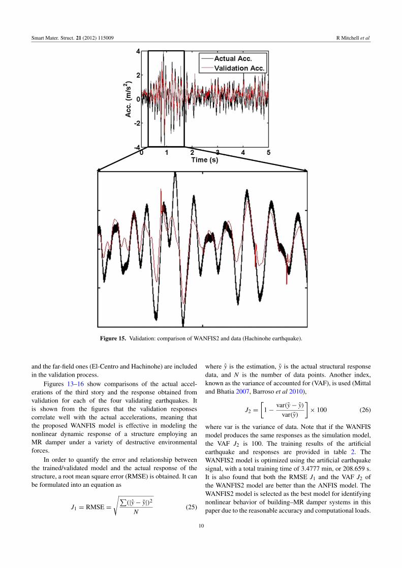
Figure 15. Validation: comparison of WANFIS2 and data (Hachinohe earthquake).
and the far-field ones (El-Centro and Hachinohe) are includedin the validation process.
Figures 13–16 show comparisons of the actual accel-erations of the third story and the response obtained fromvalidation for each of the four validating earthquakes. Itis shown from the figures that the validation responsescorrelate well with the actual accelerations, meaning thatthe proposed WANFIS model is effective in modeling thenonlinear dynamic response of a structure employing anMR damper under a variety of destructive environmentalforces.
In order to quantify the error and relationship betweenthe trained/validated model and the actual response of thestructure, a root mean square error (RMSE) is obtained. It canbe formulated into an equation as
J1 = RMSE =
√∑(|y− y|)2
N(25)
where y is the estimation, y is the actual structural responsedata, and N is the number of data points. Another index,known as the variance of accounted for (VAF), is used (Mittaland Bhatia 2007, Barroso et al 2010),
J2 =
[1−
var(y− y)
var(y)
]× 100 (26)
where var is the variance of data. Note that if the WANFISmodel produces the same responses as the simulation model,the VAF J2 is 100. The training results of the artificialearthquake and responses are provided in table 2. TheWANFIS2 model is optimized using the artificial earthquakesignal, with a total training time of 3.4777 min, or 208.659 s.It is also found that both the RMSE J1 and the VAF J2 ofthe WANFIS2 model are better than the ANFIS model. TheWANFIS2 model is selected as the best model for identifyingnonlinear behavior of building–MR damper systems in thispaper due to the reasonable accuracy and computational loads.
10

Smart Mater. Struct. 21 (2012) 115009 R Mitchell et al
Figure 16. Validation: comparison of WANFIS2 and data (Northridge earthquake).
Table 2. Training errors and times.
SystemTrainingtime (s) J1 J2
ANFIS 4815.120 3.6097 71.4769WANFIS1 1392.174 3.1488 69.5300WANFIS2 208.659 2.7464 76.8231
Thus, the WANFIS2 model is validated using four differentearthquake signals.
The validation errors are provided in table 3 for eachearthquake. Based on the training data, the WANFIS2 modelis preferred due to the more favorable computation times,quantified as roughly 90% less computation time, as wellas the better performance. For validation purposes, theWANFIS2 model resulted in adequate RMSE values for eachof the four validation earthquakes. The residual error plots forthe WANFIS2 model are also provided in figure 17.
Table 3. Validation of the trained model.
WANFIS2validation J1 J2
El-Centro 0.9255 83.3523Kobe 1.9608 84.0253Northridge 1.5431 77.7947Hachinohe 0.6126 81.0100
4. Conclusion
In this paper, a novel WANFIS is proposed for nonlinear SI ofseismically excited smart building structures that are equippedwith MR dampers. The WANFIS is an integrated model ofthe Takagi–Sugeno fuzzy model, wavelet transforms, andartificial neural networks. Using a WANFIS system combinesthe positive attributes of the three described methodologiesto create a system that is believed to yield more efficientresults for SI of smart structures and shorter training times.
11

Smart Mater. Struct. 21 (2012) 115009 R Mitchell et al
Figure 17. Residual errors for the WANFIS2 model.
To train the input–output mapping function of the WANFISmodel, an artificial earthquake signal and an MR damperforce signal are used as a disturbance input signal and acontrol input, respectively, while the acceleration responseis used as output data. This approach can be applied to anintegrated model of a primary building structure and nonlinearMR devices without decoupling the identification procedureof the highly nonlinear MR damper from that of the primarybuilding structure. It is demonstrated from the simulation thatthe proposed WANFIS model is effective in identifying thenonlinear behavior of the seismically excited building–MRdamper system while shortening the training time typical ofan ANFIS model.
References
Adeli H and Karim A 2000 Fuzzy-wavelet RBFNN for freewayincident detection J. Transp. Eng. 126 464–71
Adeli H and Kim H 2004 Wavelet-hybrid feedback-least meansquare algorithm for robust control of structures J. Struct. Eng.130 128–37
Adeli H and Samant A 2000 An adaptive conjugate gradient neuralnetwork-wavelet model for traffic incident detectionComput.-Aided Civil Infrastruct. Eng. 15 251–60
Alhanafy T E 2007 A systematic algorithm to construct neuro-fuzzyinference system 16th Int. Conf. on Software Engineering andData Engineering (Las Vegas, Nevada)
Barroso J, Borges J, Oliveira P, Pinheiro C C, Pires A C andSilva J M 2010 Nonlinear modeling of a real pilot scalecontinuous distillation process 20th European Symp. onComputer Aided Process Engineering vol 20,, pp 1733–8
Catalao J P S, Pousinho H M I and Mendes V 2011 Hybridwavelet-PSO-ANFIS approach for short-term wind powerforecasting in Portugal IEEE Trans. Sustainable Energy 2 50–9
Daubechies I 1992 Ten Lectures on Wavelets (Philadelphia, PA:Society for Industrial and Applied Mathematics)
Dyke S J, Spencer B F Jr, Sain M K and Carlson J D 1996Modeling and control of magnetorheological dampers forseismic response reduction Smart Mater. Struct. 5 565–75
Faravelli L and Yao T 1996 Use of adaptive networks in fuzzycontrol of civil structures Comput.-Aided Civil Infrastruct.Eng. 11 67–76
Filev D P 1991 Fuzzy modeling of complex systems Int. J. Approx.Reason. 5 281–90
Gopalakrishnan K and Khaitan S K 2010 Finite element basedadaptive neuro-fuzzy inference technique for parameteridentification of multi-layered transportation structuresTransport 25 58–65
Gu Z and Oyadiji S 2008 Application of MR Damper in structuralcontrol using ANFIS Method Comput. Struct. 86 427–36
Guo H, Dong Z and Ma X 2009 WANFIS model for monthly runoffforecasting Hydroinformatics in Hydrology, Hydrogeology andWater Resources, Proc. Symp. JS.4 at the Joint Convention ofthe International Association of Hydrological Sciences, IAHSand the International Association of Hydrogeologists (IAH,India)
Hung S L, Huang C S, Wen C M and Hsu Y C 2003 Nonparametricidentification of a building structure from experimental datausing wavelet neural network Comput.-Aided Civil Infrastruct.Eng. 18 356–68
Jalili-Kharaajoo M 2004 Nonlinear system identification usingANFIS based on emotional learning Lect. Notes Comput. Sci.3315 697–707
Jang J S R, Sun C T and Mizutani E 1997 Neuro-Fuzzy and SoftComputing (Upper Saddle River, NJ: Prentice Hall)
Johansen T A and Babuska R 2003 Multiobjective identification ofTakagi–Sugeno fuzzy models IEEE Trans. Fuzzy Syst.11 847–60
Karim A and Adeli H 2002a Comparison of fuzzy-wavelet radialbasis function neural network freeway incident detectionmodel with California algorithm J. Transp. Eng. 128 21–30
Karim A and Adeli H 2002b Incident detection algorithm usingwavelet energy representation of traffic patternsJ. Transp. Eng. 128 232–42
Kim Y, Hurlebaus S and Langari R 2011 Fuzzy identification ofbuilding-MR damper system Int. J. Intell. Fuzzy Syst. 22 1–21
Kim Y, Hurlebaus S, Sharifi R and Langari R 2009 Nonlinearidentification of MIMO smart structures ASME Dynamic Syst.Control Conf. (Hollywood, CA, Oct.)
Mallat S 1989 A theory for multiresolution signal decomposition:the wavelet representation IEEE Trans. Pattern Anal. Mach.Intell. 11 674–93
Mitchell R, Kim Y, El-Korchi T and Cha Y 2012 Wavelet-basedneuro-fuzzy controller for vibration mitigation of high-risebuildings J. Vib. Control at press
Mittal H and Bhatia P 2007 Optimization criteria for effortestimation using fuzzy technique CLEI Electron. J. 10 1–11
Samant A and Adeli H 2000 Feature extraction for traffic incidentdetection using wavelet transform and linear discriminantanalysis Comput. Aided Civil Infrastruct. Eng. 15 241–50
Samant A and Adeli H 2001 Enhancing neural network incidentdetection algorithms using wavelets Comput. Aided CivilInfrastruct. Eng. 16 239–45
Spencer B F Jr, Dyke S J, Sain M K and Carlson J D 1997Phenomenological model for magnetorheological dampersASCE J. Eng. Mech. 123 230–8
Takagi T and Sugeno M 1985 Fuzzy identification of systems andits applications to modeling and control IEEE Trans. Syst.Man, Cybern. 15 116–32
Thuillard M 2001 Wavelets in Soft Computing (Singapore: WorldScientific)
Wang H and Shi X M 2010 Hierarchical ANFIS identification ofmagneto-rheological dampers Appl. Mech. Mater. 29–32 343–8
Wu M and Adeli H 2001 Wavelet-neural network model forautomatic traffic incident detection Math. Comput. Appl.6 85–96
Yan J and Langari R 1998 Fuzzy Logic-Intelligence, Control, andInformation (Upper Saddle River, NJ: Prentice-Hall)
Zadeh L A 1965 Fuzzy sets Inform. Control 8 338–53
12